WO2009104449A1 - Interference prevention control device for operating machinery - Google Patents
Interference prevention control device for operating machinery Download PDFInfo
- Publication number
- WO2009104449A1 WO2009104449A1 PCT/JP2009/050933 JP2009050933W WO2009104449A1 WO 2009104449 A1 WO2009104449 A1 WO 2009104449A1 JP 2009050933 W JP2009050933 W JP 2009050933W WO 2009104449 A1 WO2009104449 A1 WO 2009104449A1
- Authority
- WO
- WIPO (PCT)
- Prior art keywords
- cab
- tool
- predicted
- boom
- arm
- Prior art date
Links
Images


Classifications
-
- E—FIXED CONSTRUCTIONS
- E02—HYDRAULIC ENGINEERING; FOUNDATIONS; SOIL SHIFTING
- E02F—DREDGING; SOIL-SHIFTING
- E02F3/00—Dredgers; Soil-shifting machines
- E02F3/04—Dredgers; Soil-shifting machines mechanically-driven
- E02F3/28—Dredgers; Soil-shifting machines mechanically-driven with digging tools mounted on a dipper- or bucket-arm, i.e. there is either one arm or a pair of arms, e.g. dippers, buckets
- E02F3/36—Component parts
- E02F3/42—Drives for dippers, buckets, dipper-arms or bucket-arms
- E02F3/43—Control of dipper or bucket position; Control of sequence of drive operations
-
- E—FIXED CONSTRUCTIONS
- E02—HYDRAULIC ENGINEERING; FOUNDATIONS; SOIL SHIFTING
- E02F—DREDGING; SOIL-SHIFTING
- E02F9/00—Component parts of dredgers or soil-shifting machines, not restricted to one of the kinds covered by groups E02F3/00 - E02F7/00
- E02F9/16—Cabins, platforms, or the like, for drivers
- E02F9/166—Cabins, platforms, or the like, for drivers movable, tiltable or pivoting, e.g. movable seats, dampening arrangements of cabins
-
- E—FIXED CONSTRUCTIONS
- E02—HYDRAULIC ENGINEERING; FOUNDATIONS; SOIL SHIFTING
- E02F—DREDGING; SOIL-SHIFTING
- E02F9/00—Component parts of dredgers or soil-shifting machines, not restricted to one of the kinds covered by groups E02F3/00 - E02F7/00
- E02F9/24—Safety devices, e.g. for preventing overload
Landscapes
- Engineering & Computer Science (AREA)
- Mining & Mineral Resources (AREA)
- Civil Engineering (AREA)
- General Engineering & Computer Science (AREA)
- Structural Engineering (AREA)
- Mechanical Engineering (AREA)
- Operation Control Of Excavators (AREA)
- Component Parts Of Construction Machinery (AREA)
Abstract
Disclosed is an interference prevention control device that is able to prevent interference between the tool and cab of an operating device, even when either the cab or the operating device moves while the other is moving, and can thereby improve operating efficiency. In operating machinery equipped with a movable cab, a cab position sensor (43) that detects the cab position, and a boom angle sensor (41) and an arm angle sensor (42) that detect the tool position at the tip of the operating device, are connected to a controller (77). Proportional solenoid valves (71-74), which regulate the operation of a boom cylinder (23) and an arm cylinder (26) that operate the operating device, are arranged in the pilot pathway of a pilot-operated control valve (47), and the solenoids are connected to the controller (77). The controller (77) finds the motion vector from the cab position detected by the cab position sensor (43) and the differentially calculated cab movement velocity, predicts the cab position after a set period of time, and controls the boom cylinder (23) and the arm cylinder (26) by means of the proportional solenoid valves (71-74) so that there is no interference between the predicted position and the tool position.
Description
本発明は、機体に搭載されたキャブおよび作業装置が機体に対しそれぞれ可動的に設けられた作業機械における干渉防止制御装置に関する。
The present invention relates to an interference prevention control device in a work machine in which a cab and a work device mounted on the airframe are movably provided with respect to the airframe.
機体に搭載されたキャブおよび作業装置が機体に対しそれぞれ可動的に設けられた作業機械において、従来のキャブと作業装置との干渉を防止するキャブ干渉防止制御は、キャブの移動した量を検出し、その移動量の実際の検出結果に基づいて、キャブと作業装置とが干渉しないように干渉防止領域を補正している(例えば、特許文献1参照)。
特許第3310783号公報(第4-5頁、図3-5)
In a work machine in which the cab and work equipment mounted on the airframe are movably provided to the airframe, the conventional cab interference prevention control that prevents interference between the cab and the work equipment detects the amount of cab movement. Based on the actual detection result of the movement amount, the interference prevention area is corrected so that the cab and the work device do not interfere with each other (see, for example, Patent Document 1).
Japanese Patent No. 3310783 (page 4-5, Fig. 3-5)
上記干渉防止装置は、実際にキャブが移動した量を把握した上で干渉防止領域を補正するので、キャブが移動している最中は、作業装置の干渉防止制御は困難であり、また、作業中にキャブが移動することで作業装置と干渉するおそれもある。
The interference prevention device corrects the interference prevention area after grasping the amount of actual cab movement. Therefore, while the cab is moving, it is difficult to control the interference of the work device. If the cab moves inside, there is a risk of interference with the work equipment.
本発明は、このような点に鑑みなされたもので、キャブおよび作業装置の一方が動いている最中に他方を動かしても作業装置のツールとキャブとの干渉を防止でき、作業能率を向上できる作業機械における干渉防止制御装置を提供することを目的とする。
The present invention has been made in view of such a point, and even if one of the cab and the working device is moving, the other can be moved to prevent interference between the tool of the working device and the cab, thereby improving work efficiency. An object of the present invention is to provide an interference prevention control device for a working machine.
請求項1に記載された発明は、機体に搭載されたキャブおよび作業装置が、機体に対しそれぞれ可動的に設けられた作業機械において、キャブの位置を検出するキャブ位置センサと、作業装置に取付けられたツールの位置を検出するツール位置センサと、作業装置を作動するアクチュエータの動作を規制する規制手段と、キャブ位置センサにより検出されたキャブの位置およびこの位置を微分して演算したキャブの移動速度からキャブの移動ベクトルを求め、このキャブの移動ベクトルから一定時間後のキャブの位置を予測するとともに、その予測されたキャブの位置とツールの位置とが干渉しないように規制手段により作業装置のアクチュエータ動作を制御するコントローラとを具備した作業機械における干渉防止制御装置である。
According to a first aspect of the present invention, there is provided a cab position sensor for detecting a position of a cab in a work machine in which a cab and a work device mounted on the airframe are movably provided with respect to the airframe, and attached to the work device. A tool position sensor for detecting the position of the detected tool, a restricting means for restricting the operation of an actuator for operating the work device, a cab position detected by the cab position sensor, and a cab movement calculated by differentiating the position. The movement vector of the cab is obtained from the speed, the position of the cab after a certain time is predicted from the movement vector of the cab, and the control device of the work device is controlled by the regulating means so that the predicted position of the cab and the position of the tool do not interfere with each other. An interference prevention control apparatus in a work machine including a controller that controls actuator operation.
請求項2に記載された発明は、機体に搭載されたキャブおよび作業装置が、機体に対しそれぞれ可動的に設けられた作業機械において、キャブの位置を検出するキャブ位置センサと、作業装置に取付けられたツールの位置を検出するツール位置センサと、キャブを作動するアクチュエータの動作を規制する規制手段と、ツール位置センサにより検出されたツールの位置およびこの位置を微分して演算したツールの移動速度からツールの移動ベクトルを求め、このツールの移動ベクトルから一定時間後のツールの位置を予測するとともに、その予測されたツールの位置とキャブの位置とが干渉しないように規制手段によりキャブのアクチュエータ動作を制御するコントローラとを具備した作業機械における干渉防止制御装置である。
According to a second aspect of the present invention, there is provided a cab position sensor for detecting a position of a cab and a work device attached to the work device in a work machine in which the cab and the work device mounted on the airframe are movably provided with respect to the airframe. Tool position sensor that detects the position of the tool that has been detected, regulation means that regulates the operation of the actuator that operates the cab, the position of the tool detected by the tool position sensor, and the moving speed of the tool calculated by differentiating this position The tool movement vector is obtained from the tool, the tool position after a certain time is predicted from the tool movement vector, and the cab actuator operation is controlled by the regulating means so that the predicted tool position and the cab position do not interfere with each other. It is the interference prevention control apparatus in the working machine provided with the controller which controls.
請求項3に記載された発明は、請求項1または2記載の作業機械における干渉防止制御装置において、規制手段によって動作規制されるアクチュエータを、パイロット操作式コントロール弁により動作制御される油圧アクチュエータとし、規制手段を、パイロット操作式コントロール弁のパイロット通路中に設けられた電磁比例弁としたものである。
According to a third aspect of the present invention, in the interference prevention control device for a work machine according to the first or second aspect, the actuator whose operation is regulated by the regulating means is a hydraulic actuator whose operation is controlled by a pilot operated control valve, The restricting means is an electromagnetic proportional valve provided in the pilot passage of the pilot operated control valve.
請求項4に記載された発明は、請求項3記載の作業機械における干渉防止制御装置のコントローラが、一定時間後の予測された位置関係から、所定量の動作でツールとキャブとが干渉しないと判断した場合は、電磁比例弁に最大指令信号を出力するとともに、干渉すると判断した場合は、位置関係に応じた指令信号を出力するものである。
According to a fourth aspect of the present invention, when the controller of the interference prevention control device in the work machine according to the third aspect of the present invention is such that the tool and the cab do not interfere with each other by a predetermined amount of operation based on the predicted positional relationship after a predetermined time. When it is determined, a maximum command signal is output to the electromagnetic proportional valve, and when it is determined that interference occurs, a command signal corresponding to the positional relationship is output.
請求項1に記載された発明によれば、コントローラが、キャブ位置センサにより検出されたキャブの位置およびこの位置を微分して演算したキャブの移動速度からキャブの移動ベクトルを求め、このキャブの移動ベクトルから一定時間後のキャブの位置を予測するとともに、その予測されたキャブの位置とツールの位置とが干渉しないように規制手段により作業装置のアクチュエータ動作を制御するので、キャブが移動している最中に作業装置を動かしても、作業装置のツールとキャブとの干渉を防止でき、作業能率を向上できる。
According to the first aspect of the present invention, the controller obtains the cab movement vector from the cab position detected by the cab position sensor and the cab movement speed calculated by differentiating the position, and the cab movement is calculated. The position of the cab after a certain time is predicted from the vector, and the actuator operation of the work device is controlled by the restricting means so that the predicted position of the cab and the position of the tool do not interfere with each other. Even if the working device is moved during the operation, interference between the tool of the working device and the cab can be prevented, and the working efficiency can be improved.
請求項2に記載された発明によれば、コントローラが、ツール位置センサにより検出されたツールの位置およびこの位置を微分して演算したツールの移動速度からツールの移動ベクトルを求め、このツールの移動ベクトルから一定時間後のツールの位置を予測するとともに、その予測されたツールの位置とキャブの位置とが干渉しないように規制手段によりキャブのアクチュエータ動作を制御するので、作業装置が動いている最中すなわち作業中にキャブを移動させても、作業装置のツールとキャブとの干渉を防止でき、作業能率を向上できる。
According to the invention described in claim 2, the controller obtains the tool movement vector from the position of the tool detected by the tool position sensor and the moving speed of the tool calculated by differentiating the position, and the movement of the tool The position of the tool after a certain time is predicted from the vector, and the cab actuator operation is controlled by the regulating means so that the predicted tool position and the cab position do not interfere with each other. Even if the cab is moved during, that is, during work, interference between the tool of the working device and the cab can be prevented, and work efficiency can be improved.
請求項3に記載された発明によれば、規制手段は、油圧アクチュエータを動作制御するパイロット操作式コントロール弁のパイロット通路中に設けられた電磁比例弁であるので、油圧アクチュエータの動作を高精度に制御して、作業装置のツールとキャブとの干渉を確実に防止できる。。
According to the invention described in claim 3, since the regulating means is an electromagnetic proportional valve provided in the pilot passage of the pilot operated control valve for controlling the operation of the hydraulic actuator, the operation of the hydraulic actuator can be performed with high accuracy. Control can reliably prevent interference between the tool of the working device and the cab. .
請求項4に記載された発明によれば、コントローラが、一定時間後の予測された位置関係から、所定量の動作でツールとキャブとが干渉しないと判断した場合は、電磁比例弁に最大指令信号を出力して、作業能率の高い高速動作が得られるとともに、干渉すると判断した場合は、位置関係に応じた指令信号を電磁比例弁に出力するので、ツールとキャブとが近づくにしたがって減速して、ショックレスの円滑な停止動作が得られる。
According to the invention described in claim 4, when the controller determines that the tool and the cab do not interfere with each other by a predetermined amount of operation based on the predicted positional relationship after a predetermined time, the maximum command is sent to the electromagnetic proportional valve. When a signal is output, high-speed operation with high work efficiency is obtained, and when it is determined that interference occurs, a command signal corresponding to the positional relationship is output to the electromagnetic proportional valve, so the speed decreases as the tool and cab approach each other. Thus, a smooth stop operation without shock can be obtained.
10 作業機械
11 機体
12 作業装置としてのフロント作業装置
13 キャブ
23 アクチュエータとしてのブームシリンダ
26 アクチュエータとしてのアームシリンダ
28 ツール
32 アクチュエータとしてのキャブ昇降シリンダ
41 ツール位置センサとしてのブーム角センサ
42 ツール位置センサとしてのアーム角センサ
43 キャブ位置センサ
47 パイロット操作式コントロール弁
61~66 パイロット通路としての2次圧通路
71~76 規制手段としての電磁比例弁
77 コントローラ
81~85 移動ベクトル 10Work machine 11 Machine body 12 Front work device as work device 13 Cab 23 Boom cylinder as actuator 26 Arm cylinder as actuator 28 Tool 32 Cab lift cylinder as actuator 41 Boom angle sensor as tool position sensor 42 Tool position sensor Arm angle sensor 43 Cab position sensor 47 Pilot operated control valve 61 to 66 Secondary pressure passage as pilot passage 71 to 76 Proportional solenoid valve as regulating means 77 Controller 81 to 85 Movement vector
11 機体
12 作業装置としてのフロント作業装置
13 キャブ
23 アクチュエータとしてのブームシリンダ
26 アクチュエータとしてのアームシリンダ
28 ツール
32 アクチュエータとしてのキャブ昇降シリンダ
41 ツール位置センサとしてのブーム角センサ
42 ツール位置センサとしてのアーム角センサ
43 キャブ位置センサ
47 パイロット操作式コントロール弁
61~66 パイロット通路としての2次圧通路
71~76 規制手段としての電磁比例弁
77 コントローラ
81~85 移動ベクトル 10
以下、本発明を、図面に示された一実施の形態を参照しながら詳細に説明する。
Hereinafter, the present invention will be described in detail with reference to an embodiment shown in the drawings.
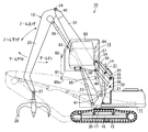
図2は、作業機械10を示し、機体11に作業装置としてのフロント作業装置12が設置され、このフロント作業装置12の側方にて機体11上にキャブ13が、機体11に対し昇降可能に設けられ、機体11とキャブ13との間には、このキャブ13を昇降するキャブ移動装置14が設けられている。機体11は、履帯15を装着された下部走行体16に、上部旋回体17が旋回可能に設けられている。
FIG. 2 shows a work machine 10, and a front work device 12 as a work device is installed on the machine body 11, and a cab 13 on the machine body 11 can be moved up and down with respect to the machine body 11 at the side of the front work device 12. A cab moving device 14 for raising and lowering the cab 13 is provided between the airframe 11 and the cab 13. In the airframe 11, an upper revolving body 17 is turnably provided on a lower traveling body 16 to which a crawler belt 15 is attached.
キャブ13とともに機体11に設置されたフロント作業装置12は、機体11の旋回フレーム20に対し、ブームフートピン21により、ブーム22の基端が回動自在に軸支され、旋回フレーム20とブーム22との間に、ブーム22を上下方向に回動するアクチュエータとしてのブームシリンダ23が設けられ、ブーム22の先端に対し、ブーム先端ピン24により、アーム25の基端が回動自在に軸支され、ブーム22とアーム25との間に、アームを回動するアクチュエータとしてのアームシリンダ26が設けられ、アーム25の先端に、アーム先端ピン27によりツール28が軸支されている。
The front work device 12 installed in the body 11 together with the cab 13 is pivotally supported by a boom foot pin 21 so that the base end of the boom 22 can be pivoted with respect to the turning frame 20 of the body 11. The boom cylinder 23 is provided as an actuator for rotating the boom 22 in the vertical direction, and the base end of the arm 25 is pivotally supported by the boom distal end pin 24 with respect to the distal end of the boom 22. An arm cylinder 26 serving as an actuator for rotating the arm is provided between the boom 22 and the arm 25, and a tool 28 is pivotally supported at the tip of the arm 25 by an arm tip pin 27.
図示されたツール28は、解体作業などに用いられるグラップルであり、このグラップルは、ワークを把持するためにツール用アクチュエータ(図示せず)により開閉駆動されるので、その径が変化する。ツールとしては、クラムシェルバケット、マグネットまたはフォークなどを用いても良い。
The illustrated tool 28 is a grapple used for dismantling work and the like, and this grapple is driven to open and close by a tool actuator (not shown) in order to grip the workpiece, so that its diameter changes. As a tool, a clamshell bucket, a magnet or a fork may be used.
キャブ移動装置14は、キャブ13を所定の姿勢に保つリンク機構31と、キャブ13を昇降駆動するアクチュエータとしてのキャブ昇降シリンダ32とを備えている。
The cab moving device 14 includes a link mechanism 31 that keeps the cab 13 in a predetermined posture, and a cab elevating cylinder 32 as an actuator that drives the cab 13 up and down.
リンク機構31は、機体11の上部旋回体17上に立設された支持塔体33と、キャブ13の下部に一体に設けられたL形のリンク接続部34と、支持塔体33の上部とリンク接続部34の後背部との間に常に平行に保たれるようにピン35,36,37,38により回動自在に連結されキャブ昇降シリンダ32により上下方向に回動される上リンク39および下リンク40とを具備している。
The link mechanism 31 includes a support tower 33 erected on the upper swing body 17 of the airframe 11, an L-shaped link connection 34 integrally provided at the lower part of the cab 13, and an upper part of the support tower 33. An upper link 39 that is pivotally connected by pins 35, 36, 37, and 38 and is vertically rotated by a cab elevating cylinder 32 so as to be always kept parallel to the rear portion of the link connecting portion 34, and And a lower link 40.
キャブ昇降シリンダ32の基端は、支持塔体33の下部にピンにより回動自在に軸支され、キャブ昇降シリンダ32のピストンロッド先端は、上リンク39にピンにより回動自在に連結されている。
The base end of the cab elevating cylinder 32 is pivotally supported by a pin at the bottom of the support tower 33, and the piston rod tip of the cab elevating cylinder 32 is rotatably connected to the upper link 39 by a pin. .
このように、キャブ13は、キャブ移動装置14により昇降可能に設けられ、また、フロント作業装置12は、機体11に対しブームフートピン21を中心にブームシリンダ23により回動されるブーム22と、このブーム22に対しブーム先端ピン24を中心にアームシリンダ26により回動されるアーム25と、このアーム25に対しアーム先端ピン27を中心に回動可能なツール28とを備えている。
As described above, the cab 13 is provided so as to be movable up and down by the cab moving device 14, and the front work device 12 includes a boom 22 that is rotated by the boom cylinder 23 around the boom foot pin 21 with respect to the body 11, and An arm 25 rotated by an arm cylinder 26 about the boom tip pin 24 with respect to the boom 22 and a tool 28 rotatable about the arm tip pin 27 with respect to the arm 25 are provided.
このフロント作業装置12の先端部に取付けられたツール28の位置を検出するツール位置センサとして、ブームフートピン21の一端部には旋回フレーム20に対するブーム22の角度位置を検出するブーム角センサ41が取付けられ、ブーム先端ピン24の一端部にはブーム22に対するアーム25の角度位置を検出するアーム角センサ42が取付けられている。また、ピン35の一端部には、支持塔体33に対する上リンク39の角度位置を検出することでキャブ13の位置を検出するキャブ位置センサ43が設けられている。これらのブーム角センサ41、アーム角センサ42およびキャブ位置センサ43は、回転型ポテンショメータなどを用いる。
As a tool position sensor for detecting the position of the tool 28 attached to the front end portion of the front working device 12, a boom angle sensor 41 for detecting the angular position of the boom 22 with respect to the turning frame 20 is provided at one end of the boom foot pin 21. An arm angle sensor 42 that detects the angular position of the arm 25 with respect to the boom 22 is attached to one end of the boom tip pin 24. A cab position sensor 43 that detects the position of the cab 13 by detecting the angular position of the upper link 39 with respect to the support tower 33 is provided at one end of the pin 35. These boom angle sensor 41, arm angle sensor 42, and cab position sensor 43 use a rotary potentiometer or the like.
図1には、各シリンダを制御する制御回路が示され、キャブ13内には、座席上のオペレータにより手動操作される操作器としての操作弁44,45,46が設置され、一方、機体11側には、下部走行体16に装着された走行モータ(図示せず)、下部走行体16に対し上部旋回体17を旋回駆動する旋回モータ(図示せず)、ブームシリンダ23、アームシリンダ26、キャブ昇降シリンダ32などの油圧アクチュエータを制御するパイロット操作式コントロール弁47が設置されている。
FIG. 1 shows a control circuit for controlling each cylinder. In the cab 13, operating valves 44, 45, and 46 are installed as operating devices that are manually operated by an operator on the seat. On the side, a traveling motor (not shown) attached to the lower traveling body 16, a turning motor (not shown) for driving the upper turning body 17 to rotate relative to the lower traveling body 16, a boom cylinder 23, an arm cylinder 26, A pilot operated control valve 47 for controlling a hydraulic actuator such as the cab elevating cylinder 32 is provided.
このパイロット操作式コントロール弁47は、ブームシリンダ23、アームシリンダ26およびキャブ昇降シリンダ32のそれぞれを制御するスプール48,49,50を少なくとも含んでいる。
This pilot operated control valve 47 includes at least spools 48, 49 and 50 for controlling the boom cylinder 23, the arm cylinder 26 and the cab elevating cylinder 32, respectively.
これらのスプール48,49,50は、車載エンジンなどの原動機51により駆動されるメインポンプ52から、タンク53内の作動油がメイン通路54を経てそれぞれ供給されると、これらのスプール48,49,50からブームシリンダ23、アームシリンダ26およびキャブ昇降シリンダ32のそれぞれに供給される作動油をストローク位置により方向制御および流量制御し、戻り油をタンク53に戻す働きがある。
When the hydraulic oil in the tank 53 is supplied from the main pump 52 driven by the prime mover 51 such as an in-vehicle engine through the main passage 54, these spools 48, 49, 50 are respectively supplied to the spools 48, 49, 50. The hydraulic oil supplied from 50 to each of the boom cylinder 23, the arm cylinder 26, and the cab elevating cylinder 32 has a function of controlling the direction and flow rate according to the stroke position and returning the return oil to the tank 53.
原動機51によりメインポンプ52とともに駆動されるパイロットポンプ55は、リリーフ弁56で設定されたパイロット1次圧のパイロット圧油を、チェック弁57を有する1次圧通路58を経て各操作弁44,45,46に供給する。各操作弁44,45,46は、レバー操作量に応じたパイロット2次圧をパイロット通路としての2次圧通路61,62,63,64,65,66を経て各スプール48,49,50のパイロット操作部に供給する。
The pilot pump 55 driven by the prime mover 51 together with the main pump 52 passes the pilot pressure oil of the pilot primary pressure set by the relief valve 56 through the primary pressure passage 58 having the check valve 57 to the respective operation valves 44, 45. , 46. Each of the operation valves 44, 45, and 46 has a pilot secondary pressure corresponding to the amount of lever operation via a secondary pressure passage 61, 62, 63, 64, 65, 66 as a pilot passage. Supply to the pilot control unit.
ブーム用の2次圧通路61,62中には、規制手段としての電磁比例弁71,72が介在され、アーム用の2次圧通路63,64中には、規制手段としての電磁比例弁73,74が介在され、キャブ用の2次圧通路65,66中には、規制手段としての電磁比例弁75,76が介在されている。
In the secondary pressure passages 61 and 62 for the boom, electromagnetic proportional valves 71 and 72 are provided as restricting means, and in the secondary pressure passages 63 and 64 for the arm, an electromagnetic proportional valve 73 as the restricting means is provided. 74, and electromagnetic proportional valves 75 and 76 as restricting means are interposed in the secondary pressure passages 65 and 66 for the cab.
これらの電磁比例弁71~76は、ソレノイドを備え、その各ソレノイドは、コントローラ77の出力部に接続されている。このコントローラ77の入力部には、前記のブーム角センサ41、アーム角センサ42およびキャブ位置センサ43が接続され、さらに、干渉防止制御を開始させるスイッチ78が接続されている。
These electromagnetic proportional valves 71 to 76 are provided with solenoids, and each solenoid is connected to an output section of the controller 77. The boom angle sensor 41, the arm angle sensor 42, and the cab position sensor 43 are connected to an input portion of the controller 77, and a switch 78 for starting interference prevention control is further connected.
コントローラ77は、キャブ位置センサ43により検出されたキャブ13の位置(以下、キャブ13の位置は、キャブ13の周囲に設定されたキャブ干渉域80の位置を意味する)およびこのキャブ13の位置を微分して演算したキャブ13の移動速度から、図2に示されるようにキャブ干渉域80が一定時間後のキャブ予測位置80aへと移動する際の移動ベクトル81,82,83,84,85を求め、このキャブ干渉域80の移動ベクトル81,82,83,84,85から一定時間後のキャブ位置を予測するとともに、その予測されたキャブ位置とツール位置とが干渉しないように電磁比例弁71,72,73,74によりフロント作業装置12のアクチュエータ動作を制御するものである。
The controller 77 determines the position of the cab 13 detected by the cab position sensor 43 (hereinafter, the position of the cab 13 means the position of the cab interference zone 80 set around the cab 13) and the position of the cab 13. As shown in FIG. 2, the movement vector 81, 82, 83, 84, 85 when the cab interference area 80 moves to the predicted cab position 80a after a certain time is calculated from the moving speed of the cab 13 calculated by differentiation. The cab position after a predetermined time is predicted from the movement vectors 81, 82, 83, 84, 85 of the cab interference area 80, and the proportional valve 71 is used so that the predicted cab position does not interfere with the tool position. , 72, 73, 74 control the actuator operation of the front working device 12.
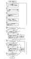
次に、図3に示されたフローチャートを参照しながら、コントローラ77による干渉防止制御Aを説明する。なお、このフローチャートにおける丸数字は、制御手順を示すステップ番号である。
Next, the interference prevention control A by the controller 77 will be described with reference to the flowchart shown in FIG. The circled numbers in this flowchart are step numbers indicating control procedures.
(ステップ1)
ブーム角センサ41およびアーム角センサ42によりブーム角およびアーム角を検出して、これらに既知のブーム長およびアーム長を掛けることで、アーム先端の座標すなわちツール28の位置を求める。 (Step 1)
The boom angle and arm angle are detected by theboom angle sensor 41 and the arm angle sensor 42, and the known boom length and arm length are multiplied by these to obtain the coordinates of the arm tip, that is, the position of the tool 28.
ブーム角センサ41およびアーム角センサ42によりブーム角およびアーム角を検出して、これらに既知のブーム長およびアーム長を掛けることで、アーム先端の座標すなわちツール28の位置を求める。 (Step 1)
The boom angle and arm angle are detected by the
(ステップ2)
キャブ位置センサ43によりリンク機構31の角度を検出することで、キャブ位置(すなわち、キャブ干渉域80の位置)を求める。このとき、キャブ13は、リンク機構31により水平に昇降するので、キャブ13の1点(例えばピン37など)の座標を決めて、その1点の座標変化を追跡することで、キャブ干渉域80の各部位置の変化を把握することができる。 (Step 2)
The cab position (that is, the position of the cab interference area 80) is obtained by detecting the angle of thelink mechanism 31 by the cab position sensor 43. At this time, since the cab 13 is moved up and down horizontally by the link mechanism 31, the cab interference area 80 is determined by determining the coordinates of one point (for example, the pin 37) of the cab 13 and tracking the coordinate change of the one point. It is possible to grasp the change in the position of each part.
キャブ位置センサ43によりリンク機構31の角度を検出することで、キャブ位置(すなわち、キャブ干渉域80の位置)を求める。このとき、キャブ13は、リンク機構31により水平に昇降するので、キャブ13の1点(例えばピン37など)の座標を決めて、その1点の座標変化を追跡することで、キャブ干渉域80の各部位置の変化を把握することができる。 (Step 2)
The cab position (that is, the position of the cab interference area 80) is obtained by detecting the angle of the
(ステップ3)
キャブ位置(時間関数)を時間で微分することにより、キャブ13の移動速度を演算する。 (Step 3)
The moving speed of thecab 13 is calculated by differentiating the cab position (time function) with respect to time.
キャブ位置(時間関数)を時間で微分することにより、キャブ13の移動速度を演算する。 (Step 3)
The moving speed of the
(ステップ4)
キャブ位置とキャブ移動速度とから、キャブ干渉域80の移動ベクトル81,82,83,84,85を求める。 (Step 4)
From the cab position and the cab moving speed, movement vectors 81, 82, 83, 84, 85 of the cab interference area 80 are obtained.
キャブ位置とキャブ移動速度とから、キャブ干渉域80の移動ベクトル81,82,83,84,85を求める。 (Step 4)
From the cab position and the cab moving speed,
(ステップ5)
移動ベクトル81,82,83,84,85から一定時間後のキャブ予測位置80aを予測する。 (Step 5)
A predictedcab position 80a after a predetermined time is predicted from the movement vectors 81, 82, 83, 84, 85.
移動ベクトル81,82,83,84,85から一定時間後のキャブ予測位置80aを予測する。 (Step 5)
A predicted
(ステップ6)
ブーム上げ操作指令があるか否かを判断する。ブーム上げ操作指令がない場合は、ステップ10に進む。 (Step 6)
It is determined whether there is a boom raising operation command. If there is no boom raising operation command, the process proceeds to step 10.
ブーム上げ操作指令があるか否かを判断する。ブーム上げ操作指令がない場合は、ステップ10に進む。 (Step 6)
It is determined whether there is a boom raising operation command. If there is no boom raising operation command, the process proceeds to step 10.
(ステップ7)
ブーム上げ操作指令がある場合は、所定量すなわち所定角度のブーム上げ動作でツール28が移動ベクトル81,82,83,84,85のいずれかと干渉するか否かを判断する。 (Step 7)
When there is a boom raising operation command, it is determined whether or not thetool 28 interferes with any of the movement vectors 81, 82, 83, 84, 85 in a boom raising operation of a predetermined amount, that is, a predetermined angle.
ブーム上げ操作指令がある場合は、所定量すなわち所定角度のブーム上げ動作でツール28が移動ベクトル81,82,83,84,85のいずれかと干渉するか否かを判断する。 (Step 7)
When there is a boom raising operation command, it is determined whether or not the
(ステップ8)
所定角度のブーム上げ動作でツール28が移動ベクトル81,82,83,84,85のいずれとも干渉しないと判断した場合は、ブーム上げ用の電磁比例弁72に最大指令信号を出力して、この電磁比例弁72を全開状態に制御する。これにより、操作弁44からのブーム上げ操作用のパイロット2次圧は規制されないので、操作弁44の操作量に応じたブーム上げ速度が得られる。 (Step 8)
When it is determined that thetool 28 does not interfere with any of the movement vectors 81, 82, 83, 84, 85 during the boom raising operation at a predetermined angle, a maximum command signal is output to the electromagnetic proportional valve 72 for raising the boom, The electromagnetic proportional valve 72 is controlled to be fully opened. Thereby, since the pilot secondary pressure for the boom raising operation from the operation valve 44 is not restricted, the boom raising speed corresponding to the operation amount of the operation valve 44 can be obtained.
所定角度のブーム上げ動作でツール28が移動ベクトル81,82,83,84,85のいずれとも干渉しないと判断した場合は、ブーム上げ用の電磁比例弁72に最大指令信号を出力して、この電磁比例弁72を全開状態に制御する。これにより、操作弁44からのブーム上げ操作用のパイロット2次圧は規制されないので、操作弁44の操作量に応じたブーム上げ速度が得られる。 (Step 8)
When it is determined that the
(ステップ9)
所定角度のブーム上げ動作でツール28が移動ベクトル81,82,83,84,85のいずれかと干渉すると判断した場合は、一定時間後のキャブ予測位置(キャブ干渉域80のキャブ予測位置80a)との間で時々刻々と変化するツール28の残り角度に応じた指令信号をブーム上げ用の電磁比例弁72に出力する。これにより、操作弁44からの操作量に応じたブーム上げ操作用のパイロット2次圧が発生していても、図4に示されるように残り角度が小さくなるほど、コントローラ77から電磁比例弁72に出力される電磁比例弁指令信号を漸次減少させ、操作弁44の操作量と関係なく、電磁比例弁72によりブーム上げ操作用のパイロット2次圧を、零に至るまで漸次絞っていく。 (Step 9)
When it is determined that thetool 28 interferes with any of the movement vectors 81, 82, 83, 84, 85 by the boom raising operation at a predetermined angle, the predicted cab position (the predicted cab position 80a of the cab interference area 80) after a certain time A command signal corresponding to the remaining angle of the tool 28 that changes from moment to moment is output to the electromagnetic valve 72 for raising the boom. Thereby, even if the pilot secondary pressure for boom raising operation according to the operation amount from the operation valve 44 is generated, as the remaining angle becomes smaller as shown in FIG. The electromagnetic proportional valve command signal to be output is gradually reduced, and the pilot secondary pressure for boom raising operation is gradually reduced to zero by the electromagnetic proportional valve 72 regardless of the operation amount of the operation valve 44.
所定角度のブーム上げ動作でツール28が移動ベクトル81,82,83,84,85のいずれかと干渉すると判断した場合は、一定時間後のキャブ予測位置(キャブ干渉域80のキャブ予測位置80a)との間で時々刻々と変化するツール28の残り角度に応じた指令信号をブーム上げ用の電磁比例弁72に出力する。これにより、操作弁44からの操作量に応じたブーム上げ操作用のパイロット2次圧が発生していても、図4に示されるように残り角度が小さくなるほど、コントローラ77から電磁比例弁72に出力される電磁比例弁指令信号を漸次減少させ、操作弁44の操作量と関係なく、電磁比例弁72によりブーム上げ操作用のパイロット2次圧を、零に至るまで漸次絞っていく。 (Step 9)
When it is determined that the
(ステップ10)
次に、ブーム下げ操作指令があるか否かを判断する。ブーム下げ操作指令がない場合は、ステップ14に進む。 (Step 10)
Next, it is determined whether or not there is a boom lowering operation command. If there is no boom lowering operation command, the process proceeds to step 14.
次に、ブーム下げ操作指令があるか否かを判断する。ブーム下げ操作指令がない場合は、ステップ14に進む。 (Step 10)
Next, it is determined whether or not there is a boom lowering operation command. If there is no boom lowering operation command, the process proceeds to step 14.
(ステップ11)
ブーム下げ操作指令がある場合は、所定角度のブーム下げ動作でツール28が移動ベクトル81,82,83,84,85のいずれかと干渉するか否かを判断する。 (Step 11)
If there is a boom lowering operation command, it is determined whether or not thetool 28 interferes with any of the movement vectors 81, 82, 83, 84, 85 in a boom lowering operation at a predetermined angle.
ブーム下げ操作指令がある場合は、所定角度のブーム下げ動作でツール28が移動ベクトル81,82,83,84,85のいずれかと干渉するか否かを判断する。 (Step 11)
If there is a boom lowering operation command, it is determined whether or not the
(ステップ12)
所定角度のブーム下げ動作でツール28が移動ベクトル81,82,83,84,85のいずれとも干渉しないと判断した場合は、ブーム下げ用の電磁比例弁71に最大指令信号を出力して、この電磁比例弁71を全開状態に制御する。これにより、操作弁44からのブーム下げ操作用のパイロット2次圧は規制されないので、操作弁44の操作量に応じたブーム下げ速度が得られる。 (Step 12)
When it is determined that thetool 28 does not interfere with any of the movement vectors 81, 82, 83, 84, and 85 during the boom lowering operation at a predetermined angle, a maximum command signal is output to the electromagnetic proportional valve 71 for lowering the boom. The electromagnetic proportional valve 71 is controlled to be fully opened. Thereby, since the pilot secondary pressure for the boom lowering operation from the operation valve 44 is not regulated, the boom lowering speed corresponding to the operation amount of the operation valve 44 is obtained.
所定角度のブーム下げ動作でツール28が移動ベクトル81,82,83,84,85のいずれとも干渉しないと判断した場合は、ブーム下げ用の電磁比例弁71に最大指令信号を出力して、この電磁比例弁71を全開状態に制御する。これにより、操作弁44からのブーム下げ操作用のパイロット2次圧は規制されないので、操作弁44の操作量に応じたブーム下げ速度が得られる。 (Step 12)
When it is determined that the
(ステップ13)
所定角度のブーム下げ動作でツール28が移動ベクトル81,82,83,84,85のいずれかと干渉すると判断した場合は、一定時間後のキャブ予測位置(キャブ干渉域80のキャブ予測位置80a)との間で時々刻々と変化するツール28の残り角度に応じた指令信号をブーム下げ用の電磁比例弁71に出力する。これにより、操作弁44からの操作量に応じたブーム下げ操作用のパイロット2次圧が発生していても、図4に示されるように残り角度が小さくなるほど、コントローラ77から電磁比例弁71に出力される電磁比例弁指令信号を漸次減少させ、操作弁44の操作量と関係なく、電磁比例弁71によりブーム下げ操作用のパイロット2次圧を、零に至るまで漸次絞っていく。 (Step 13)
When it is determined that thetool 28 interferes with any of the movement vectors 81, 82, 83, 84, 85 by the boom lowering operation at a predetermined angle, the predicted cab position (the predicted cab position 80a of the cab interference area 80) after a certain time A command signal corresponding to the remaining angle of the tool 28 that changes from moment to moment is output to the electromagnetic proportional valve 71 for lowering the boom. As a result, even if the pilot secondary pressure for boom lowering operation corresponding to the operation amount from the operation valve 44 is generated, the controller 77 changes the proportional proportional valve 71 from the controller 77 as the remaining angle becomes smaller as shown in FIG. The output electromagnetic proportional valve command signal is gradually decreased, and the pilot secondary pressure for boom lowering operation is gradually reduced to zero by the electromagnetic proportional valve 71 regardless of the operation amount of the operation valve 44.
所定角度のブーム下げ動作でツール28が移動ベクトル81,82,83,84,85のいずれかと干渉すると判断した場合は、一定時間後のキャブ予測位置(キャブ干渉域80のキャブ予測位置80a)との間で時々刻々と変化するツール28の残り角度に応じた指令信号をブーム下げ用の電磁比例弁71に出力する。これにより、操作弁44からの操作量に応じたブーム下げ操作用のパイロット2次圧が発生していても、図4に示されるように残り角度が小さくなるほど、コントローラ77から電磁比例弁71に出力される電磁比例弁指令信号を漸次減少させ、操作弁44の操作量と関係なく、電磁比例弁71によりブーム下げ操作用のパイロット2次圧を、零に至るまで漸次絞っていく。 (Step 13)
When it is determined that the
(ステップ14)
次にアームイン操作指令があるか否かを判断する。アームイン操作指令がない場合は、ステップ18に進む。 (Step 14)
Next, it is determined whether or not there is an arm-in operation command. If there is no arm-in operation command, the process proceeds to step 18.
次にアームイン操作指令があるか否かを判断する。アームイン操作指令がない場合は、ステップ18に進む。 (Step 14)
Next, it is determined whether or not there is an arm-in operation command. If there is no arm-in operation command, the process proceeds to step 18.
(ステップ15)
アームイン操作指令がある場合は、所定量すなわち所定角度のアームイン動作でツール28が移動ベクトル81,82,83,84,85のいずれかと干渉するか否かを判断する。 (Step 15)
If there is an arm-in operation command, it is determined whether or not thetool 28 interferes with any of the movement vectors 81, 82, 83, 84, 85 by an arm-in operation of a predetermined amount, that is, a predetermined angle.
アームイン操作指令がある場合は、所定量すなわち所定角度のアームイン動作でツール28が移動ベクトル81,82,83,84,85のいずれかと干渉するか否かを判断する。 (Step 15)
If there is an arm-in operation command, it is determined whether or not the
(ステップ16)
所定角度のアームイン動作でツール28が移動ベクトル81,82,83,84,85のいずれとも干渉しないと判断した場合は、アームイン用の電磁比例弁74に最大指令信号を出力して、この電磁比例弁74を全開状態に制御する。これにより、操作弁45からのアームイン操作用のパイロット2次圧は規制されないので、操作弁45の操作量に応じたアームイン速度が得られる。 (Step 16)
When it is determined that thetool 28 does not interfere with any of the movement vectors 81, 82, 83, 84, 85 by arm-in operation at a predetermined angle, a maximum command signal is output to the electromagnetic proportional valve 74 for arm-in, and this electromagnetic proportional The valve 74 is controlled to be fully opened. As a result, the pilot secondary pressure for arm-in operation from the operation valve 45 is not restricted, and an arm-in speed corresponding to the operation amount of the operation valve 45 is obtained.
所定角度のアームイン動作でツール28が移動ベクトル81,82,83,84,85のいずれとも干渉しないと判断した場合は、アームイン用の電磁比例弁74に最大指令信号を出力して、この電磁比例弁74を全開状態に制御する。これにより、操作弁45からのアームイン操作用のパイロット2次圧は規制されないので、操作弁45の操作量に応じたアームイン速度が得られる。 (Step 16)
When it is determined that the
(ステップ17)
所定角度のアームイン動作でツール28が移動ベクトル81,82,83,84,85のいずれかと干渉すると判断した場合は、一定時間後のキャブ予測位置(キャブ干渉域80のキャブ予測位置80a)との間で時々刻々と変化するツール28の残り角度に応じた指令信号をアームイン用の電磁比例弁74に出力する。これにより、操作弁45からの操作量に応じたアームイン操作用のパイロット2次圧が発生していても、図4に示されるように残り角度が小さくなるほど、コントローラ77から電磁比例弁74に出力される電磁比例弁指令信号を漸次減少させ、操作弁45の操作量と関係なく、電磁比例弁74によりアームイン操作用のパイロット2次圧を、零に至るまで漸次絞っていく。 (Step 17)
When it is determined that thetool 28 interferes with any of the movement vectors 81, 82, 83, 84, and 85 by arm-in movement at a predetermined angle, the predicted cab position (the predicted cab position 80a of the cab interference area 80) after a certain time A command signal corresponding to the remaining angle of the tool 28 that changes from moment to moment is output to the electromagnetic proportional valve 74 for arm-in. As a result, even if the pilot secondary pressure for arm-in operation corresponding to the operation amount from the operation valve 45 is generated, the controller 77 outputs to the electromagnetic proportional valve 74 as the remaining angle becomes smaller as shown in FIG. The electromagnetic proportional valve command signal is gradually decreased, and the pilot secondary pressure for arm-in operation is gradually reduced to zero by the electromagnetic proportional valve 74 regardless of the operation amount of the operation valve 45.
所定角度のアームイン動作でツール28が移動ベクトル81,82,83,84,85のいずれかと干渉すると判断した場合は、一定時間後のキャブ予測位置(キャブ干渉域80のキャブ予測位置80a)との間で時々刻々と変化するツール28の残り角度に応じた指令信号をアームイン用の電磁比例弁74に出力する。これにより、操作弁45からの操作量に応じたアームイン操作用のパイロット2次圧が発生していても、図4に示されるように残り角度が小さくなるほど、コントローラ77から電磁比例弁74に出力される電磁比例弁指令信号を漸次減少させ、操作弁45の操作量と関係なく、電磁比例弁74によりアームイン操作用のパイロット2次圧を、零に至るまで漸次絞っていく。 (Step 17)
When it is determined that the
(ステップ18)
次にアームアウト操作指令があるか否かを判断する。アームアウト操作指令がない場合は、ステップ22に進む。 (Step 18)
Next, it is determined whether or not there is an arm-out operation command. If there is no arm-out operation command, the process proceeds to step 22.
次にアームアウト操作指令があるか否かを判断する。アームアウト操作指令がない場合は、ステップ22に進む。 (Step 18)
Next, it is determined whether or not there is an arm-out operation command. If there is no arm-out operation command, the process proceeds to step 22.
(ステップ19)
アームアウト操作指令がある場合は、所定角度のアームアウト動作でツール28が移動ベクトル81,82,83,84,85のいずれかと干渉するか否かを判断する。 (Step 19)
When there is an arm-out operation command, it is determined whether or not thetool 28 interferes with any of the movement vectors 81, 82, 83, 84, and 85 by an arm-out operation at a predetermined angle.
アームアウト操作指令がある場合は、所定角度のアームアウト動作でツール28が移動ベクトル81,82,83,84,85のいずれかと干渉するか否かを判断する。 (Step 19)
When there is an arm-out operation command, it is determined whether or not the
(ステップ20)
所定角度のアームアウト動作でツール28が移動ベクトル81,82,83,84,85のいずれとも干渉しないと判断した場合は、アームアウト用の電磁比例弁73に最大指令信号を出力して、この電磁比例弁73を全開状態に制御する。これにより、操作弁45からのアームアウト操作用のパイロット2次圧は規制されないので、操作弁45の操作量に応じたアームアウト速度が得られる。 (Step 20)
When it is determined that thetool 28 does not interfere with any of the movement vectors 81, 82, 83, 84, 85 in the arm-out operation at a predetermined angle, a maximum command signal is output to the electromagnetic proportional valve 73 for arm-out, and this The electromagnetic proportional valve 73 is controlled to be fully opened. Thereby, since the pilot secondary pressure for arm-out operation from the operation valve 45 is not regulated, an arm-out speed corresponding to the operation amount of the operation valve 45 is obtained.
所定角度のアームアウト動作でツール28が移動ベクトル81,82,83,84,85のいずれとも干渉しないと判断した場合は、アームアウト用の電磁比例弁73に最大指令信号を出力して、この電磁比例弁73を全開状態に制御する。これにより、操作弁45からのアームアウト操作用のパイロット2次圧は規制されないので、操作弁45の操作量に応じたアームアウト速度が得られる。 (Step 20)
When it is determined that the
(ステップ21)
所定角度のアームアウト動作でツール28が移動ベクトル81,82,83,84,85のいずれかと干渉すると判断した場合は、一定時間後のキャブ予測位置(キャブ干渉域80のキャブ予測位置80a)との間で時々刻々と変化するツール28の残り角度に応じた指令信号をアームアウト用の電磁比例弁73に出力する。これにより、操作弁45からの操作量に応じたアームアウト操作用のパイロット2次圧が発生していても、図4に示されるように残り角度が小さくなるほど、コントローラ77から電磁比例弁73に出力される電磁比例弁指令信号を漸次減少させ、操作弁45の操作量と関係なく、電磁比例弁73によりアームアウト操作用のパイロット2次圧を、零に至るまで漸次絞っていく。 (Step 21)
When it is determined that thetool 28 interferes with any of the movement vectors 81, 82, 83, 84, and 85 by an arm-out operation at a predetermined angle, a predicted cab position (a predicted cab position 80a of the cab interference area 80) after a certain time A command signal corresponding to the remaining angle of the tool 28 that changes from moment to moment is output to the electromagnetic proportional valve 73 for arm out. Thus, even if the pilot secondary pressure for arm-out operation corresponding to the operation amount from the operation valve 45 is generated, the controller 77 changes the proportional proportional valve 73 as the remaining angle becomes smaller as shown in FIG. The output electromagnetic proportional valve command signal is gradually decreased, and the pilot secondary pressure for arm-out operation is gradually reduced to zero by the electromagnetic proportional valve 73 regardless of the operation amount of the operation valve 45.
所定角度のアームアウト動作でツール28が移動ベクトル81,82,83,84,85のいずれかと干渉すると判断した場合は、一定時間後のキャブ予測位置(キャブ干渉域80のキャブ予測位置80a)との間で時々刻々と変化するツール28の残り角度に応じた指令信号をアームアウト用の電磁比例弁73に出力する。これにより、操作弁45からの操作量に応じたアームアウト操作用のパイロット2次圧が発生していても、図4に示されるように残り角度が小さくなるほど、コントローラ77から電磁比例弁73に出力される電磁比例弁指令信号を漸次減少させ、操作弁45の操作量と関係なく、電磁比例弁73によりアームアウト操作用のパイロット2次圧を、零に至るまで漸次絞っていく。 (Step 21)
When it is determined that the
(ステップ22)
スイッチ78のオン/オフにより、干渉防止制御が終了したか否かを判断して、干渉防止制御が継続される間は、ステップ1に戻る。 (Step 22)
It is determined whether or not the interference prevention control is completed by turning on / off theswitch 78, and the process returns to step 1 while the interference prevention control is continued.
スイッチ78のオン/オフにより、干渉防止制御が終了したか否かを判断して、干渉防止制御が継続される間は、ステップ1に戻る。 (Step 22)
It is determined whether or not the interference prevention control is completed by turning on / off the
次に、図5に示されたフローチャートを参照しながら、コントローラ77による干渉防止制御Bを説明する。この干渉防止制御Bは、干渉防止制御Aとは逆に、ツール28の動きを移動ベクトルにより予測して、キャブ13の動作を規制するものである。ハードウェアは、図1、図2および図4に示されたものと同様である。ただし、図2に示されたキャブ干渉域80の移動ベクトル81,82,83,84,85の替わりに、同様にツール28の周囲に設定されたツール干渉域(図示せず)の移動ベクトルを求めて、これを用いる。
Next, the interference prevention control B by the controller 77 will be described with reference to the flowchart shown in FIG. In the interference prevention control B, contrary to the interference prevention control A, the movement of the tool 28 is predicted by a movement vector and the operation of the cab 13 is restricted. The hardware is similar to that shown in FIGS. However, instead of the movement vector 81, 82, 83, 84, 85 of the cab interference area 80 shown in FIG. 2, the movement vector of the tool interference area (not shown) similarly set around the tool 28 is used. Find this and use it.
コントローラ77は、ブーム角センサ41およびアーム角センサ42により検出されたツール28の位置およびこのツール位置を微分して演算したツール28の移動速度からツール28の移動ベクトル(図示せず)を求め、このツール28の移動ベクトルから一定時間後のツール28の位置を予測するとともに、その予測されたツール28の位置とキャブ13の位置とが干渉しないように規制手段としての電磁比例弁75,76によりキャブ13のアクチュエータ動作すなわちキャブ昇降シリンダ32の動作を制御するものである。
The controller 77 obtains a movement vector (not shown) of the tool 28 from the position of the tool 28 detected by the boom angle sensor 41 and the arm angle sensor 42 and the moving speed of the tool 28 calculated by differentiating the tool position. The position of the tool 28 after a certain time is predicted from the movement vector of the tool 28, and the proportional position of the tool 28 and the position of the cab 13 are prevented by the electromagnetic proportional valves 75 and 76 as restricting means so as not to interfere with each other. The actuator operation of the cab 13, that is, the operation of the cab elevating cylinder 32 is controlled.
(ステップ31)
ブーム角センサ41およびアーム角センサ42によりブーム角およびアーム角を検出して、これらに既知のブーム長およびアーム長を掛けることで、アーム先端の座標すなわちツール28の位置(さらには、ツール干渉域の位置)を求める。 (Step 31)
Theboom angle sensor 41 and the arm angle sensor 42 detect the boom angle and the arm angle, and multiply them by the known boom length and arm length, so that the coordinates of the arm tip, that is, the position of the tool 28 (and the tool interference area) ).
ブーム角センサ41およびアーム角センサ42によりブーム角およびアーム角を検出して、これらに既知のブーム長およびアーム長を掛けることで、アーム先端の座標すなわちツール28の位置(さらには、ツール干渉域の位置)を求める。 (Step 31)
The
(ステップ32)
キャブ位置センサ43によりリンク機構31の角度を検出することで、キャブ位置を求める。 (Step 32)
By detecting the angle of thelink mechanism 31 by the cab position sensor 43, the cab position is obtained.
キャブ位置センサ43によりリンク機構31の角度を検出することで、キャブ位置を求める。 (Step 32)
By detecting the angle of the
(ステップ33)
ツール位置(時間関数)を時間で微分することにより、ツール28の移動速度を演算する。 (Step 33)
The moving speed of thetool 28 is calculated by differentiating the tool position (time function) with respect to time.
ツール位置(時間関数)を時間で微分することにより、ツール28の移動速度を演算する。 (Step 33)
The moving speed of the
(ステップ34)
ツール位置とツール移動速度とから、ツール干渉域の移動ベクトルを求める。 (Step 34)
From the tool position and the tool moving speed, a movement vector in the tool interference area is obtained.
ツール位置とツール移動速度とから、ツール干渉域の移動ベクトルを求める。 (Step 34)
From the tool position and the tool moving speed, a movement vector in the tool interference area is obtained.
(ステップ35)
ツール干渉域の移動ベクトルから一定時間後のツール位置を予測する。 (Step 35)
The tool position after a certain time is predicted from the movement vector of the tool interference area.
ツール干渉域の移動ベクトルから一定時間後のツール位置を予測する。 (Step 35)
The tool position after a certain time is predicted from the movement vector of the tool interference area.
(ステップ36)
キャブ上げ操作指令があるか否かを判断する。キャブ上げ操作指令がない場合は、ステップ40に進む。 (Step 36)
It is determined whether there is a cab raising operation command. If there is no cab raising operation command, the process proceeds to step 40.
キャブ上げ操作指令があるか否かを判断する。キャブ上げ操作指令がない場合は、ステップ40に進む。 (Step 36)
It is determined whether there is a cab raising operation command. If there is no cab raising operation command, the process proceeds to step 40.
(ステップ37)
キャブ上げ操作指令がある場合は、所定量すなわち所定角度のキャブ上げ動作でキャブ13がツール干渉域の移動ベクトルと干渉するか否かを判断する。 (Step 37)
If there is a cab raising operation command, it is determined whether or not thecab 13 interferes with the movement vector in the tool interference area by a cab raising operation of a predetermined amount, that is, a predetermined angle.
キャブ上げ操作指令がある場合は、所定量すなわち所定角度のキャブ上げ動作でキャブ13がツール干渉域の移動ベクトルと干渉するか否かを判断する。 (Step 37)
If there is a cab raising operation command, it is determined whether or not the
(ステップ38)
所定角度のキャブ上げ動作でキャブ13がツール干渉域の移動ベクトルと干渉しないと判断した場合は、キャブ上げ用の電磁比例弁76に最大指令信号を出力して、この電磁比例弁76を全開状態に制御する。これにより、操作弁46からのキャブ上げ操作用のパイロット2次圧は規制されないので、操作弁46の操作量に応じたキャブ上げ速度が得られる。 (Step 38)
If it is determined that thecab 13 does not interfere with the movement vector in the tool interference area during the cab lifting operation at a predetermined angle, a maximum command signal is output to the electromagnetic proportional valve 76 for raising the cab, and the electromagnetic proportional valve 76 is fully opened. To control. As a result, the pilot secondary pressure for cab raising operation from the operation valve 46 is not restricted, and a cab raising speed corresponding to the operation amount of the operation valve 46 can be obtained.
所定角度のキャブ上げ動作でキャブ13がツール干渉域の移動ベクトルと干渉しないと判断した場合は、キャブ上げ用の電磁比例弁76に最大指令信号を出力して、この電磁比例弁76を全開状態に制御する。これにより、操作弁46からのキャブ上げ操作用のパイロット2次圧は規制されないので、操作弁46の操作量に応じたキャブ上げ速度が得られる。 (Step 38)
If it is determined that the
(ステップ39)
所定角度のキャブ上げ動作でキャブ13がツール干渉域の移動ベクトルと干渉すると判断した場合は、一定時間後のツール位置(ツール干渉域の予測位置)との間で時々刻々と変化するキャブ13の残り角度に応じた指令信号をキャブ上げ用の電磁比例弁76に出力する。これにより、操作弁46からの操作量に応じたキャブ上げ操作用のパイロット2次圧が発生していても、図4に示されるように残り角度が小さくなるほど、コントローラ77から電磁比例弁76に出力される電磁比例弁指令信号を漸次減少させ、操作弁46の操作量と関係なく、電磁比例弁76によりキャブ上げ操作用のパイロット2次圧を、零に至るまで漸次絞っていく。 (Step 39)
When it is determined that thecab 13 interferes with the movement vector in the tool interference area by the cab lifting operation at a predetermined angle, the cab 13 changes from moment to moment with the tool position (predicted position of the tool interference area) after a certain time. A command signal corresponding to the remaining angle is output to the electromagnetic proportional valve 76 for raising the cab. As a result, even if the pilot secondary pressure for the cab raising operation corresponding to the operation amount from the operation valve 46 is generated, as the remaining angle becomes smaller as shown in FIG. The output electromagnetic proportional valve command signal is gradually decreased, and the pilot secondary pressure for cab raising operation is gradually reduced to zero by the electromagnetic proportional valve 76 regardless of the operation amount of the operation valve 46.
所定角度のキャブ上げ動作でキャブ13がツール干渉域の移動ベクトルと干渉すると判断した場合は、一定時間後のツール位置(ツール干渉域の予測位置)との間で時々刻々と変化するキャブ13の残り角度に応じた指令信号をキャブ上げ用の電磁比例弁76に出力する。これにより、操作弁46からの操作量に応じたキャブ上げ操作用のパイロット2次圧が発生していても、図4に示されるように残り角度が小さくなるほど、コントローラ77から電磁比例弁76に出力される電磁比例弁指令信号を漸次減少させ、操作弁46の操作量と関係なく、電磁比例弁76によりキャブ上げ操作用のパイロット2次圧を、零に至るまで漸次絞っていく。 (Step 39)
When it is determined that the
(ステップ40)
次に、キャブ下げ操作指令があるか否かを判断する。キャブ下げ操作指令がない場合は、ステップ44に進む。 (Step 40)
Next, it is determined whether or not there is a cab lowering operation command. If there is no cab lowering operation command, the process proceeds to step 44.
次に、キャブ下げ操作指令があるか否かを判断する。キャブ下げ操作指令がない場合は、ステップ44に進む。 (Step 40)
Next, it is determined whether or not there is a cab lowering operation command. If there is no cab lowering operation command, the process proceeds to step 44.
(ステップ41)
キャブ下げ操作指令がある場合は、所定角度のキャブ下げ動作でキャブ13がツール干渉域の移動ベクトルと干渉するか否かを判断する。 (Step 41)
If there is a cab lowering operation command, it is determined whether or not thecab 13 interferes with the movement vector in the tool interference area in the cab lowering operation at a predetermined angle.
キャブ下げ操作指令がある場合は、所定角度のキャブ下げ動作でキャブ13がツール干渉域の移動ベクトルと干渉するか否かを判断する。 (Step 41)
If there is a cab lowering operation command, it is determined whether or not the
(ステップ42)
所定角度のキャブ下げ動作でキャブ13がツール干渉域の移動ベクトルと干渉しないと判断した場合は、キャブ下げ用の電磁比例弁75に最大指令信号を出力して、この電磁比例弁75を全開状態に制御する。これにより、操作弁46からのキャブ下げ操作用のパイロット2次圧は規制されないので、操作弁46の操作量に応じたキャブ下げ速度が得られる。 (Step 42)
When it is determined that thecab 13 does not interfere with the movement vector in the tool interference area in the cab lowering operation at a predetermined angle, the maximum command signal is output to the electromagnetic proportional valve 75 for lowering the cab, and the electromagnetic proportional valve 75 is fully opened. To control. As a result, the pilot secondary pressure for cab lowering operation from the operation valve 46 is not restricted, and a cab lowering speed corresponding to the operation amount of the operation valve 46 is obtained.
所定角度のキャブ下げ動作でキャブ13がツール干渉域の移動ベクトルと干渉しないと判断した場合は、キャブ下げ用の電磁比例弁75に最大指令信号を出力して、この電磁比例弁75を全開状態に制御する。これにより、操作弁46からのキャブ下げ操作用のパイロット2次圧は規制されないので、操作弁46の操作量に応じたキャブ下げ速度が得られる。 (Step 42)
When it is determined that the
(ステップ43)
所定角度のキャブ下げ動作でキャブ13がツール干渉域の移動ベクトルと干渉すると判断した場合は、一定時間後のツール位置(ツール干渉域の予測位置)との間で時々刻々と変化するキャブ13の残り角度に応じた指令信号をキャブ下げ用の電磁比例弁75に出力する。これにより、操作弁46からの操作量に応じたキャブ下げ操作用のパイロット2次圧が発生していても、図4に示されるように残り角度が小さくなるほど、コントローラ77から電磁比例弁75に出力される電磁比例弁指令信号を漸次減少させ、操作弁46の操作量と関係なく、電磁比例弁75によりキャブ下げ操作用のパイロット2次圧を、零に至るまで漸次絞っていく。 (Step 43)
When it is determined that thecab 13 interferes with the movement vector in the tool interference area by the cab lowering operation at a predetermined angle, the cab 13 changes from moment to moment with the tool position (predicted position of the tool interference area) after a certain time. A command signal corresponding to the remaining angle is output to the electromagnetic proportional valve 75 for lowering the cab. Thus, even if the pilot secondary pressure for cab lowering operation corresponding to the operation amount from the operation valve 46 is generated, the controller 77 changes the proportional proportional valve 75 from the controller 77 as the remaining angle becomes smaller as shown in FIG. The output electromagnetic proportional valve command signal is gradually decreased, and the pilot secondary pressure for cab lowering operation is gradually reduced to zero by the electromagnetic proportional valve 75 regardless of the operation amount of the operation valve 46.
所定角度のキャブ下げ動作でキャブ13がツール干渉域の移動ベクトルと干渉すると判断した場合は、一定時間後のツール位置(ツール干渉域の予測位置)との間で時々刻々と変化するキャブ13の残り角度に応じた指令信号をキャブ下げ用の電磁比例弁75に出力する。これにより、操作弁46からの操作量に応じたキャブ下げ操作用のパイロット2次圧が発生していても、図4に示されるように残り角度が小さくなるほど、コントローラ77から電磁比例弁75に出力される電磁比例弁指令信号を漸次減少させ、操作弁46の操作量と関係なく、電磁比例弁75によりキャブ下げ操作用のパイロット2次圧を、零に至るまで漸次絞っていく。 (Step 43)
When it is determined that the
(ステップ44)
スイッチ78のオン/オフにより、干渉防止制御が終了したか否かを判断して、干渉防止制御が継続される間は、ステップ31に戻る。 (Step 44)
It is determined whether or not the interference prevention control is ended by turning on / off theswitch 78, and the process returns to step 31 while the interference prevention control is continued.
スイッチ78のオン/オフにより、干渉防止制御が終了したか否かを判断して、干渉防止制御が継続される間は、ステップ31に戻る。 (Step 44)
It is determined whether or not the interference prevention control is ended by turning on / off the
以上のように、図3に示された制御例では、コントローラ77が、キャブ位置と、それを微分して求めたキャブ移動速度とから、キャブ移動ベクトルを演算して、このベクトルから一定時間後のキャブ位置を予測し、その予測されたキャブ位置でのツール28の干渉を防止する制御手法であり、一方、図5に示された制御例では、コントローラ77が、ツール位置と、それを微分して求めたツール移動速度とから、ツール移動ベクトルを演算して、このベクトルから一定時間後のツール位置を予測し、その予測されたツール位置でのキャブ13の干渉を防止する制御手法であり、どちらの制御手法を採用するかは、キャブ内オペレータが選択して、コントローラ77に接続されたモニタなどの入力手段から選択を入力すると良い。
As described above, in the control example shown in FIG. 3, the controller 77 calculates the cab movement vector from the cab position and the cab movement speed obtained by differentiating the cab position, and after a certain time from this vector. 5 is a control method for predicting the cab position of the tool 28 and preventing interference of the tool 28 at the predicted cab position. On the other hand, in the control example shown in FIG. This is a control method that calculates the tool movement vector from the calculated tool movement speed, predicts the tool position after a certain time from this vector, and prevents interference of the cab 13 at the predicted tool position. Which control method is to be used may be selected by an operator in the cab and input a selection from an input means such as a monitor connected to the controller 77.
次に、上記実施の形態の効果を説明する。
Next, the effect of the above embodiment will be described.
図1乃至図3に示された干渉防止制御によれば、コントローラ77が、キャブ位置センサ43により検出されたキャブ13またはキャブ干渉域80の位置およびこの位置を微分して演算したキャブ13またはキャブ干渉域80の移動速度からキャブ13またはキャブ干渉域80の移動ベクトル81,82,83,84,85を求め、このキャブ13またはキャブ干渉域80の移動ベクトル81,82,83,84,85から一定時間後のキャブ予測位置80aを演算するとともに、そのキャブ予測位置80aに対してツール位置が干渉しようとするときは、電磁比例弁71~74によりフロント作業装置12のアクチュエータであるブームシリンダ23およびアームシリンダ26の動作を、オペレータ操作と無関係に規制するように制御するので、キャブ13またはキャブ干渉域80が移動している最中にフロント作業装置12を動かしても、フロント作業装置12のツール28とキャブ13またはキャブ干渉域80との干渉を防止でき、作業能率を向上できる。
According to the interference prevention control shown in FIGS. 1 to 3, the controller 77 differentiates the position of the cab 13 or cab interference area 80 detected by the cab position sensor 43 and the cab 13 or cab calculated by differentiating this position. The movement vector 81, 82, 83, 84, 85 of the cab 13 or the cab interference area 80 is obtained from the moving speed of the interference area 80, and the movement vector 81, 82, 83, 84, 85 of the cab 13 or the cab interference area 80 is obtained. When the predicted cab position 80a after a certain time is calculated and the tool position tries to interfere with the predicted cab position 80a, the boom cylinder 23, which is an actuator of the front work device 12, and the electromagnetic proportional valves 71 to 74, and Since the operation of the arm cylinder 26 is controlled so as to be regulated regardless of the operator's operation, the front work device 12 is moved while the cab 13 or the cab interference area 80 is moving. Also it lends, can prevent interference between the tool 28 and the cab 13 or the cab interference area 80 of the front working mechanism 12, thereby improving the working efficiency.
図5に示された干渉防止制御によれば、コントローラ77が、ツール位置センサとしてのブーム角センサ41およびアーム角センサ42により検出されたツール28の位置およびこの位置を微分して演算したツール28の移動速度からツール28の移動ベクトルを求め、このツール28の移動ベクトルから一定時間後のツール位置を予測するとともに、その予測されたツール位置に対してキャブ位置が干渉しようとするときは、電磁比例弁75,76によりキャブ13のアクチュエータであるキャブ昇降シリンダ32の動作を、オペレータ操作と無関係に規制するように制御するので、フロント作業装置12のツール28が動いている最中すなわち作業中にキャブ13を移動させても、フロント作業装置12のツール28とキャブ13との干渉を防止でき、作業能率を向上できる。
According to the interference prevention control shown in FIG. 5, the controller 77 has a tool 28 calculated by differentiating and calculating the position of the tool 28 detected by the boom angle sensor 41 and the arm angle sensor 42 as the tool position sensor. The movement vector of the tool 28 is obtained from the movement speed of the tool 28, the tool position after a certain time is predicted from the movement vector of the tool 28, and the cab position attempts to interfere with the predicted tool position. Since the proportional valves 75 and 76 control the operation of the cab elevating cylinder 32, which is an actuator of the cab 13, so as to be regulated irrespective of the operator's operation, the tool 28 of the front work device 12 is moving, that is, during work. Even if the cab 13 is moved, interference between the tool 28 of the front working device 12 and the cab 13 can be prevented, and work efficiency can be improved.
図1に示された制御回路によれば、規制手段は、油圧アクチュエータであるブームシリンダ23およびアームシリンダ26、またはキャブ昇降シリンダ32を動作制御するパイロット操作式コントロール弁47のパイロット通路としての2次圧通路61~66中に設けられた電磁比例弁71~76であるので、油圧アクチュエータの動作を高精度に制御して、フロント作業装置12のツール28とキャブ13との干渉を確実に防止できる。
According to the control circuit shown in FIG. 1, the restricting means is a secondary passage as a pilot passage of a pilot operated control valve 47 for controlling the operation of the boom cylinder 23 and arm cylinder 26 or cab elevating cylinder 32 which are hydraulic actuators. Since the electromagnetic proportional valves 71 to 76 are provided in the pressure passages 61 to 66, the operation of the hydraulic actuator can be controlled with high accuracy, and the interference between the tool 28 of the front work device 12 and the cab 13 can be surely prevented. .
図4に示されるように、コントローラ77は、所定量すなわち所定角度のブーム動作、アーム動作またはキャブ動作をしても、ツール28とキャブ13とが干渉しないと判断した場合(残り角度が大きい場合)は、電磁比例弁71~76に最大指令信号を出力して、作業能率の高い高速動作が得られるとともに、干渉しようとする場合(残り角度が小さい場合)は、位置関係に応じた指令信号を電磁比例弁71~76に出力するので、ツール28とキャブ13とが近づくにしたがって減速して、ショックレスの円滑な停止動作が得られる。
As shown in FIG. 4, the controller 77 determines that the tool 28 and the cab 13 do not interfere with each other even if the boom operation, the arm operation or the cab operation of a predetermined amount, that is, a predetermined angle is performed (when the remaining angle is large). ) Outputs a maximum command signal to the solenoid proportional valves 71 to 76 to obtain high-speed operation with high work efficiency, and when trying to interfere (when the remaining angle is small), the command signal according to the positional relationship Is output to the electromagnetic proportional valves 71 to 76, so that the speed is reduced as the tool 28 and the cab 13 approach each other, and a shockless smooth stop operation is obtained.
本発明は、可動型キャブを備えた作業機械に利用可能である。
The present invention can be used for a working machine having a movable cab.
Claims (4)
- 機体に搭載されたキャブおよび作業装置が、機体に対しそれぞれ可動的に設けられた作業機械において、
キャブの位置を検出するキャブ位置センサと、
作業装置に取付けられたツールの位置を検出するツール位置センサと、
作業装置を作動するアクチュエータの動作を規制する規制手段と、
キャブ位置センサにより検出されたキャブの位置およびこの位置を微分して演算したキャブの移動速度からキャブの移動ベクトルを求め、このキャブの移動ベクトルから一定時間後のキャブの位置を予測するとともに、その予測されたキャブの位置とツールの位置とが干渉しないように規制手段により作業装置のアクチュエータ動作を制御するコントローラと
を具備したことを特徴とする作業機械における干渉防止制御装置。 In the work machine in which the cab and work device mounted on the airframe are movably provided to the airframe,
A cab position sensor for detecting the position of the cab;
A tool position sensor for detecting the position of a tool attached to the work device;
A regulating means for regulating the operation of the actuator that operates the work device;
A cab movement vector is obtained from the cab position detected by the cab position sensor and the cab movement speed calculated by differentiating the position, and the cab movement vector after a certain time is predicted from the cab movement vector. An interference prevention control device for a work machine, comprising: a controller that controls an actuator operation of the work device by a restriction unit so that the predicted position of the cab and the position of the tool do not interfere with each other. - 機体に搭載されたキャブおよび作業装置が、機体に対しそれぞれ可動的に設けられた作業機械において、
キャブの位置を検出するキャブ位置センサと、
作業装置に取付けられたツールの位置を検出するツール位置センサと、
キャブを作動するアクチュエータの動作を規制する規制手段と、
ツール位置センサにより検出されたツールの位置およびこの位置を微分して演算したツールの移動速度からツールの移動ベクトルを求め、このツールの移動ベクトルから一定時間後のツールの位置を予測するとともに、その予測されたツールの位置とキャブの位置とが干渉しないように規制手段によりキャブのアクチュエータ動作を制御するコントローラと
を具備したことを特徴とする作業機械における干渉防止制御装置。 In the work machine in which the cab and work device mounted on the airframe are movably provided to the airframe,
A cab position sensor for detecting the position of the cab;
A tool position sensor for detecting the position of a tool attached to the work device;
Regulation means for regulating the operation of the actuator that operates the cab;
The tool movement vector is obtained from the tool position detected by the tool position sensor and the tool movement speed obtained by differentiating this position, and the tool position after a certain time is predicted from the tool movement vector. A controller for controlling interference of a cab by means of a restricting means so that the predicted position of the tool and the position of the cab do not interfere with each other. - 規制手段によって動作規制されるアクチュエータは、パイロット操作式コントロール弁により動作制御される油圧アクチュエータであり、
規制手段は、パイロット操作式コントロール弁のパイロット通路中に設けられた電磁比例弁である
ことを特徴とする請求項1または2記載の作業機械における干渉防止制御装置。 The actuator whose operation is restricted by the regulating means is a hydraulic actuator whose operation is controlled by a pilot operated control valve.
The interference prevention control device for a work machine according to claim 1 or 2, wherein the restricting means is an electromagnetic proportional valve provided in a pilot passage of the pilot operated control valve. - コントローラは、一定時間後の予測された位置関係から、所定量の動作でツールとキャブとが干渉しないと判断した場合は、電磁比例弁に最大指令信号を出力するとともに、干渉すると判断した場合は、位置関係に応じた指令信号を出力する
ことを特徴とする請求項3記載の作業機械における干渉防止制御装置。 If the controller determines that the tool and the cab do not interfere with each other by a predetermined amount of movement from the predicted positional relationship after a certain time, the controller outputs a maximum command signal to the electromagnetic proportional valve and A command signal corresponding to the positional relationship is output. The interference prevention control device for a work machine according to claim 3.
Priority Applications (3)
| Application Number | Priority Date | Filing Date | Title |
|---|---|---|---|
| CN2009801057644A CN101952520A (en) | 2008-02-20 | 2009-01-22 | Interference prevention control device for operating machinery |
| US12/866,835 US20110004379A1 (en) | 2008-02-20 | 2009-01-22 | Interference prevention control device of work machine |
| EP09713614A EP2246487A1 (en) | 2008-02-20 | 2009-01-22 | Interference prevention control device for operating machinery |
Applications Claiming Priority (2)
| Application Number | Priority Date | Filing Date | Title |
|---|---|---|---|
| JP2008-038649 | 2008-02-20 | ||
| JP2008038649A JP2009197438A (en) | 2008-02-20 | 2008-02-20 | Interference prevention controller in working machine |
Publications (1)
| Publication Number | Publication Date |
|---|---|
| WO2009104449A1 true WO2009104449A1 (en) | 2009-08-27 |
Family
ID=40985336
Family Applications (1)
| Application Number | Title | Priority Date | Filing Date |
|---|---|---|---|
| PCT/JP2009/050933 WO2009104449A1 (en) | 2008-02-20 | 2009-01-22 | Interference prevention control device for operating machinery |
Country Status (5)
| Country | Link |
|---|---|
| US (1) | US20110004379A1 (en) |
| EP (1) | EP2246487A1 (en) |
| JP (1) | JP2009197438A (en) |
| CN (1) | CN101952520A (en) |
| WO (1) | WO2009104449A1 (en) |
Cited By (1)
| Publication number | Priority date | Publication date | Assignee | Title |
|---|---|---|---|---|
| JP2018172943A (en) * | 2017-03-31 | 2018-11-08 | コベルコ建機株式会社 | Contact monitoring device |
Families Citing this family (15)
| Publication number | Priority date | Publication date | Assignee | Title |
|---|---|---|---|---|
| US8135518B2 (en) * | 2007-09-28 | 2012-03-13 | Caterpillar Inc. | Linkage control system with position estimator backup |
| JP5562893B2 (en) * | 2011-03-31 | 2014-07-30 | 住友建機株式会社 | Excavator |
| EP2644878B1 (en) * | 2012-03-29 | 2014-10-29 | Caterpillar Motoren GmbH & Co. KG | Filtration system for providing clean fuel |
| JP6029992B2 (en) * | 2013-01-29 | 2016-11-24 | 住友建機株式会社 | Construction equipment interference prevention device |
| KR101751161B1 (en) | 2014-05-30 | 2017-06-26 | 가부시키가이샤 고마쓰 세이사쿠쇼 | Work-machine control system, work machine, hydraulic-shovel control system, and work-machine control method |
| CN104074226B (en) * | 2014-07-10 | 2017-01-18 | 太原重工股份有限公司 | Hydraulic excavator and oil cylinder buffering and speed adjusting device and method |
| WO2016135166A2 (en) | 2015-02-25 | 2016-09-01 | Asml Netherlands B.V. | Method and apparatus for inspection and metrology |
| JP6572156B2 (en) | 2016-03-02 | 2019-09-04 | 株式会社神戸製鋼所 | Construction equipment interference prevention device |
| JP6681747B2 (en) * | 2016-03-02 | 2020-04-15 | 株式会社神戸製鋼所 | Attachment recognition device |
| EP3438351B1 (en) * | 2016-03-30 | 2021-06-02 | Sumitomo (S.H.I.) Construction Machinery Co., Ltd. | Working machine |
| JP2018017617A (en) * | 2016-07-28 | 2018-02-01 | 株式会社神戸製鋼所 | Construction machine |
| JP7119457B2 (en) | 2018-03-19 | 2022-08-17 | コベルコ建機株式会社 | construction machinery |
| JP6836543B2 (en) * | 2018-04-27 | 2021-03-03 | ファナック株式会社 | Interference monitoring device |
| JP6978402B2 (en) * | 2018-12-26 | 2021-12-08 | 日立建機株式会社 | Cab movable work machine |
| IT201900007197A1 (en) * | 2019-05-24 | 2020-11-24 | Scaip S P A | MACHINE, IN THE FORM OF A SELF-PROPELLED SCREEN, FOR THE BURIING OF PIPELINES |
Citations (5)
| Publication number | Priority date | Publication date | Assignee | Title |
|---|---|---|---|---|
| JP3310783B2 (en) | 1994-07-21 | 2002-08-05 | 日立建機株式会社 | Work machine interference prevention device |
| JP2004132077A (en) * | 2002-10-11 | 2004-04-30 | Kobelco Contstruction Machinery Ltd | Working machine |
| JP2004332442A (en) * | 2003-05-09 | 2004-11-25 | Komatsu Ltd | Working unit interference preventing region display device for working machine |
| JP2006161465A (en) * | 2004-12-09 | 2006-06-22 | Hitachi Constr Mach Co Ltd | Interference preventing device for working machine |
| JP2007107311A (en) * | 2005-10-14 | 2007-04-26 | Shin Caterpillar Mitsubishi Ltd | Interference prevention device of working machine |
Family Cites Families (3)
| Publication number | Priority date | Publication date | Assignee | Title |
|---|---|---|---|---|
| US6108907A (en) * | 1998-06-05 | 2000-08-29 | Caterpillar S.A.R.L. | Method of assembling a work machine |
| WO2003029126A1 (en) * | 2001-09-28 | 2003-04-10 | Kobelco Construction Machinery Co., Ltd. | Self-propelled working machine |
| JP2009197439A (en) * | 2008-02-20 | 2009-09-03 | Caterpillar Japan Ltd | Interference prevention controller in working machine |
-
2008
- 2008-02-20 JP JP2008038649A patent/JP2009197438A/en not_active Withdrawn
-
2009
- 2009-01-22 US US12/866,835 patent/US20110004379A1/en not_active Abandoned
- 2009-01-22 WO PCT/JP2009/050933 patent/WO2009104449A1/en active Application Filing
- 2009-01-22 EP EP09713614A patent/EP2246487A1/en not_active Withdrawn
- 2009-01-22 CN CN2009801057644A patent/CN101952520A/en active Pending
Patent Citations (5)
| Publication number | Priority date | Publication date | Assignee | Title |
|---|---|---|---|---|
| JP3310783B2 (en) | 1994-07-21 | 2002-08-05 | 日立建機株式会社 | Work machine interference prevention device |
| JP2004132077A (en) * | 2002-10-11 | 2004-04-30 | Kobelco Contstruction Machinery Ltd | Working machine |
| JP2004332442A (en) * | 2003-05-09 | 2004-11-25 | Komatsu Ltd | Working unit interference preventing region display device for working machine |
| JP2006161465A (en) * | 2004-12-09 | 2006-06-22 | Hitachi Constr Mach Co Ltd | Interference preventing device for working machine |
| JP2007107311A (en) * | 2005-10-14 | 2007-04-26 | Shin Caterpillar Mitsubishi Ltd | Interference prevention device of working machine |
Cited By (1)
| Publication number | Priority date | Publication date | Assignee | Title |
|---|---|---|---|---|
| JP2018172943A (en) * | 2017-03-31 | 2018-11-08 | コベルコ建機株式会社 | Contact monitoring device |
Also Published As
| Publication number | Publication date |
|---|---|
| CN101952520A (en) | 2011-01-19 |
| JP2009197438A (en) | 2009-09-03 |
| US20110004379A1 (en) | 2011-01-06 |
| EP2246487A1 (en) | 2010-11-03 |
Similar Documents
| Publication | Publication Date | Title |
|---|---|---|
| WO2009104449A1 (en) | Interference prevention control device for operating machinery | |
| WO2009104450A1 (en) | Interference prevention control device for operating machinery | |
| JP7440444B2 (en) | Excavators, systems for excavators, and methods of controlling excavators | |
| EP2924177B1 (en) | Work vehicle | |
| US5995893A (en) | Device for controlling the operation of power excavators | |
| EP2980319B1 (en) | Construction machine | |
| US8594896B2 (en) | Lift arm control system | |
| RU2514291C2 (en) | Hydraulic system control procedure | |
| WO1995018060A1 (en) | Control device for a crane | |
| JPH03156037A (en) | Interference avoiding device for operation machine | |
| JP5248271B2 (en) | Hydraulic drive device for work machine | |
| JP6029992B2 (en) | Construction equipment interference prevention device | |
| JPH0835239A (en) | Preventive device of interference of working machine | |
| US10273124B2 (en) | Rotation control system for material handling machines | |
| JP2007107311A (en) | Interference prevention device of working machine | |
| JP2008127752A (en) | Working machine | |
| JP6540724B2 (en) | Turning control device | |
| JPH09151478A (en) | Interference prevention device for construction machine | |
| JP4716925B2 (en) | Offset hydraulic excavator interference prevention device | |
| JP2023144468A (en) | Hydraulic control device for construction machine and construction machine provided therewith | |
| JP2000352076A (en) | Working machine control device for construction machine | |
| JP3664780B2 (en) | Construction machine working range restriction control device | |
| JP2007084288A (en) | Working machine | |
| JP2018017091A (en) | Construction machine | |
| JP2017110721A (en) | Hydraulic transmission of construction machine |
Legal Events
| Date | Code | Title | Description |
|---|---|---|---|
| WWE | Wipo information: entry into national phase |
Ref document number: 200980105764.4 Country of ref document: CN |
|
| 121 | Ep: the epo has been informed by wipo that ep was designated in this application |
Ref document number: 09713614 Country of ref document: EP Kind code of ref document: A1 |
|
| WWE | Wipo information: entry into national phase |
Ref document number: 2009713614 Country of ref document: EP |
|
| WWE | Wipo information: entry into national phase |
Ref document number: 12866835 Country of ref document: US |
|
| NENP | Non-entry into the national phase |
Ref country code: DE |