WO2018135534A1 - Fil-guide - Google Patents
Fil-guide Download PDFInfo
- Publication number
- WO2018135534A1 WO2018135534A1 PCT/JP2018/001235 JP2018001235W WO2018135534A1 WO 2018135534 A1 WO2018135534 A1 WO 2018135534A1 JP 2018001235 W JP2018001235 W JP 2018001235W WO 2018135534 A1 WO2018135534 A1 WO 2018135534A1
- Authority
- WO
- WIPO (PCT)
- Prior art keywords
- region
- coil member
- linear body
- guide wire
- distal end
- Prior art date
Links
- 230000007423 decrease Effects 0.000 claims abstract description 14
- 230000003247 decreasing effect Effects 0.000 claims abstract 2
- 230000001747 exhibiting effect Effects 0.000 abstract 2
- 230000003902 lesion Effects 0.000 abstract 1
- 239000011162 core material Substances 0.000 description 89
- 208000031481 Pathologic Constriction Diseases 0.000 description 11
- 208000037804 stenosis Diseases 0.000 description 11
- 230000036262 stenosis Effects 0.000 description 11
- 239000000463 material Substances 0.000 description 10
- 239000011247 coating layer Substances 0.000 description 8
- 230000035515 penetration Effects 0.000 description 6
- 229910045601 alloy Inorganic materials 0.000 description 5
- 239000000956 alloy Substances 0.000 description 5
- 210000004204 blood vessel Anatomy 0.000 description 5
- 230000000694 effects Effects 0.000 description 4
- 239000010410 layer Substances 0.000 description 4
- 239000002861 polymer material Substances 0.000 description 4
- 238000004804 winding Methods 0.000 description 4
- 230000000149 penetrating effect Effects 0.000 description 3
- 229910001220 stainless steel Inorganic materials 0.000 description 3
- 239000010935 stainless steel Substances 0.000 description 3
- 230000001154 acute effect Effects 0.000 description 2
- 239000000470 constituent Substances 0.000 description 2
- 229920001577 copolymer Polymers 0.000 description 2
- 238000004519 manufacturing process Methods 0.000 description 2
- 239000007769 metal material Substances 0.000 description 2
- 230000000704 physical effect Effects 0.000 description 2
- BASFCYQUMIYNBI-UHFFFAOYSA-N platinum Chemical compound [Pt] BASFCYQUMIYNBI-UHFFFAOYSA-N 0.000 description 2
- 229920002401 polyacrylamide Polymers 0.000 description 2
- PKAUISBSZACZJI-UHFFFAOYSA-N CC(=CC(=O)N)C.C(C(=C)C)(=O)O Chemical compound CC(=CC(=O)N)C.C(C(=C)C)(=O)O PKAUISBSZACZJI-UHFFFAOYSA-N 0.000 description 1
- 229910000531 Co alloy Inorganic materials 0.000 description 1
- YCKRFDGAMUMZLT-UHFFFAOYSA-N Fluorine atom Chemical compound [F] YCKRFDGAMUMZLT-UHFFFAOYSA-N 0.000 description 1
- 239000004677 Nylon Substances 0.000 description 1
- 229920003171 Poly (ethylene oxide) Polymers 0.000 description 1
- 239000004372 Polyvinyl alcohol Substances 0.000 description 1
- BQCADISMDOOEFD-UHFFFAOYSA-N Silver Chemical compound [Ag] BQCADISMDOOEFD-UHFFFAOYSA-N 0.000 description 1
- RTAQQCXQSZGOHL-UHFFFAOYSA-N Titanium Chemical compound [Ti] RTAQQCXQSZGOHL-UHFFFAOYSA-N 0.000 description 1
- 239000000853 adhesive Substances 0.000 description 1
- 230000001070 adhesive effect Effects 0.000 description 1
- 229920001400 block copolymer Polymers 0.000 description 1
- 239000001913 cellulose Substances 0.000 description 1
- 229920002678 cellulose Polymers 0.000 description 1
- 229910017052 cobalt Inorganic materials 0.000 description 1
- 239000010941 cobalt Substances 0.000 description 1
- GUTLYIVDDKVIGB-UHFFFAOYSA-N cobalt atom Chemical compound [Co] GUTLYIVDDKVIGB-UHFFFAOYSA-N 0.000 description 1
- 238000010586 diagram Methods 0.000 description 1
- 229920000840 ethylene tetrafluoroethylene copolymer Polymers 0.000 description 1
- 239000011737 fluorine Substances 0.000 description 1
- 229910052731 fluorine Inorganic materials 0.000 description 1
- -1 for example Substances 0.000 description 1
- PCHJSUWPFVWCPO-UHFFFAOYSA-N gold Chemical compound [Au] PCHJSUWPFVWCPO-UHFFFAOYSA-N 0.000 description 1
- 239000010931 gold Substances 0.000 description 1
- 229910052737 gold Inorganic materials 0.000 description 1
- KHYBPSFKEHXSLX-UHFFFAOYSA-N iminotitanium Chemical compound [Ti]=N KHYBPSFKEHXSLX-UHFFFAOYSA-N 0.000 description 1
- 230000001771 impaired effect Effects 0.000 description 1
- 238000005304 joining Methods 0.000 description 1
- FPYJFEHAWHCUMM-UHFFFAOYSA-N maleic anhydride Chemical compound O=C1OC(=O)C=C1 FPYJFEHAWHCUMM-UHFFFAOYSA-N 0.000 description 1
- 238000000034 method Methods 0.000 description 1
- 229910001000 nickel titanium Inorganic materials 0.000 description 1
- 229920001778 nylon Polymers 0.000 description 1
- 210000000056 organ Anatomy 0.000 description 1
- 229910052697 platinum Inorganic materials 0.000 description 1
- 239000004810 polytetrafluoroethylene Substances 0.000 description 1
- 229920001343 polytetrafluoroethylene Polymers 0.000 description 1
- 229920002451 polyvinyl alcohol Polymers 0.000 description 1
- 229920000036 polyvinylpyrrolidone Polymers 0.000 description 1
- 239000001267 polyvinylpyrrolidone Substances 0.000 description 1
- 235000013855 polyvinylpyrrolidone Nutrition 0.000 description 1
- 238000010791 quenching Methods 0.000 description 1
- 230000000171 quenching effect Effects 0.000 description 1
- 239000011347 resin Substances 0.000 description 1
- 229920005989 resin Polymers 0.000 description 1
- 229910052709 silver Inorganic materials 0.000 description 1
- 239000004332 silver Substances 0.000 description 1
- 229910000679 solder Inorganic materials 0.000 description 1
- 239000010936 titanium Substances 0.000 description 1
- 229910052719 titanium Inorganic materials 0.000 description 1
- WFKWXMTUELFFGS-UHFFFAOYSA-N tungsten Chemical compound [W] WFKWXMTUELFFGS-UHFFFAOYSA-N 0.000 description 1
- 229910052721 tungsten Inorganic materials 0.000 description 1
- 239000010937 tungsten Substances 0.000 description 1
- 238000003466 welding Methods 0.000 description 1
Images


Classifications
-
- A—HUMAN NECESSITIES
- A61—MEDICAL OR VETERINARY SCIENCE; HYGIENE
- A61M—DEVICES FOR INTRODUCING MEDIA INTO, OR ONTO, THE BODY; DEVICES FOR TRANSDUCING BODY MEDIA OR FOR TAKING MEDIA FROM THE BODY; DEVICES FOR PRODUCING OR ENDING SLEEP OR STUPOR
- A61M25/00—Catheters; Hollow probes
- A61M25/01—Introducing, guiding, advancing, emplacing or holding catheters
- A61M25/09—Guide wires
- A61M2025/09058—Basic structures of guide wires
- A61M2025/09083—Basic structures of guide wires having a coil around a core
- A61M2025/09091—Basic structures of guide wires having a coil around a core where a sheath surrounds the coil at the distal part
-
- A—HUMAN NECESSITIES
- A61—MEDICAL OR VETERINARY SCIENCE; HYGIENE
- A61M—DEVICES FOR INTRODUCING MEDIA INTO, OR ONTO, THE BODY; DEVICES FOR TRANSDUCING BODY MEDIA OR FOR TAKING MEDIA FROM THE BODY; DEVICES FOR PRODUCING OR ENDING SLEEP OR STUPOR
- A61M25/00—Catheters; Hollow probes
- A61M25/01—Introducing, guiding, advancing, emplacing or holding catheters
- A61M25/09—Guide wires
- A61M2025/09133—Guide wires having specific material compositions or coatings; Materials with specific mechanical behaviours, e.g. stiffness, strength to transmit torque
-
- A—HUMAN NECESSITIES
- A61—MEDICAL OR VETERINARY SCIENCE; HYGIENE
- A61M—DEVICES FOR INTRODUCING MEDIA INTO, OR ONTO, THE BODY; DEVICES FOR TRANSDUCING BODY MEDIA OR FOR TAKING MEDIA FROM THE BODY; DEVICES FOR PRODUCING OR ENDING SLEEP OR STUPOR
- A61M25/00—Catheters; Hollow probes
- A61M25/01—Introducing, guiding, advancing, emplacing or holding catheters
- A61M25/09—Guide wires
- A61M2025/0915—Guide wires having features for changing the stiffness
-
- A—HUMAN NECESSITIES
- A61—MEDICAL OR VETERINARY SCIENCE; HYGIENE
- A61M—DEVICES FOR INTRODUCING MEDIA INTO, OR ONTO, THE BODY; DEVICES FOR TRANSDUCING BODY MEDIA OR FOR TAKING MEDIA FROM THE BODY; DEVICES FOR PRODUCING OR ENDING SLEEP OR STUPOR
- A61M25/00—Catheters; Hollow probes
- A61M25/01—Introducing, guiding, advancing, emplacing or holding catheters
- A61M25/09—Guide wires
- A61M2025/09175—Guide wires having specific characteristics at the distal tip
Definitions
- the present invention relates to a guide wire.
- a guide wire is widely known as a medical instrument for guiding a medical device (balloon catheter or the like) used for treatment of a stenosis or the like formed in a body lumen such as a blood vessel in a living body.
- a guide wire is provided with a core wire as a core material and a coil member disposed on the tip side of the core wire.
- a guide wire is required to have various performances for its use.
- One of the performances required for the guide wire is penetrability (passability) with respect to the narrowed portion.
- Patent Document 1 proposes a guide wire including a coil member formed in a tapered shape whose outer shape becomes smaller from the proximal end side toward the distal end side.
- the guide wire is formed with a tapered shape whose outer shape is reduced toward the distal end side, so that the pushing force that acts on the constricted portion from the distal end side of the guide wire is increased.
- the guide wire described in Patent Document 1 is configured so that the outer diameter of a linear body (coil wire) forming the coil member is changed from the distal end side to the proximal end side of the coil member in order to give the coil member the tapered shape. It is gradually getting bigger toward.
- the inner diameter of the coil member (the diameter of the lumen formed inside the coil member) changes so as to gradually increase from the distal end side to the proximal end side in accordance with the change in the outer diameter of the linear body. .
- the inner diameter of the coil member is relatively small on the distal end side of the tapered shape, and the inner diameter of the coil member is relatively large on the proximal end side of the tapered shape.
- the penetrability of the guide wire with respect to the narrowed portion can be improved satisfactorily.
- the guide wire extends from the distal end side to the proximal end side of the coil member when passing through the stenosis portion. Through resistance.
- the pushing force applied to the stenosis from the distal end side of the guide wire is improved and the penetration resistance when penetrating the stenosis is reduced. Is also required.
- An object of the present invention is to provide a guide wire that can reduce penetration resistance when penetrating a lesioned part such as a stenosis part and is flexible.
- a guide wire includes a core wire and a coil member fixed to at least a distal end portion of the core wire, and the coil member is arranged in a first direction from the distal end toward the proximal end along the axial direction of the core wire.
- the first region includes a first region, a second region, and a third region, and the first region increases from the distal end toward the proximal end by increasing the outer diameter of the linear body that forms the coil member.
- a first inclined portion whose outer shape increases toward the base, and the second region decreases from the distal end to the proximal end by reducing the outer diameter of the linear body forming the coil member from the distal end toward the proximal end.
- a second inclined portion whose outer shape becomes smaller toward the outer surface, and a boundary portion between the first region and the second region forms a maximum outer shape portion where the outer shape of the coil member is largest, and in the first region, Formed by the coil member Diameter is substantially the same inner diameter as said coil member is formed in the second region.
- the guide wire of the present invention can increase the pushing force against the constriction by the first region of the coil member.
- the second region of the coil member reduces the penetration resistance that the guide wire receives from the constriction when it is pushed into the constriction after the first region of the coil member. Therefore, the guide wire of the present invention has further improved penetrability with respect to the narrowed portion.
- the guide wire of the present invention controls (shapes) the outer shape of the coil member while maintaining the inner diameter formed by the coil member by adjusting the outer diameter of the linear body forming the coil member. , Ensure flexibility.
- the inner diameter formed by the coil member is maintained substantially the same in the first region, the second region, and the maximum outer shape formed at the boundary between the first region and the second region.
- the maximum outer shape portion is formed, the outer shape of the maximum outer shape portion of the coil member does not become excessively large.
- the guide wire can suppress stress concentration on the maximum outer shape portion when the coil member penetrates the narrowed portion.
- the guide wire of the present invention has a further improved pushability to the constricted portion, and can further prevent the linear member of the coil member forming the maximum outer shape portion from running on the proximal end side.
- FIG. 1 is a partial vertical cross-sectional view (a cross-sectional view taken along the axial direction of the guide wire 10) showing the guide wire 10 according to the embodiment
- FIG. 2 is an enlarged view of the distal end portion of the guide wire 10 in FIG.
- FIG. 3 is an enlarged view for explaining the inner diameter of the coil member 200 of the guide wire 10
- FIG. 4 is a view for explaining the outer diameter of the linear body 205 forming the coil member 200.
- FIG. 5 and FIG. 6 are diagrams for explaining the operation of the guide wire.
- the guide wire 10 has a long core wire 100 having flexibility, and a coil member 200 fixed to at least a tip 101 of the core wire 100.
- the longitudinal direction of the core wire 100 (the left-right direction in FIG. 1) is defined as the axial direction and is indicated by a one-dot chain line A1.
- the side of the guide wire 10 that is introduced into the living body (into the blood vessel) is defined as the distal end side (left side in FIG. 1), and the end side opposite to the distal end side is defined as the proximal end side (right side in FIG. 1).
- the distal end portion means a portion including a certain range in the axial direction from the distal end (the most distal end), and the proximal end portion means a certain range in the axial direction from the proximal end (most proximal end).
- the structural description of the guide wire 10 (explanation regarding the shape, dimensions, etc.) will be described by taking an example in which an external force is not applied to the guide wire 10. That is, it is assumed that the structural features of the guide wire 10 described in the present embodiment are provided in the guide wire 10 in a state where at least an external force is not applied to the guide wire 10.
- the coil member 200 is formed by a linear body 205 wound spirally along the circumferential direction of the core wire 100 around the axis of the core wire 100.
- the coil member 200 is disposed so as to cover the distal end side of the core wire 100 (the distal end side of the first core portion 110 described later) within a certain range along the axial direction.
- the coil member 200 is formed of a closely wound coil in which the linear body 205 is wound without a gap.
- the coil member 200 may be formed by a loosely wound coil in which a gap is formed between adjacent portions in the linear body 205, for example.
- the coil member 200 may be formed of, for example, a coil that includes both a densely wound portion and a loosely wound portion at arbitrary locations.
- size (length along an axial direction) of a clearance gap can be set to arbitrary magnitude
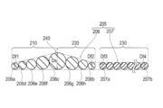
- the coil member 200 includes a first linear body 206 disposed on the distal end side in the axial direction, and a second line disposed on the proximal end side in the axial direction from the first linear body 206. And a body 207.
- first covering layer 310 and a second covering layer 320 described later is omitted.
- the coil member 200 has a first region 210, a second region 220, and a third region 230 from the distal end toward the proximal end along the axial direction of the core wire 100.
- the first region 210 of the coil member 200 and the second region 220 of the coil member 200 are formed by the first linear body 206.
- the first linear body 206 is formed of one continuous member.
- one continuous member means that the linear body is formed as one member at the stage where it is prepared as a member for forming the coil member 200.
- a linear body formed by joining a plurality of members made of different materials in advance before forming the coil member 200 is included in “one continuous member”, but the first linear body 206 What is fixed (connected) at the stage of forming the coil member 200, such as the second linear body 207, is not included in “one continuous member”.
- the third region 230 of the coil member 200 includes a second linear body 207 that is different from the first linear body 206.
- the first linear body 206 and the second linear body 207 are fixed via an intermediate fixing portion 170 described later.
- the first region 210 of the coil member 200 increases from the distal end by increasing the outer diameter of the first linear body 206 forming the coil member 200 from the distal end toward the proximal end.
- a first inclined portion whose outer shape increases toward the proximal end is formed.
- the first region 210 of the coil member 200 forms a tapered portion in which the outer shape of the coil member 200 gradually decreases toward the distal end side.
- the outer diameter of the first linear body 206 forming the coil member 200 decreases from the distal end toward the proximal end, thereby reducing the outer shape from the distal end toward the proximal end.
- Two inclined portions are formed.
- the second region 220 of the coil member 200 forms a tapered portion in which the outer shape of the coil member 200 gradually decreases toward the proximal end side.
- the boundary portion between the first region 210 of the coil member 200 and the second region 220 of the coil member 200 forms a maximum outer shape portion 240 where the outer shape of the coil member 200 is the largest. That is, the outer shape of the coil member 200 is largest at the boundary between the proximal end of the first region 210 and the distal end of the second region 220.
- region 230 of the coil member 200 forms the linear part extended in the substantially constant external shape from the front-end
- the outer shape of the coil member 200 is represented by a tangent line (outer shape line) 200A connecting the outer surfaces of the linear bodies 205 forming the coil member 200 (see FIGS. 2 and 3). .
- the outer shape of the coil member 200 is the outer shape of the coil member 200 in a state where the first coating layer 310 and the second coating layer 320 described later are not disposed, that is, the outer shape of the coil member 200 in the state shown in FIG. means.
- the inner surface of the coil member 200 is represented by a tangent line 200B connecting the inner surfaces of the linear bodies 205 forming the coil member 200.
- the first linear body 206 that forms the first region 210 of the coil member 200 and the second region 220 of the coil member 200 has higher contrast than the second linear body 207 that forms the third region 230 of the coil member 200. have. For this reason, the first region 210 and the second region 220 have higher contrast than the third region 230.
- the first linear body 206 can be formed of, for example, a material having radiopacity.
- a material having radiopacity for example, platinum, gold, silver, titanium, tungsten, cobalt, or an alloy containing these can be used.
- the second linear body 207 can be formed of a material that is less radiopaque than the first linear body 206.
- a material for example, stainless steel, a superelastic alloy, or the like can be used.
- the material forming the linear bodies 206 and 207 may be subjected to processing such as quenching.
- the core wire 100 includes a first core part 110 disposed on the distal end side in the axial direction and a first core part 110 disposed on the proximal end side of the first core part 110 and connected to the first core part 110. 2 core portions 120.
- the first core portion 110 of the core wire 100 includes a first tapered portion 111 formed in a tapered shape whose outer shape decreases toward the distal end, and a proximal end side of the first tapered portion 111.
- a second tapered portion 112 formed in a tapered shape whose outer shape decreases toward the base end, and a constant outer shape portion 113 formed on the base end side of the second tapered portion 112 and extending in a substantially constant outer shape. ,have.
- the maximum outer shape where the outer shape is the largest in the first core portion 110 At the boundary between the first taper portion 111 of the first core portion 110 of the core wire 100 and the second taper portion 112 of the first core portion 110 of the core wire 100, the maximum outer shape where the outer shape is the largest in the first core portion 110. A portion 140 is formed.
- At least a part of the first tapered portion 111 of the first core portion 110 is disposed so as to overlap with the first region 210 of the coil member 200 in the circumferential direction of the core wire 100. Further, at least a part of the second tapered portion 112 of the first core portion 110 is disposed so as to overlap the second region 220 of the coil member 200 in the circumferential direction of the core wire 100. Further, the maximum outer shape portion 140 of the first core portion 110 is disposed so as to overlap the maximum outer shape portion 240 of the coil member 200 in the circumferential direction of the core wire 100.
- a constituent material of the first core portion 110 of the core wire 100 for example, a Ni—Ti alloy, stainless steel, or a superelastic alloy can be used.
- the second core portion 120 of the core wire 100 has a distal end portion 121 formed in a tapered shape whose outer shape becomes smaller toward the distal end side, and a large diameter formed on the proximal end side of the distal end portion 121. Part 122.
- the second core portion 120 of the core wire 100 for example, stainless steel or a cobalt-based alloy can be used.
- the first core part 110 and the second core part 120 may be formed of the same or the same kind of metal material (for example, the same main metal material in the alloy).
- the first core part 110 and the second core part 120 can be connected by a method such as welding.
- the core wire 100 can be configured by a single continuous member, or can be configured by connecting three or more members.
- the linear body 205 forming the coil member 200 and the first core portion 110 of the core wire 100 are fixed to the distal end side fixing portion 160 and the proximal end side relative to the distal end side fixing portion 160. It is fixed via three fixing portions of a base end side fixing portion 180 disposed on the base end side with respect to the portion 170 and the intermediate fixing portion 170.
- the distal-end-side fixing portion 160 includes the distal end portion of the core wire 100 (the distal end portion of the first core portion 110) 101 and the portion disposed at the most distal end of the first linear body 206 forming the coil member 200 (of the coil member 200).
- the portion 206a that forms the tip of the first region 210 is fixed.
- the front end side fixing portion 160 is formed in a taper shape that is curved in a convex shape toward the front end and has a smaller outer shape.
- the length in the axial direction of the distal end side fixing portion 160, the curvature curved toward the distal end side, and the like are not particularly limited, and can be changed as appropriate.
- the intermediate fixing part 170 fixes three members of the first linear body 206, the second linear body 207, and the first core part 110.
- the intermediate fixing portion 170 is the portion that is disposed at the most proximal end in the first linear body 206 that forms the coil member 200 (the portion that forms the proximal end portion of the second region 220 of the coil member 200).
- 206b and the base end part of the 2nd taper part 112 of the 1st core part 110 of the core wire 100 are being fixed.
- the intermediate fixing portion 170 includes a portion (a portion that forms the proximal end portion of the second region 220 of the coil member 200) 206b disposed most proximally in the first linear body 206, and a second linear body.
- a portion 207a disposed at the most distal end (portion forming the distal end portion of the third region 230 of the coil member 200) 207a is fixed.
- the proximal end side fixing portion 180 is a portion (the portion that forms the proximal end portion of the third region 230 of the coil member 200) 207b disposed at the most proximal end in the second linear body 207 that forms the coil member 200;
- the fixed outer shape portion 113 of the first core portion 110 of the core wire 100 is fixed.
- Each fixing part 160, 170, 180 can be formed with, for example, solder or adhesive shaped into a predetermined shape.
- a first coating layer 310 is provided on the outer surface of the coil member 200.
- the first coating layer 310 is made of, for example, a cellulose polymer material, a polyethylene oxide polymer material, a maleic anhydride polymer material (for example, a maleic anhydride copolymer such as a methyl vinyl ether-maleic anhydride copolymer). ), Acrylamide polymer materials (eg, polyacrylamide, polyglycidyl methacrylate-dimethylacrylamide (PGMA-DMAA) block copolymer), water-soluble nylon, polyvinyl alcohol, polyvinyl pyrrolidone, etc. can do.
- PGMA-DMAA polyglycidyl methacrylate-dimethylacrylamide
- a second coating layer 320 is provided on the outer surface of the second core portion 120 of the core wire 100.
- the second coating layer 320 can be formed of, for example, a fluorine resin such as PTFE or ETFE.
- each of the coating layers 310 and 320 is not particularly limited, but can be formed to about 0.1 to 100 ⁇ m, for example.
- the inner diameter d1 (the inner diameter formed by the coil member 200) d1 of the first region 210 of the coil member 200 is equal to the inner diameter d2 of the second region 220 of the coil member 200 and the third region 230 of the coil member 200. It is substantially the same as the inner diameter d3.
- inner diameters are substantially the same.
- the flexibility of each region 210, 220, 230 of the coil member 200 is the same to the extent that it does not become significantly different due to the influence of the different inner diameters.
- the difference in dimensions based on manufacturing tolerances is included in the substantially same range.
- substantially the same regarding dimensions other than the inner diameter described in the present specification means that they are the same as long as the effects of the invention are not impaired, and at least the differences in dimensions based on manufacturing tolerances are substantially the same. Shall be included.
- the first region 210 of the coil member 200 is formed by five portions 206a, 206d, 206e, 206f, and 206c arranged from the tip side to the middle portion of the first linear body 206.
- the portion 206c arranged at the most proximal end includes a portion on the distal end side in the first region 210 and a portion on the proximal end side in the second region 220. .
- each part of the first linear body 206 forming the second region 220 of the coil member 200 decreases from the distal end toward the proximal end.
- the second region 220 of the coil member 200 is formed by four portions 206c, 206g, 206h, and 206b arranged from the intermediate portion to the proximal end side in the first linear body 206.
- the portion 206c disposed at the most distal end of the second region 220 includes a portion on the distal end side in the first region 210, and a portion on the proximal end side. It is included in the second region 220.
- an intermediate fixing portion 170 is sandwiched between the proximal end side of the portion 206b that forms the proximal end portion of the second region 220 of the coil member 200 (see FIG. 2), and the second wire A portion 207 a that forms the tip of the third region 230 of the coil member 200 is disposed in the cylindrical body 207.
- the second linear body 207 forming the third region 230 of the coil member 200 has substantially the same outer diameter in each part. Therefore, the outer shape of the third region 230 of the coil member 200 is linear along the axial direction.
- the outer diameter Df1 of the portion 206a that forms the distal end portion of the first region 210 of the coil member 200 in the first linear body 206 forms the proximal end portion of the second region 220 of the coil member 200 in the first linear body 206. It is substantially the same as the outer diameter Df2 of the portion 206b to be operated.
- the outer diameter Df2 of the portion 206b that forms the proximal end portion of the second region 220 of the coil member 200 in the first linear body 206 is equal to the distal end portion of the third region 230 of the coil member 200 in the second linear body 207. Is substantially the same as the outer diameter Df3 of the portion 207a forming the. Since the second linear body 207 has substantially the same outer diameter at each part in the axial direction, the outside of the portion 207b that forms the proximal end portion of the third region 230 of the coil member 200 in the second linear body 207.
- the diameter Df4 is substantially the same as the outer diameter Df3 of the portion 207a that forms the tip of the third region 230 of the coil member 200 in the second linear body 207. That is, in the present embodiment, the outer diameters Df1, Df2, Df3, and Df4 of each part of the linear body 205 are formed substantially the same.
- the guide wire 10 has the following effects when the outer diameters Df1, Df2, Df3, and Df4 of each part of the linear body 205 are defined as described above.
- the outer diameter Df2 of the portion 206b that forms the proximal end portion of the second region 220 of the coil member 200 in the first linear body 206 forms the distal end portion of the third region 230 of the coil member 200 in the second linear body 207.
- This is substantially the same as the outer diameter Df3 of the portion 207a.
- the guide wire 10 can suppress an increase in physical property step (rigid change width) at the boundary between the first linear body 206 and the second linear body 207. Accordingly, the guide wire 10 can prevent the core wire 100 from being broken or broken at the boundary portion between the first linear body 206 and the second linear body 207.
- the portion 206 a that forms the tip of the first region 210 of the coil member 200 in the first linear body 206 has the smallest outer diameter as compared with the other portions of the first linear body 206. For this reason, when the guide wire 10 is pushed into the constriction S from the distal end side of the coil member 200, the portion 206a positioned at the forefront of the coil member 200 is prevented from riding on the other portion 206d adjacent to the proximal end side. it can.
- the outer diameter Df1 of the portion 206a that forms the distal end portion of the first region 210 of the coil member 200, and in the first linear body 206, the proximal end portion of the second region 220 of the coil member 200 is formed.
- the outer diameter Df2 of the portion 206b can be formed to be 0.02 mm to 0.1 mm, for example.
- the outer diameter Ds of the portion 206c forming the maximum outer shape portion 240 of the coil member 200 in the first linear body 206 can be formed to 0.04 mm to 0.2 mm, for example.
- the outer diameters of the first linear body 206 other than the above-described parts are the lengths in the axial direction of the first region 210 and the second region 220, and the first linear body of the portion forming the first region 210 and the second region 220. It can be formed in an arbitrary size according to the number of windings 206.
- the outer diameters Df3 and Df4 of the portions 207a and 207b forming the third region 230 of the coil member 200 in the second linear body 207 are formed to 0.02 mm to 0.1 mm, similar to the outer diameters Df1 and Df2. can do.
- the maximum outer shape portion 240 of the coil member 200 has a substantially central position in the axial direction of the portion 206 c formed with the largest outer diameter in the first linear body 206 (maximum in the first linear body 206. It is formed at a position on the extension line of the perpendicular H that passes through the center portion c1 of the portion 206c forming the outer shape portion 240 and is orthogonal to the axis of the core wire 100.
- the maximum outer shape 240 of the coil member 200 extends along the spiral shape of the coil member 200. That is, on the cross-sectional views shown in FIGS. 2 and 3, the maximum outer shape portion 240 extends in a spiral manner obliquely from the upper side of the drawing toward the lower side of the drawing.
- the external dimension Dm along the direction orthogonal to the axial direction of the maximum external part 240 is a perpendicular H passing through the center part c1 of the part 206c forming the maximum external part 240 in the first linear body 206. Is defined as the length of a range delimited by a virtual line 200A indicating the outer shape of the coil member 200 (see FIG. 3).
- the outer dimension Dm along the direction orthogonal to the axial direction of the maximum outer shape portion 240 is, for example, the outer diameter of the maximum outer shape portion 240 when the axis orthogonal cross section of the maximum outer shape portion 240 is formed in a circle.
- the external dimension Dm along the direction orthogonal to the axial direction of the maximum external part 240 can be formed to 0.28 mm to 0.80 mm, for example.
- the outer dimension D1 of the first region 210 of the coil member 200 can be formed such that the minimum portion on the distal end side is 0.25 mm to 0.61 mm, and the maximum portion on the proximal end side is 0.27 mm. It can be formed to ⁇ 0.79 mm.
- the outer dimension D2 of the second region 220 of the coil member 200 can be formed such that, for example, the maximum portion on the distal end side is 0.27 mm to 0.79 mm, and the minimum portion on the proximal end side is 0.25 mm. It can be formed to 0.61 mm.
- the outer dimension D3 of the third region 230 of the coil member 200 can be formed with a constant size along the axial direction, for example, 0.24 mm to 0.60 mm.
- the inner diameter d1 of the first region 210 of the coil member 200, the inner diameter d2 of the second region 220 of the coil member 200, and the inner diameter d3 of the third region 230 of the coil member 200 are, for example, 0.2 mm to 0.4 mm. Can be formed.
- region 210 of the coil member 200 may be formed longer than length L2 along the axial direction of the 2nd area
- the guide wire 10 can be formed in a more acute angle (a shape that is sharp at the tip) with the tip shape of the coil member 200 facing the tip side.
- the length L3 along the axial direction of the third region 230 of the coil member 200 is, for example, the sum of the length L1 along the axial direction of the first region 210 and the length L2 along the axial direction of the second region 220. It can be formed longer than the length.
- the ratio of the length L3 along the axial direction of the third region 230 to the total length along the axial direction of the coil member 200 increases. Thereby, the part in which the first region 210 and the second region 220 are formed in the coil member 200 is formed closer to the distal end side of the coil member 200.
- the third region 230 has a length of 50% or more of the total length along the axial direction of the coil member 200. Preferably formed.
- the length along the axial direction of the coil member 200 can be formed to 191 mm to 310 mm, for example.
- the length L1 along the axial direction of the first region 210 can be formed to 0.5 mm to 30 mm, for example.
- the length L2 along the axial direction of the second region 220 can be formed to 0.5 mm to 30 mm, for example.
- the length L3 along the axial direction of the third region 230 can be formed to 190 mm to 250 mm, for example.
- the length L1 along the axial direction of the first region 210 of the coil member 200 is preferably formed longer than the length L2 along the axial direction of the second region 220 of the coil member 200.
- FIGS. 5 and 6 are schematic sectional views showing the state before and after the guide wire 10 is pushed through the stenosis S formed in the blood vessel and penetrated.
- the guide wire 10 when the surgeon or the like pushes the guide wire 10 toward the narrowed portion S toward the distal end side, the guide wire 10 is pushed into the narrowed portion S from the distal end side of the first region 210 of the coil member 200. It is. In the coil member 200 of the guide wire 10, since the outer shape of the first region 210 located at the foremost end becomes smaller from the proximal end side toward the distal end side, the pushing force against the narrowed portion S is increased. Thereby, the surgeon or the like can smoothly push the guide wire 10 into the narrowed portion S.
- the surgeon or the like pushes the guide wire 10 further into the constriction S, thereby bringing the second region 220 of the coil member 200 into the constriction S following the first region 210 of the coil member 200. To enter.
- the second region 220 of the coil member 200 of the guide wire 10 decreases toward the proximal end side, the second region 220 and the constricted portion S are moved when the second region 220 moves in the constricted portion S.
- the penetration resistance that the second region 220 of the coil member 200 receives from the constriction S is reduced.
- the surgeon or the like can easily push the second region 220 following the first region 210 of the coil member 200 and the third region 230 following the second region 220 into the stenosis S,
- the guide wire 10 can be smoothly moved in the narrowed portion S.
- the guide wire 10 controls (shapes) the outer shape of the coil member 200 by adjusting the outer diameter of the first linear body 206 forming the coil member 200, the regions 210 and 220 of the coil member 200 are controlled. , 230 can maintain the inner diameters d1, d2, and d3 at a predetermined size, thereby ensuring flexibility. Further, in the guide wire 10, the inner diameter d1 of the first region 210 of the coil member 200 and the inner diameter d2 of the second region 220 of the coil member 200 are substantially the same.
- the guide wire 10 is not formed with an excessively large inner diameter at the maximum outer shape portion 240 of the coil member 200, an increase in the outer shape of the maximum outer shape portion 240 accompanying an increase in the inner diameter of the coil member 200 is suppressed. For this reason, when the coil member 200 penetrates the constriction part S, the stress concentration which the largest external part 240 of the coil member 200 receives is reduced. As a result, the guide wire 10 is further improved in the pushability of the guide wire 10 with respect to the narrowed portion S, and the first linear body 206 (206c) forming the maximum outer shape portion 240 rides on the proximal end side. Can be prevented.
- the guide wire 10 includes the core wire 100 and the coil member 200 fixed to at least the distal end portion 101 of the core wire 100, and the coil member 200 is in the axial direction of the core wire 100.
- the first region 210, the second region 220, and the third region 230 are provided from the distal end to the proximal end along the line.
- the outer diameter of the first linear body 206 forming the coil member 200 increases from the distal end toward the proximal end, thereby increasing the outer shape from the distal end toward the proximal end.
- region 220 of the coil member 200 reduces the outer diameter of the 1st linear body 206 which forms the coil member 200 toward a base end from a front-end
- a second inclined portion whose outer shape becomes smaller toward the outside is formed, and a boundary portion between the first region 210 of the coil member 200 and the second region 220 of the coil member 200 has a maximum outer shape portion 240 where the outer shape of the coil member 200 is largest.
- the inner diameter d1 formed by the coil member 200 in the first region 210 of the coil member 200 is substantially the same as the inner diameter d2 formed by the coil member 200 in the second region 220 of the coil member 200.
- the guide wire 10 configured as described above can increase the pushing force against the constriction S by the first region 210 of the coil member 200.
- the second region 220 of the coil member 200 reduces the penetration resistance that the guide wire 10 receives from the constriction S when being pushed into the constriction S following the first region 210 of the coil member 200. Therefore, the guide wire 10 has further improved penetrability with respect to the narrowed portion S.
- the guide wire 10 adjusts the outer diameter of the first linear body 206 forming the coil member 200 to control (shape) the outer shape of the coil member 200 while maintaining the inner diameter formed by the coil member 200. Therefore, flexibility can be secured.
- the inner diameter formed by the coil member is On the distal end side of the first inclined portion and the proximal end side of the second inclined portion, it must be made smaller than other portions of the coil member. A portion of the coil member that has a smaller inner diameter than the other portions reduces the flexibility of the coil member.
- the guide wire 10 according to the present embodiment can prevent the reduction in flexibility of the coil member 200 as described above.
- the inner diameter formed by the coil member 200 is maintained substantially the same in the first region 210, the second region 220, and the maximum outer shape portion 240 formed at the boundary between the first region 210 and the second region 220. Therefore, when forming the maximum outer shape portion 240 of the coil member 200, the outer shape of the maximum outer shape portion 240 of the coil member 200 does not become excessively large. Thereby, when the coil member 200 penetrates the constriction part S, the guide wire 10 can suppress stress concentration on the maximum outer shape part 240. For this reason, the guide wire 10 has a further improved pushability to the narrowed portion S, and can further prevent the portion 207c forming the maximum outer shape portion 240 of the first linear body 206 from running on the proximal end side. .
- the core wire 100 is formed in a tapered shape whose outer shape becomes smaller toward the tip, and at least a part of the first taper is arranged so as to overlap the first region 210 of the coil member 200 in the circumferential direction of the core wire 100.
- the second taper portion is formed in a tapered shape such that the outer shape becomes smaller toward the base 111 and at least a portion thereof overlaps with the second region 220 of the coil member 200 in the circumferential direction of the core wire 100. 112.
- the first taper portion 111 of the core wire 100 disposed so as to overlap the first region 210 of the coil member 200 in the circumferential direction of the core wire 100 is pushed into the constricted portion S together with the first region 210 of the coil member 200. Improve sexiness.
- the second taper portion 112 of the core wire 100 that is arranged so as to overlap the second region 220 of the coil member 200 in the circumferential direction of the core wire 100 is the first taper on the core wire 100 when the guide wire 10 is pushed into the constriction S. It is possible to mitigate the occurrence of stress concentration in the one taper portion 111.
- the core wire 100 forms a maximum outer shape 140 at the boundary between the first tapered portion 111 of the core wire 100 and the second tapered portion 112 of the core wire 100.
- the guide wire 10 has an intermediate fixing portion 170 that fixes the coil member 200 and the proximal end portion of the second tapered portion 112 of the core wire 100.
- the intermediate fixing portion 170 has a proximal end portion of the second taper portion 112 formed at the first taper portion 111 and the second taper portion 112 that is relatively less rigid than the other portions of the core wire 100 with respect to the coil member 200. By fixing (connecting), the core wire 100 is prevented from being broken or broken at the proximal end portion of the second tapered portion 112.
- the guide wire 10 is formed such that the length L1 along the axial direction of the first region 210 of the coil member 200 is longer than the length L2 along the axial direction of the second region 220 of the coil member 200. For this reason, the length L1 along the axial direction of the 1st area
- the guide wire 10 has a length L3 along the axial direction of the third region 230 of the coil member 200 and a length L1 along the axial direction of the first region 210 of the coil member 200 and the length L3 of the second region 220 of the coil member 200. It is formed longer than the length obtained by adding the length L2 along the axial direction. For this reason, the portion of the coil member 200 where the first region 210 and the second region 220 are formed is formed closer to the tip side of the coil member 200. As a result, the guide wire 10 is effectively improved in penetrability with respect to the narrowed portion S due to the first region 210 and the second region 220 arranged on the distal end side of the coil member 200.
- the guide wire 10 includes an outer diameter of a portion 206b that forms a proximal end portion of the second region 220 of the coil member 200 in the first linear body 206, and a third region of the coil member 200 in the second linear body 207.
- the outer diameter of the portion 207a that forms the tip of 230 is formed to be substantially the same.
- the coil member 200 is caused by the difference in outer diameter between the portions 206b and 207a from the proximal end portion of the second region 220 to the distal end portion of the third region 230 whose outer shape decreases from the distal end side toward the proximal end side. It is possible to suppress an increase in the physical property step (change width of rigidity). Thereby, the guide wire 10 can prevent breakage such as breakage at the boundary portion between the proximal end portion of the second region 220 of the coil member 200 and the distal end portion of the third region 230 of the coil member 200.
- the guide wire 10 also has a distal end side fixing portion 160 that fixes the distal end portion 101 of the core wire 100 and the coil member 200.
- the distal-end-side fixing portion 160 is formed in a tapered shape that is curved in a convex shape toward the distal end and whose outer shape becomes smaller toward the distal end. As described above, in the guide wire 10, the distal end fixing portion 160 is tapered toward the distal end side, so that the pushing force against the narrowed portion S is further improved.
- the distal end side fixing portion 160 has a shape that is convexly curved toward the distal end, when the guide wire 10 is moved in the living body, a living organ such as a blood vessel is moved from the distal end of the guide wire 10. Can be protected.
- the first linear body 206 that forms the first region 210 of the coil member 200 and the second region 220 of the coil member 200 is higher than the second linear body 207 that forms the third region 230 of the coil member 200.
- first linear body 206 forming the first region 210 of the coil member 200 and the second region 220 of the coil member 200 is formed of one continuous member. By forming the first region 210 and the second region 220 with one continuous member, the coil member 200 can be manufactured easily.
- the guide wire according to the present invention has been described through the embodiments.
- the present invention is not limited to the contents described in the specification, and can be appropriately changed based on the description of the scope of claims. is there.
- the number of windings of the linear body forming the coil member and the outer diameter of each part of the linear body are not particularly limited as long as the first region, the second region, and the third region can be formed in the coil member.
- the shape of the third region of the coil member is exemplified as a shape having a constant outer shape, but the shape of the third region is not limited to such a shape.
- the third region may be formed by an inclined portion in which the outer diameter of the linear body decreases toward the base end and the outer shape decreases toward the base end.
- the maximum outer shape of the third region is preferably formed to be equal to or smaller than the base end portion of the second region.
- the inner diameter of the third region may not be the same as the inner diameters of the first region and the second region, and may not be a constant size along the axial direction.
- each part of the coil member for example, the length along the axial direction of each region
- the dimensions of each part of the core wire for example, the length along the axial direction of each part
- etc. are limited to those described in the specification. It can be changed as appropriate.
- the material forming the coil member and the material forming the core wire are not limited to those exemplified in the specification, and can be appropriately changed.
- the guide wire may have a structure in which the core wire is wound in a plurality of layers such as double or triple around the core wire.
- region of a coil member are formed of the coil member arrange
- the internal diameter which a coil member forms is an internal diameter which the coil member arrange
- the coil member may not be formed of one continuous member in which the linear body forming the first region and the linear body forming the second region are formed.
- the first region and the maximum outer shape portion are formed by one linear body
- the second region is formed by another linear body
- the first region is formed by one linear body
- the second region and You may form a largest external shape part with another linear body.
- the shape of the core wire is not limited by the shape described with reference to the drawings.
- the core wire may have a shape extending substantially linearly along the axial direction in which the first tapered portion and the second tapered portion are not formed.
Landscapes
- Health & Medical Sciences (AREA)
- Life Sciences & Earth Sciences (AREA)
- Biophysics (AREA)
- Pulmonology (AREA)
- Engineering & Computer Science (AREA)
- Anesthesiology (AREA)
- Biomedical Technology (AREA)
- Heart & Thoracic Surgery (AREA)
- Hematology (AREA)
- Animal Behavior & Ethology (AREA)
- General Health & Medical Sciences (AREA)
- Public Health (AREA)
- Veterinary Medicine (AREA)
- Media Introduction/Drainage Providing Device (AREA)
Abstract
Le problème décrit par la présente invention est de fournir un fil-guide qui garantit la souplesse et qui est apte à réduire la résistance au passage lors du passage à travers une lésion telle qu'une section rétrécie. La solution selon l'invention porte sur un élément de bobine (200) disposé dans un fil-guide (10) qui présente une première région (210), une deuxième région (220) et une troisième région (230) localisées le long du sens axial d'un fil cœur (100) de son extrémité de pointe jusqu'à son extrémité de base. La première région forme une première section angulaire présentant une augmentation de son contour externe depuis l'extrémité de pointe vers l'extrémité de base, en augmentant le diamètre externe d'un premier corps linéaire (206) qui forme l'élément de bobine dans un sens allant de l'extrémité de pointe vers l'extrémité de base. La deuxième région forme une seconde section angulaire présentant une baisse dans son contour externe depuis l'extrémité de pointe vers l'extrémité de base, en réduisant le diamètre externe du premier corps linéaire qui forme l'élément de bobine dans un sens allant de l'extrémité de pointe vers l'extrémité de base. La limite entre la première et la deuxième région forme la section de contour externe maximal (240), au niveau de laquelle le contour externe de l'élément de bobine est le plus grand. Le diamètre interne (d1) de l'élément de bobine dans la première région est sensiblement identique au diamètre interne (d2) de l'élément de bobine dans la deuxième région.
Applications Claiming Priority (2)
| Application Number | Priority Date | Filing Date | Title |
|---|---|---|---|
| JP2017009761A JP2020039377A (ja) | 2017-01-23 | 2017-01-23 | ガイドワイヤ |
| JP2017-009761 | 2017-01-23 |
Publications (1)
| Publication Number | Publication Date |
|---|---|
| WO2018135534A1 true WO2018135534A1 (fr) | 2018-07-26 |
Family
ID=62908614
Family Applications (1)
| Application Number | Title | Priority Date | Filing Date |
|---|---|---|---|
| PCT/JP2018/001235 WO2018135534A1 (fr) | 2017-01-23 | 2018-01-17 | Fil-guide |
Country Status (2)
| Country | Link |
|---|---|
| JP (1) | JP2020039377A (fr) |
| WO (1) | WO2018135534A1 (fr) |
Citations (4)
| Publication number | Priority date | Publication date | Assignee | Title |
|---|---|---|---|---|
| JP2001212243A (ja) * | 2000-02-02 | 2001-08-07 | Ci Medeikku:Kk | 医療用ガイドワイヤ |
| JP2007135645A (ja) * | 2005-11-14 | 2007-06-07 | Terumo Corp | ガイドワイヤ |
| JP2014100300A (ja) * | 2012-11-20 | 2014-06-05 | Asahi Intecc Co Ltd | ガイドワイヤ |
| JP2017196368A (ja) * | 2016-04-28 | 2017-11-02 | 株式会社エフエムディ | 医療用ガイドワイヤ |
-
2017
- 2017-01-23 JP JP2017009761A patent/JP2020039377A/ja active Pending
-
2018
- 2018-01-17 WO PCT/JP2018/001235 patent/WO2018135534A1/fr active Application Filing
Patent Citations (4)
| Publication number | Priority date | Publication date | Assignee | Title |
|---|---|---|---|---|
| JP2001212243A (ja) * | 2000-02-02 | 2001-08-07 | Ci Medeikku:Kk | 医療用ガイドワイヤ |
| JP2007135645A (ja) * | 2005-11-14 | 2007-06-07 | Terumo Corp | ガイドワイヤ |
| JP2014100300A (ja) * | 2012-11-20 | 2014-06-05 | Asahi Intecc Co Ltd | ガイドワイヤ |
| JP2017196368A (ja) * | 2016-04-28 | 2017-11-02 | 株式会社エフエムディ | 医療用ガイドワイヤ |
Also Published As
| Publication number | Publication date |
|---|---|
| JP2020039377A (ja) | 2020-03-19 |
Similar Documents
| Publication | Publication Date | Title |
|---|---|---|
| JP5020630B2 (ja) | ガイドワイヤ | |
| JP5770676B2 (ja) | ガイドワイヤ | |
| WO2016047499A1 (fr) | Fil-guide | |
| EP2389973A1 (fr) | Cathéter à ballonnet | |
| EP2415497A1 (fr) | Fil-guide | |
| JP2004230142A (ja) | ガイドワイヤ | |
| JP2008194185A (ja) | ガイドワイヤ | |
| JPWO2014162393A1 (ja) | ガイドワイヤ | |
| JP2011167387A (ja) | ガイドワイヤ | |
| JP2024500098A (ja) | 医療用カテーテルおよびその製造方法 | |
| US20120191070A1 (en) | Guidewire | |
| JP2013039305A (ja) | ガイドワイヤ | |
| US20150119757A1 (en) | Coil body and guide wire | |
| JP5874885B1 (ja) | 医療用ガイドワイヤ | |
| JP2018079246A (ja) | ガイドワイヤ | |
| JP5473677B2 (ja) | ガイドワイヤ | |
| WO2018135534A1 (fr) | Fil-guide | |
| JP3179894U (ja) | カテーテル | |
| WO2018181177A1 (fr) | Fil de guidage | |
| JP2013192914A (ja) | ガイドワイヤ | |
| JP2018108119A (ja) | ガイドワイヤおよび医療用コイル | |
| JP2012176190A (ja) | ガイドワイヤ | |
| JP6053696B2 (ja) | ガイドワイヤ | |
| JP4405252B2 (ja) | 医療用ワイヤ | |
| JPWO2016047555A1 (ja) | ガイドワイヤおよびガイドワイヤの製造方法 |
Legal Events
| Date | Code | Title | Description |
|---|---|---|---|
| 121 | Ep: the epo has been informed by wipo that ep was designated in this application |
Ref document number: 18741198 Country of ref document: EP Kind code of ref document: A1 |
|
| NENP | Non-entry into the national phase |
Ref country code: DE |
|
| 122 | Ep: pct application non-entry in european phase |
Ref document number: 18741198 Country of ref document: EP Kind code of ref document: A1 |
|
| NENP | Non-entry into the national phase |
Ref country code: JP |