WO2018131358A1 - パワーステアリング装置 - Google Patents
パワーステアリング装置 Download PDFInfo
- Publication number
- WO2018131358A1 WO2018131358A1 PCT/JP2017/044315 JP2017044315W WO2018131358A1 WO 2018131358 A1 WO2018131358 A1 WO 2018131358A1 JP 2017044315 W JP2017044315 W JP 2017044315W WO 2018131358 A1 WO2018131358 A1 WO 2018131358A1
- Authority
- WO
- WIPO (PCT)
- Prior art keywords
- nut
- output pulley
- power steering
- screw
- steering apparatus
- Prior art date
- Legal status (The legal status is an assumption and is not a legal conclusion. Google has not performed a legal analysis and makes no representation as to the accuracy of the status listed.)
- Ceased
Links
Images


Classifications
-
- B—PERFORMING OPERATIONS; TRANSPORTING
- B62—LAND VEHICLES FOR TRAVELLING OTHERWISE THAN ON RAILS
- B62D—MOTOR VEHICLES; TRAILERS
- B62D5/00—Power-assisted or power-driven steering
- B62D5/04—Power-assisted or power-driven steering electrical, e.g. using an electric servo-motor connected to, or forming part of, the steering gear
- B62D5/0421—Electric motor acting on or near steering gear
-
- B—PERFORMING OPERATIONS; TRANSPORTING
- B62—LAND VEHICLES FOR TRAVELLING OTHERWISE THAN ON RAILS
- B62D—MOTOR VEHICLES; TRAILERS
- B62D5/00—Power-assisted or power-driven steering
- B62D5/04—Power-assisted or power-driven steering electrical, e.g. using an electric servo-motor connected to, or forming part of, the steering gear
- B62D5/0442—Conversion of rotational into longitudinal movement
- B62D5/0445—Screw drives
- B62D5/0448—Ball nuts
-
- F—MECHANICAL ENGINEERING; LIGHTING; HEATING; WEAPONS; BLASTING
- F16—ENGINEERING ELEMENTS AND UNITS; GENERAL MEASURES FOR PRODUCING AND MAINTAINING EFFECTIVE FUNCTIONING OF MACHINES OR INSTALLATIONS; THERMAL INSULATION IN GENERAL
- F16H—GEARING
- F16H25/00—Gearings comprising primarily only cams, cam-followers and screw-and-nut mechanisms
- F16H25/18—Gearings comprising primarily only cams, cam-followers and screw-and-nut mechanisms for conveying or interconverting oscillating or reciprocating motions
- F16H25/20—Screw mechanisms
- F16H25/22—Screw mechanisms with balls, rollers, or similar members between the co-operating parts; Elements essential to the use of such members
- F16H25/2204—Screw mechanisms with balls, rollers, or similar members between the co-operating parts; Elements essential to the use of such members with balls
- F16H25/2214—Screw mechanisms with balls, rollers, or similar members between the co-operating parts; Elements essential to the use of such members with balls with elements for guiding the circulating balls
-
- F—MECHANICAL ENGINEERING; LIGHTING; HEATING; WEAPONS; BLASTING
- F16—ENGINEERING ELEMENTS AND UNITS; GENERAL MEASURES FOR PRODUCING AND MAINTAINING EFFECTIVE FUNCTIONING OF MACHINES OR INSTALLATIONS; THERMAL INSULATION IN GENERAL
- F16H—GEARING
- F16H55/00—Elements with teeth or friction surfaces for conveying motion; Worms, pulleys or sheaves for gearing mechanisms
- F16H55/32—Friction members
- F16H55/36—Pulleys
- F16H55/48—Pulleys manufactured exclusively or in part of non-metallic material, e.g. plastics
Definitions
- the present invention relates to a power steering device.
- Patent Document 1 discloses a power steering device that transmits a driving force of an electric motor to a ball screw mechanism via an input pulley, a belt, and an output pulley, and converts it into an axial thrust of a rack shaft.
- the output pulley is fastened to the nut of the ball screw mechanism by a screw.
- An object of the present invention is to provide a power steering device that can reduce the maximum generated stress of an output pulley.
- the output pulley of the power steering apparatus includes a fastened portion around the screw insertion hole of the hub portion.
- the to-be-fastened part has an inferior angle of the relative angle between the tangent to the inner surface of the output pulley and the rotation axis of the nut in the axial section of the output pulley passing through the rotation axis of the nut.
- the portion that gradually decreases toward 45 ° and becomes 45 ° is defined as a boundary portion between the hub portion and the winding portion, the region is located on the inner side of the boundary portion in the radial direction, and the screw This is the region that overlaps the head of the screw in the radial direction.
- the maximum generated stress of the output pulley can be reduced.
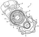
- FIG. 1 is an axial cross-sectional view of a power steering device 1 according to Embodiment 1.
- FIG. It is S1-S1 arrow sectional drawing of FIG. 4 is an axial sectional view of a ball screw mechanism 4 passing through a rotation axis of a nut 11.
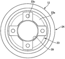
- FIG. 3 is a front view of the output pulley 12.
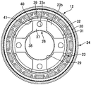
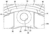
- FIG. 3 is a rear view of the output pulley 12.
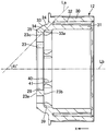
- FIG. 2 is an axial sectional view of an output pulley 12 passing through a rotation axis of a nut 11.
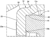
- FIG. FIG. 6 is a sectional view in the axial direction of the main part of the ball screw mechanism 4 showing a state in which the X-axis positive direction end portion of the nut 11 is press-fitted inside each centering portion 41. It is a principal part enlarged view of FIG. It is a principal part enlarged view of FIG.
- FIG. 1 is a cross-sectional view in the axial direction of the power steering device 1 according to the first embodiment, and FIG.
- the power steering device 1 is mounted on a vehicle that uses an engine as a power source.
- the power steering apparatus 1 includes a steering mechanism 2, an electric motor 3, a ball screw mechanism 4, and a housing 5.
- the steering mechanism 2 steers the front wheels that are steered wheels.
- the steering mechanism 2 has a rack bar (steering shaft) 6 extending in the vehicle body width direction.
- the rack bar 6 is formed using a ferrous metal material such as a steel material.
- the rack bar 6 moves in the vehicle body width direction according to the rotation of the steering shaft connected to the steering wheel (not shown).
- the ends of the pair of tie rods 7 and 7 are connected to both ends of the rack bar 6.
- the front wheels are connected to the pair of tie rods 7,7.
- the electric motor 3 applies a steering force to the steering mechanism 2.
- the electric motor 3 is, for example, a three-phase brushless motor.
- the output of the electric motor 3 is controlled by a motor control unit (not shown) in accordance with the driver's steering torque and vehicle speed input to the steering wheel (not shown).
- An input pulley 9 is attached to the motor shaft 8 of the electric motor 3.
- One end of a belt (transmission member) 10 is wound around the outer periphery of the input pulley 9.
- the ball screw mechanism 4 is provided between the steering mechanism 2 and the electric motor 3.
- the ball screw mechanism 4 converts the rotational force of the electric motor 3 into the propulsive force of the steering mechanism 2.
- the ball screw mechanism 4 has a nut 11.
- the nut 11 is formed in a substantially cylindrical shape surrounding the rack bar 6.
- An output pulley 12 is fixed to the outer periphery of the nut 11.
- the rotation axis of the output pulley 12 coincides with the rotation axis of the nut 11.
- the rotation axes of the nut 11 and the output pulley 12 are offset from the rotation axis of the input pulley 9 in the radial direction of the input pulley 9.
- the outer diameter of the output pulley 12 is larger than the outer diameter of the input pulley 9.
- the other end of the belt 10 is wound around the outer periphery of the output pulley 12.
- the nut 11 is supported so as to be rotatable with respect to the housing 5 and immovable in the axial direction.
- a ball circulation groove 13 is formed on the inner periphery of the nut 11 and the outer periphery of the rack bar 6.
- a plurality of balls 14 are arranged in the ball circulation groove 13. Each ball 14 moves to one end side or the other end side of the ball circulation groove 13 according to the rotation of the nut 11.
- the ball 14 that has reached one end or the other end of the ball circulation groove 13 by the rotation of the nut 11 is returned to the other end or one end of the ball circulation groove 13 via a tube (see FIG. 3) 4a that is a circulation mechanism.
- the housing 5 is formed by die casting using an aluminum alloy.
- the housing 5 includes a steering mechanism housing 15, a motor housing 16, and a ball screw mechanism housing 17.
- the steering mechanism housing 15 accommodates a part of the steering mechanism 2 (a part of the steering shaft, the rack bar 6 and the like) inside.
- the inner ends of the dust boots 18 in the vehicle width direction are fixed to both ends of the steering mechanism housing 15 in the vehicle width direction.
- the dust boot 18 is formed in a bellows ring shape using rubber or the like.
- the outer end of the dust boot 18 in the vehicle width direction is fixed to the tie rod 7.
- the motor housing 16 houses the electric motor 3 therein.
- the ball screw mechanism housing 17 accommodates the ball screw mechanism 4 therein.
- the X axis is set in the axial direction of the rack bar 6, the direction from the steering mechanism 2 side to the ball screw mechanism 4 side is the X axis positive direction, the X axis orthogonal direction is the radial direction, and the X axis.
- the surrounding direction is defined as the circumferential direction.
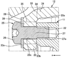
- FIG. 3 is an axial sectional view of the ball screw mechanism 4 passing through the rotation axis of the nut 11.
- the central portion of the nut 11 in the X-axis direction is formed with a smaller diameter than both ends in the X-axis direction.
- a spiral nut-side ball screw groove 19 is formed on the inner periphery of the central portion in the X-axis direction.
- a spiral rack bar side ball screw groove (steering shaft side ball screw groove) 20 is formed on the outer periphery of the rack bar 6.
- the nut side ball screw groove 19 and the rack bar side ball screw groove 20 constitute a ball circulation groove 13.
- An inner race 21a of the ball bearing 21 is integrally formed at the end of the nut 11 in the negative X-axis direction.
- the ball bearing 21 supports the nut 11 with respect to the ball screw mechanism housing 17 so as to be rotatable in the circumferential direction.
- the ball bearing 21 includes an inner race 21a, an outer race 21b, and a ball 21c.
- the outer race 21b is fixed to the ball screw mechanism housing 17.
- the ball 21c is interposed between the inner race 21a and the outer race 21b.
- Four female screw portions 22 are formed at the end of the nut 11 in the positive direction of the X axis.
- the female screw portion 22 extends along the X-axis direction.
- the female screw portions 22 are arranged at 90 ° intervals in the circumferential direction.
- FIG. 4 is a front view of the output pulley 12
- FIG. 5 is a rear view of the output pulley 12
- FIG. 6 is an axial sectional view of the output pulley 12 passing through the rotation axis of the nut 11.
- the output pulley 12 is formed in a bottomed cup shape by injection molding using a resin material.
- a disk gate (diaphragm gate) type is adopted as a gate at the time of injection molding.
- the output pulley 12 has a hub portion 23 and a winding portion 24.
- the hub portion 23 is located at the end of the output pulley 12 in the positive X axis direction.
- the hub portion 23 is formed in a substantially annular disk shape.
- Screw insertion holes 23c penetrate through the hub portion 23 in the X-axis direction.
- the screw insertion holes 23c are arranged at 90 ° intervals in the circumferential direction.
- a screw 25 is inserted into each screw insertion hole 23c from the X axis positive direction side.
- the screw 25 fastens the output pulley 12 and the nut 11.
- the screw 25 has a head portion 26 and a shaft portion 27.
- the outer shape of the head 26 is substantially circular when viewed from the X-axis direction.
- the shaft portion 27 is formed with a male screw portion (a thread groove of a male screw) 27a.
- the male screw portion 27a is fitted into the female screw portion 22 of the nut 11 by a screw action.
- a washer 28 is interposed between the screw 25 and the outer surface (side surface in the X-axis positive direction) 23a of the hub portion 23.
- the washer 28 is formed in an annular disk shape.
- the outer diameter of the washer 28 is larger than the outer diameter of the head 26.
- the hub portion 23 has a rack bar insertion hole (steering shaft insertion hole) 29 at the radial center thereof. The rack bar 6 passes through the rack bar insertion hole 29.
- the winding part 24 extends from the outer periphery of the hub part 23 in the negative X-axis direction.
- the winding part 24 includes an outer cylinder part 30, an inner cylinder part 31, and 16 bridge parts 32.
- the outer cylinder part 30 is formed in a cylindrical shape.
- a belt 10 is wound around the outer cylinder portion 30.
- the inner cylinder part 31 is located on the radially inner side of the outer cylinder part 30.
- the inner cylinder part 31 is formed in a cylindrical shape having a smaller diameter than the outer cylinder part 30.
- the X-axis positive direction end of the outer cylinder part 30 is connected to the inner cylinder part 31.
- the bridge part 32 extends between the outer cylinder part 30 and the inner cylinder part 31 in the radial direction, and connects the outer cylinder part 30 and the inner cylinder part 31.
- the bridge portions 32 are arranged at 22.5 ° intervals in the circumferential direction.
- the winding part 24 and the hub part 23 are smoothly connected by the connection part 33.
- the connecting portion 33 is formed in an arc shape.
- the minor angle of the angle (relative angle) formed by the tangent line La of the inner surface 33 a of the connection portion 33 and the rotation axis Lb of the nut 11 gradually increases from the rotation axis Lb toward the radially outer side.
- the portion that becomes 45 ° and becomes 45 ° is defined as a boundary portion 34 between the hub portion 23 and the winding portion 24. Further, a region around the screw insertion hole 23c of the hub portion 23 and overlapping with the head portion 26 of the screw 25 in the radial direction is defined as a fastened portion 35.
- the fastened portion 35 is a portion that receives the axial force of the screw 25 from the head portion 26 of the screw 25 when the output pulley 12 and the nut 11 are fastened by the screw 25.
- the fastened portion 35 is located on the radially inner side of the boundary portion 34.
- the outer peripheral edge of the washer 28 overlaps the boundary portion 34 in the radial direction.
- the hub portion 23 of the output pulley 12 has a protruding portion 36 on its inner side surface (X-axis negative direction side surface) 23b.
- the protrusion 36 protrudes from the inner surface 23b by a predetermined length in the negative direction of the X axis.
- the protrusion 36 has four radial protrusions 37 and an annular protrusion 38.
- the radial protrusions 37 are arranged at 90 ° intervals in the circumferential direction according to the position of the screw insertion hole 23c. Each radial protrusion 37 abuts substantially flush with the end of the nut 11 in the positive direction of the X axis.
- the radial protrusions 37 extend in the radial direction and have a shape that includes the entire projected area of the fastened portion 35 when viewed from the X-axis direction.
- the annular protrusion 38 is arranged at the opening edge of the rack bar insertion hole 29.
- the annular protrusion 38 is connected to the radially inner end of each radial protrusion 37.
- the hub portion 23 has four thin portions 39 and eight thick portions 40 on the inner side surface 23b.
- the thin portion 39 is a predetermined region portion radially outside the screw insertion hole 23c of the radial protrusion 37.
- the width (circumferential length) of the thin portion 39 is wider than the width of the radial protrusion 37.
- the thick portion 40 is disposed at the same radial position as the thin portion 39.
- the thick part 40 is adjacent to the thin part 39 in the circumferential direction.
- the thick portion 40 protrudes by a predetermined length in the negative X-axis direction from the thin portion 39, that is, the radial protrusion 37. That is, when the material thickness of the hub portion 23 in the X-axis direction is thick, the thickness of the thick portion 40 is larger than that of the thin portion 39 (radial protruding portion 37).
- Each thick portion 40 has a centering portion 41 on the radially inner side.
- the centering portion 41 has an arc shape that is convex toward the inside in the radial direction. As shown in FIG.
- each centering portion 41 is in pressure contact with the outer peripheral surface 11 a of the end portion of the nut 11 in the X-axis positive direction. That is, the X-axis positive direction end portion of the nut 11 is press-fitted inside the centering portion 41.
- FIG. 8 is an enlarged view of the main part of FIG. 5
- FIG. 9 is an enlarged view of the main part of FIG.
- the boundary portion connecting the hub portion and the winding portion overlaps the fastened portion in the radial direction.
- the boundary portion is a portion where the axial sectional area of the output pulley changes abruptly, that is, a portion where the stiffness changes suddenly. For this reason, in the conventional output pulley, stress concentration occurs in the fastened portion, and the maximum generated stress in the fastened portion increases.
- the output pulley 12 of the first embodiment is formed of a resin material with the aim of reducing the weight and cost. Resin-made output pulleys have a lower allowable stress (fatigue strength) than metal-made output pulleys.
- the fastened portion 35 is disposed radially inward from the boundary portion 34. That is, the boundary portion 34 whose axial cross-sectional area changes suddenly escapes radially outward from the fastened portion 35 that receives the axial force from the head portion 26 of the screw 25. Therefore, since there is no portion where the axial cross-sectional area changes suddenly in the fastened portion 35, the stress generated by the axial force of the screw 25 can be dispersed, and the stress concentration can be reduced. Thereby, the maximum generated stress in the fastened portion 35 can be reduced.
- a predetermined region on the radially outer side of the screw insertion hole 23c is a thin portion 39, and the axial cross-sectional area of the thin portion 39 is the same as that of the thick portion 40 adjacent to the thin portion 39 in the circumferential direction. It was smaller than the axial cross-sectional area.
- a washer 28 is provided between the fastened portion 35 and the head 26 of the screw 25. Thereby, it can suppress that the to-be-fastened part 35 formed with the resin material is damaged by the contact with the head 26.
- the outer periphery of the washer 28 overlaps the boundary portion 34 in the radial direction of the screw 25.
- the output pulley 12 includes a centering portion 41 that is located on the radially inner side of the winding portion 24 and that contacts the outer peripheral surface 11a of the nut 11.
- the centering portion 41 comes into contact with the outer peripheral surface 11a of the nut 11, so that the rotation axis of the output pulley 12 can be brought closer to the rotation axis of the nut 11 (alignment). Action). Thereby, the workability at the time of assembly can be improved, for example, the radial alignment between the screw insertion hole 23c and the female screw portion 22 can be facilitated.
- the centering portion 41 has an arc shape that is convex inward in the radial direction of the output pulley 12.
- the fastened portion 35 has a protruding portion 36 that protrudes in the negative direction of the X axis from the portion adjacent to the fastened portion 35 on the inner side surface 23b of the hub portion 23.
- the molding accuracy of the output pulley 12 affects the assembly accuracy on the contact surface with the nut 11, but each fastened portion 35 projects to the nut 11 side from the other adjacent portion (inner side surface 23b). Therefore, it can suppress that the shaping
- FIG. since the assembly accuracy depends only on the molding accuracy of the protruding portion 36, for example, when the output pulley 12 is removed from the mold after injection molding, the assembly accuracy is improved even if pressing marks remain by pressing other parts. Has no effect. Therefore, both ease of manufacture and assembly accuracy can be improved.
- the output pulley 12 has an annular protrusion 38 that surrounds the rack bar insertion hole 29 into which the rack bar 6 is inserted. Since the axial cross-sectional area around the rack bar insertion hole 29 is made uniform by the annular protrusion 38, the degree of cooling shrinkage around the rack bar insertion hole 29 is reduced in the cooling shrinkage process after injection molding of the output pulley 12. It can be made uniform.
- the winding portion 24 is formed in a cylindrical shape, and an outer cylindrical portion 30 around which the belt 10 is wound, an inner cylindrical portion 31 that is formed in a cylindrical shape and is provided inside the outer cylindrical portion 30, and extends in a radial direction of the nut 11. And a bridge portion 32 that connects the outer cylinder portion 30 and the inner cylinder portion 31.
- the winding portion 24 desirably has a higher cylindricity from the viewpoint of noise suppression and vibration suppression when the output pulley 12 rotates.
- the winding part has a solid structure
- the cooling contraction of the outer cylinder part 40 can be suppressed by the bridge part 32. Therefore, the cylindricity of the outer cylinder part 30 can be improved as compared with the case where the winding part has a solid structure.
- a region (connecting portion 33) between the hub portion 23 and the winding portion 24 in the axial section of the output pulley 12 passing through the rotation axis of the nut 11 is formed in an arc shape. That is, by smoothly connecting the hub portion 23 and the winding portion 24 with the arc-shaped connection portion 33, the change in the axial cross-sectional area becomes gentle, so that the stress concentration between the hub portion 23 and the winding portion 24 Can be relaxed.
- the output pulley 12 is formed by disk gate type injection molding. In the pin gate type, since a weld line (bath) is formed, there is a concern about a decrease in synthesis due to a decrease in adhesion strength at the interface. On the other hand, since the weld line is less likely to occur in the disk gate type, the rigidity of the output pulley 12 can be improved compared to other methods such as a pin gate.
- the power steering device includes a steered shaft that steers the steered wheels by moving in the axial direction as the steering wheel rotates; and a nut that is annularly provided so as to surround the steered shaft;
- a groove, a nut-side ball screw groove that is provided on the inner peripheral side of the nut, has a spiral groove shape, and forms a ball circulation groove together with the steered shaft-side ball screw groove, and the ball circulation groove
- a ball screw mechanism comprising: a plurality of balls provided; and a circulation mechanism that circulates the plurality of balls from one end side to the other end side of the ball circulation groove;
- a hub portion that is provided so as to face one end surface of the nut and is formed of a resin material
- the output pulley includes a fastened portion around the screw insertion hole of the hub portion.
- the fastened portion has an inferior angle of a relative angle between a tangent to the inner surface of the output pulley and an axis of rotation of the nut in the axial section of the output pulley passing through the rotation axis of the nut.
- the power steering device includes a washer between the fastened portion and the head of the screw.
- the washer is provided such that an outer peripheral edge thereof overlaps the boundary portion in a radial direction of the screw.
- the output pulley includes a centering portion that is provided inside the output pulley and contacts the outer peripheral surface of the nut.
- the centering portion has an arc shape that is convex inward in the radial direction of the output pulley.
- the fastened portion includes a protruding portion that protrudes closer to the nut side than a portion adjacent to the fastened portion in the rotation axis direction of the nut.
- the output pulley includes a turning shaft insertion hole that is provided in the hub portion and into which the turning shaft is inserted, and the protruding portion is the turning shaft.
- An annular protrusion is formed in an annular shape so as to surround the insertion hole.
- the winding portion is formed in a cylindrical shape and the outer cylindrical portion around which the transmission member is wound, and is formed in a cylindrical shape and provided inside the outer cylindrical portion. And a bridge portion formed so as to extend in the radial direction of the nut and connecting the outer cylinder portion and the inner cylinder portion.
- a region between the hub portion and the winding portion in the axial section of the output pulley passing through the rotation axis of the nut is It is formed in an arc shape.
- the output pulley is formed by disk gate type injection molding.
- the power steering device includes a steered shaft that steers the steered wheels by moving in the axial direction along with the rotation of the steering wheel; and annularly surrounds the steered shaft.
- a ball screw mechanism that moves the steered shaft relative to the nut in the rotational axis direction of the nut, the nut being provided on an outer peripheral side of the steered shaft, and having a spiral groove shape.
- a ball screw mechanism comprising: a plurality of balls provided in the ball circulation groove; and a circulation mechanism for circulating the plurality of balls from one end side to the other end side of the ball circulation groove;
- a hub portion that is provided so as to face one end face of the nut in the axial direction and formed of a resin material; a winding portion that is provided integrally with the hub portion and formed in a cylindrical shape with the resin material;
- An output pulley having a screw insertion hole provided in the hub portion and penetrating in the rotational axis direction of the nut; a screw inserted into the screw insertion hole, wherein the head and a thread groove of a male screw are provided And a screw that fastens the nut and the output pulley; an input pulley that
- the output pulley is a thin wall provided in a predetermined region outside the screw insertion hole in the radial direction of the nut, where the material thickness of the output pulley in the rotation axis direction of the nut is the thickness of the output pulley. And a thick portion provided in a region adjacent to the thin portion in a direction around the rotation axis of the nut.
- the radial dimension that is the distance from the rotation axis of the nut in the thick part is the same as the radial dimension in the thin part.
- the output pulley includes a centering portion that is provided inside the output pulley and contacts the outer peripheral surface of the nut.
- the centering portion has an arc shape that is convex inward in the radial direction of the output pulley.
- the output pulley includes a fastened portion in a region overlapping with a screw head in a radial direction of the screw, and the fastened portion includes the nut. In the direction of the rotation axis, a protruding portion that protrudes to the nut side from a portion adjacent to the fastened portion is provided on the side of the hub portion that faces the nut.
- the output pulley includes a turning shaft insertion hole that is provided in the hub portion and into which the turning shaft is inserted, and the protruding portion is the turning shaft.
- An annular protrusion is formed in an annular shape so as to surround the insertion hole.
Landscapes
- Engineering & Computer Science (AREA)
- General Engineering & Computer Science (AREA)
- Mechanical Engineering (AREA)
- Chemical & Material Sciences (AREA)
- Combustion & Propulsion (AREA)
- Transportation (AREA)
- Manufacturing & Machinery (AREA)
- Power Steering Mechanism (AREA)
- Pulleys (AREA)
- Transmission Devices (AREA)
Abstract
出力プーリの最大発生応力を低減できるパワーステアリング装置を提供する。 パワーステアリング装置の出力プーリは、ハブ部のスクリュ挿入孔周りに被締結部を備える。被締結部は、ナットの回転軸線を通る出力プーリの軸方向断面における出力プーリの内側面の接線とナットの回転軸線との相対角のうちの劣角が、ナットの回転軸線側から径方向外側に向かって徐々に小さくなり、45°となる部分をハブ部と巻き掛け部との間の境界部としたとき、径方向において境界部よりも内側に位置する領域であって、かつ、スクリュの径方向においてスクリュの頭部とオーバーラップする領域である。
Description
本発明は、パワーステアリング装置に関する。
特許文献1には、電動モータの駆動力を、入力プーリ、ベルトおよび出力プーリを介してボールねじ機構に伝達し、ラック軸の軸方向推力に変換するパワーステアリング装置が開示されている。出力プーリは、スクリュによってボールねじ機構のナットと締結されている。
上記従来のパワーステアリング装置は、出力プーリにおいてスクリュの頭部からスクリュの軸力を受ける部分に軸方向断面積が急変する箇所が存在するため、当該箇所に応力集中が発生し、最大発生応力が大きくなるという問題があった。
本発明の目的の一つは、出力プーリの最大発生応力を低減できるパワーステアリング装置を提供することにある。
本発明の目的の一つは、出力プーリの最大発生応力を低減できるパワーステアリング装置を提供することにある。
本発明の一実施形態におけるパワーステアリング装置の出力プーリは、ハブ部のスクリュ挿入孔周りに被締結部を備える。被締結部は、ナットの回転軸線を通る出力プーリの軸方向断面における出力プーリの内側面の接線とナットの回転軸線との相対角のうちの劣角が、ナットの回転軸線側から径方向外側に向かって徐々に小さくなり、45°となる部分をハブ部と巻き掛け部との間の境界部としたとき、径方向において境界部よりも内側に位置する領域であって、かつ、スクリュの径方向においてスクリュの頭部とオーバーラップする領域である。
よって、本発明の一実施形態にあっては、出力プーリの最大発生応力を低減できる。
〔実施形態1〕
図1は実施形態1のパワーステアリング装置1の軸方向断面図、図2は図1のS1-S1矢視断面図である。
パワーステアリング装置1は、エンジンを動力源とする車両に搭載されている。パワーステアリング装置1は、操舵機構2、電動モータ3、ボールねじ機構4およびハウジング5を有する。
操舵機構2は、転舵輪である前輪を転舵させる。操舵機構2は、車体幅方向に延びるラックバー(転舵軸)6を有する。ラックバー6は、鋼材等の鉄系金属材料を用いて形成されている。ラックバー6は、図外のステアリングホイールと接続されたステアリングシャフトの回転に応じて車体幅方向に移動する。ラックバー6の両端には、1対のタイロッド7,7の端部が接続されている。1対のタイロッド7,7には前輪が接続されている。
電動モータ3は、操舵機構2に操舵力を付与する。電動モータ3は、例えば三相ブラシレスモータである。電動モータ3は、図外のステアリングホイールに入力されたドライバの操舵トルクや車両速度に応じて図外のモータコントロールユニットにより出力が制御される。電動モータ3のモータシャフト8には、入力プーリ9が取り付けられている。入力プーリ9の外周には、ベルト(伝達部材)10の一端側が巻き掛けられている。
ボールねじ機構4は、操舵機構2と電動モータ3との間に設けられている。ボールねじ機構4は、電動モータ3の回転力を操舵機構2の推進力に変換する。ボールねじ機構4は、ナット11を有する。ナット11は、ラックバー6を包囲する略円筒状に形成されている。ナット11の外周には、出力プーリ12が固定されている。出力プーリ12の回転軸線はナット11の回転軸線と一致する。ナット11および出力プーリ12の回転軸線は、入力プーリ9の回転軸線に対して、入力プーリ9の径方向にオフセットして配置されている。出力プーリ12の外径は入力プーリ9の外径よりも大きい。出力プーリ12の外周には、ベルト10の他端が巻き掛けられている。ナット11は、ハウジング5に対し回転可能、かつ、軸方向移動不能に支持されている。ナット11の内周およびラックバー6の外周には、ボール循環溝13が形成されている。ボール循環溝13内には、複数のボール14が配置されている。各ボール14は、ナット11の回転に応じてボール循環溝13の一端側または他端側へ移動する。ナット11の回転によりボール循環溝13の一端または他端に達したボール14は、循環機構であるチューブ(図3参照)4aを介してボール循環溝13の他端または一端へと戻される。
ハウジング5は、アルミニウム合金を用いて金型鋳造により形成されている。ハウジング5は、操舵機構ハウジング15、モータハウジング16およびボールねじ機構ハウジング17を有する。操舵機構ハウジング15は、内部に操舵機構2の一部(ステアリングシャフトの一部、ラックバー6等)を収容する。操舵機構ハウジング15の車幅方向両端には、ダストブーツ18の車幅方向内側端が固定されている。ダストブーツ18は、ゴム等を用いて蛇腹環状に形成されている。ダストブーツ18の車幅方向外側端は、タイロッド7と固定されている。モータハウジング16は、内部に電動モータ3を収容する。ボールねじ機構ハウジング17は、内部にボールねじ機構4を収容する。
次に、実施形態1のナット11および出力プーリ12を詳細に説明する。なお、図1において、ラックバー6の軸線方向にX軸を設定し、操舵機構2の側からボールねじ機構4の側へ向かう方向をX軸正方向、X軸直交方向を径方向、X軸周りの方向を周方向と規定する。
図3は、ナット11の回転軸線を通るボールねじ機構4の軸方向断面図である。
ナット11のX軸方向中央部は、X軸方向両端部よりも小径に形成されている。ナット11において、X軸方向中央部の内周には、螺旋状のナット側ボールねじ溝19が形成されている。一方、ラックバー6の外周には、螺旋状のラックバー側ボールねじ溝(転舵軸側ボールねじ溝)20が形成されている。ナット側ボールねじ溝19およびラックバー側ボールねじ溝20は、ボール循環溝13を構成する。ナット11のX軸負方向端には、ボールベアリング21のインナレース21aが一体に形成されている。ボールベアリング21は、ボールねじ機構ハウジング17に対しナット11を周方向回転可能に支持する。ボールベアリング21は、インナレース21a、アウタレース21bおよびボール21cを有する。アウタレース21bはボールねじ機構ハウジング17に固定されている。ボール21cはインナレース21aおよびアウタレース21b間に介在する。ナット11のX軸正方向端には、4個の雌ねじ部22が形成されている。雌ねじ部22は、X軸方向に沿って延びる。各雌ねじ部22は、周方向に90°間隔で配置されている。
図4は出力プーリ12の正面図、図5は出力プーリ12の背面図、図6はナット11の回転軸線を通る出力プーリ12の軸方向断面図である。
出力プーリ12は、樹脂材料を用いた射出成形により、有底カップ状に形成されている。実施形態1では、射出成形時のゲートとして、ディスクゲート(ダイアフラムゲート)式を採用している。出力プーリ12は、ハブ部23および巻き掛け部24を有する。ハブ部23は、出力プーリ12のX軸正方向端に位置する。ハブ部23は、略環状円盤形に形成されている。ハブ部23には、4個のスクリュ挿入孔23cがX軸方向に貫通する。各スクリュ挿入孔23cは、周方向に90°間隔で配置されている。各スクリュ挿入孔23cには、X軸正方向側からスクリュ25が挿入されている。スクリュ25は、出力プーリ12とナット11を締結する。スクリュ25は、頭部26および軸部27を有する。頭部26の外形はX軸方向から見たとき略円形である。軸部27には、雄ねじ部(雄ねじのねじ溝)27aが形成されている。雄ねじ部27aは、ねじ作用によりナット11の雌ねじ部22に嵌め込まれる。スクリュ25とハブ部23の外側面(X軸正方向側面)23aとの間には、座金28が介在する。座金28は環状円盤形に形成されている。座金28の外径は、頭部26の外径よりも大きい。ハブ部23は、その径方向中心にラックバー挿入孔(転舵軸挿入孔)29を有する。ラックバー挿入孔29には、ラックバー6が貫通する。
出力プーリ12は、樹脂材料を用いた射出成形により、有底カップ状に形成されている。実施形態1では、射出成形時のゲートとして、ディスクゲート(ダイアフラムゲート)式を採用している。出力プーリ12は、ハブ部23および巻き掛け部24を有する。ハブ部23は、出力プーリ12のX軸正方向端に位置する。ハブ部23は、略環状円盤形に形成されている。ハブ部23には、4個のスクリュ挿入孔23cがX軸方向に貫通する。各スクリュ挿入孔23cは、周方向に90°間隔で配置されている。各スクリュ挿入孔23cには、X軸正方向側からスクリュ25が挿入されている。スクリュ25は、出力プーリ12とナット11を締結する。スクリュ25は、頭部26および軸部27を有する。頭部26の外形はX軸方向から見たとき略円形である。軸部27には、雄ねじ部(雄ねじのねじ溝)27aが形成されている。雄ねじ部27aは、ねじ作用によりナット11の雌ねじ部22に嵌め込まれる。スクリュ25とハブ部23の外側面(X軸正方向側面)23aとの間には、座金28が介在する。座金28は環状円盤形に形成されている。座金28の外径は、頭部26の外径よりも大きい。ハブ部23は、その径方向中心にラックバー挿入孔(転舵軸挿入孔)29を有する。ラックバー挿入孔29には、ラックバー6が貫通する。
巻き掛け部24は、ハブ部23の外周からX軸負方向に延びる。巻き掛け部24は、外筒部30、内筒部31および16個のブリッジ部32を有する。外筒部30は、円筒状に形成されている。外筒部30にはベルト10が巻き掛けられている。内筒部31は、外筒部30の径方向内側に位置する。内筒部31は、外筒部30よりも小径の円筒状に形成されている。外筒部30のX軸正方向端は内筒部31と接続する。ブリッジ部32は、外筒部30および内筒部31間を径方向に延び、外筒部30と内筒部31とを接続する。各ブリッジ部32は、周方向に22.5°間隔で配置されている。
巻き掛け部24およびハブ部23間は、接続部33により滑らかに接続されている。ナット11の回転軸線を通る出力プーリ12の軸方向断面において、接続部33は、円弧状に形成されている。ここで、図6において、接続部33の内側面33aの接線Laとナット11の回転軸線Lbとがなす角度(相対角)のうちの劣角が、回転軸線Lbから径方向外側に向かって徐々に小さくなり、45°となる部分をハブ部23と巻き掛け部24との間の境界部34と規定する。また、ハブ部23のスクリュ挿入孔23c周りの領域であって、スクリュ25の頭部26と径方向にオーバーラップする領域を被締結部35と規定する。被締結部35は、出力プーリ12とナット11をスクリュ25により締結したとき、スクリュ25の頭部26からスクリュ25の軸力を受ける部分である。被締結部35は、境界部34よりも径方向内側に位置する。座金28の外周縁は、境界部34と径方向にオーバーラップする。
巻き掛け部24およびハブ部23間は、接続部33により滑らかに接続されている。ナット11の回転軸線を通る出力プーリ12の軸方向断面において、接続部33は、円弧状に形成されている。ここで、図6において、接続部33の内側面33aの接線Laとナット11の回転軸線Lbとがなす角度(相対角)のうちの劣角が、回転軸線Lbから径方向外側に向かって徐々に小さくなり、45°となる部分をハブ部23と巻き掛け部24との間の境界部34と規定する。また、ハブ部23のスクリュ挿入孔23c周りの領域であって、スクリュ25の頭部26と径方向にオーバーラップする領域を被締結部35と規定する。被締結部35は、出力プーリ12とナット11をスクリュ25により締結したとき、スクリュ25の頭部26からスクリュ25の軸力を受ける部分である。被締結部35は、境界部34よりも径方向内側に位置する。座金28の外周縁は、境界部34と径方向にオーバーラップする。
出力プーリ12のハブ部23は、その内側面(X軸負方向側面)23bに、突出部36を有する。突出部36は、内側面23bからX軸負方向へ所定長さ突出する。突出部36は、4個の放射状突出部37および環状突出部38を有する。各放射状突出部37は、スクリュ挿入孔23cの位置に合わせて、周方向に90°間隔で配置されている。各放射状突出部37は、ナット11のX軸正方向端と略面一に当接する。放射状突出部37は、放射方向に延び、X軸方向から見たとき、被締結部35の投影面積を全て含む形状を有する。環状突出部38は、ラックバー挿入孔29の開口縁に配置されている。環状突出部38は、各放射状突出部37の径方向内側端と接続する。
ハブ部23は、その内側面23bに、4個の薄肉部39および8個の厚肉部40を有する。薄肉部39は、放射状突出部37のスクリュ挿入孔23cよりも径方向外側の所定領域部分である。薄肉部39の幅(周方向長さ)は、放射状突出部37の幅よりも広い。厚肉部40は、薄肉部39と同じ径方向位置に配置されている。厚肉部40は、薄肉部39と周方向に隣接する。厚肉部40は、薄肉部39、すなわち放射状突出部37よりもX軸負方向へ所定長さ突出する。つまり、X軸方向におけるハブ部23の材料厚さを肉厚としたとき、厚肉部40の肉厚は、薄肉部39(放射状突出部37)よりも大きく形成されている。
各厚肉部40は、径方向内側にセンタリング部41を有する。センタリング部41は、径方向内側に向かって凸形状となる円弧形状を有する。図7に示すように、各センタリング部41は、ナット11のX軸正方向端部の外周面11aと圧接する。つまり、ナット11のX軸正方向端部は、センタリング部41の内側に圧入されている。
次に、実施形態1のパワーステアリング装置1の作用効果を説明する。
図8は図5の要部拡大図、図9は図3の要部拡大図である。
ナット11と出力プーリ12とをスクリュ25で締結する際、スクリュ25の締め付けトルクを大きくしていくと、出力プーリ12の被締結部35のうち、ナット11と当接する部分(頭部26およびナット11間に挟まれた部分)は圧縮変形し、ナット11と当接していない部分(頭部26およびナット11間に挟まれていない部分)はX軸負方向へ曲げ変形する。従来の出力プーリでは、ハブ部と巻き掛け部とを接続する境界部が、被締結部と径方向にオーバーラップしている。境界部は出力プーリの軸方向断面積が急激に変化する部分、つまり剛性が急変する部分である。このため、従来の出力プーリでは、被締結部に応力集中が発生し、被締結部における最大発生応力が大きくなる。ここで、実施形態1の出力プーリ12は、軽量化やコストダウン等を狙いとし、樹脂材料で形成されている。樹脂製の出力プーリは金属製の出力プーリに比べて許容応力(疲労強度)が低いため、最大発生応力が大きいと強度上の不利益(亀裂による破損や耐久性の低下)を招きやすい。
これに対し、実施形態1の出力プーリ12では、被締結部35を境界部34よりも径方向内側に配置した。つまり、軸方向断面積が急変する境界部34を、スクリュ25の頭部26から軸力を受ける被締結部35よりも径方向外側へ逃した。よって、被締結部35に軸方向断面積が急変する箇所が存在しないため、スクリュ25の軸力により発生する応力を分散でき、応力集中を緩和できる。これにより、被締結部35における最大発生応力を低減できる。
実施形態1の出力プーリ12は、スクリュ挿入孔23cの径方向外側の所定領域を薄肉部39とし、薄肉部39の軸方向断面積を、薄肉部39と周方向に隣接する厚肉部40の軸方向断面積よりも小さくした。これにより、スクリュ25の軸力を大きく受けるスクリュ挿入孔23c周りの領域において、軸方向断面積の変化を抑制できる。よって、スクリュ25の軸力により発生する応力を分散でき、応力集中を緩和できる。これにより、被締結部35における最大発生応力を低減できる。
被締結部35とスクリュ25の頭部26との間に座金28を有する。これにより、樹脂材料で形成された被締結部35が頭部26との接触によって傷付くのを抑制できる。
座金28は、その外周縁がスクリュ25の径方向において境界部34とオーバーラップする。ハブ部23に対する座金28の接触面積を大きくすることにより、座金28からハブ部23に作用する単位面積あたりの軸力(面圧)を低減でき、ハブ部23の変形を抑制できる。
出力プーリ12は、巻き掛け部24の径方向内側に位置し、ナット11の外周面11aと当接するセンタリング部41を有する。ナット11と出力プーリ12とをスクリュ25で締結する際、センタリング部41がナット11の外周面11aと当接することにより、ナット11の回転軸線に対し出力プーリ12の回転軸線を近づけられる(調芯作用)。これにより、スクリュ挿入孔23cと雌ねじ部22との径方向の位置合わせを容易化できる等、組み付け時の作業性を向上できる。
センタリング部41は、出力プーリ12の径方向において内側に向かって凸形状となる円弧形状を有する。円弧の頂点がナット11の外周面11aと当接することにより、両者の接触部分は線接線に近づくため、接触面の成形精度の影響を抑制できる。また、ナット11を各センタリング部41の内側に圧入する際の接触面積を極小化できるため、圧入荷重を低減でき、組み付け時の作業性を向上できる。
被締結部35は、ハブ部23の内側面23bにおいて、各被締結部35と隣接する部分よりもX軸負方向へ突出する突出部36を有する。ここで、出力プーリ12の成形精度は、ナット11との当接面における組み付け精度に影響を与えるが、各被締結部35は隣接する他の部分(内側面23b)よりもナット11側に突出しているため、他の部分の成形精度がナット11との当接面に対し影響を与えるのを抑制できる。つまり、組み付け精度が突出部36の成形精度のみに依存するため、例えば、射出成形後、出力プーリ12を金型から取り外す際に、他の部分を押圧して押圧痕が残っても組み付け精度には影響を与えない。よって、製作容易性および組み付け精度を共に向上できる。
出力プーリ12は、ラックバー6が挿入されるラックバー挿入孔29を包囲する環状突出部38を有する。環状突出部38によってラックバー挿入孔29周りの軸方向断面積の均一化が図られているため、出力プーリ12の射出成形後の冷却収縮過程において、ラックバー挿入孔29周りの冷却収縮度合を均一化できる。
巻き掛け部24は、筒状に形成されベルト10が巻き掛けられる外筒部30と、筒状に形成され外筒部30の内側に設けられる内筒部31と、ナット11の径方向に延び外筒部30と内筒部31とを接続するブリッジ部32と、を有する。巻き掛け部24は、出力プーリ12が回転する際の異音抑制および振動抑制の観点から、円筒度がより高い方が望ましい。ここで、仮に巻き掛け部を中実構造とした場合、出力プーリを射出成形後に金型から外したとき、巻き掛け部においてハブ部と反対側の端部が冷却収縮し、径方向内側に撓むおそれがある。これに対し、実施形態1の巻き掛け部24では、外筒部40の冷却収縮をブリッジ部32により抑制できる。よって、巻き掛け部を中実構造とした場合と比較して、外筒部30の円筒度を向上できる。
出力プーリ12は、ナット11の回転軸線を通る出力プーリ12の軸方向断面におけるハブ部23と巻き掛け部24との間の領域(接続部33)が円弧状に形成されている。つまり、ハブ部23と巻き掛け部24とを円弧状の接続部33によって滑らかに接続することにより、軸方向断面積の変化が緩やかになるため、ハブ部23および巻き掛け部24間の応力集中を緩和できる。
出力プーリ12は、ディスクゲート式の射出成形によって形成されている。ピンゲート式では、ウエルドライン(湯境)が形成されるため、界面の密着強度の低下による合成の低下が懸念される。一方、ディスクゲート式はウエルドラインが生じにくいため、ピンゲート等の他の方式に比べ、出力プーリ12の剛性を向上できる。
〔他の実施形態〕
以上、本発明を実施するための実施形態を説明したが、本発明の具体的な構成は実施形態の構成に限定されるものではなく、発明の要旨を逸脱しない範囲の設計変更等があっても本発明に含まれる。また、上述した課題の少なくとも一部を解決できる範囲、または、効果の少なくとも一部を奏する範囲において、特許請求の範囲および明細書に記載された各構成要素の任意の組み合わせ、または、省略が可能である。
伝達部材はチェーン等でもよい。
被締結部とスクリュの頭部との間に座金を設けなくてもよい。
センタリング部を厚肉部と別に設けてもよい。
以上、本発明を実施するための実施形態を説明したが、本発明の具体的な構成は実施形態の構成に限定されるものではなく、発明の要旨を逸脱しない範囲の設計変更等があっても本発明に含まれる。また、上述した課題の少なくとも一部を解決できる範囲、または、効果の少なくとも一部を奏する範囲において、特許請求の範囲および明細書に記載された各構成要素の任意の組み合わせ、または、省略が可能である。
伝達部材はチェーン等でもよい。
被締結部とスクリュの頭部との間に座金を設けなくてもよい。
センタリング部を厚肉部と別に設けてもよい。
以上説明した実施形態から把握し得る他の態様について、以下に記載する。
パワーステアリング装置は、その一つの態様において、ステアリングホイールの回転に伴い軸方向移動することにより転舵輪を転舵させる転舵軸と;前記転舵軸を包囲するように環状に設けられたナットと;前記ナットの回転軸線方向において前記ナットに対し前記転舵軸を移動させるボールねじ機構であって、前記転舵軸の外周側に設けられ、螺旋状の溝形状を有する転舵軸側ボールねじ溝と、前記ナットの内周側に設けられ、螺旋状の溝形状を有し、前記転舵軸側ボールねじ溝と共にボール循環溝を構成するナット側ボールねじ溝と、前記ボール循環溝内に設けられた複数のボールと、前記複数のボールを前記ボール循環溝の一端側から他端側へ循環させる循環機構と、を有するボールねじ機構と;前記ナットの前記回転軸線方向において前記ナットの一方側端面と対向するように設けられるとともに樹脂材料で形成されたハブ部と、前記ハブ部と一体に設けられるとともに樹脂材料で筒状に形成された巻き掛け部と、前記ハブ部に設けられるとともに前記ナットの前記回転軸線方向に貫通するスクリュ挿入孔と、を有する出力プーリと;前記スクリュ挿入孔に挿入されるスクリュであって、頭部と、雄ねじのねじ溝が形成された軸部と、を有し、前記ナットと前記出力プーリとを締結するスクリュと;前記ナットの前記回転軸線に対し径方向にオフセットして配置された入力プーリと;前記出力プーリと前記入力プーリとを跨ぐように設けられ、前記入力プーリの回転を前記出力プーリに伝達する伝達部材と;前記入力プーリを回転駆動する電動モータとを備える。前記出力プーリは、前記ハブ部の前記スクリュ挿入孔周りに被締結部を備える。前記被締結部は、前記ナットの前記回転軸線を通る前記出力プーリの軸方向断面における前記出力プーリの内側面の接線と前記ナットの前記回転軸線との相対角のうちの劣角が、前記ナットの前記回転軸線側から径方向外側に向かって徐々に小さくなり、45°となる部分を前記ハブ部と前記巻き掛け部との間の境界部としたとき、前記径方向において前記境界部よりも内側に位置する領域であって、かつ、前記スクリュの径方向において前記スクリュの前記頭部とオーバーラップする領域である。
パワーステアリング装置は、その一つの態様において、ステアリングホイールの回転に伴い軸方向移動することにより転舵輪を転舵させる転舵軸と;前記転舵軸を包囲するように環状に設けられたナットと;前記ナットの回転軸線方向において前記ナットに対し前記転舵軸を移動させるボールねじ機構であって、前記転舵軸の外周側に設けられ、螺旋状の溝形状を有する転舵軸側ボールねじ溝と、前記ナットの内周側に設けられ、螺旋状の溝形状を有し、前記転舵軸側ボールねじ溝と共にボール循環溝を構成するナット側ボールねじ溝と、前記ボール循環溝内に設けられた複数のボールと、前記複数のボールを前記ボール循環溝の一端側から他端側へ循環させる循環機構と、を有するボールねじ機構と;前記ナットの前記回転軸線方向において前記ナットの一方側端面と対向するように設けられるとともに樹脂材料で形成されたハブ部と、前記ハブ部と一体に設けられるとともに樹脂材料で筒状に形成された巻き掛け部と、前記ハブ部に設けられるとともに前記ナットの前記回転軸線方向に貫通するスクリュ挿入孔と、を有する出力プーリと;前記スクリュ挿入孔に挿入されるスクリュであって、頭部と、雄ねじのねじ溝が形成された軸部と、を有し、前記ナットと前記出力プーリとを締結するスクリュと;前記ナットの前記回転軸線に対し径方向にオフセットして配置された入力プーリと;前記出力プーリと前記入力プーリとを跨ぐように設けられ、前記入力プーリの回転を前記出力プーリに伝達する伝達部材と;前記入力プーリを回転駆動する電動モータとを備える。前記出力プーリは、前記ハブ部の前記スクリュ挿入孔周りに被締結部を備える。前記被締結部は、前記ナットの前記回転軸線を通る前記出力プーリの軸方向断面における前記出力プーリの内側面の接線と前記ナットの前記回転軸線との相対角のうちの劣角が、前記ナットの前記回転軸線側から径方向外側に向かって徐々に小さくなり、45°となる部分を前記ハブ部と前記巻き掛け部との間の境界部としたとき、前記径方向において前記境界部よりも内側に位置する領域であって、かつ、前記スクリュの径方向において前記スクリュの前記頭部とオーバーラップする領域である。
より好ましい態様では、上記態様において、前記パワーステアリング装置は、前記被締結部と前記スクリュの前記頭部との間に座金を備える。
別の好ましい態様では、上記態様のいずれかにおいて、前記座金は、その外周縁が前記スクリュの径方向において前記境界部とオーバーラップするように設けられる。
さらに別の好ましい態様では、上記態様のいずれかにおいて、前記出力プーリは、前記出力プーリの内側に設けられ、前記ナットの外周面と当接するセンタリング部を備える。
さらに別の好ましい態様では、上記態様のいずれかにおいて、前記センタリング部は、前記出力プーリの径方向において内側に向かって凸形状となる円弧形状を有する。
さらに別の好ましい態様では、上記態様のいずれかにおいて、前記被締結部は、前記ナットの前記回転軸線方向において前記被締結部と隣接する部分よりも前記ナット側に突出している突出部を、前記ハブ部の前記ナットと対向する側に備える。
さらに別の好ましい態様では、上記態様のいずれかにおいて、前記出力プーリは、前記ハブ部に設けられ前記転舵軸が挿入される転舵軸挿入孔を備え、前記突出部は、前記転舵軸挿入孔を包囲するように環状に形成された環状突出部を備える。
さらに別の好ましい態様では、上記態様のいずれかにおいて、前記巻き掛け部は、筒状に形成され前記伝達部材が巻き掛けられる外筒部と、筒状に形成され前記外筒部の内側に設けられる内筒部と、前記ナットの前記径方向に延びるように形成され前記外筒部と前記内筒部とを接続するブリッジ部と、を備える。
さらに別の好ましい態様では、上記態様のいずれかにおいて、前記出力プーリにおいて、前記ナットの前記回転軸線を通る前記出力プーリの前記軸方向断面における前記ハブ部と前記巻き掛け部との間の領域が円弧状に形成されている。
さらに別の好ましい態様では、上記態様のいずれかにおいて、前記出力プーリは、ディスクゲート式の射出成形によって形成されている。
また、他の観点から、パワーステアリング装置は、ある態様において、ステアリングホイールの回転に伴い軸方向移動することにより転舵輪を転舵させる転舵軸と;前記転舵軸を包囲するように環状に設けられたナットと;前記ナットの回転軸線方向において前記ナットに対し前記転舵軸を移動させるボールねじ機構であって、前記転舵軸の外周側に設けられ、螺旋状の溝形状を有する転舵軸側ボールねじ溝と、前記ナットの内周側に設けられ、螺旋状の溝形状を有し、前記転舵軸側ボールねじ溝と共にボール循環溝を構成するナット側ボールねじ溝と、前記ボール循環溝内に設けられた複数のボールと、前記複数のボールを前記ボール循環溝の一端側から他端側へ循環させる循環機構と、を有するボールねじ機構と;前記ナットの前記回転軸線方向において前記ナットの一方側端面と対向するように設けられるとともに樹脂材料で形成されたハブ部と、前記ハブ部と一体に設けられるとともに樹脂材料で筒状に形成された巻き掛け部と、前記ハブ部に設けられるとともに前記ナットの前記回転軸線方向に貫通するスクリュ挿入孔と、を有する出力プーリと;前記スクリュ挿入孔に挿入されるスクリュであって、頭部と、雄ねじのねじ溝が形成された軸部と、を有し、前記ナットと前記出力プーリとを締結するスクリュと;前記ナットの回転軸線に対し前記径方向にオフセットして配置された入力プーリと;前記出力プーリと前記入力プーリとを跨ぐように設けられ、前記入力プーリの回転を前記出力プーリに伝達する伝達部材と;前記入力プーリを回転駆動する電動モータとを備える。前記出力プーリは、前記ナットの前記回転軸線方向における前記出力プーリの材料厚さを出力プーリの肉厚としたとき、前記ナットの径方向において前記スクリュ挿入孔の外側の所定領域に設けられた薄肉部と、該薄肉部よりも大きい肉厚を有し、前記ナットの回転軸線周りの方向において前記薄肉部と隣接する領域に設けられた厚肉部と、を備える。前記厚肉部における前記ナットの回転軸線からの距離である半径寸法は、前記薄肉部における前記半径寸法と同じである。
好ましくは、上記態様において、前記出力プーリは、前記出力プーリの内側に設けられ、前記ナットの外周面と当接するセンタリング部を備える。
別の好ましい態様では、上記態様のいずれかにおいて、前記センタリング部は、前記出力プーリの前記径方向において内側に向かって凸形状となる円弧形状を有する。
さらに別の好ましい態様では、上記態様のいずれかにおいて、前記出力プーリは、前記スクリュの径方向において前記スクリュの頭部とオーバーラップする領域に被締結部を備え、前記被締結部は、前記ナットの前記回転軸線方向において前記被締結部と隣接する部分よりも前記ナット側に突出している突出部を前記ハブ部の前記ナットと対向する側に備える。
さらに別の好ましい態様では、上記態様のいずれかにおいて、前記出力プーリは、前記ハブ部に設けられ前記転舵軸が挿入される転舵軸挿入孔を備え、前記突出部は、前記転舵軸挿入孔を包囲するように環状に形成された環状突出部を備える。
本願は、2017年1月11日出願の日本特許出願番号2017-2880号に基づく優先権を主張する。2017年1月11日出願の日本特許出願番号2017-2880号の明細書、特許請求の範囲、図面及び要約書を含む全ての開示内容は、参照により全体として本願に組み込まれる。
1 パワーステアリング装置、3 電動モータ、4 ボールねじ機構、4a チューブ(循環機構)、6 ラックバー(転舵軸)、9 入力プーリ、10 ベルト(伝達部材)、11 ナット、12 出力プーリ、13 ボール循環溝、14 ボール、19 ナット側ボールねじ溝、20 ラックバー側ボールねじ溝(転舵軸側ボールねじ溝)、23 ハブ部、23c スクリュ挿入孔、24 巻き掛け部、25 スクリュ、26 頭部、27 軸部、27a 雄ねじ部(雄ねじのねじ溝)、28 座金、29 ラックバー挿入孔(転舵軸挿入孔)、30 外筒部、31 内筒部、32 ブリッジ部、34 境界部、35 被締結部、36 突出部、38 環状突出部、39 薄肉部、40 厚肉部、41 センタリング部
Claims (15)
- パワーステアリング装置であって、
ステアリングホイールの回転に伴い軸方向移動することにより転舵輪を転舵させる転舵軸と、
前記転舵軸を包囲するように環状に設けられたナットと、
前記ナットの回転軸線方向において前記ナットに対し前記転舵軸を移動させるボールねじ機構であって、前記転舵軸の外周側に設けられ、螺旋状の溝形状を有する転舵軸側ボールねじ溝と、前記ナットの内周側に設けられ、螺旋状の溝形状を有し、前記転舵軸側ボールねじ溝と共にボール循環溝を構成するナット側ボールねじ溝と、前記ボール循環溝内に設けられた複数のボールと、前記複数のボールを前記ボール循環溝の一端側から他端側へ循環させる循環機構と、を有するボールねじ機構と、
前記ナットの前記回転軸線方向において前記ナットの一方側端面と対向するように設けられるとともに樹脂材料で形成されたハブ部と、前記ハブ部と一体に設けられるとともに樹脂材料で筒状に形成された巻き掛け部と、前記ハブ部に設けられるとともに前記ナットの前記回転軸線方向に貫通するスクリュ挿入孔と、を有する出力プーリと、
前記スクリュ挿入孔に挿入されるスクリュであって、頭部と、雄ねじのねじ溝が形成された軸部と、を有し、前記ナットと前記出力プーリとを締結するスクリュと、
前記ナットの前記回転軸線に対し径方向にオフセットして配置された入力プーリと、
前記出力プーリと前記入力プーリとを跨ぐように設けられ、前記入力プーリの回転を前記出力プーリに伝達する伝達部材と、
前記入力プーリを回転駆動する電動モータと、
を備え、
前記出力プーリは、前記ハブ部の前記スクリュ挿入孔周りに被締結部を備え、
前記被締結部は、前記ナットの前記回転軸線を通る前記出力プーリの軸方向断面における前記出力プーリの内側面の接線と前記ナットの前記回転軸線との相対角のうちの劣角が、前記ナットの前記回転軸線側から径方向外側に向かって徐々に小さくなり、45°となる部分を前記ハブ部と前記巻き掛け部との間の境界部としたとき、前記径方向において前記境界部よりも内側に位置する領域であって、かつ、前記スクリュの径方向において前記スクリュの前記頭部とオーバーラップする領域である
パワーステアリング装置。 - 請求項1に記載のパワーステアリング装置において、
前記被締結部と前記スクリュの前記頭部との間に座金を備える
パワーステアリング装置。 - 請求項2に記載のパワーステアリング装置において、
前記座金は、その外周縁が前記スクリュの前記径方向において前記境界部とオーバーラップするように設けられる
パワーステアリング装置。 - 請求項1に記載のパワーステアリング装置において、
前記出力プーリは、前記出力プーリの内側に設けられ、前記ナットの外周面と当接するセンタリング部を備える
パワーステアリング装置。 - 請求項4に記載のパワーステアリング装置において、
前記センタリング部は、前記出力プーリの径方向において内側に向かって凸形状となる円弧形状を有する
パワーステアリング装置。 - 請求項1に記載のパワーステアリング装置において、
前記被締結部は、前記ナットの前記回転軸線方向において前記被締結部と隣接する部分よりも前記ナット側に突出している突出部を、前記ハブ部の前記ナットと対向する側に備える
パワーステアリング装置。 - 請求項6に記載のパワーステアリング装置において、
前記出力プーリは、前記ハブ部に設けられ前記転舵軸が挿入される転舵軸挿入孔を備え、
前記突出部は、前記転舵軸挿入孔を包囲するように環状に形成された環状突出部を備える
パワーステアリング装置。 - 請求項1に記載のパワーステアリング装置において、
前記巻き掛け部は、筒状に形成され前記伝達部材が巻き掛けられる外筒部と、筒状に形成され前記外筒部の内側に設けられる内筒部と、前記ナットの前記径方向に延びるように形成され前記外筒部と前記内筒部とを接続するブリッジ部と、を備える
パワーステアリング装置。 - 請求項1に記載のパワーステアリング装置において、
前記出力プーリにおいて、前記ナットの前記回転軸線を通る前記出力プーリの前記軸方向断面における前記ハブ部と前記巻き掛け部との間の領域が円弧状に形成されている
パワーステアリング装置。 - 請求項1に記載のパワーステアリング装置において、
前記出力プーリは、ディスクゲート式の射出成形によって形成されている
パワーステアリング装置。 - パワーステアリング装置であって、
ステアリングホイールの回転に伴い軸方向移動することにより転舵輪を転舵させる転舵軸と、
前記転舵軸を包囲するように環状に設けられたナットと、
前記ナットの回転軸線方向において前記ナットに対し前記転舵軸を移動させるボールねじ機構であって、前記転舵軸の外周側に設けられ、螺旋状の溝形状を有する転舵軸側ボールねじ溝と、前記ナットの内周側に設けられ、螺旋状の溝形状を有し、前記転舵軸側ボールねじ溝と共にボール循環溝を構成するナット側ボールねじ溝と、前記ボール循環溝内に設けられた複数のボールと、前記複数のボールを前記ボール循環溝の一端側から他端側へ循環させる循環機構と、を有するボールねじ機構と、
前記ナットの前記回転軸線方向において前記ナットの一方側端面と対向するように設けられるとともに樹脂材料で形成されたハブ部と、前記ハブ部と一体に設けられるとともに樹脂材料で筒状に形成された巻き掛け部と、前記ハブ部に設けられるとともに前記ナットの前記回転軸線方向に貫通するスクリュ挿入孔と、を有する出力プーリと、
前記スクリュ挿入孔に挿入されるスクリュであって、頭部と、雄ねじのねじ溝が形成された軸部と、を有し、前記ナットと前記出力プーリとを締結するスクリュと、
前記ナットの回転軸線に対し前記径方向にオフセットして配置された入力プーリと、
前記出力プーリと前記入力プーリとを跨ぐように設けられ、前記入力プーリの回転を前記出力プーリに伝達する伝達部材と、
前記入力プーリを回転駆動する電動モータと、
を備え、
前記出力プーリは、前記ナットの前記回転軸線方向における前記出力プーリの材料厚さを出力プーリの肉厚としたとき、前記ナットの径方向において前記スクリュ挿入孔の外側の所定領域に設けられた薄肉部と、該薄肉部よりも大きい肉厚を有し、前記ナットの回転軸線周りの方向において前記薄肉部と隣接する領域に設けられた厚肉部と、を備え、
前記厚肉部における前記ナットの回転軸線からの距離である半径寸法は、前記薄肉部における前記半径寸法と同じである
パワーステアリング装置。 - 請求項11に記載のパワーステアリング装置において、
前記出力プーリは、前記出力プーリの内側に設けられ、前記ナットの外周面と当接するセンタリング部を備える
パワーステアリング装置。 - 請求項12に記載のパワーステアリング装置において、
前記センタリング部は、前記出力プーリの前記径方向において内側に向かって凸形状となる円弧形状を有する
パワーステアリング装置。 - 請求項11に記載のパワーステアリング装置において、
前記出力プーリは、前記スクリュの径方向において前記スクリュの頭部とオーバーラップする領域に被締結部を備え、
前記被締結部は、前記ナットの前記回転軸線方向において前記被締結部と隣接する部分よりも前記ナット側に突出している突出部を前記ハブ部の前記ナットと対向する側に備える
パワーステアリング装置。 - 請求項14に記載のパワーステアリング装置において、
前記出力プーリは、前記ハブ部に設けられ前記転舵軸が挿入される転舵軸挿入孔を備え、
前記突出部は、前記転舵軸挿入孔を包囲するように環状に形成された環状突出部を備える
パワーステアリング装置。
Priority Applications (2)
| Application Number | Priority Date | Filing Date | Title |
|---|---|---|---|
| CN201780082840.9A CN110382331B (zh) | 2017-01-11 | 2017-12-11 | 动力转向装置 |
| US16/477,134 US11472468B2 (en) | 2017-01-11 | 2017-12-11 | Power steering apparatus |
Applications Claiming Priority (2)
| Application Number | Priority Date | Filing Date | Title |
|---|---|---|---|
| JP2017002880A JP6837233B2 (ja) | 2017-01-11 | 2017-01-11 | パワーステアリング装置 |
| JP2017-002880 | 2017-01-11 |
Publications (1)
| Publication Number | Publication Date |
|---|---|
| WO2018131358A1 true WO2018131358A1 (ja) | 2018-07-19 |
Family
ID=62839879
Family Applications (1)
| Application Number | Title | Priority Date | Filing Date |
|---|---|---|---|
| PCT/JP2017/044315 Ceased WO2018131358A1 (ja) | 2017-01-11 | 2017-12-11 | パワーステアリング装置 |
Country Status (4)
| Country | Link |
|---|---|
| US (1) | US11472468B2 (ja) |
| JP (1) | JP6837233B2 (ja) |
| CN (1) | CN110382331B (ja) |
| WO (1) | WO2018131358A1 (ja) |
Cited By (1)
| Publication number | Priority date | Publication date | Assignee | Title |
|---|---|---|---|---|
| CN112046598A (zh) * | 2019-06-05 | 2020-12-08 | 株式会社捷太格特 | 转动单元 |
Families Citing this family (2)
| Publication number | Priority date | Publication date | Assignee | Title |
|---|---|---|---|---|
| US10865862B2 (en) * | 2018-08-27 | 2020-12-15 | Hitachi Automotive Systems Americas, Inc. | Pulley and ball nut assembly |
| CN110316246A (zh) * | 2019-07-18 | 2019-10-11 | 上海振华重工(集团)股份有限公司 | 一种跨运车电动伺服独立转向系统及其控制方法 |
Citations (7)
| Publication number | Priority date | Publication date | Assignee | Title |
|---|---|---|---|---|
| GB1501408A (en) * | 1976-06-30 | 1978-02-15 | Quinton Hazell Holdings Ltd | Torque transmitting article |
| US4781661A (en) * | 1987-06-19 | 1988-11-01 | Emmett John E | Boss mounted, non-metallic pulley |
| DE3904188C1 (en) * | 1989-02-13 | 1990-02-01 | Winkelmann & Pannhoff Gmbh, 4730 Ahlen, De | Belt pulley made from plastic prone to embrittlement |
| EP1897784A2 (de) * | 2006-09-06 | 2008-03-12 | Volkswagen Aktiengesellschaft | Elektromechanische Lenkung |
| US20130048411A1 (en) * | 2011-08-31 | 2013-02-28 | Je Ho LEE | Belt type driveline and rack assist type electric power steering apparatus having the same |
| US20140090921A1 (en) * | 2012-09-28 | 2014-04-03 | Steering Solutions Ip Holding Corporation | Nylon resin driven pulley |
| US20140260728A1 (en) * | 2013-03-14 | 2014-09-18 | Trw Automotive U.S. Llc | Electric power steering assembly |
Family Cites Families (11)
| Publication number | Priority date | Publication date | Assignee | Title |
|---|---|---|---|---|
| DE102010056049B4 (de) * | 2010-12-23 | 2021-08-12 | Volkswagen Ag | Getriebe, Kraftfahrzeuglenkung und Kraftfahrzeug |
| KR101393166B1 (ko) * | 2012-10-15 | 2014-05-08 | 주식회사 만도 | 랙구동형 동력 보조 조향장치 |
| JP2014184739A (ja) | 2013-03-21 | 2014-10-02 | Hitachi Automotive Systems Steering Ltd | パワーステアリング装置 |
| JP6148121B2 (ja) * | 2013-08-30 | 2017-06-14 | 日立オートモティブシステムズ株式会社 | パワーステアリング装置 |
| JP2015047997A (ja) * | 2013-09-03 | 2015-03-16 | 日立オートモティブシステムズステアリング株式会社 | パワーステアリング装置およびパワーステアリング装置の製造方法 |
| DE102014102132A1 (de) * | 2014-02-19 | 2015-08-20 | Trw Automotive Gmbh | Kugelumlaufmutter, Baugruppe für einen Kugelgewindeantrieb und Verfahren zur Herstellung einer Kugelumlaufmutter |
| JP2016055830A (ja) * | 2014-09-12 | 2016-04-21 | 株式会社ショーワ | 操舵装置 |
| US9963165B2 (en) * | 2016-09-26 | 2018-05-08 | Ford Global Technologies, Llc | Ball nut assembly for a rack electrical power assist steering system |
| WO2018135107A1 (ja) * | 2017-01-20 | 2018-07-26 | 日立オートモティブシステムズ株式会社 | パワーステアリング装置 |
| WO2019003369A1 (ja) * | 2017-06-29 | 2019-01-03 | 株式会社ショ-ワ | 車両用ステアリング装置 |
| JP7326846B2 (ja) * | 2019-04-23 | 2023-08-16 | 株式会社ジェイテクト | ボール螺子装置 |
-
2017
- 2017-01-11 JP JP2017002880A patent/JP6837233B2/ja active Active
- 2017-12-11 CN CN201780082840.9A patent/CN110382331B/zh active Active
- 2017-12-11 US US16/477,134 patent/US11472468B2/en active Active
- 2017-12-11 WO PCT/JP2017/044315 patent/WO2018131358A1/ja not_active Ceased
Patent Citations (7)
| Publication number | Priority date | Publication date | Assignee | Title |
|---|---|---|---|---|
| GB1501408A (en) * | 1976-06-30 | 1978-02-15 | Quinton Hazell Holdings Ltd | Torque transmitting article |
| US4781661A (en) * | 1987-06-19 | 1988-11-01 | Emmett John E | Boss mounted, non-metallic pulley |
| DE3904188C1 (en) * | 1989-02-13 | 1990-02-01 | Winkelmann & Pannhoff Gmbh, 4730 Ahlen, De | Belt pulley made from plastic prone to embrittlement |
| EP1897784A2 (de) * | 2006-09-06 | 2008-03-12 | Volkswagen Aktiengesellschaft | Elektromechanische Lenkung |
| US20130048411A1 (en) * | 2011-08-31 | 2013-02-28 | Je Ho LEE | Belt type driveline and rack assist type electric power steering apparatus having the same |
| US20140090921A1 (en) * | 2012-09-28 | 2014-04-03 | Steering Solutions Ip Holding Corporation | Nylon resin driven pulley |
| US20140260728A1 (en) * | 2013-03-14 | 2014-09-18 | Trw Automotive U.S. Llc | Electric power steering assembly |
Cited By (2)
| Publication number | Priority date | Publication date | Assignee | Title |
|---|---|---|---|---|
| CN112046598A (zh) * | 2019-06-05 | 2020-12-08 | 株式会社捷太格特 | 转动单元 |
| CN112046598B (zh) * | 2019-06-05 | 2024-11-26 | 株式会社捷太格特 | 转动单元 |
Also Published As
| Publication number | Publication date |
|---|---|
| JP2018111405A (ja) | 2018-07-19 |
| CN110382331B (zh) | 2022-02-18 |
| JP6837233B2 (ja) | 2021-03-03 |
| US20190351938A1 (en) | 2019-11-21 |
| CN110382331A (zh) | 2019-10-25 |
| US11472468B2 (en) | 2022-10-18 |
Similar Documents
| Publication | Publication Date | Title |
|---|---|---|
| US9802641B2 (en) | Steering system | |
| EP2431634B1 (en) | Worm drive | |
| US9314835B2 (en) | Power steering apparatus and method of manufacturing power steering apparatus | |
| US10661824B2 (en) | Steering system | |
| US10746280B2 (en) | Steering device | |
| US20190040941A1 (en) | Worm wheel and worm reducer | |
| US20180346015A1 (en) | Steering system | |
| US10232872B2 (en) | Steering apparatus | |
| JPWO2015129313A1 (ja) | パワーステアリング装置及びパワーステアリング装置用ボールねじの製造方法 | |
| CN110382331B (zh) | 动力转向装置 | |
| JP7427873B2 (ja) | 転舵ユニット | |
| JP2015000594A (ja) | ステアリング装置 | |
| JP6777360B2 (ja) | パワーステアリング装置 | |
| JP7379204B2 (ja) | 電動パワーステアリング装置用のハウジング | |
| JP2021196044A (ja) | ボールねじ装置、およびステアリング装置 | |
| WO2018055810A1 (ja) | パワーステアリング装置 | |
| JP2016013798A (ja) | 電動パワーステアリング装置 | |
| JP5429405B2 (ja) | ステアリング装置 | |
| KR101452556B1 (ko) | 랙구동형 동력 보조 조향장치 | |
| JP2022126932A (ja) | 電動パワーステアリング装置、ナットとプーリの固定構造および電動パワーステアリング装置の製造方法 | |
| WO2025243407A1 (ja) | ボールねじ装置 | |
| JP2019031128A (ja) | ステアリング装置 | |
| WO2024058016A1 (ja) | 電動パワーステアリング装置 | |
| KR20210090350A (ko) | 전동 조향장치의 풀리 | |
| JP2016164039A (ja) | ステアリング装置 |
Legal Events
| Date | Code | Title | Description |
|---|---|---|---|
| 121 | Ep: the epo has been informed by wipo that ep was designated in this application |
Ref document number: 17891731 Country of ref document: EP Kind code of ref document: A1 |
|
| NENP | Non-entry into the national phase |
Ref country code: DE |
|
| 122 | Ep: pct application non-entry in european phase |
Ref document number: 17891731 Country of ref document: EP Kind code of ref document: A1 |