WO2018128197A1 - 包装体の画像検査システム - Google Patents
包装体の画像検査システム Download PDFInfo
- Publication number
- WO2018128197A1 WO2018128197A1 PCT/JP2018/004988 JP2018004988W WO2018128197A1 WO 2018128197 A1 WO2018128197 A1 WO 2018128197A1 JP 2018004988 W JP2018004988 W JP 2018004988W WO 2018128197 A1 WO2018128197 A1 WO 2018128197A1
- Authority
- WO
- WIPO (PCT)
- Prior art keywords
- image data
- unit
- determination
- filling
- image
- Prior art date
Links
Images


Classifications
-
- G—PHYSICS
- G06—COMPUTING; CALCULATING OR COUNTING
- G06T—IMAGE DATA PROCESSING OR GENERATION, IN GENERAL
- G06T7/00—Image analysis
- G06T7/0002—Inspection of images, e.g. flaw detection
-
- G—PHYSICS
- G01—MEASURING; TESTING
- G01N—INVESTIGATING OR ANALYSING MATERIALS BY DETERMINING THEIR CHEMICAL OR PHYSICAL PROPERTIES
- G01N21/00—Investigating or analysing materials by the use of optical means, i.e. using sub-millimetre waves, infrared, visible or ultraviolet light
- G01N21/84—Systems specially adapted for particular applications
- G01N21/88—Investigating the presence of flaws or contamination
- G01N21/90—Investigating the presence of flaws or contamination in a container or its contents
- G01N21/9081—Inspection especially designed for plastic containers, e.g. preforms
-
- B—PERFORMING OPERATIONS; TRANSPORTING
- B29—WORKING OF PLASTICS; WORKING OF SUBSTANCES IN A PLASTIC STATE IN GENERAL
- B29C—SHAPING OR JOINING OF PLASTICS; SHAPING OF MATERIAL IN A PLASTIC STATE, NOT OTHERWISE PROVIDED FOR; AFTER-TREATMENT OF THE SHAPED PRODUCTS, e.g. REPAIRING
- B29C65/00—Joining or sealing of preformed parts, e.g. welding of plastics materials; Apparatus therefor
- B29C65/02—Joining or sealing of preformed parts, e.g. welding of plastics materials; Apparatus therefor by heating, with or without pressure
- B29C65/18—Joining or sealing of preformed parts, e.g. welding of plastics materials; Apparatus therefor by heating, with or without pressure using heated tools
-
- B—PERFORMING OPERATIONS; TRANSPORTING
- B29—WORKING OF PLASTICS; WORKING OF SUBSTANCES IN A PLASTIC STATE IN GENERAL
- B29C—SHAPING OR JOINING OF PLASTICS; SHAPING OF MATERIAL IN A PLASTIC STATE, NOT OTHERWISE PROVIDED FOR; AFTER-TREATMENT OF THE SHAPED PRODUCTS, e.g. REPAIRING
- B29C65/00—Joining or sealing of preformed parts, e.g. welding of plastics materials; Apparatus therefor
- B29C65/82—Testing the joint
- B29C65/8253—Testing the joint by the use of waves or particle radiation, e.g. visual examination, scanning electron microscopy, or X-rays
-
- B—PERFORMING OPERATIONS; TRANSPORTING
- B29—WORKING OF PLASTICS; WORKING OF SUBSTANCES IN A PLASTIC STATE IN GENERAL
- B29C—SHAPING OR JOINING OF PLASTICS; SHAPING OF MATERIAL IN A PLASTIC STATE, NOT OTHERWISE PROVIDED FOR; AFTER-TREATMENT OF THE SHAPED PRODUCTS, e.g. REPAIRING
- B29C66/00—General aspects of processes or apparatus for joining preformed parts
- B29C66/01—General aspects dealing with the joint area or with the area to be joined
- B29C66/03—After-treatments in the joint area
- B29C66/032—Mechanical after-treatments
- B29C66/0322—Post-pressing without reshaping, i.e. keeping the joint under pressure after joining
-
- B—PERFORMING OPERATIONS; TRANSPORTING
- B29—WORKING OF PLASTICS; WORKING OF SUBSTANCES IN A PLASTIC STATE IN GENERAL
- B29C—SHAPING OR JOINING OF PLASTICS; SHAPING OF MATERIAL IN A PLASTIC STATE, NOT OTHERWISE PROVIDED FOR; AFTER-TREATMENT OF THE SHAPED PRODUCTS, e.g. REPAIRING
- B29C66/00—General aspects of processes or apparatus for joining preformed parts
- B29C66/01—General aspects dealing with the joint area or with the area to be joined
- B29C66/03—After-treatments in the joint area
- B29C66/032—Mechanical after-treatments
- B29C66/0326—Cutting, e.g. by using waterjets, or perforating
-
- B—PERFORMING OPERATIONS; TRANSPORTING
- B29—WORKING OF PLASTICS; WORKING OF SUBSTANCES IN A PLASTIC STATE IN GENERAL
- B29C—SHAPING OR JOINING OF PLASTICS; SHAPING OF MATERIAL IN A PLASTIC STATE, NOT OTHERWISE PROVIDED FOR; AFTER-TREATMENT OF THE SHAPED PRODUCTS, e.g. REPAIRING
- B29C66/00—General aspects of processes or apparatus for joining preformed parts
- B29C66/01—General aspects dealing with the joint area or with the area to be joined
- B29C66/05—Particular design of joint configurations
- B29C66/10—Particular design of joint configurations particular design of the joint cross-sections
- B29C66/11—Joint cross-sections comprising a single joint-segment, i.e. one of the parts to be joined comprising a single joint-segment in the joint cross-section
- B29C66/112—Single lapped joints
- B29C66/1122—Single lap to lap joints, i.e. overlap joints
-
- B—PERFORMING OPERATIONS; TRANSPORTING
- B29—WORKING OF PLASTICS; WORKING OF SUBSTANCES IN A PLASTIC STATE IN GENERAL
- B29C—SHAPING OR JOINING OF PLASTICS; SHAPING OF MATERIAL IN A PLASTIC STATE, NOT OTHERWISE PROVIDED FOR; AFTER-TREATMENT OF THE SHAPED PRODUCTS, e.g. REPAIRING
- B29C66/00—General aspects of processes or apparatus for joining preformed parts
- B29C66/01—General aspects dealing with the joint area or with the area to be joined
- B29C66/345—Progressively making the joint, e.g. starting from the middle
- B29C66/3452—Making complete joints by combining partial joints
-
- B—PERFORMING OPERATIONS; TRANSPORTING
- B29—WORKING OF PLASTICS; WORKING OF SUBSTANCES IN A PLASTIC STATE IN GENERAL
- B29C—SHAPING OR JOINING OF PLASTICS; SHAPING OF MATERIAL IN A PLASTIC STATE, NOT OTHERWISE PROVIDED FOR; AFTER-TREATMENT OF THE SHAPED PRODUCTS, e.g. REPAIRING
- B29C66/00—General aspects of processes or apparatus for joining preformed parts
- B29C66/40—General aspects of joining substantially flat articles, e.g. plates, sheets or web-like materials; Making flat seams in tubular or hollow articles; Joining single elements to substantially flat surfaces
- B29C66/41—Joining substantially flat articles ; Making flat seams in tubular or hollow articles
- B29C66/43—Joining a relatively small portion of the surface of said articles
- B29C66/431—Joining the articles to themselves
- B29C66/4312—Joining the articles to themselves for making flat seams in tubular or hollow articles, e.g. transversal seams
-
- B—PERFORMING OPERATIONS; TRANSPORTING
- B29—WORKING OF PLASTICS; WORKING OF SUBSTANCES IN A PLASTIC STATE IN GENERAL
- B29C—SHAPING OR JOINING OF PLASTICS; SHAPING OF MATERIAL IN A PLASTIC STATE, NOT OTHERWISE PROVIDED FOR; AFTER-TREATMENT OF THE SHAPED PRODUCTS, e.g. REPAIRING
- B29C66/00—General aspects of processes or apparatus for joining preformed parts
- B29C66/40—General aspects of joining substantially flat articles, e.g. plates, sheets or web-like materials; Making flat seams in tubular or hollow articles; Joining single elements to substantially flat surfaces
- B29C66/41—Joining substantially flat articles ; Making flat seams in tubular or hollow articles
- B29C66/43—Joining a relatively small portion of the surface of said articles
- B29C66/432—Joining a relatively small portion of the surface of said articles for making tubular articles or closed loops, e.g. by joining several sheets ; for making hollow articles or hollow preforms
- B29C66/4322—Joining a relatively small portion of the surface of said articles for making tubular articles or closed loops, e.g. by joining several sheets ; for making hollow articles or hollow preforms by joining a single sheet to itself
-
- B—PERFORMING OPERATIONS; TRANSPORTING
- B29—WORKING OF PLASTICS; WORKING OF SUBSTANCES IN A PLASTIC STATE IN GENERAL
- B29C—SHAPING OR JOINING OF PLASTICS; SHAPING OF MATERIAL IN A PLASTIC STATE, NOT OTHERWISE PROVIDED FOR; AFTER-TREATMENT OF THE SHAPED PRODUCTS, e.g. REPAIRING
- B29C66/00—General aspects of processes or apparatus for joining preformed parts
- B29C66/70—General aspects of processes or apparatus for joining preformed parts characterised by the composition, physical properties or the structure of the material of the parts to be joined; Joining with non-plastics material
- B29C66/73—General aspects of processes or apparatus for joining preformed parts characterised by the composition, physical properties or the structure of the material of the parts to be joined; Joining with non-plastics material characterised by the intensive physical properties of the material of the parts to be joined, by the optical properties of the material of the parts to be joined, by the extensive physical properties of the parts to be joined, by the state of the material of the parts to be joined or by the material of the parts to be joined being a thermoplastic or a thermoset
- B29C66/737—General aspects of processes or apparatus for joining preformed parts characterised by the composition, physical properties or the structure of the material of the parts to be joined; Joining with non-plastics material characterised by the intensive physical properties of the material of the parts to be joined, by the optical properties of the material of the parts to be joined, by the extensive physical properties of the parts to be joined, by the state of the material of the parts to be joined or by the material of the parts to be joined being a thermoplastic or a thermoset characterised by the state of the material of the parts to be joined
- B29C66/7373—Joining soiled or oxidised materials
-
- B—PERFORMING OPERATIONS; TRANSPORTING
- B29—WORKING OF PLASTICS; WORKING OF SUBSTANCES IN A PLASTIC STATE IN GENERAL
- B29C—SHAPING OR JOINING OF PLASTICS; SHAPING OF MATERIAL IN A PLASTIC STATE, NOT OTHERWISE PROVIDED FOR; AFTER-TREATMENT OF THE SHAPED PRODUCTS, e.g. REPAIRING
- B29C66/00—General aspects of processes or apparatus for joining preformed parts
- B29C66/70—General aspects of processes or apparatus for joining preformed parts characterised by the composition, physical properties or the structure of the material of the parts to be joined; Joining with non-plastics material
- B29C66/73—General aspects of processes or apparatus for joining preformed parts characterised by the composition, physical properties or the structure of the material of the parts to be joined; Joining with non-plastics material characterised by the intensive physical properties of the material of the parts to be joined, by the optical properties of the material of the parts to be joined, by the extensive physical properties of the parts to be joined, by the state of the material of the parts to be joined or by the material of the parts to be joined being a thermoplastic or a thermoset
- B29C66/739—General aspects of processes or apparatus for joining preformed parts characterised by the composition, physical properties or the structure of the material of the parts to be joined; Joining with non-plastics material characterised by the intensive physical properties of the material of the parts to be joined, by the optical properties of the material of the parts to be joined, by the extensive physical properties of the parts to be joined, by the state of the material of the parts to be joined or by the material of the parts to be joined being a thermoplastic or a thermoset characterised by the material of the parts to be joined being a thermoplastic or a thermoset
- B29C66/7392—General aspects of processes or apparatus for joining preformed parts characterised by the composition, physical properties or the structure of the material of the parts to be joined; Joining with non-plastics material characterised by the intensive physical properties of the material of the parts to be joined, by the optical properties of the material of the parts to be joined, by the extensive physical properties of the parts to be joined, by the state of the material of the parts to be joined or by the material of the parts to be joined being a thermoplastic or a thermoset characterised by the material of the parts to be joined being a thermoplastic or a thermoset characterised by the material of at least one of the parts being a thermoplastic
- B29C66/73921—General aspects of processes or apparatus for joining preformed parts characterised by the composition, physical properties or the structure of the material of the parts to be joined; Joining with non-plastics material characterised by the intensive physical properties of the material of the parts to be joined, by the optical properties of the material of the parts to be joined, by the extensive physical properties of the parts to be joined, by the state of the material of the parts to be joined or by the material of the parts to be joined being a thermoplastic or a thermoset characterised by the material of the parts to be joined being a thermoplastic or a thermoset characterised by the material of at least one of the parts being a thermoplastic characterised by the materials of both parts being thermoplastics
-
- B—PERFORMING OPERATIONS; TRANSPORTING
- B29—WORKING OF PLASTICS; WORKING OF SUBSTANCES IN A PLASTIC STATE IN GENERAL
- B29C—SHAPING OR JOINING OF PLASTICS; SHAPING OF MATERIAL IN A PLASTIC STATE, NOT OTHERWISE PROVIDED FOR; AFTER-TREATMENT OF THE SHAPED PRODUCTS, e.g. REPAIRING
- B29C66/00—General aspects of processes or apparatus for joining preformed parts
- B29C66/80—General aspects of machine operations or constructions and parts thereof
- B29C66/81—General aspects of the pressing elements, i.e. the elements applying pressure on the parts to be joined in the area to be joined, e.g. the welding jaws or clamps
- B29C66/814—General aspects of the pressing elements, i.e. the elements applying pressure on the parts to be joined in the area to be joined, e.g. the welding jaws or clamps characterised by the design of the pressing elements, e.g. of the welding jaws or clamps
- B29C66/8145—General aspects of the pressing elements, i.e. the elements applying pressure on the parts to be joined in the area to be joined, e.g. the welding jaws or clamps characterised by the design of the pressing elements, e.g. of the welding jaws or clamps characterised by the constructional aspects of the pressing elements, e.g. of the welding jaws or clamps
- B29C66/81463—General aspects of the pressing elements, i.e. the elements applying pressure on the parts to be joined in the area to be joined, e.g. the welding jaws or clamps characterised by the design of the pressing elements, e.g. of the welding jaws or clamps characterised by the constructional aspects of the pressing elements, e.g. of the welding jaws or clamps comprising a plurality of single pressing elements, e.g. a plurality of sonotrodes, or comprising a plurality of single counter-pressing elements, e.g. a plurality of anvils, said plurality of said single elements being suitable for making a single joint
- B29C66/81465—General aspects of the pressing elements, i.e. the elements applying pressure on the parts to be joined in the area to be joined, e.g. the welding jaws or clamps characterised by the design of the pressing elements, e.g. of the welding jaws or clamps characterised by the constructional aspects of the pressing elements, e.g. of the welding jaws or clamps comprising a plurality of single pressing elements, e.g. a plurality of sonotrodes, or comprising a plurality of single counter-pressing elements, e.g. a plurality of anvils, said plurality of said single elements being suitable for making a single joint one placed behind the other in a single row in the feed direction
-
- B—PERFORMING OPERATIONS; TRANSPORTING
- B29—WORKING OF PLASTICS; WORKING OF SUBSTANCES IN A PLASTIC STATE IN GENERAL
- B29C—SHAPING OR JOINING OF PLASTICS; SHAPING OF MATERIAL IN A PLASTIC STATE, NOT OTHERWISE PROVIDED FOR; AFTER-TREATMENT OF THE SHAPED PRODUCTS, e.g. REPAIRING
- B29C66/00—General aspects of processes or apparatus for joining preformed parts
- B29C66/80—General aspects of machine operations or constructions and parts thereof
- B29C66/83—General aspects of machine operations or constructions and parts thereof characterised by the movement of the joining or pressing tools
- B29C66/834—General aspects of machine operations or constructions and parts thereof characterised by the movement of the joining or pressing tools moving with the parts to be joined
- B29C66/8341—Roller, cylinder or drum types; Band or belt types; Ball types
- B29C66/83411—Roller, cylinder or drum types
- B29C66/83413—Roller, cylinder or drum types cooperating rollers, cylinders or drums
-
- B—PERFORMING OPERATIONS; TRANSPORTING
- B29—WORKING OF PLASTICS; WORKING OF SUBSTANCES IN A PLASTIC STATE IN GENERAL
- B29C—SHAPING OR JOINING OF PLASTICS; SHAPING OF MATERIAL IN A PLASTIC STATE, NOT OTHERWISE PROVIDED FOR; AFTER-TREATMENT OF THE SHAPED PRODUCTS, e.g. REPAIRING
- B29C66/00—General aspects of processes or apparatus for joining preformed parts
- B29C66/80—General aspects of machine operations or constructions and parts thereof
- B29C66/83—General aspects of machine operations or constructions and parts thereof characterised by the movement of the joining or pressing tools
- B29C66/834—General aspects of machine operations or constructions and parts thereof characterised by the movement of the joining or pressing tools moving with the parts to be joined
- B29C66/8351—Jaws mounted on rollers, cylinders, drums, bands, belts or chains; Flying jaws
- B29C66/83511—Jaws mounted on rollers, cylinders, drums, bands, belts or chains; Flying jaws jaws mounted on rollers, cylinders or drums
- B29C66/83513—Jaws mounted on rollers, cylinders, drums, bands, belts or chains; Flying jaws jaws mounted on rollers, cylinders or drums cooperating jaws mounted on rollers, cylinders or drums and moving in a closed path
-
- B—PERFORMING OPERATIONS; TRANSPORTING
- B29—WORKING OF PLASTICS; WORKING OF SUBSTANCES IN A PLASTIC STATE IN GENERAL
- B29C—SHAPING OR JOINING OF PLASTICS; SHAPING OF MATERIAL IN A PLASTIC STATE, NOT OTHERWISE PROVIDED FOR; AFTER-TREATMENT OF THE SHAPED PRODUCTS, e.g. REPAIRING
- B29C66/00—General aspects of processes or apparatus for joining preformed parts
- B29C66/80—General aspects of machine operations or constructions and parts thereof
- B29C66/84—Specific machine types or machines suitable for specific applications
- B29C66/849—Packaging machines
- B29C66/8491—Packaging machines welding through a filled container, e.g. tube or bag
-
- B—PERFORMING OPERATIONS; TRANSPORTING
- B29—WORKING OF PLASTICS; WORKING OF SUBSTANCES IN A PLASTIC STATE IN GENERAL
- B29C—SHAPING OR JOINING OF PLASTICS; SHAPING OF MATERIAL IN A PLASTIC STATE, NOT OTHERWISE PROVIDED FOR; AFTER-TREATMENT OF THE SHAPED PRODUCTS, e.g. REPAIRING
- B29C66/00—General aspects of processes or apparatus for joining preformed parts
- B29C66/90—Measuring or controlling the joining process
- B29C66/91—Measuring or controlling the joining process by measuring or controlling the temperature, the heat or the thermal flux
- B29C66/914—Measuring or controlling the joining process by measuring or controlling the temperature, the heat or the thermal flux by controlling or regulating the temperature, the heat or the thermal flux
- B29C66/9141—Measuring or controlling the joining process by measuring or controlling the temperature, the heat or the thermal flux by controlling or regulating the temperature, the heat or the thermal flux by controlling or regulating the temperature
- B29C66/91421—Measuring or controlling the joining process by measuring or controlling the temperature, the heat or the thermal flux by controlling or regulating the temperature, the heat or the thermal flux by controlling or regulating the temperature of the joining tools
-
- B—PERFORMING OPERATIONS; TRANSPORTING
- B29—WORKING OF PLASTICS; WORKING OF SUBSTANCES IN A PLASTIC STATE IN GENERAL
- B29C—SHAPING OR JOINING OF PLASTICS; SHAPING OF MATERIAL IN A PLASTIC STATE, NOT OTHERWISE PROVIDED FOR; AFTER-TREATMENT OF THE SHAPED PRODUCTS, e.g. REPAIRING
- B29C66/00—General aspects of processes or apparatus for joining preformed parts
- B29C66/90—Measuring or controlling the joining process
- B29C66/93—Measuring or controlling the joining process by measuring or controlling the speed
- B29C66/934—Measuring or controlling the joining process by measuring or controlling the speed by controlling or regulating the speed
- B29C66/93451—Measuring or controlling the joining process by measuring or controlling the speed by controlling or regulating the speed by controlling or regulating the rotational speed, i.e. the speed of revolution
-
- B—PERFORMING OPERATIONS; TRANSPORTING
- B29—WORKING OF PLASTICS; WORKING OF SUBSTANCES IN A PLASTIC STATE IN GENERAL
- B29C—SHAPING OR JOINING OF PLASTICS; SHAPING OF MATERIAL IN A PLASTIC STATE, NOT OTHERWISE PROVIDED FOR; AFTER-TREATMENT OF THE SHAPED PRODUCTS, e.g. REPAIRING
- B29C66/00—General aspects of processes or apparatus for joining preformed parts
- B29C66/90—Measuring or controlling the joining process
- B29C66/96—Measuring or controlling the joining process characterised by the method for implementing the controlling of the joining process
- B29C66/961—Measuring or controlling the joining process characterised by the method for implementing the controlling of the joining process involving a feedback loop mechanism, e.g. comparison with a desired value
-
- B—PERFORMING OPERATIONS; TRANSPORTING
- B29—WORKING OF PLASTICS; WORKING OF SUBSTANCES IN A PLASTIC STATE IN GENERAL
- B29C—SHAPING OR JOINING OF PLASTICS; SHAPING OF MATERIAL IN A PLASTIC STATE, NOT OTHERWISE PROVIDED FOR; AFTER-TREATMENT OF THE SHAPED PRODUCTS, e.g. REPAIRING
- B29C66/00—General aspects of processes or apparatus for joining preformed parts
- B29C66/90—Measuring or controlling the joining process
- B29C66/96—Measuring or controlling the joining process characterised by the method for implementing the controlling of the joining process
- B29C66/963—Measuring or controlling the joining process characterised by the method for implementing the controlling of the joining process using stored or historical data sets, e.g. using expert systems
-
- B—PERFORMING OPERATIONS; TRANSPORTING
- B29—WORKING OF PLASTICS; WORKING OF SUBSTANCES IN A PLASTIC STATE IN GENERAL
- B29C—SHAPING OR JOINING OF PLASTICS; SHAPING OF MATERIAL IN A PLASTIC STATE, NOT OTHERWISE PROVIDED FOR; AFTER-TREATMENT OF THE SHAPED PRODUCTS, e.g. REPAIRING
- B29C66/00—General aspects of processes or apparatus for joining preformed parts
- B29C66/90—Measuring or controlling the joining process
- B29C66/96—Measuring or controlling the joining process characterised by the method for implementing the controlling of the joining process
- B29C66/967—Measuring or controlling the joining process characterised by the method for implementing the controlling of the joining process involving special data inputs or special data outputs, e.g. for monitoring purposes
- B29C66/9672—Measuring or controlling the joining process characterised by the method for implementing the controlling of the joining process involving special data inputs or special data outputs, e.g. for monitoring purposes involving special data inputs, e.g. involving barcodes, RFID tags
-
- B—PERFORMING OPERATIONS; TRANSPORTING
- B65—CONVEYING; PACKING; STORING; HANDLING THIN OR FILAMENTARY MATERIAL
- B65B—MACHINES, APPARATUS OR DEVICES FOR, OR METHODS OF, PACKAGING ARTICLES OR MATERIALS; UNPACKING
- B65B57/00—Automatic control, checking, warning, or safety devices
- B65B57/02—Automatic control, checking, warning, or safety devices responsive to absence, presence, abnormal feed, or misplacement of binding or wrapping material, containers, or packages
- B65B57/04—Automatic control, checking, warning, or safety devices responsive to absence, presence, abnormal feed, or misplacement of binding or wrapping material, containers, or packages and operating to control, or to stop, the feed of such material, containers, or packages
-
- G—PHYSICS
- G01—MEASURING; TESTING
- G01N—INVESTIGATING OR ANALYSING MATERIALS BY DETERMINING THEIR CHEMICAL OR PHYSICAL PROPERTIES
- G01N21/00—Investigating or analysing materials by the use of optical means, i.e. using sub-millimetre waves, infrared, visible or ultraviolet light
- G01N21/84—Systems specially adapted for particular applications
- G01N21/88—Investigating the presence of flaws or contamination
- G01N21/8851—Scan or image signal processing specially adapted therefor, e.g. for scan signal adjustment, for detecting different kinds of defects, for compensating for structures, markings, edges
-
- G—PHYSICS
- G01—MEASURING; TESTING
- G01N—INVESTIGATING OR ANALYSING MATERIALS BY DETERMINING THEIR CHEMICAL OR PHYSICAL PROPERTIES
- G01N21/00—Investigating or analysing materials by the use of optical means, i.e. using sub-millimetre waves, infrared, visible or ultraviolet light
- G01N21/84—Systems specially adapted for particular applications
- G01N21/88—Investigating the presence of flaws or contamination
- G01N21/90—Investigating the presence of flaws or contamination in a container or its contents
- G01N21/909—Investigating the presence of flaws or contamination in a container or its contents in opaque containers or opaque container parts, e.g. cans, tins, caps, labels
-
- G—PHYSICS
- G06—COMPUTING; CALCULATING OR COUNTING
- G06T—IMAGE DATA PROCESSING OR GENERATION, IN GENERAL
- G06T7/00—Image analysis
- G06T7/0002—Inspection of images, e.g. flaw detection
- G06T7/0004—Industrial image inspection
-
- B—PERFORMING OPERATIONS; TRANSPORTING
- B29—WORKING OF PLASTICS; WORKING OF SUBSTANCES IN A PLASTIC STATE IN GENERAL
- B29C—SHAPING OR JOINING OF PLASTICS; SHAPING OF MATERIAL IN A PLASTIC STATE, NOT OTHERWISE PROVIDED FOR; AFTER-TREATMENT OF THE SHAPED PRODUCTS, e.g. REPAIRING
- B29C2793/00—Shaping techniques involving a cutting or machining operation
- B29C2793/009—Shaping techniques involving a cutting or machining operation after shaping
-
- B—PERFORMING OPERATIONS; TRANSPORTING
- B29—WORKING OF PLASTICS; WORKING OF SUBSTANCES IN A PLASTIC STATE IN GENERAL
- B29C—SHAPING OR JOINING OF PLASTICS; SHAPING OF MATERIAL IN A PLASTIC STATE, NOT OTHERWISE PROVIDED FOR; AFTER-TREATMENT OF THE SHAPED PRODUCTS, e.g. REPAIRING
- B29C2795/00—Printing on articles made from plastics or substances in a plastic state
- B29C2795/002—Printing on articles made from plastics or substances in a plastic state before shaping
-
- B—PERFORMING OPERATIONS; TRANSPORTING
- B29—WORKING OF PLASTICS; WORKING OF SUBSTANCES IN A PLASTIC STATE IN GENERAL
- B29L—INDEXING SCHEME ASSOCIATED WITH SUBCLASS B29C, RELATING TO PARTICULAR ARTICLES
- B29L2031/00—Other particular articles
- B29L2031/712—Containers; Packaging elements or accessories, Packages
- B29L2031/7128—Bags, sacks, sachets
-
- G—PHYSICS
- G01—MEASURING; TESTING
- G01N—INVESTIGATING OR ANALYSING MATERIALS BY DETERMINING THEIR CHEMICAL OR PHYSICAL PROPERTIES
- G01N21/00—Investigating or analysing materials by the use of optical means, i.e. using sub-millimetre waves, infrared, visible or ultraviolet light
- G01N21/84—Systems specially adapted for particular applications
- G01N2021/8411—Application to online plant, process monitoring
- G01N2021/8416—Application to online plant, process monitoring and process controlling, not otherwise provided for
-
- G—PHYSICS
- G06—COMPUTING; CALCULATING OR COUNTING
- G06T—IMAGE DATA PROCESSING OR GENERATION, IN GENERAL
- G06T2207/00—Indexing scheme for image analysis or image enhancement
- G06T2207/30—Subject of image; Context of image processing
- G06T2207/30108—Industrial image inspection
-
- G—PHYSICS
- G06—COMPUTING; CALCULATING OR COUNTING
- G06T—IMAGE DATA PROCESSING OR GENERATION, IN GENERAL
- G06T2207/00—Indexing scheme for image analysis or image enhancement
- G06T2207/30—Subject of image; Context of image processing
- G06T2207/30108—Industrial image inspection
- G06T2207/30112—Baggage; Luggage; Suitcase
Definitions
- the present invention relates to an image inspection system for a package in which liquid or viscous packages such as foods and drinks, seasonings, cosmetics, and pharmaceuticals are filled and packaged in a packaging bag made of a plastic film.
- This automatic filling machine makes a long packaging film made of a laminated film comprising a base film layer and a sealant layer, for example, while the sealant layer faces it while continuously running from the top to the bottom in the longitudinal direction.
- the two side edges of the overlapping film are heat-sealed continuously in the vertical direction so as to form a vertical seal portion to make the film into a cylinder, and then the cylindrical packaging At the location on the bottom side of the film, heat-sealing in the lateral direction along the width direction of the packaging film to form a lateral seal portion, while filling the packaged article in the cylindrical packaging film,
- a package is continuously manufactured by forming a horizontal seal portion at a location on the bag mouth side while extruding the package.
- This automatic filling machine has an operation panel having various switches and a touch panel, and in the operation panel, the production conditions (setting of the transfer speed of the packaging film, setting of the seal pitch, setting of the packaging object) Setting of filling amount and operation timing, production conditions such as setting of seal pressure and operation timing of vertical seal mechanism and horizontal seal mechanism, etc.) by entering numerical values for each item Has been.
- the horizontal seal portion is formed by submerged seal filling that heat-seals while extruding a liquid object to be packaged by a pair of horizontal seal rolls.
- the heat seal tends to vary depending on the temperature and type of the packaged item, and a heat seal failure tends to occur.
- an article to be packaged inevitably intervenes in the horizontal seal portion, and a part thereof stays there and remains and is easily bitten.
- the packaged item is a gas-liquid mixed phase fluid filled with a gas such as nitrogen together with a liquid material, there is a high possibility of gas biting into the side seal part, and biting into the side seal part.
- the liquid material may be expanded (200 to 600 times) and foamed at the same time as it is released from the pressure by the transverse seal roll, and the bubbles or foam may penetrate the transverse seal portion or may be a plurality of foams. If it is continuously formed so as to penetrate the horizontal seal portion, a seal failure occurs, which immediately leads to liquid leakage, and there is a possibility that a slow leak may occur depending on the state of the bubbles and the relationship with wrinkles.
- the foam generated in the horizontal seal portion is in a foamed state immediately after the horizontal seal roll while the horizontal seal portion is in a high temperature state, but shrinks when cooled while moving downstream. Because it disappears, even if there is a large foam that immediately leads to leakage, it may not be found.
- the present invention provides an image inspection system for a package that can solve the above problems and can automatically determine the quality of the manufactured package, and can automatically change the production conditions of the filling and packaging machine. For the purpose.
- the present invention is an image inspection system for a package made of a plastic film, A filling and packaging machine, an image data determination system, a storage device, and an image data analysis system;
- the image data determination system includes: An imaging device for imaging the package manufactured by the filling and packaging machine; A storage unit that stores the determination condition of the quality of the package, From the image data of the package imaged by the imaging device, a determination unit that determines the quality of the package, The image data and / or information related to the image data, together with the determination result of the determination unit and the production conditions of the filling and packaging machine, the image data transmission unit that transmits to the storage device via communication means,
- the image data analysis system includes: An image data acquisition unit that acquires the image data determined to be defective by the determination unit and / or information related to the image data from the storage device; From the image data acquired by the image data acquisition unit and / or information
- a calculation unit including a determination condition correction unit that corrects the determination condition,
- a transmission unit that transmits the new production condition obtained by the analysis unit to the filling and packaging machine and transmits the new determination condition obtained by the determination condition correction unit to the storage unit via a communication unit. It is characterized by comprising.
- the determination unit includes a classification unit that classifies the image data and / or information related to the image data into predetermined categories, and the image data transmission unit belongs to each category.
- the image data and / or the number of information related to the image data, the current production conditions of the filling and packaging machine, and the determination result of the determination unit are associated with each other and transmitted to the storage device. This is a more preferable solution.
- the quality of the manufactured package is automatically determined, and the production conditions of the filling and packaging machine are automatically changed.
- the time until resumption can be shortened.
- the image inspection system of the present invention since the quality of the manufactured package is determined using the image data, it is possible to detect even a small defect that cannot be visually confirmed. In particular, since it is possible to detect small wrinkles and foaming of about several ⁇ m generated on the heat seal part which could not be confirmed by conventional visual sorting, the wrinkles etc. are thrown immediately after the production of the package. Since it is possible to determine whether or not it is a cause of a leak, it is possible to perform on-line detection without the time required for detecting a slow leak (standby time), the time required for a liquid leak inspection, Location and cost can be reduced.
- past image data and feature data extracted from the image data are used as determination conditions used for determining the quality of the package.
- Patterned according to the body type, pitch, operating conditions of the filling and packaging machine, etc. can be used.
- the determination condition is not limited to image data or feature data.
- FIG. 2 It is a block diagram showing one embodiment of an image inspection system of the present invention. It is a schematic diagram which shows the structure of a filling packaging machine. It is a figure which shows an example of the image data (a) determined as "defective product” and the image data (b) determined as "good product” in the determination part.
- A) is a figure which expands and shows the 1st horizontal seal roll part of the filling packaging machine of FIG. 2
- (b) is a figure which expands and shows a horizontal seal part. It is a figure explaining the method of changing exposure according to printing of the film for packaging from a captured image, and producing a synthesized image. It is a block diagram which shows other embodiment of the image inspection system of this invention.
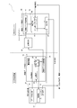
- FIG. 1 is a block diagram of an image inspection system according to an embodiment of the present invention.
- an image inspection system 1 includes a filling and packaging machine 10 that produces a filling and packaging body to be inspected, and a packaging body from image data of the packaging body that is produced by the filling and packaging machine 10.
- the storage device 30 for storing the image data transmitted from the filling and packaging system 10 and the image data of the defective product stored in the storage device 30
- an image data analysis system 40 for analyzing the cause.
- the filling and packaging machine 10, the image data determination system 20, the storage device 30, and the image data analysis system 40 are connected via communication means such as a LAN or the Internet.
- the filling and packaging machine 10 can be various types such as a horizontal filling and packaging machine and another row filling and packaging machine in addition to the vertical filling and packaging machine described in Patent Documents 1 and 2.
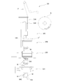
- the vertical filling and packaging machine shown in FIG. 2 will be described as a representative example.
- the filling and packaging machine 10 guides with a guide rod 100 during the running of a single long packaging film F that is continuously fed from the film roll R and running from the top to the bottom.
- the vertical seal mechanism 101 composed of a pair of vertical seal rolls is continuously pressed and heated in the longitudinal direction (vertical direction) of the packaging film F to form the vertical seal portion 102, thereby forming the packaging film F Is formed into a cylindrical shape.
- the article to be packaged M supplied from a tank (not shown) via a pump (not shown) and a supply path is formed into a cylindrical shape by the filling nozzle 103 penetrating from the top to the bottom between the pair of vertical seal rolls.
- a pair of horizontal seals are filled in the packaging film F ′ continuously or intermittently by a predetermined amount, and the packaging film F ′ formed in a cylindrical shape is spaced apart in the longitudinal direction.
- the first horizontal sealing mechanism 104 made of a roll is heated and pressurized over the entire width to be welded together to form the horizontal sealing portion 105 intermittently. Thereafter, the horizontal seal portion 105 is pressed again by the second horizontal seal mechanism 106 to secure the seal, thereby continuously producing a large number of packaging bodies W in the longitudinal direction of the packaging film F. Configured to be bagged.
- the package W may be cut into one bag or a plurality of bags by providing a cutting mechanism 107 on the downstream side of the second horizontal sealing mechanism 106 as shown in the figure.
- the image data determination system 20 is configured by a computer including a CPU, a memory, and the like, and includes an imaging device 21 for imaging a predetermined inspection site of the package W manufactured in the filling and packaging machine 10, and the imaging device 21. It has a determination unit 22 that determines the quality of the package W reflected in the image data by comparing the captured image data with the determination condition that is a criterion for determining the quality of the package stored in the storage unit 23. is doing.
- the imaging device 21 is a device that images the package W continuously manufactured in the filling and packaging machine 10, and for example, a CCD camera, an infrared camera, a CMOS camera, or the like can be used.
- the imaging device 21 is not particularly limited as long as it can detect wrinkles, wrinkles, foaming, etc. of about several ⁇ m generated on the vertical seal portion 102 and the horizontal seal portion 105.
- the imaging device 21 may be provided at any position of the filling and packaging machine 10 as long as it can image a predetermined inspection site of the package W, and a plurality of imaging devices 21 may be provided to image a plurality of inspection sites. It may be. Since the package W is liable to leak due to poor sealing between the vertical seal portion 102 and the horizontal seal portion 105 (wrinkles and continuous foaming), at least the positions of the seal portions 102 and 105, particularly the vertical seal portion. It is preferable that a position where 102 and the lateral seal portion 105 intersect is set as an inspection site.
- the attachment position and appearance of the dispensing nozzle are set at the inspection site, and the casting It is preferable to be able to inspect the displacement of the attachment position of the discharge nozzle, the bending of the tip of the discharge nozzle, and the like.
- the determination unit 22 considers the production conditions acquired from the filling and packaging machine 10 (data output unit 15) for the image data acquired by the imaging device 21, and the determination conditions registered in the storage unit 23 of the image data determination system 20 And the function of determining the quality of the package W reflected in the image data.
- the determination condition is not particularly limited, and for example, reference image data or reference feature data can be used.
- the reference image data is composed of a reference image of a good product and / or a reference image of a defective product.
- a reference image of a non-defective product there is no defect portion at all, and there is a defect portion but not a problem causing a defect. Is also included.
- a reference image of a defective product is one that has a high possibility of occurrence of a defect such as liquid leakage when a defect having the same pattern as the generation pattern of defects such as wrinkles and foams present in the image is generated. It is.
- the comparison with the reference image of the non-defective product and the comparison with the reference image of the defective product may be performed in two stages. For example, after the determination based on the reference image of the non-defective product, the package determined as “defective” The determination accuracy of W can be improved by further determining the reference image of the defective product.
- the reference feature data is obtained by extracting, for each feature, defect portions such as wrinkles and foaming that have caused the occurrence of defects such as liquid leakage from image data captured in the past.
- References for generating defects are stored in the storage unit 23 in advance for each item such as the number, thickness, length, and position of wrinkles, and the number, size, and position of foaming.
- feature data (such as the type, number, and position of defects) is extracted from the image data captured by the imaging device 21, and the feature data is compared with reference feature data stored in the storage unit 23. By doing so, the quality of the package W reflected in the image data is determined.
- the determination unit 22 when the determination result is “defective product”, an exclusion signal is output from the determination unit 22 to the control unit 12 of the filling and packaging machine 10, and the corresponding packaging body W is sent to the filling and packaging machine 10. If it is made to discharge from the provided discharge part 13 to another line, there is no possibility that the packaging body W suspected of being defective will be shipped. In addition, it is preferable to print a barcode, QR code (registered trademark) or the like on the packaging film F in advance on the packaging body W, and the image data and the defective packaging body W are collated with the barcode or the like. If possible, the package W can be accurately discharged from the discharge unit 13.
- QR code registered trademark
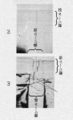
- FIG. 3 shows an example of image data (a) determined as “defective” and image data (b) determined as “non-defective” by the determination unit 22.
- This image data is an image of the position where the vertical seal portion 102 and the horizontal seal portion 105 of the package W intersect, and the image data (a) determined to be “defective” is indicated by an arrow. Wrinkles penetrating in the length direction of the lateral seal portion 105 are generated at the position.
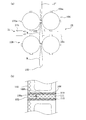
- FIG. 4A An enlarged side view of the first horizontal seal roll 104 portion of the filling and packaging machine 10 of FIG. 2 is shown in FIG.
- the infrared camera 21a is opposed to the packaging film F on the downstream side in the running direction of the packaging film F of the first horizontal seal roll 104 with the packaging film F interposed therebetween.
- An imaging device 21 including an infrared irradiation device 21b is provided at a position where the infrared rays are irradiated.
- the infrared camera 21a it is preferable to use a camera equipped with a CCD sensor, a CMOS sensor or the like and having sensitivity to near infrared rays having a wavelength of 700 to 1700 nm emitted from an infrared irradiation device 21b made of an infrared LED or the like.
- a visible light camera visible light is reflected on the surface of the packaging film F and the inside of the horizontal seal portion 105 cannot be imaged.
- the film F passes through the film F and is reflected at the non-seal positions such as foaming and wrinkles generated in the lateral seal portion 105, so that the line is lifted and a defect image can be clearly picked up.
- the imaging device 21 including the infrared camera 21a and the infrared irradiation device 21b has a horizontal seal portion 105 that is intermittently formed by the first horizontal seal roll 104 as shown in FIG. 104, in particular, a packaging film F from a transverse heat sealing position by the first transverse seal roll 104 (position where the heat seal bars 104a provided at equal intervals in the circumferential direction of the pair of first transverse seal rolls 104 abut). It is preferable to provide so that an image is taken at a position where the length L is within 30 cm, preferably within a position within 20 cm.
- the horizontal seal portion 105 when the horizontal seal portion 105 is imaged immediately after the first horizontal seal roll 104, particularly at a position within 30 cm from the first horizontal seal roll 104, the horizontal seal portion 105 is heated to a high temperature by heating by the first horizontal seal roll 104. Since it is in the state, it is possible to take an image of the foaming generated in the horizontal seal portion 105 in the foamed state. For this reason, a state in which a large number of foams are connected in the horizontal seal portion 105 or a state in which the foams are connected to wrinkles can be detected from the captured image. Can be determined.
- the imaging position is a position more than 30 cm away from the first horizontal seal roll 104 on the downstream side in the running direction of the packaging film F
- foaming generated in the horizontal seal portion 105 is cooled by the horizontal seal portion 105.
- small foam of about several ⁇ m disappears completely, so even a poorly sealed part that causes a slow leak cannot be detected from the captured image, and the slow leak is not detected. There is a possibility that it cannot be detected immediately after the package W is manufactured.
- the vertical seal portion 102 is heated and remelted together with the horizontal seal portion 105, and wrinkles may occur at that time. Also in this case, if the infrared camera 21a captures a position within 30 cm from the lateral heat seal position, the foam generated in the lateral seal portion 105 can be imaged in the foamed state. It is possible to determine whether or not the wrinkles generated at the intersecting position of the seal portion 105 and the vertical seal portion 102 communicate with each other and become a defective seal portion.
- An image (video signal) picked up by the image pickup device 21 is obtained by using characteristic data (for example, wrinkles) such as a combination of wrinkles and bubbles in the horizontal seal portion 105, a combination of wrinkles and bubbles, using an image processing device including a computer.
- characteristic data for example, wrinkles
- the determination unit 22 extracts the feature data and the reference feature data accumulated in the storage unit 23 (for example, reference image data, or a past occurrence). Comparison is made with the data of the defect for each type and feature).
- the determination unit 22 extracts and compares the feature data with the reference feature data stored in the storage unit 23, thereby determining a slow leak that causes liquid leakage after a lapse of time from the manufacture of the package W. It can be carried out immediately after the production of the package W.
- the horizontal seal portion 105 has sufficient seal strength if the seal edge 108 on the filling space side is continuously formed in a strip shape with a length of 3.0 mm and at least 1.0 mm in the vertical seal direction. In other words, if there is a finely sealed portion such as fine foam or wrinkles in this determination region 110, peeling of the lateral seal portion 105 from several hours to several days starts from that portion. This is because liquid leakage (slow leak) occurs from the cut end face when the horizontal seal portion 105 is cut at the cutting position 111 (the central position in the length direction of the horizontal seal portion 105).
- the non-seal portion 109a is composed of a series of bubbles, but because it is located outside the determination region 110, it is determined that there is no possibility of causing a slow leak, Since the non-seal portion 109b is located at the seal edge 108 portion in the determination region 110, it is determined that there is a possibility of causing a slow leak.
- the packaging film F has printing of colors, patterns, characters, etc.
- the aperture value of the infrared camera 21a is adjusted to the printed part, the part without printing becomes too bright and there is no printing. If the aperture value of the infrared camera 21a is adjusted to a portion, the printed portion may become too dark, and none of the horizontal seal portion 105 may be projected. Therefore, a plurality of infrared cameras 21a having different exposures are provided, and the definition and / or the exposure are obtained from a plurality of captured images captured by each camera 21a or a captured image captured by the infrared camera 21a.
- the image processing apparatus uses one captured image (a) captured by the infrared camera 21 a.
- the image processing apparatus uses one captured image (a) captured by the infrared camera 21 a.
- the image processing apparatus uses one captured image (b) captured by the infrared camera 21 a.
- the image processing apparatus uses one captured image (b) captured by the infrared camera 21 a.
- the image processing apparatus uses one captured image (b) captured by the infrared camera 21 a.
- the region B is cut out, and the combined region A and region B are combined to form a composite image (d).
- the entire horizontal seal portion 105 can be clearly projected as one image without being obstructed by the printing layer of the packaging film F, the same method as the packaging film F without the printing layer can be used. Slow leak can be
- the image data determined by the determination unit 22 as described above is transmitted from the image data transmission unit 24 to the storage device 30 and stored together with the determination result and the production conditions of the filling and packaging machine 10.
- the feature data extracted from the image data is stored from the image data transmission unit 24 together with the image data or instead of the image data at the determination by the determination unit 22. You may transmit to the apparatus 30.
- the image data and the feature data extracted from the image data are collectively referred to as “image data or the like”.
- the image data transmission unit 24 associates the image data captured by the imaging device 21 with the current production condition information of the filling and packaging machine 10 and the determination result of the determination unit 22, and stores the data via the Internet as a communication unit. 30. Since the package W is produced in large quantities at a speed of, for example, about 100,000 pieces / day, it may be set so as to be transmitted every few minutes or every several hours.
- the storage device 30 has a function of accumulating image data and the like acquired by the image data determination system 20 and production conditions and determination result information associated with the image data and the like.
- the storage device 30 is associated with, for example, a pattern of a defective portion and a production condition (for example, the type of plastic film, the type of package, the filling amount, the pitch, etc.) It is preferable to store it in a plurality of directories and folders.
- image data and the like stored in the storage device 30 are used as storage information data when analyzing the cause of the occurrence of defective products in the calculation unit 42 described later, the image data and the like are stored in the storage device 30. Is preferably finely classified and patterned on the basis of the defect form and production conditions, etc. According to this, the relationship between the defect form and the production conditions becomes clear, and the analysis work by the calculation unit 42 described later is performed. It can be performed quickly and with high accuracy.
- the image data analysis system 40 examines the cause of the occurrence of the defect and countermeasures.
- the image data analysis system 40 is configured by a computer including a CPU, a memory, and the like, and includes an image data acquisition unit 41 and a calculation unit 42, and the image data acquisition unit 41 is newly registered in the storage device 30. And the like, the determination unit 22 has a function of acquiring image data determined to be “defective”. On the other hand, image data determined to be “good” can be used for production management of the package as traceability (production history).
- the calculation unit 42 causes the occurrence of the defect by comparing the image data of the “defective product” acquired from the image data acquisition unit 41 with the stored information data (past image data and feature data) stored in the storage device 30. It has the analysis part 43 which analyzes. Specifically, for example, the analysis unit 43 matches image data or the like determined as defective with past information (image data, feature data, production conditions, etc.) accumulated in large quantities in the storage device 30. specify a reason. The analysis unit 43 also determines new production conditions for the filling and packaging machine 10 (for example, the tension of the packaging film F, the temperature and speed of the vertical seal mechanism 101, the first horizontal seal, etc.) for eliminating the occurrence of defects from the analysis result. The temperature and speed of the mechanism 104, the upper and lower of the production speed, etc.) can be calculated based on past image data and the like, production conditions associated therewith, and the like.
- the new production conditions calculated by the analysis unit 43 are input to the control unit 12 of the filling and packaging machine 10 via the transmission unit 45, and the production conditions of the filling and packaging machine 10 (for example, the strength of the tension of the packaging film F)
- the production conditions of the filling and packaging machine 10 for example, the strength of the tension of the packaging film F
- the change of the temperature and speed of the vertical seal mechanism 101, the change of the temperature and speed of the first horizontal seal mechanism 104, the upper and lower of the production speed, etc.) are automatically changed. Therefore, the time from the operation stop to the operation restart due to the occurrence of the failure can be shortened, or the failure can be solved without stopping the operation.
- the packaging body W (pseudo-defective product), which is determined as a defective product by the determination unit 22 and removed from the production line via the discharge unit 13, a defect such as liquid leakage occurs when stored and observed for several days. Confirm.
- the result is input to the determination condition correction unit 44. If liquid leakage does not occur even though the determination unit 22 determines that the product is defective, the determination condition correction unit 44 instructs to change reference image data or reference feature data as a determination condition (error). An instruction for deleting or correcting the image or feature data that is the basis of the determination is output to the transmission unit 45.
- the transmission unit 45 transmits the instruction to the storage unit 23 of the image data determination system 20 via the Internet as a communication unit, and the accumulated reference image data and reference feature data are changed (an image that has become a reference for erroneous determination). Or feature data is deleted or modified). Note that this process is repeated each time an erroneous determination occurs in the determination unit 22, so that the determination accuracy by the determination unit 22 can be improved, and the frequency of picking as a defective product can be reduced despite the non-defective product.
- the determination unit 22 extracts the image data and the like from the image data.
- a classification unit 25 is provided for classifying into predetermined categories based on information (for example, the position, size, number of wrinkles and bubbles).
- the image data transmitting unit 24 associates the classification conditions of each category, the number of image data belonging to each category, the current production conditions of the filling and packaging machine 10, the determination result by the determination unit 22, and the like so as to transmit them to the storage device 30. It is configured. With this configuration, the amount of information can be significantly reduced as compared with the case where image data captured by the imaging device 21 is transmitted to the storage device 30 as it is, so that the communication load can be reduced and closer to real time. Transmission is possible.
Landscapes
- Engineering & Computer Science (AREA)
- Mechanical Engineering (AREA)
- Physics & Mathematics (AREA)
- General Physics & Mathematics (AREA)
- Health & Medical Sciences (AREA)
- Immunology (AREA)
- Pathology (AREA)
- Life Sciences & Earth Sciences (AREA)
- Chemical & Material Sciences (AREA)
- Analytical Chemistry (AREA)
- Biochemistry (AREA)
- General Health & Medical Sciences (AREA)
- Computer Vision & Pattern Recognition (AREA)
- Quality & Reliability (AREA)
- Theoretical Computer Science (AREA)
- Toxicology (AREA)
- Thermal Sciences (AREA)
- Signal Processing (AREA)
- Containers And Plastic Fillers For Packaging (AREA)
- Investigating Materials By The Use Of Optical Means Adapted For Particular Applications (AREA)
Abstract
製造した包装体の良否を自動で判別することができると共に、充填包装機の生産条件の変更を自動で行うことのできる包装体の画像検査システムであって、充填包装機と、画像データ判定システムと、記憶装置と、画像データ解析システムとを備え、前記画像データ判定システムが、包装体を撮像する撮像装置と、包装体の良否の判定条件を記憶する記憶部と、包装体の良否を判定する判定部と、撮像装置で撮像した画像データ等を記憶装置へ送信する画像データ送信部とを備え、前記画像データ解析システムが、記憶装置から判定部で不良と判定された画像データ等を取得する画像データ取得部と、画像データ取得部で取得した画像データから充填包装機の生産条件を解析する解析部と前記判定部における判定条件を修正する判定条件修正部とからなる演算部と、新たな生産条件を充填包装機に送信すると共に、新たな前記判定条件を前記記憶部に送信する送信部とを備える。
Description
本発明は、飲食物や調味料、化粧品、医薬品等の液状や粘稠状の被包装物をプラスチックフィルムからなる包装袋内に充填包装した包装体の画像検査システムに関する。
プラスチックフィルムからなる包装袋内に液状や粘稠状の被包装物を自動的に充填包装する充填包装機については、特許文献1および特許文献2に記載されているような自動充填機が知られている。
この自動充填機は、例えばベースフィルム層とシーラント層とを具える積層フィルムからなる長尺の包装用フィルムを、その長手方向に上方から下方へ連続的に走行させながら、前記シーラント層が向い合わせになるように幅方向に半折りし、その重なり合うフィルム両側縁どうしを縦方向に連続的にヒートシールして、縦シール部を形成して該フィルムを筒状とし、次いで該筒状の包装用フィルムの底部側となる箇所に、該包装用フィルムの幅方向に沿って横方向へヒートシールして横シール部を形成し、該筒状の包装用フィルム内に被包装物を充填しつつ、該被包装物を押し出しながら袋口側となる箇所に横シール部を形成することで連続的に包装体が製造されるように構成されている。
この自動充填機は、各種のスイッチやタッチパネルを具える操作パネルを有し、該操作パネルにおいて、包装形態に応じた生産条件(包装用フィルムの移送速度の設定、シールピッチの設定、被包装物の充填量の設定や動作タイミングの設定、縦シール機構、横シール機構のシール圧の設定や動作タイミングの設定などの生産条件等)を項目毎に数値にて入力することで設定できるように構成されている。
しかしながら、上記自動充填機の設定には、経験に基づいた細かい調整が必要とされるため、ユーザー自らが設定を行うことはせず、例えば、シール部の不具合等のトラブルが発生すると、自動充填機のメーカーの作業員がユーザーの元へ出向いて自動充填機の設定変更(調整)を行っていた。このため、運転を再開するまでに時間がかかるという問題点があった。
また、生産条件(設定)が適正でないと、縦シール部や横シール部にシワや発泡が発生することがある。このようなシワや発泡は、数μm程度の小さいものであっても、該発泡が繋がることや、発泡やシワが複数組み合わさること等によって、貫通孔や時間経過後に貫通孔となるような擬似貫通孔を形成し、該貫通孔や擬似貫通孔を通って被包装物が1~数日後に洩れ出し始める所謂スローリーク(遅れ洩れ)を発生するおそれがある。このような数μmの発泡やシワ等は、目視による確認が難しいため、従来、製造した包装体を3日間程度一時的に保管しておき、実際の液洩れの有無で包装体の良否を判定していた。
しかし、この方法では、大量の包装体を保管する場所を確保する必要がある点、製造後すぐに出荷できない点、液洩れが発生した場合に周囲の包装体を汚損する点など、多くの問題点があった。しかも、包装体は、横シール部を介して複数個、繋げた状態(連包状態)で出荷することが多く、この場合には、たとえ包装体間の横シール部内にシール不良部分が存在していても、出荷先において単包ずつに切断するまで液洩れが生じることがないため、出荷前に該シール不良部分を検知し、スローリークの可能性を判定することができなかった。
なお、包装体からのスローリークは、その大半が横シール部および横シール部と縦シール部とが交差する位置から発生している。この原因としては、第1に上記のように長尺の包装用フィルムを幅方向に折り返して側縁どうしを縦シールして筒状とした後、該筒状の包装用フィルム内に被包装物を充填すると、被包装物の重量によって包装用フィルムが変形して縦シワが生じ易く、とくに特許文献3のように、包装体の長尺となる側部シール部側を横シール部とした場合には、前記縦シワの発生が顕著となり、この状態で横シールを施すことにより、横シール部および横シール部と縦シール部とが交差する位置にシール部を貫通する貫通シワが発生し、該貫通シワを介して液洩れが発生することが挙げられる。
また、第2の原因としては、横シール部が、一対の横シールロールによって液状の被包装物を押し出しながらヒートシールする液中シール充填により形成されることが挙げられる。この液中シール充填は、被包装物の温度や種類等によってヒートシールにバラツキが生じやすくヒートシール不良が生じやすい。
さらに、横シール部内には、必然的に被包装物が介在することになるし、そこに一部が滞留し残留して噛み込まれやすい。とくに、被包装物が液状物と共に窒素等のガスを充填した気液混相流体である場合、横シール部内へのガスの噛み込みの可能性が高くなり、また、横シール部内に噛み込まれた液状物が、横シールロールによる圧力から解放されると同時に膨張(200~600倍)して発泡することがあり、前記気泡や発泡が、横シール部を貫通するものであったり、複数の発泡が横シール部を貫通するように連続して形成されたりすると、シール不良となって直ちに液洩れにつながり、該気泡の状態態やシワとの関係によってはスローリークを発生させる可能性もある。
さらに、横シール部内には、必然的に被包装物が介在することになるし、そこに一部が滞留し残留して噛み込まれやすい。とくに、被包装物が液状物と共に窒素等のガスを充填した気液混相流体である場合、横シール部内へのガスの噛み込みの可能性が高くなり、また、横シール部内に噛み込まれた液状物が、横シールロールによる圧力から解放されると同時に膨張(200~600倍)して発泡することがあり、前記気泡や発泡が、横シール部を貫通するものであったり、複数の発泡が横シール部を貫通するように連続して形成されたりすると、シール不良となって直ちに液洩れにつながり、該気泡の状態態やシワとの関係によってはスローリークを発生させる可能性もある。
しかも、横シール部内に発生した発泡は、横シールロール直後の、横シール部が高温の状態にある間はそのまま発泡状態にあるものの、下流側に移動する間に冷却されると、収縮して消滅するため、たとえ直ちに液洩れにつながるような大きな発泡があったとしても、これを発見できない場合がある。
本発明は、上記問題を解消し、製造した包装体の良否を自動で判別することができると共に、充填包装機の生産条件の変更を自動で行うことのできる包装体の画像検査システムを提供することを目的とする。
上記目的を解決するため鋭意検討した結果、発明者らは、以下に述べる要旨構成に係る本発明に想到した。
即ち、本発明は、プラスチックフィルムからなる包装体の画像検査システムであって、
充填包装機と、画像データ判定システムと、記憶装置と、画像データ解析システムとを備え、
前記画像データ判定システムは;
前記充填包装機で製造された包装体を撮像する撮像装置、
前記包装体の良否の判定条件を記憶する記憶部、
前記撮像装置で撮像した包装体の画像データから、該包装体の良否を判定する判定部と、
前記画像データおよび/またはその画像データに関連する情報を、前記判定部の判定結果および前記充填包装機の生産条件と共に、前記記憶装置へ通信手段を介して送信する画像データ送信部、からなり、
前記画像データ解析システムは;
前記記憶装置から前記判定部により不良と判定された前記画像データおよび/またはその画像データに関連する情報を取得する画像データ取得部、
前記画像データ取得部で取得した前記画像データおよび/またはその画像データに関連する情報から、その不良原因およびその不良を解決するための新たな生産条件を、前記記憶装置に蓄積された過去の画像データまたはその画像データに関連する情報と、これに関連付けられている前記充填包装機の生産条件に基づいて解析する解析部、および前記判定部において不良品と判定された包装体の保管および観察の結果から、該判定部の判定が不正確と判断された場合に、前記判定条件を修正する判定条件修正部からなる演算部、
通信手段を介して、前記解析部で得られた前記新たな生産条件を前記充填包装機に送信すると共に、前記判定条件修正部で得られた新たな判定条件を前記記憶部に送信する送信部、からなることを特徴とする。
なお、本発明においては、前記判定部は、前記画像データおよび/またはその画像データに関連する情報を所定のカテゴリ別に分類する分類部を有し、前記画像データ送信部は、前記各カテゴリに属する画像データおよび/またはその画像データに関連する情報の数と、前記充填包装機の現状の生産条件および前記判定部の前記判定結果とを関連付けて前記記憶装置へ送信するよう構成されていることがより好ましい解決手段となる。
本発明の包装体の画像検査システムによれば、製造した包装体の良否が自動で判別されると共に、充填包装機の生産条件が自動で変更されるので、不具合の発生に伴う操業停止から操業再開までの時間を短くすることができる。
また、本発明の画像検査システムによれば、製造される包装体の良否を、画像データを用いて判定するため、目視では確認できないような小さな欠陥も検出することができる。とくに、従来の目視による選別では確認することができなかったヒートシール部上に発生する数μm程度の小さなシワや発泡をも検出することができるため、包装体の製造直後において該シワ等がスローリークの原因となるものか否かを判定することができ、スローリークの検知に要する時間(待機時間)の必要のない、オンラインでの検知を行うことができることから、液洩れ検査に要する時間、場所およびコストを削減することができる。
さらに本発明の画像検査システムによれば、包装体の良否判定に使用する判定条件として、過去の画像データや該画像データから抽出した特徴データを、欠陥箇所及び大きさ等とその生産条件(包装体の品種やピッチ、充填包装機の運転条件等)に応じてパターン化したものを利用することができる。なお、判定条件は、画像データや特徴データに限定されるものではない。
以下、本発明にかかる画像検査システムを、図面を参照して説明する。
図1は、本発明の一実施形態にかかる画像検査システムのブロック図である。
図1に示すように、本実施形態にかかる画像検査システム1は、検査対象となる充填包装体を製造する充填包装機10と、充填包装機10によって製造される包装体の画像データから包装体の良否を判定する画像データ判定システム20と、該充填包装システム10から送信された画像データ等を蓄積する記憶装置30と、該記憶装置30に蓄積された不良品の画像データ等から、その不良原因を解析する画像データ解析システム40とを備えている。前記充填包装機10、前記画像データ判定システム20、前記記憶装置30および画像データ解析システム40は、LANやインターネット等の通信手段を介して接続されている。
充填包装機10は、特許文献1、2に記載のような縦型充填包装機の他、横型充填包装機や他列充填包装機等の各種のものとすることができる。以下は、図2に示す縦型充填包装機を代表例として説明する。充填包装機10は、フィルムロールRから連続的に繰り出されて走行する1枚の長尺の包装用フィルムFを上方から下方へ連続的に走行させながら、その走行中にガイドロッド100で案内しつつ包装用フィルムFをそのシーラント層が互いに向い合せになるように幅方向に折り返し、図では包装用フィルムFの左端部に位置するその両側端部同士を重ね合わせ、その重ね合わされた両側端部同士を1対の縦シールロールからなる縦シール機構101によって包装用フィルムFの長手方向(縦方向)に連続的に加圧および加熱して縦シール部102を形成し、これにより包装用フィルムFを筒状に形成する。次いで、図示しないタンクから図示しないポンプおよび供給路を介して供給された被包装物Mを、上記1対の縦シールロール間を上方から下方へ貫通している充填ノズル103によって、筒状に形成した包装用フィルムF'の内側へ連続的に、または所定量ずつ間欠的に充填すると共に、筒状に形成した包装用フィルムF’をその長手方向に一定間隔をおいて、1対の横シールロールからなる第1横シール機構104によって全幅にわたり加熱しつつ加圧して互いに溶着させて間欠的に横シール部105を形成する。その後、第2横シール機構106で横シール部105を再押圧して該シールを確実なものとし、これにより多数の包装体Wが包装用フィルムFの長手方向へつながった状態で連続的に製袋されるように構成される。なお、包装体Wは、図に示すように第2横シール機構106の下流側に切断機構107を設けて一袋ずつもしくは複数袋ずつに切断してもよい。
画像データ判定システム20は、CPUおよびメモリ等を備えるコンピュータによって構成され、上記充填包装機10において製造される包装体Wの所定の検査部位を撮像するための撮像装置21と、該撮像装置21によって撮像された画像データを、記憶部23に蓄積された包装体の良否の判定の基準となる判定条件と比較することで、該画像データに映る包装体Wの良否を判断する判定部22を有している。
撮像装置21は、充填包装機10において連続して製造される包装体Wを撮像する装置であり、例えば、CCDカメラや赤外線カメラ、CMOSカメラ等を用いることができる。撮像装置21は、縦シール部102および横シール部105上に発生する数μm程度のシワや疵、発泡等を検出できるものであれば特に限定されない。
撮像装置21は、包装体Wの所定の検査部位を撮像することができれば、充填包装機10のどの位置に設けてもよく、また複数の撮像装置21を設けて複数の検査部位を撮像できるようにしてもよい。
なお、包装体Wは、縦シール部102と横シール部105のシール不良(シワや連続発泡の発生)によって液洩れが発生しやすいことから、少なくとも該シール部102、105位置、とくに縦シール部102と横シール部105とが交差する位置を検査部位とすることが好ましい。また、包装体Wが、特開2005-59958号公報に記載のようなフィルム状の注出ノズルを具える場合には、該注出ノズルの取り付け位置や外観を検査部位に設定し、該注出ノズルの取付け位置のずれや、注出ノズル先端の折れ曲がり等が検査できるようにすることが好ましい。
なお、包装体Wは、縦シール部102と横シール部105のシール不良(シワや連続発泡の発生)によって液洩れが発生しやすいことから、少なくとも該シール部102、105位置、とくに縦シール部102と横シール部105とが交差する位置を検査部位とすることが好ましい。また、包装体Wが、特開2005-59958号公報に記載のようなフィルム状の注出ノズルを具える場合には、該注出ノズルの取り付け位置や外観を検査部位に設定し、該注出ノズルの取付け位置のずれや、注出ノズル先端の折れ曲がり等が検査できるようにすることが好ましい。
判定部22は、撮像装置21で取得した画像データを、充填包装機10(データ出力部15)から取得した生産条件を考慮し、画像データ判定システム20の記憶部23に登録されている判定条件と比較することにより該画像データに映る包装体Wの良否を判定する機能を有する。
判定条件としては、特に限定されるものではないが、例えば基準画像データや基準特徴データを用いることができる。
基準画像データは、良品の基準画像および/または不良品の基準画像からなり、良品の基準画像としては、欠陥箇所が全く存在しないものの他、欠陥箇所が存在するが不具合を発生する程度ではないものも含まれる。一方、不良品の基準画像とは、該画像内に存在するシワや発泡等の欠陥の発生パターンと同様のパターンの欠陥が発生した場合に、液洩れ等の不具合が発生する可能性が高いものである。
なお、良品の基準画像との比較と不良品の基準画像との比較を2段階で行ってもよく、例えば、良品の基準画像による判定を行った後、「不良品」と判定された包装体Wについて、さらに不良品の基準画像との判定を行うことにより、判定精度を向上させることができる。
なお、良品の基準画像との比較と不良品の基準画像との比較を2段階で行ってもよく、例えば、良品の基準画像による判定を行った後、「不良品」と判定された包装体Wについて、さらに不良品の基準画像との判定を行うことにより、判定精度を向上させることができる。
また、基準特徴データは、過去に撮像された画像データから、液洩れ等の不具合の発生要因となったシワや発泡等の欠陥箇所を特徴毎に抽出してデータ化してものであり、例えば、シワの数や太さ、長さ、位置、および発泡の数や大きさ、位置などの各項目についてそれぞれ不具合の発生する基準を予めデータ化して記憶部23に蓄積しておく。
判定部22における判定に際しては、撮像装置21で撮像した画像データから特徴データ(欠陥の種類や数、位置など)を抽出し、該特徴データを、記憶部23に蓄積された基準特徴データと比較することで、画像データに映る包装体Wの良否を判定する。
判定部22における判定に際しては、撮像装置21で撮像した画像データから特徴データ(欠陥の種類や数、位置など)を抽出し、該特徴データを、記憶部23に蓄積された基準特徴データと比較することで、画像データに映る包装体Wの良否を判定する。
判定部22において、判定結果が「不良品」となった場合には、判定部22から充填包装機10の制御部12へ排除信号を出力し、該当する包装体Wを、充填包装機10に設けた排出部13から別ラインへと排出されるようにすれば、不良品の疑いのある包装体Wが出荷されるおそれがない。なお、包装体Wには、包装用フィルムFに予めバーコードやQRコード(登録商標)等を印刷しておくことが好ましく、該バーコード等によって画像データと不良品の包装体Wとを照合できるようにしておけば、該包装体Wを正確に排出部13から排出することができる。
図3に、判定部22において、「不良品」と判定された画像データ(a)と「良品」と判定された画像データ(b)の一例を示す。この画像データは、包装体Wの縦シール部102と横シール部105とが交差する位置を撮像したものであり、「不良品」と判定された画像データ(a)には、矢印で示した位置に横シール部105の長さ方向に貫通するシワが発生している。
ここで、判定部22において横シール部105のシール不良を判定する方法を一例として説明する。
図2の充填包装機10の、第1横シールロール104部分の拡大側面図を図4(a)に示す。図4(a)に示したように、第1横シールロール104の包装用フィルムFの走行方向下流側に、包装体Wに対面するように赤外線カメラ21aと、包装用フィルムFを挟んで対向する位置に赤外線照射装置21bと、からなる撮像装置21が設けられている。赤外線カメラ21aとしては、CCDセンサ、CMOSセンサ等が搭載され、赤外線LED等からなる赤外線照射装置21bから照射された波長が700~1700nmの近赤外線に対する感度を有するものを用いることが好ましい。これは、可視光カメラで包装用フィルムFを撮像すると、可視光線は、包装用フィルムFの表面で反射し、横シール部105内を撮像することができないのに対し、近赤外線は、包装用フィルムFを透過して横シール部105内に発生した発泡やシワ等の非シール位置で反射するため、ラインが浮かび上がり、欠陥像を鮮明に撮像することができるためである。
図2の充填包装機10の、第1横シールロール104部分の拡大側面図を図4(a)に示す。図4(a)に示したように、第1横シールロール104の包装用フィルムFの走行方向下流側に、包装体Wに対面するように赤外線カメラ21aと、包装用フィルムFを挟んで対向する位置に赤外線照射装置21bと、からなる撮像装置21が設けられている。赤外線カメラ21aとしては、CCDセンサ、CMOSセンサ等が搭載され、赤外線LED等からなる赤外線照射装置21bから照射された波長が700~1700nmの近赤外線に対する感度を有するものを用いることが好ましい。これは、可視光カメラで包装用フィルムFを撮像すると、可視光線は、包装用フィルムFの表面で反射し、横シール部105内を撮像することができないのに対し、近赤外線は、包装用フィルムFを透過して横シール部105内に発生した発泡やシワ等の非シール位置で反射するため、ラインが浮かび上がり、欠陥像を鮮明に撮像することができるためである。
なお、赤外線カメラ21aと赤外線照射装置21bからなる撮像装置21は、図4(a)に示すように第1横シールロール104によって間欠的に形成される横シール部105を、第1横シールロール104、とくには、第1横シールロール104による横ヒートシール位置(一対の第1横シールロール104の周方向に等間隔に設けられたヒートシールバー104a同士が当接する位置)から包装用フィルムFの走行方向に長さLが30cm以内の位置、好ましくは20cm以内の位置で撮像するように設けることが好ましい。
このように、横シール部105を、第1横シールロール104の直後、とくに第1横シールロール104から30cm以内の位置で撮像すると、横シール部105は第1横シールロール104による加熱によって高温状態にあるため、横シール部105内に発生した発泡を、その発泡状態のままで撮像することができる。そのため、横シール部105内の、発泡が多数繋がった状態や発泡とシワとが連通した状態等を、撮像画像から検出することができるため、それらがスローリークをもたらすシール不良部分となるか否かの判定を行うことができる。なお、撮像位置が第1横シールロール104から包装用フィルムFの走行方向下流側に30cm超離れた位置となった場合、横シール部105内に発生した発泡は、該横シール部105の冷却に伴って収縮し、とくに数μm程度の小さな発泡は完全に消失してしまうため、たとえスローリークを生じるようなシール不良部分であっても撮像画像からは検出することができず、スローリークを包装体Wの製造直後に検知することができないおそれがある。
また、第1横シールロール104による包装用フィルムFの加熱に際しては、横シール部105と共に、縦シール部102が加熱されて再溶融し、その際にシワを発生することがある。この場合にも、赤外線カメラ21aによって横ヒートシール位置から30cm以内の位置を撮像すれば、横シール部105内に発生した発泡を発泡状態のままで撮像することができるため、該発泡と、横シール部105と縦シール部102との交差位置に発生したシワとが連通してシール不良部分となるか否かの判定を行うことができる。
撮像装置21で撮像された画像(映像信号)は、コンピュータ等からなる画像処理装置を用いて横シール部105内のシワや気泡の連なり、シワと気泡との組み合わせ等の特徴データ(例えば、シワの長さや位置、気泡の大きさや位置、数等)が抽出され、判定部22において、該特徴データと、記憶部23に蓄積された基準特徴データ(例えば、基準画像データや、過去に発生した欠陥を種類や特徴ごとにデータ化したもの)との比較が行われる。
とくに、図4(b)に示すように、前記撮像画像に写る横シール部105の、被包装物の充填スペース側のシールエッジ108から縦シール方向に3.0mm以内の領域110(図4(b)に一点鎖線で示す領域、以下「判定領域110」と言う。)にある貫通孔(充填スペースに繋がっているもの)もしくは擬似貫通孔(時間経過後に充填スペースに繋がるもの)から特徴データを抽出し、判定部22において、該特徴データと、記憶部23に蓄積された基準特徴データとの比較を行うことで、包装体Wの製造から時間経過後に液洩れを生じさせるスローリークの判定を、包装体Wの製造直後に行うことができる。
これは、横シール部105は、充填スペース側のシールエッジ108が、縦シール方向に3.0mm、少なくとも1.0mmの長さで帯状に連続して形成されていれば、十分なシール強度を付与することができるためであり、つまり、この判定領域110に微細な発泡やシワ等のシール不良部分が存在すると、該部分が起点となって横シール部105の剥離が数時間~数日をかけて徐々に進み、横シール部105を切断位置111(横シール部105の長さ方向中央位置)で切断した際に切断端面から液洩れ(スローリーク)が発生するためである。
図4(b)の場合では、非シール部分109aは、気泡の連なりからなるが、判定領域110の領域外に位置しているため、スローリークを生じる可能性なしと判定されるのに対し、非シール部分109bは、判定領域110内のシールエッジ108部分に位置しているため、スローリークを生じる可能性有り、と判定されることになる。
ところで、包装用フィルムFが色や柄、文字等の印刷を有する場合、例えば、赤外線カメラ21aの絞り値を印刷部分に合わせると、印刷のない部分が明るくなりすぎてしまい、反対に印刷のない部分に赤外線カメラ21aの絞り値を調整すると、印刷部分が暗くなりすぎて、いずれも横シール部105全体を写し出すことができないことがある。
そのため、露出の異なる複数台の赤外線カメラ21aを設けて、それぞれのカメラ21aで撮像された複数枚の撮像画像、または赤外線カメラ21aで撮像された1枚の撮像画像から鮮明度および/または露出を調整して得た複数枚の画像から、画像処理装置によって最適な部分(横シール部105内部が鮮明に写し出された部分)だけを切り取って合成(再構成)することが好ましい。この方法では、図5に例示するように、領域Aが印刷を有し、領域Bが透明フィルムからなる場合に、赤外線カメラ21aで撮像された1枚の撮像画像(a)から、画像処理装置を用いて領域Aに露出を合わせた画像(b)と、領域Bに露出を合わせた画像(c)をそれぞれ作成し、画像(b)からは領域Aの部分を切り取り、一方、画像(c)からは領域Bの部分を切り取り、切り取った領域Aと領域Bの部分を組み合わせて合成画像(d)を形成する。これによれば、包装用フィルムFの印刷層に邪魔されることなく、横シール部105全体を1枚の画像として鮮明に写し出すことができるため、印刷層のない包装用フィルムFと同じ方法でスローリークの判定を行うことができる。
そのため、露出の異なる複数台の赤外線カメラ21aを設けて、それぞれのカメラ21aで撮像された複数枚の撮像画像、または赤外線カメラ21aで撮像された1枚の撮像画像から鮮明度および/または露出を調整して得た複数枚の画像から、画像処理装置によって最適な部分(横シール部105内部が鮮明に写し出された部分)だけを切り取って合成(再構成)することが好ましい。この方法では、図5に例示するように、領域Aが印刷を有し、領域Bが透明フィルムからなる場合に、赤外線カメラ21aで撮像された1枚の撮像画像(a)から、画像処理装置を用いて領域Aに露出を合わせた画像(b)と、領域Bに露出を合わせた画像(c)をそれぞれ作成し、画像(b)からは領域Aの部分を切り取り、一方、画像(c)からは領域Bの部分を切り取り、切り取った領域Aと領域Bの部分を組み合わせて合成画像(d)を形成する。これによれば、包装用フィルムFの印刷層に邪魔されることなく、横シール部105全体を1枚の画像として鮮明に写し出すことができるため、印刷層のない包装用フィルムFと同じ方法でスローリークの判定を行うことができる。
上記のようにして判定部22において判定された画像データは、該判定結果、および充填包装機10の生産条件と共に、画像データ送信部24から記憶装置30へと送信され、蓄積される。なお、判定条件として基準特徴データを用いた場合には、判定部22における判定の際に、画像データから抽出した特徴データを、画像データと共に、または画像データの代わりに画像データ送信部24から記憶装置30へ送信してもよい。以下は、画像データと該画像データから抽出した特徴データとを合わせて「画像データ等」と言う。
画像データ送信部24は、撮像装置21で撮像した画像データ等を、充填包装機10の現状の生産条件の情報および判定部22の判定結果と関連付けて、通信手段としてのインターネットを介して記憶装置30に送信する機能を有する。包装体Wは、例えば約10万個/日のスピードで大量に生産されるため、数分おきや数時間おきにまとめて送信するように設定してもよい。
記憶装置30は、画像データ判定システム20で取得した画像データ等と、その画像データ等に関連付けられた生産条件や判定結果の情報等を蓄積する機能を有する。この記憶装置30は、送信される大量の画像データ等を保存するため、例えば、欠陥箇所のパターンおよび生産条件(例えば、プラスチックフィルムの品種や被包装物の種類、充填量、ピッチ等)と関連付けて複数のディレクトリやフォルダに分けて保存することが好ましい。
とくに、記憶装置30に蓄積された画像データ等は、後述する演算部42において不良品の発生原因を解析する際の蓄積情報データとして利用されるため、記憶装置30への画像データ等の蓄積に際しては、欠陥の形態および生産条件等に基づいて細かく分類してパターン化することが好ましく、これによれば欠陥の形態と生産条件との関係が明確になり、後述する演算部42による解析作業を迅速に、かつ高い精度で行うことができる。
記憶装置30に蓄積された画像データ等のうち、判定部22において不良品と判定された画像データ等については、画像データ解析システム40において欠陥発生の原因と対策が検討される。
画像データ解析システム40は、CPUやメモリ等を備えるコンピュータによって構成され、画像データ取得部41と演算部42とを備え、該画像データ取得部41は、記憶装置30に新たに登録された画像データ等の中から、判定部22において「不良品」と判断された画像データ等を取得する機能を有している。一方、「良品」と判断された画像データ等については、トレーサビリティ(生産履歴)として包装体の生産管理に利用することができる。
演算部42は、画像データ取得部41から取得した「不良品」の画像データ等と、記憶装置30に蓄積された蓄積情報データ(過去の画像データや特徴データ)との比較によって欠陥発生の原因を解析する解析部43を有する。具体的には、解析部43は例えば、不良品として判定された画像データ等と、記憶装置30に大量に蓄積された過去の情報(画像データ、特徴データ、生産条件等)とをマッチングさせて原因を特定する。また、解析部43は、解析結果から欠陥の発生を解消するための充填包装機10の新たな生産条件(例えば、包装用フィルムFのテンション、縦シール機構101の温度および速度、第1横シール機構104の温度および速度、生産速度の上下等)を、過去の画像データ等とそれに関連づけられた生産条件等に基づき算出することができる。
解析部43で算出された新たな生産条件は、送信部45を介して充填包装機10の制御部12に入力され、該充填包装機10の生産条件(例えば、包装用フィルムFのテンションの強弱、縦シール機構101の温度および速度の変更、第1横シール機構104の温度および速度の変更、生産速度の上下等)が自動で設定変更されることになる。そのため、不具合の発生に伴う操業停止から操業再開までの時間を短縮することができ、あるいは操業を停止させることなく、不具合を解決することができる。
また、判定部22において不良品と判定され、排出部13を介して製造ラインから外された包装体W(擬不良品)については、数日間、保管、観察して液洩れ等の不具合の発生を確認する。その結果は、判定条件修正部44に入力される。判定部22により不良品と判定されたにも拘わらず、液洩れが発生しない場合には、判定条件修正部44は、判定条件としての基準画像データや基準特徴データを変更するための指示(誤判定の基準となった画像や特徴データを削除または修正する指示等)を送信部45に出力する。送信部45は、その指示を通信手段としてのインターネットを介して画像データ判定システム20の記憶部23に送信し、蓄積された基準画像データや基準特徴データが変更(誤判定の基準となった画像や特徴データが削除または修正される等)される。なお、判定部22において誤判定が発生するたびにこの処理が繰り返されることにより、判定部22による判定精度が向上し、良品にも拘わらず不良品としてピッキングされる頻度を減少させることができる。
次いで、本発明の画像検査システムの他の実施形態について、図6を参照して説明する。本実施形態では、画像データ送信部24が撮像装置21で撮像された画像データ等をそのまま記憶装置30へ送信するのに代えて、判定部22が、画像データ等をその画像データから抽出される情報(例えば、シワや発泡の位置、大きさ、個数等)に基づき所定のカテゴリ別に分類する分類部25を有する。画像データ送信部24は、各カテゴリの分類条件、各カテゴリに属する画像データの数、充填包装機10の現状の生産条件および判定部22による判定結果等をそれぞれ関連付けて記憶装置30へ送信するよう構成されている。このように構成すれば、撮像装置21で撮像された画像データ等をそのまま記憶装置30へ送信する場合と比べて情報量を格段に小さくできるため、通信負荷を減らすことができるとともによりリアルタイムに近い送信が可能となる。
10 充填包装機
12 制御部
13 排出部
15 データ出力部
20 画像データ判定システム
21 撮像装置
21a 赤外線カメラ
21b 赤外線照射装置
22 判定部
23 記憶部
24 画像データ送信部
25 分類部
30 記憶装置
40 画像データ解析システム
41 画像データ取得部
42 演算部
43 解析部
44 判定条件修正部
45 送信部
100 ガイドロッド
101 縦シール機構
102 縦シール部
103 充填ノズル
104 第1横シール機構
105 横シール部
106 第2横シール機構
107 切断機構
108 シールエッジ
109a、109b 非シール部
110 判定領域
111 切断位置
Claims (2)
- プラスチックフィルムからなる包装体の画像検査システムであって、
充填包装機と、画像データ判定システムと、記憶装置と、画像データ解析システムとを備え、
前記画像データ判定システムは;
前記充填包装機で製造された包装体を撮像する撮像装置、
前記包装体の良否の判定条件を記憶する記憶部、
前記撮像装置で撮像した包装体の画像データから、該包装体の良否を判定する判定部と、
前記画像データおよび/またはその画像データに関連する情報を、前記判定部の判定結果および前記充填包装機の生産条件と共に、前記記憶装置へ通信手段を介して送信する画像データ送信部、からなり、
前記画像データ解析システムは;
前記記憶装置から前記判定部により不良と判定された前記画像データおよび/またはその画像データに関連する情報を取得する画像データ取得部、
前記画像データ取得部で取得した前記画像データおよび/またはその画像データに関連する情報から、その不良原因およびその不良を解決するための新たな生産条件を、前記記憶装置に蓄積された過去の画像データまたはその画像データに関連する情報と、これに関連付けられている前記充填包装機の生産条件に基づいて解析する解析部、および前記判定部において不良品と判定された包装体の保管および観察の結果から、該判定部の判定が不正確と判断された場合に、前記判定条件を修正する判定条件修正部からなる演算部、
通信手段を介して、前記解析部で得られた前記新たな生産条件を前記充填包装機に送信すると共に、前記判定条件修正部で得られた新たな判定条件を前記記憶部に送信する送信部、からなることを特徴とする包装体の画像検査システム。 - 前記判定部は、前記画像データおよび/またはその画像データに関連する情報を所定のカテゴリ別に分類する分類部を有し、前記画像データ送信部は、前記各カテゴリに属する画像データおよび/またはその画像データに関連する情報の数と、前記充填包装機の現状の生産条件および前記判定部の前記判定結果とを関連付けて前記記憶装置へ送信するよう構成されていることを特徴とする請求項1に記載の包装体の画像検査システム。
Priority Applications (4)
| Application Number | Priority Date | Filing Date | Title |
|---|---|---|---|
| US16/310,283 US10839501B2 (en) | 2017-02-22 | 2018-02-14 | System for checking package body with image |
| KR1020187035076A KR20190005187A (ko) | 2017-02-22 | 2018-02-14 | 포장체의 화상 검사 시스템 |
| EP18736754.5A EP3588065A4 (en) | 2017-02-22 | 2018-02-14 | SYSTEM FOR EXAMINING THE IMAGE OF A PACKAGING BODY |
| CN201880002675.6A CN109416328A (zh) | 2017-02-22 | 2018-02-14 | 包装体的图像检查系统 |
Applications Claiming Priority (4)
| Application Number | Priority Date | Filing Date | Title |
|---|---|---|---|
| JP2017031176A JP6172784B1 (ja) | 2017-02-22 | 2017-02-22 | 包装体の画像検査システム |
| JP2017-031176 | 2017-02-22 | ||
| JP2017-110039 | 2017-06-02 | ||
| JP2017110039A JP6229193B1 (ja) | 2017-06-02 | 2017-06-02 | 充填包装体からの遅れ洩れの判定方法 |
Publications (1)
| Publication Number | Publication Date |
|---|---|
| WO2018128197A1 true WO2018128197A1 (ja) | 2018-07-12 |
Family
ID=62791147
Family Applications (1)
| Application Number | Title | Priority Date | Filing Date |
|---|---|---|---|
| PCT/JP2018/004988 WO2018128197A1 (ja) | 2017-02-22 | 2018-02-14 | 包装体の画像検査システム |
Country Status (5)
| Country | Link |
|---|---|
| US (1) | US10839501B2 (ja) |
| EP (1) | EP3588065A4 (ja) |
| KR (1) | KR20190005187A (ja) |
| CN (1) | CN109416328A (ja) |
| WO (1) | WO2018128197A1 (ja) |
Cited By (1)
| Publication number | Priority date | Publication date | Assignee | Title |
|---|---|---|---|---|
| US11966219B2 (en) * | 2022-03-30 | 2024-04-23 | Honda Motor Co., Ltd. | Pseudo defective product data generation method |
Families Citing this family (8)
| Publication number | Priority date | Publication date | Assignee | Title |
|---|---|---|---|---|
| WO2018150415A1 (en) * | 2017-02-20 | 2018-08-23 | Yoran Imaging Ltd. | Method and system for determining package integrity |
| US11836908B2 (en) | 2017-02-20 | 2023-12-05 | Yoran Imaging Ltd. | Method and system for determining package integrity |
| JP6368408B1 (ja) * | 2017-08-08 | 2018-08-01 | Ckd株式会社 | ブリスタ包装機 |
| EP3755990B1 (en) | 2018-02-21 | 2023-08-02 | Yoran Imaging Ltd. | Methods and systems for thermal imaging of moving objects |
| CN111275675A (zh) * | 2020-01-17 | 2020-06-12 | 佛山高明龙悦包装有限公司 | 一种包装膜质检机及其控制方法 |
| CN112158371A (zh) * | 2020-11-24 | 2021-01-01 | 张瑞雪 | 一种多功能食品打包装置 |
| JP2023089828A (ja) * | 2021-12-16 | 2023-06-28 | Pacraft株式会社 | 袋処理装置 |
| CN117087952B (zh) * | 2023-10-18 | 2024-01-26 | 南京专注智能科技股份有限公司 | 烟条包装用气泡检测系统及其检测方法 |
Citations (4)
| Publication number | Priority date | Publication date | Assignee | Title |
|---|---|---|---|---|
| JPH10142163A (ja) * | 1996-11-12 | 1998-05-29 | Mitsubishi Plastics Ind Ltd | 同種樹脂積層材の耐紫外光性能評価方法 |
| JP2001097322A (ja) * | 1999-09-30 | 2001-04-10 | Nippon Seiki Co Ltd | 充填包装袋のシール不良判別方法および充填包装機における充填包装袋のシール不良判別装置 |
| JP2006292670A (ja) * | 2005-04-14 | 2006-10-26 | Konica Minolta Opto Inc | 光学フィルム検査方法および検査装置 |
| JP2009156822A (ja) * | 2007-12-27 | 2009-07-16 | Nihon Tetra Pak Kk | 品質検査方法及び品質検査装置 |
Family Cites Families (21)
| Publication number | Priority date | Publication date | Assignee | Title |
|---|---|---|---|---|
| JPH05143612A (ja) | 1991-11-22 | 1993-06-11 | Toshiba Corp | 生産システム設計支援装置 |
| JP3084701B2 (ja) | 1995-04-28 | 2000-09-04 | 日本精機株式会社 | ヒートシール装置 |
| JP3779790B2 (ja) * | 1997-03-05 | 2006-05-31 | 株式会社常盤産業 | シール包装された包装体の検査方法 |
| JP2000072117A (ja) * | 1998-08-27 | 2000-03-07 | Seiko Corp | 包装工場における各包装機等用保守管理遠隔制御方法 |
| JP2000088781A (ja) | 1998-09-10 | 2000-03-31 | Nikkiso Co Ltd | 熱シール包装検査装置 |
| JP2000227407A (ja) * | 1998-11-30 | 2000-08-15 | Nikkiso Co Ltd | 熱シール部検査装置 |
| US6757420B2 (en) * | 1999-12-22 | 2004-06-29 | Novartis Ag | Inspection device for packages |
| JP2001315718A (ja) * | 2000-02-23 | 2001-11-13 | Toyo Jidoki Co Ltd | 包装容器のシール部のシール方法、該シール方法に使用する熱処理板及びシール部の検査方法 |
| JP3518596B2 (ja) * | 2000-10-02 | 2004-04-12 | 株式会社スキャンテクノロジー | ソフトバッグ総合検査システム |
| US6618682B2 (en) * | 2001-04-20 | 2003-09-09 | International Business Machines Corporation | Method for test optimization using historical and actual fabrication test data |
| JP2003002311A (ja) * | 2001-06-20 | 2003-01-08 | Japan Crown Cork Co Ltd | ボトル・キャップ組立体の検査方法および装置 |
| US20060244598A1 (en) * | 2005-04-29 | 2006-11-02 | Impinj, Inc. | Interference rejection in RFID tags |
| JP4990502B2 (ja) | 2005-03-11 | 2012-08-01 | 大成ラミック株式会社 | 充填包装機の制御方法および充填包装機 |
| SE530590C2 (sv) * | 2006-02-13 | 2008-07-15 | Tetra Laval Holdings & Finance | Förfarande och anordning för kontroll av förseglingskvalitet samt förpackningsmaskin innefattande sådan anordning |
| JP2012197084A (ja) | 2011-03-18 | 2012-10-18 | Toppan Printing Co Ltd | シール不良検査装置 |
| US8984450B2 (en) * | 2013-03-14 | 2015-03-17 | Taiwan Semiconductor Manufacturing Company, Ltd. | Method and apparatus for extracting systematic defects |
| US10063814B2 (en) * | 2014-03-12 | 2018-08-28 | R.J. Reynolds Tobacco Company | Smoking article package inspection system and associated method |
| JP6040197B2 (ja) * | 2014-05-26 | 2016-12-07 | Ckd株式会社 | 検査装置及びptp包装機 |
| JP6318037B2 (ja) * | 2014-07-23 | 2018-04-25 | シブヤパッケージングシステム株式会社 | 包装袋の検査方法および包装袋の検査装置 |
| JP2016047738A (ja) | 2014-08-08 | 2016-04-07 | 株式会社悠心 | 液状被包装物を充填包装してなる包装体の製造方法および包装体 |
| CN104614375B (zh) * | 2015-01-16 | 2017-05-17 | 郑州轻工业学院 | 食品多重包装物无损检测系统 |
-
2018
- 2018-02-14 US US16/310,283 patent/US10839501B2/en active Active
- 2018-02-14 WO PCT/JP2018/004988 patent/WO2018128197A1/ja unknown
- 2018-02-14 KR KR1020187035076A patent/KR20190005187A/ko not_active Application Discontinuation
- 2018-02-14 EP EP18736754.5A patent/EP3588065A4/en not_active Withdrawn
- 2018-02-14 CN CN201880002675.6A patent/CN109416328A/zh active Pending
Patent Citations (4)
| Publication number | Priority date | Publication date | Assignee | Title |
|---|---|---|---|---|
| JPH10142163A (ja) * | 1996-11-12 | 1998-05-29 | Mitsubishi Plastics Ind Ltd | 同種樹脂積層材の耐紫外光性能評価方法 |
| JP2001097322A (ja) * | 1999-09-30 | 2001-04-10 | Nippon Seiki Co Ltd | 充填包装袋のシール不良判別方法および充填包装機における充填包装袋のシール不良判別装置 |
| JP2006292670A (ja) * | 2005-04-14 | 2006-10-26 | Konica Minolta Opto Inc | 光学フィルム検査方法および検査装置 |
| JP2009156822A (ja) * | 2007-12-27 | 2009-07-16 | Nihon Tetra Pak Kk | 品質検査方法及び品質検査装置 |
Non-Patent Citations (1)
| Title |
|---|
| See also references of EP3588065A4 * |
Cited By (1)
| Publication number | Priority date | Publication date | Assignee | Title |
|---|---|---|---|---|
| US11966219B2 (en) * | 2022-03-30 | 2024-04-23 | Honda Motor Co., Ltd. | Pseudo defective product data generation method |
Also Published As
| Publication number | Publication date |
|---|---|
| EP3588065A4 (en) | 2020-12-30 |
| EP3588065A1 (en) | 2020-01-01 |
| US10839501B2 (en) | 2020-11-17 |
| CN109416328A (zh) | 2019-03-01 |
| US20190259143A1 (en) | 2019-08-22 |
| KR20190005187A (ko) | 2019-01-15 |
Similar Documents
| Publication | Publication Date | Title |
|---|---|---|
| WO2018128197A1 (ja) | 包装体の画像検査システム | |
| JP6172784B1 (ja) | 包装体の画像検査システム | |
| JP6229193B1 (ja) | 充填包装体からの遅れ洩れの判定方法 | |
| JP2022530014A (ja) | シールテスター装置及び方法 | |
| JP6318037B2 (ja) | 包装袋の検査方法および包装袋の検査装置 | |
| JP2007071568A (ja) | ゲーブルトップ製品のシール不良検査装置 | |
| JP2017132499A (ja) | 縦型包装機械の噛み込み判定装置 | |
| JP2017166865A (ja) | 外観検査装置及び外観検査方法 | |
| US20210154946A1 (en) | Manufacturing device of package and manufacturing method of package | |
| JP6942152B2 (ja) | 包装体の検査システム | |
| JP5266503B2 (ja) | フィルム包装機の制御装置 | |
| US20070081715A1 (en) | Quality control system and method for moving web material | |
| JP2018203362A (ja) | 金属箔積層フィルムからなる充填包装体からの液洩れ発生の予測方法 | |
| JP2020169061A (ja) | 金属箔積層フィルムからなる充填包装体からの液洩れ発生の予測方法 | |
| JP2000318060A (ja) | 紙袋の検査システム | |
| JP2009145246A (ja) | 容器検査方法及び容器検査装置 | |
| JP2008150104A (ja) | 容器検査方法及び容器検査装置 | |
| JP2023182483A (ja) | 液含浸シートが個装シートに包まれてなる物品の製造方法 | |
| JP7308301B2 (ja) | 検査装置、製袋システム、判定モデル、及び検査方法 | |
| KR20180107355A (ko) | 가공식품 포장지의 일부인 전사오류 검사 방법 및 그 장치 | |
| JP2019034749A (ja) | パウチ容器のシール位置検査装置、製造装置及び製造方法 | |
| WO2024105924A1 (ja) | 製造装置の状況確認システム | |
| JP2001195585A (ja) | 包装フィルムの文字検査装置 | |
| JP2014115185A (ja) | 検査装置、および検査方法 | |
| WO2022063373A1 (en) | Optical assessment of packaging film welds |
Legal Events
| Date | Code | Title | Description |
|---|---|---|---|
| 121 | Ep: the epo has been informed by wipo that ep was designated in this application |
Ref document number: 18736754 Country of ref document: EP Kind code of ref document: A1 |
|
| ENP | Entry into the national phase |
Ref document number: 20187035076 Country of ref document: KR Kind code of ref document: A |
|
| NENP | Non-entry into the national phase |
Ref country code: DE |
|
| ENP | Entry into the national phase |
Ref document number: 2018736754 Country of ref document: EP Effective date: 20190923 |