WO2018124086A1 - 遮熱コーティングの試験方法及び試験片 - Google Patents
遮熱コーティングの試験方法及び試験片 Download PDFInfo
- Publication number
- WO2018124086A1 WO2018124086A1 PCT/JP2017/046686 JP2017046686W WO2018124086A1 WO 2018124086 A1 WO2018124086 A1 WO 2018124086A1 JP 2017046686 W JP2017046686 W JP 2017046686W WO 2018124086 A1 WO2018124086 A1 WO 2018124086A1
- Authority
- WO
- WIPO (PCT)
- Prior art keywords
- barrier coating
- thermal barrier
- test piece
- thickness
- pair
- Prior art date
- Legal status (The legal status is an assumption and is not a legal conclusion. Google has not performed a legal analysis and makes no representation as to the accuracy of the status listed.)
- Ceased
Links
Images





Classifications
-
- G—PHYSICS
- G01—MEASURING; TESTING
- G01N—INVESTIGATING OR ANALYSING MATERIALS BY DETERMINING THEIR CHEMICAL OR PHYSICAL PROPERTIES
- G01N3/00—Investigating strength properties of solid materials by application of mechanical stress
- G01N3/02—Details
-
- G—PHYSICS
- G01—MEASURING; TESTING
- G01N—INVESTIGATING OR ANALYSING MATERIALS BY DETERMINING THEIR CHEMICAL OR PHYSICAL PROPERTIES
- G01N3/00—Investigating strength properties of solid materials by application of mechanical stress
- G01N3/08—Investigating strength properties of solid materials by application of mechanical stress by applying steady tensile or compressive forces
-
- G—PHYSICS
- G01—MEASURING; TESTING
- G01N—INVESTIGATING OR ANALYSING MATERIALS BY DETERMINING THEIR CHEMICAL OR PHYSICAL PROPERTIES
- G01N1/00—Sampling; Preparing specimens for investigation
- G01N1/28—Preparing specimens for investigation including physical details of (bio-)chemical methods covered elsewhere, e.g. G01N33/50, C12Q
- G01N1/286—Preparing specimens for investigation including physical details of (bio-)chemical methods covered elsewhere, e.g. G01N33/50, C12Q involving mechanical work, e.g. chopping, disintegrating, compacting, homogenising
-
- G—PHYSICS
- G01—MEASURING; TESTING
- G01N—INVESTIGATING OR ANALYSING MATERIALS BY DETERMINING THEIR CHEMICAL OR PHYSICAL PROPERTIES
- G01N19/00—Investigating materials by mechanical methods
- G01N19/04—Measuring adhesive force between materials, e.g. of sealing tape, of coating
-
- G—PHYSICS
- G01—MEASURING; TESTING
- G01N—INVESTIGATING OR ANALYSING MATERIALS BY DETERMINING THEIR CHEMICAL OR PHYSICAL PROPERTIES
- G01N3/00—Investigating strength properties of solid materials by application of mechanical stress
- G01N3/20—Investigating strength properties of solid materials by application of mechanical stress by applying steady bending forces
-
- G—PHYSICS
- G01—MEASURING; TESTING
- G01N—INVESTIGATING OR ANALYSING MATERIALS BY DETERMINING THEIR CHEMICAL OR PHYSICAL PROPERTIES
- G01N1/00—Sampling; Preparing specimens for investigation
- G01N1/28—Preparing specimens for investigation including physical details of (bio-)chemical methods covered elsewhere, e.g. G01N33/50, C12Q
- G01N1/286—Preparing specimens for investigation including physical details of (bio-)chemical methods covered elsewhere, e.g. G01N33/50, C12Q involving mechanical work, e.g. chopping, disintegrating, compacting, homogenising
- G01N2001/2873—Cutting or cleaving
-
- G—PHYSICS
- G01—MEASURING; TESTING
- G01N—INVESTIGATING OR ANALYSING MATERIALS BY DETERMINING THEIR CHEMICAL OR PHYSICAL PROPERTIES
- G01N2203/00—Investigating strength properties of solid materials by application of mechanical stress
- G01N2203/02—Details not specific for a particular testing method
- G01N2203/026—Specifications of the specimen
- G01N2203/0298—Manufacturing or preparing specimens
Definitions
- the present invention relates to a test method for a thermal barrier coating and a test piece for evaluating the presence or absence of damage to the thermal barrier coating formed on a curved portion where compressive stress acts.
- a thermal barrier coating (TBC) layer is formed on the surfaces of gas turbine blades and combustor members in order to improve thermal insulation and durability. Since the thermal barrier coating layer is exposed to a high temperature environment for a long time, the thermal barrier coating layer may be damaged. Damage to the thermal barrier coating layer can lead to damage of the substrate under the thermal barrier coating layer. Then, the method and apparatus which evaluate the member which has a thermal barrier coating layer are known (for example, refer to patent documents 1).
- a test piece is collected from a part where a fatigue damage is most advanced and a crack is extended in a moving blade which is an actual machine.
- the test piece has a rod-like shape extending along the radial direction along the leading edge of the rotor blade. Then, a bending load is repeatedly applied to the test piece along a direction perpendicular to the axial direction of the test piece.
- the technique described in Patent Document 1 applies stress to a test piece that does not have a curved portion.
- the gas turbine blades and the curved portions of the combustor members are subjected to higher compressive stress than the other portions, it is required to appropriately evaluate the quality of the thermal barrier coating layer. Moreover, it is difficult to apply the thermal barrier coating to the curved portion as compared with other portions, and it is difficult to keep the quality of the thermal barrier coating uniform. For this reason, the curved part of the blade of a gas turbine and the member of a combustor is calculated
- the present invention has been made in view of such circumstances, and a thermal barrier coating test method capable of accurately evaluating the presence or absence of damage to a thermal barrier coating formed on a curved portion on which compressive stress acts, and The purpose is to provide a specimen.
- the thermal barrier coating test method of the present invention is a thermal barrier coating test method for evaluating the presence or absence of damage to a thermal barrier coating formed on a curved portion to which a compressive stress acts, comprising: a pair of arm portions; A test piece preparing step of preparing a test piece having a curved portion disposed between the arm portions of the first and second heat shielding coating layers on the curved surface of the curved portion, and after performing the test piece preparing step, the test A mounting step of mounting a piece on a compression test device; and a stress loading step of applying a compressive stress in a direction in which the pair of arm portions are brought closer to the test piece in the compression test device after the mounting step is performed; It is characterized by including.
- the test piece preparation step forms a pair of round holes penetrating in the plate thickness direction in the pair of arm portions, and the mounting step forms the pair of round holes.
- the test piece is attached to the compression test apparatus via the inserted pin, and the stress loading step applies a compressive stress in a direction in which the pair of arm portions are brought closer to the test piece via the pin. It is characterized by doing. According to this method, it is possible to reduce the influence of the bending moment and accurately evaluate the presence or absence of damage to the thermal barrier coating formed on the curved portion on which the compressive stress acts.
- the test piece preparation step includes setting the radius of curvature R of the curved portion to be within a range of the radius of curvature of the curved portion of the actual machine to be evaluated,
- the thickness hc is in the range of the thickness value of the thermal barrier coating layer of the actual machine
- the thickness hs of the curved section is in the range of the thickness value of the curved section of the actual machine
- the pair of round holes The distance H between the center and the center of the curvature radius R is a value calculated based on the curvature radius R, the thickness hc, and the thickness hs. According to this method, it is possible to accurately evaluate the presence or absence of damage to the thermal barrier coating formed on the curved portion on which the compressive stress acts.
- the test piece preparation step includes the curvature radius R in a range of 3 mm to 7 mm and the thickness hc in a range of 0.3 mm to 1.5 mm. And the thickness hs is in the range of 3 mm to 7 mm. According to this method, it is possible to accurately evaluate the presence or absence of damage to the thermal barrier coating formed on the curved portion on which the compressive stress acts.
- a test piece of the present invention is a test piece used in a test method for a thermal barrier coating for evaluating the presence or absence of damage to a thermal barrier coating formed on a curved portion to which a compressive stress acts, and a pair of arm portions, It is provided with the curved part arrange
- the test piece of the present invention is provided with a pair of round holes penetrating the pair of arm parts in the plate thickness direction in the pair of arm parts, and is connected to the compression test apparatus via pins inserted through the pair of round holes. It is mounted. According to this configuration, it is possible to reduce the influence of the bending moment and accurately evaluate whether or not the thermal barrier coating formed on the curved portion to which the compressive stress acts is damaged.
- the curvature radius R of the curved portion is within the range of the curvature radius of the curved portion of the actual machine to be evaluated, and the thickness hc of the thermal barrier coating layer is the thickness of the actual machine.
- the thickness hs of the curved portion is within the range of thickness values of the actual machine, and the center of the pair of round holes and the radius of curvature are within the range of the thickness value of the thermal coating layer.
- the distance H from the center of R is a value calculated based on the radius of curvature R, the thickness hc, and the thickness hs. According to this configuration, it is possible to accurately evaluate the presence or absence of damage to the thermal barrier coating formed on the curved portion on which the compressive stress acts.
- the radius of curvature R is in the range of 3 mm to 7 mm
- the thickness hc is in the range of 0.3 mm to 1.5 mm
- the thickness hs is It is in the range of 3 mm or more and 7 mm or less. According to this configuration, it is possible to accurately evaluate the presence or absence of damage to the thermal barrier coating formed on the curved portion on which the compressive stress acts.
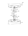
- FIG. 1 is a front view showing an example of a test piece used in the thermal barrier coating test method according to the first embodiment.
- FIG. 2 is a graph showing a required range of dimensions of the test piece according to the first embodiment.
- FIG. 3 is a schematic view showing an example of the structure of a test apparatus used in the thermal barrier coating test method according to the first embodiment.
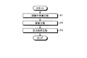
- FIG. 4 is a flowchart showing an outline of a thermal barrier coating test method.
- FIG. 5 is a graph showing an example of a strain gauge measurement result.
- FIG. 6 is a graph showing the evaluation results of the test piece according to the second embodiment.
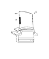
- FIG. 7 is a perspective view showing an example of a moving blade having a curved portion to which a compressive stress is applied, to which a thermal barrier coating is applied.
- FIG. 1 is a front view showing an example of a test piece used in the thermal barrier coating test method according to the first embodiment.
- FIG. 2 is a graph showing a required range of dimensions of the test piece according
- FIG. 8 is a schematic view showing a state in which a thermal barrier coating is performed on the moving blade shown in FIG.
- FIG. 9 is a schematic view showing a conventional test piece.
- FIG. 10 is a schematic view showing a conventional test piece.
- FIG. 11 is a schematic view showing a conventional test method.
- FIG. 1 is a front view showing an example of a test piece used in the thermal barrier coating test method according to the first embodiment.
- the test piece 1 simulates a curved portion 104 (see FIG. 7) including a range in which a high compressive stress is acting on a moving blade 100 (see FIG. 7) of a gas turbine that is an actual machine to be evaluated.
- the test piece 1 includes a main body 2 and a thermal barrier coating layer 3 formed on the surface of the main body 2.
- the main body 2 is a base material for the test piece 1.
- the main body 2 is made of the same heat-resistant alloy as the base material of the blade 102 (see FIG. 7) of the rotor blade 100.
- the main body 2 is cut out from the material ingot and formed into a plate shape.
- the main body 2 has a thickness that does not deform inadvertently when a predetermined compressive stress is applied.
- the main body 2 is preferably about 5 mm to 15 mm thick.
- the main body 2 includes a pair of arm parts 21, a bending part 22, and a pair of round holes 23.
- the pair of arm portions 21 are arranged to face each other. More specifically, the pair of arm portions 21 are arranged so as to be separated from each other in the direction from the proximal end portion 211 toward the distal end portion 212.
- the pair of arm portions 21 are formed in a shape that can be easily attached to the compression test apparatus 310 (see FIG. 3).
- the bending portion 22 is disposed between the base end portions 211 of the pair of arm portions 21.
- the pair of arm portions 21 and the bending portion 22 are integrally formed.
- the curved portion 22 has a curved surface 22a curved with a radius of curvature R.
- the curvature radius R of the curved portion 22 is preferably in the range of 3 mm or more and 7 mm or less together with the curvature radius of the curved portion 104 of the moving blade 100 of the gas turbine.
- the thickness hs of the curved portion 22 is preferably in the range of 3 mm or more and 7 mm or less, together with the thickness of the curved portion 104 of the moving blade 100 of the gas turbine.
- the pair of round holes 23 are formed so as to penetrate the tip portions 212 of the pair of arm portions 21 in the plate thickness direction.
- the pair of round holes 23 are arranged to face each other.
- the round hole 23 has a diameter through which the pin 315 of the compression test apparatus 310 is slidably inserted. In the present embodiment, the diameter of the round hole 23 is 5.5 mm.
- the thermal barrier coating layer 3 protects the main body 2 from high temperatures.
- the thermal barrier coating layer 3 is formed on the inner peripheral surface 2 a of the main body 2.
- the thermal barrier coating layer 3 is formed by the same method as the moving blade 100 of the gas turbine.
- a position of the thermal barrier coating layer 3 corresponding to the curved surface 22 a of the curved portion 22 of the test piece 1 is referred to as a curved portion 31.
- the thickness hc of the thermal barrier coating layer 3 is preferably in the range of 0.3 mm or more and 1.5 mm or less, together with the thickness of the thermal barrier coating layer of the moving blade 100 of the gas turbine.
- the thermal barrier coating layer 3 is formed by forming a bond coat layer as a metal bonding layer on the inner peripheral surface 2a of the main body 2 and laminating a ceramic layer made of oxide ceramics on the bond coat layer by a film forming method such as thermal spraying. Is formed.
- the bond coat layer is, for example, an MCrAlY alloy (M is Co, Ni, or a combination thereof).
- the ceramic layer is a ZrO 2 based material, for example, YSZ (yttria stabilized zirconia) which is ZrO 2 partially or completely stabilized with Y 2 O 3 .
- the distance H between the center O1 of the pair of round holes 23 and the center O2 of the curvature radius R is equal to the curvature radius R of the curved portion 22 and the thickness hc of the thermal barrier coating layer 3. And a value calculated based on the thickness hs of the bending portion 22.
- the distance H is calculated by FEM (Finite Element Method) on the curved portion 31 of the thermal barrier coating layer 3, the compressive stress that caused damage to the thermal barrier coating layer 3 in the test, and the curved portion 104 of the moving blade 100 of the gas turbine, for example.
- the dimensions are such that the compressive stress calculated in step 1 is covered.
- FIG. 2 is a graph showing a required range of dimensions of the test piece according to the first embodiment.
- the horizontal axis represents the radius of curvature R0 of the curved portion 31 of the thermal barrier coating layer 3
- the vertical axis represents the radius of curvature R / distance H of the curved portion 22, and the thermal barrier coating layer 3 for each thickness hs of the curved portion 22.
- the required range of the dimension of the distance H when the thickness hc is changed is shown.
- the thickness hs of the curved portion 22 is 3 mm, 5 mm, and 7 mm
- the thickness hc of the thermal barrier coating layer 3 is 0.3 mm, 1.0 mm, and 1.5 mm for each thickness hs.
- the required range of the dimension of the distance H when changed to The distance H should just be more than the value shown with a graph.
- test piece 1 when the distance H is 85 mm are as follows.
- the length L1 of the main body 2 in the vertical direction is 700 mm.
- the main body 2 has a lateral length L2 of 240 mm.
- the longitudinal length L3 of the distal end portion 212 of the arm portion 21 is 115 mm.
- the lateral length L4 of the distal end portion 212 of the arm portion 21 is 110 mm.
- the length L5 from the end surface 212a of the front end portion 212 of the round hole 23 is 70 mm.
- a length L6 from the end surface 212b of the tip end portion 212 of the round hole 23 is 65 mm.
- FIG. 3 is a schematic view showing an example of the structure of a test apparatus used in the thermal barrier coating test method according to the first embodiment.
- the compression test apparatus 310 includes a lower base 311, a lower holding part 312 fixed to the lower base 311, an upper base 313, an upper holding part 314 fixed to the upper base 313, and a pair Pin 315.
- the pair of pins 315 are inserted into an insertion hole 312 a formed in the lower holding portion 312 and an insertion hole 314 a formed in the upper holding portion 314.
- the pair of pins 315 are rotatably supported by the insertion hole 312a of the lower holding part 312 and the insertion hole 314a of the upper holding part 314.
- the pin 315 has such strength that it does not deform when a predetermined compressive stress is applied to the test piece 1.
- the diameter of the pin 315 is about 5 mm.
- the pin 315 has an axial length longer than the thickness of the test piece 1.
- the test piece 1 is attached to the compression test apparatus 310 via a pair of pins 315.
- the compression test apparatus 310 applies a compressive stress in a direction in which the pair of arm portions 21 are brought close to the mounted test piece 1.
- FIG. 4 is a flowchart showing an outline of a thermal barrier coating test method.
- the test method for the thermal barrier coating according to the present embodiment evaluates the presence or absence of damage to the thermal barrier coating formed on the curved portion where the compressive stress acts.
- the test method for the thermal barrier coating includes a test piece preparation step P1, a mounting step P2, and a stress loading step P3.
- each of the processes P1 to P3 will be described in detail.
- the test piece preparation process P1 includes a pair of arm portions 21, a curved portion 22 disposed between the pair of arm portions 21, and a thermal barrier coating layer 3 formed on the inner peripheral surface 2a of the main body portion 2.
- a test piece 1 having the following is prepared. More specifically, first, the distance H between the center O1 of the pair of round holes 23 and the center O2 of the radius of curvature R, the radius of curvature R of the curved portion 22, the thickness hc of the thermal barrier coating layer 3, and the curved portion 22 It calculates based on thickness hs. Based on the calculated distance H, other dimensions of the main body 2 are calculated. And based on the calculated dimension, the main-body part 2 is cut out from the ingot of material.
- a pair of round hole 23 is penetrated and formed in the thickness direction at the front-end
- the thermal-insulation coating layer 3 is formed in the procedure similar to a real machine on the internal peripheral surface 2a of the cut-out main-body part 2. FIG. In this way, the test piece 1 is created in the test piece preparation step P1.
- the radius of curvature R of the curved portion 22 is combined with the radius of curvature of the curved portion 104 of the moving blade 100 of the gas turbine to be in the range of 3 mm or more and 7 mm or less.
- the curvature radius R of the curved portion 22 is 6 mm.
- the thickness hs of the curved portion 22 is preferably in the range of 3 mm or more and 7 mm or less, together with the thickness of the curved portion 104 of the moving blade 100 of the gas turbine. In the present embodiment, the thickness hs of the curved portion 22 is 3 mm.
- the thickness hc of the thermal barrier coating layer 3 is preferably in the range of 0.3 mm or more and 1.5 mm or less, together with the thickness of the thermal barrier coating layer of the moving blade 100 of the gas turbine. In the present embodiment, the thickness hc of the thermal barrier coating layer 3 is 1.5 mm.
- the test piece 1 is mounted on the compression test apparatus 310 after the test piece preparation step P1. More specifically, the pair of pins 315 are inserted into the pair of round holes 23 of the test piece 1, and the test piece 1 is attached to the compression test apparatus 310. The pair of pins 315 is rotatable with respect to the lower holding portion 312 and the upper holding portion 314 and is rotatable with respect to the pair of round holes 23 of the test piece 1.
- the compression test apparatus 310 applies a compressive stress in a direction in which the pair of arms 21 are brought closer to the test piece 1 via the pair of pins 315.
- a load is applied in the direction in which the compressive stress acts on the thermal barrier coating layer 3 in the same manner as the stress field of the actual machine.
- a strain gauge 320 is first attached to the curved portion 31 of the thermal barrier coating layer 3 of the test piece 1.
- the strain gauge 320 is, for example, a differential transformer type extensometer.
- compressive stress is applied to the test piece 1 by the compression test apparatus 310.
- the strain gauge 320 measures the strain of the curved portion 31 of the thermal barrier coating layer 3 of the test piece 1.
- the strain gauge 320 outputs the measurement result to a control device (not shown) and stores it in the storage device.
- the control device displays the measurement result of the strain gauge 320 on the display device. On the display device, for example, the measurement result is displayed in a graph as shown in FIG.
- FIG. 5 is a graph showing an example of a strain gauge measurement result.
- the horizontal axis represents the displacement ⁇
- the vertical axis represents the thermal barrier coating layer surface strain ⁇ .
- the thermal barrier coating layer surface strain ⁇ causes discontinuities when damage occurs.
- the thermal barrier coating layer surface strain ⁇ increases as the displacement ⁇ increases.
- the thermal barrier coating layer surface strain ⁇ is ⁇ c
- the thermal barrier coating layer surface strain ⁇ is discontinuous.
- the thermal barrier coating layer 3 was damaged when the thermal barrier coating layer surface strain ⁇ was ⁇ c.
- the thermal barrier coating layer surface strain ⁇ in which damage has occurred is defined as the damage limit strain ⁇ c.
- the inner peripheral surface 2a of the main body 2 of the test piece 1 simulating the curved portion 104 including the range in which the high compressive stress of the moving blade 100 of the gas turbine is acting.
- the thermal barrier coating layer 3 is formed in the same procedure as the actual machine. Then, similarly to the stress field of the actual machine, a load is applied in the direction in which the compressive stress acts on the thermal barrier coating layer 3, and the strain of the curved portion 31 of the thermal barrier coating layer 3 is measured. Thereby, this embodiment can evaluate accurately the presence or absence of the damage in the curved part 31 of the thermal-insulation coating layer 3.
- test piece 1 simulates a curved portion 104 including a range in which a high compressive stress of the moving blade 100 of the gas turbine is applied, this embodiment is formed in the curved portion 104 of the moving blade 100 of the gas turbine. The presence or absence of damage to the thermal barrier coating can be accurately evaluated.
- the present embodiment by accurately evaluating the presence or absence of damage to the curved portion 31 of the thermal barrier coating layer 3 in the test piece 1, it is possible to accurately evaluate whether or not the thermal barrier coating of the actual machine is damaged.
- FIG. 7 is a perspective view showing an example of a moving blade having a curved portion to which a compressive stress is applied, to which a thermal barrier coating is applied.
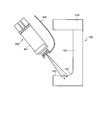
- FIG. 8 is a schematic view showing a state in which a thermal barrier coating is performed on the moving blade shown in FIG. As shown in FIG. 8, the moving blade 100 is disposed between the platform 103 and the masking jig 110.
- the thermal spraying device 300 When spraying the periphery of the curved portion 104 with the thermal spraying device 300, the thermal spraying device 300 is tilted with respect to the platform 103 so that the main body 301 and the supply pipe 302 do not interfere with the masking jig 110. To do. Compared with the case where the thermal spraying apparatus 300 is constructed in a state of being upright with respect to the construction part, the beam diameter X by the thermal spraying apparatus 300 is enlarged. Thereby, there is a possibility that the thermal barrier coating agent is difficult to adhere to the curved portion 104. If the number of thermal spray passes is increased so that the thermal barrier coating layer has a predetermined thickness, the thickness around the curved portion 104 may become thicker than other portions. As described above, the curved portions of the blades of the gas turbine and the combustor members are difficult to construct, and therefore it is required to appropriately evaluate the quality of the thermal barrier coating layer.
- the thermal barrier coating formed on the curved portion 104 of the moving blade 100 of the gas turbine is determined.
- the presence or absence of damage can be accurately evaluated.
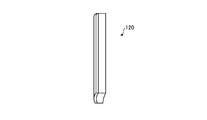
- the conventional method uses a test piece 120 taken from the blade portion 102 of the moving blade 100 of the gas turbine and extending in the axial direction in a direction perpendicular to the axial direction or in the axial direction. A load is applied in the direction along FIG. 9 is a schematic view showing a conventional test piece.
- FIG. 10 is a schematic view showing a conventional test piece.
- FIG. 11 is a schematic view showing a conventional test method.
- the strain is measured by the test piece 120 extending in the axial direction instead of the curved portion 104 (see FIG. 7) on which the high compressive stress of the moving blade 100 of the gas turbine acts. For this reason, in the conventional method, the presence or absence of damage cannot be evaluated by the shape of the curved portion 104 where a high compressive stress acts on the thermal barrier coating layer 3.
- the compressive stress is applied to the curved portion 31 of the thermal barrier coating layer 3 of the test piece 1, it is possible to more accurately evaluate the presence or absence of damage in the curved portion 31 of the thermal barrier coating layer 3. .
- this embodiment forms in the curved part 104 where the high compressive stress of the moving blade 100 of a gas turbine acts by evaluating the presence or absence of the damage in the curved part 31 of the thermal-insulation coating layer 3 of the test piece 1. The presence or absence of damage to the applied thermal barrier coating can be accurately evaluated.
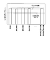
- FIG. 6 is a graph showing the evaluation results of the test piece according to the second embodiment.
- parts that are different from the first embodiment will be described in order to avoid duplicate descriptions, and parts that have the same configuration as the first embodiment will be given the same reference numerals or corresponding reference numerals. To do.
- the test piece 1 is cut out from the moving blade 100 of the gas turbine that is the actual machine. More specifically, in the test piece preparation step P1, the distance H between the center O1 of the pair of round holes 23 and the center O2 of the curvature radius R including the curved portion 104 of the moving blade 100 is equal to the curvature radius R of the bending portion 22. Then, the thermal barrier coating layer 3 is cut out to have a value calculated based on the thickness hc of the thermal barrier coating layer 3 and the thickness hs of the curved portion 22. And based on the calculated dimension, a pair of round hole 23 is formed in the front-end
- the specimen 1 may be cut out from the moving blade 100 of the gas turbine before or after operation. More specifically, when it is desired to evaluate the presence or absence of damage to the thermal barrier coating of the moving blade 100 of the gas turbine before operation, the test piece 1 may be cut out from the moving blade 100 of the gas turbine before operation. When it is desired to evaluate the presence or absence of damage to the thermal barrier coating on the moving blade 100 of the gas turbine after operation, the test piece 1 may be cut out from the moving blade 100 of the gas turbine after operation.
- the mounting process P2 and the stress loading process P3 are performed in the same manner as in the first embodiment.
- the evaluation method of this embodiment will be described with reference to FIG.
- the graph shows the damage limit strain ⁇ c for each test piece 1 cut out from the moving blade 100 of the gas turbine before operation.
- a solid line shows the part generation
- the broken line indicates the allowable strain range, in other words, the variation range. From the graph, the evaluation target wing has a limit value that is higher than the strain generated by the solid line in which the damage limit strain ⁇ c falls within the variation range. For this reason, it can be judged that the evaluation target wing has no problem in quality. The evaluation target wing determined in this way does not need to be repaired.
- the test piece 1 is cut out from the moving blade 100 of the gas turbine before or after operation, and the strength of the thermal barrier coating formed on the moving blade 100 of the gas turbine is measured. To do.
- this embodiment it is possible to accurately evaluate the presence or absence of damage to the thermal barrier coating formed on the moving blade 100 of the gas turbine. Thereby, this embodiment can improve the precision of quality control of the moving blade 100 of a gas turbine. Or this embodiment can improve the precision of the deterioration diagnosis of the moving blade 100 of a gas turbine more.
- test piece 1 has been described as imitating the moving blade 100 of the gas turbine, it is not limited to this.
- the test piece 1 can also be applied to other members having a curved portion on which a compressive stress is applied, for example, a curved portion of a combustor, to which a thermal barrier coating is applied.
Landscapes
- Physics & Mathematics (AREA)
- Health & Medical Sciences (AREA)
- Life Sciences & Earth Sciences (AREA)
- Chemical & Material Sciences (AREA)
- Analytical Chemistry (AREA)
- Biochemistry (AREA)
- General Health & Medical Sciences (AREA)
- General Physics & Mathematics (AREA)
- Immunology (AREA)
- Pathology (AREA)
- Investigating Strength Of Materials By Application Of Mechanical Stress (AREA)
Abstract
一対のアーム部21と、一対のアーム部21の間の湾曲部22と、湾曲部22の湾曲面22a上の遮熱コーティング層3とを有する試験片1を準備する試験片準備工程と、試験片準備工程の実施後に、試験片1を圧縮試験装置に装着する装着工程と、装着工程の実施後に、圧縮試験装置で、試験片1に対して一対のアーム部21を近づける方向に圧縮応力を負荷する応力負荷工程とを含む。
Description
本発明は、圧縮応力が作用する湾曲部に形成された遮熱コーティングの損傷の有無を評価する遮熱コーティングの試験方法及び試験片に関する。
例えば、ガスタービンの翼および燃焼器の部材などのに表面には、遮熱性および耐久性を向上させるために、遮熱コーティング(TBC:Thermal Barrier Coating)層が形成されている。遮熱コーティング層は高温環境下に長期間さらされるので、遮熱コーティング層が損傷するおそれがある。遮熱コーティング層が損傷すると、遮熱コーティング層の下の基材の損傷につながるおそれがある。そこで、遮熱コーティング層を有する部材を評価する方法や装置が知られている(例えば、特許文献1参照)。
特許文献1に記載された技術では、実機である動翼において最も疲労損傷が進行してき裂が伸びている部位から試験片を採取する。試験片は、動翼の前縁に沿い、径方向に沿って延びる棒状の形状である。そして、試験片に、試験片の軸線方向に対して垂直な方向に沿って繰り返し曲げ荷重を負荷する。このように、特許文献1に記載された技術は、湾曲部を有していない試験片に応力を負荷する。
ガスタービンの翼および燃焼器の部材の湾曲部は、他部より高い圧縮応力が作用しているので、遮熱コーティング層の品質を適切に評価することが求められている。しかも、湾曲部は、遮熱コーティングの施工が他の部分に比べて難しく、遮熱コーティングの品質を均一に保つことが難しい。このため、ガスタービンの翼および燃焼器の部材の湾曲部は、遮熱コーティング層の品質を適切に評価することが求められている。このように、圧縮応力が作用する湾曲部に形成された遮熱コーティングについて、損傷の有無を正確に評価することが求められている。
本発明は、このような実情に鑑みてなされたものであり、圧縮応力が作用する湾曲部に形成された遮熱コーティングの損傷の有無を正確に評価することができる遮熱コーティングの試験方法及び試験片を提供することを目的とする。
本発明の遮熱コーティングの試験方法は、圧縮応力が作用する湾曲部に形成された遮熱コーティングの損傷の有無を評価する遮熱コーティングの試験方法であって、一対のアーム部と、前記一対のアーム部の間に配置された湾曲部と、前記湾曲部の湾曲面上の遮熱コーティング層とを有する試験片を準備する試験片準備工程と、前記試験片準備工程の実施後に、前記試験片を圧縮試験装置に装着する装着工程と、前記装着工程の実施後に、前記圧縮試験装置で、前記試験片に対して前記一対のアーム部を近づける方向に圧縮応力を負荷する応力負荷工程と、を含むことを特徴とする。
この方法によれば、圧縮応力が作用する湾曲部に形成された遮熱コーティングの損傷の有無を正確に評価することができる。
本発明の遮熱コーティングの試験方法における、前記試験片準備工程は、前記一対のアーム部に、板厚方向に貫通する一対の丸孔を形成し、前記装着工程は、前記一対の丸孔に挿通したピンを介して、前記試験片を前記圧縮試験装置に装着し、前記応力負荷工程は、前記ピンを介して、前記試験片に対して前記一対のアーム部を近づける方向に圧縮応力を負荷することを特徴とする。この方法によれば、曲げモーメントの影響を軽減し、圧縮応力が作用する湾曲部に形成された遮熱コーティングの損傷の有無を正確に評価することができる。
本発明の遮熱コーティングの試験方法における、前記試験片準備工程は、前記湾曲部の曲率半径Rを評価対象である実機の湾曲部の曲率半径の値の範囲内とし、前記遮熱コーティング層の厚さhcを前記実機の遮熱コーティング層の厚さの値の範囲内とし、前記湾曲部の厚さhsを前記実機の湾曲部の厚さの値の範囲内とし、前記一対の丸孔の中心と前記曲率半径Rの中心との距離Hを、前記曲率半径Rと、前記厚さhcと、前記厚さhsとに基づいて算出される値とすることを特徴とする。この方法によれば、圧縮応力が作用する湾曲部に形成された遮熱コーティングの損傷の有無を正確に評価することができる。
本発明の遮熱コーティングの試験方法における、前記試験片準備工程は、前記曲率半径Rを3mm以上、7mm以下の範囲内とし、前記厚さhcを0.3mm以上、1.5mm以下の範囲内とし、前記厚さhsを3mm以上、7mm以下の範囲内とすることを特徴とする。この方法によれば、圧縮応力が作用する湾曲部に形成された遮熱コーティングの損傷の有無を正確に評価することができる。
本発明の試験片は、圧縮応力が作用する湾曲部に形成された遮熱コーティングの損傷の有無を評価する遮熱コーティングの試験方法で使用される試験片であって、一対のアーム部と、前記一対のアーム部の間に配置された湾曲部と、前記湾曲部の湾曲面上の遮熱コーティング層と、を備えることを特徴とする。
この構成によれば、圧縮応力が作用する湾曲部に形成された遮熱コーティングの損傷の有無を正確に評価することができる。
本発明の試験片は、前記一対のアーム部に、前記一対のアーム部を板厚方向に貫通する一対の丸孔を備え、前記一対の丸孔に挿通したピンを介して、圧縮試験装置に装着されることを特徴とする。この構成によれば、曲げモーメントの影響を軽減し、圧縮応力が作用する湾曲部に形成された遮熱コーティングの損傷の有無を正確に評価することができる。
本発明の試験片は、前記湾曲部の曲率半径Rは、評価対象である実機の湾曲部の曲率半径の値の範囲内であり、前記遮熱コーティング層の厚さhcは、前記実機の遮熱コーティング層の厚さの値の範囲内であり、前記湾曲部の厚さhsは、前記実機の湾曲部の厚さの値の範囲内であり、前記一対の丸孔の中心と前記曲率半径Rの中心との距離Hは、前記曲率半径Rと、前記厚さhcと、前記厚さhsとに基づいて算出される値であることを特徴とする。この構成によれば、圧縮応力が作用する湾曲部に形成された遮熱コーティングの損傷の有無を正確に評価することができる。
本発明の試験片は、前記曲率半径Rは、3mm以上、7mm以下の範囲内であり、前記厚さhcは、0.3mm以上、1.5mm以下の範囲内であり、前記厚さhsは、3mm以上、7mm以下の範囲内であることを特徴とする。この構成によれば、圧縮応力が作用する湾曲部に形成された遮熱コーティングの損傷の有無を正確に評価することができる。
本発明によれば、圧縮応力が作用する湾曲部に形成された遮熱コーティングの損傷の有無を正確に評価することができる。
以下、本発明の実施の形態について、添付図面を参照して詳細に説明する。なお、この実施形態によりこの発明が限定されるものではない。また、下記実施形態における構成要素には、当業者が置換可能かつ容易なもの、あるいは実質的に同一のものが含まれる。さらに、以下に記載した構成要素は適宜組み合わせることが可能であり、また、実施形態が複数ある場合には、各実施形態を組み合わせることも可能である。
(第一実施形態)
図1を用いて、試験片1について説明する。図1は、第一実施形態に係る遮熱コーティングの試験方法で使用される試験片の一例を示す正面図である。試験片1は、評価対象の実機であるガスタービンの動翼100(図7参照)の高い圧縮応力が作用している範囲を含む湾曲部104(図7参照)を模している。試験片1は、本体部2と、本体部2の表面に形成された遮熱コーティング層3とを備える。
図1を用いて、試験片1について説明する。図1は、第一実施形態に係る遮熱コーティングの試験方法で使用される試験片の一例を示す正面図である。試験片1は、評価対象の実機であるガスタービンの動翼100(図7参照)の高い圧縮応力が作用している範囲を含む湾曲部104(図7参照)を模している。試験片1は、本体部2と、本体部2の表面に形成された遮熱コーティング層3とを備える。
本体部2は、試験片1の基材である。本体部2は、動翼100の翼部102(図7参照)の基材と同じ耐熱合金で構成されている。本体部2は、材料のインゴットから切り出して板状に形成される。本体部2は、所定の圧縮応力を負荷した際に、不用意に変形しない程度の板厚を有する。本体部2は、例えば、板厚5mm以上、15mm以下程度とすることが好ましい。本体部2は、一対のアーム部21と、湾曲部22と、一対の丸孔23とを有する。
一対のアーム部21は、向かい合って配置されている。より詳しくは、一対のアーム部21は、基端部211から先端部212に向かうにつれて、互いに離れるように配置されている。一対のアーム部21は、圧縮試験装置310(図3参照)に装着しやすい形状に形成されている。一対のアーム部21の基端部211の間に、湾曲部22が配置されている。一対のアーム部21と湾曲部22とは、一体に形成されている。
湾曲部22は、曲率半径Rで湾曲した湾曲面22aを有する。湾曲部22の曲率半径Rは、ガスタービンの動翼100の湾曲部104の曲率半径と合わせて、3mm以上、7mm以下の範囲内とすることが好ましい。湾曲部22の厚さhsは、ガスタービンの動翼100の湾曲部104の厚さと合わせて、3mm以上、7mm以下の範囲内とすることが好ましい。
一対の丸孔23は、一対のアーム部21の先端部212を板厚方向に貫通して形成されている。一対の丸孔23は、向かい合って配置されている。丸孔23は、圧縮試験装置310のピン315が摺動自在に挿通される径を有する。本実施形態では、丸孔23の直径は、5.5mmである。
遮熱コーティング層3は、本体部2を高温から保護する。遮熱コーティング層3は、本体部2の内周面2a上に成膜されている。遮熱コーティング層3は、ガスタービンの動翼100と同じ方法で形成されている。遮熱コーティング層3の、試験片1の湾曲部22の湾曲面22aに対応する位置を、湾曲部31という。
遮熱コーティング層3の厚さhcは、ガスタービンの動翼100の遮熱コーティング層の厚さと合わせて、0.3mm以上、1.5mm以下の範囲内とすることが好ましい。
遮熱コーティング層3は、本体部2の内周面2aに、金属結合層であるボンドコート層を形成し、ボンドコート層上に溶射等の成膜方法によって酸化物セラミックスからなるセラミックス層を積層して形成されている。ボンドコート層は、例えば、MCrAlY合金(Mは、Co、Ni、または、これらの組み合わせ)である。セラミックス層としては、ZrO2系の材料、例えば、Y2O3で部分安定化または完全安定化したZrO2であるYSZ(イットリア安定化ジルコニア)である。
このように構成された試験片1において、一対の丸孔23の中心O1と曲率半径Rの中心O2との距離Hは、湾曲部22の曲率半径Rと、遮熱コーティング層3の厚さhcと、湾曲部22の厚さhsとに基づいて算出される値とする。距離Hは、遮熱コーティング層3の湾曲部31に、試験で遮熱コーティング層3に損傷を生じた圧縮応力と、ガスタービンの動翼100の例えば湾曲部104についてFEM(Finite Element Method)計算で算出した圧縮応力とを網羅して負荷するような寸法とする。
図2を用いて、距離Hの算出方法を説明する。図2は、第一実施形態に係る試験片の寸法の要求範囲を示すグラフである。グラフは、横軸を遮熱コーティング層3の湾曲部31の曲率半径R0、縦軸を湾曲部22の曲率半径R/距離Hとし、湾曲部22の厚さhsごとに、遮熱コーティング層3の厚さhcを変えた場合の、距離Hの寸法の要求範囲を示す。グラフは、例として、湾曲部22の厚さhsを3mm、5mm、7mmとし、それぞれの厚さhsごとに、遮熱コーティング層3の厚さhcを0.3mm、1.0mm、1.5mmと変えた場合の、距離Hの寸法の要求範囲を示す。距離Hは、グラフで示される値以上であればよい。
本実施形態において、距離Hを、85mmとしたときの、試験片1の他の寸法は次のとおりである。本体部2の縦方向の長さL1は、700mmである。本体部2の横方向の長さL2は、240mmである。アーム部21の先端部212の縦方向の長さL3は、115mmである。アーム部21の先端部212の横方向の長さL4は、110mmである。丸孔23の先端部212の端面212aからの長さL5は、70mmである。丸孔23の先端部212の端面212bからの長さL6は、65mmである。
図3を用いて、試験片1の圧縮試験を行う圧縮試験装置310について説明する。図3は、第一実施形態に係る遮熱コーティングの試験方法で使用される試験装置の構造の一例を示す概略図である。圧縮試験装置310は、下側基台311と、下側基台311に固定された下側保持部312と、上側基台313と、上側基台313に固定された上側保持部314と、一対のピン315とを有する。一対のピン315は、下側保持部312に形成された挿通孔312aと、上側保持部314に形成された挿通孔314aとに挿入されている。一対のピン315は、下側保持部312の挿通孔312aと、上側保持部314の挿通孔314aとで回転自在に支持されている。ピン315は、試験片1に所定の圧縮応力を負荷した際に変形しない程度の強度を有する。本実施形態では、ピン315の直径は、5mm程度とする。ピン315は、試験片1の板厚より長い軸方向の長さを有する。圧縮試験装置310には、一対のピン315を介して試験片1が装着される。圧縮試験装置310は、装着された試験片1に、一対のアーム部21を近づける方向の圧縮応力を負荷する。
次に、図4を用いて、試験片1を使用した遮熱コーティングの試験方法について説明する。図4は、遮熱コーティングの試験方法の概略を示すフロー図である。本実施形態に係る遮熱コーティングの試験方法は、圧縮応力が作用する湾曲部に形成された遮熱コーティングの損傷の有無を評価する。遮熱コーティングの試験方法は、試験片準備工程P1と、装着工程P2と、応力負荷工程P3とを含む。以下各工程P1~P3について詳細に説明する。
試験片準備工程P1は、一対のアーム部21と、一対のアーム部21の間に配置された湾曲部22と、本体部2の内周面2a上に成膜された遮熱コーティング層3とを有する試験片1を準備する。より詳しくは、まず、一対の丸孔23の中心O1と曲率半径Rの中心O2との距離Hを、湾曲部22の曲率半径Rと、遮熱コーティング層3の厚さhcと、湾曲部22の厚さhsとに基づいて算出する。そして、算出した距離Hに基づいて、本体部2の他の寸法を算出する。そして、算出した寸法に基づいて、本体部2を材料のインゴットから切り出す。そして、算出した寸法に基づいて、一対のアーム部21の先端部212に、一対の丸孔23を板厚方向に貫通して形成する。そして、切出した本体部2の内周面2aに、実機と同様の手順で、遮熱コーティング層3を形成する。このようにして、試験片準備工程P1で、試験片1が作成される。
試験片準備工程P1は、湾曲部22の曲率半径Rを、ガスタービンの動翼100の湾曲部104の曲率半径と合わせて、3mm以上、7mm以下の範囲内とすることが好ましい。本実施形態では、湾曲部22の曲率半径Rを、6mmとする。湾曲部22の厚さhsを、ガスタービンの動翼100の湾曲部104の厚さと合わせて、3mm以上、7mm以下の範囲内とすることが好ましい。本実施形態では、湾曲部22の厚さhsを、3mmとする。遮熱コーティング層3の厚さhcを、ガスタービンの動翼100の遮熱コーティング層の厚さと合わせて、0.3mm以上、1.5mm以下の範囲内とすることが好ましい。本実施形態では、遮熱コーティング層3の厚さhcは、1.5mmとする。
装着工程P2は、試験片準備工程P1の実施後に、試験片1を圧縮試験装置310に装着する。より詳しくは、試験片1の一対の丸孔23に一対のピン315を挿入して、試験片1を圧縮試験装置310に装着する。一対のピン315は、下側保持部312と上側保持部314とに対して回転自在、かつ、試験片1の一対の丸孔23に対して回転自在である。このように試験片1を圧縮試験装置310に装着することで、応力負荷工程P3において、試験片1における曲げモーメントの影響を無視することができる程度に軽減することができる。
応力負荷工程P3は、装着工程P2の実施後に、圧縮試験装置310で、試験片1に対して、一対のピン315を介して、一対のアーム部21を近づける方向の圧縮応力を負荷する。応力負荷工程P3は、実機の応力場と同様に、遮熱コーティング層3に圧縮応力が作用する方向に負荷をかける。より詳しくは、まず、試験片1の遮熱コーティング層3の湾曲部31に、ひずみゲージ320を貼着する。ひずみゲージ320は、例えば、差動トランス式伸び計である。そして、圧縮試験装置310で試験片1に圧縮応力を負荷する。ひずみゲージ320は、試験片1の遮熱コーティング層3の湾曲部31のひずみを測定する。ひずみゲージ320は、計測結果を図示しない制御装置に出力し、記憶装置に記憶させる。制御装置は、ひずみゲージ320の計測結果を表示装置で表示する。表示装置には、例えば、計測結果が図5に示すようなグラフで表示される。
図5を用いて、ひずみゲージ320の計測結果について説明する。図5は、ひずみゲージ計測結果の一例を示すグラフである。グラフは、横軸を変位δ、縦軸を遮熱コーティング層表面ひずみεとしている。遮熱コーティング層表面ひずみεは、損傷発生時に不連続点を生じる。このグラフでは、圧縮応力を負荷すると、変位δの増加にともなって、遮熱コーティング層表面ひずみεが増加する。そして、遮熱コーティング層表面ひずみεがεcのとき、遮熱コーティング層表面ひずみεが不連続である。これにより、遮熱コーティング層表面ひずみεがεcで遮熱コーティング層3が損傷したと推測される。このように、図5に示す例では、損傷が発生した遮熱コーティング層表面ひずみεを、損傷限界ひずみεcとする。
以上説明したように、本実施形態によれば、ガスタービンの動翼100の高い圧縮応力が作用している範囲を含む湾曲部104を模した試験片1の本体部2の内周面2a上に、実機と同様の手順で、遮熱コーティング層3を形成する。そして、実機の応力場と同様に、遮熱コーティング層3に圧縮応力が作用する方向に負荷をかけて、遮熱コーティング層3の湾曲部31のひずみを測定する。これにより、本実施形態は、遮熱コーティング層3の湾曲部31における損傷の有無を正確に評価することができる。試験片1はガスタービンの動翼100の高い圧縮応力が作用している範囲を含む湾曲部104を模しているので、本実施形態は、ガスタービンの動翼100の湾曲部104に形成された遮熱コーティングの損傷の有無を正確に評価することができる。
本実施形態によれば、試験片1において遮熱コーティング層3の湾曲部31における損傷の有無を正確に評価することで、実機の遮熱コーティングの損傷の有無を正確に評価することができる。
さらに、湾曲部104は、遮熱コーティングの施工が他の部分に比べて難しく、遮熱コーティングの品質を均一に保つことが難しい。図8を用いて、湾曲部104における遮熱コーティングの施工について説明する。図7は、遮熱コーティングが施された、圧縮応力が作用する湾曲部を有する動翼の一例を示す斜視図である。図8は、図7に示す動翼に遮熱コーティングを実施する状態を示す概略図である。図8に示すように、動翼100は、プラットフォーム103とマスキング治具110との間に配置されている。湾曲部104の周辺を溶射装置300で溶射する際に、本体部301および供給管302がマスキング治具110に干渉しないように、溶射装置300をプラットフォーム103に対して斜めに傾斜させた状態で施工する。溶射装置300を施工部に対して直立させた状態で施工した場合に比べて、溶射装置300によるビーム径Xが拡大する。これにより、遮熱コーティング剤が、湾曲部104に付着しにくいおそれがある。遮熱コーティング層が所定の厚みとなるように、溶射のパス数を増加させると、湾曲部104の周辺の厚さが他の部分よりも厚くなるおそれがある。このように、ガスタービンの翼および燃焼器の部材の湾曲部は、施工が難しいため、遮熱コーティング層の品質を適切に評価することが求められている。
本実施形態によれば、試験片1において遮熱コーティング層3の湾曲部31における損傷の有無を正確に評価することで、ガスタービンの動翼100の湾曲部104に形成された遮熱コーティングの損傷の有無を正確に評価することができる。
これに対して、従来の方法について説明する。図9ないし図11に示すように、従来の方法は、ガスタービンの動翼100の翼部102から採取した、軸線方向に延びた試験片120に、軸線方向と垂直な方向、または、軸線方向に沿った方向に荷重を負荷する。図9は、従来の試験片を示す概略図である。図10は、従来の試験片を示す概略図である。図11は、従来の試験方法を示す概略図である。このように、従来は、ガスタービンの動翼100の高い圧縮応力が作用する湾曲部104(図7参照)ではなく、軸線方向に延びた試験片120でひずみを測定する。このため、従来の方法では、遮熱コーティング層3に高い圧縮応力が作用する湾曲部104の形状で損傷の有無を評価することができない。
本実施形態によれば、試験片1の遮熱コーティング層3の湾曲部31に圧縮応力を負荷するので、遮熱コーティング層3の湾曲部31における損傷の有無をより正確に評価することができる。
このように、本実施形態は、試験片1の遮熱コーティング層3の湾曲部31における損傷の有無を評価することで、ガスタービンの動翼100の高い圧縮応力が作用する湾曲部104に形成された遮熱コーティングの損傷の有無を正確に評価することができる。
(第二実施形態)
次に、図6を参照して、本実施形態に係る遮熱コーティングの試験方法について説明する。図6は、第二実施形態に係る試験片の評価結果を示すグラフである。なお、本実施形態では、重複した記載を避けるべく、第一実施形態と異なる部分について説明し、第一実施形態と同様の構成である部分については、同じ符号又は対応する符号を付して説明する。
次に、図6を参照して、本実施形態に係る遮熱コーティングの試験方法について説明する。図6は、第二実施形態に係る試験片の評価結果を示すグラフである。なお、本実施形態では、重複した記載を避けるべく、第一実施形態と異なる部分について説明し、第一実施形態と同様の構成である部分については、同じ符号又は対応する符号を付して説明する。
試験片準備工程P1で、試験片1を、実機であるガスタービンの動翼100から切出して作成する。より詳しくは、試験片準備工程P1で、動翼100の湾曲部104を含み、一対の丸孔23の中心O1と曲率半径Rの中心O2との距離Hが、湾曲部22の曲率半径Rと、遮熱コーティング層3の厚さhcと、湾曲部22の厚さhsとに基づいて算出される値となるように切出す。そして、算出した寸法に基づいて、切出した試験片1の一対のアーム部21の先端部212に、一対の丸孔23を形成する。
試験片準備工程P1では、運転前または運転後のガスタービンの動翼100から試験片1の切出しを行えばよい。より詳しくは、運転前のガスタービンの動翼100の遮熱コーティングの損傷の有無を評価したい場合、運転前のガスタービンの動翼100から試験片1を切出せばよい。運転後のガスタービンの動翼100の遮熱コーティングの損傷の有無を評価したい場合、運転後のガスタービンの動翼100から試験片1を切出せばよい。
装着工程P2と応力負荷工程P3とは、第一実施形態と同様に実施する。
図6を用いて、本実施形態の評価方法について説明する。本実施形態では、運転前のガスタービンの動翼100の遮熱コーティングの損傷の有無を評価する。グラフは、運転前のガスタービンの動翼100から切出した試験片1ごとの損傷限界ひずみεcを示す。実線は、ガスタービンの動翼100の湾曲部104についてFEM計算で算出した当該部発生ひずみを示す。破線は、ひずみの許容範囲、言い換えると、ばらつき範囲を示す。グラフから、評価対象翼は、損傷限界ひずみεcがばらつき範囲内に収まり、実線の当該部発生ひずみより高い限界値である。このため、評価対象翼は品質に問題がないと判断することができる。このように判断された評価対象翼は、補修が不要である。
以上説明したように、本実施形態によれば、運転前または運転後のガスタービンの動翼100から試験片1を切出して、ガスタービンの動翼100に形成された遮熱コーティングの強度を測定する。本実施形態は、ガスタービンの動翼100に形成された遮熱コーティングの損傷の有無を正確に評価することができる。これにより、本実施形態は、ガスタービンの動翼100の品質管理の精度を向上することができる。または、本実施形態は、ガスタービンの動翼100の劣化診断の精度をより向上することができる。
試験片1は、ガスタービンの動翼100を模したものとして説明したが、これに限定されるものではない。試験片1は、遮熱コーティングが施された、圧縮応力が作用する湾曲部を有する他の部材、例えば、燃焼器の湾曲部についても適用することができる。
1 試験片
2 本体部
2a 内周面
21 アーム部
22 湾曲部
22a 湾曲面
23 丸孔
3 遮熱コーティング層
31 湾曲部
100 動翼
102 翼部
104 湾曲部
H 距離(丸孔と曲率半径の中心との距離)
hc 厚さ(遮熱コーティング層の厚さ)
hs 厚さ(湾曲部の厚さ)
R 曲率半径
2 本体部
2a 内周面
21 アーム部
22 湾曲部
22a 湾曲面
23 丸孔
3 遮熱コーティング層
31 湾曲部
100 動翼
102 翼部
104 湾曲部
H 距離(丸孔と曲率半径の中心との距離)
hc 厚さ(遮熱コーティング層の厚さ)
hs 厚さ(湾曲部の厚さ)
R 曲率半径
Claims (8)
- 圧縮応力が作用する湾曲部に形成された遮熱コーティングの損傷の有無を評価する遮熱コーティングの試験方法であって、
一対のアーム部と、前記一対のアーム部の間に配置された湾曲部と、前記湾曲部の湾曲面上の遮熱コーティング層とを有する試験片を準備する試験片準備工程と、
前記試験片準備工程の実施後に、前記試験片を圧縮試験装置に装着する装着工程と、
前記装着工程の実施後に、前記圧縮試験装置で、前記試験片に対して前記一対のアーム部を近づける方向に圧縮応力を負荷する応力負荷工程と、
を含むことを特徴とする遮熱コーティングの試験方法。 - 前記試験片準備工程は、前記一対のアーム部に、板厚方向に貫通する一対の丸孔を形成し、
前記装着工程は、前記一対の丸孔に挿通したピンを介して、前記試験片を前記圧縮試験装置に装着し、
前記応力負荷工程は、前記ピンを介して、前記試験片に対して前記一対のアーム部を近づける方向に圧縮応力を負荷することを特徴とする請求項1に記載の遮熱コーティングの試験方法。 - 前記試験片準備工程は、
前記湾曲部の曲率半径Rを評価対象である実機の湾曲部の曲率半径の値の範囲内とし、前記遮熱コーティング層の厚さhcを前記実機の遮熱コーティング層の厚さの値の範囲内とし、前記湾曲部の厚さhsを前記実機の湾曲部の厚さの値の範囲内とし、前記一対の丸孔の中心と前記曲率半径Rの中心との距離Hを、前記曲率半径Rと、前記厚さhcと、前記厚さhsとに基づいて算出される値とすることを特徴とする請求項1または2に記載の遮熱コーティングの試験方法。 - 前記試験片準備工程は、
前記曲率半径Rを3mm以上、7mm以下の範囲内とし、前記厚さhcを0.3mm以上、1.5mm以下の範囲内とし、前記厚さhsを3mm以上、7mm以下の範囲内とすることを特徴とする請求項3に記載の遮熱コーティングの試験方法。 - 圧縮応力が作用する湾曲部に形成された遮熱コーティングの損傷の有無を評価する遮熱コーティングの試験方法で使用される試験片であって、
一対のアーム部と、
前記一対のアーム部の間に配置された湾曲部と、
前記湾曲部の湾曲面上の遮熱コーティング層と、
を備えることを特徴とする試験片。 - 前記一対のアーム部に、前記一対のアーム部を板厚方向に貫通する一対の丸孔を備え、
前記一対の丸孔に挿通したピンを介して、圧縮試験装置に装着されることを特徴とする請求項5に記載の試験片。 - 前記湾曲部の曲率半径Rは、評価対象である実機の湾曲部の曲率半径の値の範囲内であり、
前記遮熱コーティング層の厚さhcは、前記実機の遮熱コーティング層の厚さの値の範囲内であり、
前記湾曲部の厚さhsは、前記実機の湾曲部の厚さの値の範囲内であり、
前記一対の丸孔の中心と前記曲率半径Rの中心との距離Hは、前記曲率半径Rと、前記厚さhcと、前記厚さhsとに基づいて算出される値であることを特徴とする請求項5または6に記載の試験片。 - 前記曲率半径Rは、3~7mmの範囲内であり、
前記厚さhcは、0.3~1.5mmの範囲内であり、
前記厚さhsは、3~7mmの範囲内であることを特徴とする請求項7に記載の試験片。
Priority Applications (3)
| Application Number | Priority Date | Filing Date | Title |
|---|---|---|---|
| DE112017006563.1T DE112017006563T5 (de) | 2016-12-26 | 2017-12-26 | Prüfverfahren und prüfkörper einer thermischen sperrbeschichtung |
| US16/473,337 US11493413B2 (en) | 2016-12-26 | 2017-12-26 | Testing method and test piece of thermal barrier coating |
| CN201780079867.2A CN110100163B (zh) | 2016-12-26 | 2017-12-26 | 隔热涂覆的试验方法以及试验片 |
Applications Claiming Priority (2)
| Application Number | Priority Date | Filing Date | Title |
|---|---|---|---|
| JP2016251455A JP6832153B2 (ja) | 2016-12-26 | 2016-12-26 | 遮熱コーティングの試験方法及び試験片 |
| JP2016-251455 | 2016-12-26 |
Publications (1)
| Publication Number | Publication Date |
|---|---|
| WO2018124086A1 true WO2018124086A1 (ja) | 2018-07-05 |
Family
ID=62707414
Family Applications (1)
| Application Number | Title | Priority Date | Filing Date |
|---|---|---|---|
| PCT/JP2017/046686 Ceased WO2018124086A1 (ja) | 2016-12-26 | 2017-12-26 | 遮熱コーティングの試験方法及び試験片 |
Country Status (5)
| Country | Link |
|---|---|
| US (1) | US11493413B2 (ja) |
| JP (1) | JP6832153B2 (ja) |
| CN (1) | CN110100163B (ja) |
| DE (1) | DE112017006563T5 (ja) |
| WO (1) | WO2018124086A1 (ja) |
Families Citing this family (4)
| Publication number | Priority date | Publication date | Assignee | Title |
|---|---|---|---|---|
| US12480850B2 (en) * | 2022-04-21 | 2025-11-25 | The Boeing Company | Tension load fixture and method for evaluating fracture behavior of a composite material |
| CN116626091B (zh) * | 2023-07-21 | 2023-09-29 | 江苏德励达新材料股份有限公司 | 一种聚氨酯材料耐热检测装置 |
| USD1097837S1 (en) * | 2024-05-20 | 2025-10-14 | Beacon NDT Services, LLC | Load testing tension beam apparatus |
| USD1097838S1 (en) * | 2024-05-20 | 2025-10-14 | Beacon NDT Services, LLC | Load testing linkage member |
Citations (3)
| Publication number | Priority date | Publication date | Assignee | Title |
|---|---|---|---|---|
| JPS6061644A (ja) * | 1983-09-14 | 1985-04-09 | Toshin Kogyo Kk | 材料腐食試験槽 |
| JP2004184238A (ja) * | 2002-12-03 | 2004-07-02 | Mitsubishi Heavy Ind Ltd | 加熱試験装置および加熱試験方法 |
| JP2004309217A (ja) * | 2003-04-03 | 2004-11-04 | Toshiba Corp | コーティング被膜疲労試験装置およびコーティング被膜疲労試験方法 |
Family Cites Families (7)
| Publication number | Priority date | Publication date | Assignee | Title |
|---|---|---|---|---|
| JP2001330542A (ja) | 2000-05-22 | 2001-11-30 | Toshiba Corp | ガスタービンコーティング部品の疲労寿命評価方法および疲労寿命評価装置 |
| JP2004012390A (ja) * | 2002-06-10 | 2004-01-15 | Mitsubishi Heavy Ind Ltd | 高温部品の遮熱コーティング材の品質評価法 |
| CN2758743Y (zh) * | 2004-12-28 | 2006-02-15 | 北京交通大学 | 拉压弯组合加载试件 |
| CN201355331Y (zh) * | 2008-09-24 | 2009-12-02 | 攀钢集团研究院有限公司 | 一种用于金属材料弯曲试验的试样 |
| US8739547B2 (en) * | 2011-06-23 | 2014-06-03 | United Technologies Corporation | Gas turbine engine joint having a metallic member, a CMC member, and a ceramic key |
| JP6209489B2 (ja) * | 2014-05-21 | 2017-10-04 | 株式会社コベルコ科研 | 熱疲労試験方法及び試験片 |
| JP6319663B2 (ja) * | 2014-11-11 | 2018-05-09 | 三菱重工業株式会社 | エロージョン試験装置、および、エロージョン試験方法 |
-
2016
- 2016-12-26 JP JP2016251455A patent/JP6832153B2/ja active Active
-
2017
- 2017-12-26 US US16/473,337 patent/US11493413B2/en active Active
- 2017-12-26 DE DE112017006563.1T patent/DE112017006563T5/de active Pending
- 2017-12-26 CN CN201780079867.2A patent/CN110100163B/zh active Active
- 2017-12-26 WO PCT/JP2017/046686 patent/WO2018124086A1/ja not_active Ceased
Patent Citations (3)
| Publication number | Priority date | Publication date | Assignee | Title |
|---|---|---|---|---|
| JPS6061644A (ja) * | 1983-09-14 | 1985-04-09 | Toshin Kogyo Kk | 材料腐食試験槽 |
| JP2004184238A (ja) * | 2002-12-03 | 2004-07-02 | Mitsubishi Heavy Ind Ltd | 加熱試験装置および加熱試験方法 |
| JP2004309217A (ja) * | 2003-04-03 | 2004-11-04 | Toshiba Corp | コーティング被膜疲労試験装置およびコーティング被膜疲労試験方法 |
Also Published As
| Publication number | Publication date |
|---|---|
| JP2018105695A (ja) | 2018-07-05 |
| CN110100163A (zh) | 2019-08-06 |
| JP6832153B2 (ja) | 2021-02-24 |
| US20200141847A1 (en) | 2020-05-07 |
| DE112017006563T5 (de) | 2019-10-10 |
| US11493413B2 (en) | 2022-11-08 |
| CN110100163B (zh) | 2022-06-21 |
Similar Documents
| Publication | Publication Date | Title |
|---|---|---|
| WO2018124086A1 (ja) | 遮熱コーティングの試験方法及び試験片 | |
| JP5791431B2 (ja) | 膜厚測定装置及び膜厚測定方法 | |
| US20160139029A1 (en) | Corrosion sensor for internal structure of machine | |
| Casavola et al. | Experimental and numerical study of static and fatigue properties of titanium alloy welded joints | |
| CN116189824B (zh) | 一种航空发动机用高温合金焊接接头疲劳寿命预测方法 | |
| JP2004309217A (ja) | コーティング被膜疲労試験装置およびコーティング被膜疲労試験方法 | |
| US20090038151A1 (en) | Method for establishing a location of an elevated stress region | |
| EP2158062B1 (en) | Turbine vane restoration system | |
| RU2643682C1 (ru) | Устройство для определения адгезионной прочности многослойного керамического теплозащитного покрытия | |
| US6935187B1 (en) | Test method for assessing thermal mechanical fatigue performance of a test material | |
| US6183882B1 (en) | In plane deflection coupon for monitoring and controlling of laser shock peening | |
| CN116223048A (zh) | 一种单晶高压涡轮工作叶片服役损伤评价方法 | |
| JP2004012390A (ja) | 高温部品の遮熱コーティング材の品質評価法 | |
| Kushan et al. | Failure analysis of an aircraft propeller | |
| JP6122669B2 (ja) | 高温機械用部品の余寿命評価方法 | |
| JP2003315251A (ja) | 耐熱鋼の高温損傷評価方法 | |
| CN110320117A (zh) | 基于单晶叶片蠕变性能的测试方法 | |
| Su et al. | Experimental investigation of the biaxial strength of thermal barrier coating system | |
| US11143620B2 (en) | Electromagnetic probe testing of bond coat | |
| Lee et al. | Failure investigation of fuel tubes of a jet engine augmenter assembly | |
| US11529674B2 (en) | Refractory metal core finishing technique | |
| Crowther | Non-destructive evaluation of coatings for land-based gas turbines using a multi-frequency eddy current technique | |
| JP6126962B2 (ja) | 溶接部材の寿命評価方法 | |
| JP2009074868A (ja) | ニッケル基合金部品の寿命推定方法 | |
| CN107315013B (zh) | 一种航空发动机涡轮叶片涂层破损的显色检查方法 |
Legal Events
| Date | Code | Title | Description |
|---|---|---|---|
| 121 | Ep: the epo has been informed by wipo that ep was designated in this application |
Ref document number: 17887365 Country of ref document: EP Kind code of ref document: A1 |
|
| 122 | Ep: pct application non-entry in european phase |
Ref document number: 17887365 Country of ref document: EP Kind code of ref document: A1 |