WO2018123781A1 - 複合管 - Google Patents
複合管 Download PDFInfo
- Publication number
- WO2018123781A1 WO2018123781A1 PCT/JP2017/045835 JP2017045835W WO2018123781A1 WO 2018123781 A1 WO2018123781 A1 WO 2018123781A1 JP 2017045835 W JP2017045835 W JP 2017045835W WO 2018123781 A1 WO2018123781 A1 WO 2018123781A1
- Authority
- WO
- WIPO (PCT)
- Prior art keywords
- resin layer
- porous resin
- coating layer
- layer
- tube
- Prior art date
Links
- 239000002131 composite material Substances 0.000 title claims abstract description 61
- 229920005989 resin Polymers 0.000 claims abstract description 217
- 239000011347 resin Substances 0.000 claims abstract description 217
- 239000000463 material Substances 0.000 claims abstract description 40
- 239000010410 layer Substances 0.000 claims description 185
- 239000011247 coating layer Substances 0.000 claims description 126
- 238000007906 compression Methods 0.000 claims description 53
- 230000006835 compression Effects 0.000 claims description 52
- JOYRKODLDBILNP-UHFFFAOYSA-N Ethyl urethane Chemical compound CCOC(N)=O JOYRKODLDBILNP-UHFFFAOYSA-N 0.000 claims description 29
- 230000002940 repellent Effects 0.000 abstract 1
- 239000005871 repellent Substances 0.000 abstract 1
- 239000006260 foam Substances 0.000 description 30
- 238000004519 manufacturing process Methods 0.000 description 24
- 238000000034 method Methods 0.000 description 22
- 239000000155 melt Substances 0.000 description 15
- 230000002093 peripheral effect Effects 0.000 description 14
- 229920001083 polybutene Polymers 0.000 description 11
- 238000004904 shortening Methods 0.000 description 11
- 239000011342 resin composition Substances 0.000 description 8
- 238000005520 cutting process Methods 0.000 description 7
- 229920001684 low density polyethylene Polymers 0.000 description 6
- 239000004702 low-density polyethylene Substances 0.000 description 6
- -1 polyethylene Polymers 0.000 description 6
- 239000004814 polyurethane Substances 0.000 description 6
- 229920002635 polyurethane Polymers 0.000 description 6
- 239000011148 porous material Substances 0.000 description 5
- 239000000654 additive Substances 0.000 description 4
- 230000000996 additive effect Effects 0.000 description 4
- 238000001816 cooling Methods 0.000 description 4
- 239000002994 raw material Substances 0.000 description 4
- 239000004698 Polyethylene Substances 0.000 description 3
- BZHJMEDXRYGGRV-UHFFFAOYSA-N Vinyl chloride Chemical compound ClC=C BZHJMEDXRYGGRV-UHFFFAOYSA-N 0.000 description 3
- 238000013459 approach Methods 0.000 description 3
- 230000000052 comparative effect Effects 0.000 description 3
- 150000001875 compounds Chemical class 0.000 description 3
- 239000000470 constituent Substances 0.000 description 3
- 238000005187 foaming Methods 0.000 description 3
- 238000005259 measurement Methods 0.000 description 3
- 239000000178 monomer Substances 0.000 description 3
- 229920000573 polyethylene Polymers 0.000 description 3
- 229920000098 polyolefin Polymers 0.000 description 3
- 238000012360 testing method Methods 0.000 description 3
- 239000004743 Polypropylene Substances 0.000 description 2
- 230000004323 axial length Effects 0.000 description 2
- 239000004703 cross-linked polyethylene Substances 0.000 description 2
- 229920003020 cross-linked polyethylene Polymers 0.000 description 2
- 239000000203 mixture Substances 0.000 description 2
- 229920001155 polypropylene Polymers 0.000 description 2
- 238000002360 preparation method Methods 0.000 description 2
- 238000011144 upstream manufacturing Methods 0.000 description 2
- 238000004804 winding Methods 0.000 description 2
- 101100493706 Caenorhabditis elegans bath-38 gene Proteins 0.000 description 1
- 239000004793 Polystyrene Substances 0.000 description 1
- 238000005452 bending Methods 0.000 description 1
- 230000015572 biosynthetic process Effects 0.000 description 1
- 230000003139 buffering effect Effects 0.000 description 1
- 239000003054 catalyst Substances 0.000 description 1
- 239000011248 coating agent Substances 0.000 description 1
- 238000000576 coating method Methods 0.000 description 1
- 238000010276 construction Methods 0.000 description 1
- 229920003244 diene elastomer Polymers 0.000 description 1
- JNSGIVNNHKGGRU-JYRVWZFOSA-N diethoxyphosphinothioyl (2z)-2-(2-amino-1,3-thiazol-4-yl)-2-methoxyiminoacetate Chemical group CCOP(=S)(OCC)OC(=O)C(=N/OC)\C1=CSC(N)=N1 JNSGIVNNHKGGRU-JYRVWZFOSA-N 0.000 description 1
- 238000011156 evaluation Methods 0.000 description 1
- 239000004088 foaming agent Substances 0.000 description 1
- 238000000465 moulding Methods 0.000 description 1
- 239000005056 polyisocyanate Substances 0.000 description 1
- 229920001228 polyisocyanate Polymers 0.000 description 1
- 229920005862 polyol Polymers 0.000 description 1
- 150000003077 polyols Chemical class 0.000 description 1
- 229920002223 polystyrene Polymers 0.000 description 1
- 238000003825 pressing Methods 0.000 description 1
- 238000012545 processing Methods 0.000 description 1
- 238000009751 slip forming Methods 0.000 description 1
- 239000003381 stabilizer Substances 0.000 description 1
- 229920003002 synthetic resin Polymers 0.000 description 1
- 239000000057 synthetic resin Substances 0.000 description 1
Images


Classifications
-
- B—PERFORMING OPERATIONS; TRANSPORTING
- B32—LAYERED PRODUCTS
- B32B—LAYERED PRODUCTS, i.e. PRODUCTS BUILT-UP OF STRATA OF FLAT OR NON-FLAT, e.g. CELLULAR OR HONEYCOMB, FORM
- B32B1/00—Layered products having a non-planar shape
- B32B1/08—Tubular products
-
- B—PERFORMING OPERATIONS; TRANSPORTING
- B32—LAYERED PRODUCTS
- B32B—LAYERED PRODUCTS, i.e. PRODUCTS BUILT-UP OF STRATA OF FLAT OR NON-FLAT, e.g. CELLULAR OR HONEYCOMB, FORM
- B32B27/00—Layered products comprising a layer of synthetic resin
- B32B27/06—Layered products comprising a layer of synthetic resin as the main or only constituent of a layer, which is next to another layer of the same or of a different material
- B32B27/065—Layered products comprising a layer of synthetic resin as the main or only constituent of a layer, which is next to another layer of the same or of a different material of foam
-
- B—PERFORMING OPERATIONS; TRANSPORTING
- B32—LAYERED PRODUCTS
- B32B—LAYERED PRODUCTS, i.e. PRODUCTS BUILT-UP OF STRATA OF FLAT OR NON-FLAT, e.g. CELLULAR OR HONEYCOMB, FORM
- B32B27/00—Layered products comprising a layer of synthetic resin
- B32B27/32—Layered products comprising a layer of synthetic resin comprising polyolefins
-
- B—PERFORMING OPERATIONS; TRANSPORTING
- B32—LAYERED PRODUCTS
- B32B—LAYERED PRODUCTS, i.e. PRODUCTS BUILT-UP OF STRATA OF FLAT OR NON-FLAT, e.g. CELLULAR OR HONEYCOMB, FORM
- B32B3/00—Layered products comprising a layer with external or internal discontinuities or unevennesses, or a layer of non-planar shape; Layered products comprising a layer having particular features of form
- B32B3/26—Layered products comprising a layer with external or internal discontinuities or unevennesses, or a layer of non-planar shape; Layered products comprising a layer having particular features of form characterised by a particular shape of the outline of the cross-section of a continuous layer; characterised by a layer with cavities or internal voids ; characterised by an apertured layer
- B32B3/28—Layered products comprising a layer with external or internal discontinuities or unevennesses, or a layer of non-planar shape; Layered products comprising a layer having particular features of form characterised by a particular shape of the outline of the cross-section of a continuous layer; characterised by a layer with cavities or internal voids ; characterised by an apertured layer characterised by a layer comprising a deformed thin sheet, i.e. the layer having its entire thickness deformed out of the plane, e.g. corrugated, crumpled
-
- B—PERFORMING OPERATIONS; TRANSPORTING
- B32—LAYERED PRODUCTS
- B32B—LAYERED PRODUCTS, i.e. PRODUCTS BUILT-UP OF STRATA OF FLAT OR NON-FLAT, e.g. CELLULAR OR HONEYCOMB, FORM
- B32B3/00—Layered products comprising a layer with external or internal discontinuities or unevennesses, or a layer of non-planar shape; Layered products comprising a layer having particular features of form
- B32B3/26—Layered products comprising a layer with external or internal discontinuities or unevennesses, or a layer of non-planar shape; Layered products comprising a layer having particular features of form characterised by a particular shape of the outline of the cross-section of a continuous layer; characterised by a layer with cavities or internal voids ; characterised by an apertured layer
- B32B3/30—Layered products comprising a layer with external or internal discontinuities or unevennesses, or a layer of non-planar shape; Layered products comprising a layer having particular features of form characterised by a particular shape of the outline of the cross-section of a continuous layer; characterised by a layer with cavities or internal voids ; characterised by an apertured layer characterised by a layer formed with recesses or projections, e.g. hollows, grooves, protuberances, ribs
-
- B—PERFORMING OPERATIONS; TRANSPORTING
- B32—LAYERED PRODUCTS
- B32B—LAYERED PRODUCTS, i.e. PRODUCTS BUILT-UP OF STRATA OF FLAT OR NON-FLAT, e.g. CELLULAR OR HONEYCOMB, FORM
- B32B5/00—Layered products characterised by the non- homogeneity or physical structure, i.e. comprising a fibrous, filamentary, particulate or foam layer; Layered products characterised by having a layer differing constitutionally or physically in different parts
- B32B5/18—Layered products characterised by the non- homogeneity or physical structure, i.e. comprising a fibrous, filamentary, particulate or foam layer; Layered products characterised by having a layer differing constitutionally or physically in different parts characterised by features of a layer of foamed material
-
- B—PERFORMING OPERATIONS; TRANSPORTING
- B32—LAYERED PRODUCTS
- B32B—LAYERED PRODUCTS, i.e. PRODUCTS BUILT-UP OF STRATA OF FLAT OR NON-FLAT, e.g. CELLULAR OR HONEYCOMB, FORM
- B32B7/00—Layered products characterised by the relation between layers; Layered products characterised by the relative orientation of features between layers, or by the relative values of a measurable parameter between layers, i.e. products comprising layers having different physical, chemical or physicochemical properties; Layered products characterised by the interconnection of layers
- B32B7/04—Interconnection of layers
-
- F—MECHANICAL ENGINEERING; LIGHTING; HEATING; WEAPONS; BLASTING
- F16—ENGINEERING ELEMENTS AND UNITS; GENERAL MEASURES FOR PRODUCING AND MAINTAINING EFFECTIVE FUNCTIONING OF MACHINES OR INSTALLATIONS; THERMAL INSULATION IN GENERAL
- F16L—PIPES; JOINTS OR FITTINGS FOR PIPES; SUPPORTS FOR PIPES, CABLES OR PROTECTIVE TUBING; MEANS FOR THERMAL INSULATION IN GENERAL
- F16L11/00—Hoses, i.e. flexible pipes
- F16L11/14—Hoses, i.e. flexible pipes made of rigid material, e.g. metal or hard plastics
- F16L11/15—Hoses, i.e. flexible pipes made of rigid material, e.g. metal or hard plastics corrugated
-
- F—MECHANICAL ENGINEERING; LIGHTING; HEATING; WEAPONS; BLASTING
- F16—ENGINEERING ELEMENTS AND UNITS; GENERAL MEASURES FOR PRODUCING AND MAINTAINING EFFECTIVE FUNCTIONING OF MACHINES OR INSTALLATIONS; THERMAL INSULATION IN GENERAL
- F16L—PIPES; JOINTS OR FITTINGS FOR PIPES; SUPPORTS FOR PIPES, CABLES OR PROTECTIVE TUBING; MEANS FOR THERMAL INSULATION IN GENERAL
- F16L9/00—Rigid pipes
- F16L9/12—Rigid pipes of plastics with or without reinforcement
-
- B—PERFORMING OPERATIONS; TRANSPORTING
- B32—LAYERED PRODUCTS
- B32B—LAYERED PRODUCTS, i.e. PRODUCTS BUILT-UP OF STRATA OF FLAT OR NON-FLAT, e.g. CELLULAR OR HONEYCOMB, FORM
- B32B2250/00—Layers arrangement
- B32B2250/03—3 layers
-
- B—PERFORMING OPERATIONS; TRANSPORTING
- B32—LAYERED PRODUCTS
- B32B—LAYERED PRODUCTS, i.e. PRODUCTS BUILT-UP OF STRATA OF FLAT OR NON-FLAT, e.g. CELLULAR OR HONEYCOMB, FORM
- B32B2266/00—Composition of foam
- B32B2266/02—Organic
- B32B2266/0214—Materials belonging to B32B27/00
- B32B2266/0278—Polyurethane
-
- B—PERFORMING OPERATIONS; TRANSPORTING
- B32—LAYERED PRODUCTS
- B32B—LAYERED PRODUCTS, i.e. PRODUCTS BUILT-UP OF STRATA OF FLAT OR NON-FLAT, e.g. CELLULAR OR HONEYCOMB, FORM
- B32B2307/00—Properties of the layers or laminate
- B32B2307/50—Properties of the layers or laminate having particular mechanical properties
- B32B2307/56—Damping, energy absorption
-
- B—PERFORMING OPERATIONS; TRANSPORTING
- B32—LAYERED PRODUCTS
- B32B—LAYERED PRODUCTS, i.e. PRODUCTS BUILT-UP OF STRATA OF FLAT OR NON-FLAT, e.g. CELLULAR OR HONEYCOMB, FORM
- B32B2307/00—Properties of the layers or laminate
- B32B2307/70—Other properties
- B32B2307/72—Density
-
- B—PERFORMING OPERATIONS; TRANSPORTING
- B32—LAYERED PRODUCTS
- B32B—LAYERED PRODUCTS, i.e. PRODUCTS BUILT-UP OF STRATA OF FLAT OR NON-FLAT, e.g. CELLULAR OR HONEYCOMB, FORM
- B32B2597/00—Tubular articles, e.g. hoses, pipes
Definitions
- This disclosure relates to a composite tube having a multilayer structure.
- Patent Document 1 discloses a corrugated pipe into which a wiring or piping material is inserted, and at least an inner surface side is formed of a polyolefin-based synthetic resin or a vinyl chloride resin mixed with a fluororesin. -Corrugated pipes for piping materials are disclosed.
- Patent Document 1 Japanese Patent Application Laid-Open No. 2015-48909
- a porous layer serving as a buffer layer is provided between the tube body and the coating layer from the viewpoint of further increasing buffering properties. It is conceivable to dispose a resin layer.
- a resin layer when connecting a joint or the like to the end of the internal pipe body, it is required to expose the pipe end by shifting the coating layer.
- the porous resin layer when the coating layer is restored again after exposing the tube body, the porous resin layer includes an outer circumferential side coating layer that moves in the axial direction in an attempt to return to the original, and an inner circumferential side tubular body.
- the frictional force in the opposite direction is given.
- the porous resin layer does not follow the movement of the coating layer, and entanglement occurs in the porous resin layer due to the frictional forces applied in the opposite directions from the outer peripheral side and the inner peripheral side, respectively.
- the phenomenon of being rounded into a shape may occur. When this entrainment occurs, the porous resin layer may not return to the original position.
- a composite tube having a tube, a bellows-like coating layer that covers the tube, and a porous resin layer disposed between the tube and the coating layer may be manufactured on the outer periphery of the tube.
- a melt of a resin composition for forming a coating layer is further applied on the outer periphery of the porous resin layer, and the melt is solidified while forming a bellows shape.
- two pairs of molds having a semicircular arc-shaped inner surface and the inner surface having a bellows shape are used.
- a method of forming an accordion shape by bringing the outer peripheral surface into close contact with each other and solidifying the outer peripheral surface is conceivable.
- a force is applied to the melt applied on the outer periphery of the porous resin layer so that it is pushed back radially outward from the porous resin layer, so that it melts in the inner surfaces of the two pairs of molds.
- the melt may be pushed out to the contact portion between two pairs of molds where the melt does not fit and the melt should not enter.
- burrs may be generated outside the solidified coating layer. If the coating layer has burrs on the outside, it becomes an obstacle to the operation of shifting to expose the end of the tube body, and it becomes difficult to shorten the coating layer itself.
- it is conceivable to provide a step of removing burrs generated on the outside but this removal step makes the manufacture of the composite pipe complicated.
- the present disclosure includes a tubular tube, a coating layer that is tubular and covers the outer periphery of the tube, and a porous resin layer that is disposed between the tube and the coating layer.
- a coating layer that is tubular and covers the outer periphery of the tube
- a porous resin layer that is disposed between the tube and the coating layer.
- the present disclosure in an aspect having a tubular tube, a coating layer that is tubular and covers the outer periphery of the tube, and a porous resin layer that is disposed between the tube and the coating layer, Porous resin in which burr on the outer side in the radial direction of the layer is suppressed, and the end of the coating layer is shortened to expose the end of the tubular body, and then the shortened coating layer is stretched and returned to its original state
- production of the layer entanglement (rounding-up) was suppressed can be provided.
- the composite tube according to the present disclosure includes a tubular tube, a coating layer that is tubular and covers the outer periphery of the tube, and a porous resin layer that is disposed between the tube and the coating layer.
- the tube body is made of a resin material, that is, made of a resin material containing a resin.
- the coating layer is made of a resin material, that is, made of a resin material containing a resin.
- the shape of the ring is a bellows shape in which an annular peak portion protruding outward in the radial direction and an annular valley portion concave in the radial direction are alternately formed in the axial direction of the tubular body.
- the porous resin layer has a compression clamping portion that is sandwiched while being compressed between the valley portion and the tubular body, and a repulsive force in a radial direction at the compression clamping portion is 21 N / cm 2 or more and 30 N / cm. 2 or less.
- FIG. 11 shows a perspective view showing a portion where the porous resin layer 14 has been caught and a part thereof is rolled up in a damped shape.
- C is generated by being wound around the end of the porous resin layer 14.
- FIG. 11 shows a state in which C is generated by being wound around the end portion of the porous resin layer 14, but it is not the end portion of the porous resin layer 14 but the center side in the axial direction (in the middle of the axial direction). In some cases, it may be entangled (rounded).
- the repulsive force in the radial direction at the compression sandwiched portion of the porous resin layer is 21 N / cm 2 or more.
- the lower limit value of the repulsive force in the radial direction at the compression clamping portion is preferably 22 N / cm 2 or more from the viewpoint of suppressing the occurrence of entanglement (rounding).
- a melt of a resin composition for forming a coating layer is further applied, and A method of forming a bellows shape by bringing two pairs of molds having a semicircular arc-shaped inner surface to the outer peripheral surface and having the inner surface in the shape of a bellows in close contact with each other and solidifying them is considered. It is done. However, since a force is applied to the applied melt so that it is pushed back radially outward from the porous resin layer, the melt is pushed out to the contact portion of the two pairs of molds, and the outer side of the coating layer.
- the repulsive force in the radial direction at the compression clamping portion of the porous resin layer is 30 N / cm 2 or less.
- the force of pushing back in the radial direction applied from the porous resin layer to the applied melt is limited, and the melt of the resin composition for forming the coating layer is radially outward from the porous resin layer. Is pushed back toward the contact portion between the two pairs of molds, and burrs on the radially outer side of the coating layer are suppressed. Therefore, the burr is prevented from becoming an obstacle to the operation of shortening and shifting the coating layer in order to expose the tube end, and the operation of shortening the coating layer can be easily performed. Further, the step of removing burrs generated on the outer side in the radial direction of the coating layer is omitted, and the production of the composite pipe is suppressed from becoming complicated.
- the upper limit of the repulsive force in the radial direction at the compression clamping portion is preferably 25 N / cm 2 or less from the viewpoint of suppressing burrs.
- Range repulsive force in the radial direction of the compression nip portion, 21N / cm 2 or more 30 N / cm 2 or less, 22N / cm, more preferably 2 or more 28N / cm 2 or less, 22N / cm 2 or more 25 N / cm 2 or less is more preferable.
- the repulsive force in the radial direction at the compression sandwiched portion of the porous resin layer is determined according to “6.8 E method (method for obtaining the compression deflection coefficient and hysteresis loss rate) defined in JIS-K6400-2 (2012). ) ”Can be obtained from the“ force-deflection curve ”.
- the measurement environment is an environment with a temperature of 23 ° C. and a relative humidity of 45%.
- the force-deflection curve is measured three times, and the second result is adopted.
- the method for controlling the repulsive force in the radial direction at the compression sandwiched portion of the porous resin layer to the above range is not particularly limited, but for example, the compression rate at the compression sandwiched portion of the porous resin layer is Adjustment method, adjustment method of the elastic modulus of the porous resin layer (for example, adjusting the abundance ratio of pores in the porous resin layer (for example, the expansion ratio in the case of a foam), or the molecular structure of the porous resin layer) (That is, a method of adjusting the molecular structure of the monomer used as the raw material of the porous resin and the cross-linked structure thereof).
- the compression rate at the compression sandwiched portion of the porous resin layer is 160% or more and 230% or less. Preferably, it is 165% or more and 220% or less, and more preferably 170% or more and 200% or less.
- the compression rate means “the thickness B of the porous resin layer in the natural state (the state where the force such as compression and tension is not applied, the temperature is 23 ° C., the relative humidity is 45%) / the porous resin layer. It represents the value of the thickness “A” at the compression clamping portion.
- the compression ratio at the compression sandwiching portion is adjusted by the thickness of the porous resin layer in the natural state and the difference (distance) between the outer periphery of the tube body and the radially inner side surface of the inner wall of the valley portion of the coating layer. obtain.
- a porous resin layer is a layer comprised of a resin material (that is, made of a resin material containing a resin) and having a porous structure.
- the resin in the resin material constituting the porous resin layer is not particularly limited, but polyurethane is preferable, and a porous urethane layer containing polyurethane as a main component is preferable.
- the resin material which comprises a porous resin layer may be a material which consists only of resin, you may contain another additive.
- the density of the porous resin layer is preferably 12 kg / m 3 or more and 22 kg / m 3 or less. Furthermore, the range of 14 kg / m 3 or more and 20 kg / m 3 or less is more preferable.
- the end portion of the coating layer when connecting a joint or the like to the end portion of the internal tube body, it is required that the end portion of the coating layer be shortened and shifted to expose the end portion of the tube body.
- the porous resin layer does not follow and is left behind on the outer surface of the tube, and the tube may not be sufficiently exposed.
- the density of the porous resin layer is 22 kg / m 3 or less, the porous resin layer has appropriate flexibility, and the end portion of the tubular body is deformed by shortening and deforming the end portion of the coating layer. When exposed, it is suppressed that the porous resin layer follows the operation of the coating layer well and is left behind on the outer surface of the tubular body.
- the porous resin layer has an appropriate strength because the density is 12 kg / m 3 or more, and the occurrence of breakage and breakage of the porous resin layer at the time of processing such as production of a composite pipe is suppressed. .
- the density of the porous resin layer can be measured by a method defined in JIS-K7222 (2005).
- the measurement environment is an environment with a temperature of 23 ° C. and a relative humidity of 45%.
- the method for controlling the density of the porous resin layer within the above range is not particularly limited.
- the abundance ratio of the pores in the porous resin layer (for example, the foaming ratio in the case of a foam) is determined.
- Examples thereof include a method of adjusting, a method of adjusting the molecular structure of the resin (that is, a method of adjusting the molecular structure of the monomer used as the raw material of the resin and the cross-linked structure thereof).
- the hysteresis loss of the porous resin layer is preferably 42% or more.
- the upper limit of hysteresis loss is not particularly limited, but is preferably 80% or less.
- the hysteresis loss of the porous resin layer is 42% or more, the settling property of the porous resin layer is adjusted to an appropriate range, and the melt of the resin composition for forming the coating layer is a porous resin.
- Pushing back from the layer toward the outside in the radial direction and pushing out to the contact portion of the two pairs of molds are suppressed, and burrs on the outside in the radial direction of the coating layer are suppressed. Therefore, the burr is prevented from becoming an obstacle to the operation of shortening and shifting the coating layer in order to expose the tube end, and the operation of shortening the coating layer can be easily performed. Further, the step of removing burrs generated on the outer side in the radial direction of the coating layer is omitted, and the production of the composite pipe is suppressed from becoming complicated.
- the hysteresis loss of the porous resin layer can be measured by a method defined in JIS-K6400-2 (2012).
- the measurement environment is an environment with a temperature of 23 ° C. and a relative humidity of 45%.
- the hysteresis loss is measured three times in total, and the second result is adopted.
- the method for controlling the hysteresis loss of the porous resin layer within the above range is not particularly limited.
- the abundance ratio of pores in the porous resin layer for example, the foaming ratio in the case of a foam
- a method for adjusting the molecular structure of the resin that is, a method for adjusting the molecular structure of the monomer used as the raw material of the resin and the cross-linked structure thereof.
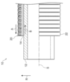
- a composite tube 10 according to this embodiment shown in FIG. 1 includes a tube body 12, a porous resin layer 14, and a coating layer 20.
- symbol S represents the axis
- the tubular body 12 is a resin tube that is tubular and is made of a resin material (that is, made of a resin material containing a resin).
- a resin material that is, made of a resin material containing a resin.
- the resin in the resin material for example, polyolefin such as polybutene, polyethylene, cross-linked polyethylene, and polypropylene, vinyl chloride, and the like are used, and the resin may be used alone or in combination of two or more.
- polybutene is preferably used, and preferably includes polybutene as a main component.
- the resin material constituting the tubular body may include 85% by mass or more.
- the resin material which comprises a tubular body may be the material which consists only of resin, but you may contain another additive.
- the covering layer 20 is tubular and covers the outer periphery of the tubular body 12 and the porous resin layer 14.
- the porous resin layer 14 is disposed between the tube body 12 and the coating layer 20.
- the coating layer is made of a resin material (that is, made of a resin material containing a resin).
- Polybutene, polyethylene, polypropylene, polyolefins such as cross-linked polyethylene, vinyl chloride, etc. are used as the resin in the resin material constituting the coating layer, and the resin may be used alone or in combination of two or more. .
- low-density polyethylene is preferably used, and preferably contains low-density polyethylene as a main component.
- the resin material constituting the coating layer preferably contains 80% by mass or more, and more preferably 90% by mass or more. Further preferred.
- MFR Melt Flow Rate
- the resin of the coating layer 20 can easily enter the porous structure of the porous resin layer 14, and the degree of adhesion between the porous resin layer 14 described later and the valley portion 24 of the coating layer 20. Can be increased.
- the resin material which comprises a coating layer may be the material which consists only of resin, you may contain another additive.
- the coating layer 20 has a bellows shape, and an annular peak portion 22 that protrudes radially outward, and an annular valley portion 24 that has a concave radially outer side,
- the tubular body 12 is formed alternately and continuously in the axial direction S.
- the mountain portion 22 is disposed outside the valley portion 24 in the radial direction R.
- the outermost wall 22A is the outermost wall portion of the accordion-like shape of the coating layer 20 and the inner wall 24A is the innermost portion in the radial direction
- the outer wall 22A and the inner wall 24A in the radial direction With the intermediate portion M as a boundary, the radially outer side is a mountain portion 22 and the radially inner side is a valley portion 24.
- the mountain portion 22 has an outer wall 22A extending in the axial direction S and a side wall 22B extending along the radial direction R from both ends of the outer wall 22A.
- An outer bent portion 22C is formed between the outer side wall 22A and the side wall 22B.
- the trough portion 24 has an inner wall 24A extending in the axial direction S and a side wall 24B extending in the radial direction R from both ends of the inner wall 24A.
- An inner bent portion 24C is formed between the inner side wall 24A and the side wall 24B.
- a concave mountain space 23 is formed on the radially inner side of the mountain portion 22 of the coating layer 20.
- the convex part 14B of the porous resin layer 14 mentioned later is inserted in the mountain space 23.
- the length L1 of the peak portion 22 in the axial direction S is preferably set to be longer than the length L2 of the valley portion 24 in the axial direction S.
- the length L1 is preferably 1.2 times or longer than the length L2 in order to secure the ease of deformation of the outer wall 22A during shortening deformation described later.
- the thickness of the coating layer 20 is preferably 0.1 mm or more at the thinnest portion and 0.4 mm or less at the thickest portion in order to shorten the coating layer 20.
- the thickness H1 of the outer side wall 22A is thinner than the thickness of the inner side wall 24A.
- the thickness H1 is preferably equal to or less than 0.9 times the thickness H2 in order to ensure ease of deformation of the outer wall 22A during shortening deformation described later.
- the radius difference ⁇ R between the outer surfaces of the peak portion 22 and the valley portion 24 is preferably 800% or less of the average thickness of the coating layer 20. If the radius difference ⁇ R is large, even if the portion along the axial direction S of the peak portion 22 is not deformed, the trough portion 24 does not bulge outward in the radial direction when shortening, and the adjacent peak portions 22 do not approach each other. It is difficult to become a distorted deformation state.
- the radius difference ⁇ R is 800% or less of the average thickness of the coating layer 20
- the length in the axial direction S of the peak portion 22 is set to the axis of the valley portion 24 in order to suppress the above-described deformation state. It is effective to make it longer than the length in the direction. It is more effective when the radius difference ⁇ R is 600% or less of the average thickness of the coating layer 20.
- a diameter (outermost outer diameter) of the coating layer 20 For example, it can be set as the range of 12.85 mm or more and 34.25 mm or less. In addition, the larger one is preferable from a viewpoint that the burr
- the porous resin layer 14 is made of a resin material (that is, made of a resin material containing a resin) and has a porous structure.
- a resin material that is, made of a resin material containing a resin
- polyurethane, polystyrene, polyethylene, polypropylene, ethylene propylene diene rubber, a mixture of these resins, and the like can be used, and among them, polyurethane is more preferable.
- a layer containing polyurethane as a main component is preferable.
- the constituent component of the porous resin layer preferably contains 80% by mass or more of polyurethane, more preferably 90% by mass or more.
- the resin material which comprises a porous resin layer may be a material which consists only of resin, you may contain another additive. It is preferable that the abundance ratio of the pores in the porous resin layer (for example, foaming rate in the case of a foam) is 25/25 mm or more and 45/25 mm or less. The abundance ratio of the holes can be measured by the method described in Appendix 1 of JIS-K6400-1 (2012).
- the porous resin layer 14 is disposed between the tube body 12 and the coating layer 20.
- the porous resin layer 14 is sandwiched while being compressed between the inner wall 24A of the valley portion 24 of the coating layer 20 and the tubular body 12, and a compression sandwiching portion 14A is formed.
- the porous resin layer 14, the repulsive force in the radial direction in the compression nip portion is in the 21N / cm 2 or more 30 N / cm 2 or less.
- the inner peripheral surface of the porous resin layer 14 is preferably flat, and preferably covers the outer periphery of the tubular body 12 while being in full contact with the outer periphery of the tubular body 12.
- “entire contact” means that all parts do not have to be in close contact with each other, but substantially the entire surface is in contact. Therefore, for example, when the porous resin layer 14 is formed by winding a sheet-shaped porous resin sheet, the joint portion is partially separated or wrinkled between the tube body 12 and the coating layer 20. This includes the case where the parts are partially separated.
- the shape of the porous resin layer can be a sheet, for example.
- the porous resin layer 14 is formed, for example, by coating a sheet-like porous resin sheet formed in a band shape so as to have a width substantially equal to the outer peripheral length of the tube body 12 around the tube body 12.
- the resin composition to be 20 can be produced by supplying it to the outer periphery and molding it.
- the thickness of the porous resin layer 14 is the radial direction of the outer periphery of the tubular body 12 and the inner wall 24A in a natural state (a state where a force such as compression or tension is not applied, a temperature of 23 ° C. and a relative humidity of 45%). It is more than the difference with the inner surface, and it is preferable that the thickness is further thicker than the difference.
- the porous resin layer 14 is thinner than the natural thickness due to compression.
- a convex portion 14B is formed between adjacent compression sandwiching portions 14A of the porous resin layer 14.
- the convex portion 14 ⁇ / b> B has a larger diameter than the compression sandwiching portion 14 ⁇ / b> A and protrudes into the mountain space 23.
- the top part (most radial direction outer side part) of the convex part 14B and 22 A of outer side walls are spaced apart.
- the compression sandwiching portions 14 ⁇ / b> A and the convex portions 14 ⁇ / b> B are alternately and continuously formed in the axial direction S, and the outer periphery of the porous resin layer 14 The surface is wavy.
- the thickness of the porous resin layer 14 in the natural state is 1.5 mm or more and 4.0 mm or less from the viewpoint of easy formation of the compression sandwiching portion 14A compressed by the inner wall 24A and the tube body 12.
- the range is preferably 2.0 mm or more and 3.0 mm or less.
- the thickness of the porous resin layer 14 in the natural state is an average value of values obtained by taking the porous resin layer 14 from the composite tube 10 and measuring 10 arbitrary locations.
- the length in the axial direction S in the natural state in which the porous resin layer 14 is extracted from between the tube body 12 and the covering layer 20 is 90% to 100% of the length in the axial direction S of the covering layer 20.
- the length in the axial direction S of the porous resin layer 14 in the natural state is 90% or more and 100% of the length in the axial direction of the coating layer 20. The following is preferable.
- the length L1 in the axial direction S is preferably longer than L2, and the thickness H1 is preferably thinner than H2. Accordingly, the outer wall 22A is more easily deformed than the inner wall 24A, and deforms so as to bulge outward in the radial direction as shown in FIG. Subsequently, as illustrated in FIG. 7, the outer bent portion 22 ⁇ / b> C of the peak portion 22 and the inner bent portion 24 ⁇ / b> C of the valley portion 24 are deformed so that the adjacent peak portions 22 approach each other. In this way, as shown in FIG. 5, the coating layer 20 at one end is more easily moved in the direction in which the tube body 12 is exposed.
- the outer wall 22A is deformed so as to bulge, so that even if the bending angle and thickness of the covering layer 20 have some variation, the trough portion 24 is radially outward. It is possible to suppress the bulging out and the deformation state that is distorted without the adjacent peak portions 22 being close to each other. Thereby, the fall of the external appearance of the shortened coating layer 20 can be suppressed.
- the repulsive force in the radial direction at the compression clamping portion of the porous resin layer 14 is 21 N / cm 2 or more. Therefore, when the end portion of the covering layer 20 is shortened and deformed to expose the end portion of the tubular body 12 and then the covering layer 20 is returned again, the porous resin layer 14 extends in the axial direction of the covering layer 20. Thus, the occurrence of a phenomenon in which a part of the entanglement is rounded into a damped shape is suppressed. Further, the porous resin layer 14 is compressed by the inner wall 24A and the tube body 12, the compression clamping portion 14A is in close contact with the coating layer 20, and the convex portion 14B is engaged between the side walls 24B of the adjacent valley portions 24. Therefore, it becomes easier to shorten together with the coating layer 20. Thereby, as shown in FIG. 8, the edge part of the tubular body 12 can be exposed.
- the thickness H1 of the outer wall 22A is made thinner than the thickness H2 of the inner wall 24A, but the thickness H1 may be the same as the thickness H2.
- the outer wall 22A has a substantially straight shape along the axial direction S, but may have an arc shape bulging outward in the radial direction. Further, the inner wall 24A may have an arc shape that bulges inward in the radial direction.
- another layer 13 may be provided between the porous resin layer 14 and the tube body 12.
- a low-friction sheet that improves slippage between the porous resin layer 14 and the tube body 12 is provided, and the end portion of the tube body 12 is exposed by shortening deformation of the coating layer 20, the porous resin layer 14 is exposed.
- the layer 14 and the other layer 13 may be easily deformed following the covering layer 20.
- the porous resin layer 14 is in full contact with the outer peripheral surface of the tube body 12.
- the tube body 12, the porous resin layer 14 and the coating layer 20 are relatively moved to expose the end of the tube body 12, and then the outer periphery of the tube body 12 and the inner periphery of the porous resin layer 14 are exposed.
- the porous resin layer 14 and the coating layer 20 can be easily held at the shortened position by the frictional force therebetween.
- the porous resin layer 14 is compressed by the inner wall 24A and the tube body 12, whereby the compression clamping portion 14A is in close contact with the coating layer 20, and the convex portion 14B is adjacent to the valley portion. Engage between the 24 side walls 24B. Therefore, the porous resin layer 14 is easily followed by the movement of the coating layer 20, and the porous resin layer 14 is suppressed from being left on the outer periphery of the tubular body 12, and can be easily shortened together with the coating layer 20. .
- a manufacturing apparatus 30 shown in FIG. 4 can be used for manufacturing the composite tube 10.
- the manufacturing apparatus 30 includes an extruder 32, a die 34, a corrugating mold 36, a cooling tank 38, and a take-up device 39.
- the right side of FIG. 4 is the upstream side, and the pipe body 12 is manufactured while moving from the right side to the left side.
- this moving direction is referred to as a manufacturing direction Y.
- the die 34, the corrugating mold 36, the cooling tank 38, and the take-up device 39 are arranged in this order with respect to the manufacturing direction Y, and the extruder 32 is arranged above the die 34.
- upstream of the die 34 is a tubular body 12 wound in a coil shape, and a sheet-like member 14S in which a porous resin sheet to be a porous resin layer 14 is wound in a roll shape.
- the coiled tubular body 12 and the roll-shaped sheet-like member 14 ⁇ / b> S are continuously pulled out by being pulled in the manufacturing direction Y by the pulling device 39.
- a sheet-like member 14S is wound around the entire outer periphery of the tubular body 12 drawn out continuously before the die 34. Note that the sheet-like member 14 ⁇ / b> S is inserted in the die 34 in a slack state before the die 34 in order not to apply a tensile force.
- a resin material (melt of the resin composition for forming the coating layer 20) melted from the die 34 is extruded and applied in a cylindrical shape, A resin layer 20A is formed.
- LDPE low density polyethylene
- the resin material can easily enter the pores (bubbles) of the porous resin sheet, and the sheet-like member 14S and the resin layer 20A Adhesion is improved.
- a corrugating process (formed in a bellows shape) is performed by a corrugating mold 36 disposed on the downstream side of the die 34.
- the corrugating dies 36 are, for example, two pairs of dies, each of which has a semicircular inner surface, and an annular cavity 36 ⁇ / b> A is formed at a portion corresponding to the peak portion 22 of the coating layer 20 on the inner periphery thereof. Is formed, and an annular inner protrusion 36B is formed at a portion corresponding to the valley 24, and has a bellows shape.
- Each cavity 36A is formed with a vent hole 36C having one end communicating with the cavity 36A and passing through the corrugating mold 36. In the cavity 36A, air is sucked from the outside of the corrugating mold 36 through the air hole 36C.
- the two pairs of corrugating dies 36 approach the resin layer 20A from two directions to contact the inner surfaces thereof, and press the resin layer 20A by the inner protrusions 36B while pressing the resin layer 20A.
- the outer periphery is covered and moved in the manufacturing direction Y together with the tubular body 12.
- air is sucked from the outside of the corrugating mold 36, and the inside of the cavity 36A is set to a negative pressure.
- the resin layer 20 ⁇ / b> A moves outward in the radial direction, and the bellows-like coating layer 20 along the corrugated mold 36 is formed.
- the repulsive force in the radial direction at the compression clamping portion of the porous resin layer 14 is 30 N / cm 2 or less. Therefore, the resin layer 20 ⁇ / b> A is pushed back from the porous resin layer 14 toward the radially outer side, and is prevented from being pushed out between the contact portions where the two pairs of corrugated dies 36 are in contact with each other. The burr
- the sheet-like member 14S enters the cavity 36A in the mountain space 23 corresponding to the mountain portion 22 of the coating layer 20, and the convex portion 14B is formed.
- a portion corresponding to the inner wall 24A of the valley portion 24 of the coating layer 20 is maintained in adhesion with the coating layer 20 and is compressed between the tubular body 12 and the inner wall 24A to form a compression sandwiching portion 14A. .
- the coating layer 20 is cooled in the cooling bath 38. In this way, the composite tube 10 is manufactured.
- a tubular tubular body made of a resin material, and an annular peak portion that is tubular and covers the outer periphery of the tubular body and protrudes radially outward.
- Resin that can be shortened in the axial direction while being guided by the outer periphery of the tubular body, with annular troughs that are concave on the radially outer side formed alternately in the axial direction of the tubular body A compression layer sandwiched between the valley portion and the tube, the compression layer sandwiched between the coating layer made of a material and the tube body and the coating layer; And a porous resin layer having a radial repulsion force of 21 N / cm 2 or more and 30 N / cm 2 or less.
- a composite pipe according to the first or second aspect in which the porous resin layer is a porous urethane layer.
- the composite pipe according to any one of the first to third aspects in which the density of the porous resin layer is 12 kg / m 3 or more and 22 kg / m 3 or less.
- a composite pipe according to any one of the first to fourth aspects in which a hysteresis loss of the porous resin layer is 42% or more.
- the porous resin layer has a sheet shape and is in full contact with the outer surface of the tubular body.
- a composite tube is provided.
- the axial length of the porous resin layer in a natural state is 90% or more and 100% or less of the axial length of the coating layer.
- a composite tube according to any one of the first to sixth aspects is provided.
- any one of the first to seventh aspects wherein a length of the peak portion in the axial direction is longer than a length of the valley portion in the axial direction.
- a composite tube is provided.
- urethane foam sheet (Production of urethane foam sheet A (2.5 mm)) Polyisocyanate and polyol as raw materials are mixed and reacted with a catalyst, a foaming agent and a foam stabilizer, and cut to a desired thickness with a cutting machine, and the thickness (average thickness in the natural state) is 2.5 mm.
- a urethane foam sheet A was prepared.
- urethane foam sheet B (3.0 mm)
- a urethane foam sheet B having a thickness (average thickness in a natural state) of 3.0 mm was produced by changing the thickness when cutting with a cutting machine.
- urethane foam sheet C (3.5 mm)
- a urethane foam sheet C having a thickness (average thickness in a natural state) of 3.5 mm was produced by changing the thickness when cutting with a cutting machine.
- urethane foam sheet D (5.0 mm)
- a urethane foam sheet D having a thickness (average thickness in a natural state) of 5.0 mm was produced by changing the thickness when cutting with a cutting machine.
- Example 1 (Production of composite tube) A manufacturing apparatus having the configuration shown in FIG. 4 was prepared. A polybutene tube wound up in a coil shape was attached as a tubular body 12, and the urethane foam sheet B (thickness: 3.0 mm) obtained above was attached as a sheet-like member 14S. The take-up device 39 was operated to continuously draw out the coiled polybutene tube and the roll-shaped urethane foam sheet B (sheet-like member 14S), and wound the urethane foam sheet B around the entire circumference of the polybutene tube. . The urethane foam sheet B was inserted into the die 34 with a slack before the die 34.
- a molten resin material (low density polyethylene (LDPE)) was extruded from the die 34 into a cylindrical shape on the outer periphery of the urethane foam sheet B, and a resin layer was formed.
- LDPE low density polyethylene
- the corrugated mold 36 is a pair of molds having the same inner surface shape, and both have a semicircular arc-shaped inner surface.
- An annular cavity 36A is formed at a portion corresponding to the peak portion of the coating layer to be formed on the inner periphery, and an annular inner protrusion 36B is formed at a portion corresponding to the valley portion, and has a bellows shape.
- Each cavity 36A is formed with a vent hole 36C having one end communicating with the cavity 36A and passing through the corrugating mold 36.
- the resin layer 20A is pressed by the inner protrusion 36B, the resin layer 20A is moved in the manufacturing direction Y together with the polybutene tube, and suction is performed from the outside of the corrugating mold 36, thereby making the inside of the cavity 36A negative pressure. . In this way, a bellows-like coating layer was formed along the corrugation mold 36. Subsequently, it cooled in the cooling tank 38 and the composite pipe
- the distance between the inner surface of the valley portion 24 of the coating layer and the outer surface of the polybutene tube (tube body), that is, the difference between the outer periphery of the tube body and the radially inner surface of the inner wall 24A of the coating layer (compression clamping portion clearance) is 2 0.0 mm.
- the length L1 in the axial direction S of the peak portion 22 of the coating layer was 2.1 mm
- the length L2 in the axial direction S of the valley portion 24 was 1.5 mm.
- the thickness of the coating layer was 0.2 mm at the thinnest part and 0.5 mm at the thickest part.
- the radius difference ⁇ R between the outer surfaces of the peak portion 22 and the valley portion 24 was 88.9%.
- the diameter of the coating layer (outermost outer diameter) was 23.5 mm.
- the urethane foam sheet B layer was in full contact with the outer surface of the tubular body.
- Examples 2 to 3, Comparative Examples 1 to 3 The urethane foam sheet used is changed to the one shown in Table 1 below, and the distance between the inner surface of the valley portion 24 of the coating layer and the outer surface of the polybutene tube (tube body) is adjusted by adjusting the diameter of the coating layer. ) was adjusted to the values shown in Table 1 below, and a composite tube was obtained in the same manner as in Example 1.
Landscapes
- Engineering & Computer Science (AREA)
- General Engineering & Computer Science (AREA)
- Mechanical Engineering (AREA)
- Rigid Pipes And Flexible Pipes (AREA)
- Laminated Bodies (AREA)
Abstract
樹脂材料で構成される管状の管体と、管状とされて管体の外周を覆い、径方向外側へ凸となる環状の山部と、径方向外側が凹となる環状の谷部とが、管体の軸方向に交互に形成されて蛇腹状とされ、管体の外周にガイドされつつ軸方向に短縮可能な、樹脂材料で構成される被覆層と、管体と被覆層との間に配置され、谷部と管体との間に圧縮されつつ挟持された圧縮挟持部を有し、圧縮挟持部での径方向への反発力が21N/cm2以上30N/cm2以下である多孔質樹脂層と、を有する複合管。
Description
本開示は、複層構造の複合管に関する。
従来から、配管を保護するために、配管を覆う種々の管が提案されている。例えば、特許文献1には、内部に配線又は配管材が挿通される波付管であって、少なくとも内面側が、フッ素樹脂を混入した、ポリオレフィン系合成樹脂または塩化ビニル樹脂により成形されてなる、配線・配管材用の波付管が開示されている。
[特許文献1] 特開2015-48909号公報
ところで、内部の管体と、この管体の外周を覆う蛇腹状の被覆層と、を有する複合管において、さらに緩衝性を高める観点で管体と被覆層との間に緩衝層としての多孔質樹脂層を配置することが考えられる。なお、こうした複合管では、内部の管体の端部に継手などを接続するときに、被覆層をずらしたりして管体端部を露出させることが求められる。また、管体の端部を継手などに接続した後、被覆層を元に戻して再び管体を被覆することが求められる。
しかし、管体を露出させた後に再び被覆層を元に戻すとき、多孔質樹脂層には、元に戻ろうとして軸方向に移動する外周側の被覆層と、内周側の管体とから、それぞれ逆方向の摩擦力が与えられる。そのため、被覆層の移動に対し多孔質樹脂層が追従せず、外周側及び内周側からそれぞれ加えられる逆方向の摩擦力によって、多孔質樹脂層に巻き込まれが発生して、一部がダマ状に丸め込まれる現象が生じることがある。なお、この巻き込まれが発生すると、多孔質樹脂層が元の位置まで戻らないことがある。
しかし、管体を露出させた後に再び被覆層を元に戻すとき、多孔質樹脂層には、元に戻ろうとして軸方向に移動する外周側の被覆層と、内周側の管体とから、それぞれ逆方向の摩擦力が与えられる。そのため、被覆層の移動に対し多孔質樹脂層が追従せず、外周側及び内周側からそれぞれ加えられる逆方向の摩擦力によって、多孔質樹脂層に巻き込まれが発生して、一部がダマ状に丸め込まれる現象が生じることがある。なお、この巻き込まれが発生すると、多孔質樹脂層が元の位置まで戻らないことがある。
また、管体と、管体を覆う蛇腹状の被覆層と、管体及び被覆層の間に配置された多孔質樹脂層とを有する複合管の作製は、例えば、管体の外周上に多孔質樹脂層となるシートを巻き付けた状態で、さらに多孔質樹脂層の外周上に被覆層形成用の樹脂組成物の溶融物を塗布し、この溶融物を蛇腹状に形成しつつ固化させることで行われる。このとき、被覆層形成用の樹脂組成物の溶融物を蛇腹状に形成するため、半円弧状の内面を有しかつこの内面が蛇腹の形状を有する二対の金型を、前記溶融物の外周面に対して二方向から接近させて接触させ、固化させることで蛇腹状に形成する方法が考えられる。
しかし、多孔質樹脂層の外周上に塗布された前記溶融物に対し、多孔質樹脂層から径方向外側に向かって押し返されるように力が加わるため、二対の金型の内面内に溶融物が収まり切らず、本来溶融物が進入しないはずの二対の金型の接触部にまで溶融物が押し出されることがある。その結果、固化された被覆層の外側にバリが生じることがある。被覆層が外側にバリを有すると、管体端部を露出させる為にずらそうとする動作の障害となり、被覆層自体を短縮させることが難しくなる。また、外側に発生したバリを除去する工程を設けることも考えられるが、この除去工程により複合管の製造が煩雑となる。
しかし、多孔質樹脂層の外周上に塗布された前記溶融物に対し、多孔質樹脂層から径方向外側に向かって押し返されるように力が加わるため、二対の金型の内面内に溶融物が収まり切らず、本来溶融物が進入しないはずの二対の金型の接触部にまで溶融物が押し出されることがある。その結果、固化された被覆層の外側にバリが生じることがある。被覆層が外側にバリを有すると、管体端部を露出させる為にずらそうとする動作の障害となり、被覆層自体を短縮させることが難しくなる。また、外側に発生したバリを除去する工程を設けることも考えられるが、この除去工程により複合管の製造が煩雑となる。
本開示は、係る事実を考慮し、管状の管体と、管状とされて管体の外周を覆う被覆層と、管体と被覆層との間に配置される多孔質樹脂層と、を有する態様において、被覆層の径方向外側におけるバリが抑制され、かつ被覆層の端部を短縮変形させて管体の端部を露出させた後さらに短縮させた被覆層を伸長して元に戻す際における多孔質樹脂層の巻き込まれ(丸め込まれ)の発生が抑制された複合管を提供することを課題とする。
前記課題は、以下の本開示により解決される。
<1> 樹脂材料で構成される管状の管体と、管状とされて前記管体の外周を覆い、径方向外側へ凸となる環状の山部と、径方向外側が凹となる環状の谷部とが、前記管体の軸方向に交互に形成されて蛇腹状とされ、前記管体の外周にガイドされつつ前記軸方向に短縮可能な、樹脂材料で構成される被覆層と、前記管体と前記被覆層との間に配置され、前記谷部と前記管体との間に圧縮されつつ挟持された圧縮挟持部を有し、前記圧縮挟持部での径方向への反発力が21N/cm2以上30N/cm2以下である多孔質樹脂層と、を有する複合管である。
本開示によれば、管状の管体と、管状とされて管体の外周を覆う被覆層と、管体と被覆層との間に配置される多孔質樹脂層と、を有する態様において、被覆層の径方向外側におけるバリが抑制され、かつ被覆層の端部を短縮変形させて管体の端部を露出させた後さらに短縮させた被覆層を伸長して元に戻す際における多孔質樹脂層の巻き込まれ(丸め込まれ)の発生が抑制された複合管を提供することができる。
以下、本開示に係る複合管の一例である実施形態について、図面を適宜参照しながら詳細に説明する。各図面において同一の符号を用いて示される構成要素は、同一の構成要素であることを意味する。なお、以下に説明する実施形態において重複する説明及び符号については、省略する場合がある。
なお、本明細書において、「主成分」とは、特に断りがない限り、混合物中における質量基準の含有量が最も多い成分をいう。
なお、本明細書において、「主成分」とは、特に断りがない限り、混合物中における質量基準の含有量が最も多い成分をいう。
<複合管>
本開示に係る複合管は、管状の管体と、管状とされて管体の外周を覆う被覆層と、管体と被覆層との間に配置される多孔質樹脂層と、を有する。
管体は、樹脂材料で構成され、つまり樹脂を含む樹脂材料からなる。
被覆層は、樹脂材料で構成され、つまり樹脂を含む樹脂材料からなる。また、その形状は、径方向外側へ凸となる環状の山部と、径方向外側が凹となる環状の谷部とが、管体の軸方向に交互に形成されて蛇腹状とされ、管体の外周にガイドされつつ軸方向に短縮可能とされる。
多孔質樹脂層は、前記谷部と管体との間に圧縮されつつ挟持された圧縮挟持部を有し、この圧縮挟持部での径方向への反発力が21N/cm2以上30N/cm2以下である。
・圧縮挟持部の反発力
複合管では、内部の管体の端部に継手などを接続するときに、被覆層の端部を短縮させてずらして管体端部を露出させ、また管体の端部を継手などに接続した後に短縮させた被覆層を伸長して元に戻し、再び管体を被覆することが求められる。しかし、図10に示すように、管体12を露出させた後に再び被覆層20を元に戻すとき、被覆層20は元に戻ろうとして軸方向に移動するため、多孔質樹脂層14には被覆層20から矢印A方向に働く力が与えられ、一方管体12は被覆層20の軸方向への移動に対して相対的にその場に留まろうとするため、多孔質樹脂層14には管体12から矢印B方向に働く力が与えられる。つまり、多孔質樹脂層14には被覆層20(外周側)及び管体12(内周側)からそれぞれ逆方向の摩擦力が与えられる。そのため、被覆層20の移動に対し多孔質樹脂層14が追従し切らないと、外周側及び内周側からそれぞれ加えられる逆方向の摩擦力によって、多孔質樹脂層14に巻き込まれが発生して、一部がダマ状に丸め込まれる現象が生じることがある。ここで、多孔質樹脂層14に巻き込まれが発生して一部がダマ状に丸め込まれた箇所を示す斜視図を、図11に示す。図11に示す複合管では、多孔質樹脂層14の端部に巻き込まれCが発生している。なお、この巻き込まれCの発生箇所を示す図では、被覆層20を再度短縮させて巻き込まれCの発生箇所を露出させた状態を示している。また、図11には多孔質樹脂層14の端部に巻き込まれCが発生した状態を示しているが、多孔質樹脂層14の端部ではなく、軸方向の中央側(軸方向の途中)に巻き込まれ(丸め込まれ)が生じることもある。
複合管では、内部の管体の端部に継手などを接続するときに、被覆層の端部を短縮させてずらして管体端部を露出させ、また管体の端部を継手などに接続した後に短縮させた被覆層を伸長して元に戻し、再び管体を被覆することが求められる。しかし、図10に示すように、管体12を露出させた後に再び被覆層20を元に戻すとき、被覆層20は元に戻ろうとして軸方向に移動するため、多孔質樹脂層14には被覆層20から矢印A方向に働く力が与えられ、一方管体12は被覆層20の軸方向への移動に対して相対的にその場に留まろうとするため、多孔質樹脂層14には管体12から矢印B方向に働く力が与えられる。つまり、多孔質樹脂層14には被覆層20(外周側)及び管体12(内周側)からそれぞれ逆方向の摩擦力が与えられる。そのため、被覆層20の移動に対し多孔質樹脂層14が追従し切らないと、外周側及び内周側からそれぞれ加えられる逆方向の摩擦力によって、多孔質樹脂層14に巻き込まれが発生して、一部がダマ状に丸め込まれる現象が生じることがある。ここで、多孔質樹脂層14に巻き込まれが発生して一部がダマ状に丸め込まれた箇所を示す斜視図を、図11に示す。図11に示す複合管では、多孔質樹脂層14の端部に巻き込まれCが発生している。なお、この巻き込まれCの発生箇所を示す図では、被覆層20を再度短縮させて巻き込まれCの発生箇所を露出させた状態を示している。また、図11には多孔質樹脂層14の端部に巻き込まれCが発生した状態を示しているが、多孔質樹脂層14の端部ではなく、軸方向の中央側(軸方向の途中)に巻き込まれ(丸め込まれ)が生じることもある。
これに対し本開示では、多孔質樹脂層の圧縮挟持部での径方向への反発力が21N/cm2以上である。
これにより、多孔質樹脂層14が管体12側に押し付けられ過ぎず、被覆層20の端部を短縮変形させて管体12の端部を露出させた後に再び被覆層20を元に戻す際に、多孔質樹脂層14が被覆層20の軸方向への伸長の動作に対して良好に追従し、巻き込まれによる一部がダマ状に丸め込まれる現象の発生が抑制される。その結果、露出された管体12の端部を再び多孔質樹脂層14及び被覆層20によって良好に覆うことができる。
これにより、多孔質樹脂層14が管体12側に押し付けられ過ぎず、被覆層20の端部を短縮変形させて管体12の端部を露出させた後に再び被覆層20を元に戻す際に、多孔質樹脂層14が被覆層20の軸方向への伸長の動作に対して良好に追従し、巻き込まれによる一部がダマ状に丸め込まれる現象の発生が抑制される。その結果、露出された管体12の端部を再び多孔質樹脂層14及び被覆層20によって良好に覆うことができる。
なお、圧縮挟持部での径方向への反発力の下限値は、巻き込まれ(丸め込まれ)発生の抑制の観点から、22N/cm2以上が好ましい。
また、複合管を作製する際、例えば、管体の外周上に多孔質樹脂層となるシートを巻き付けた状態で、さらに被覆層形成用の樹脂組成物の溶融物を塗布し、この溶融物の外周面に対して、半円弧状の内面を有しかつこの内面が蛇腹の形状を有する二対の金型を二方向から接近させて接触させ、固化させることで蛇腹状に形成する方法が考えられる。しかし、塗布された溶融物には多孔質樹脂層から径方向外側に向かって押し返されるように力が加わるため、二対の金型の接触部に溶融物が押し出されて、被覆層の外側にバリが生じることがある。
これに対し本開示では、多孔質樹脂層の圧縮挟持部での径方向への反発力が30N/cm2以下である。
これにより、塗布された溶融物に対して多孔質樹脂層から加えられる径方向外側に向かう押し返しの力が制限され、被覆層形成用の樹脂組成物の溶融物が多孔質樹脂層から径方向外側に向かって押し返されて、二対の金型の接触部に押し出されることが抑制され、被覆層の径方向外側におけるバリが抑制される。そのため、管体端部を露出させる為に被覆層を短縮させてずらそうとする動作に対し、バリが障害となることが抑制され、被覆層の短縮の動作が容易に行える。また、被覆層の径方向外側に発生したバリを除去する工程が省略され、複合管の製造が煩雑となることが抑制される。
なお、圧縮挟持部での径方向への反発力の上限値は、バリの抑制の観点から、25N/cm2以下が好ましい。
圧縮挟持部での径方向への反発力の範囲は、21N/cm2以上30N/cm2以下であり、22N/cm2以上28N/cm2以下がより好ましく、22N/cm2以上25N/cm2以下がさらに好ましい。
圧縮挟持部での径方向への反発力の範囲は、21N/cm2以上30N/cm2以下であり、22N/cm2以上28N/cm2以下がより好ましく、22N/cm2以上25N/cm2以下がさらに好ましい。
ここで、多孔質樹脂層の圧縮挟持部での径方向への反発力は、JIS-K6400-2(2012年)に規定の「6.8 E法(圧縮たわみ係数及びヒステリシスロス率を求める方法)」において作成される「力-たわみ曲線」から求めることができる。なお、測定環境は温度23℃、相対湿度45%の環境とする。また、力-たわみ曲線の測定は計3回を行い、その内の2回目の結果を採用する。
多孔質樹脂層の圧縮挟持部での径方向への反発力を上記の範囲に制御する方法としては、特に限定されるものではないが、例えば多孔質樹脂層の圧縮挟持部での圧縮率を調整する方法、多孔質樹脂層の弾性率を調整する方法(例えば多孔質樹脂層における孔の存在比率(例えば発泡体である場合であれば発泡率)を調整したり、多孔質樹脂の分子構造を調整する(つまり多孔質樹脂の原料となるモノマーの分子構造や、それらの架橋構造を調整する)方法)等が挙げられる。
・圧縮率
多孔質樹脂層の圧縮挟持部での径方向への反発力を上記の範囲に制御する観点で、多孔質樹脂層の圧縮挟持部での圧縮率は、160%以上230%以下が好ましく、165%以上220%以下がより好ましく、170%以上200%以下がさらに好ましい。
い。
なお、圧縮率とは、「多孔質樹脂層の自然状態(圧縮や引っ張りなどの力が作用していない、温度23℃、相対湿度45%の状態)での厚さB/多孔質樹脂層の圧縮挟持部での厚さA」の値を表す。
多孔質樹脂層の圧縮挟持部での径方向への反発力を上記の範囲に制御する観点で、多孔質樹脂層の圧縮挟持部での圧縮率は、160%以上230%以下が好ましく、165%以上220%以下がより好ましく、170%以上200%以下がさらに好ましい。
い。
なお、圧縮率とは、「多孔質樹脂層の自然状態(圧縮や引っ張りなどの力が作用していない、温度23℃、相対湿度45%の状態)での厚さB/多孔質樹脂層の圧縮挟持部での厚さA」の値を表す。
圧縮挟持部での圧縮率は、自然状態での多孔質樹脂層の厚さ、及び管体の外周と被覆層の谷部の内側壁の径方向内側面との差(距離)により、調整し得る。
・多孔質ウレタン層
多孔質樹脂層は、樹脂材料で構成され(つまり樹脂を含む樹脂材料からなり)多孔質構造を有する層である。なお、多孔質樹脂層を構成する樹脂材料における樹脂は、特に限定されるものではないが、中でもポリウレタンが好ましく、ポリウレタンを主成分として含む多孔質ウレタン層であることが好ましい。
多孔質樹脂層を構成する樹脂材料は樹脂のみからなる材料であってもよいが、他の添加剤を含有してもよい。
多孔質樹脂層は、樹脂材料で構成され(つまり樹脂を含む樹脂材料からなり)多孔質構造を有する層である。なお、多孔質樹脂層を構成する樹脂材料における樹脂は、特に限定されるものではないが、中でもポリウレタンが好ましく、ポリウレタンを主成分として含む多孔質ウレタン層であることが好ましい。
多孔質樹脂層を構成する樹脂材料は樹脂のみからなる材料であってもよいが、他の添加剤を含有してもよい。
・多孔質樹脂層の密度
本開示に係る複合管では、多孔質樹脂層の密度が12kg/m3以上22kg/m3以下であることが好ましい。さらには、14kg/m3以上20kg/m3以下の範囲がより好ましい。
本開示に係る複合管では、多孔質樹脂層の密度が12kg/m3以上22kg/m3以下であることが好ましい。さらには、14kg/m3以上20kg/m3以下の範囲がより好ましい。
複合管では、内部の管体の端部に継手などを接続するときに、被覆層の端部を短縮させてずらし、管体端部を露出させることが求められる。しかし、被覆層をずらすときに多孔質樹脂層が追従せず、管体の外表面に置き去りになって、管体が十分に露出できないことがある。これに対し、多孔質樹脂層の密度が22kg/m3以下であることで、多孔質樹脂層が適度な柔軟性を有し、被覆層の端部を短縮変形させて管体の端部を露出させる際に、多孔質樹脂層が被覆層の動作に対して良好に追従し、管体の外表面へ置き去りとなることが抑制される。その結果、管体の端部の露出を容易に行うことができる。
一方、多孔質樹脂層は、密度が12kg/m3以上であることで適度な強度を有し、複合管の製造時等の加工時における多孔質樹脂層の破れ及び破損の発生が抑制される。
一方、多孔質樹脂層は、密度が12kg/m3以上であることで適度な強度を有し、複合管の製造時等の加工時における多孔質樹脂層の破れ及び破損の発生が抑制される。
ここで、多孔質樹脂層の密度は、JIS-K7222(2005年)に規定の方法により測定することができる。なお、測定環境は温度23℃、相対湿度45%の環境とする。
多孔質樹脂層の密度を上記の範囲に制御する方法としては、特に限定されるものではないが、例えば多孔質樹脂層における孔の存在比率(例えば発泡体である場合であれば発泡率)を調整する方法、樹脂の分子構造を調整する(つまり樹脂の原料となるモノマーの分子構造や、それらの架橋構造を調整する)方法等が挙げられる。
・多孔質樹脂層のヒステリシスロス
本開示に係る複合管では、多孔質樹脂層のヒステリシスロスが42%以上であることが好ましい。なお、ヒステリシスロスの上限値は、特に限定されるものではないが、80%以下が好ましい。
本開示に係る複合管では、多孔質樹脂層のヒステリシスロスが42%以上であることが好ましい。なお、ヒステリシスロスの上限値は、特に限定されるものではないが、80%以下が好ましい。
複合管を作製する際、例えば、管体の外周上に多孔質樹脂層となるシートを巻き付けた状態で、さらに被覆層形成用の樹脂組成物の溶融物を塗布し、この溶融物の外周面に対して、半円弧状の内面を有しかつこの内面が蛇腹の形状を有する二対の金型を二方向から接近させて接触させ、固化させることで蛇腹状に形成する方法が考えられる。しかし、塗布された溶融物には多孔質樹脂層から径方向外側に向かって押し返されるように力が加わるため、二対の金型の接触部に溶融物が押し出されて、被覆層の外側にバリが生じることがある。これに対し、多孔質樹脂層のヒステリシスロスが42%以上であることで、多孔質樹脂層のヘタリ性が適度な範囲に調整され、被覆層形成用の樹脂組成物の溶融物が多孔質樹脂層から径方向外側に向かって押し返されて、二対の金型の接触部に押し出されることが抑制され、被覆層の径方向外側におけるバリが抑制される。そのため、管体端部を露出させる為に被覆層を短縮させてずらそうとする動作に対し、バリが障害となることが抑制され、被覆層の短縮の動作が容易に行える。また、被覆層の径方向外側に発生したバリを除去する工程が省略され、複合管の製造が煩雑となることが抑制される。
ここで、多孔質樹脂層のヒステリシスロスは、JIS-K6400-2(2012年)に規定の方法により測定することができる。なお、測定環境は温度23℃、相対湿度45%の環境とする。また、ヒステリシスロスは計3回測定を行い、その内の2回目の結果を採用する。
多孔質樹脂層のヒステリシスロスを上記の範囲に制御する方法としては、特に限定されるものではないが、例えば多孔質樹脂層における孔の存在比率(例えば発泡体である場合であれば発泡率)を調整する方法、樹脂の分子構造を調整する(つまり樹脂の原料となるモノマーの分子構造や、それらの架橋構造を調整する)方法等が挙げられる。
次いで、本開示の複合管を実施するための形態を、一例を挙げ図面に基づき説明する。
図1に示される本実施形態に係る複合管10は、管体12、多孔質樹脂層14、及び被覆層20、を備えている。なお、符号Sは管体12の軸、及びその軸方向を表す。
(管体)
管体12は、管状とされ、樹脂材料で構成される(つまり樹脂を含む樹脂材料からなる)樹脂管である。
樹脂材料における樹脂には、例えばポリブテン、ポリエチレン、架橋ポリエチレン、及びポリプロピレン等のポリオレフィン、塩化ビニル等が用いられ、樹脂は1種のみを用いても2種以上を併用してもよい。中でも、ポリブテンが好適に用いられ、ポリブテンを主成分として含むことが好ましく、例えば管体を構成する樹脂材料中において85質量%以上含む態様とすることができる。
また、管体を構成する樹脂材料は樹脂のみからなる材料であってもよいが、他の添加剤を含有してもよい。
管体12は、管状とされ、樹脂材料で構成される(つまり樹脂を含む樹脂材料からなる)樹脂管である。
樹脂材料における樹脂には、例えばポリブテン、ポリエチレン、架橋ポリエチレン、及びポリプロピレン等のポリオレフィン、塩化ビニル等が用いられ、樹脂は1種のみを用いても2種以上を併用してもよい。中でも、ポリブテンが好適に用いられ、ポリブテンを主成分として含むことが好ましく、例えば管体を構成する樹脂材料中において85質量%以上含む態様とすることができる。
また、管体を構成する樹脂材料は樹脂のみからなる材料であってもよいが、他の添加剤を含有してもよい。
(被覆層)
被覆層20は、管状とされ、管体12及び多孔質樹脂層14の外周を覆っている。多孔質樹脂層14は、管体12と被覆層20の間に配置されている。
被覆層は、樹脂材料で構成される(つまり樹脂を含む樹脂材料からなる)。被覆層を構成する樹脂材料における樹脂には、ポリブテン、ポリエチレン、ポリプロピレン、及び架橋ポリエチレン等のポリオレフィン、塩化ビニル等が用いられ、樹脂は1種のみを用いても2種以上を併用してもよい。中でも、低密度ポリエチレンが好適に用いられ、低密度ポリエチレンを主成分として含むことが好ましく、例えば被覆層を構成する樹脂材料中において80質量%以上含むことがより好ましく、90質量%以上含むことがさらに好ましい。
また、使用する樹脂のMFR(Melt Flaw Rate)は、0.4以上であることが好ましい。MFRを0.4以上にすることにより、多孔質樹脂層14の多孔質構造に被覆層20の樹脂が入り込みやすくなり、後述する多孔質樹脂層14と被覆層20の谷部24との接着度を高めることができる。
なお、被覆層を構成する樹脂材料は樹脂のみからなる材料であってもよいが、他の添加剤を含有してもよい。
図2にも示されるように、被覆層20は、蛇腹状とされており、径方向外側へ凸となる環状の山部22と、径方向外側が凹となる環状の谷部24とが、管体12の軸方向Sに交互に連続して形成されている。山部22は、谷部24よりも径方向Rの外側に配置されている。図3に示されるように、被覆層20の蛇腹状の最も径方向外側の部分を外側壁22A、最も径方向内側の部分を内側壁24Aとすると、径方向における外側壁22Aと内側壁24Aの中間部Mを境界として、径方向外側を山部22とし、径方向内側を谷部24とする。
山部22は、軸方向Sに延びる外側壁22Aと、外側壁22Aの両端から径方向Rに沿って延びる側壁22Bを有している。外側壁22Aと側壁22Bの間には、外屈曲部22Cが形成されている。谷部24は、軸方向Sに延びる内側壁24Aと、内側壁24Aの両端から径方向Rに延びる側壁24Bを有している。内側壁24Aと側壁24Bの間には、内屈曲部24Cが形成されている。
被覆層20の山部22の径方向内側には、径方向内側に凹の山空間23が形成されている。なお、山空間23には、後述する多孔質樹脂層14の凸部14Bが挿入されていることが好ましい。
また、特に限定されるものではないが、山部22の軸方向Sの長さL1は、谷部24の軸方向Sの長さL2よりも長く設定されていることが好ましい。長さL1は、後述する短縮変形時の外側壁22Aの変形しやすさを確保するため、長さL2の1.2倍以上であることが好ましい。また、長さL1は、長さL2の5倍以下であることが好ましい。長さL1を長さL2の5倍以下にすることにより、複合官10の可撓性を保つことができる。また、長さL1が長すぎると、複合管10を敷設する際に、地面との接触面積が大きくなって施工しにくくなるためである。
被覆層20の厚みは、被覆層20を短縮させるために、最も薄い部分で0.1mm以上、最も厚い部分で0.4mm以下であることが好ましい。外側壁22Aの厚みH1は、内側壁24Aの厚みよりも薄くなっている。厚みH1は、後述する短縮変形時の外側壁22Aの変形しやすさを確保するため、厚みH2の0.9倍以下であることが好ましい。
山部22と谷部24の外表面での半径差ΔRは、被覆層20の厚みの平均の800%以下であることが好ましい。半径差ΔRが大きければ、山部22の軸方向Sに沿った部分が変形しなくても、短縮のときに谷部24が径方向外側へ膨出したり、隣り合う山部22同士が近づかないで歪んだ変形状態となったりしにくい。半径差ΔRが、被覆層20の厚みの平均の800%以下となる場合に、上記の変形状態となることを抑制するために、山部22の軸方向Sの長さを谷部24の軸方向の長さよりも長くすることが、効果的である。なお、半径差ΔRが、被覆層20の厚みの平均の600%以下である場合に、より効果的である。
被覆層20の径(最外部の外径)としては、特に限定されるものではないが、例えば12.85mm以上34.25mm以下の範囲とすることができる。なお、被覆層20の径方向外側におけるバリを抑制し易いとの観点からは、径は大きい方が好ましい。
(多孔質樹脂層)
多孔質樹脂層14は、樹脂材料で構成され(つまり樹脂を含む樹脂材料からなり)、多孔質構造を有する。多孔質樹脂層を構成する樹脂材料における樹脂には、ポリウレタン、ポリスチレン、ポリエチレン、ポリプロピレン、エチレンプロピレンジエンゴム、及びこれらの樹脂の混合物等を用いることができ、中でもポリウレタンがより好ましい。ポリウレタンを主成分として含む層であることが好ましく、例えば、多孔質樹脂層の構成成分中においてポリウレタンを80質量%以上含むことが好ましく、90質量%以上含むことがより好ましい。なお、多孔質樹脂層を構成する樹脂材料は樹脂のみからなる材料であってもよいが、他の添加剤を含有してもよい。
多孔質樹脂層における孔の存在比率(例えば発泡体の場合であれば発泡率)は、25個/25mm以上45個/25mm以下であることが好ましい。なお、上記孔の存在比率は、JIS-K6400-1(2012年)の付属書1に記載の方法により測定することができる。
多孔質樹脂層14は、管体12と被覆層20との間に配置されている。多孔質樹脂層14は、被覆層20の谷部24の内側壁24Aと管体12との間に圧縮されつつ挟持されており、圧縮挟持部14Aが形成されている。
そして、多孔質樹脂層14は、この圧縮挟持部での径方向への反発力が21N/cm2以上30N/cm2以下となっている。
多孔質樹脂層14の内周面は平坦状とされていることが好ましく、さらに管体12の外周に全面的に接触しつつ、管体12の外周を覆っていることが好ましい。なお、ここでの「全面的に接触」とは、全ての部分がぴったりと密着している必要はなく、実質的に全面が接触していることを意味する。したがって、例えば多孔質樹脂層14がシート形状の多孔質樹脂シートを巻き付けて形成されている場合、その継ぎ目部分が一部離間していたり、管体12と被覆層20との間でシワになった部分が一部離間していたりする場合を含んでいる。
多孔質樹脂層は、例えばその形状をシート状とすることができる。多孔質樹脂層14は、例えば、管体12の外周長と略等しい長さの幅を有するように帯状に形成されたシート状の多孔質樹脂シートを管体12の周囲に巻き付けながら、被覆層20となる樹脂組成物をその外周に供給して成形することにより、作製することができる。
多孔質樹脂層14の厚さは、自然状態(圧縮や引っ張りなどの力が作用していない、温度23℃、相対湿度45%の状態)で、管体12の外周と内側壁24Aの径方向内側面との差以上となっており、さらに前記差よりも厚くなっていることが好ましい。
圧縮挟持部14Aでは、圧縮により、多孔質樹脂層14は、自然状態の厚みより薄くなっている。多孔質樹脂層14の隣り合う圧縮挟持部14A同士の間には、凸部14Bが形成されている。凸部14Bは、圧縮挟持部14Aよりも大径とされ、山空間23内へ突出している。なお、山空間23内において、凸部14Bの頂部(最も径方向外側部分)と外側壁22Aとは離間していることが好ましい。多孔質樹脂層14が内側壁24Aと管体12とで圧縮されている場合、圧縮挟持部14Aと凸部14Bとが軸方向Sに交互に連続して形成され、多孔質樹脂層14の外周面が波状となっている。
なお、多孔質樹脂層14の自然状態での厚さは、内側壁24Aと管体12とで圧縮された圧縮挟持部14Aの形成のし易さの観点から、1.5mm以上4.0mm以下の範囲が好ましく、2.0mm以上3.0mm以下がより好ましい。なお、多孔質樹脂層14の自然状態での厚さは、複合管10から多孔質樹脂層14を取り出して、任意の箇所10箇所を測定して得られた値の平均値とする。
多孔質樹脂層14を管体12と被覆層20の間から抜き出した自然状態における軸方向Sの長さは、被覆層20の軸方向Sの長さの90%以上100%以下であることが好ましい。これは、多孔質樹脂層14が管体12と被覆層20の間において伸張状態で保持されていると、被覆層20を短縮変形させる際に、多孔質樹脂層14と被覆層20との相対移動が生じやすくなり、多孔質樹脂層14が短縮されずに管体12の外周端部を露出できないことが生じうるからである。多孔質樹脂層14と被覆層20との相対移動を抑制するため、自然状態における多孔質樹脂層14の軸方向Sの長さは、被覆層20の軸方向の長さの90%以上100%以下とすることが好ましい。
次に、本実施形態の複合管10の作用について説明する。
本実施形態に係る複合管10と継手とを接続する際には、図2に示す状態の被覆層20に対し、被覆層20を軸方向Sに短縮させて管体12を露出させる方向の力を作用させる。これにより、図5に示されるように、一端部の被覆層20は、管体12が露出される方向へ移動する。
なお、山部22の外側壁22Aと谷部24の内側壁24Aにおいて、軸方向Sの長さL1はL2よりも長く、厚みH1はH2よりも薄いことが好ましい。これにより、外側壁22Aは内側壁24Aよりも変形しやすく、図6に示されるように、径方向外側へ膨出するように変形する。続いて、図7に示されるように、隣り合う山部22同士が近づくように、山部22の外屈曲部22Cと谷部24の内屈曲部24Cが変形する。このようにして、図5に示されるように、一端部の被覆層20は、管体12が露出される方向へより移動し易くなる。このように、被覆層20を短縮させる際に、外側壁22Aが膨出するように変形するため、被覆層20の屈曲角度や厚みに多少のバラツキがあっても、谷部24が径方向外側へ膨出したり、隣り合う山部22同士が近づかないで歪んだ変形状態となったりすることを抑制できる。これにより、短縮させた被覆層20の外観の低下を抑制することができる。
ここで、本実施形態では、多孔質樹脂層14の圧縮挟持部での径方向への反発力が21N/cm2以上である。そのため、被覆層20の端部を短縮変形させて管体12の端部を露出させた後に再び被覆層20を元に戻す際に、多孔質樹脂層14が被覆層20の軸方向への伸長の動作に対して良好に追従し、巻き込まれによる一部がダマ状に丸め込まれる現象の発生が抑制される。
また、多孔質樹脂層14は内側壁24Aと管体12とで圧縮されており、圧縮挟持部14Aが被覆層20に密着され、凸部14Bが隣り合う谷部24の側壁24Bの間に係合し、被覆層20と共により短縮し易くなる。これにより、図8に示すように、管体12の端部を露出させることができる。
また、多孔質樹脂層14は内側壁24Aと管体12とで圧縮されており、圧縮挟持部14Aが被覆層20に密着され、凸部14Bが隣り合う谷部24の側壁24Bの間に係合し、被覆層20と共により短縮し易くなる。これにより、図8に示すように、管体12の端部を露出させることができる。
なお、本実施形態では、外側壁22Aの厚みH1を内側壁24Aの厚みH2よりも薄くしたが、厚みH1は厚みH2と同じであってもよい。
また、本実施形態では、外側壁22Aを軸方向Sに沿った略直線状としたが、径方向外側へ膨出する弧状としてもよい。さらに、内側壁24Aについて、径方向内側へ膨出する弧状としてもよい。
また、本実施形態では、図9に示すように、多孔質樹脂層14と管体12との間に、他の層13を設けてもよい。例えば多孔質樹脂層14と管体12との間の滑りを良くする低摩擦シートを設け、被覆層20を短縮変形させて管体12の端部を露出させようとする際に、多孔質樹脂層14及び上記他の層13が被覆層20に追従して変形し易い構成としてもよい。
また、本実施形態では、多孔質樹脂層14は、管体12の外周面と全面的に接触していることが好ましい。これにより、管体12と多孔質樹脂層14及び被覆層20とを相対移動させて管体12の端部を露出させた後、管体12の外周と多孔質樹脂層14の内周との間の摩擦力により、多孔質樹脂層14及び被覆層20を、短縮された位置に容易に保持することができる。
また、本実施形態では、多孔質樹脂層14が内側壁24Aと管体12とで圧縮されており、これにより、圧縮挟持部14Aが被覆層20に密着され、凸部14Bが隣り合う谷部24の側壁24Bの間に係合する。したがって、多孔質樹脂層14は被覆層20の動きにより追従しやすくなり、多孔質樹脂層14が管体12の外周に置き去りになることが抑制され、容易に被覆層20と共に短縮させることができる。
(製造方法)
次に、本実施形態の複合管10の製造方法について説明する。
次に、本実施形態の複合管10の製造方法について説明する。
複合管10の製造には、例えば、図4に示す製造装置30を用いることができる。製造装置30は、押出機32、ダイ34、波付け金型36、冷却槽38、及び引取装置39を有している。製造装置30による複合管10の製造の流れは、図4の右側が上流側となっており、右側から左側へ向かって管体12が移動しつつ製造される。以下、この移動方向を製造方向Yとする。ダイ34、波付け金型36、冷却槽38、及び引取装置39は、製造方向Yに対してこの順に配置されており、押出機32は、ダイ34の上方に配置されている。
ダイ34の上流には、不図示であるが、コイル状に巻き取られた管体12、及び、多孔質樹脂層14となる多孔質樹脂シートがロール状に巻き取られたシート状部材14Sが配置されている。コイル状の管体12及びロール状のシート状部材14Sは、引取装置39により製造方向Yに引っ張られることによって、連続的に引き出される。連続的に引き出された管体12の外周面には、ダイ34の手前で、シート状部材14Sが全周にわたって巻きつけられる。なお、シート状部材14Sは、引張力を作用させないために、ダイ34の手前では、弛みをもった状態とされ、ダイ34へ挿入される。
管体12の外周に巻き付けられたシート状部材14Sの外周には、ダイ34から溶融された樹脂材(被覆層20形成用の樹脂組成物の溶融物)が円筒状に押し出されて塗布され、樹脂層20Aが形成される。ここで使用する樹脂を、MFR0.4以上の低密度ポリエチレン(LDPE)とすることにより、樹脂材が多孔質樹脂シートの孔(気泡)に入り込みやすくなり、シート状部材14Sと樹脂層20Aとの接着性が向上する。
管体12、シート状部材14S、及び樹脂層20Aで構成される管状押出体21が形成された後、ダイ34の下流側に配置された波付け金型36で波付け工程(蛇腹状に形成する工程)が行われる。波付け金型36は例えば二対の金型であり、いずれの金型も半円弧状の内面を有し、この内周には被覆層20の山部22に対応する部分に環状のキャビティ36Aが形成され、谷部24に対応する部分に環状の内側突起36Bが形成されており、蛇腹の形状を有している。各キャビティ36Aには、一端がキャビティ36Aと連通し波付け金型36を貫通した通気孔36Cが形成されている。キャビティ36A内は、通気孔36Cを介して、波付け金型36の外側から吸気が行われる。
ダイ34の下流側で、二対の波付け金型36は樹脂層20Aに対して二方向から接近してその内面を接触させ、内側突起36Bにより樹脂層20Aを押圧しつつ管状押出体21の外周を覆い、管体12と共に製造方向Yへ移動する。このとき、波付け金型36の外側から吸気を行い、キャビティ36A内を負圧にする。これにより、樹脂層20Aが径方向外側へ移動し、波付け金型36に沿った蛇腹状の被覆層20が形成される。
ここで、本実施形態では、多孔質樹脂層14の圧縮挟持部での径方向への反発力が30N/cm2以下である。そのため、樹脂層20Aが多孔質樹脂層14から径方向外側に向かって押し返されて、二対の波付け金型36同士が接触する接触部の間に押し出されることが抑制され、被覆層20の径方向外側におけるバリが抑制される。
また、このときシート状部材14Sは、被覆層20の山部22に対応する山空間23でキャビティ36A内へ入り込み、凸部14Bが形成される。被覆層20の谷部24の内側壁24Aに対応する部分は、被覆層20との接着が維持されると共に管体12と内側壁24Aとの間で圧縮され、圧縮挟持部14Aが形成される。
波付け金型36で波付け工程が行われた後、被覆層20は、冷却槽38で冷却される。このようにして、複合管10が製造される。
上記の通り、本開示によれば以下の複合管が提供される。
<1> 本開示の第1の観点によれば、樹脂材料で構成される管状の管体と、管状とされて前記管体の外周を覆い、径方向外側へ凸となる環状の山部と、径方向外側が凹となる環状の谷部とが、前記管体の軸方向に交互に形成されて蛇腹状とされ、前記管体の外周にガイドされつつ前記軸方向に短縮可能な、樹脂材料で構成される被覆層と、前記管体と前記被覆層との間に配置され、前記谷部と前記管体との間に圧縮されつつ挟持された圧縮挟持部を有し、前記圧縮挟持部での径方向への反発力が21N/cm2以上30N/cm2以下である多孔質樹脂層と、を有する複合管が提供される。
<2> 本開示の第2の観点によれば、前記多孔質樹脂層の前記圧縮挟持部での圧縮率が160%以上230%以下である、第1の観点による複合管が提供される。
<3> 本開示の第3の観点によれば、前記多孔質樹脂層が多孔質ウレタン層である、第1又は第2の観点による複合管が提供される。
<4> 本開示の第4の観点によれば、前記多孔質樹脂層の密度が12kg/m3以上22kg/m3以下である、第1~第3のいずれか1の観点による複合管が提供される。
<5> 本開示の第5の観点によれば、前記多孔質樹脂層のヒステリシスロスが42%以上である、第1~第4のいずれか1の観点による複合管が提供される。
<6> 本開示の第6の観点によれば、前記多孔質樹脂層がシート状であり、前記管体の外表面と全面的に接触する、第1~第5のいずれか1の観点による複合管が提供される。
<7> 本開示の第7の観点によれば、自然状態での前記多孔質樹脂層の前記軸方向の長さが、前記被覆層の前記軸方向の長さの90%以上100%以下である、第1~第6のいずれか1の観点による複合管が提供される。
<8> 本開示の第8の観点によれば、前記山部の前記軸方向の長さが、前記谷部の前記軸方向の長さよりも長い、第1~第7のいずれか1の観点による複合管が提供される。
以下、実施例によって更に本開示を具体的に説明する。但し、本開示は下記実施例に制限されるものではない。
[ウレタンフォームシート]
(ウレタンフォームシートA(2.5mm)の作製)
原料としてのポリイソシアネート及びポリオールを、触媒、発泡剤、整泡剤と共に混合し反応させ、裁断機で所望の厚さに裁断して、厚さ(自然状態での平均厚さ)が2.5mmであるウレタンフォームシートAを作製した。
(ウレタンフォームシートA(2.5mm)の作製)
原料としてのポリイソシアネート及びポリオールを、触媒、発泡剤、整泡剤と共に混合し反応させ、裁断機で所望の厚さに裁断して、厚さ(自然状態での平均厚さ)が2.5mmであるウレタンフォームシートAを作製した。
(ウレタンフォームシートB(3.0mm)の作製)
ウレタンフォームシート(A1)において、裁断機で裁断する際の厚さを変更することで、厚さ(自然状態での平均厚さ)が3.0mmであるウレタンフォームシートBを作製した。
ウレタンフォームシート(A1)において、裁断機で裁断する際の厚さを変更することで、厚さ(自然状態での平均厚さ)が3.0mmであるウレタンフォームシートBを作製した。
(ウレタンフォームシートC(3.5mm)の作製)
ウレタンフォームシート(A1)において、裁断機で裁断する際の厚さを変更することで、厚さ(自然状態での平均厚さ)が3.5mmであるウレタンフォームシートCを作製した。
ウレタンフォームシート(A1)において、裁断機で裁断する際の厚さを変更することで、厚さ(自然状態での平均厚さ)が3.5mmであるウレタンフォームシートCを作製した。
(ウレタンフォームシートD(5.0mm)の作製)
ウレタンフォームシート(A1)において、裁断機で裁断する際の厚さを変更することで、厚さ(自然状態での平均厚さ)が5.0mmであるウレタンフォームシートDを作製した。
ウレタンフォームシート(A1)において、裁断機で裁断する際の厚さを変更することで、厚さ(自然状態での平均厚さ)が5.0mmであるウレタンフォームシートDを作製した。
[実施例1]
(複合管の作製)
図4に示す構成の製造装置を準備した。コイル状に巻き取られたポリブテン管を管体12として装着し、前記より得たウレタンフォームシートB(厚さ3.0mm)をシート状部材14Sとして装着した。引取装置39を作動させて、コイル状のポリブテン管及びロール状のウレタンフォームシートB(シート状部材14S)を連続的に引き出し、ポリブテン管の外周面にウレタンフォームシートBを全周にわたって巻きつけた。なお、ウレタンフォームシートBは、ダイ34の手前で弛みをもった状態とし、ダイ34へ挿入した。
(複合管の作製)
図4に示す構成の製造装置を準備した。コイル状に巻き取られたポリブテン管を管体12として装着し、前記より得たウレタンフォームシートB(厚さ3.0mm)をシート状部材14Sとして装着した。引取装置39を作動させて、コイル状のポリブテン管及びロール状のウレタンフォームシートB(シート状部材14S)を連続的に引き出し、ポリブテン管の外周面にウレタンフォームシートBを全周にわたって巻きつけた。なお、ウレタンフォームシートBは、ダイ34の手前で弛みをもった状態とし、ダイ34へ挿入した。
次いで、ウレタンフォームシートBの外周に、溶融された樹脂材(低密度ポリエチレン(LDPE))をダイ34から円筒状に押し出して塗布し、樹脂層を形成した。
次いで、ダイ34の下流側に配置された二対の波付け金型36を、樹脂層に対して二方向から接近させて内面を接触させた。なお、波付け金型36は内面の形状が同形状の二対の金型で、いずれも半円弧状の内面を有する。この内周には形成する被覆層の山部に対応する部分に環状のキャビティ36Aが形成され、谷部に対応する部分に環状の内側突起36Bが形成されており、蛇腹の形状を有している。各キャビティ36Aには、一端がキャビティ36Aと連通し波付け金型36を貫通した通気孔36Cが形成されている。内側突起36Bにより樹脂層20Aを押圧しつつ、この樹脂層20Aをポリブテン管と共に製造方向Yへ移動し、かつ波付け金型36の外側から吸気を行うことで、キャビティ36A内を負圧にした。こうして、波付け金型36に沿った蛇腹状の被覆層を形成した。
次いで、冷却槽38で冷却して、複合管を得た。
次いで、冷却槽38で冷却して、複合管を得た。
被覆層の谷部24の内面とポリブテン管(管体)の外面との距離、つまり管体の外周と被覆層の内側壁24Aの径方向内側面との差(圧縮挟持部クリアランス)は、2.0mmであった。
得られた複合管において、被覆層の山部22の軸方向Sの長さL1は2.1mm、谷部24の軸方向Sの長さL2は1.5mmであった。
被覆層の厚みは、最も薄い部分で0.2mm、最も厚い部分で0.5mmであった。
山部22と谷部24の外表面での半径差ΔRは、88.9%であった。
被覆層の径(最外部の外径)は、23.5mmであった。
ウレタンフォームシートB層(多孔質樹脂層)は管体の外表面と全面的に接触していた。
得られた複合管において、被覆層の山部22の軸方向Sの長さL1は2.1mm、谷部24の軸方向Sの長さL2は1.5mmであった。
被覆層の厚みは、最も薄い部分で0.2mm、最も厚い部分で0.5mmであった。
山部22と谷部24の外表面での半径差ΔRは、88.9%であった。
被覆層の径(最外部の外径)は、23.5mmであった。
ウレタンフォームシートB層(多孔質樹脂層)は管体の外表面と全面的に接触していた。
[実施例2~3、比較例1~3]
用いるウレタンフォームシートを下記表1に記載のものに変更し、かつ被覆層の径の調整により、被覆層の谷部24の内面とポリブテン管(管体)の外面との距離(圧縮挟持部クリアランス)を下記表1に記載の値となるよう調整したこと以外、実施例1と同様にして複合管を得た。
用いるウレタンフォームシートを下記表1に記載のものに変更し、かつ被覆層の径の調整により、被覆層の谷部24の内面とポリブテン管(管体)の外面との距離(圧縮挟持部クリアランス)を下記表1に記載の値となるよう調整したこと以外、実施例1と同様にして複合管を得た。
<評価試験>
-バリの発生-
複合管の作製の際、被覆層形成用の樹脂材が二対の波付け金型同士が接触する接触部の間に進入して、被覆層の径方向外側にバリが生じたか否かを、目視で確認した。結果を下記表1に示す。
-バリの発生-
複合管の作製の際、被覆層形成用の樹脂材が二対の波付け金型同士が接触する接触部の間に進入して、被覆層の径方向外側にバリが生じたか否かを、目視で確認した。結果を下記表1に示す。
-ウレタンフォームシート層(多孔質樹脂層)の巻き込まれ発生-
ポリブテン管(管体)の端部を露出させるため被覆層の端部を30mm引張って短縮変形させ、その後元の位置に戻すため再び被覆層を伸長させる動作を行った。その際、ウレタンフォームシート層(多孔質樹脂層)が被覆層の伸長の動作に対して追従せず巻き込まれが発生して、一部がダマ状に丸め込まれる現象が生じたか、被覆層の伸長動作に追従して巻き込まれが生じず、ウレタンフォームシート層も元の位置に戻ったか、を目視で確認した。結果を下記表1に示す。
ポリブテン管(管体)の端部を露出させるため被覆層の端部を30mm引張って短縮変形させ、その後元の位置に戻すため再び被覆層を伸長させる動作を行った。その際、ウレタンフォームシート層(多孔質樹脂層)が被覆層の伸長の動作に対して追従せず巻き込まれが発生して、一部がダマ状に丸め込まれる現象が生じたか、被覆層の伸長動作に追従して巻き込まれが生じず、ウレタンフォームシート層も元の位置に戻ったか、を目視で確認した。結果を下記表1に示す。

圧縮挟持部の反発力が30N/cm2を超える比較例1ではバリの発生が確認されたのに対し、30N/cm2以下の実施例1~3ではバリの発生が確認されなかった。
なお、圧縮挟持部の反発力の値が異なるよう、圧縮挟持部のクリアランス(A)とウレタンフォームシートの厚さ(B)とを調整して上記同様に試験を実施したところ、圧縮挟持部の反発力が30N/cm2を境にして上側である場合にはバリが発生し、一方30N/cm2以下である場合にはバリが発生しないことが確認された。
なお、圧縮挟持部の反発力の値が異なるよう、圧縮挟持部のクリアランス(A)とウレタンフォームシートの厚さ(B)とを調整して上記同様に試験を実施したところ、圧縮挟持部の反発力が30N/cm2を境にして上側である場合にはバリが発生し、一方30N/cm2以下である場合にはバリが発生しないことが確認された。
また、圧縮挟持部の反発力が21N/cm2未満である比較例2、3では巻き込まれ(ダマ状に丸め込まれる現象)の発生が確認されたのに対し、21N/cm2以上の実施例1~3では巻き込まれの発生が確認されなかった。
なお、圧縮挟持部の反発力の値が異なるよう、圧縮挟持部のクリアランス(A)とウレタンフォームシートの厚さ(B)とを調整して上記同様に試験を実施したところ、圧縮挟持部の反発力が21N/cm2を境にして下側である場合には巻き込まれが発生し、一方21N/cm2以上である場合には巻き込まれが発生しないことが確認された。
なお、圧縮挟持部の反発力の値が異なるよう、圧縮挟持部のクリアランス(A)とウレタンフォームシートの厚さ(B)とを調整して上記同様に試験を実施したところ、圧縮挟持部の反発力が21N/cm2を境にして下側である場合には巻き込まれが発生し、一方21N/cm2以上である場合には巻き込まれが発生しないことが確認された。
なお、日本出願2016-251953の開示はその全体が参照により本明細書に取り込まれる。
本明細書に記載された全ての文献、特許出願、及び技術規格は、個々の文献、特許出願、及び技術規格が参照により取り込まれることが具体的かつ個々に記された場合と同程度に、本明細書中に参照により取り込まれる。
本明細書に記載された全ての文献、特許出願、及び技術規格は、個々の文献、特許出願、及び技術規格が参照により取り込まれることが具体的かつ個々に記された場合と同程度に、本明細書中に参照により取り込まれる。
Claims (8)
- 樹脂材料で構成される管状の管体と、
管状とされて前記管体の外周を覆い、径方向外側へ凸となる環状の山部と、径方向外側が凹となる環状の谷部とが、前記管体の軸方向に交互に形成されて蛇腹状とされ、前記管体の外周にガイドされつつ前記軸方向に短縮可能な、樹脂材料で構成される被覆層と、
前記管体と前記被覆層との間に配置され、前記谷部と前記管体との間に圧縮されつつ挟持された圧縮挟持部を有し、前記圧縮挟持部での径方向への反発力が21N/cm2以上30N/cm2以下である多孔質樹脂層と、
を有する複合管。 - 前記多孔質樹脂層の前記圧縮挟持部での圧縮率が160%以上230%以下である請求項1に記載の複合管。
- 前記多孔質樹脂層が多孔質ウレタン層である請求項1又は請求項2に記載の複合管。
- 前記多孔質樹脂層の密度が12kg/m3以上22kg/m3以下である請求項1~請求項3のいずれか1項に記載の複合管。
- 前記多孔質樹脂層のヒステリシスロスが42%以上である請求項1~請求項4のいずれか1項に記載の複合管。
- 前記多孔質樹脂層がシート状であり、前記管体の外表面と全面的に接触する請求項1~請求項5のいずれか1項に記載の複合管。
- 自然状態での前記多孔質樹脂層の前記軸方向の長さが、前記被覆層の前記軸方向の長さの90%以上100%以下である請求項1~請求項6のいずれか1項に記載の複合管。
- 前記山部の前記軸方向の長さが、前記谷部の前記軸方向の長さよりも長い請求項1~請求項7のいずれか1項に記載の複合管。
Priority Applications (2)
| Application Number | Priority Date | Filing Date | Title |
|---|---|---|---|
| CN201780080588.8A CN110114604B (zh) | 2016-12-26 | 2017-12-20 | 复合管 |
| EP17888373.2A EP3561357A4 (en) | 2016-12-26 | 2017-12-20 | COMPOSITE TUBE |
Applications Claiming Priority (2)
| Application Number | Priority Date | Filing Date | Title |
|---|---|---|---|
| JP2016-251953 | 2016-12-26 | ||
| JP2016251953A JP6820196B2 (ja) | 2016-12-26 | 2016-12-26 | 複合管 |
Publications (1)
| Publication Number | Publication Date |
|---|---|
| WO2018123781A1 true WO2018123781A1 (ja) | 2018-07-05 |
Family
ID=62710530
Family Applications (1)
| Application Number | Title | Priority Date | Filing Date |
|---|---|---|---|
| PCT/JP2017/045835 WO2018123781A1 (ja) | 2016-12-26 | 2017-12-20 | 複合管 |
Country Status (5)
| Country | Link |
|---|---|
| EP (1) | EP3561357A4 (ja) |
| JP (1) | JP6820196B2 (ja) |
| CN (1) | CN110114604B (ja) |
| TW (1) | TWI725271B (ja) |
| WO (1) | WO2018123781A1 (ja) |
Families Citing this family (1)
| Publication number | Priority date | Publication date | Assignee | Title |
|---|---|---|---|---|
| JP7376277B2 (ja) | 2019-08-13 | 2023-11-08 | 未来工業株式会社 | 波付二重管及び通水管装置 |
Citations (14)
| Publication number | Priority date | Publication date | Assignee | Title |
|---|---|---|---|---|
| JPS61235416A (ja) * | 1985-04-11 | 1986-10-20 | Achilles Corp | 感温性を改良した制振性フオ−ム |
| JPS62290713A (ja) * | 1986-06-09 | 1987-12-17 | Dai Ichi Kogyo Seiyaku Co Ltd | 防音防振材 |
| DE4128654A1 (de) * | 1991-08-29 | 1993-03-04 | Wolfgang Mayer | Mehrschichtiges leitungsrohr aus kunststoff und vorrichtung zu dessen herstellung |
| JPH08239500A (ja) * | 1995-02-28 | 1996-09-17 | Nitto Denko Corp | 防振材 |
| JPH11503217A (ja) * | 1995-04-03 | 1999-03-23 | ウポノール・ベー・ブイ | 波形管の製造方法及びこの方法により製造された波形管 |
| JP2002039446A (ja) * | 2000-07-18 | 2002-02-06 | Inaba Denki Sangyo Co Ltd | 保護管付き流体輸送管、及び、その製造方法 |
| JP2002106759A (ja) * | 2000-09-28 | 2002-04-10 | Piolax Inc | コルゲートチューブ |
| JP2004044780A (ja) * | 2002-05-24 | 2004-02-12 | Furukawa Electric Co Ltd:The | 波付けさや管、給水・給湯用配管材及び給水・給湯用配管材の施工方法 |
| WO2004039574A2 (en) * | 2002-10-31 | 2004-05-13 | Plastiflex Belgium | Tubular body having isolation layer of foamed plastic and method for producing same |
| JP2004322583A (ja) * | 2003-04-28 | 2004-11-18 | Sanyo Kasei:Kk | コルゲート管の製造方法およびこの製造方法により製造されたコルゲート管 |
| JP2008013699A (ja) * | 2006-07-07 | 2008-01-24 | Inoac Corp | 加熱プレス成形用の軟質ポリウレタン発泡体及びその製造方法 |
| EP2113375A1 (en) * | 2008-04-30 | 2009-11-04 | Uponor Innovation Ab | Ventilation duct |
| JP2015048909A (ja) | 2013-09-02 | 2015-03-16 | 未来工業株式会社 | 配線・配管材用の波付管 |
| WO2017213007A1 (ja) * | 2016-06-09 | 2017-12-14 | 株式会社ブリヂストン | 複合管 |
Family Cites Families (10)
| Publication number | Priority date | Publication date | Assignee | Title |
|---|---|---|---|---|
| JPH0257790A (ja) * | 1988-08-18 | 1990-02-27 | Toyo Densen Kk | 断熱管及びその製造方法 |
| GB8907113D0 (en) * | 1989-03-29 | 1989-05-10 | Tift Limited | Coupling arrangements |
| JPH09210291A (ja) * | 1996-02-05 | 1997-08-12 | Furukawa Electric Co Ltd:The | 断熱管 |
| CN2519095Y (zh) * | 2001-12-24 | 2002-10-30 | 靖江市东亚通风空调制造有限公司 | 双面铝箔复合玻纤布消音软管 |
| AU2003261920A1 (en) * | 2002-09-06 | 2004-03-29 | Ork Corporation | Metal bellows tube, method of producing the same, and flexible tube for high-pressure fluid |
| TW200635830A (en) * | 2004-12-29 | 2006-10-16 | Hunter Paine Entpr Llc | Composite structural material and method of making the same |
| JP5847403B2 (ja) * | 2011-03-01 | 2016-01-20 | 株式会社ブリヂストン | 複合管の製造方法 |
| JP2013231490A (ja) * | 2012-05-01 | 2013-11-14 | Bridgestone Corp | 複合管、及び複合管の製造方法 |
| TWM447448U (zh) * | 2012-10-11 | 2013-02-21 | Super Flex Entpr Co Ltd | 接頭裝置 |
| JP6300315B2 (ja) * | 2014-03-31 | 2018-03-28 | 住友電気工業株式会社 | 燃料電池用集電体及び燃料電池 |
-
2016
- 2016-12-26 JP JP2016251953A patent/JP6820196B2/ja active Active
-
2017
- 2017-12-20 CN CN201780080588.8A patent/CN110114604B/zh active Active
- 2017-12-20 EP EP17888373.2A patent/EP3561357A4/en not_active Withdrawn
- 2017-12-20 WO PCT/JP2017/045835 patent/WO2018123781A1/ja active Application Filing
- 2017-12-21 TW TW106145133A patent/TWI725271B/zh active
Patent Citations (14)
| Publication number | Priority date | Publication date | Assignee | Title |
|---|---|---|---|---|
| JPS61235416A (ja) * | 1985-04-11 | 1986-10-20 | Achilles Corp | 感温性を改良した制振性フオ−ム |
| JPS62290713A (ja) * | 1986-06-09 | 1987-12-17 | Dai Ichi Kogyo Seiyaku Co Ltd | 防音防振材 |
| DE4128654A1 (de) * | 1991-08-29 | 1993-03-04 | Wolfgang Mayer | Mehrschichtiges leitungsrohr aus kunststoff und vorrichtung zu dessen herstellung |
| JPH08239500A (ja) * | 1995-02-28 | 1996-09-17 | Nitto Denko Corp | 防振材 |
| JPH11503217A (ja) * | 1995-04-03 | 1999-03-23 | ウポノール・ベー・ブイ | 波形管の製造方法及びこの方法により製造された波形管 |
| JP2002039446A (ja) * | 2000-07-18 | 2002-02-06 | Inaba Denki Sangyo Co Ltd | 保護管付き流体輸送管、及び、その製造方法 |
| JP2002106759A (ja) * | 2000-09-28 | 2002-04-10 | Piolax Inc | コルゲートチューブ |
| JP2004044780A (ja) * | 2002-05-24 | 2004-02-12 | Furukawa Electric Co Ltd:The | 波付けさや管、給水・給湯用配管材及び給水・給湯用配管材の施工方法 |
| WO2004039574A2 (en) * | 2002-10-31 | 2004-05-13 | Plastiflex Belgium | Tubular body having isolation layer of foamed plastic and method for producing same |
| JP2004322583A (ja) * | 2003-04-28 | 2004-11-18 | Sanyo Kasei:Kk | コルゲート管の製造方法およびこの製造方法により製造されたコルゲート管 |
| JP2008013699A (ja) * | 2006-07-07 | 2008-01-24 | Inoac Corp | 加熱プレス成形用の軟質ポリウレタン発泡体及びその製造方法 |
| EP2113375A1 (en) * | 2008-04-30 | 2009-11-04 | Uponor Innovation Ab | Ventilation duct |
| JP2015048909A (ja) | 2013-09-02 | 2015-03-16 | 未来工業株式会社 | 配線・配管材用の波付管 |
| WO2017213007A1 (ja) * | 2016-06-09 | 2017-12-14 | 株式会社ブリヂストン | 複合管 |
Non-Patent Citations (1)
| Title |
|---|
| See also references of EP3561357A4 |
Also Published As
| Publication number | Publication date |
|---|---|
| CN110114604A (zh) | 2019-08-09 |
| EP3561357A1 (en) | 2019-10-30 |
| EP3561357A4 (en) | 2019-12-18 |
| TW201837356A (zh) | 2018-10-16 |
| TWI725271B (zh) | 2021-04-21 |
| JP6820196B2 (ja) | 2021-01-27 |
| JP2018105406A (ja) | 2018-07-05 |
| CN110114604B (zh) | 2021-03-05 |
Similar Documents
| Publication | Publication Date | Title |
|---|---|---|
| JP7197356B2 (ja) | 複合管 | |
| WO2018123886A1 (ja) | 複合管及び複合管の製造方法 | |
| WO2018123780A1 (ja) | 複合管 | |
| JP7063821B2 (ja) | 複合管 | |
| WO2018123781A1 (ja) | 複合管 | |
| JP2017219149A (ja) | 複合管 | |
| JP2019215060A (ja) | 複合管 | |
| JP2019105327A (ja) | 複合管 | |
| JP2019105322A (ja) | 複合管及び複合管の製造方法 | |
| JP7006217B2 (ja) | 複合管 | |
| JP7098668B2 (ja) | スパイラルチューブの製造方法 | |
| JP2023142260A (ja) | 複合管 | |
| JP6965139B2 (ja) | 複合管 | |
| JP2020094637A (ja) | 複合管、及び複合管の製造方法 | |
| WO2019117219A1 (ja) | 複合管及び複合管の製造方法 | |
| TW202103911A (zh) | 複合管及複合管之製造方法 | |
| JP2020190257A (ja) | 複合管 | |
| JPH06265091A (ja) | 断熱保温チューブ及びその製造方法 |
Legal Events
| Date | Code | Title | Description |
|---|---|---|---|
| 121 | Ep: the epo has been informed by wipo that ep was designated in this application |
Ref document number: 17888373 Country of ref document: EP Kind code of ref document: A1 |
|
| NENP | Non-entry into the national phase |
Ref country code: DE |
|
| WWE | Wipo information: entry into national phase |
Ref document number: 2017888373 Country of ref document: EP |