WO2018123404A1 - スタンドスイッチ - Google Patents
スタンドスイッチ Download PDFInfo
- Publication number
- WO2018123404A1 WO2018123404A1 PCT/JP2017/042750 JP2017042750W WO2018123404A1 WO 2018123404 A1 WO2018123404 A1 WO 2018123404A1 JP 2017042750 W JP2017042750 W JP 2017042750W WO 2018123404 A1 WO2018123404 A1 WO 2018123404A1
- Authority
- WO
- WIPO (PCT)
- Prior art keywords
- gap
- stand
- rotor
- stand switch
- case
- Prior art date
- Legal status (The legal status is an assumption and is not a legal conclusion. Google has not performed a legal analysis and makes no representation as to the accuracy of the status listed.)
- Ceased
Links
Images



Classifications
-
- B—PERFORMING OPERATIONS; TRANSPORTING
- B62—LAND VEHICLES FOR TRAVELLING OTHERWISE THAN ON RAILS
- B62H—CYCLE STANDS; SUPPORTS OR HOLDERS FOR PARKING OR STORING CYCLES; APPLIANCES PREVENTING OR INDICATING UNAUTHORIZED USE OR THEFT OF CYCLES; LOCKS INTEGRAL WITH CYCLES; DEVICES FOR LEARNING TO RIDE CYCLES
- B62H1/00—Supports or stands forming part of or attached to cycles
- B62H1/02—Articulated stands, e.g. in the shape of hinged arms
Definitions
- the present invention relates to a stand switch used for a main stand and a side stand of a saddle-ride type vehicle or the like.
- Patent Document 1 a position detection device that detects an upright position or a storage position of a side stand, a main stand, or the like is known (for example, see Patent Document 1).
- the position detection device of the cited document 1 has a non-contact type switch structure, and seals using a packing so that dust or dust does not fall from above onto the rotating sliding portion of the detection device. Becomes complicated. In addition, since dust and dust enter the gap up to the portion where the packing is disposed, if there is a sliding portion, the durability of the portion may be reduced.
- the objective of this invention is providing the stand switch which can be simplified without using packing and can improve durability.
- the stand (75) is provided with an engaging portion (84f) at an end portion around the rotating shaft (93), and the rotary portion (96, 123, 133) is provided with the engaging portion.
- a rotor (106, 126, 136) comprising a positioning pin (106e) locked to (84f) and a permanent magnet (115) that rotates together with the positioning pin (106e), 126, 136) may be accommodated through the gap (120) in an accommodation recess (95u, 122u) provided to open downward in the case (95, 122).
- the case (95, 122) is engaged with the cylindrical peripheral wall (95c, 122c), the bottom (95a) formed at one end of the peripheral wall (95c, 122c), and the vehicle body side.
- a collar member (105, 135) attached to the rotating shaft (93) and having a step in the radial direction may be arranged on the radially inner side.
- the collar member (105, 135) may include a first step (112d, 135e) that slidably holds the bottom (95a).
- the collar member (105, 135) may include a second step (112e, 135f) for positioning the rotor (106, 136) in the axial direction.
- the collar member (105) is made of a metal cylinder (111) on the rotating shaft (93) side and a resin integrally provided on the outer periphery of the cylinder (111).
- a stepped collar member (112), and an end surface (103f) of the rotating shaft (93) is brought into contact with one end in the axial direction of the cylindrical body (111), and further from the outside of the other end in the axial direction. You may make it fix to the end surface (103f) of the said rotating shaft (93) with the fastening bolt (97) which comprises the rotating shaft (93).
- the rotor (106) is housed in the housing recess (95u) provided in the case (95) and opening downward, and the rotor (106) is disposed on the bottom (95a) side.
- a small-diameter portion (106f) provided on the opening, and a large-diameter portion (106g) provided on the opening side of the accommodating recess (95u) with respect to the small-diameter portion (106f), and the accommodating recess (95u) You may enlarge the clearance gap (120g) between the said accommodation recessed part (95u) and the said large diameter part (106g) with respect to the clearance gap (120e) with the said small diameter part (106f).
- the gap (120e) between the housing recess (95u) and the small diameter portion (106f) is formed with respect to the gap (120d) between the bottom (95a) of the case (95) and the rotor (106). You may enlarge it.
- the gap (120h) between the receiving recess (122u) and the rotor (126) may be expanded so as to gradually increase toward the opening end of the receiving recess (122u).
- a labyrinth having a bent gap is formed between the rotary part and the case, and the gap is made larger from the upper side to the lower side when mounted on a motorcycle.
- a simple structure can be obtained, and small dust that has entered the gap can be effectively discharged, and dust that accelerates wear can be discharged. Therefore, durability of the stand-side rotating portion can be improved.
- the stand is provided with an engaging portion at an end portion around the rotating shaft, and the rotary portion includes a positioning pin that is locked to the engaging portion and a permanent magnet that rotates together with the positioning pin. Since the rotor is housed via a gap in the housing recess provided to open downward in the case, a gap is formed facing the opening of the housing recess opened downward, Dust discharge can be improved.
- the case includes a cylindrical peripheral wall, a bottom portion formed at one end of the peripheral wall, a detent portion engaged with the vehicle body, and a magnetic sensor disposed so as to be close to the permanent magnet. And a collar member that is attached to the rotation shaft and has a step in the radial direction is disposed on the inner side in the radial direction of the bottom portion. Can be suppressed.
- a collar member is provided with the 1st step part which hold
- a collar member is provided with the 2nd step part which positions a rotor to an axial direction, the approach of the dust to a sliding part can be suppressed by a 2nd step part.
- the collar member includes a metal cylinder on the rotating shaft side and a resin stepped collar member integrally provided on the outer periphery of the cylinder, and has one axial end of the cylinder. Since the end surface of the rotating shaft is brought into contact with the outer end of the rotating shaft, the collar member is fastened to the end surface of the rotating shaft by a fastening bolt constituting the rotating shaft from the outside of the other end in the axial direction. The load on the stepped collar member made of resin is reduced, and durability can be improved.
- the rotor is housed in a housing recess that opens downward in the case, and the rotor is provided on the opening side of the housing recess with respect to the small-diameter portion provided on the bottom side and the small-diameter portion.
- a large labyrinth that is bent by the small diameter portion and the large diameter portion of the rotor is formed because the clearance between the housing concave portion and the large diameter portion is made larger than the clearance between the accommodating concave portion and the small diameter portion. Since the clearance between the housing recess and the large diameter portion is larger, dust discharge can be improved.
- FIG. 1 is a left side view of a motorcycle including a side stand switch according to a first embodiment of the present invention.
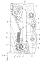
- FIG. 2 is a left side view showing the side stand and its periphery.
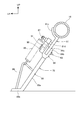
- FIG. 3 is a rear view showing the standing state of the side stand.
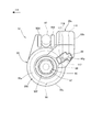
- FIG. 4 is a front view showing the side stand switch.
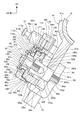
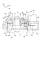
- FIG. 5 is a cross-sectional view showing the side stand switch and its surroundings.
- FIG. 6 is an enlarged cross-sectional view of the main part of FIG.
- FIG. 7 is a cross-sectional view showing the side stand switch of the second embodiment.
- FIG. 8 is a cross-sectional view showing the side stand switch of the third embodiment.
- FIG. 1 is a left side view of a motorcycle 10 provided with a side stand switch 91 according to a first embodiment of the present invention.
- the motorcycle 10 is a scooter type saddle-ride type vehicle having a floor step 57 on which a passenger sitting on a seat 46 puts his / her foot.
- the motorcycle 10 has a front wheel 33 in front of the body frame 11, and a rear wheel 43, which is a driving wheel, is supported by a rear end portion of a unit swing type power unit 21 connected to the rear portion of the body frame 11. .
- the vehicle body frame 11 includes a head pipe 12, a down frame 14, a pair of left and right lower frames 16, and a pair of left and right rear frames 17.
- the head pipe 12 constitutes the front end portion of the vehicle body frame 11.
- the down frame 14 extends downward and obliquely rearward from the head pipe 12.
- the left and right lower frames 16 extend from the lower end of the down frame 14 to the left and right and then extend rearward.
- the rear frame 17 extends rearward and obliquely upward integrally from the rear ends of the lower frames 16 and 16. Further, the rear frame 17 includes a rear frame front portion 17a extending rearward and rearwardly below the seat 46, and a rear frame rear portion 17b extending rearwardly and more gently than the rear frame front portion 17a.
- a front fork 13 is attached to a head pipe 12 so as to be steerable, and a power unit 21 is attached to a lower rear end portion of a lower frame 16 constituting a lower portion of the vehicle body frame 11 via a link 18 so as to be swingable up and down. It has been.
- the front fork 13 includes a steering stem 24 rotatably supported by the head pipe 12, a bottom bridge 25 attached to the lower end portion of the steering stem 24, and buffer portions 26 attached to the left and right end portions of the bottom bridge 25.
- a bar handle 31 is attached to the upper end portion of the steering stem 24, and a front wheel 33 is supported on the lower end portions of the left and right buffer portions 26 via an axle 32.
- the front wheel 33 is covered with a front fender 34 attached to the front fork 13 from above, and a pair of left and right fork guards 30 that protect the front fork 13 are attached to the front fender 34.
- the power unit 21 includes an engine 35 constituting a front portion and a continuously variable transmission 36 provided integrally at a rear portion of the engine 35.
- a cylinder portion including a cylinder head, a cylinder block, and the like extends from the crankcase 37 substantially forward, and an intake device including an air cleaner 38 is connected to the cylinder head.
- the continuously variable transmission 36 includes a transmission case 39 provided integrally with a rear end portion of the crankcase 37, and a rear wheel 43 is attached to the rear end portion of the transmission case 39 via an output shaft 42.
- a rear cushion unit 45 is passed to one rear frame 17 and the transmission case 39.
- the seat 46 is supported by the rear frame 17 via a storage box (not shown) and can be opened and closed.
- a fuel tank 27 is disposed below the rear portion of the seat 46.
- the vehicle body cover 23 includes a front cover 51, a pair of left and right front lower covers 52, a handle cover 53, a front inner cover 54, a leg shield 56, a floor step 57, a pair of left and right floor side skirts 58, and a pair of left and right rear side skirts 59.
- the front cover 51 covers the upper front of the front fork 13.
- the front lower cover 52 is provided at the lower end of the front cover 51.
- the handle cover 53 covers the center portion of the bar handle 31.
- the front inner cover 54 covers the upper rear of the front fork 13.
- the leg shield 56 covers the rear of the upper part of the front fork 13 and is connected to the left and right ends of the front cover 51 to cover the front of the driver's legs.
- the floor step 57 extends downward and rearward from the lower end portion of the leg shield 56 and serves as a driver's footrest.
- the floor side skirt 58 extends downward from left and right edges of the floor step 57.
- the rear side skirt 59 is provided at the rear end of the floor side skirt 58.
- the vehicle body cover 23 includes a center cover 61, a pair of left and right body side covers 62, a rear center cover 63, a pair of left and right body lower covers 64, and a pair of left and right rear side covers 66.
- the center cover 61 extends from the rear end of the floor step 57 to below the front end portion of the seat 46.
- the body side cover 62 extends from the floor step 57 and the center cover 61 below the side edge of the seat 46 to the rear of the vehicle body.
- the rear center cover 63 covers the rear end portions of the left and right body side covers 62 and 62 behind the seat 46.
- the body lower cover 64 extends rearward from the rear end of the floor step 57 along the lower edges of the left and right body side covers 62, 62.
- the rear side cover 66 is connected to the lower edge of the rear end portion of the body side cover 62.
- the fuel tank 27 is covered from the side by the rear portions of the left and right body side covers 62.
- the seat 46 is integrally provided with a front seat 46a on which the driver is seated and a passenger rear seat 46b formed one step higher than the front seat 46a.
- a pair of left and right passenger steps 28 on which the passenger sitting on the rear seat 46b puts his / her foot.
- the front portion of the rear wheel 43 is covered from above by the rear wheel cover 29.
- the handle cover 53 is provided with a headlight 71 at the front, a wind screen 72 at the top, and a pair of left and right rearview mirrors 73 at the left and right ends.
- a foldable side stand 75 is provided on the lower frame 16 on one side (specifically, the left side), and a main stand 76 is provided on the lower portion of the crankcase 37.
- the side stand 75 is provided with a side stand switch (not shown) that detects the standing state.
- a winker 74 is integrally provided on the front cover 51.
- a grab rail 77 that is held by the passenger is provided behind the seat 46.
- the rear wheel 43 is covered from above by a rear fender 79, and the rear fender 79 is provided with a license plate.
- a tail lamp 69 is provided behind the rear side cover 66.
- FIG. 2 is a left side view showing the side stand 75 and its periphery.
- a plate-like stand support bracket 81 is attached to the lower frame 16 (see FIG. 1) on one side (specifically, the left side), and the side stand 75 is rotatably supported by the stand support bracket 81 via a rotation shaft 93. ing.
- the side stand 75 is flipped upward and is in a stored state.
- the side stand 75 includes a stand main body 83 and a spring hooking bar 86 attached to the stand main body 83.
- the stand body 83 includes a base portion 84 and an arm portion 85.
- the base portion 84 is a U-shape that sandwiches the stand support bracket 81 and is a portion that is supported by the rotating shaft 93.
- the arm portion 85 is a portion attached to the base portion 84, and includes a straight portion 85a extending linearly from the base portion 84 and a bent portion 85b bent from the end of the straight portion 85a.
- the bent portion 85b is a portion in contact with the ground.
- the spring hooking bar 86 is attached to the straight portion 85a and the bent portion 85b of the arm portion 85.
- the side stand 75, the spring hook pin 87 attached to the stand support bracket 81 so as to extend to the vehicle body side, and the tension coil spring 88 hung on each of the spring hook bar 86 and the spring hook pin 87 include a side stand assembly 90.
- the tension coil spring 88 biases the side stand 75 so as to hold the housed state or the standing state.
- the stand support bracket 81 is formed with an upright stopper 81a that restricts the rotation position while the side stand 75 is in the upright state, and a storage time stopper (not shown) that restricts the rotation position when the side stand 75 is in the storage state.
- a side stand switch 91 that detects the standing state is attached to the side stand 75.
- the side stand switch 91 is disposed outside the base portion 84 of the side stand 75 in the vehicle width direction.
- the side stand switch 91 may be one that detects the storage state of the side stand 75, or may be one that detects both the standing state and the storage state of the side stand 75.
- FIG. 3 is a rear view showing the standing state of the side stand 75, and shows a partial cross section.
- a stand support bracket 81 is fixed to the lower frame 16, and a side stand 75 is supported by the stand support bracket 81 so as to be swingable.
- the stand support bracket 81 includes a curved portion 81c attached along the surface of the lower frame 16, and a flat stand support portion 81d extending obliquely downward from the lower end of the curved portion 81c.
- a rotation shaft 93 of the side stand 75 is rotatably supported at the lower portion of the stand support portion 81d, and a spring hook pin 87 is attached to an intermediate portion in the vertical direction of the stand support portion 81d.
- a side stand switch 91 is disposed adjacent to the outer surface of the base 84 of the side stand 75.
- the side stand switch 91 includes a non-rotating portion that does not rotate by being locked to the spring hook pin 87 and a rotating portion that rotates together with the side stand 75.
- FIG. 4 is a front view showing the side stand switch 91.
- the side stand switch 91 includes a resin-made switch case 95 that is locked by a spring hook pin 87 and does not rotate, and a rotary portion 96 that is rotatably accommodated in the switch case 95.
- the switch case 95 includes a cylindrical portion 95b having a bottom portion 95a, a pair of locked portions 95d and 95d protruding from a peripheral wall 95c of the cylindrical portion 95b and locked to a spring hook pin 87, and a bottom portion 95a and a cylindrical portion 95b.
- the external connection part 95e extended adjacent to one to-be-latched part 95d from the surrounding wall 95c is provided integrally.
- the cylindrical part 95b is a part that accommodates the rotary part 96 in a rotatable manner.
- a circular opening 95f is opened in the bottom 95a, and a rotary part bolt 97 constituting a part of the rotating shaft 93 projects outward from the opening 95f.
- the external connection unit 95e includes a sensor storage unit 95g that stores a magnetic sensor 98 that detects the rotation of the rotary unit 96, and a connector unit 95h that extracts a detection signal of the magnetic sensor 98 to the outside.
- the sensor storage portion 95g is filled and hardened with resin 99 in a state where the magnetic sensor 98 is stored.
- a connector of a harness extending from an ECU (electronic control unit) provided in the vehicle is connected to the connector portion 95h.
- the rotary part 96 is a part that rotates together with the side stand 75.
- FIG. 5 is a cross-sectional view showing the side stand switch 91 and its surroundings.
- the base 84 of the side stand 75 is integrally formed from a base bottom 84a attached to the arm 85, and a flat inner plate 84b and an outer plate 84c that are bent from both ends of the base bottom 84a and extend in parallel. Yes.
- a screw hole 84d having a female screw is formed in the inner plate portion 84b, and a bolt insertion hole 84e is formed in the outer plate portion 84c.
- the stand support bracket 81 has a bolt insertion hole 81e.
- the stand mounting bolt 103 constituting a part of the rotating shaft 93 is passed through the bolt insertion hole 84e of the outer plate portion 84c of the base portion 84 and the bolt insertion hole 81e of the stand support bracket 81, and the inner plate portion of the base portion 84.
- the screw hole 84d of 84b is screwed.
- the rotating shaft 93 includes a rotary part bolt 97 and a stand mounting bolt 103.
- the stand mounting bolt 103 includes a shaft portion 103a and a head portion 103b formed at one end of the shaft portion 103a.
- the shaft portion 103a includes a cylindrical portion 103c extending adjacent to the head portion 103b, and a screw portion 103e protruding from the tip surface 103d of the cylindrical portion 103c.
- the stand mounting bolt 103 is tightened, the distal end surface 103d of the cylindrical portion 103c is pressed against the inner plate portion 84b, the stand mounting bolt 103 is fixed to the base portion 84, and the side stand 75 and the stand mounting bolt 103 rotate together. It becomes possible to move. Accordingly, the outer peripheral surface 103 g of the columnar portion 103 c of the stand mounting bolt 103 can slide with the bolt insertion hole 81 e of the stand support bracket 81.
- a bottom large diameter hole 95k and a bottom small diameter hole 95m are formed in order from the outside in the vehicle width direction on the inner peripheral surface 95j of the opening 95f of the bottom 95a.
- a bottom step 95n is formed between the bottom large diameter hole 95k and the bottom small diameter hole 95m.
- a peripheral wall small-diameter hole 95q and a peripheral wall large-diameter hole 95r are formed in this order from the bottom 95a side on the inner peripheral surface 95p of the peripheral wall 95c.
- a bottom bottom surface 95t which is the bottom surface of the bottom portion 95a, is formed between the bottom small diameter hole 95m of the bottom portion 95a and the peripheral wall small diameter hole 95q of the peripheral wall 95c.
- a step portion 95s is formed.
- the switch case 95 is formed with an accommodation recess 95u surrounded by a bottom bottom surface 95t, a peripheral wall small diameter hole 95q, a peripheral wall side stepped portion 95s, and a peripheral wall large diameter hole 95r.
- the housing recess 95u opens upward and is largely open downward than the upper opening 95f.
- a rotary part 96 is attached to the stand attachment bolt 103.
- the rotary unit 96 includes a collar assembly 105 that is rotatably supported on the inner peripheral surface 95j of the bottom portion 95a of the switch case 95, a rotor 106 that is rotatably supported on the peripheral wall 95c of the switch case 95, and the color assembly 105. And a rotary part bolt 97 for fixing the rotor 106 to the stand mounting bolt 103.
- the color assembly 105 includes a metal-made cylindrical collar 111 and a resin stepped collar member 112 provided integrally with the collar 111 around the collar 111.
- the stepped collar member 112 includes a large diameter portion 112a, a medium diameter portion 112b, and a small diameter portion 112c in order from the outside in the vehicle width direction.
- An outer step 112d is formed between the large diameter portion 112a and the medium diameter portion 112b, and an inner step 112e is formed between the medium diameter portion 112b and the small diameter portion 112c.
- the outer step 112d is opposed to the bottom step 95n formed on the inner peripheral surface 95j of the switch case 95.
- One end face 106a of the rotor 106 is applied to the inner step 112e.
- the rotor 106 is a cylindrical resin member, an annular convex portion 106c formed so as to protrude from the inner peripheral surface 106b, and a locking pin protruding along the axial direction of the stand mounting bolt 103 from the other end surface 106d. 106e.
- the rotor 106 is rotatably accommodated in the accommodating recess 95u of the switch case 95.
- the outer peripheral surface of the small diameter portion 112c of the stepped collar member 112 is press-fitted into the inner peripheral surface of the annular convex portion 106c.
- the locking pin 106 e is inserted into a pin insertion hole 84 f opened in the outer plate portion 84 c of the side stand 75. Thereby, the side stand 75 and the rotary part 96 can be rotated integrally.
- the outer peripheral surface of the rotor 106 includes a rotor small diameter portion 106f to which the permanent magnet 115 detected by the magnetic sensor 98 is attached, and a rotor large diameter portion 106g having a larger diameter than the rotor small diameter portion 106f.
- a rotor outer peripheral step portion 106h is formed between the rotor small diameter portion 106f and the rotor large diameter portion 106g.
- the rotary part bolt 97 is a part for attaching the collar assembly 105, and thus the rotary part 96, to the stand mounting bolt 103, and the rotary part bolt 97 is screwed into the stand mounting bolt 103 from the head 103b side.
- the magnetic sensor 98 is disposed obliquely upward outward from the permanent magnet 115 so as to be close to the permanent magnet 115.
- the magnetic sensor 98 is provided with a plurality of lead portions 117 for extracting signals, and the connector portion 95 h of the switch case 95 is provided with a plurality of male terminals 118, and the lead portions 117 and the male terminals 118 are connected to each other. ing.
- FIG. 6 is an enlarged cross-sectional view of the main part of FIG.
- a gap 120 is provided between the switch case 95 and the rotary unit 96.
- the gap 120 is formed from the first gap 120a, the second gap 120b, the third gap 120c, the fourth gap 120d, the fifth gap 120e, the sixth gap 120f, and the seventh gap 120g in order from the outside in the axial direction of the stand mounting bolt 103.
- the first gap 120a is a gap between the bottom large-diameter hole 95k of the switch case 95 and the large-diameter part 112a of the stepped collar member 112, and the size of the first gap 120a is C1.
- the second gap 120b is a gap between the bottom step 95n of the switch case 95 and the outer step 112d of the stepped collar member 112, and the size of the second gap 120b is C2.
- the third gap 120c is a gap between the bottom small-diameter hole 95m of the switch case 95 and the middle diameter part 112b of the stepped collar member 112, and the size of the third gap 120c is C3.
- the fourth gap 120d is a gap between the bottom bottom surface 95t of the switch case 95 and the one end face 106a of the rotor 106, and the size of the fourth gap 120d is C4.
- the fifth gap 120e is a gap between the peripheral wall small-diameter hole 95q of the switch case 95 and the rotor small-diameter portion 106f of the rotor 106, and the size of the fifth gap 120e is C5.
- the sixth gap 120f is a gap between the peripheral wall side step portion 95s of the switch case 95 and the rotor outer peripheral step portion 106h of the rotor 106, and the size of the sixth gap 120f is C6.
- the seventh gap 120g is a gap between the peripheral wall large-diameter hole 95r of the switch case 95 and the rotor large-diameter portion 106g of the rotor 106, and the size of the seventh gap 120g is C7.
- the relationship between the sizes C1 to C7 of the first gap 120a to the seventh gap 120g is as follows.
- C5 C6, C6 ⁇ C7.
- each of the first gap 120a to the seventh gap 120g gradually increases as it goes downward. For this reason, it is difficult for dust to enter from the uppermost first gap 120a. Even if the dust enters from the first gap 120a, the dust is likely to fall in the gap 120 due to the gradually increasing gap 120 and is easily discharged. Further, since the lowermost seventh gap 102g is close to the road surface side, the seventh gap 102g is likely to be covered with dust and splashes from the road surface. However, since the seventh gap 102g is a large gap, the dust and splashes once entered the seventh gap 102g. Is easy to be discharged immediately.
- the first gap 120a, the third gap 120c, and the fifth gap 120e, and the second gap 120b, the fourth gap 120d, and the sixth gap 120f are alternately arranged. Since the direction of the gap changes at a right angle, dust and splash are difficult to reach from the seventh gap 102g to the first gap 120a. Therefore, the switch case 95 and the rotary part 96 slide favorably, and wear of the sliding part can be suppressed.
- the side stand switch 91 as a stand switch is provided when the side stand 75 provided in the motorcycle 10 as a motorcycle rotates between the standing position and the storage position.
- a rotary part 96 that can be rotated in accordance with the rotation and a switch case 95 as a case for housing the rotary part 96 are provided.
- the side stand switch 91 detects the position of the side stand 75 by the rotation of the rotary unit 96 with respect to the switch case 95.
- a labyrinth having a bent gap 120 is formed between the rotary portion 96 and the switch case 95. With the side stand switch 91 attached to the motorcycle 10, the gap 120 is lowered from the upper side. I made it bigger.
- the side stand 75 is provided with a pin insertion hole 84f as an engaging portion at an end portion around the rotation shaft 93, and the rotary portion 96 is locked as a positioning pin locked in the pin insertion hole 84f.
- the rotor 106 includes a pin 106e and a permanent magnet 115 that rotates integrally with the locking pin 106e.
- the rotor 106 is accommodated via a gap 120 in an accommodation recess 95u provided in the switch case 95 so as to open downward. According to this configuration, since the gap 120 is formed facing the opening of the housing recess 95u that opens downward, dust discharge can be improved.
- the switch case 95 includes a cylindrical peripheral wall 95c, a bottom portion 95a formed at one end of the peripheral wall 95c, a pair of locked portions 95d serving as a detent portion that engages with the vehicle body, and a permanent magnet 115. And a sensor storage portion 95g in which a magnetic sensor 98 is disposed so as to be close to each other.
- a collar assembly 105 as a collar member attached to the rotating shaft 93 and having a step in the radial direction is disposed on the inner side in the radial direction of the bottom portion 95a. According to this configuration, the entry of dust into the gap 120 can be suppressed by the step portion of the collar assembly 105 having a step in the radial direction.
- the collar assembly 105 includes an outer step portion 112d as a first step portion that slidably holds the bottom portion 95a. According to this configuration, entry of dust into the sliding portion can be suppressed by the outer stepped portion 112d.
- the collar assembly 105 includes an inner step 112e as a second step for positioning the rotor 106 in the axial direction. According to this configuration, entry of dust into the sliding portion can be suppressed by the inner stepped portion 112e.
- the collar assembly 105 includes a collar 111 as a metal cylinder on the rotating shaft 93 side, and a resin stepped collar member 112 integrally provided on the outer periphery of the collar 111.
- the end surface 103f of the rotation shaft 93 is brought into contact with one end of the collar 111 in the axial direction, and further, the rotary shaft bolt 97 serving as a fastening bolt constituting the rotation shaft 93 from the outside of the other end in the axial direction. It is fixed to the end face 103f. According to this configuration, the collar assembly 105 is fastened and fixed by the metal collar 111, the burden on the resin stepped collar member 112 is reduced, and durability can be improved.
- the rotor 106 is housed in a housing recess 95 u provided in the switch case 95 and opening downward.
- the rotor 106 includes a rotor small diameter portion 106f as a small diameter portion provided on the bottom portion 95a side, and a rotor large diameter portion 106g as a large diameter portion provided on the opening side of the housing recess 95u with respect to the rotor small diameter portion 106f.
- the seventh gap 120g which is the gap between the housing recess 95u and the rotor large diameter portion 106g, may be made larger than the fifth gap 120e that is the gap between the housing recess 95u and the rotor small diameter portion 106f.
- a bent labyrinth is formed by the rotor small-diameter portion 106f and the rotor large-diameter portion 106g of the rotor 106, and the seventh gap 120g between the housing recess 95u and the rotor large-diameter portion 106g is larger. Can be promoted.
- the fifth gap 120e which is the gap between the housing recess 95u and the rotor small diameter part 106f, is made larger than the fourth gap 120d, which is the gap between the bottom 95a of the switch case 95 and the rotor 106. According to this configuration, dust that has entered from the sliding portion can be smoothly discharged because the fifth gap 120e between the accommodating recess 95u and the rotor small diameter portion 106f is wide.
- FIG. 7 is a cross-sectional view showing the side stand switch 121 of the second embodiment.
- the same components as those in the first embodiment shown in FIGS. 5 and 6 are denoted by the same reference numerals, and detailed description thereof is omitted.
- the side stand switch 121 is different from the side stand switch 91 (see FIG. 6) in a switch case 122 and a rotary part 123.
- the switch case 122 includes a cylindrical portion 122b having a bottom portion 95a, a pair of locked portions 95d protruding from the peripheral wall 122c of the cylindrical portion 122b and locked to a spring hook pin 87 (see FIG. 5), a bottom portion 95a and a cylindrical portion.
- the external connection part 95e extended adjacent to one to-be-latched part 95d from the surrounding wall 122c of the part 122b is integrally provided.
- the cylindrical part 122b is a part that accommodates the rotary part 123 in a rotatable manner.
- the rotary part 123 is a part that rotates together with the side stand 75 (see FIG. 5).
- the switch case 95 is formed with an accommodation recess 122u surrounded by a bottom bottom surface 95t and a tapered inner peripheral surface 122p.
- the housing recess 122u opens upward and opens largely below the opening 95f.
- a rotary part 123 is attached to the stand attachment bolt 103.
- the rotary portion 123 includes a collar assembly 105 that is rotatably supported on the inner peripheral surface 95j of the bottom portion 95a of the switch case 122, a rotor 126 that is rotatably supported on the peripheral wall 122c of the switch case 122, and the color assembly 105. And a rotary part bolt 97 for fixing the rotor 126 to the stand mounting bolt 103.
- the first gap 120a to the fourth gap 120d are provided between the inner peripheral surface of the switch case 122 and the rotary part 123, as in the case between the switch case 95 and the rotary part 196 shown in FIG. ing.
- the size of the gap 120h between the upper end of the tapered inner peripheral surface 122p of the switch case 122 and the outer peripheral surface of the rotor 126 is C5, which is the same as the fifth gap 120e (see FIG. 6), and the size of the gap 120h is As it goes down, it gradually increases from C5.
- the gap 120h between the housing recess 122u and the rotor 126 has an expanded shape so as to gradually increase toward the opening end of the housing recess 122u. According to this configuration, dust discharge can be further improved.
- FIG. 8 is a cross-sectional view showing the side stand switch 131 of the third embodiment.
- the side stand switch 131 includes a switch case 95 and a rotary part 133 that is rotatably accommodated in the switch case 95.
- the rotary part 133 is a part that rotates together with the side stand 75 (see FIG. 5).
- the rotary portion 133 includes a flanged cylindrical collar 135 that is rotatably supported on the inner peripheral surface 95j of the bottom portion 95a of the switch case 95, and a rotor 136 that is rotatably supported on the peripheral wall 95c of the switch case 95.
- a rotary part bolt 97 for fixing the collar 135 and the rotor 136 to the stand mounting bolt 103.
- the collar 135 is made of metal, and includes a cylinder part 135a and a flange part 135b formed integrally with the cylinder part 135a, and supports an axial force when the rotary part bolt 97 is tightened.
- the cylindrical portion 135a of the collar 135 includes a collar large diameter portion 135c and a collar small diameter portion 135d in order from the outside in the vehicle width direction.
- An outer step portion 135e is formed between the flange portion 135b and the collar large diameter portion 135c of the tube portion 135a, and an inner step portion 135f is formed between the collar large diameter portion 1135c and the collar small diameter portion 135d.
- the outer step portion 135e faces the bottom step portion 95n of the switch case 95.
- One end face 106a of the rotor 136 is applied to the inner stepped portion 135f.
- the rotor 136 is a cylindrical resin member, and an annular convex portion 106c formed so as to protrude from the inner peripheral surface 106b, and a locking pin that protrudes along the axial direction of the stand mounting bolt 103 from the other end surface 106d. 106e.
- the outer peripheral surface of the collar small-diameter portion 135d of the collar 135 is press-fitted into the inner peripheral surface of the annular convex portion 106c.
- the outer peripheral surface of the rotor 136 includes a rotor small-diameter portion 136f to which the permanent magnet 115 detected by the magnetic sensor 98 is attached, and a rotor large-diameter portion 136g having a larger diameter than the rotor small-diameter portion 136f.
- a rotor outer circumferential step portion 136h is formed between the rotor small diameter portion 136f and the rotor large diameter portion 136g.
- the inner peripheral surface of the switch case 95 specifically, the bottom step portion 95n, the bottom small diameter hole 95m, the bottom bottom surface 95t, the peripheral wall small diameter hole 95q, the peripheral wall side step portion 95s, and the peripheral wall large diameter hole 95r are coated with fluorine resin 138. ing.
- a gap 120 is provided between the fluorine resin 138 on the inner peripheral surface of the switch case 95 and the rotary part 133 in the same manner as between the switch case 95 and the rotary part 196 shown in FIG. Since the fluororesin 138 has a small friction coefficient, the sliding between the switch case 95 and the rotary part 133 can be improved. Further, even when muddy water or the like entering the gap 120 is frozen, the rotation of the rotary part 133 relative to the switch case 95 can be urged by a small coefficient of friction.
- the above-described embodiment is merely an aspect of the present invention, and is not limited to a side stand, and may be a main stand, or may be another stand, a folding arm, a lever, or the like.
- the invention is not limited to two-wheeled vehicles, and can be arbitrarily modified and applied without departing from the gist of the present invention.
Landscapes
- Engineering & Computer Science (AREA)
- Mechanical Engineering (AREA)
- Rotary Switch, Piano Key Switch, And Lever Switch (AREA)
Abstract
Description
本発明の目的は、パッキンを使用せずに簡素化でき、また、耐久性を向上できるスタンドスイッチを提供することにある。
本発明は、二輪車(10)等の鞍乗り型車両に設けられるスタンド(75)が起立位置と収納位置との間で回動する際に、その回動に伴って回動可能なロータリー部(96,123,133)と、前記ロータリー部(96,123,133)を収容するケース(95,122)と備え、前記ケース(95,122)に対する前記ロータリー部(96,123,133)の回動により前記スタンド(75)の位置を検出するスタンドスイッチにおいて、前記ロータリー部(96,123,133)と、前記ケース(95,122)との間に、屈曲した隙間(120)を有するラビリンスを形成し、前記二輪車(10)に装着した状態で、前記隙間(120)を上側より下側の方で大きくしたことを特徴とする。
また、上記発明において、前記カラー部材(105,135)は、前記ロータ(106,136)を軸方向に位置決めする第2段部(112e,135f)を備えるようにしても良い。
また、上記発明において、前記収容凹部(122u)と前記ロータ(126)との隙間(120h)を、前記収容凹部(122u)の開口端に向かうにつれて次第に大きくなるように拡開形状としても良い。
また、上記発明において、カラー部材は、ロータを軸方向に位置決めする第2段部を備えるので、第2段部により摺動部への塵埃の進入を抑制できる。
また、上記発明において、収容凹部とロータとの隙間を、収容凹部の開口端に向かうにつれて次第に大きくなるように拡開形状としたので、塵埃の排出をより一層向上できる。
<第1実施形態>
図1は、本発明に係る第1実施形態のサイドスタンドスイッチ91を備えた自動二輪車10の左側面図である。
自動二輪車10は、シート46に着座した乗員が足を載せるフロアステップ57を有するスクータ型の鞍乗り型車両である。自動二輪車10は、車体フレーム11の前方に前輪33を有し、駆動輪である後輪43は、車体フレーム11の後部に連結されるユニットスイング型のパワーユニット21の後端部に支持されている。
車体フレーム11は、ヘッドパイプ12、ダウンフレーム14、左右一対のロアフレーム16及び左右一対のリヤフレーム17を備える。
ヘッドパイプ12は、車体フレーム11の前端部を構成している。ダウンフレーム14は、ヘッドパイプ12から下方斜め後方に延びる。左右のロアフレーム16は、ダウンフレーム14の下端から左右に延びた後、後方に延びる。リヤフレーム17は、ロアフレーム16,16の後端から一体に後方斜め上方に延びる。また、リヤフレーム17は、シート46の下方を後ろ上がりに後方に延びるリヤフレーム前部17aと、リヤフレーム前部17aよりも緩い傾斜で後ろ上がりに延びるリヤフレーム後部17bとを有する。
自動二輪車10は、ヘッドパイプ12に操舵可能にフロントフォーク13が取付けられ、車体フレーム11の下部を構成するロアフレーム16の下部後端部にリンク18を介して上下揺動可能にパワーユニット21が取付けられている。
フロントフォーク13は、ヘッドパイプ12に回転可能に支持されたステアリングステム24と、ステアリングステム24の下端部に取付けられたボトムブリッジ25と、ボトムブリッジ25の左右両端部に取付けられた緩衝部26とから構成されている。ステアリングステム24の上端部にはバーハンドル31が取付けられ、左右の緩衝部26の下端部には、車軸32を介して前輪33が支持されている。前輪33は、上方からフロントフォーク13に取付けられたフロントフェンダ34で覆われ、フロントフェンダ34にフロントフォーク13を保護する左右一対のフォークガード30が取付けられている。
車体カバー23は、フロントカバー51、左右一対のフロントロアカバー52、ハンドルカバー53、フロントインナカバー54、レッグシールド56、フロアステップ57、左右一対のフロアサイドスカート58、左右一対のリヤサイドスカート59を備える。
フロントカバー51は、フロントフォーク13の上部の前方を覆う。フロントロアカバー52は、フロントカバー51の下端に設けられる。ハンドルカバー53は、バーハンドル31の中央部を覆う。フロントインナカバー54は、フロントフォーク13の上部の後方を覆う。レッグシールド56は、フロントフォーク13の上部の後方を覆うとともにフロントカバー51の左右端に接続されて運転者の脚部の前方を覆う。フロアステップ57は、レッグシールド56の下端部から下方及び後方に延びて運転者の足載せとされる。フロアサイドスカート58は、フロアステップ57の左右縁部から下方に延びる。リヤサイドスカート59は、フロアサイドスカート58の後端に設けられる。
センタカバー61は、フロアステップ57の後端からシート46の前端部下方まで延びる。ボディサイドカバー62は、フロアステップ57及びセンタカバー61からシート46の側縁下方を車体後方に延びる。リヤセンタカバー63は、シート46の後方で左右のボディサイドカバー62,62の後端部間を覆う。ボディロアカバー64は、左右のボディサイドカバー62,62の下縁に沿ってフロアステップ57の後端から後方へ延びる。リアサイドカバー66は、ボディサイドカバー62の後端部下縁に接続される。
シート46は、運転者が着座する前部シート46aと、前部シート46aより一段高く形成された同乗者用の後部シート46bとを一体に備える。ボディロアカバー64の下端部には、後部シート46bに着座した同乗者が足を載せる可倒式の左右一対の同乗者用ステップ28が設けられている。また、後輪43の前部は、後輪カバー29によって上方から覆われている。
フロントカバー51には、ウインカ74が一体的に設けられている。シート46の後方には、同乗者が掴むグラブレール77が設けられている。後輪43はリヤフェンダ79によって上方から覆われ、リヤフェンダ79にはライセンスプレートが設けられる。リアサイドカバー66の後方には、テールランプ69が設けられる。
一側(詳しくは、左側)のロアフレーム16(図1参照)に板状のスタンド支持ブラケット81が取付けられ、スタンド支持ブラケット81に回動軸93を介してサイドスタンド75が回動可能に支持されている。サイドスタンド75は、上方に跳ね上げられて収納状態にある。
サイドスタンド75は、スタンド本体83と、スタンド本体83に取付けられたばね掛けバー86とからなる。スタンド本体83は、基部84及びアーム部85からなる。
基部84は、スタンド支持ブラケット81を挟み込むU字状を成し、回動軸93に支持される部分である。アーム部85は、基部84に取付けられた部分であり、基部84から直線状に延びる直線部85aと、直線部85aの端部から屈曲した屈曲部85bとからなる。屈曲部85bは、地面に接する部分である。ばね掛けバー86は、アーム部85の直線部85aと屈曲部85bとに渡されて取付けられている。
引張コイルばね88は、サイドスタンド75を収納状態又は起立状態を保持するように付勢する。
スタンド支持ブラケット81には、サイドスタンド75を起立状態に回動位置を規制する起立時ストッパ81aと、サイドスタンド75を収納状態に回動位置を規制する収納時ストッパ(不図示)とが形成されている。
サイドスタンド75には、例えば、その起立状態を検知するサイドスタンドスイッチ91が付設されている。サイドスタンドスイッチ91は、サイドスタンド75の基部84の車幅方向外側に配置されている。
なお、サイドスタンドスイッチ91は、サイドスタンド75の収納状態を検知するものでも良く、あるいは、サイドスタンド75の起立状態と収納状態との両方を検知するものでも良い。
ロアフレーム16にスタンド支持ブラケット81が固定され、スタンド支持ブラケット81に揺動可能にサイドスタンド75が支持されている。
スタンド支持ブラケット81は、ロアフレーム16の表面に沿って取付けられた湾曲部81cと湾曲部81cの下端から下方斜め側方に延びる平板状のスタンド支持部81dとを備える。
スタンド支持部81dの下部には、サイドスタンド75の回動軸93が回動可能に支持され、スタンド支持部81dの上下方向の中間部には、ばね掛けピン87が取付けられている。
サイドスタンド75の基部84の外側面に隣接してサイドスタンドスイッチ91が配置されている。サイドスタンドスイッチ91は、ばね掛けピン87に係止されることで回動しない非回動部分と、サイドスタンド75と共に回動する回動部分とから構成されている。
サイドスタンドスイッチ91は、ばね掛けピン87に係止されて回動しない樹脂製のスイッチケース95と、スイッチケース95に回動可能に収容されたロータリー部96とから構成されている。
スイッチケース95は、底部95aを有する円筒部95bと、円筒部95bの周壁95cから突出してばね掛けピン87に係止される一対の被係止部95d,95dと、底部95a及び円筒部95bの周壁95cから一方の被係止部95dに隣接して延びる外部接続部95eとを一体に備える。
円筒部95bは、ロータリー部96を回動可能に収容する部分である。底部95aには、円形の開口95fが開けられ、開口95fから回動軸93の一部を構成するロータリー部ボルト97が外方に突出している。外部接続部95eは、ロータリー部96の回動を検知する磁気センサ98が収納されたセンサ収納部95gと、磁気センサ98の検出信号を外部に取り出すコネクタ部95hとを備える。センサ収納部95gには、磁気センサ98が収納された状態で樹脂99が充填されて固められている。コネクタ部95hには、車両に備えるECU(電子制御ユニット)から延びるハーネスのコネクタが接続される。
ロータリー部96は、サイドスタンド75と共に回動する部分である。
サイドスタンド75の基部84は、アーム部85に取付けられた基部底部84aと、基部底部84aの両端から屈曲して平行に延びる平板状の内板部84b及び外板部84cとから一体に形成されている。
内板部84bには雌ねじを有するねじ穴84dが形成され、外板部84cにはボルト挿通穴84eが開けられている。
スタンド支持ブラケット81には、ボルト挿通穴81eが開けられている。
回動軸93の一部を構成するスタンド取付ボルト103は、基部84の外板部84cのボルト挿通穴84e及びスタンド支持ブラケット81のボルト挿通穴81eに通されるとともに、基部84の内板部84bのねじ穴84dにねじ結合されている。回動軸93は、ロータリー部ボルト97及びスタンド取付ボルト103からなる。
スタンド取付ボルト103を締め付けた状態では、円柱部103cの先端面103dが内板部84bに押し当てられ、スタンド取付ボルト103が基部84に固定され、サイドスタンド75とスタンド取付ボルト103とが一体に回動可能になる。従って、スタンド取付ボルト103の円柱部103cの外周面103gが、スタンド支持ブラケット81のボルト挿通穴81eと摺動可能になる。
また、周壁95cの内周面95pには、底部95a側から順に周壁小径穴95q、周壁大径穴95rが形成されている。底部95aの底部小径穴95mと周壁95cの周壁小径穴95qとの間には底部95aの底面である底部底面95tが形成され、周壁小径穴95qと周壁大径穴95rとの間には周壁側段部95sが形成されている。
スイッチケース95は、底部底面95t、周壁小径穴95q、周壁側段部95s及び周壁大径穴95rで囲まれる収容凹部95uが形成されている。収容凹部95uは、上方に開口するとともに、上方の開口95fよりも下方に大きく開放されている。
ロータリー部96は、スイッチケース95の底部95aの内周面95jに回動可能に支持されるカラーアッシー105と、スイッチケース95の周壁95cに回動可能に支持されるロータ106と、カラーアッシー105及びロータ106をスタンド取付ボルト103に固定するロータリー部ボルト97とから構成される。
カラーアッシー105は、金属製で筒状のカラー111と、カラー111の周囲にカラー111と一体的に設けられた樹脂製の段付きカラー部材112とからなる。
段付きカラー部材112は、車幅方向外側から順に、大径部112a、中径部112b、小径部112cを備える。大径部112aと中径部112bとの間には外側段部112dが形成され、中径部112bと小径部112cとの間には内側段部112eが形成されている。
外側段部112dは、スイッチケース95の内周面95jに形成された底部段部95nが対向している。内側段部112eにはロータ106の一端面106aが当てられる。
環状凸部106cの内周面には、段付きカラー部材112の小径部112cの外周面が圧入されている。
係止ピン106eは、サイドスタンド75の外板部84cに開けられたピン挿通穴84fに挿入されている。これにより、サイドスタンド75とロータリー部96とが一体に回動可能になる。
ロータリー部ボルト97は、カラーアッシー105、ひいては、ロータリー部96をスタンド取付ボルト103に取付ける部品であり、ロータリー部ボルト97が、スタンド取付ボルト103に頭部103b側からねじ込まれている。
磁気センサ98は、永久磁石115に近接するように、永久磁石115に対して外側方斜め上方に配置されている。磁気センサ98には信号を取り出す複数のリード部117が設けられ、また、スイッチケース95のコネクタ部95hには複数の雄型端子118が設けられ、リード部117と雄型端子118とが接続されている。
スイッチケース95と、ロータリー部96との間には隙間120が設けられている。
隙間120は、スタンド取付ボルト103の軸方向外側から順に、第1隙間120a、第2隙間120b、第3隙間120c、第4隙間120d、第5隙間120e、第6隙間120f及び第7隙間120gからなる。
第1隙間120aは、スイッチケース95の底部大径穴95kと、段付きカラー部材112の大径部112aとの隙間であり、第1隙間120aの大きさは、C1である。
第2隙間120bは、スイッチケース95の底部段部95nと、段付きカラー部材112の外側段部112dとの隙間であり、第2隙間120bの大きさは、C2である。
第3隙間120cは、スイッチケース95の底部小径穴95mと、段付きカラー部材112の中径部112bとの隙間であり、第3隙間120cの大きさは、C3である。
第5隙間120eは、スイッチケース95の周壁小径穴95qと、ロータ106のロータ小径部106fとの隙間であり、第5隙間120eの大きさは、C5である。
第6隙間120fは、スイッチケース95の周壁側段部95sと、ロータ106のロータ外周段部106hとの間の隙間であり、第6隙間120fの大きさは、C6である。
第7隙間120gは、スイッチケース95の周壁大径穴95rと、ロータ106のロータ大径部106gとの隙間であり、第7隙間120gの大きさは、C7である。
各第1隙間120a~第7隙間120gの大きさC1~C7の関係は、以下のようになる。C1=C2、C2<C3、C3=C4、C4<C5、C5=C6、C6<C7となる。
更に、隙間120では、第1隙間120a、第3隙間120c、第5隙間120eと、第2隙間120b、第4隙間120d、第6隙間120fとが、交互になって配置され、そのたびに、隙間の方向が直角に変化するため、塵埃や水しぶきが第7隙間102gから第1隙間120aまでは届きにくい。
従って、スイッチケース95とロータリー部96とが良好に摺動し、摺動部の摩耗を抑制することができる。
サイドスタンドスイッチ91には、ロータリー部96と、スイッチケース95との間に、屈曲した隙間120を有するラビリンスを形成し、自動二輪車10にサイドスタンドスイッチ91を装着した状態で、隙間120を上側より下側の方で大きくした。
この構成によれば、下方に開放する収容凹部95uの開口に面して隙間120が形成されるので、塵埃の排出を向上できる。
この構成によれば、径方向に段差を有するカラーアッシー105の段部により隙間120への塵埃の進入を抑制できる。
この構成によれば、外側段部112dにより摺動部への塵埃の進入を抑制できる。
また、カラーアッシー105は、ロータ106を軸方向に位置決めする第2段部としての内側段部112eを備える。
この構成によれば、内側段部112eにより摺動部への塵埃の進入を抑制できる。
この構成によれば、カラーアッシー105は金属製のカラー111で締結固定され、樹脂製の段付きカラー部材112への負担が少なくなり、耐久性を向上できる。
この構成によれば、ロータ106のロータ小径部106fとロータ大径部106gとにより屈曲したラビリンスが形成され、収容凹部95uとロータ大径部106gとの第7隙間120gの方が大きいので、塵埃の排出を促すことができる。
この構成によれば、摺動部から侵入した塵埃も、収容凹部95uとロータ小径部106fとの第5隙間120eが広いので、円滑に排出できる。
図7は、第2実施形態のサイドスタンドスイッチ121を示す断面図である。
図5、図6に示した第1実施形態と同一構成については同一符号を付け、詳細説明は省略する。
サイドスタンドスイッチ121は、サイドスタンドスイッチ91(図6参照)に対してスイッチケース122及びロータリー部123が異なる。
スイッチケース122は、底部95aを有する円筒部122bと、円筒部122bの周壁122cから突出してばね掛けピン87(図5参照)に係止される一対の被係止部95dと、底部95a及び円筒部122bの周壁122cから一方の被係止部95dに隣接して延びる外部接続部95eとを一体に備える。
円筒部122bは、ロータリー部123を回動可能に収容する部分である。
ロータリー部123は、サイドスタンド75(図5参照)と共に回動する部分である。
スイッチケース95には、底部底面95t及びテーパー状内周面122pで囲まれる収容凹部122uが形成されている。収容凹部122uは、上方に開口するとともに、開口95fよりも下方に大きく開放している。
スタンド取付ボルト103には、ロータリー部123が取付けられている。
ロータリー部123は、スイッチケース122の底部95aの内周面95jに回動可能に支持されるカラーアッシー105と、スイッチケース122の周壁122cに回動可能に支持されるロータ126と、カラーアッシー105及びロータ126をスタンド取付ボルト103に固定するロータリー部ボルト97とから構成される。
このような隙間120hを設けることで、スイッチケース122の内周面とロータリー部123との隙間に溜まった塵埃等の排出を促すことができる。また、下方から隙間120hに入り込んだ塵埃や泥水等の排出も促すことができる。
この構成によれば、塵埃の排出をより一層向上できる。
図8は、第3実施形態のサイドスタンドスイッチ131を示す断面図である。
サイドスタンドスイッチ131は、スイッチケース95と、スイッチケース95に回動可能に収容されたロータリー部133とから構成されている。
ロータリー部133は、サイドスタンド75(図5参照)と共に回動する部分である。
ロータリー部133は、スイッチケース95の底部95aの内周面95jに回動可能に支持されるフランジ付き円筒状のカラー135と、スイッチケース95の周壁95cに回動可能に支持されるロータ136と、カラー135及びロータ136をスタンド取付ボルト103に固定するロータリー部ボルト97とから構成される。
カラー135の筒部135aは、車幅方向外側から順に、カラー大径部135c及びカラー小径部135dを備える。
フランジ部135bと筒部135aのカラー大径部135cとの間には外側段部135eが形成され、カラー大径部1135cとカラー小径部135dとの間には内側段部135fが形成されている。
外側段部135eは、スイッチケース95の底部段部95nに対向している。内側段部135fにはロータ136の一端面106aが当てられる。
環状凸部106cの内周面には、カラー135のカラー小径部135dの外周面が圧入されている。
ロータ136の外周面は、磁気センサ98によって検知される永久磁石115が取付けられたロータ小径部136fと、ロータ小径部136fよりも大径とされたロータ大径部136gとを備える。ロータ小径部136fとロータ大径部136gとの間にはロータ外周段部136hが形成されている。
スイッチケース95の内周面のふっ素樹脂138と、ロータリー部133との間には、図5に示したスイッチケース95とロータリー部196との間と同じように、隙間120が設けられている。
ふっ素樹脂138は、摩擦係数が小さいため、スイッチケース95と、ロータリー部133との摺動を良好にすることができる。また、隙間120に入り込んだ泥水等が凍った場合でも、小さな摩擦係数によって、スイッチケース95に対するロータリー部133の回動を促すことができる。
75 サイドスタンド
84f ピン挿通穴(係合部)
91,121,131 サイドスタンドスイッチ(スタンドスイッチ)
93 回動軸
95,122 スイッチケース(ケース)
95a 底部
95c,122c 周壁
95d 被係止部(廻り止め部)
95g センサ収納部
95u,122u 収容凹部
96,123,133 ロータリー部
97c 内側端面(端面)
98 磁気センサ
103f 端面
105 カラーアッシー
106,126,136 ロータ
106e 係止ピン(位置決めピン)
106f ロータ小径部(小径部)
106g ロータ大径部(大径部)
111 カラー(筒体)
112 段付きカラー部材
112d,135e 外側段部(第1段部)
112e,135f 内側段部(第2段部)
115 永久磁石
120 隙間
120e 第5隙間(隙間)
120g 第7隙間(隙間)
135 カラー(カラー部材)
Claims (9)
- 二輪車(10)に設けられるスタンド(75)が起立位置と収納位置との間で回動する際に、その回動に伴って回動可能なロータリー部(96,123,133)と、前記ロータリー部(96,123,133)を収容するケース(95,122)と備え、前記ケース(95,122)に対する前記ロータリー部(96,123,133)の回動により前記スタンド(75)の位置を検出するスタンドスイッチにおいて、
前記ロータリー部(96,123,133)と、前記ケース(95,122)との間に、屈曲した隙間(120)を有するラビリンスを形成し、前記二輪車(10)に装着した状態で、前記隙間(120)を上側より下側の方で大きくしたことを特徴とするスタンドスイッチ。 - 前記スタンド(75)は、その回動軸(93)の周囲の端部に係合部(84f)が設けられ、
前記ロータリー部(96,123,133)は、前記係合部(84f)に係止される位置決めピン(106e)と、前記位置決めピン(106e)と共に一体に回転する永久磁石(115)とを備えるロータ(106,126,136)を含み、前記ロータ(106,126,136)は、前記ケース(95,122)に下方に開放するように設けられた収容凹部(95u,122u)に前記隙間(120)を介して収容されることを特徴とする請求項1に記載のスタンドスイッチ。 - 前記ケース(95,122)は、筒状の周壁(95c,122c)と、前記周壁(95c,122c)の一端に形成された底部(95a)と、車体側に係合する廻り止め部(95d,95d)と、前記永久磁石(115)に近接するように配置される磁気センサ(98)が配置されたセンサ収納部(95g)とを備え、前記底部(95a)の径方向内側に、前記回動軸(93)に取付けられるとともに径方向の段差を有するカラー部材(105,135)が配置されることを特徴とする請求項1又は2に記載のスタンドスイッチ。
- 前記カラー部材(105,135)は、前記底部(95a)を摺動自在に保持する第1段部(112d,135e)を備えることを特徴とする請求項3項記載のスタンドスイッチ。
- 前記カラー部材(105,135)は、前記ロータ(106,136)を軸方向に位置決めする第2段部(112e,135f)を備えることを特徴とする請求項2に記載のスタンドスイッチ。
- 前記カラー部材(105)は、前記回動軸(93)側に金属製の筒体(111)と、前記筒体(111)の外周に一体的に設けられた樹脂製の段付きカラー部材(112)とを備え、前記筒体(111)の軸方向一端に前記回動軸(93)の端面(103f)を当接させ、更に、軸方向他端の外側から前記回動軸(93)を構成する締結ボルト(97)にて前記回動軸(93)の端面(103f)に固定されることを特徴とする請求項3乃至5のいずれか一項に記載のスタンドスイッチ。
- 前記ロータ(106)は、前記ケース(95)に設けられた下方に開口する前記収容凹部(95u)内に収納され、前記ロータ(106)は、前記底部(95a)側に設けられた小径部(106f)と、前記小径部(106f)に対して前記収容凹部(95u)の開口側に設けられた大径部(106g)とを備え、前記収容凹部(95u)と前記小径部(106f)との隙間(120e)に対し、前記収容凹部(95u)と前記大径部(106g)との隙間(120g)を大きくしたことを特徴とする請求項1乃至6のいずれか一項に記載のスタンドスイッチ。
- 前記ケース(95)の底部(95a)と前記ロータ(106)との隙間(120d)に対し、収容凹部(95u)と前記小径部(106f)との隙間(120e)を大きくしたことを特徴とする請求項7に記載のスタンドスイッチ。
- 前記収容凹部(122u)と前記ロータ(126)との隙間(120h)を、前記収容凹部(122u)の開口端に向かうにつれて次第に大きくなるように拡開形状としたことを特徴とする請求項8に記載のスタンドスイッチ。
Priority Applications (4)
| Application Number | Priority Date | Filing Date | Title |
|---|---|---|---|
| JP2018558922A JP6670955B2 (ja) | 2016-12-28 | 2017-11-29 | スタンドスイッチ |
| CN201780078273.XA CN110087980B (zh) | 2016-12-28 | 2017-11-29 | 支架开关 |
| MYPI2019003312A MY196144A (en) | 2016-12-28 | 2017-11-29 | Stand Switch |
| BR112019007669A BR112019007669A2 (pt) | 2016-12-28 | 2017-11-29 | comutador de descanso |
Applications Claiming Priority (2)
| Application Number | Priority Date | Filing Date | Title |
|---|---|---|---|
| JP2016255306 | 2016-12-28 | ||
| JP2016-255306 | 2016-12-28 |
Publications (1)
| Publication Number | Publication Date |
|---|---|
| WO2018123404A1 true WO2018123404A1 (ja) | 2018-07-05 |
Family
ID=62707309
Family Applications (1)
| Application Number | Title | Priority Date | Filing Date |
|---|---|---|---|
| PCT/JP2017/042750 Ceased WO2018123404A1 (ja) | 2016-12-28 | 2017-11-29 | スタンドスイッチ |
Country Status (5)
| Country | Link |
|---|---|
| JP (1) | JP6670955B2 (ja) |
| CN (1) | CN110087980B (ja) |
| BR (1) | BR112019007669A2 (ja) |
| MY (1) | MY196144A (ja) |
| WO (1) | WO2018123404A1 (ja) |
Cited By (2)
| Publication number | Priority date | Publication date | Assignee | Title |
|---|---|---|---|---|
| JPWO2020217803A1 (ja) * | 2019-04-26 | 2021-11-25 | 本田技研工業株式会社 | サイドスタンド構造 |
| EP4778813A1 (en) | 2025-01-16 | 2026-07-22 | Suzuki Motor Corporation | Saddle-type vehicle |
Citations (4)
| Publication number | Priority date | Publication date | Assignee | Title |
|---|---|---|---|---|
| JPH03164387A (ja) * | 1990-11-20 | 1991-07-16 | Honda Motor Co Ltd | サイドスタンドの状態検出装置 |
| JP2008130314A (ja) * | 2006-11-20 | 2008-06-05 | Toyo Denso Co Ltd | スイッチ装置及び該装置の製造方法 |
| JP2012056346A (ja) * | 2010-09-06 | 2012-03-22 | Alps Electric Co Ltd | サイドスタンドスイッチおよびサイドスタンド装置 |
| JP2016064694A (ja) * | 2014-09-24 | 2016-04-28 | 本田技研工業株式会社 | センサ配置構造 |
Family Cites Families (3)
| Publication number | Priority date | Publication date | Assignee | Title |
|---|---|---|---|---|
| JP4771420B2 (ja) * | 2006-01-12 | 2011-09-14 | 本田技研工業株式会社 | サイドスタンドスイッチ |
| JP2008084615A (ja) * | 2006-09-26 | 2008-04-10 | Matsushita Electric Works Ltd | ロータリスイッチ |
| CN101875376B (zh) * | 2009-04-30 | 2012-12-19 | 阿尔卑斯电气株式会社 | 侧支架开关和侧支架装置 |
-
2017
- 2017-11-29 BR BR112019007669A patent/BR112019007669A2/pt not_active Application Discontinuation
- 2017-11-29 WO PCT/JP2017/042750 patent/WO2018123404A1/ja not_active Ceased
- 2017-11-29 CN CN201780078273.XA patent/CN110087980B/zh not_active Expired - Fee Related
- 2017-11-29 JP JP2018558922A patent/JP6670955B2/ja active Active
- 2017-11-29 MY MYPI2019003312A patent/MY196144A/en unknown
Patent Citations (4)
| Publication number | Priority date | Publication date | Assignee | Title |
|---|---|---|---|---|
| JPH03164387A (ja) * | 1990-11-20 | 1991-07-16 | Honda Motor Co Ltd | サイドスタンドの状態検出装置 |
| JP2008130314A (ja) * | 2006-11-20 | 2008-06-05 | Toyo Denso Co Ltd | スイッチ装置及び該装置の製造方法 |
| JP2012056346A (ja) * | 2010-09-06 | 2012-03-22 | Alps Electric Co Ltd | サイドスタンドスイッチおよびサイドスタンド装置 |
| JP2016064694A (ja) * | 2014-09-24 | 2016-04-28 | 本田技研工業株式会社 | センサ配置構造 |
Cited By (6)
| Publication number | Priority date | Publication date | Assignee | Title |
|---|---|---|---|---|
| JPWO2020217803A1 (ja) * | 2019-04-26 | 2021-11-25 | 本田技研工業株式会社 | サイドスタンド構造 |
| CN113727908A (zh) * | 2019-04-26 | 2021-11-30 | 本田技研工业株式会社 | 侧停车架结构 |
| EP3960596A4 (en) * | 2019-04-26 | 2022-06-22 | Honda Motor Co., Ltd. | SIDE STAND STRUCTURE |
| JP7154402B2 (ja) | 2019-04-26 | 2022-10-17 | 本田技研工業株式会社 | サイドスタンド構造 |
| CN113727908B (zh) * | 2019-04-26 | 2023-07-25 | 本田技研工业株式会社 | 侧停车架结构 |
| EP4778813A1 (en) | 2025-01-16 | 2026-07-22 | Suzuki Motor Corporation | Saddle-type vehicle |
Also Published As
| Publication number | Publication date |
|---|---|
| MY196144A (en) | 2023-03-16 |
| JPWO2018123404A1 (ja) | 2019-10-31 |
| JP6670955B2 (ja) | 2020-03-25 |
| CN110087980A (zh) | 2019-08-02 |
| BR112019007669A2 (pt) | 2019-07-02 |
| CN110087980B (zh) | 2020-12-25 |
Similar Documents
| Publication | Publication Date | Title |
|---|---|---|
| JP4499320B2 (ja) | 車両用ホイール | |
| JP5727874B2 (ja) | 鞍乗り型車両の前部構造 | |
| JP6670955B2 (ja) | スタンドスイッチ | |
| US9278615B2 (en) | Fuel tank structure of straddle type vehicle | |
| EP1348598A1 (en) | Airbag apparatus | |
| US11692620B2 (en) | Shift device | |
| EP2949554A1 (en) | Mirror device including turn indicator lamp and motor vehicle including mirror device | |
| JP4337542B2 (ja) | 自動二輪車の車輪速検出装置 | |
| JP6043211B2 (ja) | 自動二輪車の着座検知システム | |
| TWI403429B (zh) | 車輛中之車速感測器配設構造 | |
| JP2018080749A (ja) | パルサーリング取付構造 | |
| JP5513198B2 (ja) | 車両のステアリング装置 | |
| JP7610035B2 (ja) | 鞍乗り型車両のステップ構造 | |
| EP3929013B1 (en) | Straddled vehicle | |
| JP2015066989A (ja) | 自動二輪車のメータ装置 | |
| CN107010155B (zh) | 前叉以及跨骑型车辆 | |
| JPH0531028Y2 (ja) | ||
| US20230303204A1 (en) | Parking brake structure | |
| US20240317348A1 (en) | Saddle riding vehicle | |
| JP5683306B2 (ja) | 鞍乗り型車両のステップ構造 | |
| CN109715483A (zh) | 鞍乘型车辆的联动制动结构 | |
| CN101850828B (zh) | 机动二轮车 | |
| JP2026511878A (ja) | 車両用前方レーダの統合 | |
| JP2009202725A (ja) | メインスタンド装置 | |
| TW201835438A (zh) | 進氣系統零件之安裝構造 |
Legal Events
| Date | Code | Title | Description |
|---|---|---|---|
| DPE1 | Request for preliminary examination filed after expiration of 19th month from priority date (pct application filed from 20040101) | ||
| 121 | Ep: the epo has been informed by wipo that ep was designated in this application |
Ref document number: 17888128 Country of ref document: EP Kind code of ref document: A1 |
|
| ENP | Entry into the national phase |
Ref document number: 2018558922 Country of ref document: JP Kind code of ref document: A |
|
| REG | Reference to national code |
Ref country code: BR Ref legal event code: B01A Ref document number: 112019007669 Country of ref document: BR |
|
| NENP | Non-entry into the national phase |
Ref country code: DE |
|
| ENP | Entry into the national phase |
Ref document number: 112019007669 Country of ref document: BR Kind code of ref document: A2 Effective date: 20190416 |
|
| 122 | Ep: pct application non-entry in european phase |
Ref document number: 17888128 Country of ref document: EP Kind code of ref document: A1 |