WO2018123386A1 - 血圧関連情報表示装置、血圧関連情報表示方法およびプログラム - Google Patents
血圧関連情報表示装置、血圧関連情報表示方法およびプログラム Download PDFInfo
- Publication number
- WO2018123386A1 WO2018123386A1 PCT/JP2017/042371 JP2017042371W WO2018123386A1 WO 2018123386 A1 WO2018123386 A1 WO 2018123386A1 JP 2017042371 W JP2017042371 W JP 2017042371W WO 2018123386 A1 WO2018123386 A1 WO 2018123386A1
- Authority
- WO
- WIPO (PCT)
- Prior art keywords
- blood pressure
- risk
- diastolic
- related information
- systolic
- Prior art date
- Legal status (The legal status is an assumption and is not a legal conclusion. Google has not performed a legal analysis and makes no representation as to the accuracy of the status listed.)
- Ceased
Links
Images


Classifications
-
- A—HUMAN NECESSITIES
- A61—MEDICAL OR VETERINARY SCIENCE; HYGIENE
- A61B—DIAGNOSIS; SURGERY; IDENTIFICATION
- A61B5/00—Measuring for diagnostic purposes; Identification of persons
- A61B5/74—Details of notification to user or communication with user or patient; User input means
- A61B5/742—Details of notification to user or communication with user or patient; User input means using visual displays
- A61B5/7425—Displaying combinations of multiple images regardless of image source, e.g. displaying a reference anatomical image with a live image
-
- A—HUMAN NECESSITIES
- A61—MEDICAL OR VETERINARY SCIENCE; HYGIENE
- A61B—DIAGNOSIS; SURGERY; IDENTIFICATION
- A61B5/00—Measuring for diagnostic purposes; Identification of persons
- A61B5/02—Detecting, measuring or recording for evaluating the cardiovascular system, e.g. pulse, heart rate, blood pressure or blood flow
- A61B5/021—Measuring pressure in heart or blood vessels
- A61B5/022—Measuring pressure in heart or blood vessels by applying pressure to close blood vessels, e.g. against the skin; Ophthalmodynamometers
-
- A—HUMAN NECESSITIES
- A61—MEDICAL OR VETERINARY SCIENCE; HYGIENE
- A61B—DIAGNOSIS; SURGERY; IDENTIFICATION
- A61B5/00—Measuring for diagnostic purposes; Identification of persons
- A61B5/68—Arrangements of detecting, measuring or recording means, e.g. sensors, in relation to patient
- A61B5/6801—Arrangements of detecting, measuring or recording means, e.g. sensors, in relation to patient specially adapted to be attached to or worn on the body surface
- A61B5/6802—Sensor mounted on worn items
- A61B5/681—Wristwatch-type devices
-
- A—HUMAN NECESSITIES
- A61—MEDICAL OR VETERINARY SCIENCE; HYGIENE
- A61B—DIAGNOSIS; SURGERY; IDENTIFICATION
- A61B5/00—Measuring for diagnostic purposes; Identification of persons
- A61B5/72—Signal processing specially adapted for physiological signals or for diagnostic purposes
- A61B5/7271—Specific aspects of physiological measurement analysis
- A61B5/7275—Determining trends in physiological measurement data; Predicting development of a medical condition based on physiological measurements, e.g. determining a risk factor
-
- A—HUMAN NECESSITIES
- A61—MEDICAL OR VETERINARY SCIENCE; HYGIENE
- A61B—DIAGNOSIS; SURGERY; IDENTIFICATION
- A61B5/00—Measuring for diagnostic purposes; Identification of persons
- A61B5/02—Detecting, measuring or recording for evaluating the cardiovascular system, e.g. pulse, heart rate, blood pressure or blood flow
- A61B5/021—Measuring pressure in heart or blood vessels
- A61B5/022—Measuring pressure in heart or blood vessels by applying pressure to close blood vessels, e.g. against the skin; Ophthalmodynamometers
- A61B5/02233—Occluders specially adapted therefor
-
- A—HUMAN NECESSITIES
- A61—MEDICAL OR VETERINARY SCIENCE; HYGIENE
- A61B—DIAGNOSIS; SURGERY; IDENTIFICATION
- A61B5/00—Measuring for diagnostic purposes; Identification of persons
- A61B5/74—Details of notification to user or communication with user or patient; User input means
- A61B5/746—Alarms related to a physiological condition, e.g. details of setting alarm thresholds or avoiding false alarms
-
- G—PHYSICS
- G16—INFORMATION AND COMMUNICATION TECHNOLOGY [ICT] SPECIALLY ADAPTED FOR SPECIFIC APPLICATION FIELDS
- G16H—HEALTHCARE INFORMATICS, i.e. INFORMATION AND COMMUNICATION TECHNOLOGY [ICT] SPECIALLY ADAPTED FOR THE HANDLING OR PROCESSING OF MEDICAL OR HEALTHCARE DATA
- G16H50/00—ICT specially adapted for medical diagnosis, medical simulation or medical data mining; ICT specially adapted for detecting, monitoring or modelling epidemics or pandemics
- G16H50/30—ICT specially adapted for medical diagnosis, medical simulation or medical data mining; ICT specially adapted for detecting, monitoring or modelling epidemics or pandemics for calculating health indices; for individual health risk assessment
Definitions
- the present invention relates to a blood pressure related information display device and a blood pressure related information display method for displaying information related to blood pressure of a subject on a display screen.
- the present invention also relates to a program for causing a computer to execute such a blood pressure related information display method.
- Patent Document 1 Japanese Utility Model Publication No. 64-19406
- blood pressure values are measured along two concentric arcs having different diameters.
- WHO blood pressure classification zone related to systolic blood pressure systolic blood pressure; Systolic Blood Blood Pressure) (SBP) in the outer concentric circles.
- the blood pressure classification zone of WHO related to the minimum blood pressure is known in the inner concentric circle.
- DBP Diastolic Blood Blood Pressure
- the instructing portion display area
- four types of zones of high blood pressure, boundary high blood pressure, normal, and low blood pressure are colored differently. Thereby, the blood pressure classification zone can be easily identified.
- an object of the present invention is to provide a blood pressure related information display device and a blood pressure related information display method capable of displaying information related to the blood pressure of a subject in a display area of a small area.
- Another object of the present invention is to provide a program for causing a computer to execute such a blood pressure related information display method.
- a blood pressure related information display device includes: A blood pressure related information display device for displaying information related to a subject's blood pressure on a display screen, For the subject, a data acquisition unit for acquiring blood pressure data including systolic blood pressure and diastolic blood pressure; Risk for obtaining a systolic risk value representing a risk corresponding to the acquired systolic blood pressure and a diastolic risk value representing a risk corresponding to the acquired diastolic blood pressure based on a predetermined blood pressure standard A value calculator, A display processing unit that performs a process of displaying a risk range from the systolic risk value to the diastolic risk value in a curved or straight elongated display area that is defined in the display screen and forms a one-dimensional risk coordinate It is characterized by comprising.
- information related to the blood pressure of a subject refers to blood pressure values (systolic blood pressure (maximum blood pressure) and diastolic blood pressure (minimum blood pressure)) itself, as well as information representing risks related to blood pressure. Broadly refer to related information.
- predetermined blood pressure standard is, for example, a classification published by the World Health Organization (WHO) / International Hypertension Society (ISH), the United States Hypertension Joint Committee (JNC) / American Heart Association (AHA) refers to the classification that has been published, “High Blood Pressure Treatment Guidelines 2014” by the Japanese Society of Hypertension, etc.
- WHO World Health Organization
- ISH International Hypertension Society
- JNC United States Hypertension Joint Committee
- AHA American Heart Association
- the data acquisition unit acquires blood pressure data including systolic blood pressure and diastolic blood pressure for the subject.
- a risk value calculation unit based on a predetermined blood pressure criterion, a systolic risk value representing a risk corresponding to the acquired systolic blood pressure, and a diastolic period representing a risk corresponding to the acquired diastolic blood pressure Find the risk value.
- the display processing unit performs a process of displaying a risk range from the systolic risk value to the diastolic risk value in a curved or straight elongated display area forming a one-dimensional risk coordinate on the display screen.
- the display area is a curved or straight elongated display area
- information related to the blood pressure of the subject can be displayed in a display area with a small area.
- the user typically a subject, but may be a person other than the subject
- the data acquisition unit may measure and acquire blood pressure data, or may acquire blood pressure data from the outside of the apparatus, for example, via a network.
- the display processing unit displays the risk range in the display area as a continuous band-like area.
- the display processing unit displays the risk range in the display area as a continuous band-like area. Therefore, the user can more intuitively recognize the risk range in the display area.
- the display area is divided into a plurality of risk stages according to the blood pressure criterion,
- the display processing unit displays the risk range in the display area by color coding according to the risk stage.
- the display area is divided into a plurality of stages according to the blood pressure reference. Then, the display processing unit displays the risk range in the display area by color coding according to the risk stage. Therefore, the user can more intuitively recognize the blood pressure risk stage.
- the display area is divided into three or more risk stages according to the blood pressure criterion,
- the display processing unit sets the intermediate range corresponding to the intermediate risk stage to the highest risk stage in the risk range. The same color as the corresponding color is given.
- the display processing unit when the risk range in the display region spans three or more risk stages, an intermediate range corresponding to an intermediate risk stage in the risk range Is assigned the same color as the color corresponding to the highest risk level in the above risk range. Therefore, the user can strongly recognize that the risk range extends over the highest risk stage.
- the display processing unit highlights the risk range in the display area as compared with a range other than the risk range in the display area.
- “highlighted” means that the risk range is displayed wider, brighter, more vividly, or blinked than the range other than the risk range. Means display.
- the display processing unit highlights the risk range in the display area as compared with a range other than the risk range in the display area. Therefore, the user can easily recognize the risk range more intuitively.
- the display processing unit digitally displays the acquired systolic blood pressure and the acquired diastolic blood pressure in the display screen.
- the acquired systolic blood pressure and the acquired diastolic blood pressure in addition to the display of the risk range (that is, analog display) in the display screen. And are digitally displayed. Therefore, the user can know the digital values representing the systolic blood pressure and the diastolic blood pressure by looking at the display screen.
- the display area is an arc-shaped area along the peripheral edge of the display screen, A digital display of the acquired systolic blood pressure and a digital display of the acquired diastolic blood pressure are made in an internal region surrounded by the arc-shaped region in the display screen.
- the acquired systolic blood pressure digital display and the acquired diastolic blood pressure digital are displayed in an inner region surrounded by the arc-shaped region in the display screen. Display is made. Therefore, the area of the display screen is effectively used.
- the display processing unit displays the systolic risk value and the diastolic phase on the digital display of the acquired systolic blood pressure and the digital display of the acquired diastolic blood pressure, respectively. It is characterized in that it is colored according to the risk stage to which the risk value belongs.
- the display processing unit displays the systolic risk value and the dilation in the digital display of the acquired systolic blood pressure and the digital display of the acquired diastolic blood pressure, respectively.
- a color is added according to the risk level to which the initial risk value belongs. Therefore, the user can easily recognize which risk value is higher (or lower) between the systolic risk value and the diastolic risk value that define the risk range by looking at the color of the digital display. it can.
- the data acquisition unit, the risk value calculation unit, and the display processing unit are integrally mounted on a main body having the display screen.
- the data acquisition unit, the risk value calculation unit, and the display processing unit are integrally mounted on a main body having the display screen. Therefore, the blood pressure related information display device can be applied to a sphygmomanometer of a type in which a main body on which a pump is mounted and a blood pressure measurement cuff are integrated. And the information relevant to a test subject's blood pressure can be displayed on the display area of a narrow area within the said display screen of the said main body.
- the blood pressure related information display method of the present invention comprises: A blood pressure related information display method for displaying information related to a subject's blood pressure on a display screen, For the subject, obtain blood pressure data including systolic blood pressure and diastolic blood pressure, Based on a predetermined blood pressure standard, a systolic risk value representing a risk according to the acquired systolic blood pressure and a diastolic risk value representing a risk according to the acquired diastolic blood pressure are obtained, A process of displaying a risk range from the systolic risk value to the diastolic risk value in a curved or straight elongated display area that is defined in the display screen and forms a one-dimensional risk coordinate is performed. And
- blood pressure data including systolic blood pressure and diastolic blood pressure is acquired for a subject.
- a systolic risk value representing a risk corresponding to the acquired systolic blood pressure and a diastolic risk value representing a risk corresponding to the acquired diastolic blood pressure, Ask for.
- a process of displaying the risk range from the systolic risk value to the diastolic risk value in a curved or straight elongated display area that is defined in the display screen and forms a one-dimensional risk coordinate is performed. .
- the display area is a curved or straight elongated display area
- information related to the blood pressure of the subject can be displayed in a display area with a small area.
- the user can intuitively recognize the risk range in the display area by looking at the position of the risk range displayed in the display area.
- the program of the present invention is a program for causing a computer to execute the blood pressure related information display method.
- the blood pressure related information display method can be executed by a computer.
- information related to the blood pressure of the subject can be displayed in a display area of a small area.
- AHA American Heart Association
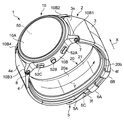
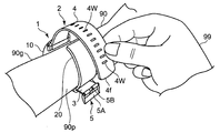
- FIG. 1 shows an external view of a blood pressure monitor of the embodiment (the whole is denoted by reference numeral 1) to which the blood pressure related information display device of the present invention is applied, as viewed obliquely with the belt 2 fastened. Yes.
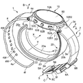
- FIG. 2 shows the appearance of the sphygmomanometer 1 as viewed obliquely with the belt 2 opened.
- the sphygmomanometer 1 is broadly divided into a main body 10 and a body to be measured (in this example, a left hand as a site to be measured as shown in FIG. 6C described later).
- the dimension in the width direction X of the belt 2 is set to 29 mm in this example. Further, the thickness of the belt 2 is set to 2 mm in this example.
- the main body 10 includes a substantially short cylindrical case 10B, a circular glass 10A attached to the upper part of the case 10B (in FIGS. 1 and 2), and a back cover attached to the lower part of the case 10B. (Not shown).
- a pair of left and right (in FIGS. 1 and 2) protruding lugs 10B1, 10B2; 10B3, 10B4 for attaching the belt 2 are integrally provided on the side surface of the case 10B.
- a display 50 that forms a display screen is provided in the glass 10A at the top of the case 10B.
- a measurement switch 52A for instructing the start or stop of blood pressure measurement and a display screen of the display 50 are returned to a predetermined home screen.
- Home switch 52B, and a recording call switch 52C for instructing display unit 50 to display past measurement records such as blood pressure and activity (these switches are collectively referred to as operation unit 52).
- a blood pressure measuring element including a pump 30 is mounted inside the main body 10 (described in detail later).
- the sphygmomanometer 1 includes functions of an activity meter and a pulse meter.
- the main body 10 is small and thin so as not to disturb the daily activities of the user.
- the belt 2 includes a belt-shaped first belt portion 3 extending from the main body 10 to one side in one direction (right side in FIG. 2) and the other side in one direction (in FIG. 2, And a belt-like second belt portion 4 extending to the left side).
- the base portion 3e on the side closer to the main body 10 of the first belt portion 3 is connected to the lugs 10B1 and 10B2 of the main body 10 via a connecting rod 7 (known spring rod) extending in the belt width direction X. As shown by a double arrow A, it is rotatably attached.
- a base portion 4e on the side closer to the main body 10 in the second belt portion 4 is connected to a lug 10B3, 10B4 of the main body 10 in a belt width direction X (a connecting rod 8 (known spring bar)). As shown by a double arrow B, it is rotatably attached.
- a buckle 5 is attached to the distal end portion 3 f of the first belt portion 3 on the side far from the main body 10.
- the buckle 5 is of a known type, and includes a substantially U-shaped frame-like body 5A, a stick 5B, and a connecting rod 5C extending in the belt width direction X.
- the frame-like body 5A and the stick 5B are attached to the tip 3f of the first belt portion 3 on the side far from the main body 10 so as to be rotatable as indicated by a double arrow C via the connecting rod 5C. ing.
- a ring shape is provided at a predetermined position in the longitudinal direction of the first belt portion 3 (corresponding to the circumferential direction Y of the left wrist 90).
- the belt holding portions 6A and 6B are integrally provided.
- the inner peripheral surface 3a of the first belt portion 3 does not protrude toward the inner peripheral side at the belt holding portions 6A and 6B, and is formed substantially flat (curved as a whole, but locally). . Thereby, it is intended that the belt 2 uniformly surrounds and restrains the outer peripheral side of the cuff structure 20.
- a plurality of small holes 4w, 4w,... Penetrate in the thickness direction of the second belt portion 4 between the root portion 4e of the second belt portion 4 and the tip portion 4f far from the main body 10. Is formed.
- a portion connected to the front end portion 4f of the second belt portion 4 is passed through the frame-like body 5A of the buckle 5, and a plurality of second belt portions 4 are provided.
- the first belt portion 3 and the second belt portion 4 constituting the belt 2 are flexible in the thickness direction and substantially in the longitudinal direction (corresponding to the circumferential direction Y of the left wrist 90). It is made of a plastic material that exhibits non-stretchability. Accordingly, the belt 2 can easily surround and restrain the outer peripheral side of the cuff structure 20 when being worn, and can also assist the compression of the left wrist 90 during blood pressure measurement described later.
- the 1st belt part 3 and the 2nd belt part 4 may consist of leather materials.
- the frame 5A and the stick 5B constituting the buckle 5 are made of a metal material in this example, but may be made of a plastic material.
- the cuff structure 20 includes a curler 24 disposed on the outermost periphery, a press cuff 23 disposed along the inner peripheral surface of the curler 24, and an inner peripheral surface of the press cuff 23.
- a back plate 22 as a reinforcing plate arranged along the back plate 22 and a sensing cuff 21 arranged along the inner peripheral surface of the back plate 22 are included.
- the curler 24, the pressing cuff 23, the back plate 22, and the sensing cuff 21 each have a strip shape that is elongated in one direction (Y direction).
- the sensing cuff 21 is configured in a bag shape.
- a fluid for pressure transmission (air in this example) is supplied to the sensing cuff 21 at the end on the base side (+ Y side) with respect to the longitudinal direction Y of the sensing cuff 21, or pressure transmission is performed from the sensing cuff 21.
- a flexible tube 38 (see FIG. 3) for discharging the fluid is attached.
- An inner peripheral surface 20 a of the cuff structure 20 is configured by a sensing cuff 21.
- the pressing cuff 23 is also configured in a bag shape.
- a pressure transmission fluid (in this example, air) is supplied to the pressure cuff 23 at an end portion on the base side (+ Y side) with respect to the longitudinal direction Y of the pressure cuff 23, or pressure transmission is performed from the pressure cuff 23.
- a flexible tube 39 (see FIG. 3) for discharging the fluid is attached.
- the pressing cuff 23 is inflated to press the left wrist 90 when it is supplied with a pressurizing fluid from the main body 10 side through the flexible tube 39 in the mounted state.
- the back plate 22 is made of a plate-like resin (in this example, polypropylene) having a thickness of about 1 mm in this example.
- the back plate 22 functions as a reinforcing plate and can transmit the pressing force from the pressing cuff 23 to the entire area in the longitudinal direction Y of the sensing cuff 21 (corresponding to the circumferential direction of the left wrist 90).
- the back plate 22 is provided with a plurality of V-shaped or U-shaped grooves (not shown) extending in the width direction X so as to be spaced apart from each other in the longitudinal direction Y in parallel. Thereby, the back board 22 becomes thin compared with another location in the location of a groove
- the cuff structure 20 is placed on the left wrist.
- the back plate 22 does not prevent the end plate 90 from bending along the circumferential direction Y.
- the curler 24 is made of a resin plate having a certain degree of flexibility and hardness (in this example, polypropylene) having a thickness of about 1 mm in this example.
- the curler 24 In the natural state, the curler 24 has a curved shape along the circumferential direction Y surrounding the left wrist 90. Thereby, the shape of the cuff structure 20 in the natural state is maintained in a curved state along the circumferential direction Y of the left wrist 90 as shown in FIG.
- One end 20f of the cuff structure 20 (the root portion of the curler 24) is attached to the main body 10.
- the other end 20e of the cuff structure 20 is a free end.
- the cuff structure 20 can be separated from the inner peripheral surfaces 3 a and 4 a of the belt 2.
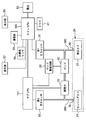
- FIG. 3 shows a block configuration of a control system of the sphygmomanometer 1.
- the main body 10 of the sphygmomanometer 1 includes a main CPU (Central Processing Unit) 100 as a control unit and a sub CPU 101 as blood pressure measurement elements for executing blood pressure measurement in addition to the display 50 and the operation unit 52 described above.
- a memory 51 as a storage unit, an acceleration sensor 54, a communication unit 59, a battery 53, a first pressure sensor 31 for detecting the pressure of the pressing cuff 23, and a second pressure sensor 32 for detecting the pressure of the sensing cuff 21.
- a pump 30, an on-off valve 33, and a pump drive circuit 35 for driving the pump 30 are mounted.
- the main CPU 100 mainly controls the entire operation of the sphygmomanometer 1, and the sub CPU 101 mainly controls the operation of the air system.
- the main CPU 100 and the sub CPU 101 are simply referred to as a CPU 100.
- the display 50 is an LCD (Liquid Cristal Display), and displays information related to blood pressure measurement such as a blood pressure measurement result and other information according to a control signal from the CPU 100.
- the display device 50 is not limited to an organic EL display, and may include another type of display device 50 such as an organic EL (Electro-Luminescence) display.
- the display device 50 may include an LED (Light (Emitting Diode). The configuration of the display screen of the display device 50 will be described later.
- the operation unit 52 includes a measurement switch 52A for instructing start or stop of blood pressure measurement, a home switch 52B for returning the display screen of the display 50 to a predetermined home screen, A recording call switch 52C for instructing the display 50 to display measurement records such as blood pressure and activity amount.
- these switches 52A to 52C are push-type switches, and input an operation signal in accordance with an instruction to start or stop blood pressure measurement by the user to the CPU 100.
- the operation unit 52 is not limited to a push-type switch, and may be, for example, a pressure-sensitive (resistance) or proximity (capacitance) touch panel switch.
- a microphone (not shown) may be provided, and a blood pressure measurement start instruction may be input by a user's voice.
- the memory 51 includes data of a program for controlling the sphygmomanometer 1, data used for controlling the sphygmomanometer 1, setting data for setting various functions of the sphygmomanometer 1, data of measurement results of the blood pressure value, etc. Is stored temporarily.
- the memory 51 is used as a work memory when the program is executed.
- the CPU100 performs various functions as a control part according to the program for controlling the blood pressure meter 1 memorize
- FIG. For example, when executing the blood pressure measurement function, the CPU 100, based on signals from the first pressure sensor 31 and the second pressure sensor 32, in response to an instruction to start blood pressure measurement from the measurement switch 52A of the operation unit 52, Control for driving the pump 30 and the on-off valve 33 is performed. Further, the CPU 100 performs control to calculate a blood pressure value, a pulse, and the like based on a signal from the second pressure sensor 32.
- the acceleration sensor 54 is composed of a three-axis acceleration sensor integrated in the main body 10.
- the acceleration sensor 54 outputs to the CPU 100 an acceleration signal representing the acceleration of the main body 10 in three directions orthogonal to each other.
- the output of the acceleration sensor 54 is used to measure the amount of activity.
- the communication unit 59 is controlled by the CPU 100 to transmit predetermined information to an external device via a network, or receives information from an external device via the network and passes it to the CPU 100. Communication via this network may be either wireless or wired.
- the network is the Internet, but is not limited to this, and may be another type of network such as an in-hospital LAN (Local Area Network), or a pair using a USB cable or the like. 1 communication may be sufficient.
- the communication unit 59 may include a micro USB connector.
- the battery 53 is a rechargeable secondary battery.
- the battery 53 is an element mounted on the main body 10, in this example, the CPU 100, the memory 51, the acceleration sensor 54, the communication unit 59, the first pressure sensor 31, the second pressure sensor 32, the pump 30, the on-off valve 33, and Electric power is supplied to each element of the pump drive circuit 35.
- the pump 30 is a piezoelectric pump in this example, and is driven by a pump driving circuit 35 based on a control signal given from the CPU 100.
- the pump 30 is connected to the pressing cuff 23 through the first flow path forming member 390 and the flexible tube 39 constituting the first flow path so that fluid can flow.
- the pump 30 can supply air as a pressurizing fluid to the pressing cuff 23 through the first flow path forming member 390 and the flexible tube 39.
- the pump 30 is equipped with an exhaust valve (not shown) that is controlled to open and close as the pump 30 is turned on / off.
- the exhaust valve closes when the pump 30 is turned on and helps to enclose air in the pressure cuff 23, while it opens when the pump 30 is turned off to allow the air in the pressure cuff 23 to be flexible.
- the gas is discharged into the atmosphere through the tube 39 and the first flow path forming member 390.
- the exhaust valve has a check valve function, and the exhausted air does not flow backward.
- the pump 30 is connected to the sensing cuff 21 through the second flow path forming member 380 constituting the second flow path and the flexible tube 38 so that fluid can flow.
- An open / close valve (in this example, a normally open electromagnetic valve) 33 is interposed in the second flow path (actually, between the first flow path forming member 390 and the second flow path forming member 380). It is inserted.
- the on-off valve 33 is controlled to open and close (opening) based on a control signal given from the CPU 100. When the on-off valve 33 is in an open state, air can be supplied from the pump 30 to the sensing cuff 21 through the second flow path as a pressure transmitting fluid and stored.
- the first pressure sensor 31 and the second pressure sensor 32 are each composed of a piezoresistive pressure sensor in this example.
- the first pressure sensor 31 detects the pressure in the pressing cuff 23 via the first flow path forming member 390 and the flexible tube 39 that constitute the first flow path.
- the second pressure sensor 32 detects the pressure in the sensing cuff 21 via the second flow path forming member 380 and the flexible tube 38 constituting the second flow path.
- the sphygmomanometer 1 is configured in a small and integrated manner by mounting the blood pressure measuring element as described above on the main body 10. Therefore, user convenience is good.
- FIG. 4 shows an operation flow when the blood pressure is measured by the sphygmomanometer 1 as a subject.
- the user wears the sphygmomanometer 1 on the left wrist 90 serving as a measurement site.
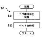
- the user wears the cuff structure 20 on the left wrist 90 using the right hand 99 (step S21 in FIG. 5).
- the user places the main body 10 of the sphygmomanometer 1 on the back side surface (the back side surface) 90 g of the left wrist 90.
- the cuff structure 20 is curved along the circumferential direction Y of the left wrist 90 by the curler 24 in a natural state.
- the user fits the cuff structure 20 on the outer peripheral surface of the left wrist 90 using the right half body hand (in this example, the right hand 99) opposite to the left half body to which the left wrist 90 belongs.
- the cuff structure 20 can be easily attached to the left wrist 90. In a state where the cuff structure 20 is attached to the left wrist 90, even if the user releases the right hand 99 from the cuff structure 20, the cuff structure 20 grips the left wrist 90.
- the body 20 (and the belt 2, the main body 10) is difficult to drop off.
- the user uses the right hand 99 to bring the belt 2 around the left wrist 90 and the cuff structure 20 together.
- a portion connected to the front end portion 4f of the second belt portion 4 is passed through the frame-like body 5A of the buckle 5 of the first belt portion 3, and a plurality of small holes 4w, 4w,.
- a stick 5B with a buckle 5 is inserted into any one of the above.
- the 1st belt part 3 and the 2nd belt part 4 are fastened (step S22 in FIG. 5).
- the belt 2 extending from the main body 10 surrounds the left wrist 90, and the band-shaped cuff structure 20 having one end 20 f attached to the main body 10 is arranged closer to the left wrist 90 than the belt 2. It becomes a state.
- the cuff structure 20 can be separated from the inner peripheral surfaces 3a and 4a of the belt 2, and the other end 20e on the side opposite to the one end 20f of the cuff structure 20 is a free end. ing. Accordingly, when the first belt portion 3 and the second belt portion 4 are fastened, the cuff structure 20 receives an inward force from the belt 2 and just follows the outer peripheral surface of the left wrist 90. 20 can slide or deform. Thereby, in the wearing state, the cuff structure 20 and the belt 2 are in close contact with the outer peripheral surface of the left wrist 90 in this order, that is, the left wrist 90 is surrounded as a whole in a band shape. In this manner, the sphygmomanometer 1 can be easily attached to the left wrist 90.
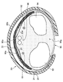
- the bag-shaped pressing cuff 23 extends along the circumferential direction Y of the left wrist 90 on the inner peripheral side of the curler 24 included in the cuff structure 20.
- the bag-shaped sensing cuff 21 included in the cuff structure 20 is disposed on the inner peripheral side with respect to the pressing cuff 23 and is in contact with the palm side surface (the surface on the palm side) 90p of the left wrist 90, and the left wrist. It extends in the circumferential direction Y so as to cross 90 arterial passage portions 90a.
- a back plate 22 included in the cuff structure 20 is inserted between the pressing cuff 23 and the sensing cuff 21 and extends along the circumferential direction Y of the left wrist 90.
- the main body 10 and the belt 2 are not shown.
- the radius 93, ulna 94, radial artery 91, ulnar artery 92, and tendon 96 of the left wrist 90 are shown.
- step S2 in FIG. 4 when the user presses the measurement switch 52A of the operation unit 52 provided in the main body 10 (step S2 in FIG. 4), the CPU 100 initializes the processing memory area (step S3 in FIG. 4). In addition, the CPU 100 turns off the pump 30 via the pump drive circuit 35, opens the exhaust valve built in the pump 30, and maintains the on-off valve 33 in the open state so that the inside of the pressing cuff 23 and the sensing cuff 21 Exhaust the air. Subsequently, the control for adjusting 0 mmHg of the first pressure sensor 31 and the second pressure sensor 32 is performed.
- the CPU 100 operates as a pressurization control unit and a fluid accommodation control unit, turns on the pump 30 via the pump drive circuit 35 (step S4 in FIG. 4), maintains the on-off valve 33 in the open state, and presses it.
- Pressurization of the cuff 23 and the sensing cuff 21 is started (step S5 in FIG. 4).
- the pump 30 is driven via the pump drive circuit 35 while monitoring the pressure of the pressure cuff 23 and the sensing cuff 21 by the first pressure sensor 31 and the second pressure sensor 32, respectively.
- the first flow path (the first flow path forming member 390 and the flexible tube 39) is passed through the pressing cuff 23, and the second flow path (the second flow path forming member 380 and the flexible tube 39 is flexible). Control is performed to send air to the sensing cuff 21 through the tube 38).
- step S6 of FIG. 4 the CPU 100 functions as a fluid accommodation control unit, and the pressure of the sensing cuff 21 has reached a predetermined pressure (15 mmHg in this example) or the driving time of the pump 30 is predetermined. It is determined whether or not only the time (3 seconds in this example) has elapsed. The reason for making this determination is to confirm whether or not an appropriate amount of air is contained in the sensing cuff 21. If NO in step S6 of FIG. 4, the process waits until the pressure of the sensing cuff 21 reaches a predetermined pressure or until the driving time of the pump 30 has elapsed for a predetermined time. It should be noted that the amount of “appropriate amount” of the pressure transmission fluid stored in the sensing cuff 21 is set in advance by experiments.
- step S6 of FIG. 4 it is determined that an appropriate amount of air is contained in the sensing cuff 21.
- step S7 of FIG. 4 the CPU 100 operates as a pressurization control unit, keeps the on-off valve 33 in the closed state, and continues the control of supplying air from the pump 30 to the pressing cuff 23 through the first flow path.
- the pressure cuff 23 is expanded and the pressure is gradually increased to press the left wrist 90.
- the back plate 22 transmits the pressing force from the pressing cuff 23 to the sensing cuff 21.
- the sensing cuff 21 presses the left wrist 90 (including the artery passage portion 90a).
- the CPU 100 monitors the pressure of the sensing cuff 21, that is, the pressure of the arterial passage portion 90a of the left wrist 90 with the second pressure sensor 32 in order to calculate the blood pressure value. Acquire a pulse wave signal.
- step S8 of FIG. 4 the CPU 100 operates as a blood pressure calculation unit, and applies a known algorithm by an oscillometric method based on the pulse wave signal acquired at this time, and applies a blood pressure value (systolic blood pressure). Attempts to calculate SBP and diastolic blood pressure DBP).
- the cuff pressure has reached the upper limit pressure (for example, 300 mmHg is determined in advance for safety). Unless otherwise specified, the processes in steps S7 to S9 are repeated.
- step S9 the CPU 100 stops the pump 30 (step S10), opens the on-off valve 33 (step S11), and within the press cuff 23, the sensing cuff 21. Control to exhaust the air inside. Finally, the measurement result of the blood pressure value is displayed on the display device 50 (step S12). In addition, the process which displays a measurement result on the display screen of the indicator 50 is mentioned later.
- the blood pressure calculation may be performed not in the pressurizing process of the pressing cuff 23 but in the depressurizing process.
- the second pressure sensor 32 is separate from the pressure cuff 23, that is, the pressure of the sensing cuff 21, that is, the left wrist 90.
- the pressure of the arterial passage portion 90a is detected. Therefore, as a result of setting the dimension in the width direction X of the belt 2 and the cuff structure 20 (simply referred to as “cuff” where appropriate) to a small size (for example, about 25 mm), the pressure cuff 23 is moved in the thickness direction during pressurization. Even in the case where compression loss occurs due to large expansion, blood pressure can be measured with high accuracy.
- the sensing cuff 21 extends in the circumferential direction Y so as to cross the arterial passage portion 90 a of the left wrist 90. Accordingly, when the user actually wears the sphygmomanometer 1 on the left wrist 90, even if the cuff is displaced to some extent with the main body 10 in the circumferential direction Y of the left wrist 90, the arteries passing portion 90a of the left wrist 90 The sensing cuff 21 does not come off. Therefore, it is possible to prevent the blood pressure measurement value from varying from the actual blood pressure, and as a result, the blood pressure can be measured with high accuracy.
- the sensing cuff 21 may contain a fluid for pressure transmission and may be sealed.
- the CPU 100 calculates and acquires the pulse (number of times per minute) (/ min) of the subject in addition to the blood pressure value based on the above-described pulse wave signal.
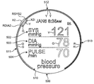
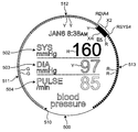
- FIG. 11 illustrates the configuration of the display screen 500 of the display device 50.
- the display screen 500 has a circular outline.
- the current date and time in this example, January 6th, 8:38 am, “JAN6” in this order from the top to the bottom.
- 8:38 AM " a systolic blood pressure display area 502 for digitally displaying systolic blood pressure (maximum blood pressure; SYS) in mmHg units, and a diastolic blood pressure (minimum blood pressure) in mmHg units.
- PULSE pulses
- a title display area 505 for indicating In the left half of the systolic blood pressure display area 502, the left half of the diastolic blood pressure display area 503, and the left half of the pulse display area 504, character strings “SYS mmHg”, “DIA mmHg”, “DIA mmHg”, “ “PULSE / min” is displayed.
- digital values “110”, “78”, and “70” are respectively displayed in the right half of the systolic blood pressure display area 502, the right half of the diastolic blood pressure display area 503, and the right half of the pulse display area 504. It is displayed.
- the ground color BK of the inner region 500a is white or black.
- an arc-shaped area (area having a scale) 510 along the annular peripheral edge 500p is set as a curved and elongated display area forming one-dimensional risk coordinates.
- the arcuate region 510 is divided into a plurality of stages along the arc according to a predetermined blood pressure standard, in this example, three stages from a first risk stage 511 to a third risk stage 513.
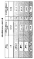
- the classification (hereinafter referred to as “AHA classification”) published by the American Heart Association (AHA) as shown in FIG. 9 is used as the blood pressure standard.
- the first risk stage 511 corresponds to the “normal” category of the AHA classification.
- the second risk stage 512 includes the AHA classification “prehypertension” and “hypertension stage 1”.
- the third risk stage 513 includes the AHA classification “hypertension stage 2” and “hypertensive crisis”.
- the AHA classification “normal” category is a case where the systolic blood pressure (maximum blood pressure) is less than 120 mmHg and the diastolic blood pressure (minimum blood pressure) is less than 80 mmHg.
- Prehypertension is considered to be when the systolic blood pressure is 120 mmHg-139 mmHg or the diastolic blood pressure is 80 mmHg-89 mmHg.
- “High blood pressure stage 1” is a case where the systolic blood pressure is 140 mmHg-159 mmHg or the diastolic blood pressure is 90 mmHg-99 mmHg.
- “High blood pressure stage 2” is a case where the systolic blood pressure is 160 mmHg or more or the diastolic blood pressure is 100 mmHg or more.
- “Hypertensive emergency” is considered to be a case where systolic blood pressure exceeds 180 mmHg or diastolic blood pressure exceeds 110 mmHg.
- a plurality of substantially rectangular scales 511i, 511i,... With green G are arranged at a constant pitch along the peripheral edge 500p of the display screen 500. They are arranged side by side. There is a gap between a certain scale 511i and the adjacent scale 511i, and the ground color BK of the display screen 500 is visible.
- the second risk stage 512 of the arcuate region 510 is configured by arranging a plurality of substantially rectangular scales 512i, 512i,... With yellow Y arranged at a constant pitch along the peripheral edge 500p of the display screen 500. .
- the first risk stage 511 there is a gap between a certain scale 512i and the adjacent scale 512i, and the ground color BK of the display screen 500 is visible.
- the third risk stage 513 of the arcuate region 510 is configured by arranging a plurality of substantially rectangular scales 512i, 513i,... With a red R along the peripheral edge 500p of the display screen 500 at a constant pitch. .
- a gap exists between a certain scale 513i and the adjacent scale 513i, and the ground color BK of the display screen 500 is visible. .
- the green G, yellow Y, and red R in the three risk stages 511 to 513 from the first to the third are set as colors that intuitively represent the meanings of safety (or relief), caution, and warning, respectively.
- FIG. 8 shows a flow of processing for displaying a measurement result on the display screen 500 of the display 50 as a blood pressure related information display method according to an embodiment.
- the CPU 100 functions as a data acquisition unit, and acquires blood pressure data including systolic blood pressure and diastolic blood pressure for a user (here, a subject). This process corresponds to the blood pressure measurement process shown in FIG.
- step S32 of FIG. 8 the CPU 100 works as a risk value calculation unit, and based on the AHA classification, the systolic risk value representing the risk according to the acquired systolic blood pressure, and the acquired expansion A diastolic risk value representing a risk corresponding to the systolic blood pressure is obtained.
- risk values from 0 to 6.0 are associated with each of the acquired systolic blood pressure SYS and the acquired diastolic blood pressure DIA in this example.
- the systolic risk value is made to correspond to 1.5 (indicated by the symbol RSYS1).
- the acquired diastolic blood pressure DIA is 78, 1.8 (indicated by the sign RDIA1) is made to correspond to the diastolic risk value.
- the systolic blood pressure SYS is less than 80 mmHg, 0 is made to correspond to the systolic risk value. If the systolic blood pressure SYS is 100 mmHg, 1.0 is made to correspond to the systolic risk value. If the systolic blood pressure SYS is 120 mmHg, 2.0 is made to correspond to the systolic risk value. If the systolic blood pressure SYS is 140 mmHg, 3.0 is made to correspond to the systolic risk value. If the systolic blood pressure SYS is 160 mmHg, 4.0 is made to correspond to the systolic risk value.
- the systolic blood pressure SYS is 180 mmHg, 5.0 is made to correspond to the systolic risk value. If the systolic blood pressure SYS is 200 mmHg or more, 6.0 is made to correspond to the systolic risk value. That is, the systolic risk value is increased by 1 as the systolic blood pressure SYS increases by 20 mmHg. Further, within the range of 20 mmHg of each systolic blood pressure SYS, the systolic risk value is increased by 0.1 as the systolic blood pressure SYS increases by 2 mmHg.
- the diastolic blood pressure DIA is less than 60 mmHg, 0 is made to correspond to the diastolic risk value. If the diastolic blood pressure DIA is 70 mmHg, 1.0 is associated with the diastolic risk value. If the diastolic blood pressure DIA is 80 mmHg, 2.0 is made to correspond to the diastolic risk value. If the diastolic blood pressure DIA is 90 mmHg, 3.0 is associated with the diastolic risk value. If the diastolic blood pressure DIA is 100 mmHg, 4.0 is associated with the diastolic risk value.
- the diastolic blood pressure DIA is 110 mmHg, 5.0 is associated with the diastolic risk value. If the diastolic blood pressure DIA is 120 mmHg or more, 6.0 is made to correspond to the diastolic risk value. That is, the diastolic risk value is increased by 1 as the diastolic blood pressure DIA increases by 10 mmHg. Also, within each 10 mmHg range of the diastolic blood pressure DIA, the diastolic risk value is increased by 0.1 as the diastolic blood pressure DIA increases by 1 mmHg.
- the risk value when the risk value is 0 to 1.9, it belongs to the first risk stage 511 marked with green G in FIG. Belongs to the second risk stage 512 marked with yellow Y in FIG. 11, and the risk value is 4.0 to 6.0 in FIG. Belonging to the third risk stage 513 marked with red R.
- step S33 of FIG. 8 the CPU 100 works as a display processing unit, and the risk range from the systolic risk value to the diastolic risk value is displayed on the arcuate area 510 along the peripheral edge 500p on the display screen 500.
- Process to display Thereby, on the display screen 500, a continuous band-like area as described below is displayed as the risk range.
- the systolic risk value is represented as RSYS1, RSYS2,...
- the diastolic risk value is represented as RDIA1, RDIA2,.
- step S33 of FIG. 8 in order to indicate the risk range X1 from the systolic risk value RSYS1 to the diastolic risk value RDIA1, a continuous band-shaped area is formed in the arc-shaped area 510. X1i is displayed.
- the band-shaped region X1i is wider than the range other than the risk range X1 in the arc-shaped region 510, and is thereby highlighted. Therefore, the user can intuitively recognize the risk range X1 in the arc-shaped region 510.
- the systolic risk value RSYS1 and the diastolic risk value RDIA1 both belong to the first risk stage 511, and the entire risk range X1 is included in the first risk stage 511. Accordingly, green G is added to the entire area of the belt-like region X1i. Therefore, the user can intuitively recognize the risk stage of blood pressure.
- step S33 of FIG. 8 as shown in FIG. 12, in order to show the risk range X2 from the systolic risk value RSYS2 to the diastolic risk value RDIA2, a continuous belt-like region X2i is displayed.
- the band-shaped area X2i is wider than the risk area X2 in the arc-shaped area 510 and is highlighted. Therefore, the user can intuitively recognize the risk range X2 in the arc-shaped region 510.
- the systolic risk value RSYS2 belongs to the second risk stage 512
- the diastolic risk value RDIA2 belongs to the first risk stage 511
- the risk range X2 is the first risk stage 511. It straddles two stages with a second risk stage 512. Accordingly, the belt-like region X2i is color-coded into green G and yellow Y. Therefore, the user can intuitively recognize the risk stage of blood pressure.
- step S33 of FIG. 8 as shown in FIG. 13, in order to indicate the risk range X3 from the systolic risk value RSYS3 to the diastolic risk value RDIA3, a continuous band-shaped area is formed in the arc-shaped area 510. X3i is displayed.
- the band-shaped area X3i is wider than the risk area X3 in the arc-shaped area 510, and is highlighted in the same manner as the band-shaped areas X1i and X2i. Therefore, the user can intuitively recognize the risk range X3 in the arc-shaped region 510.
- the systolic risk value RSYS3 and the diastolic risk value RDIA3 both belong to the second risk stage 512, and the entire risk range X3 is included in the second risk stage 512. Accordingly, yellow Y is given to the entire band-like region X3i. Therefore, the user can intuitively recognize the risk stage of blood pressure.
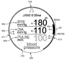
- step S33 of FIG. 8 in order to indicate the risk range X4 from the systolic risk value RSYS4 to the diastolic risk value RDIA4, a continuous band-shaped region is formed in the arc-shaped region 510. X4i is displayed.
- the band-like region X4i is wider than the range other than the risk range X4 in the arc-like region 510, and is highlighted by the same as the band-like regions X1i to X3i. Therefore, the user can intuitively recognize the risk range X4 in the arc-shaped region 510.
- the systolic risk value RSYS4 belongs to the third risk stage 513
- the diastolic risk value RDIA4 belongs to the second risk stage 512
- the risk range X4 is the second risk stage 512. It straddles two stages with a third risk stage 513. Accordingly, the belt-like region X4i is color-coded into yellow Y and red R. Therefore, the user can intuitively recognize the risk stage of blood pressure.
- step S33 of FIG. 8 as shown in FIG. 15, in order to indicate the risk range X5 from the systolic risk value RSYS5 to the diastolic risk value RDIA5, X5i is displayed.
- the band-like region X5i is wider than the range other than the risk range X5 in the arc-like region 510, and is highlighted by the same as the band-like regions X1i to X4i. Therefore, the user can intuitively recognize the risk range X5 in the arc-shaped region 510.
- both the systolic risk value RSYS5 and the diastolic risk value RDIA5 belong to the third risk stage 513, and the entire risk range X5 is included in the third risk stage 513. Accordingly, red R is given to the entire band-like region X5i. Therefore, the user can intuitively recognize the risk stage of blood pressure.
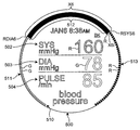
- step S33 of FIG. 8 in order to indicate the risk range X6 from the systolic risk value RSYS6 to the diastolic risk value RDIA6, a continuous band-shaped area is formed in the arc-shaped area 510. X6i is displayed.
- the band-shaped area X6i is wider than the area other than the risk range X6 in the arc-shaped area 510, and is highlighted in the same manner as the band-shaped areas X1i to X5i. Therefore, the user can intuitively recognize the risk range X6 in the arc-shaped region 510.
- the risk range X6 is changed from the first risk stage 511 to the third risk stage 511. There are three stages up to risk stage 513.
- the highest risk stage in this example, the third risk stage in the risk range X6. 513) (the red color in this example) is assigned.
- the belt-like region X6i is color-coded into green G and red R. Therefore, the user can strongly recognize that the risk range X6 extends over the highest risk level (in this example, the third risk level 513).
- the arc-shaped area 510 is a curved and elongated display area, so that information related to the user's blood pressure can be displayed in a display area with a small area. Further, the user can intuitively recognize the risk range of blood pressure by looking at the position of the risk range displayed in the arc-shaped region 510.
- the CPU 100 works as a display processing unit, performs the processing of step S34 of FIG. 8 in parallel with the processing of steps S31 to S33 of FIG. 8, and in the internal region 500a surrounded by the arc-shaped region 510.
- the acquired systolic blood pressure is digitally displayed in the systolic blood pressure display area 502, and the acquired diastolic blood pressure is digitally displayed in the diastolic blood pressure display area 503.
- the acquired pulse (/ min) is digitally displayed in the pulse display area 504. Therefore, the user can know the digital values representing the systolic blood pressure, the diastolic blood pressure, and the pulse by looking at the internal region 500a.
- the digital display of the systolic blood pressure, the digital display of the diastolic blood pressure, and the like are made in the internal region 500a surrounded by the arc-shaped region 510 in the display screen 500, the area of the display screen 500 is effectively utilized.
- the systolic blood pressure display area 502 the digital display of the systolic blood pressure in the diastolic blood pressure display area 503, and the digital display of the diastolic blood pressure have respective systolic blood pressures. Colors are assigned according to the risk stages 511 to 513 to which the diastolic blood pressure belongs. For example, the digital display of systolic blood pressure in the systolic blood pressure display area 502 and the digital display of diastolic blood pressure in the diastolic blood pressure display area 503 in FIG. The digital display of systolic blood pressure in the systolic blood pressure display area 502 in FIG.
- the digital display of systolic blood pressure in the systolic blood pressure display area 502 in FIG. 14 and the digital display of diastolic blood pressure in the diastolic blood pressure display area 503 are marked with red R and yellow Y, respectively.
- the digital display of systolic blood pressure in the systolic blood pressure display area 502 in FIG. 16 and the digital display of diastolic blood pressure in the diastolic blood pressure display area 503 are marked with red R and green G, respectively.
- the user looks at the digital display colors in the systolic blood pressure display area 502 and the diastolic blood pressure display area 503 to thereby determine the systolic risk value and the diastolic risk value that define the respective risk ranges X1 to X6. Of these, it is easy to recognize which risk value is high (or low).
- the risk ranges X1 to X6 are displayed as continuous band-shaped areas, but the present invention is not limited to this.
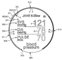
- the risk range X7 may be displayed as two marks separated from each other, a mark X7j representing a systolic risk value and a mark X7i representing a diastolic risk value.
- the acquired systolic blood pressure SYS is 121 mmHg
- the acquired diastolic blood pressure DIA is 78 mmHg in step S31 of FIG. In this case, in step S32 of FIG.
- the contraction is performed on the inner peripheral side of the arcuate region 510.
- a mark X7j indicating a period risk value and a mark X7i indicating a diastole risk value are displayed. Therefore, the user can intuitively recognize the risk range X7 in the arc-shaped region 510.
- the systolic risk value RSYS7 belongs to the second risk stage 512
- the diastolic risk value RDIA7 belongs to the first risk stage 511. Accordingly, a yellow mark Y is attached to the mark X7j of ⁇ representing the systolic risk value, and a green mark G is attached to the mark X7i of the ⁇ mark representing the diastolic risk value. Therefore, the user can intuitively recognize the risk stage of blood pressure.
- the display screen 500 is circular, and the risk ranges X1 to X7 are displayed in the arc-shaped area 510 along the annular peripheral edge 500p.
- the present invention is not limited to this.
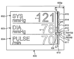
- the display screen 600 has a rectangular shape, and a column as an elongate display area of a straight line forming a one-dimensional risk coordinate along the edge 600p of one side (in this example, the right side).
- An area 610 may be provided.
- a systolic blood pressure display area 602, a diastolic blood pressure display area 603, and a pulse display area 604 are provided on the left side of the column area 610, which occupies most of the display screen 600.
- These systolic blood pressure display area 602, diastolic blood pressure display area 603, and pulse display area 604 correspond to the systolic blood pressure display area 502, diastolic blood pressure display area 503, and pulse display area 504 in FIGS. To do.
- the column area 610 is divided into five stages from a first risk stage 611 to a fifth risk stage 615 based on the AHA classification.
- the first risk stage 611 corresponds to the “normal” category of the AHA classification.
- the second risk stage 612 corresponds to the “prehypertension” of the AHA classification.
- the third risk stage 613 corresponds to “hypertension stage 1” of the AHA classification.
- the fourth risk stage 614 corresponds to “hypertension stage 2” of the AHA classification.
- the fifth risk stage 615 corresponds to the AHA classification “hypertensive crisis”.
- risk values from 0 to 6.0 correspond to the acquired systolic blood pressure SYS and the acquired diastolic blood pressure DIA in this example. Is done.
- a continuous band-shaped area X8i is displayed as the risk range from the systolic risk value to the diastolic risk value, as shown in FIGS.
- the acquired systolic blood pressure SYS is 121 mmHg and the acquired diastolic blood pressure DIA is 78 mmHg in step S31 of FIG.
- step S33 of FIG. 8 as shown in FIG.
- a continuous band-like region X8i is displayed in the column region 610. Is displayed.
- the band-like region X8i is wider than the range other than the risk range X8 in the column region 610, and is highlighted in the same manner as the band-like regions X1i to X6i. Therefore, the user can intuitively recognize the risk range X8 in the column region 610.
- the systolic risk value RSYS8 belongs to the second risk stage 612
- the diastolic risk value RDIA8 belongs to the first risk stage 611
- the risk range X8 is the first risk stage 611. It straddles two stages with a second risk stage 612. Accordingly, the belt-like region X8i is color-coded into green G and yellow Y. Therefore, the user can intuitively recognize the risk stage of blood pressure.
- the third risk stage 613 to the fifth risk stage 615 are given colors that intuitively indicate that the degree of warning increases sequentially, such as orange OR to red R, respectively.
- the user intuitively determines the risk range of blood pressure by looking at the position of the risk range X8 displayed in the column region 610. Can be recognized.
- each of the acquired systolic blood pressure SYS and the acquired diastolic blood pressure DIA is associated with a risk value of 0 to 6.0 in this example, but this is not limitative. It is not a thing.
- the risk value is merely interposed to associate the acquired systolic blood pressure SYS and the acquired diastolic blood pressure DIA with the display position of the risk range in the arc-shaped region 510 or the column region 610.
- a value of another scale such as 0 to 100 may be used.
- the display area (the arc-shaped area 510 and the column area 610) forming the one-dimensional risk coordinates is divided into three or five risk stages, but the present invention is not limited to this.
- the display area may be divided into two stages, four stages, or six stages or more. Further, the display area may be divided into one stage without being divided.
- the color given to each step is not limited to the above-described green G, yellow Y, red R, and the like, and may be various colors.
- the band-shaped areas X1i to X6i, X8i indicating the risk range are set as ranges other than the risk range (others).
- the range was highlighted to be wider than the range.
- the highlighting is not limited to this.
- the risk range may be highlighted by displaying it more brightly, displaying it more vividly, or blinking it, compared to a range other than the risk range.
- the display screen has a circular shape (display screen 500) or a rectangular shape (display screen 600), but is not limited thereto.
- the shape of the display screen may be various shapes such as a hexagon, an octagon, or a shape in which a part of a circle is notched flat.
- a display area (arc-shaped area 510, column area 610) for displaying a risk range and a display area (systolic blood pressure) for digitally displaying systolic blood pressure, diastolic blood pressure, and the like are displayed on the display screen.
- Display areas 502 and 602, diastolic blood pressure display areas 503 and 603, etc.) are provided together, but the present invention is not limited to this. Only a display area for displaying the risk range may be provided in the display screen.
- blood pressure data including the systolic blood pressure and the diastolic blood pressure of the subject is displayed on the display screen of the display device 50 so as to display the blood pressure risk.
- An example of obtaining by measuring with a measurement element has been described.
- the present invention is not limited to this.
- blood pressure data including the systolic blood pressure and the diastolic blood pressure of the subject is input from the outside of the sphygmomanometer 1 via the communication unit 59, and the blood pressure risk display is displayed on the display screen of the display 50 based on the blood pressure data. You may go.
- blood pressure data including the systolic blood pressure and the diastolic blood pressure measured by the blood pressure measurement element mounted on the main body 10 of the sphygmomanometer 1 is substantially transmitted to the external smartphone or the like via the communication unit 59.
- the blood pressure risk may be displayed on the display screen of the computer device by outputting to the computer device and causing the computer device to execute the above-described blood pressure related information display method.
- a program for causing a computer to execute the blood pressure related information display method is non-transitory on a computer-readable recording medium such as a flexible disk attached to a computer, a CD-ROM (Compact Disk-Read Memory), a ROM, a RAM, and a memory card. It can also be recorded and provided as a program product. Alternatively, the program can be provided by non-temporarily recording on a recording medium such as a hard disk built in the computer. A program can also be provided by downloading via a network.
Landscapes
- Health & Medical Sciences (AREA)
- Life Sciences & Earth Sciences (AREA)
- Engineering & Computer Science (AREA)
- Surgery (AREA)
- General Health & Medical Sciences (AREA)
- Biophysics (AREA)
- Pathology (AREA)
- Veterinary Medicine (AREA)
- Biomedical Technology (AREA)
- Heart & Thoracic Surgery (AREA)
- Medical Informatics (AREA)
- Molecular Biology (AREA)
- Public Health (AREA)
- Animal Behavior & Ethology (AREA)
- Physics & Mathematics (AREA)
- Cardiology (AREA)
- Vascular Medicine (AREA)
- Physiology (AREA)
- Nuclear Medicine, Radiotherapy & Molecular Imaging (AREA)
- Radiology & Medical Imaging (AREA)
- Ophthalmology & Optometry (AREA)
- Artificial Intelligence (AREA)
- Computer Vision & Pattern Recognition (AREA)
- Psychiatry (AREA)
- Signal Processing (AREA)
- Dentistry (AREA)
- Measuring Pulse, Heart Rate, Blood Pressure Or Blood Flow (AREA)
Priority Applications (3)
| Application Number | Priority Date | Filing Date | Title |
|---|---|---|---|
| CN201780080642.9A CN110113993B (zh) | 2016-12-28 | 2017-11-27 | 血压关联信息显示装置、血压关联信息显示方法以及程序 |
| DE112017006626.3T DE112017006626T5 (de) | 2016-12-28 | 2017-11-27 | Einrichtung für das anzeigen blutdruckbezogener information, verfahren für das anzeigen blutdruckbezogener information und programm |
| US16/454,745 US11647965B2 (en) | 2016-12-28 | 2019-06-27 | Blood-pressure-related information display device, blood-pressure-related information display method, and non-transitory computer readable medium |
Applications Claiming Priority (2)
| Application Number | Priority Date | Filing Date | Title |
|---|---|---|---|
| JP2016-256035 | 2016-12-28 | ||
| JP2016256035A JP6734773B2 (ja) | 2016-12-28 | 2016-12-28 | 血圧関連情報表示装置、血圧関連情報表示方法およびプログラム |
Related Child Applications (1)
| Application Number | Title | Priority Date | Filing Date |
|---|---|---|---|
| US16/454,745 Continuation US11647965B2 (en) | 2016-12-28 | 2019-06-27 | Blood-pressure-related information display device, blood-pressure-related information display method, and non-transitory computer readable medium |
Publications (1)
| Publication Number | Publication Date |
|---|---|
| WO2018123386A1 true WO2018123386A1 (ja) | 2018-07-05 |
Family
ID=62708161
Family Applications (1)
| Application Number | Title | Priority Date | Filing Date |
|---|---|---|---|
| PCT/JP2017/042371 Ceased WO2018123386A1 (ja) | 2016-12-28 | 2017-11-27 | 血圧関連情報表示装置、血圧関連情報表示方法およびプログラム |
Country Status (5)
| Country | Link |
|---|---|
| US (1) | US11647965B2 (enExample) |
| JP (1) | JP6734773B2 (enExample) |
| CN (1) | CN110113993B (enExample) |
| DE (1) | DE112017006626T5 (enExample) |
| WO (1) | WO2018123386A1 (enExample) |
Cited By (1)
| Publication number | Priority date | Publication date | Assignee | Title |
|---|---|---|---|---|
| CN113164085A (zh) * | 2018-12-27 | 2021-07-23 | 欧姆龙健康医疗事业株式会社 | 血压测定装置 |
Families Citing this family (4)
| Publication number | Priority date | Publication date | Assignee | Title |
|---|---|---|---|---|
| KR102407094B1 (ko) * | 2017-07-25 | 2022-06-08 | 삼성전자주식회사 | 생체정보 측정 장치 및 방법 |
| US10966664B2 (en) * | 2018-07-10 | 2021-04-06 | Kayden Beibei Fu | Dynamically calibrated blood pressure reference value electronic sphygmomanometer |
| CN115137327A (zh) * | 2021-03-31 | 2022-10-04 | 华为技术有限公司 | 一种血压测量方法及装置 |
| JP7632678B2 (ja) | 2021-10-27 | 2025-02-19 | オムロンヘルスケア株式会社 | 血圧関連情報表示装置 |
Citations (3)
| Publication number | Priority date | Publication date | Assignee | Title |
|---|---|---|---|---|
| JPS62197304U (enExample) * | 1987-06-11 | 1987-12-15 | ||
| JP2006122144A (ja) * | 2004-10-26 | 2006-05-18 | Matsushita Electric Works Ltd | 血圧測定装置 |
| JP2010119446A (ja) * | 2008-11-17 | 2010-06-03 | Omron Healthcare Co Ltd | 血圧測定装置 |
Family Cites Families (15)
| Publication number | Priority date | Publication date | Assignee | Title |
|---|---|---|---|---|
| JPS60132538A (ja) * | 1983-12-20 | 1985-07-15 | 松下電工株式会社 | 血圧計 |
| JPS6419406U (enExample) | 1987-07-21 | 1989-01-31 | ||
| JP4810149B2 (ja) * | 2005-07-21 | 2011-11-09 | 株式会社Icst | 血圧値表示装置、血圧計測装置、血圧値表示方法 |
| CN101317755A (zh) * | 2007-06-08 | 2008-12-10 | 曹德森 | 柯氏音听诊法血压测量装置及其数据处理方法 |
| JP2009219829A (ja) * | 2008-03-19 | 2009-10-01 | Terumo Corp | バイタルデータの表示装置及び制御方法 |
| CN101554322B (zh) * | 2008-04-09 | 2012-07-04 | 陈敦金 | 产科危重症患者病情评估系统 |
| US9778079B1 (en) * | 2011-10-27 | 2017-10-03 | Masimo Corporation | Physiological monitor gauge panel |
| US9480435B2 (en) * | 2012-02-09 | 2016-11-01 | Masimo Corporation | Configurable patient monitoring system |
| US9232894B2 (en) * | 2012-08-27 | 2016-01-12 | Koninklijke Philips N.V. | Remote patient management system |
| US9875560B2 (en) * | 2013-11-15 | 2018-01-23 | Shenzhen Mindray Bio-Medical Electronics Co., Ltd. | Graphical display of physiological parameters on patient monitors |
| US10580173B2 (en) * | 2013-11-15 | 2020-03-03 | Shenzhen Mindray Bio-Medical Electronics Co., Ltd. | Graphical display of physiological parameters on patient monitors |
| JP6331384B2 (ja) * | 2013-12-26 | 2018-05-30 | オムロンヘルスケア株式会社 | 活動量関連情報表示装置 |
| CN104970778A (zh) * | 2014-04-13 | 2015-10-14 | 唐伟钊 | 一种具有预警癌症和疾病功能的电子仪器 |
| CN107405088B (zh) * | 2015-02-24 | 2021-08-24 | 皇家飞利浦有限公司 | 用于为血压测量设备提供控制信号的装置和方法 |
| EP3334334B1 (en) * | 2015-08-11 | 2025-04-16 | Masimo Corporation | Medical monitoring analysis and replay including indicia responsive to light attenuated by body tissue |
-
2016
- 2016-12-28 JP JP2016256035A patent/JP6734773B2/ja active Active
-
2017
- 2017-11-27 WO PCT/JP2017/042371 patent/WO2018123386A1/ja not_active Ceased
- 2017-11-27 DE DE112017006626.3T patent/DE112017006626T5/de active Pending
- 2017-11-27 CN CN201780080642.9A patent/CN110113993B/zh active Active
-
2019
- 2019-06-27 US US16/454,745 patent/US11647965B2/en active Active
Patent Citations (3)
| Publication number | Priority date | Publication date | Assignee | Title |
|---|---|---|---|---|
| JPS62197304U (enExample) * | 1987-06-11 | 1987-12-15 | ||
| JP2006122144A (ja) * | 2004-10-26 | 2006-05-18 | Matsushita Electric Works Ltd | 血圧測定装置 |
| JP2010119446A (ja) * | 2008-11-17 | 2010-06-03 | Omron Healthcare Co Ltd | 血圧測定装置 |
Cited By (2)
| Publication number | Priority date | Publication date | Assignee | Title |
|---|---|---|---|---|
| CN113164085A (zh) * | 2018-12-27 | 2021-07-23 | 欧姆龙健康医疗事业株式会社 | 血压测定装置 |
| CN113164085B (zh) * | 2018-12-27 | 2024-06-07 | 欧姆龙健康医疗事业株式会社 | 血压测定装置 |
Also Published As
| Publication number | Publication date |
|---|---|
| JP6734773B2 (ja) | 2020-08-05 |
| US11647965B2 (en) | 2023-05-16 |
| CN110113993B (zh) | 2022-08-02 |
| JP2018102873A (ja) | 2018-07-05 |
| DE112017006626T5 (de) | 2019-10-10 |
| US20190313982A1 (en) | 2019-10-17 |
| CN110113993A (zh) | 2019-08-09 |
Similar Documents
| Publication | Publication Date | Title |
|---|---|---|
| WO2018123386A1 (ja) | 血圧関連情報表示装置、血圧関連情報表示方法およびプログラム | |
| US11918327B2 (en) | Sphygmomanometer, blood pressure measurement method, and device | |
| US20180192946A1 (en) | Appliance | |
| KR101945960B1 (ko) | 손목 혈압계 | |
| WO2017203957A1 (ja) | 血圧測定用カフおよび血圧計 | |
| WO2018123374A1 (ja) | 血圧計および血圧測定方法並びに機器 | |
| JP2018102859A5 (enExample) | ||
| WO2018123385A1 (ja) | 血圧計および血圧測定方法並びに機器 | |
| WO2018123372A1 (ja) | 血圧計および血圧測定方法並びに機器 | |
| WO2017203958A1 (ja) | センサアセンブリ | |
| US11382523B2 (en) | Instrument having a blood pressure measuring function | |
| KR100745673B1 (ko) | 생체지수 측정장치 및 방법 | |
| KR20150092465A (ko) | 손목시계형 혈압계 | |
| KR101680197B1 (ko) | 손목 혈압계 | |
| JP2017121276A (ja) | 機器 | |
| JP5119654B2 (ja) | 腕装着型生体情報計測機器 | |
| WO2018123384A1 (ja) | 血圧計および血圧測定方法並びに機器 | |
| KR20200054863A (ko) | 손목 혈압계 | |
| WO2022244718A1 (ja) | 血圧測定装置 | |
| JP2009219540A (ja) | 血圧計 | |
| JP4674107B2 (ja) | 血圧測定装置用耳掛け部 | |
| KR20200030952A (ko) | 웨어러블유닛을 이용한 스마트 바이오 센싱시스템과 스마트 바이오 센싱방법 |
Legal Events
| Date | Code | Title | Description |
|---|---|---|---|
| 121 | Ep: the epo has been informed by wipo that ep was designated in this application |
Ref document number: 17888358 Country of ref document: EP Kind code of ref document: A1 |
|
| 122 | Ep: pct application non-entry in european phase |
Ref document number: 17888358 Country of ref document: EP Kind code of ref document: A1 |