WO2018123385A1 - 血圧計および血圧測定方法並びに機器 - Google Patents
血圧計および血圧測定方法並びに機器 Download PDFInfo
- Publication number
- WO2018123385A1 WO2018123385A1 PCT/JP2017/042370 JP2017042370W WO2018123385A1 WO 2018123385 A1 WO2018123385 A1 WO 2018123385A1 JP 2017042370 W JP2017042370 W JP 2017042370W WO 2018123385 A1 WO2018123385 A1 WO 2018123385A1
- Authority
- WO
- WIPO (PCT)
- Prior art keywords
- cuff
- blood pressure
- back plate
- measurement site
- sensing cuff
- Prior art date
Links
Images


Classifications
-
- A—HUMAN NECESSITIES
- A61—MEDICAL OR VETERINARY SCIENCE; HYGIENE
- A61B—DIAGNOSIS; SURGERY; IDENTIFICATION
- A61B5/00—Measuring for diagnostic purposes; Identification of persons
- A61B5/02—Detecting, measuring or recording pulse, heart rate, blood pressure or blood flow; Combined pulse/heart-rate/blood pressure determination; Evaluating a cardiovascular condition not otherwise provided for, e.g. using combinations of techniques provided for in this group with electrocardiography or electroauscultation; Heart catheters for measuring blood pressure
- A61B5/021—Measuring pressure in heart or blood vessels
- A61B5/022—Measuring pressure in heart or blood vessels by applying pressure to close blood vessels, e.g. against the skin; Ophthalmodynamometers
- A61B5/0235—Valves specially adapted therefor
-
- A—HUMAN NECESSITIES
- A61—MEDICAL OR VETERINARY SCIENCE; HYGIENE
- A61B—DIAGNOSIS; SURGERY; IDENTIFICATION
- A61B5/00—Measuring for diagnostic purposes; Identification of persons
- A61B5/02—Detecting, measuring or recording pulse, heart rate, blood pressure or blood flow; Combined pulse/heart-rate/blood pressure determination; Evaluating a cardiovascular condition not otherwise provided for, e.g. using combinations of techniques provided for in this group with electrocardiography or electroauscultation; Heart catheters for measuring blood pressure
- A61B5/021—Measuring pressure in heart or blood vessels
- A61B5/022—Measuring pressure in heart or blood vessels by applying pressure to close blood vessels, e.g. against the skin; Ophthalmodynamometers
- A61B5/02233—Occluders specially adapted therefor
-
- A—HUMAN NECESSITIES
- A61—MEDICAL OR VETERINARY SCIENCE; HYGIENE
- A61B—DIAGNOSIS; SURGERY; IDENTIFICATION
- A61B5/00—Measuring for diagnostic purposes; Identification of persons
- A61B5/68—Arrangements of detecting, measuring or recording means, e.g. sensors, in relation to patient
- A61B5/6801—Arrangements of detecting, measuring or recording means, e.g. sensors, in relation to patient specially adapted to be attached to or worn on the body surface
- A61B5/6802—Sensor mounted on worn items
- A61B5/681—Wristwatch-type devices
-
- A—HUMAN NECESSITIES
- A61—MEDICAL OR VETERINARY SCIENCE; HYGIENE
- A61B—DIAGNOSIS; SURGERY; IDENTIFICATION
- A61B5/00—Measuring for diagnostic purposes; Identification of persons
- A61B5/68—Arrangements of detecting, measuring or recording means, e.g. sensors, in relation to patient
- A61B5/6801—Arrangements of detecting, measuring or recording means, e.g. sensors, in relation to patient specially adapted to be attached to or worn on the body surface
- A61B5/683—Means for maintaining contact with the body
- A61B5/6831—Straps, bands or harnesses
Definitions
- the present invention relates to a sphygmomanometer, and more particularly to a sphygmomanometer including a belt that is mounted around a measurement site and a main body on which a pump is mounted.
- the present invention also relates to a blood pressure measurement method for measuring the blood pressure at a site to be measured. Furthermore, this invention relates to the apparatus provided with the blood pressure measurement function.
- Patent Document 1 Japanese Patent Laid-Open No. 11-309119
- a cuff that is wound around a wrist as a part to be measured and a cuff that is integrally attached to the cuff. And having a main body.
- a bag-like blood pressure measurement cuff that compresses an artery in a belt-like belt, an intervening member provided outside the blood pressure measurement cuff, and a bag-like bag provided outside the intervening member A pressure cuff is provided, and the pressure in the blood pressure measurement cuff is detected by a pressure sensor mounted on the main body.
- a predetermined amount of air is supplied to the blood pressure measurement cuff from the pump mounted on the main body while the belt is attached around the wrist, and then air is also supplied to the pressure cuff. Then, the wrist artery (radial artery, ulnar artery) is compressed. Based on the output of the pressure sensor, a blood pressure measurement value is obtained by an oscillometric method. In this sphygmomanometer, a predetermined amount of air is supplied to the cuff for blood pressure measurement, and the force for sufficiently compressing the living body part is obtained by the intervening member and the pressing cuff, so that a feeling of pressure or discomfort at the time of wearing the cuff is obtained. It has been resolved.
- the width direction dimension of the cuff is set to be as small as about 25 mm, for example, it is important to make the pressing force to the measurement site (wrist) uniform in the width direction of the cuff from the viewpoint of blood pressure measurement accuracy.
- the present inventor has found through experiments that stress concentration occurs and the pressing force increases at the position of the measured portion corresponding to the edge in the width direction of the plate-shaped interposed member. . Therefore, if the intervening member and the cuff for blood pressure measurement are equal in the width direction, the pressing force on the cuff for blood pressure measurement is shifted between the skin surface position of the measurement site and the blood vessel position due to the stress concentration. And the edge becomes higher than the central portion in the width direction. As a result, the pressing force of the blood pressure measurement cuff on the measurement site is not uniform in the width direction, and there is a problem that a measurement error of the blood pressure value occurs.
- an object of the present invention is to provide a sphygmomanometer, a blood pressure measuring method, and a device capable of measuring blood pressure with high accuracy even when blood pressure is measured by pressing a blood pressure measurement cuff through an interposed member.
- the sphygmomanometer of the present invention is A bag-shaped sensing cuff that should be mounted around the measurement site;
- a back plate disposed along a surface opposite to the measurement site, A pressing member for pressing the back plate toward the measurement site;
- a blood pressure calculator that calculates blood pressure based on the pressure of the fluid contained in the sensing cuff;
- measurement site refers to a site through which an artery passes.
- the measurement site may be, for example, an upper limb such as a wrist or an upper arm, or a lower limb such as an ankle or a thigh.
- the sensing cuff is mounted around the measurement site, and a back plate is disposed on the sensing cuff along a surface opposite to the measurement site with respect to the sensing cuff.
- the back plate is pressed by the pressing member toward the measurement site.
- the sensing cuff presses the measurement site.
- the blood pressure is calculated by the blood pressure calculation unit based on the pressure of the fluid contained in the sensing cuff in the process (oscillometric method).
- the sensing cuff detects the pressure itself applied to the arterial passage portion of the measurement site.
- the surface of the back plate that faces the measurement site at both side edges in the width direction along the longitudinal direction perpendicular to the circumferential direction of the measurement site is moved toward the tip. Curved away from the measurement site. Therefore, since this curved surface presses the measurement site or the back plate, the stress concentration due to the edge in the width direction of the back plate is reduced or the generation is suppressed.
- the sensing cuff is pressed in the width direction with a pressing force in a range in which there is no great variation due to stress concentration, and the detection error of the blood pressure value is reduced. Therefore, blood pressure can be measured with high accuracy.
- the width dimension of the back plate is larger than the width dimension of the sensing cuff.
- the sensing cuff is not affected. That is, the sensing cuff is pressed in the width direction with a pressing force in a range where there is no great fluctuation, and the detection error of the blood pressure value is reduced. Therefore, blood pressure can be measured with high accuracy.
- the edge portions on both sides are gradually becoming thinner toward the tip.
- the edge portions on both sides in the width direction of the back plate gradually become thinner toward the tip, even if the back plate is pressed by the pressing member.
- the stress concentration by the edges on both sides is reduced or does not occur.
- the pressing force in the width direction with respect to the measurement site becomes a pressing force in a range that does not vary greatly due to stress concentration, and the detection error of the blood pressure value is reduced. Therefore, blood pressure can be measured with high accuracy.
- the back plate extends in a band shape beyond the length of the sensing cuff in the circumferential direction, A plurality of V-shaped or U-shaped grooves extending in the width direction of the back plate are spaced apart from each other in the longitudinal direction of the back plate so that the back plate can be curved along the circumferential direction. It is characterized by having.
- the back plate extends in a strip shape beyond the length of the sensing cuff in the circumferential direction. Therefore, the back plate can transmit the pressing force from the pressing cuff to the entire area in the longitudinal direction of the sensing cuff (corresponding to the circumferential direction).
- the back plate has a V-shaped or U-shaped groove extending in the width direction of the back plate so that the back plate can be curved along the circumferential direction. And a plurality of them in parallel with each other. Accordingly, when the user puts the measured region and the cuff structure together with the belt (second step of mounting), the cuff structure is moved in the circumferential direction. The back plate does not interfere with the tendency to bend along.
- the back plate is composed of a set of a plurality of small pieces separated from each other with respect to the circumferential direction so that the back plate can be curved along the circumferential direction as a whole.
- the set of the plurality of small pieces is arranged over a range exceeding the length of the sensing cuff in the circumferential direction.
- the back plate is composed of a plurality of small pieces separated from each other in the circumferential direction so that the back plate can be curved along the circumferential direction as a whole. Therefore, when the user puts the measured portion and the cuff structure together with the belt (second step of mounting), the cuff structure is moved in the circumferential direction. The back plate does not prevent it from trying to curve along. Moreover, the set of the plurality of small pieces is arranged over a range exceeding the length of the sensing cuff in the circumferential direction. Therefore, the back plate can transmit the pressing force from the pressing cuff substantially throughout the entire area in the longitudinal direction of the sensing cuff (corresponding to the circumferential direction).
- the sensing cuff is configured in a bag shape so as to accommodate a fluid for pressure transmission, and extends in the circumferential direction so as to cross the artery passage part of the measurement site,
- the pressing member is A belt to be mounted around the measurement site in the circumferential direction;
- a bag-like pressing cuff which is disposed opposite to the inner peripheral surface of the belt and extends along the circumferential direction in order to pressurize the portion to be measured by receiving supply of a pressurizing fluid.
- the “fluid” for pressurization and pressure transmission is typically air, but may be other gas or liquid.
- the “pressure transmitting fluid” may be stored in the sensing cuff at the manufacturing stage of the sphygmomanometer, or may be stored in the sensing cuff and discharged from the sensing cuff each time blood pressure is measured. Also good.
- the “inner peripheral surface” of the belt refers to the surface on the inner peripheral side in the wearing state surrounding the measurement site.
- the belt surrounds the measurement site in the circumferential direction, and the press cuff, the back plate, and the sensing cuff are in this order closer to the measurement site than the belt. It is attached to the measurement site in a state where it is disposed in the position. In this mounted state, the pressing cuff extends along the circumferential direction.
- the sensing cuff is arranged on the inner peripheral side with respect to the pressing cuff, is in contact with the measurement site, and extends in the circumferential direction so as to cross the artery passage portion of the measurement site.
- the back plate is inserted between the pressing cuff and the sensing cuff and extends along the circumferential direction. Therefore, the cuff of the sphygmomanometer can be configured as a band as a whole, and a sphygmomanometer that is convenient for the user can be provided.
- contact includes not only direct contact but also indirectly contact through another member (for example, a cover member).
- the belt is preferably made of a material having flexibility in the thickness direction of the belt and substantially non-stretchable in the longitudinal direction of the belt (corresponding to the circumferential direction). Accordingly, the belt can easily surround and restrain the outer peripheral side during wearing, and can help compress the wrist during blood pressure measurement.
- the sphygmomanometer has a main body equipped with a pump, The belt extends from the main body.
- the term “belt” “extending from the main body” means that the main body and the belt may be integrally formed, or the main body and the belt are formed separately from each other, and the belt is attached to the main body. Means that may be attached.
- the belt itself the first belt portion extending in one direction from the main body and the second belt portion extending in the other direction from the main body are fastened or released by a buckle. It may be connected, or may be connected by a buckle that can be opened and closed.
- the pump is mounted on the main body and can be easily worn on the wrist by a belt extending from the main body. Therefore, the sphygmomanometer can be configured in a small and integrated manner, and the sphygmomanometer can be carried, and a sphygmomanometer that is convenient for the user can be provided.
- the pressing cuff, the back plate, and the sensing cuff are band-shaped and constitute a cuff structure having one end attached to the main body,
- the cuff structure further includes a curler for keeping the shape of the cuff structure in a natural state along the circumferential direction along the outer peripheral surface of the pressing cuff.
- the “curler” is typically made of a resin plate having a certain degree of flexibility and hardness, and has a shape curved along the circumferential direction surrounding the measurement site in a natural state. Refers to a member.
- the user first wears the cuff structure on a measurement site (for example, the left wrist) (first step of wearing).
- a measurement site for example, the left wrist
- the user since the cuff structure is curved along the circumferential direction by the curler in the natural state, the user is opposite to the half on the side to which the measurement site (in this example, the left wrist) belongs.
- the cuff structure can be easily mounted on the measurement site by fitting the cuff structure on the outer peripheral surface of the measurement site using a half hand on the side (in this example, the right hand).
- the cuff structure In a state where the cuff structure is attached to the measurement site, the cuff structure holds the measurement site even if the user releases his hand (in this example, the right hand) from the cuff structure. Therefore, the cuff structure (and the belt and the main body) are unlikely to fall off from the wrist.
- the user uses the hand (in this example, the right hand) to place the measured portion and the cuff structure together with the belt (second step of mounting). In this way, the blood pressure monitor according to this embodiment can be easily attached to the measurement site.
- the dimension in the longitudinal direction (corresponding to the circumferential direction) of the cuff structure can be set to an optimum dimension regardless of the belt. .
- a root portion on the main body side of the curler forming the one end of the cuff structure is sandwiched between a member provided in the main body and a back cover of the main body, The one end of the cuff structure is attached to the main body.
- a root portion on the main body side of the curler forming the one end of the cuff structure is sandwiched between a member provided in the main body and a back cover of the main body. Yes. Thereby, the one end of the cuff structure is attached to the main body. Therefore, the one end of the cuff structure is securely held by the main body. In the maintenance service, the cuff structure can be exchanged for the main body regardless of the belt by opening the back cover of the main body.
- the main body and the belt are formed separately from each other and the belt is attached to the main body, the main body and the belt can be attached to the main body at the time of maintenance service regardless of the cuff structure. On the other hand, the belt can be exchanged.
- the other end of the cuff structure opposite to the one end is a free end.
- the other end of the cuff structure opposite to the one end is a free end
- the user when the user wears the cuff structure, the user can use the belt and the measurement site and the cuff structure.
- the cuff structure receives the inward force from the belt so that the cuff structure just follows the outer peripheral surface of the measurement site.
- the body can slide or deform.
- a pressurizing control unit that performs control to compress the measurement target portion via the sensing cuff by the pressing member;
- a fluid containing control unit that performs control to supply and contain the fluid for pressure transmission to the sensing cuff in a mounted state in which the pressing member and the sensing cuff are attached to the measurement site;
- the main body A first flow path connecting the pump and the pressure cuff so as to allow fluid flow;
- the pump or the first flow path and the sensing cuff are connected so as to allow fluid flow, and the second flow path in which the on-off valve is inserted is mounted,
- the fluid containing control unit supplies the pressure transmission fluid to the sensing cuff from the pump or the first flow path through the second flow path with the open / close valve opened in the mounted state.
- the pressurization control unit closes the on-off valve, and the pressurization cuff is applied to the pressurization cuff from the pump through the first flow path. A fluid is supplied to compress the measurement site.
- the sphygmomanometer according to this embodiment can supply and accommodate the fluid for pressure transmission to the sensing cuff with a simple configuration.
- the pressure cuff can be supplied and pressurized with the pressure cuff in a state where the pressure transmission fluid is accommodated and sealed in the sensing cuff.
- the main body includes the pressurization control unit, the fluid accommodation control unit, and the blood pressure calculation unit.
- the sphygmomanometer according to this embodiment may be small and integrally configured. Therefore, user convenience is good.
- the blood pressure measurement method of the present invention comprises: A bag-shaped sensing cuff that should be mounted around the measurement site; Along the longitudinal direction with respect to the longitudinal direction perpendicular to the circumferential direction of the measured part to be surrounded by the sensing cuff, which is arranged along the surface opposite to the measured part with respect to the sensing cuff A surface facing the measurement site at both edges in the width direction, and a back plate that is curved in a direction away from the measurement site toward the tip, A pressure member for pressing the back plate toward the measurement site, and a blood pressure measurement method for measuring the blood pressure of the measurement site, The back plate is pressed toward the measurement site by the pressing member, Calculating blood pressure based on the pressure of the fluid contained in the sensing cuff, It is characterized by that.
- the sensing cuff is mounted around the measurement site, and the sensing cuff is mounted on the surface opposite to the measurement site with respect to the sensing cuff.
- the back plate is disposed along the back plate, the back plate is pressed by the pressing member toward the measurement site.
- the sensing cuff presses the measurement site.
- the blood pressure is calculated by the blood pressure calculation unit based on the pressure of the fluid contained in the sensing cuff in the process (oscillometric method).
- the sensing cuff detects the pressure itself applied to the arterial passage portion of the measurement site.
- the surface of the back plate that faces the measurement site at both side edges in the width direction along the longitudinal direction perpendicular to the circumferential direction of the measurement site is moved toward the tip. Curved away from the measurement site. Therefore, since this curved surface presses the measurement site or the back plate, the stress concentration due to the edge in the width direction of the back plate is reduced or the generation is suppressed.
- the sensing cuff is pressed in the width direction with a pressing force in a range in which there is no great variation due to stress concentration, and the detection error of the blood pressure value is reduced. Therefore, blood pressure can be measured with high accuracy.
- the device of the present invention is A device including a blood pressure measuring element
- the blood pressure measurement element is A bag-shaped sensing cuff that should be mounted around the measurement site;
- a back plate disposed along a surface opposite to the measurement site, A pressing member for pressing the back plate toward the measurement site;
- a blood pressure calculator that calculates blood pressure based on the pressure of the fluid contained in the sensing cuff, With respect to the longitudinal direction perpendicular to the circumferential direction of the measurement site to be surrounded by the sensing cuff, the surface of the back plate facing the measurement site at both edges in the width direction along the longitudinal direction is: Curved away from the measurement site as it goes to the tip, It is characterized by that.
- the “device” of the present invention widely includes devices having a blood pressure measurement function, and may be configured as a wristwatch type wearable device such as a smart watch, for example.
- the sensing cuff is pressed in the width direction with a pressing force in a range that does not have a large fluctuation due to stress concentration, and a blood pressure value detection error is reduced. Therefore, blood pressure can be measured with high accuracy.
- the pressing force of the sensing cuff on the measurement site can be made uniform, and the error of the blood pressure value is reduced. Therefore, it is possible to prevent the blood pressure measurement value from varying from the actual blood pressure, and to measure the blood pressure with high accuracy.
- FIG. 3B is a diagram showing a planar layout when the cuff structure in FIG. 2 is in an unfolded state with its inner peripheral surface as the forefront.
- FIG. 3A is a view showing a cross section taken along line IIIA-IIIA in FIG.
- FIG. 4A is an enlarged view showing the vicinity of the tip of the cuff structure in FIG.
- FIG. 4B is a diagram showing a cross section taken along line IVB-IVB in FIG.
- FIG. 5A is a diagram showing a planar layout of the press cuff included in the cuff structure.
- FIG. 5B is a diagram showing a planar layout of the back plate included in the cuff structure with the pressing cuff as a background. It is a figure which shows the back side of the main body of the said sphygmomanometer seen from the diagonal. It is a figure which shows the back side of the said main body including the curler contained in the above-mentioned cuff structure in the decomposition
- FIG. 15 is a view showing a cross section (corresponding to a cross section taken along line XVA-XVA in FIG. 14) of a portion through which a tendon of the left wrist passes under pressure.
- FIG. 15 is a view showing a cross section (corresponding to a cross section taken along line XVB-XVB in FIG. 14) of a portion through which the radial artery of the left wrist passes in a pressurized state. It is a figure which illustrates pressure Pc and pulse wave signal Pm of the sensing cuff detected by the 2nd pressure sensor carried in the above-mentioned main part. It is a figure which shows blood pressure measurement error when using water as the fluid for pressure transmission accommodated in the said sensing cuff, and variably setting the amount of water accommodated in the said sensing cuff.
- It is a scatter diagram which shows the relationship between a value and a blood pressure measurement error.
- It is a schematic diagram which shows the relationship of the dimension in the width direction of a curler, a press cuff, a backplate, and a sensing cuff.
- FIG. 20A is a diagram showing the results of simulation of the pressure distribution on the skin surface and the pressure distribution around the blood vessel when a pressure of 300 mmHg is applied to the back plate by the pressure cuff.
- 20B is a diagram showing a simulation result of the pressure distribution on the skin surface and the pressure distribution around the blood vessel when a pressure of 300 mmHg is applied to the skin surface by the pressure cuff. It is a schematic diagram which shows the back board which curved the surface facing the to-be-measured site
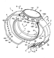
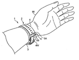
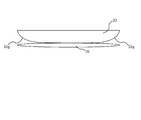
- FIG. 1 shows the appearance of a sphygmomanometer according to an embodiment of the present invention (the whole is denoted by reference numeral 1) as viewed obliquely with the belt 2 fastened.
- FIG. 2 shows the appearance of the sphygmomanometer 1 as viewed obliquely with the belt 2 opened.
- the sphygmomanometer 1 is broadly divided into a main body 10 and a body to be measured (in this example, a left hand as a site to be measured as shown in FIG. 13C to be described later).
- the dimension in the width direction X of the belt 2 is set to 29 mm in this example. Further, the thickness of the belt 2 is set to 2 mm in this example.
- the main body 10 includes a substantially short cylindrical case 10B, a circular glass 10A attached to the upper part of the case 10B (in FIGS. 1 and 2), and a back cover attached to the lower part of the case 10B. 10C (see FIG. 6).
- a pair of left and right (in FIGS. 1 and 2) protruding lugs 10B1, 10B2; 10B3, 10B4 for attaching the belt 2 are integrally provided on the side surface of the case 10B.
- a display 50 that forms a display screen is provided in the glass 10A at the top of the case 10B.
- a measurement switch 52A for instructing the start or stop of blood pressure measurement and a display screen of the display 50 are returned to a predetermined home screen.
- Home switch 52B, and a recording call switch 52C for instructing display unit 50 to display past measurement records such as blood pressure and activity (these switches are collectively referred to as operation unit 52).
- a blood pressure measuring element including a pump 30 is mounted inside the main body 10 (described in detail later).
- the sphygmomanometer 1 includes functions of an activity meter and a pulse meter. That is, the sphygmomanometer 1 is configured as a multifunctional device having a wristwatch-type wearable device.
- the main body 10 is small and thin so as not to disturb the daily activities of the user.
- the belt 2 includes a belt-shaped first belt portion 3 extending from the main body 10 to one side in one direction (right side in FIG. 2) and the other side in one direction (in FIG. 2, And a belt-like second belt portion 4 extending to the left side).
- the base portion 3e on the side closer to the main body 10 of the first belt portion 3 is connected to the lugs 10B1 and 10B2 of the main body 10 via a connecting rod 7 (known spring rod) extending in the belt width direction X. As shown by a double arrow A, it is rotatably attached.
- a base portion 4e on the side closer to the main body 10 in the second belt portion 4 is connected to a lug 10B3, 10B4 of the main body 10 in a belt width direction X (a connecting rod 8 (known spring bar)). As shown by a double arrow B, it is rotatably attached.
- a buckle 5 is attached to the distal end portion 3 f of the first belt portion 3 on the side far from the main body 10.
- the buckle 5 is of a known type, and includes a substantially U-shaped frame-like body 5A, a stick 5B, and a connecting rod 5C extending in the belt width direction X.
- the frame-like body 5A and the stick 5B are attached to the tip 3f of the first belt portion 3 on the side far from the main body 10 so as to be rotatable as indicated by a double arrow C via the connecting rod 5C. ing.
- a ring shape is provided at a predetermined position in the longitudinal direction of the first belt portion 3 (corresponding to the circumferential direction Y of the left wrist 90).
- the belt holding portions 6A and 6B are integrally provided.
- the inner peripheral surface 3a of the first belt portion 3 does not protrude toward the inner peripheral side at the belt holding portions 6A and 6B, and is formed substantially flat (curved as a whole, but locally). . Thereby, it is intended that the belt 2 uniformly surrounds and restrains the outer peripheral side of the cuff structure 20.
- a plurality of small holes 4w, 4w,... Penetrate in the thickness direction of the second belt portion 4 between the root portion 4e of the second belt portion 4 and the tip portion 4f far from the main body 10. Is formed.
- a portion connected to the front end portion 4f of the second belt portion 4 is passed through the frame-like body 5A of the buckle 5, and a plurality of second belt portions 4 are provided.
- the first belt portion 3 and the second belt portion 4 constituting the belt 2 are flexible in the thickness direction and substantially in the longitudinal direction (corresponding to the circumferential direction Y of the left wrist 90). It is made of a plastic material that exhibits non-stretchability. Accordingly, the belt 2 can easily surround and restrain the outer peripheral side of the cuff structure 20 when being worn, and can also assist the compression of the left wrist 90 during blood pressure measurement described later.
- the 1st belt part 3 and the 2nd belt part 4 may consist of leather materials.
- the frame 5A and the stick 5B constituting the buckle 5 are made of a metal material in this example, but may be made of a plastic material.
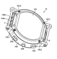
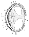
- the cuff structure 20 includes a curler 24 disposed on the outermost periphery, a press cuff 23 disposed along the inner peripheral surface of the curler 24, and an inner peripheral surface of the press cuff 23.
- a back plate 22 as a reinforcing plate arranged along the back plate 22 and a sensing cuff 21 arranged along the inner peripheral surface of the back plate 22 are included.
- the belt 2, the curler 24, and the pressing cuff 23 described above function as a pressing member that can generate a pressing force toward the wrist, and the back plate 22 is used as a measurement site by these pressing members.
- the wrist is pressed through a sensing cuff 21 inserted between the back plate 22 and the wrist.
- FIG. 3B shows a planar layout when the cuff structure 20 in FIG. 2 is in an unfolded state with the inner peripheral surface 20a being the foremost surface.
- FIG. 3A shows a cross section taken along line IIIA-IIIA in FIG.
- FIG. 4A shows an enlarged view of the vicinity of the tip of the cuff structure 20 in FIG.
- FIG. 4B shows a cross section taken along line IVB-IVB in FIG.
- FIG. 5A shows a planar layout of the press cuff 23.
- FIG. 5B shows a planar layout of the back plate 22 with the pressing cuff 23 as a background.
- the curler 24, the press cuff 23, the back plate 22, and the sensing cuff 21 each have a strip shape that is elongated in one direction (Y direction).
- the sensing cuff 21 includes a first sheet 21A that is in contact with the left wrist 90, and a second sheet 21B that faces the first sheet 21A.
- the peripheral portions 21m of the first and second sheets 21A and 21B are in close contact with each other by welding to form a bag shape.
- FIG. 4 (B) along the longitudinal direction Y of the sensing cuff 21 in a natural state, at a position connected to the edge portions 21m and 21m on both sides with respect to the width direction X of the sensing cuff 21.
- the slacks 21r and 21r are provided to extend. Further, as shown in FIG.
- a slack 21r extending along the width direction X of the sensing cuff 21 is provided at a location that continues to.
- a slack 21r can be formed by a known method, for example, when the peripheral portions 21m of the first and second sheets 21A and 21B are welded to each other. As can be seen from FIGS.
- the end of the sensing cuff 21 in the longitudinal direction Y has a pressure transmission fluid (in this example, to the sensing cuff 21).
- Air or a flexible tube 38 for discharging the pressure transmission fluid from the sensing cuff 21 is attached.
- An inner peripheral surface 20 a of the cuff structure 20 is configured by the first sheet 21 ⁇ / b> A of the sensing cuff 21.
- the pressing cuff 23 includes two fluid bags 23-1 and 23-2 stacked in the thickness direction, as can be seen from FIGS. 4 (A) and 4 (B).
- the dimension in the longitudinal direction Y of the inner circumferential fluid bag 23-1 is slightly smaller than the dimension (L2) in the longitudinal direction Y of the outer circumferential fluid bag 23-2. Is set.
- a pressure transmission fluid (air in this example) is supplied to the pressure cuff 23 at the end on the base side (+ Y side) with respect to the longitudinal direction Y of the fluid bag 23-2 on the outer peripheral side, or the pressure cuff A flexible tube 39 for discharging a fluid for pressure transmission from 23 is attached. Further, a plurality of (four in this example) through holes 23o, 23o,... Are formed between the inner peripheral fluid bag 23-1 and the adjacent outer peripheral fluid bag 23-2. Yes. Thereby, a fluid for pressurization (air in this example) can be circulated between the two fluid bags 23-1, 23-2 through the through holes 23o, 23o,.
- the back plate 22 is made of a plate-like resin (in this example, polypropylene) having a thickness of about 1 mm in this example. As can be seen from FIGS. 3A and 3B, the back plate 22 is disposed along the surface opposite to the measurement site with respect to the sensing cuff 21. Further, the back plate 22 extends in a band shape beyond the length of the sensing cuff 21 in the longitudinal direction Y (corresponding to the circumferential direction of the left wrist 90). Therefore, the back plate 22 works as a reinforcing plate and can transmit the pressing force from the pressing cuff 23 to the entire area in the longitudinal direction Y of the sensing cuff 21 (corresponding to the circumferential direction of the left wrist 90).
- a plate-like resin in this example, polypropylene
- the inner surface 22a and the outer surface 22b of the back plate 22 have grooves 22d1, which are V-shaped or U-shaped in cross section extending in the width direction X.
- a plurality of 22d2 are provided in parallel with each other in the longitudinal direction Y so as to be separated from each other.
- the grooves 22d1 and 22d2 are provided at the same position corresponding to each other between the inner peripheral surface 22a and the outer peripheral surface 22b of the back plate 22.
- the back plate 22 is thinner at the locations of the grooves 22d1 and 22d2 than at other locations, and is easily bent. Accordingly, when the user puts the left wrist 90 and the cuff structure 20 together with the belt 2 when wearing (step S22 in FIG. 12 described later), the cuff structure 20 is placed on the left wrist.
- the back plate 22 does not prevent the end plate 90 from bending along the circumferential direction Y.
- the curler 24 is made of a resin plate having a certain degree of flexibility and hardness (in this example, polypropylene) having a thickness of about 1 mm in this example.
- the curler 24 extends in a band shape beyond the length of the pressing cuff 23 in the longitudinal direction Y (corresponding to the circumferential direction of the left wrist 90) in the deployed state. Exist.
- the curler 24 has a curved shape along the circumferential direction Y surrounding the left wrist 90 in a natural state. Thereby, the shape of the cuff structure 20 in the natural state is maintained in a curved state along the circumferential direction Y of the left wrist 90 as shown in FIG.
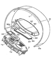
- a back cover 10 ⁇ / b> C is provided on the back side of the main body 10.
- the back cover 10C has four through holes 10C1, 10C2, 10C3, and 10C4, and is fixed to the back side of the case 10B with screws (not shown) through these through holes 10C1, 10C2, 10C3, and 10C4.
- a portion of the side surface of the case 10B concealed by the base portion 3e of the first belt portion 3 is provided with filter-equipped intake / exhaust holes 10Bo, 10Bo,... (The same applies to the portion concealed by the base portion 4e of the second belt portion 4). ).
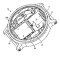
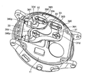
- FIG. 7 shows the back side of the main body 10 with the above-described curler 24 in an exploded state with the back cover 10C removed.
- An inner case member 11 for mounting a blood pressure measurement element is housed in the case 10B of the main body 10.
- An annular groove 11d is formed on the back side of the inner case member 11 so as to surround the protrusion 11p.
- a ring 24o having a shape corresponding to the annular groove 11d is formed in the root portion 24f of the curler 24.
- one end 20 f of the cuff structure 20 (the root portion 24 f of the curler 24) is attached to the main body 10.
- the other end 20e of the cuff structure 20 (the tip 24e of the curler 24) is a free end.
- the cuff structure 20 faces the inner peripheral surfaces 3a and 4a of the belt 2 and can be separated from the inner peripheral surfaces 3a and 4a.
- the cuff structure 20 When the cuff structure 20 is attached to the main body 10 in this way, the one end 20f of the cuff structure 20 is securely held by the main body 10.
- the cuff structure 20 can be exchanged for the main body 10 regardless of the belt 2 by opening the back cover 10 ⁇ / b> C of the main body 10.
- the dimension in the longitudinal direction Y (corresponding to the circumferential direction of the left wrist 90) of the cuff structure 20 can be set to an optimum dimension regardless of the belt 2.
- the main body 10 and the belt 2 are formed separately from each other, and the belt 2 is attached to the main body 10. Therefore, during maintenance service, regardless of the cuff structure 20, The belt 2 can be exchanged with respect to the main body 10.
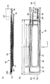
- the first flow path forming member 390 shown in FIG. 7 includes two sheet plates 391 and 392 that are opposed to each other and spread in a thin plate shape, and a predetermined distance between these sheet plates 391 and 392 (this example Then, the spacer portion 393 is maintained at 0.7 mm.
- the second flow path forming member 380 includes two sheet plates 381 and 382 that spread in a thin plate shape facing each other, and a spacer portion 383 that keeps these sheet plates 381 and 382 at a predetermined interval. It is made up of. Note that the sheet plate 381 and the spacer portion 383 are shown in FIG. 9 (in FIG. 9, the illustration of the sheet plates 392 and 382 on the side far from the inner case member 11 is omitted for easy understanding).
- Lateral pins 390p and 380p are integrally attached to the end of the first flow path forming member 390 and the end of the second flow path forming member 380 so as to allow fluid flow, respectively.
- the flexible tube 39 from the pressing cuff 23 is connected to the first flow path forming member 390 via the lateral pin 390p.
- the flexible tube 38 from the sensing cuff 21 is connected to the second flow path forming member 380 via the lateral pin 380p.
- the first flow path forming member 390 and the second flow path forming member 380 are formed by integral molding of elastomer.
- the thickness dimension of the first flow path forming member 390 and the second flow path forming member 380 is set to 1.2 mm.
- FIG. 10 shows a block configuration of a control system of the sphygmomanometer 1.
- the main body 10 of the sphygmomanometer 1 includes a main CPU (Central Processing Unit) 100 as a control unit and a sub CPU 101 as blood pressure measurement elements for executing blood pressure measurement in addition to the display 50 and the operation unit 52 described above.
- a memory 51 as a storage unit, an acceleration sensor 54, a communication unit 59, a battery 53, a first pressure sensor 31 for detecting the pressure of the pressing cuff 23, and a second pressure sensor 32 for detecting the pressure of the sensing cuff 21.
- a pump 30, an on-off valve 33, and a pump drive circuit 35 for driving the pump 30 are mounted.
- the main CPU 100 mainly controls the entire operation of the sphygmomanometer 1, and the sub CPU 101 mainly controls the operation of the air system.
- the main CPU 100 and the sub CPU 101 are simply referred to as a CPU 100.
- the display 50 is an LCD (Liquid Cristal Display), and displays information related to blood pressure measurement such as a blood pressure measurement result and other information according to a control signal from the CPU 100.
- the display device 50 is not limited to an organic EL display, and may include another type of display device 50 such as an organic EL (Electro-Luminescence) display.
- the display device 50 may include an LED (Light (Emitting Diode).
- the operation unit 52 includes a measurement switch 52A for instructing start or stop of blood pressure measurement, a home switch 52B for returning the display screen of the display 50 to a predetermined home screen, A recording call switch 52C for instructing the display 50 to display measurement records such as blood pressure and activity amount.
- these switches 52A to 52C are push-type switches, and input an operation signal in accordance with an instruction to start or stop blood pressure measurement by the user to the CPU 100.
- the operation unit 52 is not limited to a push-type switch, and may be, for example, a pressure-sensitive (resistance) or proximity (capacitance) touch panel switch.
- a microphone (not shown) may be provided, and a blood pressure measurement start instruction may be input by a user's voice.
- the memory 51 includes data of a program for controlling the sphygmomanometer 1, data used for controlling the sphygmomanometer 1, setting data for setting various functions of the sphygmomanometer 1, data of measurement results of the blood pressure value, etc. Is stored temporarily.
- the memory 51 is used as a work memory when the program is executed.
- the CPU100 performs various functions as a control part according to the program for controlling the blood pressure meter 1 memorize
- FIG. For example, when executing the blood pressure measurement function, the CPU 100, based on signals from the first pressure sensor 31 and the second pressure sensor 32, in response to an instruction to start blood pressure measurement from the measurement switch 52A of the operation unit 52, Control for driving the pump 30 and the on-off valve 33 is performed. Further, the CPU 100 performs control to calculate a blood pressure value, a pulse, and the like based on a signal from the second pressure sensor 32.
- the acceleration sensor 54 is composed of a three-axis acceleration sensor integrated in the main body 10.
- the acceleration sensor 54 outputs to the CPU 100 an acceleration signal representing the acceleration of the main body 10 in three directions orthogonal to each other.
- the output of the acceleration sensor 54 is used to measure the amount of activity.
- the communication unit 59 is controlled by the CPU 100 to transmit predetermined information to an external device via a network, or receives information from an external device via the network and passes it to the CPU 100. Communication via this network may be either wireless or wired.
- the network is the Internet, but is not limited to this, and may be another type of network such as an in-hospital LAN (Local Area Network), or a pair using a USB cable or the like. 1 communication may be sufficient.
- the communication unit 59 may include a micro USB connector.
- the battery 53 is a rechargeable secondary battery.
- the battery 53 is an element mounted on the main body 10, in this example, the CPU 100, the memory 51, the acceleration sensor 54, the communication unit 59, the first pressure sensor 31, the second pressure sensor 32, the pump 30, the on-off valve 33, and Electric power is supplied to each element of the pump drive circuit 35.
- the pump 30 is a piezoelectric pump in this example, and is driven by a pump driving circuit 35 based on a control signal given from the CPU 100.
- the pump 30 is connected to the pressing cuff 23 through the first flow path forming member 390 and the flexible tube 39 constituting the first flow path so that fluid can flow.
- the pump 30 can supply air as a pressurizing fluid to the pressing cuff 23 through the first flow path forming member 390 and the flexible tube 39.
- the pump 30 is equipped with an exhaust valve (not shown) that is controlled to open and close as the pump 30 is turned on / off.
- the exhaust valve closes when the pump 30 is turned on and helps to enclose air in the pressure cuff 23, while it opens when the pump 30 is turned off to allow the air in the pressure cuff 23 to be flexible.
- the gas is discharged into the atmosphere through the tube 39 and the first flow path forming member 390.
- the exhaust valve has a check valve function, and the exhausted air does not flow backward.
- the pump 30 is connected to the sensing cuff 21 through the second flow path forming member 380 constituting the second flow path and the flexible tube 38 so that fluid can flow.
- An open / close valve (in this example, a normally open electromagnetic valve) 33 is interposed in the second flow path (actually, between the first flow path forming member 390 and the second flow path forming member 380). It is inserted.
- the on-off valve 33 is controlled to open and close (opening) based on a control signal given from the CPU 100. When the on-off valve 33 is in an open state, air can be supplied from the pump 30 to the sensing cuff 21 through the second flow path as a pressure transmitting fluid and stored.
- the first pressure sensor 31 and the second pressure sensor 32 are each composed of a piezoresistive pressure sensor in this example.
- the first pressure sensor 31 detects the pressure in the pressing cuff 23 via the first flow path forming member 390 and the flexible tube 39 that constitute the first flow path.
- the second pressure sensor 32 detects the pressure in the sensing cuff 21 via the second flow path forming member 380 and the flexible tube 38 constituting the second flow path.
- the pump 30 and the first pressure sensor 31 are arranged at the approximate center of the inner case member 11 within the main body 10.
- the on-off valve 33 and the second pressure sensor 32 are arranged around the inner case member 11.
- the first flow path forming member 390 is disposed on the back side of the inner case member 11 and the discharge port 30d of the pump 30 and the first pressure sensor.
- the air inlet 31d of 31 and the inlet 33i of the on-off valve 33 are arranged.
- the second flow path forming member 380 is disposed on the back side of the inner case member 11 so as to straddle the outlet 33 e of the on-off valve 33 and the air inlet 32 d of the second pressure sensor 32.
- the sphygmomanometer 1 is configured in a small and integrated manner by mounting the blood pressure measuring element as described above on the main body 10. Therefore, user convenience is good.
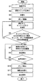
- FIG. 11 shows an operation flow when the user performs blood pressure measurement by executing the blood pressure measurement method of the embodiment with the sphygmomanometer 1.
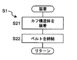
- the user wears the sphygmomanometer 1 on the left wrist 90 as a measurement site.
- the user wears the cuff structure 20 on the left wrist 90 using the right hand 99 (step S21 in FIG. 12).
- the cuff structure 20 is curved along the circumferential direction Y of the left wrist 90 by the curler 24 in a natural state. Therefore, in this example, the user fits the cuff structure 20 on the outer peripheral surface of the left wrist 90 using the right half body hand (in this example, the right hand 99) opposite to the left half body to which the left wrist 90 belongs.
- the cuff structure 20 can be easily attached to the left wrist 90.
- the cuff structure 20 In a state where the cuff structure 20 is attached to the left wrist 90, even if the user releases the right hand 99 from the cuff structure 20, the cuff structure 20 grips the left wrist 90.
- the body 20 (and the belt 2, the main body 10) is difficult to drop off.
- the user uses the right hand 99 to bring the belt 2 around the left wrist 90 and the cuff structure 20 together.
- a portion connected to the front end portion 4f of the second belt portion 4 is passed through the frame-like body 5A of the buckle 5 of the first belt portion 3, and a plurality of small holes 4w, 4w,.
- a stick 5B with a buckle 5 is inserted into any one of the above.
- the 1st belt part 3 and the 2nd belt part 4 are fastened (step S22 in FIG. 12).
- the belt 2 extending from the main body 10 surrounds the left wrist 90, and the band-shaped cuff structure 20 having one end 20 f attached to the main body 10 is arranged closer to the left wrist 90 than the belt 2. It becomes a state.
- the cuff structure 20 can be separated from the inner peripheral surfaces 3a and 4a of the belt 2, and the other end 20e on the side opposite to the one end 20f of the cuff structure 20 is a free end. ing. Accordingly, when the first belt portion 3 and the second belt portion 4 are fastened, the cuff structure 20 receives an inward force from the belt 2 and just follows the outer peripheral surface of the left wrist 90. 20 can slide or deform. Thereby, in the wearing state, the cuff structure 20 and the belt 2 are in close contact with the outer peripheral surface of the left wrist 90 in this order, that is, the left wrist 90 is surrounded as a whole in a band shape. In this manner, the sphygmomanometer 1 can be easily attached to the left wrist 90.
- the bag-shaped pressing cuff 23 extends along the circumferential direction Y of the left wrist 90 on the inner peripheral side of the curler 24 included in the cuff structure 20.
- the bag-like sensing cuff 21 included in the cuff structure 20 is arranged on the inner peripheral side of the pressing cuff 23 so as to contact the left wrist 90 and cross the artery passing portion 90a of the left wrist 90. It extends in the circumferential direction Y.
- a back plate 22 included in the cuff structure 20 is inserted between the pressing cuff 23 and the sensing cuff 21 and extends along the circumferential direction Y of the left wrist 90.
- the main body 10 and the belt 2 are not shown.
- the radius 93, ulna 94, radial artery 91, ulnar artery 92, and tendon 96 of the left wrist 90 are shown.
- step S2 in FIG. 11 when the user presses the measurement switch 52A of the operation unit 52 provided in the main body 10 (step S2 in FIG. 11), the CPU 100 initializes the processing memory area (step S3 in FIG. 11). In addition, the CPU 100 turns off the pump 30 via the pump drive circuit 35, opens the exhaust valve built in the pump 30, and maintains the on-off valve 33 in the open state so that the inside of the pressing cuff 23 and the sensing cuff 21 Exhaust the air. Subsequently, the control for adjusting 0 mmHg of the first pressure sensor 31 and the second pressure sensor 32 is performed.
- the CPU 100 operates as a pressurization control unit and a fluid accommodation control unit, turns on the pump 30 via the pump drive circuit 35 (step S4 in FIG. 11), maintains the open / close valve 33 in the open state, and presses the pump 30 Pressurization of the cuff 23 and the sensing cuff 21 is started (step S5 in FIG. 11).
- the pump 30 is driven via the pump drive circuit 35 while monitoring the pressure of the pressure cuff 23 and the sensing cuff 21 by the first pressure sensor 31 and the second pressure sensor 32, respectively.
- the first flow path (the first flow path forming member 390 and the flexible tube 39) is passed through the pressing cuff 23, and the second flow path (the second flow path forming member 380 and the flexible tube 39 is flexible). Control is performed to send air to the sensing cuff 21 through the tube 38).
- step S6 in FIG. 11 the CPU 100 operates as a fluid accommodation control unit, and the pressure of the sensing cuff 21 has reached a predetermined pressure (15 mmHg in this example) or the driving time of the pump 30 is predetermined. It is determined whether or not only the time (3 seconds in this example) has elapsed. The reason for making this determination is to confirm whether or not an appropriate amount of air is contained in the sensing cuff 21. If NO in step S6 of FIG. 11, the process waits until the pressure of the sensing cuff 21 reaches a predetermined pressure or until the driving time of the pump 30 has elapsed for a predetermined time. The amount of the “appropriate amount” of the pressure transmitting fluid stored in the sensing cuff 21 will be described later.
- step S6 in FIG. 11 If “YES” in the step S6 in FIG. 11, it is determined that an appropriate amount of air is accommodated in the sensing cuff 21. Then, in step S7 in FIG. 11, the CPU 100 operates as a pressurization control unit, keeps the on-off valve 33 in a closed state, and continues control for supplying air from the pump 30 to the pressing cuff 23 through the first flow path. As a result, the pressure cuff 23 is expanded and the pressure is gradually increased to press the left wrist 90. At this time, the back plate 22 transmits the pressing force from the pressing cuff 23 to the sensing cuff 21. The sensing cuff 21 presses the left wrist 90 (including the artery passage portion 90a).
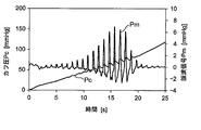
- the CPU 100 monitors the pressure Pc of the sensing cuff 21, that is, the pressure of the arterial passage portion 90a of the left wrist 90 with the second pressure sensor 32 in order to calculate the blood pressure value.
- the pulse wave signal Pm is acquired.
- FIG. 16 illustrates the waveforms of the pressure Pc and pulse wave signal Pm of the sensing cuff 21 obtained in this pressurization process.
- FIG. 15A and 15B show the longitudinal direction of the left wrist 90 (corresponding to the width direction X of the cuff) in a pressurized state in which an appropriate amount of air is accommodated in the sensing cuff 21 and the on-off valve 33 is closed.
- the cross section along is shown typically.
- FIG. 15A shows a cross section (corresponding to a cross section taken along line XVA-XVA in FIG. 14) of a portion through which the tendon 96 of the left wrist 90 passes.
- FIG. 15B shows a cross section (corresponding to a cross section taken along line XVB-XVB in FIG. 14) of the portion of the left wrist 90 through which the radial artery 91 passes.
- FIG. 15A shows a cross section (corresponding to a cross section taken along line XVA-XVA in FIG. 14) of a portion through which the tendon 96 of the left wrist 90 passes.
- FIG. 15B shows a cross section (corresponding to a cross section taken along line XVB-XVB
- the portion through which the radial artery 91 of the left wrist 90 passes is relatively soft, so that there is a gap 21w where air exists between the first sheet 21A and the second sheet 21B of the sensing cuff 21. Remaining. Therefore, the portion of the sensing cuff 21 that faces the radial artery 91 can reflect the pressure of the artery passing portion 90 a of the left wrist 90.
- the portion through which the tendon 96 of the left wrist 90 passes is relatively hard. Therefore, in the portion corresponding to the approximate center in the width direction X of the sensing cuff 21, the first sheet 21 ⁇ / b> A and the second sheet The sheet 21B is in contact with each other.
- the slack 21r extending along the longitudinal direction Y (corresponding to the circumferential direction of the left wrist 90) as described above. Since 21r is provided, gaps 21w ′ and 21w ′ in which air exists along the longitudinal direction Y remain. As a result, the air stored in the sensing cuff 21 can flow along the longitudinal direction Y of the sensing cuff 21 through the gaps 21w ′ and 21w ′. Accordingly, the sensing cuff 21 can successfully transmit the pressure applied to the artery passage portion 90a of the left wrist 90 to the second pressure sensor 32 in the main body 10 as the pressure of air (pressure transmission fluid). .
- step S8 of FIG. 11 the CPU 100 operates as a blood pressure calculation unit, and applies a known algorithm by an oscillometric method based on the pulse wave signal Pm acquired at this time point to determine the blood pressure value (systolic period). Attempts to calculate blood pressure SBP and diastolic blood pressure DBP).
- the cuff pressure has reached the upper limit pressure (for example, 300 mmHg is determined in advance for safety). Unless otherwise specified, the processes in steps S7 to S9 are repeated.
- step S9 the CPU 100 stops the pump 30 (step S10), opens the on-off valve 33 (step S11), and within the press cuff 23, the sensing cuff 21. Control to exhaust the air inside. Finally, the measurement result of the blood pressure value is displayed on the display device 50 (step S12).
- the blood pressure calculation may be performed not in the pressurizing process of the pressing cuff 23 but in the depressurizing process.
- the second pressure sensor 32 is separated from the pressure cuff 23 by the pressure Pc of the sensing cuff 21, that is, the left wrist 90
- the pressure of the arterial passage portion 90a is detected. Therefore, as a result of setting the dimension in the width direction X of the belt 2 and the cuff structure 20 (simply referred to as “cuff” where appropriate) to a small size (for example, about 25 mm), the pressure cuff 23 is moved in the thickness direction during pressurization. Even in the case where compression loss occurs due to large expansion, blood pressure can be measured with high accuracy.
- the sensing cuff 21 extends in the circumferential direction Y so as to cross the arterial passage portion 90 a of the left wrist 90. Accordingly, when the user actually wears the sphygmomanometer 1 on the left wrist 90, even if the cuff is displaced to some extent with the main body 10 in the circumferential direction Y of the left wrist 90, the arteries passing portion 90a of the left wrist 90 The sensing cuff 21 does not come off. Therefore, it is possible to prevent the blood pressure measurement value from varying from the actual blood pressure, and as a result, the blood pressure can be measured with high accuracy.
- the sensing cuff 21 may contain a fluid for pressure transmission and may be sealed.
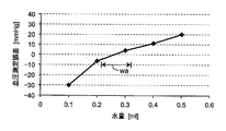
- FIG. 17 shows blood pressure measurement error (average value) when water is used as the pressure transmission fluid stored in the sensing cuff 21 and the amount of water stored in the sensing cuff 21 is variably set.
- the blood pressure measurement error is a blood pressure value measured by a standard (accurate) sphygmomanometer from a blood pressure value (systolic blood pressure SBP) measured by the sphygmomanometer 1 for a certain user (subject). It means the difference obtained by subtracting the systolic blood pressure SBP) (this is referred to as “reference blood pressure value”).
- (Blood pressure measurement error) (blood pressure value measured by sphygmomanometer 1) ⁇ (reference blood pressure value) It is. As can be seen from FIG. 17, if the amount of water stored in the sensing cuff 21 is in the range wa of 0.26 ml ⁇ 0.05 ml, the blood pressure measurement error is within ⁇ 5 mmHg, which is considered to be an appropriate amount.
- the range wa of 0.26 ml ⁇ 0.05 ml is an appropriate amount for the fluid for pressure transmission accommodated in the sensing cuff 21.
- the pressure of the sensing cuff 21 has reached a predetermined pressure (15 mmHg in this example), or the driving time of the pump 30 is a predetermined time (3 seconds in this example).
- the criterion for determining whether or not only the time has passed is set so as to satisfy the condition that the amount of air as the pressure transmission fluid accommodated in the sensing cuff 21 is in the range wa of 0.26 ml ⁇ 0.05 ml. Yes.
- the appropriate amount of the pressure transmitting fluid accommodated in the sensing cuff 21 depends on the size of the sensing cuff 21 and the like.
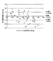
- the scatter diagram of FIG. 18 shows the fluid for pressure transmission accommodated in the sensing cuff 21 for a plurality of users (in this example, each of five subjects whose systolic blood pressure SBP is measured from 97 mmHg to 149 mmHg).
- the blood pressure measurement error is increased on the plus side for a plurality of users, as indicated by a cross in the figure. If the amount of water is small, the blood pressure measurement error is larger on the minus side for a plurality of users, as indicated by ⁇ in the figure.
- the sphygmomanometer 1 when a plurality of users actually mount the sphygmomanometer 1 on the left wrist 90 and perform blood pressure measurement, the areas of the soft portions where the two arteries, the radial artery 91 and the ulnar artery 92, are different depending on the user. .
- the amount of water is an appropriate amount, blood pressure measurement errors are suppressed for a plurality of users. Therefore, it can be said that the sphygmomanometer 1 has confirmed that blood pressure can be accurately measured even when the areas of the soft portions where the two arteries, the radial artery 91 and the ulnar artery 92 are present, are different.
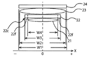
- FIG. 19 is a schematic diagram showing the relationship of dimensions in the width direction X of the curler 24, the pressing cuff 23, the back plate 22, and the sensing cuff 21.
- the center positions of the curler 24, the press cuff 23, the back plate 22, and the sensing cuff 21 in the width direction X are set to the origin of the X coordinate.
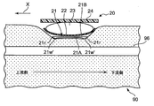
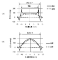
- FIG. 20A is a diagram showing a simulation result of the pressure distribution on the skin surface (left wrist 90) and the pressure distribution around the blood vessel when a pressure of 300 mmHg is applied to the back plate 22 by the pressure cuff.
- FIG. 20A is a diagram showing a simulation result of the pressure distribution on the skin surface (left wrist 90) and the pressure distribution around the blood vessel when a pressure of 300 mmHg is applied to the back plate 22 by the pressure cuff.
- FIGS. 20A and 20B are diagram showing a simulation result of the pressure distribution on the skin surface and the pressure distribution around the blood vessel when a pressure of 300 mmHg is applied to the skin surface (left wrist 90) by the pressure cuff.
- the X coordinate position in FIGS. 20A and 20B corresponds to the X coordinate position in FIG.
- the back plate 22 used in the simulation is a plate-like member and has a shape having an edge 22c at the edge 22f in the width direction X, and stress concentration due to the edge 22c occurs. This is probably because As described above, when the pressure is pressed through the back plate 22, the uniform pressure range is wider than that of the pressure cuff 23 alone, but the pressure between the skin surface position and the blood vessel position is shifted due to the stress concentration. . Therefore, when the dimension in the width direction X of the sensing cuff 21 is the same as the dimension in the width direction X of the back plate 22, the pressure in the width direction X with respect to the measurement site of the sensing cuff 21 depends on the skin surface position and the blood vessel. Deviation occurs in position, and an error occurs in the measured blood pressure value.
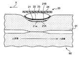
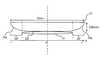
- FIG. 21 is a schematic diagram showing a back plate 22 in which a surface 22g facing the measurement site of the edge 22f on both sides in the width direction X is curved in a direction away from the measurement site toward the tip.
- FIG. 22 is a schematic diagram showing a back plate 22 in which a surface 22g facing the measurement site of the edge 22f on both sides in the width direction X is curved in a direction away from the measurement site. 21 and 22, the center positions of the back plate 22 and the sensing cuff 21 in the width direction X are set to the origin of the X coordinate.
- FIG. 21 is a schematic diagram showing a back plate 22 in which a surface 22g facing the measurement site of the edge 22f on both sides in the width direction X is curved in a direction away from the measurement site.
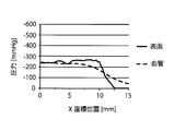
- FIG. 23 is a diagram showing simulation results of the pressure distribution on the skin surface and the pressure distribution around the blood vessel when a pressure of 300 mmHg is applied to the back plate 22 of FIG.
- FIG. 24 is a diagram showing simulation results of the pressure distribution on the skin surface and the pressure distribution around the blood vessel when a pressure of 300 mmHg is applied to the back plate 22 of FIG.
- the pressure at the skin surface position of the measurement site is higher than the pressing force at the blood vessel position in the vicinity of the edge 22c.
- the edge 22c is formed, so that stress concentration due to the edge 22c occurs. .
- the width direction X of the sensing cuff 21 as described above.
- the size of the back plate 22 in the width direction X is made larger than the size of the back plate 22, and the surface 22 g of the back plate 22 facing the portion to be measured of the edge 22 f on both sides in the width direction X is moved toward the tip. It has been found that it is preferable to curve in a direction away from the measurement site.
- the pressure difference between the sensing cuff 21 and the measurement site is eliminated at the skin surface position and the blood vessel position of the measurement site, the pressure becomes more uniform, and the error in the measured blood pressure value is reduced.
- blood pressure can be measured with high accuracy.
- the surface 22g may be curved by processing the surface 22g into a round shape or processing it into a taper shape. That is, the influence of stress concentration due to the edge can be reduced by making the edge portions 22f on both sides of the back plate 22 gradually thinner toward the tip.
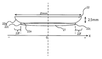
- FIG. 25 shows the width direction dimension of the back plate 22 in which the surface 22g facing the measurement site of the edge 22f on both sides in the width direction X is curved in a direction away from the measurement site toward the tip. It is a schematic diagram at the time of making it the same as the width direction dimension of the cuff 21.
- the skin surface position of the site to be measured is compared with the case where the dimension in the width direction X of the back plate 22 is larger than the dimension in the width direction X of the sensing cuff 21 as shown in FIG.
- the pressure difference with respect to the measurement site of the sensing cuff 21 occurs, and the pressure uniformity is impaired.
- the width of the back plate 22 Even if the direction dimension is the same as the width direction dimension of the sensing cuff 21, the blood pressure can be measured with high accuracy.
- grooves 22d1 and 22d2 having a V-shaped or U-shaped cross section extending in the width direction X are spaced apart from each other in the longitudinal direction Y on the inner peripheral surface 22a and the outer peripheral surface 22b of the back plate 22. It was assumed that a plurality were provided in parallel. However, the present invention is not limited to this.
- the back plate is composed of a set of a plurality of small pieces separated from each other with respect to the longitudinal direction Y so that the back plate can be curved along the circumferential direction (longitudinal direction Y) of the part to be measured. May be arranged over a range exceeding the length of the sensing cuff 21 in the circumferential direction (longitudinal direction Y) of the measurement site. Also in this case, substantially the same effect as in the above-described back plate 22 can be obtained.
- the measurement site to which the sphygmomanometer is attached is the left wrist 90.
- the sphygmomanometer of the present invention may be configured to be optically symmetric with respect to the sphygmomanometer 1 shown in FIGS. 1 and 2 and attached to the right wrist.
- the part to be measured may be a part other than the wrist such as the upper arm or the lower limb.
- the main body 10 and the belt 2 are formed separately from each other, and the belt 2 is attached to the main body 10.
- the present invention is not limited to this.
- the main body 10 and the belt 2 may be integrally formed.
- the first belt portion 3 and the second belt portion 4 of the belt 2 are fastened or released by the buckle 5.
- the present invention is not limited to this.
- the first belt portion 3 and the second belt portion 4 may be connected to each other via a three-fold buckle that can be opened and closed.
- the present invention is not limited to this example, and the curler 24 may be omitted.
- the belt 2 is formed by a single band-shaped body
- the pressing cuff 23 is disposed along the inner circumferential surface of the band-shaped body
- the back plate 22 is disposed along the inner circumferential surface of the pressing cuff 23.
- the sensing cuff 21 may be disposed along the inner peripheral surface of the back plate 22.
- the belt 2 and the pressing cuff 23 described above function as a pressing member capable of generating a pressing force toward the wrist, and the back plate 22 is moved toward the wrist as a measurement site by these pressing members.
- the back cover 10 ⁇ / b> C of the main body 10 may be provided with a three-fold buckle that can be opened and closed, and the end of the belt 2 may be connected to the three-fold buckle.
- the pump 30 is driven until the pressure of the sensing cuff 21 reaches 15 mmHg, or the driving time of the pump 30 is set to 3 Seconds.
- the present invention is not limited to this example.
- the pump 30 is driven until the pressure of the sensing cuff 21 reaches, for example, 5 mmHg, and the sensing cuff 21 is filled with fluid.
- the amount of fluid in 21 may be optimized.
- the pump 30 is filled with air until the pressure reaches a high pressure, for example, 30 mmHg, and then the pump 30 is stopped and the exhaust valve is opened to reduce the pressure of the sensing cuff 21 to a low pressure, for example,
- the pressure in the sensing cuff 21 may be optimized by reducing the pressure to 15 mmHg and then closing the exhaust valve.
- an exhaust valve may be provided separately from the pump 30, and a valve drive circuit for driving the exhaust valve may be provided so as to be controllable by the CPU 100.
- the sensing cuff 21 has been described as an example in which the sensing cuff 21 is in direct contact with the left wrist 90 as the measurement site, but the present invention is not limited to this.
- the sensing cuff 21 may contact the left wrist 90 indirectly via another member (for example, a cover member).
- the belt 2, the curler 24, and the pressing cuff 23 are given as examples of the pressing member.
- the present invention is not limited to this example, and the pressing member that extends mechanically in the thickness direction may be used. Good.
- the present invention is not limited to this example, and includes a cuff including the belt 2 and the cuff structure 20 and a main body placed on a table.
- the main body may be provided with a pump.
- the cuff and the main body may be connected via an elongated tube, and fluid may be supplied from the main body to the cuff.
- the CPU 100 mounted on the sphygmomanometer 1 functions as a fluid accommodation control unit, a pressurization control unit, and a blood pressure calculation unit to perform blood pressure measurement (operation flow in FIG. 11).
- the present invention is not limited to this.
- a substantial computer device such as a smartphone provided outside the sphygmomanometer 1 works as a fluid accommodation control unit, a pressurization control unit, and a blood pressure calculation unit, and is connected to the sphygmomanometer 1 via the network 900. You may make it perform blood-pressure measurement (operation
Abstract
Description
被測定部位を取り巻いて装着されるべき袋状のセンシングカフと、
上記センシングカフに対して、上記被測定部位とは反対側の面に沿って配置された背板と、
上記背板を上記被測定部位へ向けて押圧するための押圧部材と、
上記センシングカフに収容された流体の圧力に基づいて血圧を算出する血圧算出部と、
を備え、
上記センシングカフが取り巻くべき上記被測定部位の周方向に対して垂直な長手方向に関して、上記背板の上記長手方向に沿った幅方向における両側の縁部の上記被測定部位に対向する面は、先端に向かうに連れて上記被測定部位から遠ざかる向きに湾曲している、
ことを特徴とする。
上記センシングカフの上記幅方向の寸法よりも、上記背板の上記幅方向の寸法が大きいことを特徴とする。
上記両側の縁部は、それぞれ先端に向かうに連れて次第に薄厚になっていることを特徴とする。
上記背板は、上記周方向に関して上記センシングカフの長さを越えて帯状に延在し、
上記背板は、上記周方向に沿って湾曲し得るように、この背板の幅方向に延びる断面V字状またはU字状の溝を、この背板の長手方向に関して互いに離間して複数平行に有することを特徴とする。
上記背板は、この背板が全体として上記周方向に沿って湾曲し得るように、上記周方向に関して互いに分離した複数の小片の集合からなり、
上記複数の小片の集合が、上記周方向に関して上記センシングカフの長さを越える範囲にわたって配置されていることを特徴とする。
上記センシングカフは、圧力伝達用の流体を収容可能に袋状に構成され、上記被測定部位の動脈通過部分を横切るように上記周方向に延在し、
上記押圧部材は、
上記被測定部位を上記周方向に取り巻いて装着されるべきベルトと、
上記ベルトの内周面に対向して配置され、加圧用の流体の供給を受けて上記被測定部位を圧迫するために、上記周方向に沿って延在する袋状の押圧カフとを含むことを特徴する。
ポンプを搭載した本体を備え、
上記ベルトは、上記本体から延在している、ことを特徴とする。
上記押圧カフ、上記背板、および上記センシングカフは、帯状で、上記本体に一端が取り付けられたカフ構造体を構成し、
このカフ構造体は、さらに、上記押圧カフの外周面に沿って、このカフ構造体の自然状態での形状を、上記周方向に沿って湾曲した状態に保つためのカーラを備えたことを特徴とする。
上記押圧部材によって上記センシングカフを介して上記被測定部位を圧迫する制御を行う加圧制御部と、
上記押圧部材および上記センシングカフが上記被測定部位に装着された装着状態で、上記センシングカフに上記圧力伝達用の流体を供給して収容させる制御を行う流体収容制御部と、を備え、
上記本体は、
上記ポンプと上記押圧カフとを流体流通可能に接続する第1の流路と、
上記ポンプまたは第1の流路と上記センシングカフとを流体流通可能に接続し、かつ、開閉弁が介挿された第2の流路と
を搭載し、
上記流体収容制御部は、上記装着状態で、上記開閉弁を開状態にして、上記ポンプまたは第1の流路から上記第2の流路を通して上記センシングカフに上記圧力伝達用の流体を供給して収容させ、
上記加圧制御部は、上記センシングカフに上記圧力伝達用の流体が収容された後、上記開閉弁を閉状態にして、上記ポンプから上記第1の流路を通して上記押圧カフに上記加圧用の流体を供給して上記被測定部位を圧迫することを特徴とする。
上記本体は、上記加圧制御部と、上記流体収容制御部と、上記血圧算出部と、を搭載していることを特徴とする。
被測定部位を取り巻いて装着されるべき袋状のセンシングカフと、
上記センシングカフに対して、前記被測定部位とは反対側の面に沿って配置され、上記センシングカフが取り巻くべき上記被測定部位の周方向に対して垂直な長手方向に関して、上記長手方向に沿った幅方向における両側の縁部の上記被測定部位に対向する面は、先端に向かうに連れて上記被測定部位から遠ざかる向きに湾曲している背板と、
上記背板を上記被測定部位へ向けて押圧するための押圧部材と、を備え、上記被測定部位の血圧を測定する血圧測定方法であって、
上記押圧部材によって上記背板を上記被測定部位へ向けて押圧し、
上記センシングカフに収容された流体の圧力に基づいて血圧を算出する、
ことを特徴とする。
血圧測定要素を含む機器であって、
上記血圧測定要素は、
被測定部位を取り巻いて装着されるべき袋状のセンシングカフと、
上記センシングカフに対して、前記被測定部位とは反対側の面に沿って配置された背板と、
上記背板を上記被測定部位へ向けて押圧するための押圧部材と、
上記センシングカフに収容された流体の圧力に基づいて血圧を算出する血圧算出部と、を備え、
上記センシングカフが取り巻くべき上記被測定部位の周方向に対して垂直な長手方向に関して、上記背板の上記長手方向に沿った幅方向における両側の縁部の上記被測定部位に対向する面は、先端に向かうに連れて上記被測定部位から遠ざかる向きに湾曲している、
ことを特徴とする。
図1は、この発明の一実施形態の血圧計(全体を符号1で示す。)の外観を、ベルト2が締結された状態で斜めから見たところ示している。また、図2は、血圧計1の外観を、ベルト2が開放された状態で斜めから見たところ示している。
図11は、ユーザが血圧計1によって一実施形態の血圧測定方法を実行して血圧測定を行う際の動作フローを示している。
図17は、センシングカフ21に収容される圧力伝達用の流体として水を用い、センシングカフ21に収容される水量を可変して設定したときの血圧測定誤差(平均値)を示している。ここで、血圧測定誤差とは、或るユーザ(被験者)について、血圧計1によって測定された血圧値(収縮期血圧SBP)から、標準的な(正確な)血圧計によって測定された血圧値(収縮期血圧SBP)(これを「リファレンス血圧値」と呼ぶ。)を差し引いて得られた差分を意味している。すなわち、
(血圧測定誤差)=(血圧計1により測定された血圧値)-(リファレンス血圧値)
である。この図17から分かるように、センシングカフ21に収容される水量が0.26ml±0.05mlの範囲waであれば、血圧測定誤差±5mmHg以内であり、適量であると考えられる。
図18の散布図は、複数のユーザ(この例では、収縮期血圧SBPが97mmHgから149mmHgまでの5人の被験者についてそれぞれ3回ずつ測定)について、センシングカフ21に収容される圧力伝達用の流体としての水量を、「水量少」=0.16ml、「適量」=0.3ml、「水量多」=0.8mlに可変して設定した場合の、リファレンス血圧値と血圧測定誤差との関係を示している。水量が「適量」であれば、図中に□印で示すように、複数のユーザについて血圧測定誤差が少なくなっている。これに対して、「水量多」であれば、図中に×印で示すように、複数のユーザについて血圧測定誤差がプラス側に大きくなっている。「水量少」であれば、図中に◇印で示すように、複数のユーザについて血圧測定誤差がマイナス側に大きくなっている。
図19は、カーラ24、押圧カフ23、背板22、およびセンシングカフ21の幅方向Xにおける寸法の関係を示す模式図である。図19においては、カーラ24、押圧カフ23、背板22、およびセンシングカフ21の幅方向Xにおける中心位置を、X座標の原点に合わせている。図20(A)は、押圧カフにより300mmHgの圧力を背板22に与えたときの皮膚表面(左手首90)の圧力分布と血管周囲の圧力分布のシミュレーションの結果を示す図である。図20(B)は、押圧カフにより300mmHgの圧力を皮膚表面(左手首90)に与えたときの皮膚表面の圧力分布と血管周囲の圧力分布のシミュレーションの結果を示す図である。図20(A),(B)におけるX座標位置は、図19におけるX座標位置に対応している。
図21は、幅方向Xにおける両側の縁部22fの被測定部位に対向する面22gを、先端に向かうに連れて被測定部位から遠ざかる向きに湾曲させた背板22を示す模式図である。図22は、幅方向Xにおける両側の縁部22fの被測定部位に対向する面22gを、被測定部位から遠ざかる向きに湾曲させた背板22を示す模式図である。図21および図22においては、背板22およびセンシングカフ21の幅方向Xにおける中心位置を、X座標の原点に合わせている。図23は、押圧カフ23により300mmHgの圧力を図21の背板22に与えたときの皮膚表面の圧力分布と血管周囲の圧力分布のシミュレーションの結果を示す図である。図24は、押圧カフ23により300mmHgの圧力を図22の背板22に与えたときの皮膚表面の圧力分布と血管周囲の圧力分布のシミュレーションの結果を示す図である。
2 ベルト
3 第1ベルト部
4 第2ベルト部
10 本体
20 カフ構造体
21 センシングカフ
22 背板
23 押圧カフ
24 カーラ
30 ポンプ
31 第1圧力センサ
32 第2圧力センサ
33 開閉弁
91 橈骨動脈
92 尺骨動脈
93 橈骨
94 尺骨
96 腱
Claims (14)
- 被測定部位を取り巻いて装着されるべき袋状のセンシングカフと、
上記センシングカフに対して、前記被測定部位とは反対側の面に沿って配置された背板と、
上記背板を上記被測定部位へ向けて押圧するための押圧部材と、
上記センシングカフに収容された流体の圧力に基づいて血圧を算出する血圧算出部と、を備え、
上記センシングカフが取り巻くべき上記被測定部位の周方向に対して垂直な長手方向に関して、上記背板の上記長手方向に沿った幅方向における両側の縁部の上記被測定部位に対向する面は、先端に向かうに連れて上記被測定部位から遠ざかる向きに湾曲している、
ことを特徴とする血圧計。 - 請求項1に記載の血圧計において、
上記センシングカフの上記幅方向の寸法よりも、上記背板の上記幅方向の寸法が大きい、
ことを特徴とする血圧計。 - 請求項2に記載の血圧計において、
上記両側の縁部は、それぞれ先端に向かうに連れて次第に薄厚になっている、
ことを特徴とする血圧計。 - 請求項1から3までのいずれか一つに記載の血圧計において、
上記背板は、上記周方向に関して上記センシングカフの長さを越えて帯状に延在し、
上記背板は、上記周方向に沿って湾曲し得るように、この背板の幅方向に延びる断面V字状またはU字状の溝を、この背板の長手方向に関して互いに離間して複数平行に有することを特徴とする血圧計。 - 請求項1から3までのいずれか一つに記載の血圧計において、
上記背板は、この背板が全体として上記周方向に沿って湾曲し得るように、上記周方向に関して互いに分離した複数の小片の集合からなり、
上記複数の小片の集合が、上記周方向に関して上記センシングカフの長さを越える範囲にわたって配置されていることを特徴とする血圧計。 - 請求項1から請求項5のいずれか一つに記載の血圧計において、
上記センシングカフは、圧力伝達用の流体を収容可能に袋状に構成され、上記被測定部位の動脈通過部分を横切るように上記周方向に延在し、
上記押圧部材は、
上記被測定部位を上記周方向に取り巻いて装着されるべきベルトと、
上記ベルトの内周面に対向して配置され、加圧用の流体の供給を受けて上記被測定部位を圧迫するために、上記周方向に沿って延在する袋状の押圧カフと、を含む、
ことを特徴とする血圧計。 - 請求項6に記載の血圧計において、
ポンプを搭載した本体を備え、
上記ベルトは、上記本体から延在している、
ことを特徴とする血圧計。 - 請求項7に記載の血圧計において、
上記押圧カフ、上記背板、および上記センシングカフは、帯状で、上記本体に一端が取り付けられたカフ構造体を構成し、
このカフ構造体は、さらに、上記押圧カフの外周面に沿って、このカフ構造体の自然状態での形状を、上記周方向に沿って湾曲した状態に保つためのカーラを備えた、
ことを特徴とする血圧計。 - 請求項8に記載の血圧計において、
上記カフ構造体の上記一端をなす上記カーラの上記本体側の根元部が、上記本体内に設けられた部材と上記本体の裏蓋との間に挟持され、これにより、上記カフ構造体の上記一端が上記本体に取り付けられていることを特徴とする血圧計。 - 請求項8または請求項9に記載の血圧計において、
上記カフ構造体の上記一端と反対の側の他端は自由端であることを特徴とする血圧計。 - 請求項7から10までのいずれか一つに記載の血圧計において、
上記押圧部材によって上記センシングカフを介して上記被測定部位を圧迫する制御を行う加圧制御部と、
上記押圧部材および上記センシングカフが上記被測定部位に装着された装着状態で、上記センシングカフに上記圧力伝達用の流体を供給して収容させる制御を行う流体収容制御部と、を備え、
上記本体は、
上記ポンプと上記押圧カフとを流体流通可能に接続する第1の流路と、
上記ポンプまたは第1の流路と上記センシングカフとを流体流通可能に接続し、かつ、開閉弁が介挿された第2の流路と
を搭載し、
上記流体収容制御部は、上記装着状態で、上記開閉弁を開状態にして、上記ポンプまたは第1の流路から上記第2の流路を通して上記センシングカフに上記圧力伝達用の流体を供給して収容させ、
上記加圧制御部は、上記センシングカフに上記圧力伝達用の流体が収容された後、上記開閉弁を閉状態にして、上記ポンプから上記第1の流路を通して上記押圧カフに上記加圧用の流体を供給して上記被測定部位を圧迫することを特徴とする血圧計。 - 請求項11に記載の血圧計において、
上記本体は、上記加圧制御部と、上記流体収容制御部と、上記血圧算出部と、を搭載している、
ことを特徴とする血圧計。 - 被測定部位を取り巻いて装着されるべき袋状のセンシングカフと、
上記センシングカフに対して、前記被測定部位とは反対側の面に沿って配置され、上記センシングカフが取り巻くべき上記被測定部位の周方向に対して垂直な長手方向に関して、上記長手方向に沿った幅方向における両側の縁部の上記被測定部位に対向する面は、先端に向かうに連れて上記被測定部位から遠ざかる向きに湾曲している背板と、
上記背板を上記被測定部位へ向けて押圧するための押圧部材と、を備え、上記被測定部位の血圧を測定する血圧測定方法であって、
上記押圧部材によって上記背板を上記被測定部位へ向けて押圧し、
上記センシングカフに収容された流体の圧力に基づいて血圧を算出する、
ことを特徴とする血圧測定方法。 - 血圧測定要素を含む機器であって、
上記血圧測定要素は、
被測定部位を取り巻いて装着されるべき袋状のセンシングカフと、
上記センシングカフに対して、前記被測定部位とは反対側の面に沿って配置された背板と、
上記背板を上記被測定部位へ向けて押圧するための押圧部材と、
上記センシングカフに収容された流体の圧力に基づいて血圧を算出する血圧算出部と、を備え、
上記センシングカフが取り巻くべき上記被測定部位の周方向に対して垂直な長手方向に関して、上記背板の上記長手方向に沿った幅方向における両側の縁部の上記被測定部位に対向する面は、先端に向かうに連れて上記被測定部位から遠ざかる向きに湾曲している、
ことを特徴とする機器。
Priority Applications (4)
| Application Number | Priority Date | Filing Date | Title |
|---|---|---|---|
| DE112017006629.8T DE112017006629T5 (de) | 2016-12-28 | 2017-11-27 | Blutdruckmessgerät sowie verfahren und vorrichtung zur blutdruckmessung |
| BR112019012295A BR112019012295A8 (pt) | 2016-12-28 | 2017-11-27 | Esfigmomanômetro, método de medição da pressão sanguínea, e, dispositivo |
| CN201780075625.6A CN110177495B (zh) | 2016-12-28 | 2017-11-27 | 血压计、血压测量方法以及设备 |
| US16/442,659 US11832922B2 (en) | 2016-12-28 | 2019-06-17 | Sphygmomanometer, and method and device for measuring blood pressure |
Applications Claiming Priority (2)
| Application Number | Priority Date | Filing Date | Title |
|---|---|---|---|
| JP2016256030A JP6772058B2 (ja) | 2016-12-28 | 2016-12-28 | 血圧計および血圧測定方法並びに機器 |
| JP2016-256030 | 2016-12-28 |
Related Child Applications (1)
| Application Number | Title | Priority Date | Filing Date |
|---|---|---|---|
| US16/442,659 Continuation US11832922B2 (en) | 2016-12-28 | 2019-06-17 | Sphygmomanometer, and method and device for measuring blood pressure |
Publications (1)
| Publication Number | Publication Date |
|---|---|
| WO2018123385A1 true WO2018123385A1 (ja) | 2018-07-05 |
Family
ID=62708166
Family Applications (1)
| Application Number | Title | Priority Date | Filing Date |
|---|---|---|---|
| PCT/JP2017/042370 WO2018123385A1 (ja) | 2016-12-28 | 2017-11-27 | 血圧計および血圧測定方法並びに機器 |
Country Status (6)
| Country | Link |
|---|---|
| US (1) | US11832922B2 (ja) |
| JP (1) | JP6772058B2 (ja) |
| CN (1) | CN110177495B (ja) |
| BR (1) | BR112019012295A8 (ja) |
| DE (1) | DE112017006629T5 (ja) |
| WO (1) | WO2018123385A1 (ja) |
Cited By (2)
| Publication number | Priority date | Publication date | Assignee | Title |
|---|---|---|---|---|
| CN113164085A (zh) * | 2018-12-27 | 2021-07-23 | 欧姆龙健康医疗事业株式会社 | 血压测定装置 |
| US11278242B2 (en) * | 2018-10-31 | 2022-03-22 | Microjet Technology Co., Ltd. | Wearable health monitoring device |
Families Citing this family (5)
| Publication number | Priority date | Publication date | Assignee | Title |
|---|---|---|---|---|
| TWI676463B (zh) * | 2017-11-07 | 2019-11-11 | 研能科技股份有限公司 | 穿戴式血壓測量裝置 |
| JP7102334B2 (ja) * | 2018-12-27 | 2022-07-19 | オムロンヘルスケア株式会社 | 血圧測定装置充電用コネクタ |
| US11478606B1 (en) | 2020-01-08 | 2022-10-25 | New Heights Energy, LLC | Wearable devices and methods for providing therapy to a user and/or for measuring physiological parameters of the user |
| JP2022023478A (ja) * | 2020-07-27 | 2022-02-08 | オムロンヘルスケア株式会社 | 血圧計、血圧測定方法、およびプログラム |
| JP2023135878A (ja) * | 2022-03-16 | 2023-09-29 | オムロンヘルスケア株式会社 | 血圧計 |
Citations (8)
| Publication number | Priority date | Publication date | Assignee | Title |
|---|---|---|---|---|
| JPS61238229A (ja) * | 1985-04-13 | 1986-10-23 | 松下電工株式会社 | 血圧計のカフ帯 |
| JPH11309119A (ja) * | 1998-04-27 | 1999-11-09 | Omron Corp | 血圧計用カフ |
| JP2002102182A (ja) * | 2000-09-29 | 2002-04-09 | A & D Co Ltd | 血圧計用カフ帯 |
| WO2009063939A1 (ja) * | 2007-11-15 | 2009-05-22 | Omron Healthcare Co., Ltd. | 精度よく動脈硬化度を判定できる動脈硬化度判定装置 |
| WO2009084375A1 (ja) * | 2007-12-28 | 2009-07-09 | Omron Healthcare Co., Ltd. | 血圧計用カフおよび血圧計 |
| JP2010119447A (ja) * | 2008-11-17 | 2010-06-03 | Omron Healthcare Co Ltd | 血圧情報測定装置用カフおよびこれを備えた血圧情報測定装置 |
| JP2011212159A (ja) * | 2010-03-31 | 2011-10-27 | Omron Healthcare Co Ltd | 手首式血圧計 |
| WO2015122100A1 (en) * | 2014-02-13 | 2015-08-20 | Nec Corporation | A blood pressure meter and cuff |
Family Cites Families (14)
| Publication number | Priority date | Publication date | Assignee | Title |
|---|---|---|---|---|
| US2565381A (en) * | 1949-08-15 | 1951-08-21 | Jack R Leighton | Device for measuring angular body movements |
| US6336901B1 (en) * | 1998-04-27 | 2002-01-08 | Omron Corporation | Sphygmomanometer cuff achieving precise measurement of blood pressure |
| JP4742576B2 (ja) * | 2004-12-10 | 2011-08-10 | オムロンヘルスケア株式会社 | 血圧計用カフおよびこれを備えた血圧計 |
| JP5072630B2 (ja) * | 2008-02-04 | 2012-11-14 | 三菱重工業株式会社 | 軸受装置及び回転機械 |
| JP5141679B2 (ja) * | 2009-12-29 | 2013-02-13 | オムロンヘルスケア株式会社 | 血圧情報測定装置用カフおよびこれを備えた血圧情報測定装置 |
| US8776418B1 (en) * | 2010-09-30 | 2014-07-15 | Fitbit, Inc. | Interchangeable cases for biometric monitoring devices |
| WO2013109925A1 (en) * | 2012-01-19 | 2013-07-25 | Nike International Ltd. | Wearable device assembly having antenna |
| WO2014121805A1 (en) * | 2013-02-08 | 2014-08-14 | Up-Med Gmbh | Blood pressure measuring system comprising a kinking-proof shell |
| CN103321142B (zh) * | 2013-06-23 | 2015-11-18 | 衡水中铁建工程橡胶有限责任公司 | 一种衬套式抗拉球型支座 |
| EP3042329A2 (en) * | 2013-09-04 | 2016-07-13 | Zero360, Inc. | Processing system and method |
| EP3074838A4 (en) * | 2013-11-29 | 2017-08-02 | Motiv Inc. | Wearable computing device |
| EP3225156B1 (en) * | 2016-03-31 | 2022-01-05 | Nokia Technologies Oy | Adaptive wearable device for physiological measurements and methods using the same |
| JP2017196104A (ja) * | 2016-04-27 | 2017-11-02 | セイコーエプソン株式会社 | 携帯型電子機器 |
| US11213392B2 (en) * | 2017-11-01 | 2022-01-04 | Muffin Incorporated | Belt for applying pressure to a bodily organ |
-
2016
- 2016-12-28 JP JP2016256030A patent/JP6772058B2/ja active Active
-
2017
- 2017-11-27 DE DE112017006629.8T patent/DE112017006629T5/de active Pending
- 2017-11-27 BR BR112019012295A patent/BR112019012295A8/pt unknown
- 2017-11-27 CN CN201780075625.6A patent/CN110177495B/zh active Active
- 2017-11-27 WO PCT/JP2017/042370 patent/WO2018123385A1/ja active Application Filing
-
2019
- 2019-06-17 US US16/442,659 patent/US11832922B2/en active Active
Patent Citations (8)
| Publication number | Priority date | Publication date | Assignee | Title |
|---|---|---|---|---|
| JPS61238229A (ja) * | 1985-04-13 | 1986-10-23 | 松下電工株式会社 | 血圧計のカフ帯 |
| JPH11309119A (ja) * | 1998-04-27 | 1999-11-09 | Omron Corp | 血圧計用カフ |
| JP2002102182A (ja) * | 2000-09-29 | 2002-04-09 | A & D Co Ltd | 血圧計用カフ帯 |
| WO2009063939A1 (ja) * | 2007-11-15 | 2009-05-22 | Omron Healthcare Co., Ltd. | 精度よく動脈硬化度を判定できる動脈硬化度判定装置 |
| WO2009084375A1 (ja) * | 2007-12-28 | 2009-07-09 | Omron Healthcare Co., Ltd. | 血圧計用カフおよび血圧計 |
| JP2010119447A (ja) * | 2008-11-17 | 2010-06-03 | Omron Healthcare Co Ltd | 血圧情報測定装置用カフおよびこれを備えた血圧情報測定装置 |
| JP2011212159A (ja) * | 2010-03-31 | 2011-10-27 | Omron Healthcare Co Ltd | 手首式血圧計 |
| WO2015122100A1 (en) * | 2014-02-13 | 2015-08-20 | Nec Corporation | A blood pressure meter and cuff |
Cited By (2)
| Publication number | Priority date | Publication date | Assignee | Title |
|---|---|---|---|---|
| US11278242B2 (en) * | 2018-10-31 | 2022-03-22 | Microjet Technology Co., Ltd. | Wearable health monitoring device |
| CN113164085A (zh) * | 2018-12-27 | 2021-07-23 | 欧姆龙健康医疗事业株式会社 | 血压测定装置 |
Also Published As
| Publication number | Publication date |
|---|---|
| CN110177495A (zh) | 2019-08-27 |
| US20190298181A1 (en) | 2019-10-03 |
| JP6772058B2 (ja) | 2020-10-21 |
| JP2018102872A (ja) | 2018-07-05 |
| BR112019012295A8 (pt) | 2023-03-28 |
| CN110177495B (zh) | 2022-06-03 |
| DE112017006629T5 (de) | 2019-10-02 |
| BR112019012295A2 (pt) | 2019-11-26 |
| US11832922B2 (en) | 2023-12-05 |
Similar Documents
| Publication | Publication Date | Title |
|---|---|---|
| WO2018123373A1 (ja) | 血圧計および血圧測定方法並びに機器 | |
| WO2018123372A1 (ja) | 血圧計および血圧測定方法並びに機器 | |
| WO2018123385A1 (ja) | 血圧計および血圧測定方法並びに機器 | |
| WO2018123374A1 (ja) | 血圧計および血圧測定方法並びに機器 | |
| JP6783691B2 (ja) | 血圧計及び血圧測定装置 | |
| JP2018102859A5 (ja) | ||
| WO2018163573A1 (ja) | 血圧計、血圧測定方法および機器 | |
| JP2020500080A (ja) | 手首式血圧計 | |
| WO2018123275A1 (ja) | 血圧計および血圧測定方法並びに機器 | |
| US11317818B2 (en) | Blood pressure measurement device and blood pressure measurement method | |
| WO2018123384A1 (ja) | 血圧計および血圧測定方法並びに機器 | |
| JP2023551752A (ja) | 血圧測定装置 |
Legal Events
| Date | Code | Title | Description |
|---|---|---|---|
| DPE1 | Request for preliminary examination filed after expiration of 19th month from priority date (pct application filed from 20040101) | ||
| 121 | Ep: the epo has been informed by wipo that ep was designated in this application |
Ref document number: 17886066 Country of ref document: EP Kind code of ref document: A1 |
|
| REG | Reference to national code |
Ref country code: BR Ref legal event code: B01A Ref document number: 112019012295 Country of ref document: BR |
|
| ENP | Entry into the national phase |
Ref document number: 112019012295 Country of ref document: BR Kind code of ref document: A2 Effective date: 20190614 |
|
| 122 | Ep: pct application non-entry in european phase |
Ref document number: 17886066 Country of ref document: EP Kind code of ref document: A1 |