WO2018116809A1 - ワイヤハーネス - Google Patents
ワイヤハーネス Download PDFInfo
- Publication number
- WO2018116809A1 WO2018116809A1 PCT/JP2017/043573 JP2017043573W WO2018116809A1 WO 2018116809 A1 WO2018116809 A1 WO 2018116809A1 JP 2017043573 W JP2017043573 W JP 2017043573W WO 2018116809 A1 WO2018116809 A1 WO 2018116809A1
- Authority
- WO
- WIPO (PCT)
- Prior art keywords
- wire harness
- exterior material
- metal pipe
- vehicle
- protective member
- Prior art date
- Legal status (The legal status is an assumption and is not a legal conclusion. Google has not performed a legal analysis and makes no representation as to the accuracy of the status listed.)
- Ceased
Links
Images

Classifications
-
- H—ELECTRICITY
- H02—GENERATION; CONVERSION OR DISTRIBUTION OF ELECTRIC POWER
- H02G—INSTALLATION OF ELECTRIC CABLES OR LINES, OR OF COMBINED OPTICAL AND ELECTRIC CABLES OR LINES
- H02G3/00—Installations of electric cables or lines or protective tubing therefor in or on buildings, equivalent structures or vehicles
- H02G3/02—Details
- H02G3/04—Protective tubing or conduits, e.g. cable ladders or cable troughs
- H02G3/0462—Tubings, i.e. having a closed section
- H02G3/0481—Tubings, i.e. having a closed section with a circular cross-section
-
- B—PERFORMING OPERATIONS; TRANSPORTING
- B60—VEHICLES IN GENERAL
- B60R—VEHICLES, VEHICLE FITTINGS, OR VEHICLE PARTS, NOT OTHERWISE PROVIDED FOR
- B60R16/00—Electric or fluid circuits specially adapted for vehicles and not otherwise provided for; Arrangement of elements of electric or fluid circuits specially adapted for vehicles and not otherwise provided for
- B60R16/02—Electric or fluid circuits specially adapted for vehicles and not otherwise provided for; Arrangement of elements of electric or fluid circuits specially adapted for vehicles and not otherwise provided for electric constitutive elements
- B60R16/0207—Wire harnesses
-
- B—PERFORMING OPERATIONS; TRANSPORTING
- B60—VEHICLES IN GENERAL
- B60R—VEHICLES, VEHICLE FITTINGS, OR VEHICLE PARTS, NOT OTHERWISE PROVIDED FOR
- B60R16/00—Electric or fluid circuits specially adapted for vehicles and not otherwise provided for; Arrangement of elements of electric or fluid circuits specially adapted for vehicles and not otherwise provided for
- B60R16/02—Electric or fluid circuits specially adapted for vehicles and not otherwise provided for; Arrangement of elements of electric or fluid circuits specially adapted for vehicles and not otherwise provided for electric constitutive elements
- B60R16/0207—Wire harnesses
- B60R16/0215—Protecting, fastening and routing means therefor
-
- H—ELECTRICITY
- H01—ELECTRIC ELEMENTS
- H01B—CABLES; CONDUCTORS; INSULATORS; SELECTION OF MATERIALS FOR THEIR CONDUCTIVE, INSULATING OR DIELECTRIC PROPERTIES
- H01B13/00—Apparatus or processes specially adapted for manufacturing conductors or cables
- H01B13/22—Sheathing; Armouring; Screening; Applying other protective layers
- H01B13/26—Sheathing; Armouring; Screening; Applying other protective layers by winding, braiding or longitudinal lapping
-
- H—ELECTRICITY
- H01—ELECTRIC ELEMENTS
- H01B—CABLES; CONDUCTORS; INSULATORS; SELECTION OF MATERIALS FOR THEIR CONDUCTIVE, INSULATING OR DIELECTRIC PROPERTIES
- H01B7/00—Insulated conductors or cables characterised by their form
-
- H—ELECTRICITY
- H01—ELECTRIC ELEMENTS
- H01B—CABLES; CONDUCTORS; INSULATORS; SELECTION OF MATERIALS FOR THEIR CONDUCTIVE, INSULATING OR DIELECTRIC PROPERTIES
- H01B7/00—Insulated conductors or cables characterised by their form
- H01B7/17—Protection against damage caused by external factors, e.g. sheaths or armouring
- H01B7/18—Protection against damage caused by wear, mechanical force or pressure; Sheaths; Armouring
Definitions
- the present invention relates to an in-vehicle wire harness.
- a vehicle such as a hybrid vehicle or an electric vehicle includes, for example, a motor serving as a power source for vehicle travel, an inverter connected to the motor, and a high-voltage battery that supplies electric power to the inverter, as disclosed in Patent Document 1, for example.
- the inverter and the high voltage battery are connected to each other by a wire harness including two plus and minus high voltage electric wires.
- each high voltage electric wire is collectively enclosed by the cylindrical exterior material.
- the present invention has been made to solve the above-described problems, and an object of the present invention is to provide a wire harness capable of suppressing a short circuit between plus and minus high voltage electric wires electrically connected to an on-vehicle high voltage battery. There is.
- a wire harness that solves the above problems includes a plurality of electric wires including two plus and minus high voltage electric wires that are electrically connected to an in-vehicle high voltage battery, and a cylindrical exterior material that collectively surrounds the plurality of electric wires.
- the wire harness is provided with a cylindrical protective member that is formed of insulating reinforcing fibers and covers the outer periphery of the exterior material.
- the exterior material is covered with the protective member composed of the reinforcing fiber having insulating properties, the impact resistance of the exterior material is improved, and as a result, the exterior material is electrically connected to the high voltage battery. Short circuit between plus and minus high voltage wires can be suppressed.
- the exterior material has a bent portion that bends along an electric cable routing line, and the protection member is provided in a range including at least the bent portion of the exterior material.
- the protective member is provided in a range including the bent portion, Damage can be effectively suppressed.
- the reinforcing fiber of the protective member is an aramid fiber. According to this configuration, since the protective member that covers the outer periphery of the exterior material is composed of the aramid fiber, the impact resistance of the exterior material can be suitably improved.
- the schematic block diagram of the wire harness of embodiment The perspective view which shows schematic structure of the wire harness of the same form.
- FIGS. 1 and 2 an embodiment of the wire harness will be described with reference to FIGS. 1 and 2. Note that in the drawings, for convenience of explanation, some components may be exaggerated or simplified. Further, the dimensional ratio of each part may be different from the actual one.
- the wire harness 10 of this embodiment is used to connect, for example, a high voltage battery 11 installed at the rear of the vehicle and an inverter 12 installed at the front of the vehicle in a hybrid vehicle, an electric vehicle, or the like. It is routed to pass under the floor of the vehicle.
- the inverter 12 is connected to a wheel driving motor (not shown) serving as a power source for vehicle travel, generates AC power from DC power of the high voltage battery 11, and supplies the AC power to the motor.
- the high voltage battery 11 is a battery capable of supplying a voltage of several hundred volts.
- the wire harness 10 includes a plus-side high-voltage electric wire 13 and a minus-side high-voltage electric wire 14 connected to a plus terminal and a minus terminal of the high-voltage battery 11, and a cylindrical electromagnetic shield portion 15 that collectively surrounds the high-voltage wires 13 and 14. And a protective member 16 that protects the metal pipe 21 that constitutes a part of the electromagnetic shield portion 15.
- the high-voltage electric wires 13 and 14 are covered electric wires in which a core wire 17 made of a conductor is covered with an insulating coating 18 (see FIG. 2). Further, each of the high-voltage electric wires 13 and 14 is a non-shielded electric wire that does not have a shield structure, and is an electric wire that can cope with a high voltage and a large current.
- the Each of the high-voltage electric wires 13 and 14 is inserted into the electromagnetic shield portion 15, and one end of each of the high-voltage electric wires 13 and 14 is connected to the high-voltage battery 11 via the connector C1, and the other end is connected via the connector C2.
- the inverter 12 is connected.
- the electromagnetic shield part 15 has a long cylindrical shape as a whole. And the electromagnetic shield part 15 is comprised by the braided member 22 in the range including the length direction both ends except the site
- the metal pipe 21 is made of, for example, an aluminum-based metal material.
- the metal pipe 21 is routed through the under floor of the vehicle, and is bent and arranged in a predetermined shape according to the structure under the floor.
- the metal pipe 21 according to the present embodiment includes a straight portion 21a routed along the vehicle front-rear direction under the vehicle floor, bent portions 21b provided at both ends of the straight portion 21a, and the bent portions 21b. And an upper extension portion 21c extending upward.
- the metal pipe 21 collectively shields the high-voltage wires 13 and 14 inserted therein, and protects the high-voltage wires 13 and 14 from stepping stones and the like.
- the braided member 22 is a cylindrical member configured by braiding a plurality of metal strands.
- the braided member 22 is connected to both ends in the lengthwise direction of the metal pipe 21 by connecting members 23 such as caulking rings, whereby the braided member 22 and the metal pipe 21 are electrically connected to each other.
- the outer periphery of each braided member 22 is surrounded by an exterior material 24 such as a corrugated tube, for example.
- a rubber grommet 25 that covers the outer periphery of the connection portion and prevents water from entering is attached to a connection portion between the metal pipe 21 and the braided member 22.
- the braided member 22 collectively surrounds the outer periphery of the portion (pipe external position X) derived from the end of the metal pipe 21 in the high-voltage electric wires 13 and 14. Thereby, each pipe external position X of the high voltage electric wires 13 and 14 is shielded by the corresponding braided member 22.
- each bent portion 21 b of the metal pipe 21 is covered and protected by a cylindrical protective member 16.
- the protective member 16 is configured by braiding reinforcing fibers excellent in insulation and shear resistance, and has flexibility.
- the protection member 16 is partially provided in the length direction of the metal pipe 21. Specifically, two protection members 16 are provided corresponding to the two bent portions 21b of the metal pipe 21, respectively. Each protection member 16 extends in the length direction of the metal pipe 21 so as to cover each bent portion 21b and to cover the straight portion 21a and the upward extending portion 21c from each bent portion 21b. Then, both end portions of each protection member 16 are fixed to the outer peripheral surface of the metal pipe 21 by winding the adhesive tape T.
- the reinforcing fiber constituting the protective member 16 examples include para-aramid fiber, polyarylate fiber, PBO (polyparaphenylene benzobisoxazole) fiber, PET (polyethylene terephthalate) fiber, ultrahigh molecular weight polyethylene fiber, and PEI (polyether). Imide) fiber, glass fiber, ceramic fiber and the like, and it is preferable to use one or more of them according to the physical properties required of the protective member 16.
- the protection member 16 is composed of one type of para-aramid fiber.
- the outer periphery of the metal pipe 21 that collectively surrounds the high-voltage electric wires 13 and 14 is covered with a protective member 16 that is made of a reinforced fiber made of, for example, a para-aramid fiber and has excellent impact resistance (particularly shear resistance). .
- a protective member 16 that is made of a reinforced fiber made of, for example, a para-aramid fiber and has excellent impact resistance (particularly shear resistance).
- the core wires 17 of the high-voltage electric wires 13 and 14 are in direct contact with each other, or a broken piece of the metal pipe 21 or other vehicle configuration. It is possible to suppress conduction through some conductor such as a component.
- the protection member 16 since the protection member 16 has insulation, it is suppressed that the core wires 17 of the high-voltage electric wires 13 and 14 are electrically connected via the protection member 16.
- the wire harness 10 includes a cylindrical protective member 16 that is formed of insulating reinforcing fibers and covers the outer periphery of a metal pipe 21 that forms part of the electromagnetic shield portion 15 (exterior material). According to this configuration, the impact resistance of the metal pipe 21 is improved, and as a result, the short circuit between the plus / minus high voltage electric wires 13 and 14 electrically connected to the high voltage battery 11 can be suppressed.
- the metal pipe 21 has a bent portion 21b bent along the electric wire routing line, and the protective member 16 is provided in a range including the bent portion 21b of the metal pipe 21, and in the illustrated example, The protective member 16 is provided in an L-shaped range including a bent portion 21b and a non-bent portion or a predetermined length range. According to this configuration, the bending portion 21b of the metal pipe 21 tends to have low rigidity because the radial thickness is thin. For example, by providing the protective member 16 in a range including the bending portion 21b. The damage to the metal pipe 21 can be effectively suppressed.
- the impact resistance of the metal pipe 21 can be suitably improved by using an aramid fiber as the reinforcing fiber constituting the protective member 16.
- the protective member 16 is provided on each of the two bent portions 21b of the metal pipe 21, but the present invention is not limited to this, and the protective member 16 may be provided on only one of the two bent portions 21b. Good.
- the protective member 16 is provided in a range including at least the bent portion 21b in the metal pipe 21, but not limited to this, the range excluding the bent portion 21b in the metal pipe 21 (the straight portion 21a or the upward extension). You may provide only in the exit part 21c).
- the protection member 16 was partially provided in the length direction of the metal pipe 21, not only this but the protection member 16 is provided over the whole length direction of the metal pipe 21. Also good.
- the protection member 16 is configured with an identification color for identifying the wire harness 10 of the high voltage power supply system. This is particularly effective when the protective member 16 is provided over the entire length of the metal pipe 21.
- the metal pipe 21 includes the two bent portions 21b.
- the configuration is not limited thereto, and may be configured to include one, or three or more bent portions.
- the protection member 16 was provided in the metal pipe 21 part in the electromagnetic shielding part 15 as an exterior material, not only this but the protection member 16 was provided so that the outer periphery of the braided member 22 might be coat
- the exterior member 24 made of a corrugated tube or the like surrounding the outer periphery of the braided member 22 may be omitted. May be provided.
- the electromagnetic shield part 15 of the said embodiment is comprised from the metal pipe 21 and the braided member 22, it is not restricted to this, For example, the whole length direction of the electromagnetic shield part 15 is comprised by the braided member 22. Also good.
- electromagnetic shielding part 15 is used as an exterior material which encloses each high voltage electric wires 13 and 14 together, it is not limited to this and it replaces with electromagnetic shielding part 15 and has a shielding function. You may use the exterior material which does not have (for example, synthetic resin pipe materials, such as a corrugated tube).
- the wire harness 10 of the said embodiment although it was set as the structure by which two electric wires, the plus side high voltage electric wire 13 and the minus side high voltage electric wire 14, are penetrated by the electromagnetic shielding part 15, of the electric wire penetrated by the electromagnetic shielding part 15
- the configuration may be changed as appropriate according to the vehicle configuration. For example, a configuration may be adopted in which a low-voltage electric wire that connects a low-voltage battery and various low-voltage devices (for example, a lamp, a car audio, etc.) is added as an electric wire inserted through the electromagnetic shield unit 15.
- the arrangement relationship between the high voltage battery 11 and the inverter 12 in the vehicle is not limited to the above embodiment, and may be changed as appropriate according to the vehicle configuration. Moreover, in the said embodiment, although the high voltage battery 11 is connected with the inverter 12 via each high voltage electric wires 13 and 14, it is good also as a structure connected to high voltage apparatuses other than the inverter 12. FIG.
- the present invention is applied to the wire harness 10 that connects the high-voltage battery 11 and the inverter 12, but may be applied to, for example, a wire harness that connects the inverter 12 and the wheel driving motor.
- the said exterior material is comprised by the electromagnetic shielding part which has a shielding function,
- the wire harness characterized by the above-mentioned.
- each electric wire can be configured with a non-shielded electric wire, and the configuration of each electric wire can be simplified.
- B In the wire harness described above, At least a portion of the exterior material is disposed outside the vehicle, and a protective member covers a portion of the exterior material disposed outside the vehicle.
- the exterior portion of the exterior material that is susceptible to impact is covered with the protective member, so that damage to the exterior material can be effectively suppressed.
- the present invention may be embodied in other specific forms without departing from the technical spirit thereof. For example, some of the parts described in the embodiment (or one or more aspects thereof) may be omitted, or some parts may be combined. The scope of the invention should be determined with reference to the appended claims, along with the full scope of equivalents to which such claims are entitled.
- SYMBOLS 10 Wire harness 11 ... High voltage battery 13 ... Positive side high voltage electric wire 14 ... Negative side high voltage electric wire 15 ...
- Electromagnetic shield part (exterior material) DESCRIPTION OF SYMBOLS 16 ...
- Protective member 21 Metal pipe which comprises a part of electromagnetic shielding part as exterior material 21b .
- Bending part 22 ... Braided member which comprises a part of electromagnetic shielding part as exterior material
Landscapes
- Engineering & Computer Science (AREA)
- Mechanical Engineering (AREA)
- Manufacturing & Machinery (AREA)
- Architecture (AREA)
- Civil Engineering (AREA)
- Structural Engineering (AREA)
- Insulated Conductors (AREA)
- Details Of Indoor Wiring (AREA)
Abstract
車載の高圧バッテリに電気的に接続されたプラス・マイナスの高圧電線同士の短絡を抑制できるワイヤハーネスを提供する。ワイヤハーネス10は、車載の高圧バッテリ11に電気的に接続されたプラス・マイナスの2本の高圧電線13,14と、各高圧電線13,14をまとめて包囲する筒状の電磁シールド部15(外装材)と、絶縁性を有する強化繊維にて構成され、電磁シールド部15の一部を構成する金属パイプ21の外周を被覆する筒状の保護部材16とを備える。
Description
本発明は、車載用のワイヤハーネスに関するものである。
従来、ハイブリッド車や電気自動車等の車両は、例えば特許文献1に示すように、車両走行の動力源となるモータと、該モータに接続されたインバータと、及び該インバータに電力を供給する高圧バッテリとを備え、インバータと高圧バッテリとはプラス・マイナスの2本の高圧電線を含むワイヤハーネスによって互いに接続されている。また、各高圧電線は、筒状の外装材にてまとめて包囲されている。
上記のような車載の高圧バッテリに電気的に接続されたワイヤハーネスでは、車両衝突時の衝撃によるプラス・マイナスの高圧電線同士の短絡が懸念される。
本発明は、上記課題を解決するためになされたものであって、その目的は、車載の高圧バッテリに電気的に接続されたプラス・マイナスの高圧電線同士の短絡を抑制できるワイヤハーネスを提供することにある。
本発明は、上記課題を解決するためになされたものであって、その目的は、車載の高圧バッテリに電気的に接続されたプラス・マイナスの高圧電線同士の短絡を抑制できるワイヤハーネスを提供することにある。
上記課題を解決するワイヤハーネスは、車載の高圧バッテリに電気的に接続されたプラス・マイナスの2本の高圧電線を含む複数の電線と、前記複数の電線をまとめて包囲する筒状の外装材とを備えたワイヤハーネスであって、絶縁性を有する強化繊維にて構成され前記外装材の外周を被覆する筒状の保護部材を備える。
この構成によれば、絶縁性を有する強化繊維にて構成された保護部材によって外装材が被覆されるため、外装材の耐衝撃性が向上し、その結果、高圧バッテリに電気的に接続されたプラス・マイナスの高圧電線同士の短絡を抑制できる。
上記ワイヤハーネスにおいて、前記外装材は、電線配索ラインに沿って屈曲する屈曲部を有し、前記保護部材は、少なくとも前記外装材の前記屈曲部を含む範囲に設けられている。
この構成によれば、外装材の屈曲部では径方向の肉厚が薄くなる等の理由から剛性が低くなる傾向があるため、その屈曲部を含む範囲に保護部材を設けることで、外装材の破損を効果的に抑制できる。
上記ワイヤハーネスにおいて、前記保護部材の前記強化繊維は、アラミド繊維である。
この構成によれば、外装材の外周を被覆する保護部材がアラミド繊維にて構成されるため、外装材の耐衝撃性を好適に向上させることができる。
この構成によれば、外装材の外周を被覆する保護部材がアラミド繊維にて構成されるため、外装材の耐衝撃性を好適に向上させることができる。
本発明のいくつかの態様に従うワイヤハーネスによれば、車載の高圧バッテリに電気的に接続されたプラス・マイナスの高圧電線同士の短絡を抑制できる。本発明の他の形態及び利点は本発明の技術的思想の例を示している図面と共に以下の記載から明らかとなる。
以下、ワイヤハーネスの一実施形態について、図1及び図2に従って説明する。なお、図面では、説明の便宜上、構成の一部を誇張又は簡略化して示す場合がある。また、各部分の寸法比率についても、実際と異なる場合がある。
図1に示すように、本実施形態のワイヤハーネス10は、ハイブリッド車や電気自動車等において、例えば車両後部に設置された高圧バッテリ11と車両前部に設置されたインバータ12とを接続するために、車両の床下等を通るように配索される。インバータ12は、車両走行の動力源となる車輪駆動用モータ(図示略)と接続され、高圧バッテリ11の直流電力から交流電力を生成し、該交流電力をモータに供給する。高圧バッテリ11は、数百ボルトの電圧を供給可能なバッテリである。
ワイヤハーネス10は、高圧バッテリ11のプラス端子及びマイナス端子とそれぞれ接続されるプラス側高圧電線13及びマイナス側高圧電線14と、高圧電線13,14を一括して包囲する筒状の電磁シールド部15と、電磁シールド部15の一部を構成する金属パイプ21を保護する保護部材16とを備えている。
各高圧電線13,14は、導体からなる芯線17が絶縁被覆18で被覆された被覆電線である(図2参照)。また、各高圧電線13,14は、自身にシールド構造を有しないノンシールド電線であり、高電圧・大電流に対応可能な電線である。る。各高圧電線13,14は、電磁シールド部15内に挿通されるとともに、各高圧電線13,14の一端部はコネクタC1を介して高圧バッテリ11と接続され、他端部はコネクタC2を介してインバータ12と接続されている。
電磁シールド部15は、全体として長尺の筒状をなしている。そして、電磁シールド部15は、その長さ方向の中間部が金属パイプ21で構成されるとともに、金属パイプ21で構成された部位以外の長さ方向両端部を含む範囲が編組部材22で構成されている。
金属パイプ21は、例えばアルミニウム系の金属材料にて構成されている。金属パイプ21は、車両の床下を通って配索されるものであり、該床下の構成に応じた所定形状に曲げて配索される。本実施形態の金属パイプ21は、車両の床下に車両前後方向に沿って配索される直線部21aと、直線部21aの両端の各々に設けられた屈曲部21bと、各屈曲部21bから車両上方側に延出する上方延出部21cとを有している。金属パイプ21は、内部に挿通された高圧電線13,14を一括してシールドするとともに、高圧電線13,14を飛び石等から保護する。
編組部材22は、複数の金属素線が編み込まれて構成された筒状の部材である。編組部材22は、かしめリング等の連結部材23によって、金属パイプ21の長さ方向の両端部にそれぞれ連結され、これにより、各編組部材22と金属パイプ21とが互いに電気的に導通されている。各編組部材22の外周は、例えばコルゲートチューブ等の外装材24によって包囲されている。また、金属パイプ21と編組部材22との接続箇所には、該接続箇所の外周を覆って水の浸入を防止するゴム製のグロメット25が装着されている。
編組部材22は、高圧電線13,14における金属パイプ21の端部から導出された部位(パイプ外部位X)の外周を一括して包囲している。これにより、高圧電線13,14の各パイプ外部位Xが、対応する編組部材22によってシールドされるようになっている。
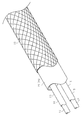
ここで、図1及び図2に示すように、上記の金属パイプ21の各屈曲部21bは、筒状の保護部材16にて覆われて保護されている。保護部材16は、絶縁性及び耐剪断性に優れた強化繊維が編み込まれて構成され、可撓性を有する。
本実施形態では、保護部材16は、金属パイプ21の長さ方向において部分的に設けられている。詳述すると、保護部材16は、金属パイプ21の2つの屈曲部21bにそれぞれ対応して、2つ設けられている。各保護部材16は、各屈曲部21bを覆うとともに、各屈曲部21bから直線部21a及び上方延出部21cを覆うように金属パイプ21の長さ方向に延びている。そして、各保護部材16の両端部は、粘着テープTの巻回によって、金属パイプ21の外周面に固定されている。
保護部材16を構成する強化繊維としては、例えば、パラ系アラミド繊維、ポリアリレート繊維、PBO(ポリパラフェニレンベンゾビスオキサゾール)繊維、PET(ポリエチレンテレフタレート)繊維、超高分子量ポリエチレン繊維、PEI(ポリエーテルイミド)繊維、ガラス繊維、セラミック繊維等が挙げられ、これらの内の1種類または複数種類を、保護部材16に要求される物性に応じて用いることが好ましい。本実施形態では、保護部材16はパラ系アラミド繊維の1種類で構成されている。
次に、本実施形態の作用について説明する。
各高圧電線13,14をまとめて包囲する金属パイプ21は、例えばパラ系アラミド繊維よりなる強化繊維で構成された耐衝撃性(特に耐剪断性)に優れる保護部材16によって外周が被覆されている。このため、車両衝突時の衝撃によって、例え金属パイプ21が破損したとしても、各高圧電線13,14の芯線17同士が直接的に接触、または、金属パイプ21の破断片やそれ以外の車両構成部品等、何らかの導体を介して導通されるといったことが抑制される。また、保護部材16は絶縁性を有するため、各高圧電線13,14の芯線17同士が保護部材16を介して導通してしまうことが抑制される。
各高圧電線13,14をまとめて包囲する金属パイプ21は、例えばパラ系アラミド繊維よりなる強化繊維で構成された耐衝撃性(特に耐剪断性)に優れる保護部材16によって外周が被覆されている。このため、車両衝突時の衝撃によって、例え金属パイプ21が破損したとしても、各高圧電線13,14の芯線17同士が直接的に接触、または、金属パイプ21の破断片やそれ以外の車両構成部品等、何らかの導体を介して導通されるといったことが抑制される。また、保護部材16は絶縁性を有するため、各高圧電線13,14の芯線17同士が保護部材16を介して導通してしまうことが抑制される。
次に、本実施形態の効果を記載する。
(1)ワイヤハーネス10は、絶縁性を有する強化繊維にて構成され電磁シールド部15(外装材)の一部を構成する金属パイプ21の外周を被覆する筒状の保護部材16を備える。この構成によれば、金属パイプ21の耐衝撃性が向上し、その結果、高圧バッテリ11に電気的に接続されたプラス・マイナスの高圧電線13,14同士の短絡を抑制できる。
(1)ワイヤハーネス10は、絶縁性を有する強化繊維にて構成され電磁シールド部15(外装材)の一部を構成する金属パイプ21の外周を被覆する筒状の保護部材16を備える。この構成によれば、金属パイプ21の耐衝撃性が向上し、その結果、高圧バッテリ11に電気的に接続されたプラス・マイナスの高圧電線13,14同士の短絡を抑制できる。
(2)金属パイプ21は、電線配索ラインに沿って屈曲する屈曲部21bを有し、保護部材16は、金属パイプ21の屈曲部21bを含む範囲に設けられており、図示した例では、保護部材16は、屈曲部21bと非屈曲部とを含むL字形範囲または所定長さ範囲に設けられている。この構成によれば、金属パイプ21の屈曲部21bでは径方向の肉厚が薄くなる等の理由から剛性が低くなる傾向があるため、その屈曲部21bを含む範囲に保護部材16を設けることで、金属パイプ21の破損を効果的に抑制できる。
(3)保護部材16を構成する強化繊維にアラミド繊維を用いることで、金属パイプ21の耐衝撃性を好適に向上させることができる。
なお、上記実施形態は、以下のように変更してもよい。
なお、上記実施形態は、以下のように変更してもよい。
・上記実施形態では、金属パイプ21の2つの屈曲部21bの各々に保護部材16を設けているが、これに限らず、2つの屈曲部21bのいずれか一方のみに保護部材16を設けてもよい。
・上記実施形態では、保護部材16は、金属パイプ21における少なくとも屈曲部21bを含む範囲に設けられたが、これに限らず、金属パイプ21における屈曲部21bを除く範囲(直線部21aや上方延出部21c)のみに設けてもよい。
・上記実施形態では、保護部材16は、金属パイプ21の長さ方向において部分的に設けられたが、これに限らず、金属パイプ21の長さ方向の全体に亘って保護部材16を設けてもよい。
・上記実施形態において、保護部材16を、高圧電源系のワイヤハーネス10を識別するための識別色で構成することが好ましい。これは、保護部材16を金属パイプ21の長さ方向の全体に設ける場合に特に有効である。
・上記実施形態では、金属パイプ21は2つの屈曲部21bを備えるが、これに限らず、1つ、又は3つ以上の屈曲部を備えた構成としてもよい。
・上記実施形態では、外装材としての電磁シールド部15において、金属パイプ21部分に保護部材16を設けたが、これに限らず、編組部材22の外周を被覆するように保護部材16を設けてもよい。この場合、編組部材22の外周を包囲するコルゲートチューブ等からなる外装材24を省略してもよく、また、外装材24をそのまま用いて該外装材24の内周側又は外周側に保護部材16を設けてもよい。
・上記実施形態では、外装材としての電磁シールド部15において、金属パイプ21部分に保護部材16を設けたが、これに限らず、編組部材22の外周を被覆するように保護部材16を設けてもよい。この場合、編組部材22の外周を包囲するコルゲートチューブ等からなる外装材24を省略してもよく、また、外装材24をそのまま用いて該外装材24の内周側又は外周側に保護部材16を設けてもよい。
・上記実施形態の電磁シールド部15は、金属パイプ21及び編組部材22から構成されているが、これに限らず、例えば、電磁シールド部15の長さ方向の全体を編組部材22で構成してもよい。
・上記実施形態では、各高圧電線13,14をまとめて包囲する外装材として電磁シールド部15を用いているが、これに限定されるものではなく、電磁シールド部15に代えて、シールド機能を有しない外装材(例えば、コルゲートチューブ等の合成樹脂製のパイプ材)を用いてもよい。
・上記実施形態のワイヤハーネス10では、プラス側高圧電線13及びマイナス側高圧電線14の2本の電線が電磁シールド部15に挿通される構成としたが、電磁シールド部15に挿通される電線の構成は、車両構成に応じて適宜変更してもよい。例えば、電磁シールド部15に挿通される電線として、低圧バッテリと各種低電圧機器(例えばランプ、カーオーディオ等)とを接続する低圧電線を追加した構成としてもよい。
・車両における高圧バッテリ11とインバータ12の配置関係は、上記実施形態に限定されるものではなく、車両構成に応じて適宜変更してもよい。また、上記実施形態では、高圧バッテリ11は、各高圧電線13,14を介してインバータ12と接続されるが、インバータ12以外の高電圧機器に接続される構成としてもよい。
・上記実施形態では、高圧バッテリ11とインバータ12とを繋ぐワイヤハーネス10に適用したが、これ以外に例えば、インバータ12と車輪駆動用モータとを繋ぐワイヤハーネスに適用してもよい。
・上記した実施形態並びに各変形例は適宜組み合わせてもよい。
次に、上記実施形態及び変形例から把握できる技術的思想を以下に追記する。
(イ)上記記載のワイヤハーネスにおいて、
前記外装材は、シールド機能を有する電磁シールド部にて構成されていることを特徴とするワイヤハーネス。
次に、上記実施形態及び変形例から把握できる技術的思想を以下に追記する。
(イ)上記記載のワイヤハーネスにおいて、
前記外装材は、シールド機能を有する電磁シールド部にて構成されていることを特徴とするワイヤハーネス。
この構成によれば、複数の電線をまとめて包囲する外装材がシールド機能を備えるため、各電線をノンシールド電線で構成することができ、各電線の構成を簡素化できる。
(ロ)上記記載のワイヤハーネスにおいて、
前記外装材は、少なくとも一部が車外に配置されており、その外装材の車外配置部位を保護部材が被覆していることを特徴とするワイヤハーネス。
(ロ)上記記載のワイヤハーネスにおいて、
前記外装材は、少なくとも一部が車外に配置されており、その外装材の車外配置部位を保護部材が被覆していることを特徴とするワイヤハーネス。
この構成によれば、衝撃を受けやすい外装材の車外配置部位が保護部材によって被覆されるため、外装材の破損を効果的に抑制できる。
本発明がその技術的思想から逸脱しない範囲で他の特有の形態で具体化されてもよいということは当業者にとって明らかであろう。例えば、実施形態(あるいはその1つ又は複数の態様)において説明した部品のうちの一部を省略したり、いくつかの部品を組合せてもよい。本発明の範囲は、添付の請求の範囲を参照して、請求の範囲が権利を与えられる均等物の全範囲と共に確定されるべきである。
本発明がその技術的思想から逸脱しない範囲で他の特有の形態で具体化されてもよいということは当業者にとって明らかであろう。例えば、実施形態(あるいはその1つ又は複数の態様)において説明した部品のうちの一部を省略したり、いくつかの部品を組合せてもよい。本発明の範囲は、添付の請求の範囲を参照して、請求の範囲が権利を与えられる均等物の全範囲と共に確定されるべきである。
10…ワイヤハーネス
11…高圧バッテリ
13…プラス側高圧電線
14…マイナス側高圧電線
15…電磁シールド部(外装材)
16…保護部材
21…外装材としての電磁シールド部の一部を構成する金属パイプ
21b…屈曲部
22…外装材としての電磁シールド部の一部を構成する編組部材
11…高圧バッテリ
13…プラス側高圧電線
14…マイナス側高圧電線
15…電磁シールド部(外装材)
16…保護部材
21…外装材としての電磁シールド部の一部を構成する金属パイプ
21b…屈曲部
22…外装材としての電磁シールド部の一部を構成する編組部材
Claims (3)
- 車載の高圧バッテリに電気的に接続されたプラス・マイナスの2本の高圧電線を含む複数の電線と、
前記複数の電線をまとめて包囲する筒状の外装材と
を備えたワイヤハーネスであって、
絶縁性を有する強化繊維にて構成され前記外装材の外周を被覆する筒状の保護部材を備えたことを特徴とするワイヤハーネス。 - 請求項1に記載のワイヤハーネスにおいて、
前記外装材は、電線配索ラインに沿って屈曲する屈曲部を有し、
前記保護部材は、少なくとも前記外装材の前記屈曲部を含む範囲に設けられていることを特徴とするワイヤハーネス。 - 請求項1又は2に記載のワイヤハーネスにおいて、
前記保護部材の前記強化繊維は、アラミド繊維であることを特徴とするワイヤハーネス。
Priority Applications (3)
| Application Number | Priority Date | Filing Date | Title |
|---|---|---|---|
| DE112017006362.0T DE112017006362T5 (de) | 2016-12-19 | 2017-12-05 | Kabelstrang |
| US16/465,889 US10569723B2 (en) | 2016-12-19 | 2017-12-05 | Wire harness with tube-shaped reinforced fiber cover |
| CN201780078050.3A CN110088849B (zh) | 2016-12-19 | 2017-12-05 | 线束 |
Applications Claiming Priority (2)
| Application Number | Priority Date | Filing Date | Title |
|---|---|---|---|
| JP2016-245812 | 2016-12-19 | ||
| JP2016245812A JP6686864B2 (ja) | 2016-12-19 | 2016-12-19 | ワイヤハーネス |
Publications (1)
| Publication Number | Publication Date |
|---|---|
| WO2018116809A1 true WO2018116809A1 (ja) | 2018-06-28 |
Family
ID=62626223
Family Applications (1)
| Application Number | Title | Priority Date | Filing Date |
|---|---|---|---|
| PCT/JP2017/043573 Ceased WO2018116809A1 (ja) | 2016-12-19 | 2017-12-05 | ワイヤハーネス |
Country Status (5)
| Country | Link |
|---|---|
| US (1) | US10569723B2 (ja) |
| JP (1) | JP6686864B2 (ja) |
| CN (1) | CN110088849B (ja) |
| DE (1) | DE112017006362T5 (ja) |
| WO (1) | WO2018116809A1 (ja) |
Families Citing this family (4)
| Publication number | Priority date | Publication date | Assignee | Title |
|---|---|---|---|---|
| JP6686864B2 (ja) * | 2016-12-19 | 2020-04-22 | 住友電装株式会社 | ワイヤハーネス |
| JP2020149781A (ja) * | 2019-03-11 | 2020-09-17 | 株式会社オートネットワーク技術研究所 | ワイヤハーネス |
| JP7622538B2 (ja) | 2021-04-27 | 2025-01-28 | 株式会社オートネットワーク技術研究所 | ワイヤーハーネス |
| DE102024125327A1 (de) | 2024-09-04 | 2026-03-05 | Weinert Industries Ag | Hochspannungstaugliches Lichtwellenleiterkabel und Kabelkonfektion sowie Hochspannungskonstruktion und Herstellungsverfahren für das Lichtwellenleiterkabel |
Citations (4)
| Publication number | Priority date | Publication date | Assignee | Title |
|---|---|---|---|---|
| JP3071579U (ja) * | 2000-03-08 | 2000-09-14 | エス・ディ・ケイ株式会社 | コード |
| JP2009107408A (ja) * | 2007-10-26 | 2009-05-21 | Toyota Industries Corp | クラッシュボックスとその製造方法 |
| JP2010097851A (ja) * | 2008-10-17 | 2010-04-30 | Sumitomo Electric Ind Ltd | 細径同軸ケーブルハーネス及びその接続構造 |
| JP2015183303A (ja) * | 2014-03-20 | 2015-10-22 | 村田機械株式会社 | ブレイダー及び筒体 |
Family Cites Families (29)
| Publication number | Priority date | Publication date | Assignee | Title |
|---|---|---|---|---|
| JP4146316B2 (ja) * | 2003-09-02 | 2008-09-10 | 矢崎総業株式会社 | プロテクタ |
| WO2006118273A1 (ja) * | 2005-04-28 | 2006-11-09 | Autonetworks Technologies, Ltd. | 配電体 |
| US7530847B2 (en) * | 2006-12-08 | 2009-05-12 | Caterpillar Inc. | Impact-resistant, high-strength, braided wiring harness |
| JP5293644B2 (ja) * | 2010-03-02 | 2013-09-18 | 住友電装株式会社 | ワイヤハーネスの配索構造 |
| JP5691642B2 (ja) * | 2011-02-28 | 2015-04-01 | 株式会社オートネットワーク技術研究所 | シールド導電体 |
| JP5935184B2 (ja) * | 2011-07-21 | 2016-06-15 | 矢崎総業株式会社 | 自動車用高圧ワイヤハーネス及びこの製造方法 |
| JP5768618B2 (ja) * | 2011-09-21 | 2015-08-26 | 住友電装株式会社 | ワイヤハーネスの端末防水構造 |
| JP5884133B2 (ja) * | 2011-11-07 | 2016-03-15 | 矢崎総業株式会社 | 自動車用高圧ワイヤハーネス |
| JP5986812B2 (ja) * | 2011-11-21 | 2016-09-06 | 矢崎総業株式会社 | ワイヤハーネス |
| JP5957779B2 (ja) * | 2011-11-30 | 2016-07-27 | 矢崎総業株式会社 | ワイヤハーネス |
| JP5803663B2 (ja) * | 2011-12-26 | 2015-11-04 | 株式会社オートネットワーク技術研究所 | 電線保護パイプ及びワイヤハーネス |
| JP5803659B2 (ja) * | 2011-12-26 | 2015-11-04 | 株式会社オートネットワーク技術研究所 | 電線保護パイプ及びワイヤハーネス |
| JP5737222B2 (ja) * | 2012-05-22 | 2015-06-17 | 住友電装株式会社 | 防水カバー |
| JP5957783B2 (ja) * | 2012-09-03 | 2016-07-27 | 矢崎総業株式会社 | ワイヤハーネス |
| CN104718677B (zh) * | 2012-10-05 | 2017-06-27 | 住友电装株式会社 | 线束 |
| WO2014112157A1 (ja) * | 2013-01-16 | 2014-07-24 | 株式会社オートネットワーク技術研究所 | 硬化材料、ワイヤーハーネス及びその製造方法 |
| JP6145771B2 (ja) * | 2013-06-20 | 2017-06-14 | 矢崎総業株式会社 | ワイヤハーネス |
| JP6200238B2 (ja) * | 2013-08-20 | 2017-09-20 | 矢崎総業株式会社 | ワイヤハーネス |
| JP2015076900A (ja) * | 2013-10-04 | 2015-04-20 | 住友電装株式会社 | シールドパイプ |
| JP6086323B2 (ja) * | 2013-10-04 | 2017-03-01 | 住友電装株式会社 | シールドパイプ |
| CN103985463A (zh) * | 2014-05-26 | 2014-08-13 | 四川九洲线缆有限责任公司 | 一种高强度特种绕圈线 |
| JP6118773B2 (ja) | 2014-09-16 | 2017-04-19 | 矢崎総業株式会社 | ワイヤハーネス用の外装部材、及びワイヤハーネス |
| WO2016031814A1 (ja) * | 2014-08-25 | 2016-03-03 | 矢崎総業株式会社 | ワイヤハーネス用の外装部材、及びワイヤハーネス |
| JP6132216B2 (ja) * | 2015-07-03 | 2017-05-24 | 住友電装株式会社 | ワイヤーハーネス |
| JP6481861B2 (ja) * | 2015-11-10 | 2019-03-13 | 住友電装株式会社 | シールド導電路 |
| JP2018007378A (ja) * | 2016-06-30 | 2018-01-11 | 矢崎総業株式会社 | ワイヤハーネス |
| JP6437510B2 (ja) * | 2016-12-19 | 2018-12-12 | 株式会社オートネットワーク技術研究所 | ワイヤハーネス |
| JP6686864B2 (ja) * | 2016-12-19 | 2020-04-22 | 住友電装株式会社 | ワイヤハーネス |
| JP7136542B2 (ja) * | 2017-08-07 | 2022-09-13 | 矢崎総業株式会社 | ワイヤハーネス |
-
2016
- 2016-12-19 JP JP2016245812A patent/JP6686864B2/ja not_active Expired - Fee Related
-
2017
- 2017-12-05 US US16/465,889 patent/US10569723B2/en not_active Expired - Fee Related
- 2017-12-05 DE DE112017006362.0T patent/DE112017006362T5/de not_active Ceased
- 2017-12-05 WO PCT/JP2017/043573 patent/WO2018116809A1/ja not_active Ceased
- 2017-12-05 CN CN201780078050.3A patent/CN110088849B/zh not_active Expired - Fee Related
Patent Citations (4)
| Publication number | Priority date | Publication date | Assignee | Title |
|---|---|---|---|---|
| JP3071579U (ja) * | 2000-03-08 | 2000-09-14 | エス・ディ・ケイ株式会社 | コード |
| JP2009107408A (ja) * | 2007-10-26 | 2009-05-21 | Toyota Industries Corp | クラッシュボックスとその製造方法 |
| JP2010097851A (ja) * | 2008-10-17 | 2010-04-30 | Sumitomo Electric Ind Ltd | 細径同軸ケーブルハーネス及びその接続構造 |
| JP2015183303A (ja) * | 2014-03-20 | 2015-10-22 | 村田機械株式会社 | ブレイダー及び筒体 |
Also Published As
| Publication number | Publication date |
|---|---|
| DE112017006362T5 (de) | 2019-08-29 |
| JP6686864B2 (ja) | 2020-04-22 |
| JP2018101510A (ja) | 2018-06-28 |
| CN110088849A (zh) | 2019-08-02 |
| US10569723B2 (en) | 2020-02-25 |
| CN110088849B (zh) | 2020-09-08 |
| US20190299884A1 (en) | 2019-10-03 |
Similar Documents
| Publication | Publication Date | Title |
|---|---|---|
| JP6437510B2 (ja) | ワイヤハーネス | |
| US10124748B2 (en) | Vehicular high-voltage wire and wire harness | |
| US10723292B2 (en) | Vehicular high-voltage wire and wire harness | |
| JP6080350B2 (ja) | ワイヤハーネス | |
| WO2015125550A1 (ja) | 電線、及び、ワイヤーハーネス | |
| WO2018116809A1 (ja) | ワイヤハーネス | |
| WO2018147441A1 (ja) | 保護部材、車両用高圧電線、及びワイヤハーネス | |
| JP5906544B2 (ja) | ワイヤハーネス | |
| JP2018041714A (ja) | 車両用高圧電線及びワイヤハーネス | |
| US10622116B2 (en) | Conductive wire, shielding braided member, and wire harness | |
| CN113168940A (zh) | 线束 | |
| JP6642409B2 (ja) | ワイヤハーネスにおける保護部材の保持構造 | |
| JP6760234B2 (ja) | ワイヤハーネス | |
| WO2018180603A1 (ja) | ワイヤハーネス |
Legal Events
| Date | Code | Title | Description |
|---|---|---|---|
| 121 | Ep: the epo has been informed by wipo that ep was designated in this application |
Ref document number: 17882775 Country of ref document: EP Kind code of ref document: A1 |
|
| 122 | Ep: pct application non-entry in european phase |
Ref document number: 17882775 Country of ref document: EP Kind code of ref document: A1 |