WO2018110293A1 - 一体化成形体及びその製造方法 - Google Patents
一体化成形体及びその製造方法 Download PDFInfo
- Publication number
- WO2018110293A1 WO2018110293A1 PCT/JP2017/043037 JP2017043037W WO2018110293A1 WO 2018110293 A1 WO2018110293 A1 WO 2018110293A1 JP 2017043037 W JP2017043037 W JP 2017043037W WO 2018110293 A1 WO2018110293 A1 WO 2018110293A1
- Authority
- WO
- WIPO (PCT)
- Prior art keywords
- resin
- molded body
- integrated molded
- plate material
- plate
- Prior art date
Links
Images


Classifications
-
- B—PERFORMING OPERATIONS; TRANSPORTING
- B32—LAYERED PRODUCTS
- B32B—LAYERED PRODUCTS, i.e. PRODUCTS BUILT-UP OF STRATA OF FLAT OR NON-FLAT, e.g. CELLULAR OR HONEYCOMB, FORM
- B32B5/00—Layered products characterised by the non- homogeneity or physical structure, i.e. comprising a fibrous, filamentary, particulate or foam layer; Layered products characterised by having a layer differing constitutionally or physically in different parts
- B32B5/22—Layered products characterised by the non- homogeneity or physical structure, i.e. comprising a fibrous, filamentary, particulate or foam layer; Layered products characterised by having a layer differing constitutionally or physically in different parts characterised by the presence of two or more layers which are next to each other and are fibrous, filamentary, formed of particles or foamed
- B32B5/24—Layered products characterised by the non- homogeneity or physical structure, i.e. comprising a fibrous, filamentary, particulate or foam layer; Layered products characterised by having a layer differing constitutionally or physically in different parts characterised by the presence of two or more layers which are next to each other and are fibrous, filamentary, formed of particles or foamed one layer being a fibrous or filamentary layer
- B32B5/26—Layered products characterised by the non- homogeneity or physical structure, i.e. comprising a fibrous, filamentary, particulate or foam layer; Layered products characterised by having a layer differing constitutionally or physically in different parts characterised by the presence of two or more layers which are next to each other and are fibrous, filamentary, formed of particles or foamed one layer being a fibrous or filamentary layer another layer next to it also being fibrous or filamentary
-
- B—PERFORMING OPERATIONS; TRANSPORTING
- B29—WORKING OF PLASTICS; WORKING OF SUBSTANCES IN A PLASTIC STATE IN GENERAL
- B29C—SHAPING OR JOINING OF PLASTICS; SHAPING OF MATERIAL IN A PLASTIC STATE, NOT OTHERWISE PROVIDED FOR; AFTER-TREATMENT OF THE SHAPED PRODUCTS, e.g. REPAIRING
- B29C65/00—Joining or sealing of preformed parts, e.g. welding of plastics materials; Apparatus therefor
- B29C65/70—Joining or sealing of preformed parts, e.g. welding of plastics materials; Apparatus therefor by moulding
-
- B—PERFORMING OPERATIONS; TRANSPORTING
- B29—WORKING OF PLASTICS; WORKING OF SUBSTANCES IN A PLASTIC STATE IN GENERAL
- B29C—SHAPING OR JOINING OF PLASTICS; SHAPING OF MATERIAL IN A PLASTIC STATE, NOT OTHERWISE PROVIDED FOR; AFTER-TREATMENT OF THE SHAPED PRODUCTS, e.g. REPAIRING
- B29C45/00—Injection moulding, i.e. forcing the required volume of moulding material through a nozzle into a closed mould; Apparatus therefor
- B29C45/14—Injection moulding, i.e. forcing the required volume of moulding material through a nozzle into a closed mould; Apparatus therefor incorporating preformed parts or layers, e.g. injection moulding around inserts or for coating articles
- B29C45/14336—Coating a portion of the article, e.g. the edge of the article
- B29C45/14377—Coating a portion of the article, e.g. the edge of the article using an additional insert, e.g. a fastening element
-
- B—PERFORMING OPERATIONS; TRANSPORTING
- B29—WORKING OF PLASTICS; WORKING OF SUBSTANCES IN A PLASTIC STATE IN GENERAL
- B29C—SHAPING OR JOINING OF PLASTICS; SHAPING OF MATERIAL IN A PLASTIC STATE, NOT OTHERWISE PROVIDED FOR; AFTER-TREATMENT OF THE SHAPED PRODUCTS, e.g. REPAIRING
- B29C45/00—Injection moulding, i.e. forcing the required volume of moulding material through a nozzle into a closed mould; Apparatus therefor
- B29C45/14—Injection moulding, i.e. forcing the required volume of moulding material through a nozzle into a closed mould; Apparatus therefor incorporating preformed parts or layers, e.g. injection moulding around inserts or for coating articles
- B29C45/14065—Positioning or centering articles in the mould
-
- B—PERFORMING OPERATIONS; TRANSPORTING
- B29—WORKING OF PLASTICS; WORKING OF SUBSTANCES IN A PLASTIC STATE IN GENERAL
- B29C—SHAPING OR JOINING OF PLASTICS; SHAPING OF MATERIAL IN A PLASTIC STATE, NOT OTHERWISE PROVIDED FOR; AFTER-TREATMENT OF THE SHAPED PRODUCTS, e.g. REPAIRING
- B29C45/00—Injection moulding, i.e. forcing the required volume of moulding material through a nozzle into a closed mould; Apparatus therefor
- B29C45/14—Injection moulding, i.e. forcing the required volume of moulding material through a nozzle into a closed mould; Apparatus therefor incorporating preformed parts or layers, e.g. injection moulding around inserts or for coating articles
- B29C45/14467—Joining articles or parts of a single article
- B29C45/14508—Joining juxtaposed sheet-like articles, e.g. for making trim panels
-
- B—PERFORMING OPERATIONS; TRANSPORTING
- B29—WORKING OF PLASTICS; WORKING OF SUBSTANCES IN A PLASTIC STATE IN GENERAL
- B29C—SHAPING OR JOINING OF PLASTICS; SHAPING OF MATERIAL IN A PLASTIC STATE, NOT OTHERWISE PROVIDED FOR; AFTER-TREATMENT OF THE SHAPED PRODUCTS, e.g. REPAIRING
- B29C45/00—Injection moulding, i.e. forcing the required volume of moulding material through a nozzle into a closed mould; Apparatus therefor
- B29C45/14—Injection moulding, i.e. forcing the required volume of moulding material through a nozzle into a closed mould; Apparatus therefor incorporating preformed parts or layers, e.g. injection moulding around inserts or for coating articles
- B29C45/14778—Injection moulding, i.e. forcing the required volume of moulding material through a nozzle into a closed mould; Apparatus therefor incorporating preformed parts or layers, e.g. injection moulding around inserts or for coating articles the article consisting of a material with particular properties, e.g. porous, brittle
-
- B—PERFORMING OPERATIONS; TRANSPORTING
- B29—WORKING OF PLASTICS; WORKING OF SUBSTANCES IN A PLASTIC STATE IN GENERAL
- B29C—SHAPING OR JOINING OF PLASTICS; SHAPING OF MATERIAL IN A PLASTIC STATE, NOT OTHERWISE PROVIDED FOR; AFTER-TREATMENT OF THE SHAPED PRODUCTS, e.g. REPAIRING
- B29C45/00—Injection moulding, i.e. forcing the required volume of moulding material through a nozzle into a closed mould; Apparatus therefor
- B29C45/17—Component parts, details or accessories; Auxiliary operations
- B29C45/26—Moulds
-
- B—PERFORMING OPERATIONS; TRANSPORTING
- B32—LAYERED PRODUCTS
- B32B—LAYERED PRODUCTS, i.e. PRODUCTS BUILT-UP OF STRATA OF FLAT OR NON-FLAT, e.g. CELLULAR OR HONEYCOMB, FORM
- B32B15/00—Layered products comprising a layer of metal
- B32B15/04—Layered products comprising a layer of metal comprising metal as the main or only constituent of a layer, which is next to another layer of the same or of a different material
- B32B15/046—Layered products comprising a layer of metal comprising metal as the main or only constituent of a layer, which is next to another layer of the same or of a different material of foam
-
- B—PERFORMING OPERATIONS; TRANSPORTING
- B32—LAYERED PRODUCTS
- B32B—LAYERED PRODUCTS, i.e. PRODUCTS BUILT-UP OF STRATA OF FLAT OR NON-FLAT, e.g. CELLULAR OR HONEYCOMB, FORM
- B32B15/00—Layered products comprising a layer of metal
- B32B15/04—Layered products comprising a layer of metal comprising metal as the main or only constituent of a layer, which is next to another layer of the same or of a different material
- B32B15/08—Layered products comprising a layer of metal comprising metal as the main or only constituent of a layer, which is next to another layer of the same or of a different material of synthetic resin
- B32B15/082—Layered products comprising a layer of metal comprising metal as the main or only constituent of a layer, which is next to another layer of the same or of a different material of synthetic resin comprising vinyl resins; comprising acrylic resins
-
- B—PERFORMING OPERATIONS; TRANSPORTING
- B32—LAYERED PRODUCTS
- B32B—LAYERED PRODUCTS, i.e. PRODUCTS BUILT-UP OF STRATA OF FLAT OR NON-FLAT, e.g. CELLULAR OR HONEYCOMB, FORM
- B32B15/00—Layered products comprising a layer of metal
- B32B15/04—Layered products comprising a layer of metal comprising metal as the main or only constituent of a layer, which is next to another layer of the same or of a different material
- B32B15/08—Layered products comprising a layer of metal comprising metal as the main or only constituent of a layer, which is next to another layer of the same or of a different material of synthetic resin
- B32B15/085—Layered products comprising a layer of metal comprising metal as the main or only constituent of a layer, which is next to another layer of the same or of a different material of synthetic resin comprising polyolefins
-
- B—PERFORMING OPERATIONS; TRANSPORTING
- B32—LAYERED PRODUCTS
- B32B—LAYERED PRODUCTS, i.e. PRODUCTS BUILT-UP OF STRATA OF FLAT OR NON-FLAT, e.g. CELLULAR OR HONEYCOMB, FORM
- B32B15/00—Layered products comprising a layer of metal
- B32B15/04—Layered products comprising a layer of metal comprising metal as the main or only constituent of a layer, which is next to another layer of the same or of a different material
- B32B15/08—Layered products comprising a layer of metal comprising metal as the main or only constituent of a layer, which is next to another layer of the same or of a different material of synthetic resin
- B32B15/088—Layered products comprising a layer of metal comprising metal as the main or only constituent of a layer, which is next to another layer of the same or of a different material of synthetic resin comprising polyamides
-
- B—PERFORMING OPERATIONS; TRANSPORTING
- B32—LAYERED PRODUCTS
- B32B—LAYERED PRODUCTS, i.e. PRODUCTS BUILT-UP OF STRATA OF FLAT OR NON-FLAT, e.g. CELLULAR OR HONEYCOMB, FORM
- B32B15/00—Layered products comprising a layer of metal
- B32B15/04—Layered products comprising a layer of metal comprising metal as the main or only constituent of a layer, which is next to another layer of the same or of a different material
- B32B15/08—Layered products comprising a layer of metal comprising metal as the main or only constituent of a layer, which is next to another layer of the same or of a different material of synthetic resin
- B32B15/09—Layered products comprising a layer of metal comprising metal as the main or only constituent of a layer, which is next to another layer of the same or of a different material of synthetic resin comprising polyesters
-
- B—PERFORMING OPERATIONS; TRANSPORTING
- B32—LAYERED PRODUCTS
- B32B—LAYERED PRODUCTS, i.e. PRODUCTS BUILT-UP OF STRATA OF FLAT OR NON-FLAT, e.g. CELLULAR OR HONEYCOMB, FORM
- B32B15/00—Layered products comprising a layer of metal
- B32B15/04—Layered products comprising a layer of metal comprising metal as the main or only constituent of a layer, which is next to another layer of the same or of a different material
- B32B15/08—Layered products comprising a layer of metal comprising metal as the main or only constituent of a layer, which is next to another layer of the same or of a different material of synthetic resin
- B32B15/092—Layered products comprising a layer of metal comprising metal as the main or only constituent of a layer, which is next to another layer of the same or of a different material of synthetic resin comprising epoxy resins
-
- B—PERFORMING OPERATIONS; TRANSPORTING
- B32—LAYERED PRODUCTS
- B32B—LAYERED PRODUCTS, i.e. PRODUCTS BUILT-UP OF STRATA OF FLAT OR NON-FLAT, e.g. CELLULAR OR HONEYCOMB, FORM
- B32B15/00—Layered products comprising a layer of metal
- B32B15/04—Layered products comprising a layer of metal comprising metal as the main or only constituent of a layer, which is next to another layer of the same or of a different material
- B32B15/08—Layered products comprising a layer of metal comprising metal as the main or only constituent of a layer, which is next to another layer of the same or of a different material of synthetic resin
- B32B15/095—Layered products comprising a layer of metal comprising metal as the main or only constituent of a layer, which is next to another layer of the same or of a different material of synthetic resin comprising polyurethanes
-
- B—PERFORMING OPERATIONS; TRANSPORTING
- B32—LAYERED PRODUCTS
- B32B—LAYERED PRODUCTS, i.e. PRODUCTS BUILT-UP OF STRATA OF FLAT OR NON-FLAT, e.g. CELLULAR OR HONEYCOMB, FORM
- B32B15/00—Layered products comprising a layer of metal
- B32B15/04—Layered products comprising a layer of metal comprising metal as the main or only constituent of a layer, which is next to another layer of the same or of a different material
- B32B15/08—Layered products comprising a layer of metal comprising metal as the main or only constituent of a layer, which is next to another layer of the same or of a different material of synthetic resin
- B32B15/098—Layered products comprising a layer of metal comprising metal as the main or only constituent of a layer, which is next to another layer of the same or of a different material of synthetic resin comprising condensation resins of aldehydes, e.g. with phenols, ureas or melamines
-
- B—PERFORMING OPERATIONS; TRANSPORTING
- B32—LAYERED PRODUCTS
- B32B—LAYERED PRODUCTS, i.e. PRODUCTS BUILT-UP OF STRATA OF FLAT OR NON-FLAT, e.g. CELLULAR OR HONEYCOMB, FORM
- B32B15/00—Layered products comprising a layer of metal
- B32B15/14—Layered products comprising a layer of metal next to a fibrous or filamentary layer
-
- B—PERFORMING OPERATIONS; TRANSPORTING
- B32—LAYERED PRODUCTS
- B32B—LAYERED PRODUCTS, i.e. PRODUCTS BUILT-UP OF STRATA OF FLAT OR NON-FLAT, e.g. CELLULAR OR HONEYCOMB, FORM
- B32B15/00—Layered products comprising a layer of metal
- B32B15/18—Layered products comprising a layer of metal comprising iron or steel
-
- B—PERFORMING OPERATIONS; TRANSPORTING
- B32—LAYERED PRODUCTS
- B32B—LAYERED PRODUCTS, i.e. PRODUCTS BUILT-UP OF STRATA OF FLAT OR NON-FLAT, e.g. CELLULAR OR HONEYCOMB, FORM
- B32B15/00—Layered products comprising a layer of metal
- B32B15/20—Layered products comprising a layer of metal comprising aluminium or copper
-
- B—PERFORMING OPERATIONS; TRANSPORTING
- B32—LAYERED PRODUCTS
- B32B—LAYERED PRODUCTS, i.e. PRODUCTS BUILT-UP OF STRATA OF FLAT OR NON-FLAT, e.g. CELLULAR OR HONEYCOMB, FORM
- B32B27/00—Layered products comprising a layer of synthetic resin
- B32B27/06—Layered products comprising a layer of synthetic resin as the main or only constituent of a layer, which is next to another layer of the same or of a different material
- B32B27/065—Layered products comprising a layer of synthetic resin as the main or only constituent of a layer, which is next to another layer of the same or of a different material of foam
-
- B—PERFORMING OPERATIONS; TRANSPORTING
- B32—LAYERED PRODUCTS
- B32B—LAYERED PRODUCTS, i.e. PRODUCTS BUILT-UP OF STRATA OF FLAT OR NON-FLAT, e.g. CELLULAR OR HONEYCOMB, FORM
- B32B27/00—Layered products comprising a layer of synthetic resin
- B32B27/06—Layered products comprising a layer of synthetic resin as the main or only constituent of a layer, which is next to another layer of the same or of a different material
- B32B27/08—Layered products comprising a layer of synthetic resin as the main or only constituent of a layer, which is next to another layer of the same or of a different material of synthetic resin
-
- B—PERFORMING OPERATIONS; TRANSPORTING
- B32—LAYERED PRODUCTS
- B32B—LAYERED PRODUCTS, i.e. PRODUCTS BUILT-UP OF STRATA OF FLAT OR NON-FLAT, e.g. CELLULAR OR HONEYCOMB, FORM
- B32B27/00—Layered products comprising a layer of synthetic resin
- B32B27/18—Layered products comprising a layer of synthetic resin characterised by the use of special additives
- B32B27/20—Layered products comprising a layer of synthetic resin characterised by the use of special additives using fillers, pigments, thixotroping agents
-
- B—PERFORMING OPERATIONS; TRANSPORTING
- B32—LAYERED PRODUCTS
- B32B—LAYERED PRODUCTS, i.e. PRODUCTS BUILT-UP OF STRATA OF FLAT OR NON-FLAT, e.g. CELLULAR OR HONEYCOMB, FORM
- B32B27/00—Layered products comprising a layer of synthetic resin
- B32B27/28—Layered products comprising a layer of synthetic resin comprising synthetic resins not wholly covered by any one of the sub-groups B32B27/30 - B32B27/42
- B32B27/281—Layered products comprising a layer of synthetic resin comprising synthetic resins not wholly covered by any one of the sub-groups B32B27/30 - B32B27/42 comprising polyimides
-
- B—PERFORMING OPERATIONS; TRANSPORTING
- B32—LAYERED PRODUCTS
- B32B—LAYERED PRODUCTS, i.e. PRODUCTS BUILT-UP OF STRATA OF FLAT OR NON-FLAT, e.g. CELLULAR OR HONEYCOMB, FORM
- B32B27/00—Layered products comprising a layer of synthetic resin
- B32B27/28—Layered products comprising a layer of synthetic resin comprising synthetic resins not wholly covered by any one of the sub-groups B32B27/30 - B32B27/42
- B32B27/285—Layered products comprising a layer of synthetic resin comprising synthetic resins not wholly covered by any one of the sub-groups B32B27/30 - B32B27/42 comprising polyethers
-
- B—PERFORMING OPERATIONS; TRANSPORTING
- B32—LAYERED PRODUCTS
- B32B—LAYERED PRODUCTS, i.e. PRODUCTS BUILT-UP OF STRATA OF FLAT OR NON-FLAT, e.g. CELLULAR OR HONEYCOMB, FORM
- B32B27/00—Layered products comprising a layer of synthetic resin
- B32B27/28—Layered products comprising a layer of synthetic resin comprising synthetic resins not wholly covered by any one of the sub-groups B32B27/30 - B32B27/42
- B32B27/286—Layered products comprising a layer of synthetic resin comprising synthetic resins not wholly covered by any one of the sub-groups B32B27/30 - B32B27/42 comprising polysulphones; polysulfides
-
- B—PERFORMING OPERATIONS; TRANSPORTING
- B32—LAYERED PRODUCTS
- B32B—LAYERED PRODUCTS, i.e. PRODUCTS BUILT-UP OF STRATA OF FLAT OR NON-FLAT, e.g. CELLULAR OR HONEYCOMB, FORM
- B32B27/00—Layered products comprising a layer of synthetic resin
- B32B27/28—Layered products comprising a layer of synthetic resin comprising synthetic resins not wholly covered by any one of the sub-groups B32B27/30 - B32B27/42
- B32B27/288—Layered products comprising a layer of synthetic resin comprising synthetic resins not wholly covered by any one of the sub-groups B32B27/30 - B32B27/42 comprising polyketones
-
- B—PERFORMING OPERATIONS; TRANSPORTING
- B32—LAYERED PRODUCTS
- B32B—LAYERED PRODUCTS, i.e. PRODUCTS BUILT-UP OF STRATA OF FLAT OR NON-FLAT, e.g. CELLULAR OR HONEYCOMB, FORM
- B32B27/00—Layered products comprising a layer of synthetic resin
- B32B27/30—Layered products comprising a layer of synthetic resin comprising vinyl (co)polymers; comprising acrylic (co)polymers
- B32B27/302—Layered products comprising a layer of synthetic resin comprising vinyl (co)polymers; comprising acrylic (co)polymers comprising aromatic vinyl (co)polymers, e.g. styrenic (co)polymers
-
- B—PERFORMING OPERATIONS; TRANSPORTING
- B32—LAYERED PRODUCTS
- B32B—LAYERED PRODUCTS, i.e. PRODUCTS BUILT-UP OF STRATA OF FLAT OR NON-FLAT, e.g. CELLULAR OR HONEYCOMB, FORM
- B32B27/00—Layered products comprising a layer of synthetic resin
- B32B27/30—Layered products comprising a layer of synthetic resin comprising vinyl (co)polymers; comprising acrylic (co)polymers
- B32B27/304—Layered products comprising a layer of synthetic resin comprising vinyl (co)polymers; comprising acrylic (co)polymers comprising vinyl halide (co)polymers, e.g. PVC, PVDC, PVF, PVDF
-
- B—PERFORMING OPERATIONS; TRANSPORTING
- B32—LAYERED PRODUCTS
- B32B—LAYERED PRODUCTS, i.e. PRODUCTS BUILT-UP OF STRATA OF FLAT OR NON-FLAT, e.g. CELLULAR OR HONEYCOMB, FORM
- B32B27/00—Layered products comprising a layer of synthetic resin
- B32B27/30—Layered products comprising a layer of synthetic resin comprising vinyl (co)polymers; comprising acrylic (co)polymers
- B32B27/308—Layered products comprising a layer of synthetic resin comprising vinyl (co)polymers; comprising acrylic (co)polymers comprising acrylic (co)polymers
-
- B—PERFORMING OPERATIONS; TRANSPORTING
- B32—LAYERED PRODUCTS
- B32B—LAYERED PRODUCTS, i.e. PRODUCTS BUILT-UP OF STRATA OF FLAT OR NON-FLAT, e.g. CELLULAR OR HONEYCOMB, FORM
- B32B27/00—Layered products comprising a layer of synthetic resin
- B32B27/32—Layered products comprising a layer of synthetic resin comprising polyolefins
- B32B27/322—Layered products comprising a layer of synthetic resin comprising polyolefins comprising halogenated polyolefins, e.g. PTFE
-
- B—PERFORMING OPERATIONS; TRANSPORTING
- B32—LAYERED PRODUCTS
- B32B—LAYERED PRODUCTS, i.e. PRODUCTS BUILT-UP OF STRATA OF FLAT OR NON-FLAT, e.g. CELLULAR OR HONEYCOMB, FORM
- B32B27/00—Layered products comprising a layer of synthetic resin
- B32B27/34—Layered products comprising a layer of synthetic resin comprising polyamides
-
- B—PERFORMING OPERATIONS; TRANSPORTING
- B32—LAYERED PRODUCTS
- B32B—LAYERED PRODUCTS, i.e. PRODUCTS BUILT-UP OF STRATA OF FLAT OR NON-FLAT, e.g. CELLULAR OR HONEYCOMB, FORM
- B32B27/00—Layered products comprising a layer of synthetic resin
- B32B27/36—Layered products comprising a layer of synthetic resin comprising polyesters
- B32B27/365—Layered products comprising a layer of synthetic resin comprising polyesters comprising polycarbonates
-
- B—PERFORMING OPERATIONS; TRANSPORTING
- B32—LAYERED PRODUCTS
- B32B—LAYERED PRODUCTS, i.e. PRODUCTS BUILT-UP OF STRATA OF FLAT OR NON-FLAT, e.g. CELLULAR OR HONEYCOMB, FORM
- B32B27/00—Layered products comprising a layer of synthetic resin
- B32B27/38—Layered products comprising a layer of synthetic resin comprising epoxy resins
-
- B—PERFORMING OPERATIONS; TRANSPORTING
- B32—LAYERED PRODUCTS
- B32B—LAYERED PRODUCTS, i.e. PRODUCTS BUILT-UP OF STRATA OF FLAT OR NON-FLAT, e.g. CELLULAR OR HONEYCOMB, FORM
- B32B27/00—Layered products comprising a layer of synthetic resin
- B32B27/40—Layered products comprising a layer of synthetic resin comprising polyurethanes
-
- B—PERFORMING OPERATIONS; TRANSPORTING
- B32—LAYERED PRODUCTS
- B32B—LAYERED PRODUCTS, i.e. PRODUCTS BUILT-UP OF STRATA OF FLAT OR NON-FLAT, e.g. CELLULAR OR HONEYCOMB, FORM
- B32B27/00—Layered products comprising a layer of synthetic resin
- B32B27/42—Layered products comprising a layer of synthetic resin comprising condensation resins of aldehydes, e.g. with phenols, ureas or melamines
-
- B—PERFORMING OPERATIONS; TRANSPORTING
- B32—LAYERED PRODUCTS
- B32B—LAYERED PRODUCTS, i.e. PRODUCTS BUILT-UP OF STRATA OF FLAT OR NON-FLAT, e.g. CELLULAR OR HONEYCOMB, FORM
- B32B3/00—Layered products comprising a layer with external or internal discontinuities or unevennesses, or a layer of non-planar form; Layered products having particular features of form
- B32B3/02—Layered products comprising a layer with external or internal discontinuities or unevennesses, or a layer of non-planar form; Layered products having particular features of form characterised by features of form at particular places, e.g. in edge regions
- B32B3/04—Layered products comprising a layer with external or internal discontinuities or unevennesses, or a layer of non-planar form; Layered products having particular features of form characterised by features of form at particular places, e.g. in edge regions characterised by at least one layer folded at the edge, e.g. over another layer ; characterised by at least one layer enveloping or enclosing a material
-
- B—PERFORMING OPERATIONS; TRANSPORTING
- B32—LAYERED PRODUCTS
- B32B—LAYERED PRODUCTS, i.e. PRODUCTS BUILT-UP OF STRATA OF FLAT OR NON-FLAT, e.g. CELLULAR OR HONEYCOMB, FORM
- B32B5/00—Layered products characterised by the non- homogeneity or physical structure, i.e. comprising a fibrous, filamentary, particulate or foam layer; Layered products characterised by having a layer differing constitutionally or physically in different parts
- B32B5/02—Layered products characterised by the non- homogeneity or physical structure, i.e. comprising a fibrous, filamentary, particulate or foam layer; Layered products characterised by having a layer differing constitutionally or physically in different parts characterised by structural features of a fibrous or filamentary layer
-
- B—PERFORMING OPERATIONS; TRANSPORTING
- B32—LAYERED PRODUCTS
- B32B—LAYERED PRODUCTS, i.e. PRODUCTS BUILT-UP OF STRATA OF FLAT OR NON-FLAT, e.g. CELLULAR OR HONEYCOMB, FORM
- B32B5/00—Layered products characterised by the non- homogeneity or physical structure, i.e. comprising a fibrous, filamentary, particulate or foam layer; Layered products characterised by having a layer differing constitutionally or physically in different parts
- B32B5/18—Layered products characterised by the non- homogeneity or physical structure, i.e. comprising a fibrous, filamentary, particulate or foam layer; Layered products characterised by having a layer differing constitutionally or physically in different parts characterised by features of a layer of foamed material
-
- B—PERFORMING OPERATIONS; TRANSPORTING
- B32—LAYERED PRODUCTS
- B32B—LAYERED PRODUCTS, i.e. PRODUCTS BUILT-UP OF STRATA OF FLAT OR NON-FLAT, e.g. CELLULAR OR HONEYCOMB, FORM
- B32B5/00—Layered products characterised by the non- homogeneity or physical structure, i.e. comprising a fibrous, filamentary, particulate or foam layer; Layered products characterised by having a layer differing constitutionally or physically in different parts
- B32B5/22—Layered products characterised by the non- homogeneity or physical structure, i.e. comprising a fibrous, filamentary, particulate or foam layer; Layered products characterised by having a layer differing constitutionally or physically in different parts characterised by the presence of two or more layers which are next to each other and are fibrous, filamentary, formed of particles or foamed
- B32B5/24—Layered products characterised by the non- homogeneity or physical structure, i.e. comprising a fibrous, filamentary, particulate or foam layer; Layered products characterised by having a layer differing constitutionally or physically in different parts characterised by the presence of two or more layers which are next to each other and are fibrous, filamentary, formed of particles or foamed one layer being a fibrous or filamentary layer
- B32B5/245—Layered products characterised by the non- homogeneity or physical structure, i.e. comprising a fibrous, filamentary, particulate or foam layer; Layered products characterised by having a layer differing constitutionally or physically in different parts characterised by the presence of two or more layers which are next to each other and are fibrous, filamentary, formed of particles or foamed one layer being a fibrous or filamentary layer another layer next to it being a foam layer
-
- B—PERFORMING OPERATIONS; TRANSPORTING
- B32—LAYERED PRODUCTS
- B32B—LAYERED PRODUCTS, i.e. PRODUCTS BUILT-UP OF STRATA OF FLAT OR NON-FLAT, e.g. CELLULAR OR HONEYCOMB, FORM
- B32B7/00—Layered products characterised by the relation between layers; Layered products characterised by the relative orientation of features between layers, or by the relative values of a measurable parameter between layers, i.e. products comprising layers having different physical, chemical or physicochemical properties; Layered products characterised by the interconnection of layers
- B32B7/04—Interconnection of layers
- B32B7/12—Interconnection of layers using interposed adhesives or interposed materials with bonding properties
-
- B—PERFORMING OPERATIONS; TRANSPORTING
- B29—WORKING OF PLASTICS; WORKING OF SUBSTANCES IN A PLASTIC STATE IN GENERAL
- B29C—SHAPING OR JOINING OF PLASTICS; SHAPING OF MATERIAL IN A PLASTIC STATE, NOT OTHERWISE PROVIDED FOR; AFTER-TREATMENT OF THE SHAPED PRODUCTS, e.g. REPAIRING
- B29C45/00—Injection moulding, i.e. forcing the required volume of moulding material through a nozzle into a closed mould; Apparatus therefor
- B29C45/14—Injection moulding, i.e. forcing the required volume of moulding material through a nozzle into a closed mould; Apparatus therefor incorporating preformed parts or layers, e.g. injection moulding around inserts or for coating articles
- B29C45/14467—Joining articles or parts of a single article
- B29C2045/1454—Joining articles or parts of a single article injecting between inserts not being in contact with each other
-
- B—PERFORMING OPERATIONS; TRANSPORTING
- B29—WORKING OF PLASTICS; WORKING OF SUBSTANCES IN A PLASTIC STATE IN GENERAL
- B29K—INDEXING SCHEME ASSOCIATED WITH SUBCLASSES B29B, B29C OR B29D, RELATING TO MOULDING MATERIALS OR TO MATERIALS FOR MOULDS, REINFORCEMENTS, FILLERS OR PREFORMED PARTS, e.g. INSERTS
- B29K2077/00—Use of PA, i.e. polyamides, e.g. polyesteramides or derivatives thereof, as moulding material
-
- B—PERFORMING OPERATIONS; TRANSPORTING
- B29—WORKING OF PLASTICS; WORKING OF SUBSTANCES IN A PLASTIC STATE IN GENERAL
- B29K—INDEXING SCHEME ASSOCIATED WITH SUBCLASSES B29B, B29C OR B29D, RELATING TO MOULDING MATERIALS OR TO MATERIALS FOR MOULDS, REINFORCEMENTS, FILLERS OR PREFORMED PARTS, e.g. INSERTS
- B29K2309/00—Use of inorganic materials not provided for in groups B29K2303/00 - B29K2307/00, as reinforcement
- B29K2309/08—Glass
-
- B—PERFORMING OPERATIONS; TRANSPORTING
- B29—WORKING OF PLASTICS; WORKING OF SUBSTANCES IN A PLASTIC STATE IN GENERAL
- B29L—INDEXING SCHEME ASSOCIATED WITH SUBCLASS B29C, RELATING TO PARTICULAR ARTICLES
- B29L2012/00—Frames
-
- B—PERFORMING OPERATIONS; TRANSPORTING
- B29—WORKING OF PLASTICS; WORKING OF SUBSTANCES IN A PLASTIC STATE IN GENERAL
- B29L—INDEXING SCHEME ASSOCIATED WITH SUBCLASS B29C, RELATING TO PARTICULAR ARTICLES
- B29L2031/00—Other particular articles
- B29L2031/34—Electrical apparatus, e.g. sparking plugs or parts thereof
- B29L2031/3481—Housings or casings incorporating or embedding electric or electronic elements
-
- B—PERFORMING OPERATIONS; TRANSPORTING
- B32—LAYERED PRODUCTS
- B32B—LAYERED PRODUCTS, i.e. PRODUCTS BUILT-UP OF STRATA OF FLAT OR NON-FLAT, e.g. CELLULAR OR HONEYCOMB, FORM
- B32B2250/00—Layers arrangement
- B32B2250/02—2 layers
-
- B—PERFORMING OPERATIONS; TRANSPORTING
- B32—LAYERED PRODUCTS
- B32B—LAYERED PRODUCTS, i.e. PRODUCTS BUILT-UP OF STRATA OF FLAT OR NON-FLAT, e.g. CELLULAR OR HONEYCOMB, FORM
- B32B2260/00—Layered product comprising an impregnated, embedded, or bonded layer wherein the layer comprises an impregnation, embedding, or binder material
- B32B2260/02—Composition of the impregnated, bonded or embedded layer
- B32B2260/021—Fibrous or filamentary layer
-
- B—PERFORMING OPERATIONS; TRANSPORTING
- B32—LAYERED PRODUCTS
- B32B—LAYERED PRODUCTS, i.e. PRODUCTS BUILT-UP OF STRATA OF FLAT OR NON-FLAT, e.g. CELLULAR OR HONEYCOMB, FORM
- B32B2260/00—Layered product comprising an impregnated, embedded, or bonded layer wherein the layer comprises an impregnation, embedding, or binder material
- B32B2260/04—Impregnation, embedding, or binder material
- B32B2260/046—Synthetic resin
-
- B—PERFORMING OPERATIONS; TRANSPORTING
- B32—LAYERED PRODUCTS
- B32B—LAYERED PRODUCTS, i.e. PRODUCTS BUILT-UP OF STRATA OF FLAT OR NON-FLAT, e.g. CELLULAR OR HONEYCOMB, FORM
- B32B2262/00—Composition or structural features of fibres which form a fibrous or filamentary layer or are present as additives
- B32B2262/02—Synthetic macromolecular fibres
- B32B2262/0246—Acrylic resin fibres
-
- B—PERFORMING OPERATIONS; TRANSPORTING
- B32—LAYERED PRODUCTS
- B32B—LAYERED PRODUCTS, i.e. PRODUCTS BUILT-UP OF STRATA OF FLAT OR NON-FLAT, e.g. CELLULAR OR HONEYCOMB, FORM
- B32B2262/00—Composition or structural features of fibres which form a fibrous or filamentary layer or are present as additives
- B32B2262/02—Synthetic macromolecular fibres
- B32B2262/0253—Polyolefin fibres
-
- B—PERFORMING OPERATIONS; TRANSPORTING
- B32—LAYERED PRODUCTS
- B32B—LAYERED PRODUCTS, i.e. PRODUCTS BUILT-UP OF STRATA OF FLAT OR NON-FLAT, e.g. CELLULAR OR HONEYCOMB, FORM
- B32B2262/00—Composition or structural features of fibres which form a fibrous or filamentary layer or are present as additives
- B32B2262/02—Synthetic macromolecular fibres
- B32B2262/0261—Polyamide fibres
- B32B2262/0269—Aromatic polyamide fibres
-
- B—PERFORMING OPERATIONS; TRANSPORTING
- B32—LAYERED PRODUCTS
- B32B—LAYERED PRODUCTS, i.e. PRODUCTS BUILT-UP OF STRATA OF FLAT OR NON-FLAT, e.g. CELLULAR OR HONEYCOMB, FORM
- B32B2262/00—Composition or structural features of fibres which form a fibrous or filamentary layer or are present as additives
- B32B2262/02—Synthetic macromolecular fibres
- B32B2262/0276—Polyester fibres
-
- B—PERFORMING OPERATIONS; TRANSPORTING
- B32—LAYERED PRODUCTS
- B32B—LAYERED PRODUCTS, i.e. PRODUCTS BUILT-UP OF STRATA OF FLAT OR NON-FLAT, e.g. CELLULAR OR HONEYCOMB, FORM
- B32B2262/00—Composition or structural features of fibres which form a fibrous or filamentary layer or are present as additives
- B32B2262/04—Cellulosic plastic fibres, e.g. rayon
-
- B—PERFORMING OPERATIONS; TRANSPORTING
- B32—LAYERED PRODUCTS
- B32B—LAYERED PRODUCTS, i.e. PRODUCTS BUILT-UP OF STRATA OF FLAT OR NON-FLAT, e.g. CELLULAR OR HONEYCOMB, FORM
- B32B2262/00—Composition or structural features of fibres which form a fibrous or filamentary layer or are present as additives
- B32B2262/10—Inorganic fibres
- B32B2262/101—Glass fibres
-
- B—PERFORMING OPERATIONS; TRANSPORTING
- B32—LAYERED PRODUCTS
- B32B—LAYERED PRODUCTS, i.e. PRODUCTS BUILT-UP OF STRATA OF FLAT OR NON-FLAT, e.g. CELLULAR OR HONEYCOMB, FORM
- B32B2262/00—Composition or structural features of fibres which form a fibrous or filamentary layer or are present as additives
- B32B2262/10—Inorganic fibres
- B32B2262/105—Ceramic fibres
-
- B—PERFORMING OPERATIONS; TRANSPORTING
- B32—LAYERED PRODUCTS
- B32B—LAYERED PRODUCTS, i.e. PRODUCTS BUILT-UP OF STRATA OF FLAT OR NON-FLAT, e.g. CELLULAR OR HONEYCOMB, FORM
- B32B2262/00—Composition or structural features of fibres which form a fibrous or filamentary layer or are present as additives
- B32B2262/10—Inorganic fibres
- B32B2262/106—Carbon fibres, e.g. graphite fibres
-
- B—PERFORMING OPERATIONS; TRANSPORTING
- B32—LAYERED PRODUCTS
- B32B—LAYERED PRODUCTS, i.e. PRODUCTS BUILT-UP OF STRATA OF FLAT OR NON-FLAT, e.g. CELLULAR OR HONEYCOMB, FORM
- B32B2266/00—Composition of foam
- B32B2266/02—Organic
- B32B2266/0214—Materials belonging to B32B27/00
- B32B2266/0221—Vinyl resin
- B32B2266/0228—Aromatic vinyl resin, e.g. styrenic (co)polymers
-
- B—PERFORMING OPERATIONS; TRANSPORTING
- B32—LAYERED PRODUCTS
- B32B—LAYERED PRODUCTS, i.e. PRODUCTS BUILT-UP OF STRATA OF FLAT OR NON-FLAT, e.g. CELLULAR OR HONEYCOMB, FORM
- B32B2266/00—Composition of foam
- B32B2266/02—Organic
- B32B2266/0214—Materials belonging to B32B27/00
- B32B2266/0221—Vinyl resin
- B32B2266/0235—Vinyl halide, e.g. PVC, PVDC, PVF, PVDF
-
- B—PERFORMING OPERATIONS; TRANSPORTING
- B32—LAYERED PRODUCTS
- B32B—LAYERED PRODUCTS, i.e. PRODUCTS BUILT-UP OF STRATA OF FLAT OR NON-FLAT, e.g. CELLULAR OR HONEYCOMB, FORM
- B32B2266/00—Composition of foam
- B32B2266/02—Organic
- B32B2266/0214—Materials belonging to B32B27/00
- B32B2266/0242—Acrylic resin
-
- B—PERFORMING OPERATIONS; TRANSPORTING
- B32—LAYERED PRODUCTS
- B32B—LAYERED PRODUCTS, i.e. PRODUCTS BUILT-UP OF STRATA OF FLAT OR NON-FLAT, e.g. CELLULAR OR HONEYCOMB, FORM
- B32B2266/00—Composition of foam
- B32B2266/02—Organic
- B32B2266/0214—Materials belonging to B32B27/00
- B32B2266/025—Polyolefin
-
- B—PERFORMING OPERATIONS; TRANSPORTING
- B32—LAYERED PRODUCTS
- B32B—LAYERED PRODUCTS, i.e. PRODUCTS BUILT-UP OF STRATA OF FLAT OR NON-FLAT, e.g. CELLULAR OR HONEYCOMB, FORM
- B32B2266/00—Composition of foam
- B32B2266/02—Organic
- B32B2266/0214—Materials belonging to B32B27/00
- B32B2266/0278—Polyurethane
-
- B—PERFORMING OPERATIONS; TRANSPORTING
- B32—LAYERED PRODUCTS
- B32B—LAYERED PRODUCTS, i.e. PRODUCTS BUILT-UP OF STRATA OF FLAT OR NON-FLAT, e.g. CELLULAR OR HONEYCOMB, FORM
- B32B2266/00—Composition of foam
- B32B2266/02—Organic
- B32B2266/0214—Materials belonging to B32B27/00
- B32B2266/0285—Condensation resins of aldehydes, e.g. with phenols, ureas, melamines
-
- B—PERFORMING OPERATIONS; TRANSPORTING
- B32—LAYERED PRODUCTS
- B32B—LAYERED PRODUCTS, i.e. PRODUCTS BUILT-UP OF STRATA OF FLAT OR NON-FLAT, e.g. CELLULAR OR HONEYCOMB, FORM
- B32B2274/00—Thermoplastic elastomer material
-
- B—PERFORMING OPERATIONS; TRANSPORTING
- B32—LAYERED PRODUCTS
- B32B—LAYERED PRODUCTS, i.e. PRODUCTS BUILT-UP OF STRATA OF FLAT OR NON-FLAT, e.g. CELLULAR OR HONEYCOMB, FORM
- B32B2307/00—Properties of the layers or laminate
- B32B2307/50—Properties of the layers or laminate having particular mechanical properties
- B32B2307/538—Roughness
-
- B—PERFORMING OPERATIONS; TRANSPORTING
- B32—LAYERED PRODUCTS
- B32B—LAYERED PRODUCTS, i.e. PRODUCTS BUILT-UP OF STRATA OF FLAT OR NON-FLAT, e.g. CELLULAR OR HONEYCOMB, FORM
- B32B2439/00—Containers; Receptacles
- B32B2439/40—Closed containers
- B32B2439/62—Boxes, cartons, cases
-
- B—PERFORMING OPERATIONS; TRANSPORTING
- B32—LAYERED PRODUCTS
- B32B—LAYERED PRODUCTS, i.e. PRODUCTS BUILT-UP OF STRATA OF FLAT OR NON-FLAT, e.g. CELLULAR OR HONEYCOMB, FORM
- B32B2457/00—Electrical equipment
-
- B—PERFORMING OPERATIONS; TRANSPORTING
- B32—LAYERED PRODUCTS
- B32B—LAYERED PRODUCTS, i.e. PRODUCTS BUILT-UP OF STRATA OF FLAT OR NON-FLAT, e.g. CELLULAR OR HONEYCOMB, FORM
- B32B2605/00—Vehicles
- B32B2605/003—Interior finishings
-
- Y—GENERAL TAGGING OF NEW TECHNOLOGICAL DEVELOPMENTS; GENERAL TAGGING OF CROSS-SECTIONAL TECHNOLOGIES SPANNING OVER SEVERAL SECTIONS OF THE IPC; TECHNICAL SUBJECTS COVERED BY FORMER USPC CROSS-REFERENCE ART COLLECTIONS [XRACs] AND DIGESTS
- Y10—TECHNICAL SUBJECTS COVERED BY FORMER USPC
- Y10T—TECHNICAL SUBJECTS COVERED BY FORMER US CLASSIFICATION
- Y10T428/00—Stock material or miscellaneous articles
- Y10T428/24—Structurally defined web or sheet [e.g., overall dimension, etc.]
- Y10T428/24777—Edge feature
Definitions
- the present invention relates to a light-weight, high-strength, high-rigidity, and integrated manufacturing body suitable for applications that require thinning, such as personal computers, office automation equipment, mobile phones, and other parts, and a method for manufacturing the same.
- the fiber reinforced resin structure made of reinforced fiber and resin and another member such as a frame member are integrally joined and molded to reduce the size and weight. Sex is required.
- Patent Document 1 states that “a molten resin is applied to a first resin molded product, a second resin molded product, and a joint formed between the first resin molded product and the second resin molded product.
- the resin joined body to be injected and bonded is described, and the" joining portion is substantially centered on the downstream opening of the injection flow path and has an angle with the molten resin injection direction in the injection flow path.
- Patent Document 1 aims to join two resin molded products with a simple device with a small amount of injected resin, and aims to realize a thin and light weight and suppress warpage. There is room for improvement in the application to the formation of a molded body obtained by joining a plurality of members, and there is no suggestion regarding the configuration.
- Patent Document 2 states that “a plurality of divided pieces formed by injection molding a synthetic resin are integrated through a joint portion to form a primary hollow molded product, and this primary hollow molded product is attached to a molding die.
- a synthetic resin hollow molded product obtained by fusing the joint portion with a secondary molding portion formed by injection molding a synthetic resin ” is described, and“ the joint portion is formed by forced fitting ”
- the effect of “there is no resin leakage to the hollow portion side in the joint portion and the fracture strength of the joint portion is excellent” is disclosed.
- Patent Document 2 is configured so that the joint portion is not easily pulled out by force fitting, thereby increasing the molding pressure during secondary injection molding and deforming the mating portion of the joint portion.
- the main purpose is to create a gap and prevent resin leakage from the gap to the hollow part side of the molded product.
- Patent Document 3 describes “a configuration in which a plurality of resin parts are joined with a joining resin by forming a passage in a joint portion of a plurality of resin parts and filling the passage with a joining resin”. Furthermore, by “providing the protrusions on at least one resin part”, it is possible to prevent “the bonding resin from protruding out of the passage, and the appearance of the resin product does not deteriorate, and cracks In other words, it is possible to form a resin product that is less susceptible to cracking and poor bonding.
- Patent Document 3 is mainly intended to prevent cracks, cracks, and poor bonding, and to prevent the bonding resin from protruding, realizing a thin and light weight and suppressing warpage. There is room for improvement in the application to the formation of a joined molded body of a plurality of members for the purpose of doing, and there is no suggestion regarding the configuration.
- Patent Document 4 states that “a material made of a fiber reinforced thermoplastic resin, a heat made of a nonwoven fabric of a thermoplastic resin at an adhesive interface between the radio wave shielding material (a) and the radio wave transmission material (b)”.
- An integrated molded body having a plastic resin adhesive layer and fixing the radio wave shielding material (a) and the radio wave transmitting material (b) through the thermoplastic resin adhesive layer by outsert injection molding ” is described,“ An effect is disclosed in which an electronic device casing excellent in peeling strength and mass productivity of a joint portion can be obtained without deteriorating wireless communication performance while maintaining radio wave shielding.
- the radio wave transmitting material is a method of injecting and molding the material forming the material into a mold in which the radio wave shielding material is arranged, the amount of the injection resin increases, and the integrated molded body has a surface.
- the radio wave transmitting material is a method of injecting and molding the material forming the material into a mold in which the radio wave shielding material is arranged, the amount of the injection resin increases, and the integrated molded body has a surface.
- a plate material having a shape there is room for improvement with respect to warpage reduction due to thermal shrinkage of the resin.
- JP 2003-236877 A Japanese Patent Laid-Open No. 11-179758 JP 2000-272014 A JP 2008-34823 A
- An object of the present invention is to provide an integrated molded body that can reduce warpage and can be reduced in weight and thickness, and a method for manufacturing the same.
- the present invention employs the following means. That is, (1) In an integrated molded body in which a bonding resin (C) is interposed between a plate material (A) whose surface on one side is a design surface and a member (B), the plate material (A) is placed inside the member (B). And the member (B) are arranged so as to be separated from each other, and at least a part of the outer peripheral edge portion of the plate member (A) has a first joint portion that joins the joining resin (C), and The integrated molded body which has the area
- Integrated molded body. (9)
- the plate material (A) sandwiches both surfaces of the core layer with a skin layer including a member composed of at least one of a fiber reinforced resin member made of a reinforced fiber and a thermosetting resin and a metal member.
- thermoplastic resin layer (D) is further provided on the outer surface of the plate material (A), and the plate material (A) and the bonding resin (C) are interposed via the thermoplastic resin layer (D).
- the core layer has a step portion between the first joint portion of the plate (A), which is the porous base material, and a region other than the first joint portion, and the step portion
- the integrated molded body according to (9) or (10) having an inclined surface of 10 ° to 90 ° with respect to the in-plane direction of the plate material (A).
- a method for producing an integrally molded article having at least the following steps [1] and [2].
- the integrated molded body and the method for manufacturing the same According to the integrated molded body and the method for manufacturing the same according to the present invention, a plurality of structures are bonded with high bonding strength, the bonding boundary portion has good smoothness, and the molded body has a component member of a plate material. Even if it is, it can reduce warpage and realize light weight and thinning.
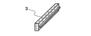
- FIG. 1 It is a perspective view which shows an example of the board
- FIG. 1 It is a perspective view which shows an example of the cross section in the thickness direction of the integrated molded object which concerns on this invention in case a board
- FIG. 10 is an enlarged cross-sectional view illustrating a joined state in the vicinity of an outer peripheral edge portion of the integrated molded body illustrated in FIG. 9. It is a perspective view which shows an example of the cross section in the thickness direction of the integrated molded object which concerns on this invention in case a board
- the structure of the integrated molded body according to the present invention is the integrated molded body in which the bonding resin (C) is interposed between the plate material (A) whose surface on one side is a design surface and the member (B). Inside, the plate member (A) and the member (B) are arranged so as to be separated from each other, and at least a part of the outer peripheral edge portion of the plate member (A) is bonded to the bonding resin (C). And having a region where the plate material (A), the member (B), and the bonding resin (C) are exposed on at least a part of the surface on the design surface side of the integrated molded body. is there.
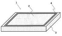
- the integrated molded body 1 according to the present invention is prepared by separately preparing a plate material (A) 2 and a member (B) 3 in advance and bonding them together with a bonding resin (C) 4. It is the structure to do.
- the bonding resin (C) 4 is bonded to the side surface portion and the flat surface portion of the outer peripheral edge portion 5 of the plate material (A) 2 (referred to as the first bonding portion), and further the bonding resin.
- (C) 4 and the member (B) 3 are joined (referred to as a second joining portion), and the joining resin (C) 4 is interposed between them.
- the bonding strength can be ensured even when the amount of the bonding resin is reduced, and the bonding resin (C) is also injected into the region of the conventional member (B) to be integrated with the plate material (A).
- the amount of resin can be greatly reduced, and it becomes possible to reduce warpage due to thermal shrinkage of the resin.
- the plate material (A) 2 is disposed inside the member (B) 3 so as to be separated.
- the plate material (A) 2 is arranged inside the member (B) 3.
- the plate material (A) 2 and the member (B) 3 are It does not have a site
- the injected bonding resin (C) 4 is easily inserted between the plate material (A) 2 and the member (B) 3, and the bonding strength of the integrated molded body 1 can be improved with a small amount of bonding resin. Further, it is possible to reduce the warpage due to the thermal contraction of the resin by reducing the amount of the bonding resin.
- the bonding resin (C) 4 is bonded to the plate material (A) 2 and the member (B) 3 by injection molding the bonding resin (C) 4 between the plate material (A) 2 and the member (B) 3.
- the bonding resin (C) 4 is interposed and integrated. This will be described later.
- the plate material (A) 2 and the bonding resin (C) 4 are bonded at the outer peripheral edge 5 of the plate material (A) 2.
- the outer peripheral edge 5 of the plate (A) 2 is preferably in the range of 0.1 to 15% from the end of the plate with respect to the length of one side of the plate (A) 2.
- a more preferred range is 0.5 to 10%, and a further more preferred range is 1 to 5%. If it is less than 0.1%, the bonding strength may decrease, and if it exceeds 15%, the amount of resin increases and the warpage during molding may deteriorate.
- the plate material (A) 2 has a surface shape having a side surface area smaller than the bottom area, and the thickness of the plate material (A) 2 which is the height of the side surface portion is 0 in the range of the bottom area of 50 to 10,000 cm 2. It is preferably in the range of 2 to 20 mm. More preferably, the bottom area is in the range of 100 to 2500 cm 2 and the plate thickness is in the range of 0.4 to 10 mm. More preferably, the bottom area is in the range of 300 to 1000 cm 2 and the plate thickness is in the range of 0.6 to 2 mm. is there.
- the area of the side surface is narrow, and a strong bonding strength is required to join the member (B) 3 to that part. is required. Even if it is such a form, even if it is a junction part of a narrow area, the member (B) 3 can be joined with strong intensity
- the structure which has the area
- the adhesive may ooze out, and then the oozed adhesive must be removed, and positioning between the members to be joined has a very high dimensional accuracy. Required.
- the bonding resin (C) 4 is interposed between the plate (A) 2 and the member (B) 3 to be bonded, and the bonding resin is interposed between these members.
- the upper side is the design surface side.
- the plate material (A) 2, the bonding resin (C) 4 and the member (B) 3 are arranged on the molding surface of the mold on the design surface at the time of molding, and the smoothness of the bonding boundary 6 is improved. To do.
- the first joint portion is formed over the entire circumference of the outer peripheral edge portion 5 of the plate material (A) 2. As shown in FIG. 3 or FIG. 4, the joint portion is formed over the entire circumference of the outer peripheral edge portion of the plate material (A) 2 and joined to the joining resin (C) 4, so that the integrated molded body 1 as a whole has high joint strength. Thinning can be realized.
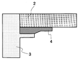
- the plate material (A) 2 and the member (B) 3 include a region 7 (FIG. 5) that overlaps with the bonding resin (C) 4. As shown in FIG. 5, an overlapping region 7 is formed by arranging the member (B) 3 so as to overlap in parallel below the plate material (A) 2 via the bonding resin (C) 4.
- the joint strength of the integrated molded body 1 can be improved.
- the bonding resin (C) 4 is preferably a thermoplastic resin. Thereby, the bonding resin (C) 4 can be easily inserted between the plate material (A) 2 and the member (B) 3 by injection molding, and the bonding strength of the integrated molded body 1 can be improved.
- a metal frame can be suitably used as the member (B) 3. Even when a metal frame is used as the member (B) 3, the bonding resin (C) 4 can be melted and bonded to the surface of the member (B) 3 which is a metal frame.
- metal frames examples include hot-rolled steel plates, stainless steel plates (SUS), single-layer plated steel plates obtained by plating a single layer of metal such as nickel, zinc, copper, etc.
- Various steel plates such as layer-plated steel plates, various metal plates such as aluminum plates and aluminum alloy plates can be used.
- the surface of the metal plate is electrolytically treated in a dichromic acid solution to form a single layer film made of chromium hydrated oxide, and the electrolytic chromium is made to form a two layer film made of chromium hydrated oxide and the lower layer made of chromium metal.
- Various chemical conversion treatments such as acid treatment, immersion chromic acid treatment, phosphoric acid chromic acid treatment, etching treatment with an alkali solution or acid solution, and anodizing treatment may be performed.
- the surface of the metal is finely formed by a method such as laser processing or sandpaper. It is possible to preferably use a method of forming an uneven surface and anchoring by resin penetration.
- primers and adhesives can be interposed on the surface of the metal plate for the purpose of improving the adhesion between the metal plate and the bonding resin (C) 4.
- Primers and adhesives include conventionally known aluminum, titanium, and silane coupling agents, acrylic resin adhesives, urethane resin adhesives, epoxy resin adhesives, and polyester resin adhesives. And so on.
- a fiber reinforced resin composed of a reinforced fiber and a resin can be preferably used as the member (B) 3.
- the member (B) 3 is a fiber reinforced resin containing a thermosetting resin, it has a structure bonded to the bonding resin (C) 4.
- the member (B) 3 is a fiber reinforced resin containing a thermoplastic resin
- a joining structure in which the thermoplastic resin of the member (B) 3 is melted and fixed to the joining resin (C) 4 is obtained.
- higher joint strength can be realized as the integrated molded body 1.
- the fusion bonded structure refers to a bonded structure in which mutual members are melted by heat and are fixed by cooling.
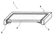
- the member (B) 3 is a frame member having an upright wall-shaped portion in at least a part of the member (B) 3.
- the integrated molded body 1 can be formed into a box-shaped body by including the standing wall-shaped portion 8 extending below the member (B) 3.
- a member composed of at least one of a fiber reinforced resin member made of a reinforced fiber and a thermosetting resin and a metal member can be suitably used for the plate material (A) 2.
- the bonding resin (C) is melted and bonded to the surface of the plate (A) 2 composed of at least one of a fiber reinforced resin member made of a reinforced fiber and a thermosetting resin and a metal member.
- a fiber reinforced resin member made of a reinforced fiber and a thermosetting resin and a metal member.
- other members are added to the plate material (A). Can be added.
- the metal member of the other member the same material and surface treatment method as those of the metal frame of the member (B) 3 described above can be used.
- the plate material (A) is a skin layer including a member composed of at least one of a fiber reinforced resin member and a metal member made of a reinforced fiber and a thermosetting resin, and both surfaces of the core layer. It is preferable that the core layer is selected from any one of a thermoplastic resin, a foam, and a porous substrate made of discontinuous fibers and a thermoplastic resin.
- the core layer 11 made of a thermoplastic resin or foam is composed of at least one of a fiber reinforced resin member made of a reinforced fiber and a thermosetting resin, and a metal member.
- swell to a thickness direction by a spring back can be used.
- the molded body containing the discontinuous fibers and the thermoplastic resin constituting the core layer 11 is heated and pressed above the softening point or melting point of the thermoplastic resin, and then the pressure is released to release the residual stress of the discontinuous fibers.
- a desired space can be formed in the core layer 11 by inflating with a restoring force to return to the original state, so-called springback. Thereby, the weight reduction and high rigidity of the integrated molded body 1 are realizable.
- the foam having pores used for the core layer 11 includes polyurethane resin, phenol resin, melamine resin, acrylic resin, polyethylene resin, polypropylene resin, polyvinyl chloride resin, polystyrene resin, acrylonitrile-butadiene-styrene (ABS) resin.
- a polyetherimide resin or a polymethacrylimide resin can be preferably used.
- a resin having an apparent density smaller than that of the skin layer in order to ensure lightness and in particular, a polyurethane resin, an acrylic resin, a polyethylene resin, a polypropylene resin, a polyetherimide resin, or a polymethacrylimide resin is used. It can be preferably used.
- thermoplastic resin layer (D) is further provided in the outer surface of the said board
- thermoplastic resin layer (D) 9 is attached in advance to the surface of the plate material (A) 2 to be bonded to the bonding resin (C) 4, and then the bonding resin (C) 4 Injection molding.
- plate material (A) 2 can implement
- the thermoplastic resin layer (D) 9 a thermoplastic resin film or a nonwoven fabric of a thermoplastic resin can be suitably used.
- this invention is the structure which has a fitting part into which bonding resin (C) 4 enters in a part of core layer 11 which consists of either a foam and the porous base material which consists of a discontinuous fiber and a thermoplastic resin. It is preferable that
- the bonding resin (C) 4 when the bonding resin (C) 4 is injection-molded, the bonding resin (C) 4 and the flat surface portion or the side surface portion of the skin layer 10 of the plate material (A) 2 are bonded.
- the bonding resin (C) 4 enters a part of the core layer 11 from the side surface portion of the plate material (A) 2 by injection molding pressure. This is because the region in the core layer 11 has a high porosity and has a structure in which the molten bonding resin (C) 4 easily enters.
- the bonding strength can be further increased by the anchor effect that the bonding resin (C) 4 enters the core layer 11.
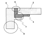
- plate material (A) 2 whose core layer 11 is a porous base material, and a 1st junction part It is also preferable to have a stepped portion 14 between the stepped portion 13 and the stepped portion 14 having an inclined surface with an angle ⁇ of 10 ° to 90 ° with respect to the in-plane direction of the plate (A) 2.
- the first joint portion 12 at the outer peripheral edge of the plate material (A) 2 is provided with a region having a thickness that is substantially horizontal to the in-plane direction of the main body, and the lower skin layer 10 is inclined at an angle ⁇ .
- the stepped portion 14 is provided. Thereby, the joining area of the 1st junction part 12 increases, and compared with the case where another structure is just joined to the side flat part of a sandwich structure, the junction area can be enlarged and joint strength is raised. An effect is obtained. Furthermore, the thickness of the plate material (A) 2 and the thickness of the bonding resin (C) 4 can be made the same, and the structure can be thinned with high bonding strength.
- the inclination angle of the skin layer 10 with respect to the in-plane direction of the plate material (A) 2 is preferably 10 to 90 °, more preferably 30 to 90 °, still more preferably 45 to 90 °. It is.
- the angle ⁇ at the vertical step portion is 90 °.
- the porosity of the porous base material in the first joint portion 12 is lower than the porosity of the porous base material in the region 13 other than the first joint portion.
- the core layer 11 is composed of discontinuous fibers and a thermoplastic resin, and a void having a size in the core layer 11 is formed.
- the plate material (A) 2 which is a sandwich structure is composed of a first joint 12 formed on at least a part of the outer peripheral edge and a region 13 other than the first joint, and other than the first joint.
- the porosity of the core layer 11 in the region 13 and the porosity of the core layer 11 in the first joint portion 12 are different from each other.
- thermoplastic resin which comprises board
- Any resin of the thermoplastic resin illustrated below can be used.
- polyester resins such as polyethylene terephthalate (PET) resin, polybutylene terephthalate (PBT) resin, polytrimethylene terephthalate (PTT) resin, polyethylene naphthalate (PEN resin), liquid crystal polyester resin, polyethylene (PE resin), polypropylene ( PP resin), polyolefin resins such as polybutylene resin, polyarylene sulfide resins such as polyoxymethylene (POM) resin, polyamide (PA) resin, polyphenylene sulfide (PPS) resin, polyketone (PK) resin, polyether ketone (PEK) ) Resin, polyether ether ketone (PEEK) resin, polyether ketone ketone (PEKK) resin, polyether nitrile (PEN) resin
- PET polyethylene terephthalate
- PBT
- crystalline resin such as liquid crystal polymer (LCP), styrene resin, polycarbonate (PC) resin, polymethyl methacrylate (PMMA) resin, polyvinyl chloride (PVC) resin, polyphenylene ether (PPE) resin, Amorphous resin such as polyimide (PI) resin, polyamideimide (PAI) resin, polyetherimide (PEI) resin, polysulfone (PSU) resin, polyethersulfone resin, polyarylate (PAR) resin, etc.
- LCP liquid crystal polymer
- PC polycarbonate
- PMMA polymethyl methacrylate
- PVC polyvinyl chloride
- PPE polyphenylene ether
- Amorphous resin such as polyimide (PI) resin, polyamideimide (PAI) resin, polyetherimide (PEI) resin, polysulfone (PSU) resin, polyethersulfone resin, polyarylate (PAR) resin, etc.
- thermoplastic resins such as polystyrene resins, polyolefin resins, polyurethane resins, polyester resins, polyamide resins, polybutadiene resins, polyisoprene resins, fluorine resins, and acrylonitrile resins ,this Mentioned thermoplastic resin selected from copolymers and modification products, etc. are.
- a polyolefin resin is preferable from the viewpoint of light weight of the obtained molded product
- a polyamide resin is preferable from the viewpoint of strength
- an amorphous material such as a polycarbonate resin, a styrene resin, and a modified polyphenylene ether resin from the viewpoint of surface appearance.
- Resin is preferable, polyarylene sulfide resin is preferable from the viewpoint of heat resistance, and polyether ether ketone resin is preferably used from the viewpoint of continuous use temperature.
- PAN polyacrylonitrile
- rayon-based, lignin-based, pitch-based carbon fiber such as glass, aramid resin, polyphenylene sulfide resin, polyester resin
- organic fibers such as acrylic resin, nylon resin, and polyethylene resin
- inorganic fibers such as silicon carbide and silicon nitride.
- glass fibers are preferably used from the viewpoint of improving the economical efficiency of the resulting molded article, and it is particularly preferable to use carbon fibers and glass fibers in combination from the balance of mechanical properties and economic efficiency.
- aramid fibers are preferably used from the viewpoint of improving the impact absorbability and formability of the obtained molded product, and it is particularly preferable to use carbon fibers and aramid fibers in combination from the balance of mechanical properties and impact absorbability.
- reinforcing fibers coated with a metal such as nickel, copper, ytterbium, etc. can also be used.
- PAN-based carbon fibers having excellent mechanical properties such as strength and elastic modulus can be used more preferably.
- thermosetting resins examples include unsaturated polyester resins, vinyl ester resins, epoxy resins, phenol (resole type) resins, urea / melamine resins, polyimide resins, maleimide resins, and benzoxazine resins. Resins and the like can be preferably used. For these, a resin in which two or more kinds are blended may be applied. Among these, an epoxy resin is particularly preferable from the viewpoint of mechanical properties of the molded body and heat resistance.
- the epoxy resin is preferably contained as a main component of the resin to be used in order to express its excellent mechanical properties, and specifically, it is preferably contained by 60% by weight or more per resin composition.
- the present invention is a method for producing an integrally molded body 1 having at least the following steps [1] and [2].
- [1] A step of disposing a plate material (A) 2 having a design surface on one side of the member (B) 3 at least partially apart from the member (B) 3 inside a frame-shaped member (B) 3 in a mold.
- [2] By injection molding the bonding resin (C) 4 in the gap between the plate material (A) 2 and the member (B) 3, the plate material (A) at least at the outer peripheral edge of the plate material (A) 2 And joining and integrating the member (B) 3
- the plate material (A) 2 shown in FIG. 1 and the member (B) 3 having the rectangular frame shape shown in FIG. 2 are separately formed in advance.
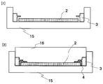
- the design surface side of the plate material (A) 2 is placed on the lower mold inside the member (B) 3 with at least partly separated from the member (B) 3. Position it on the 15th side.
- the upper mold 16 is set, and the bonding resin (C) 4 melted in the gap formed between the plate material (A) 2 and the member (B) 3 is injected. Mold. Thus, the bonding resin (C) 4 is joined and integrated with the member (B) 3 at the outer peripheral edge of the plate material (A) 2. Insert injection molding and outsert injection molding are preferably used.
- At least one part of the surface of the integrated molding 1 by the side of a design surface is made into a board
- the plate material (A) 2 and the member (B) 3 are arranged in the lower mold 15 with the surfaces being flush with each other, and the plate material (A) 2 and the member (B) 3 are arranged.
- the molten resin (C) 4 is injection-molded in the gap formed between the surfaces of the three members so that the surfaces of the three members are evenly exposed at the bottom surface of the mold. Designability can be improved.
- FIG. 14 shows one part of the member (B) 3 having four independent sides.
- the members (B) 3 are arranged on the outer sides of the four sides of the plate material (A) 2 with a certain gap, and then the bonding resin (C) 4 is injection-molded to obtain the plate material (A ) 2 and the four side independent members (B) 3 are joined and integrated with the joining resin (C) 4 interposed therebetween.
- the member (B) 3 By forming the member (B) 3 into four sides independent, the degree of freedom of molding of the integrated molded body is increased, and the bonding strength can be increased by arranging the bonding resin (C) 4 at the square positions. .
- the displacement (mm) in the thickness direction of the top plate (plate material (A)) was measured as follows. . There are four measurement points (9 points in total), the center of the top plate (plate material (A)), the four corners of the integrally formed body, and the center of each long side and short side. In addition, the measurement location other than the center part of a top plate (plate
- the warpage amount of the long side and the short side was derived from the remaining 8 displacements (mm) not including the displacement (mm) of the central portion of the top plate (plate material (A)).
- the amount of warpage of the long side first, the distance between the straight line connecting the two points at the end and the center point among the three displacements (mm) obtained from one long side was obtained. Next, the distance between the straight line connecting the two end points calculated from the other long side and the center point in the same manner is obtained, and the average value of the distances calculated from the two long sides is calculated as the amount of warpage of the long side. did. Similarly, the amount of warp on the short side was derived.
- the amount of warping of the diagonal line was derived from the displacement (mm) at the center of the top plate (plate material (A)) and the displacement (mm) at the four corners.
- the distance between the straight line connecting the two corners of the integrated molded body and the center point of the top plate (plate (A)) is two diagonal lines. The average value of these distances was taken as the amount of diagonal warpage.
- the joint was set at a 10 mm portion which was the midpoint of the measurement stroke.
- the difference between the maximum Y-direction displacement at the peak and the minimum Y-direction displacement at the bottom in the obtained roughness curve was defined as a step of the joint.
- Surfcom 480A manufactured by Tokyo Seimitsu Co., Ltd. was used as the surface roughness measuring instrument.
- plate material (A) and a member (B), and a member (B) and joining resin (C) was calculated
- each measurement location measured about the center part of each of two long sides of an integrated molded object, and made the average value the level
- the level difference of the obtained joint was evaluated according to the following criteria. Moreover, based on the determination result in the level
- the comprehensive evaluation of the integrated molded body is determined according to the following criteria. did. A and B are acceptable and C and D are unacceptable. A: Both of the two comprehensive evaluations are A determinations. B: Among the two comprehensive evaluations, C and D determinations are not included, and at least one is a B determination. C: Of the two comprehensive evaluations, D determination is included. When at least one is C judgment D: When at least one of two comprehensive evaluations is D judgment
- Material Composition Example 3 Preparation of Unidirectional Prepreg
- the PAN-based carbon fiber bundles obtained in Material Composition Example 1 are arranged in one direction in a sheet shape, and two epoxy resin films prepared in Material Composition Example 2 are both surfaces of carbon fibers. Then, the resin was impregnated with heat and pressure to prepare a unidirectional prepreg having a carbon fiber weight content of 70% and a thickness of 0.15 mm.
- thermoplastic Adhesive Film Pellets of polyamide resin (CM8000 manufactured by Toray Industries, Ltd., 4-copolymerized polyamide 6/66/610/12, melting point 130 ° C.) are press-molded to obtain a thickness of 0 A 05 mm thermoplastic adhesive film was obtained. This was used as a thermoplastic resin layer (D).
- This dry blend product was put in from a hopper of a twin screw extruder, melt kneaded in the extruder, and then extruded from a 400 mm wide T-die. Then, it cooled and solidified by taking up with a 60 degreeC chill roll, and obtained the polypropylene resin sheet.
- Aluminum plate (AL5052, thickness 1.25mm) was used as a metal member of a board
- CFRP Carbon Fiber Reinforced Plastic
- Aluminum Frame Material The aluminum material AL5052 was CNC processed to obtain an aluminum frame having the shape shown in FIG. This was used as an aluminum frame member for the member (B).
- Example 1 The unidirectional prepreg obtained in Material Composition Example 3 and the thermoplastic adhesive film obtained in Material Composition Example 4 were each adjusted to a size of 400 mm square, and then [unidirectional prepreg 0 ° / unidirectional prepreg 90 °. / Unidirectional prepreg 0 ° / unidirectional prepreg 90 ° / unidirectional prepreg 90 ° / unidirectional prepreg 0 ° / unidirectional prepreg 90 ° / unidirectional prepreg 0 ° / adhesive film].
- This laminate was sandwiched between release films and further sandwiched between tool plates.
- a spacer having a thickness of 1.25 mm was inserted between the tool plates for thickness adjustment.
- thermosetting CFRP plate with a thermoplastic adhesive film having a thickness of 1.25 mm. This was designated as plate material (A) 2 to which the thermoplastic resin layer (D) was adhered.
- thermoplastic adhesive processed into a size of 300 mm ⁇ 200 mm inside the frame member (member (B) 3) and separated from the frame member (member (B) 3).
- the CFRP plate with film (plate material (A) 2) was placed in alignment with the design surface side being the lower mold 15 side.
- the glass fiber reinforced nylon resin (joining resin (C) 4) of the material composition example 5 is injection-molded, and the top plate (plate material (A ) 2) and a four-sided standing wall (member (B) 3), an integrated molded body 1 was manufactured.
- FIG. 16 shows a cross section including the joint portion and the standing wall of the obtained integrated molded body 1. 3 and 16, the upper side of the drawing is the design surface side.
- the joint boundary part 3) had good smoothness. Further, the amount of warpage of the integrated molded body was small and good.
- the characteristics of the integrated molded body are summarized (Table 1).
- Example 2 CFRP plate (plate material (A) 2) with 300 mm ⁇ 200 mm ⁇ thickness 1.25 mm obtained in Example 1 and a CFRP frame (member (B) 3) shown in FIG. was used.
- the illustration of the thermoplastic adhesive film is omitted.
- the surface of the adhesion region of the CFRP frame was roughened with sandpaper.
- the CFRP plate with the thermoplastic adhesive film (plate (A) 2) is placed in the center of the lower mold 15 with the design surface side down, and the CFRP plate with the thermoplastic adhesive film.
- FIG. 17 shows a cross section including the joint portion and the standing wall of the obtained integrated molded body 1. 15 and 17, the upper side of the drawing is the design surface side.
- the CFRP plate with the thermoplastic adhesive film (plate material (A) 2) and the bonding resin (C) 4 of the integrated molded body, the bonding resin (C) 4 and the CFRP frame ( The joint boundary part of member (B) 3) had good smoothness. Further, the amount of warpage of the integrated molded body was small and good.
- Example 3 Using the unidirectional prepreg obtained in Material Composition Example 3 and the expanded polypropylene resin sheet obtained in Material Composition Example 6, each was adjusted to a size of 400 mm square, and then [unidirectional prepreg 0 ° / unidirectional prepreg 90 °. / Foamed polypropylene resin sheet / unidirectional prepreg 90 ° / unidirectional prepreg 0 °].
- This laminate was sandwiched between release films and further sandwiched between tool plates.
- a spacer having a thickness of 1.25 mm was inserted between the tool plates for thickness adjustment.
- the board surface After placing the tool plate on the board surface at a board surface temperature of 150 ° C., the board surface was closed and heated and pressed at 3 MPa. After 5 minutes from pressurization, the board surface was opened to obtain a foamed core layer sandwich structure (plate material (A) 2) having a flat plate shape with a thickness of 1.25 mm.
- a frame member (member (B) 3) made of a glass fiber reinforced nylon resin obtained in Example 1 and a foamed core layer sandwich structure processed into a size of 300 mm ⁇ 200 mm was used as an example. 1 was set in an injection mold in the same manner as in No. 1, and the mold was clamped. Then, a glass fiber reinforced nylon resin (bonding resin (C) 4) of Material Composition Example 5 was injected, and the top plate shown in FIG. An integrated molded body composed of four standing walls was manufactured. 9 and 10 show a cross section including the joint portion and the standing wall of the obtained integrated molded body. 3, 9, and 10, the upper side of the drawing is the design surface side.
- the jointed portion between the foam core layer sandwich structure (plate material (A) 2) and the bonding resin (C) 4 of the integrated molded body, the bonding resin (C) 4 and the frame member (member ( B) had good smoothness. Further, the amount of warpage of the integrated molded body was small and good.
- Example 4 Using the unidirectional prepreg obtained in Material Composition Example 3, the thermoplastic adhesive film obtained in Material Composition Example 4, and the polypropylene resin sheet obtained in Material Composition Example 10, each adjusted to a size of 400 mm square, The layers were laminated in the order of [unidirectional prepreg 0 ° / unidirectional prepreg 90 ° / polypropylene resin sheet / unidirectional prepreg 90 ° / unidirectional prepreg 0 ° / adhesive film]. This laminate was sandwiched between release films and further sandwiched between tool plates. Here, a spacer having a thickness of 1.25 mm was inserted between the tool plates for thickness adjustment.
- the rectangular frame-shaped frame member (member (B) 3) made of the glass fiber reinforced nylon resin obtained in Example 1 and the polypropylene resin core layer sandwich structure processed to a size of 300 mm ⁇ 200 mm were carried out.
- the glass fiber reinforced nylon resin (bonding resin (C) 4) of Material Composition Example 5 was injected, and the top plate shown in FIG. And a four-sided standing wall.
- FIG. 8 shows a cross section including the joint portion and the standing wall of the obtained integrated molded body. 3 and 8, the upper side of the drawing is the design surface side.
- the joint boundary part 3) had good smoothness. Further, the amount of warpage of the integrated molded body was small and good.
- Example 5 The unidirectional prepreg of material composition example 3, the thermoplastic adhesive film of material composition example 4, the carbon fiber mat of material composition example 8, and the polypropylene resin film of material composition example 9 were used. After adjusting these to a 400 mm square size, [unidirectional prepreg 0 ° / unidirectional prepreg 90 ° / polypropylene resin film / carbon fiber mat / polypropylene resin film / unidirectional prepreg 90 ° / unidirectional prepreg 0 ° / adhesive film ] Were laminated in the order.
- This laminate was sandwiched between release films and further sandwiched between tool plates.
- the surface of the plate was closed and heated and pressed at 3 MPa.
- the board surface was opened, and the tool plate was quickly placed on the board surface of a press molding machine having a board surface temperature of 40 ° C. and cooled and pressed at 3 MPa.
- the tool plate was taken out of the press molding machine to obtain a sandwich structure (plate material (A) 2) with a thermoplastic adhesive film having a plate thickness of 0.85 mm in which the core layer was impregnated with polypropylene resin.
- a spacer having a thickness of 1.25 mm is inserted between the obtained tool plates sandwiching the sandwich structure with the thermoplastic adhesive film, and the 0.4 mm thickness is only applied to the adhesive region of the sandwich structure with the thermoplastic adhesive film. Spacers were arranged, and the heating press and the cooling press were performed again with the same procedure and conditions. By stepping back only the core layer at the center of the sandwich structure with thermoplastic adhesive film, the outer periphery, which is the bonding area, has a thickness of 0.85 mm, and other areas are adjusted to a thickness of 1.25 mm.
- a sandwich structure with a thermoplastic adhesive film was obtained.
- the inclination angle ⁇ (°) of the skin layer 10 with respect to the in-plane direction of the sandwich structure (plate material (A) 2) with the thermoplastic adhesive film was 45 °.
- the glass fiber reinforced nylon resin (joining resin (C) 4) of Material Composition Example 5 was injection molded.
- 11 and 12 show a cross section including the joint portion and the standing wall of the obtained integrated molded body. 3, 11, and 12, the upper side of the drawing is the design surface side.
- a step-shaped sandwich structure with a thermoplastic adhesive film of the integrated molded body (plate material (A) 2) and the bonding boundary between the bonding resin (C) 4 and the bonding resin (C) 4 and the joining boundary part of the frame member (member (B) 3) had good smoothness. Further, the amount of warpage of the integrated molded body was small and good.
- Example 6 Only the surface on the bonding surface side of the aluminum plate (plate material (A) 2) of material composition example 11 was roughened with sandpaper, and then adjusted to a size of 300 mm ⁇ 200 mm.
- the frame member (member (B) 3) made of the glass fiber reinforced nylon resin obtained in Example 1 and the aluminum plate (plate material (A) 2) were made in the same manner as in Example 1.
- the glass fiber reinforced nylon resin (bonding resin (C) 4) of material composition example 5 was injection molded to obtain the top plate shown in FIG. An integrated molded body composed of standing walls was produced. 4 and 5 show a cross section including the joint portion and the standing wall of the obtained integrated molded body. 3, 4, and 5, the upper side of the drawing is the design surface side.
- Example 7 A CFRP plate (plate material (A) 2) with a thermoplastic adhesive film (thermoplastic resin layer (D) in the present invention) of 300 mm ⁇ 200 mm ⁇ thickness 1.25 mm obtained in Example 1, and aluminum of material composition example 13 A frame (member (B) 3) was used. The surface of the bonding area of the aluminum frame was roughened with sandpaper. Next, a CFRP plate with a thermoplastic adhesive film and four aluminum frames were set in an injection mold in the same manner as in Example 2 and clamped. Then, the glass fiber reinforced nylon of Material Composition Example 5 was used. A resin (bonding resin (C) 4) was injection-molded to produce an integrated molded body composed of a top plate and four side walls shown in FIG. FIG. 16 shows a cross section including the joint portion and the standing wall of the obtained integrated molded body. 15 and 16, the upper side of the drawing is the design surface side.
- the joint boundary part of 3) had good smoothness. Further, the amount of warpage of the integrated molded body was small and good.
- Example 8 CFRP plate (plate material (A) 2) with 301 mm ⁇ 201 mm ⁇ thickness of 1.25 mm obtained in Example 1 and a frame made of a glass fiber reinforced nylon resin obtained in Example 1
- the member (member (B) 3) was set in an injection mold in the same manner as in Example 1, and after clamping, the glass fiber reinforced nylon resin (bonding resin (C) 4) of Material Composition Example 5 was used.
- FIG. 19 shows a cross section including the joint portion and the standing wall of the obtained integrated molded body. 18 and 19, the lower side of the figure is the design surface side.
- the joint boundary part 3) had good smoothness. Further, the amount of warpage of the integrated molded body was small and good.
- the board surface After placing the tool plate on the board surface at a board surface temperature of 150 ° C., the board surface was closed and heated and pressed at 3 MPa. After 5 minutes from pressurization, the board surface was opened to obtain a CFRP plate (plate material (A) 2) having a thickness of 1.2 mm.
- FIG. 20 shows a cross section including the joint portion and the standing wall of the obtained integrated molded body. 18 and 20, the upper side of the drawing is the design surface side.
- the integrated molded body of the present invention can be effectively used for automobile interior and exterior, electrical / electronic equipment casings, bicycles, sporting goods structural materials, aircraft interior materials, transportation boxes, and the like.
Abstract
Description
(1)片側表面が意匠面である板材(A)と部材(B)との間に接合樹脂(C)が介在した一体化成形体において、前記部材(B)の内側に、前記板材(A)と前記部材(B)とが離間するように配置され、前記板材(A)の外周縁部の少なくとも一部の領域が前記接合樹脂(C)と接合する第1の接合部を有するとともに、前記一体化成形体の意匠面側の表面の少なくとも一部に、前記板材(A)、前記部材(B)、および前記接合樹脂(C)が露出する領域を有する一体化成形体。
(2)前記第1の接合部が、前記板材(A)の外周縁部全周にわたって形成されている(1)に記載の一体化成形体。
(3)前記板材(A)と前記部材(B)とが、前記接合樹脂(C)を介してオーバーラップする領域を含む(1)または(2)に記載の一体化成形体。
(4)前記接合樹脂(C)が熱可塑性樹脂である(1)~(3)のいずれかに記載の一体化成形体。
(5)前記部材(B)が金属製フレームである(1)~(4)のいずれかに記載の一体化成形体。
(6)前記部材(B)が強化繊維及び樹脂からなる繊維強化樹脂である(1)~(4)のいずれかに記載の一体化成形体。
(7)前記部材(B)が、前記部材(B)の少なくとも一部に立壁形状部を有するフレーム部材である(1)~(6)のいずれかに記載の一体化成形体。
(8)前記板材(A)は強化繊維と熱硬化性樹脂からなる繊維強化樹脂部材及び金属製部材の少なくとも1つから構成される部材を有する(1)~(7)のいずれかに記載の一体化成形体。
(9)前記板材(A)は、強化繊維と熱硬化性樹脂からなる繊維強化樹脂部材及び金属製部材のいずれか少なくとも1つから構成される部材を含むスキン層でコア層の両表面を挟んだサンドイッチ構造を有し、前記コア層が、熱可塑性樹脂、発泡体、および不連続繊維と熱可塑性樹脂からなる多孔質基材のいずれかから選択される(8)に記載の一体化成形体。
(10)前記板材(A)の外表面に熱可塑性樹脂層(D)が更に設けられているとともに、前記板材(A)と接合樹脂(C)とは前記熱可塑性樹脂層(D)を介して接合されている(8)または(9)に記載の一体化成形体。
(11)前記発泡体、および不連続繊維と熱可塑性樹脂からなる多孔質基材のいずれかからなる前記コア層の一部に、前記接合樹脂(C)が入り込む嵌入部を有する(9)または(10)に記載の一体化成形体。
(12)前記コア層が前記多孔質基材である前記板材(A)の前記第1の接合部と、該第1の接合部以外の領域との間に段差部を有し、前記段差部が前記板材(A)の面内方向に対して10°~90°の傾斜面を有する(9)または(10)に記載の一体化成形体。
(13)前記第1の接合部における前記多孔質基材の空隙率が、前記第1の接合部以外の領域における前記多孔質基材の空隙率よりも低い(12)に記載の一体化成形体。
(14)以下の工程[1]及び工程[2]を少なくとも有する一体化成形体の製造方法。
[1]フレーム形状を有する部材(B)の内側に、前記部材(B)と少なくとも一部を離間させて片側表面が意匠面である板材(A)を金型内に配置する工程
[2]前記板材(A)と前記部材(B)との空隙に接合樹脂(C)を射出成形することにより、少なくとも前記板材(A)の外周縁部で前記板材(A)と前記部材(B)とを接合一体化させる工程
(15)前記意匠面と反対側から前記空隙に接合樹脂(C)を射出成形することにより、前記意匠面側の一体化成形体表面の少なくとも一部を、前記板材(A)、前記部材(B)及び前記接合樹脂(C)が露出する領域とする(14)に記載の一体化成形体の製造方法。
本発明は、少なくとも以下の工程[1]及び工程[2]を有する一体化成形体1の製造方法である。
[1]フレーム形状を有する部材(B)3の内側に、前記部材(B)3と少なくとも一部を離間させて片側表面が意匠面である板材(A)2を金型内に配置する工程
[2]前記板材(A)2と前記部材(B)3との空隙の接合樹脂(C)4を射出成形することにより、少なくとも前記板材(A)2の外周縁部で前記板材(A)と前記部材(B)3とを接合一体化させる工程
まず、図1に示した板材(A)2と、図2に示した四角枠形状をした部材(B)3とを別々に予め成形しておく。
図14に、四辺独立した形態の部材(B)3の一つの部位を示す。図15に示すように、板材(A)2の四辺の外側にそれぞれ部材(B)3を一定の空隙を設けて配置し、その後に接合樹脂(C)4を射出成形することで板材(A)2と四辺独立した部材(B)3とが接合樹脂(C)4が介在した形で接合し一体化する。
箱型形状である一体化成形体の意匠面側を上にした状態で、次の通り天板(板材(A))の厚み方向の変位(mm)を測定した。測定点は天板(板材(A))の中央部と、一体化成形体の4つの角部と、各長辺、短辺の中央部の4点である(計9点)。なお、天板(板材(A))中央部以外の測定箇所は各長辺、短辺からそれぞれ2mm内側であり、測定には3次元測定器を用いた。
A:各反り量の合計が2.5mm未満
B:各反り量の合計が2.5mm以上3.0mm未満
C:各反り量の合計が3.0mm以上3.5mm未満
D:各反り量の合計が3.5mm以上
一体化化成形体の接合部において、表面粗さ測定器を用いて、接合境界線に対して垂直に接合部を横切るように表面粗さ計測定ヘッドを走査し、一体化成形体表面の粗さを測定(測定方法はJISB0633(2001)に準拠)した。板材(A)の厚み方向の変位(Y方向とする、単位:μm)と測定ストローク(単位:mm)とから粗さ曲線を求めた。測定条件として、測定ストロークは20mm、測定速度0.3mm/s、カットオフ値0.3mm、フィルタ種別はガウシアン、傾斜補正無し、を選択した。測定ストロークの中間点である10mmの部分に接合部をセットした。ここで、得られた粗さ曲線における最大の山頂のY方向変位と最小の谷底のY方向変位との差を接合部の段差とした。なお、本実施例では表面粗さ測定器として、(株)東京精密製サーフコム480Aを用いた。上述の方法により、板材(A)と接合樹脂(C)、板材(A)と部材(B)および部材(B)と接合樹脂(C)のそれぞれの接合部の段差を求めた。なお、各測定箇所は一体化成形体の2つの長辺のそれぞれの中央部について測定し、その平均値を接合部の段差とした。
(各接合部の段差における判定基準)
A:接合部の段差が8.0μm未満
B:接合部の段差が8.0μm以上1.2μm未満
C:接合部の段差が1.2μm以上
(接合部の段差における総合評価の判定基準)
A:全てがA判定の場合
B:C判定を含まず、少なくとも1つがB判定の場合
C:少なくとも1つがC判定の場合
一体化成形体の反り量、および一体化成形体の接合境界線の平滑性の2つの総合評価の判定結果に基づき、以下の基準で一体化成形体の総合評価を判定した。A、Bが合格であり、C、Dが不合格である。
A:2つの総合評価がいずれもA判定の場合
B:2つの総合評価のうち、C、D判定を含まず、少なくとも1つがB判定の場合
C:2つの総合評価のうち、D判定を含まず、少なくとも1つがC判定の場合
D:2つの総合評価のうち、少なくとも1つがD判定の場合
ポリアクリロニトリルを主成分とする重合体から紡糸、焼成処理を行い、総フィラメント数12000本の炭素繊維連続束を得た。この炭素繊維連続束に浸漬法によりサイジング剤を付与し、加熱空気中で乾燥しPAN系炭素繊維束を得た。このPAN系炭素繊維束の特性は次の通りであった。
単繊維径;7μm
単位長さ当たりの質量:0.83g/m
密度:1.8g/cm3
引張強度:4.0GPa
引張弾性率:235GPa
エポキシ樹脂(ベースレジン:ジシアンジアミド/ジクロロフェニルメチルウレア硬化系エポキシ樹脂)を、ナイフコーターを用いて離型紙上に塗布してエポキシ樹脂フィルムを得た。
材料組成例1で得たPAN系炭素繊維束をシート状に一方向に配列させ、材料組成例2で作製したエポキシ樹脂フィルム2枚を炭素繊維の両面から重ね、加熱加圧により樹脂を含浸させ、炭素繊維の重量含有率が70%、厚み0.15mmの一方向プリプレグを作製した。
ポリアミド樹脂(東レ(株)製CM8000、4元共重合ポリアミド6/66/610/12、融点130℃)のペレットを、プレス成形を行い、厚み0.05mmの熱可塑接着フィルムを得た。これを熱可塑性樹脂層(D)として使用した。
ガラス繊維強化ナイロン樹脂CM1011G-30(東レ(株)製、ナイロン6樹脂マトリックス、繊維重量含有率30%、融点225℃)を接合樹脂(C)として用いた。
ポリプロピレン樹脂ベースの発泡シート、厚み0.65mm、密度0.5g/cm3
カートリッジカッターを用いて、材料組成例1のPAN系炭素繊維束をカットし、繊維長6mmのチョップド炭素繊維束を得た。
界面活性剤(和光純薬工業(株)社製、「n-ドデシルベンゼンスルホン酸ナトリウム」(製品名))の1.5wt%水溶液100リットルを攪拌し、予め泡立てた分散液を作製した。この分散液に、材料組成例7で得られたチョップド炭素繊維束1を投入し、10分間撹拌した後、長さ400mm×幅400mmの抄紙面を有する抄紙機に流し込み、吸引により脱水後、150℃の温度で2時間乾燥し、炭素繊維からなる炭素繊維マットを得た。得られたマットは良好な分散状態であった。
無変性ポリプロピレン樹脂(プライムポリマー(株)社製、“プライムポリプロ”(登録商標)J105G、融点160℃)を90質量%と、酸変性ポリプロピレン樹脂(三井化学(株)社製、“アドマー” (登録商標) QE510、融点160℃)を10質量%用意し、これらをドライブレンドした。このドライブレンド品を二軸押出機のホッパーから投入し、押出機にて溶融混練した後、400mm幅のT字ダイから押出した。その後、60℃のチルロールで引き取ることによって冷却固化させ、ポリプロピレン樹脂フィルムを得た。
材料組成例9と同様にして、無変性ポリプロピレン樹脂(プライムポリマー(株)社製、“プライムポリプロ”(登録商標)J105G、融点160℃)を80質量%と、酸変性ポリプロピレン樹脂(三井化学(株)社製、“アドマー” (登録商標) QE510、融点160℃)を20質量%用意し、これらをドライブレンドした。このドライブレンド品を二軸押出機のホッパーから投入し、押出機にて溶融混練した後、400mm幅のT字ダイから押出した。その後、60℃のチルロールで引き取ることによって冷却固化させ、ポリプロピレン樹脂シートを得た。
アルミ板(AL5052、厚さ1.25mm)を板材(A)の金属製部材として使用した。
押出成形機を用いて、材料組成例1のPAN系炭素繊維束にフェノール樹脂を含浸させた、図14の形状をしたCFRP製フレーム材を得た。これを部材(B)のCFRP製フレーム部材として使用した。
AL5052の角材をCNC加工し、図14の形状をしたアルミ製フレームを得た。これを部材(B)のアルミ製フレーム部材として使用した。
材料組成例3で得た一方向プリプレグと、材料組成例4で得た熱可塑接着フィルムとを用いて、それぞれ400mm角のサイズに調整した後、[一方向プリプレグ0°/一方向プリプレグ90°/一方向プリプレグ0°/一方向プリプレグ90°/一方向プリプレグ90°/一方向プリプレグ0°/一方向プリプレグ90°/一方向プリプレグ0°/接着フィルム]の順序で積層した。この積層体を離型フィルムで挟み、さらにツール板で挟んだ。ここで、厚み調整としてツール板間に厚み1.25mmのスペーサを挿入した。盤面温度150℃の盤面の上にツール板を配置した後、盤面を閉じて3MPaで加熱プレスした。加圧から5分間経過した後、盤面を開き、厚み1.25mmの平板形状をした熱可塑接着フィルム付き熱硬化CFRP板を得た。これを熱可塑性樹脂層(D)が付着した板材(A)2とした。
実施例1で得た300mm×200mm×厚み1.25mmの熱可塑接着フィルム付きCFRP板(板材(A)2)と、材料組成例12の図14に示すCFRP製フレーム(部材(B)3)を用いた。熱可塑接着フィルムの図示は省略した。CFRP製フレームの接着領域の表面をサンドペーパーで荒らした。次に、図13に示すように、下金型15の中央に熱可塑接着フィルム付きCFRP板(板材(A)2)の意匠面側を下にして配置し、その熱可塑接着フィルム付きCFRP板(板材(A)2)の四辺の外側にそれぞれ4本のCFRP製フレーム(部材(B)3)を一定の空隙を設けて配置し、型締めを行った後、材料組成例5のガラス繊維強化ナイロン樹脂(接合樹脂(C)4)を射出成形して、図15に示す天板と4辺の立ち壁から構成された一体化成形体1を製造した。得られた一体化成形体1の接合部および立ち壁を含んだ断面を図17に示す。なお、図15および図17では、図の上方を意匠面側としている。
材料組成例3で得た一方向プリプレグと、材料組成例6で得た発泡ポリプロピレン樹脂シートとを用いて、それぞれ400mm角のサイズに調整した後、[一方向プリプレグ0°/一方向プリプレグ90°/発泡ポリプロピレン樹脂シート/一方向プリプレグ90°/一方向プリプレグ0°]の順序で積層した。この積層体を離型フィルムで挟み、さらにツール板で挟んだ。ここで、厚み調整としてツール板間に厚み1.25mmのスペーサを挿入した。盤面温度150℃の盤面の上にツール板を配置した後、盤面を閉じて3MPaで加熱プレスした。加圧から5分間経過した後、盤面を開き、厚み1.25mmの平板形状をした発泡コア層サンドイッチ構造体(板材(A)2)を得た。
材料組成例3で得た一方向プリプレグと、材料組成例4で得た熱可塑接着フィルムと、材料組成例10で得たポリプロピレン樹脂シートとを用いて、それぞれ400mm角のサイズに調整した後、[一方向プリプレグ0°/一方向プリプレグ90°/ポリプロピレン樹脂シート/一方向プリプレグ90°/一方向プリプレグ0°/接着フィルム]の順序で積層した。この積層体を離型フィルムで挟み、さらにツール板で挟んだ。ここで、厚み調整としてツール板間に厚み1.25mmのスペーサを挿入した。盤面温度160℃の盤面の上にツール板を配置した後、盤面を閉じて3MPaで加熱プレスした。加圧から5分間経過した後、盤面を開き、厚み1.25mmの平板形状をしたポリプロピレン樹脂コア層サンドイッチ構造体(板材(A)2)を得た。
材料組成例3の一方向プリプレグと、材料組成例4の熱可塑接着フィルムと、材料組成例8の炭素繊維マットと、材料組成例9のポリプロピレン樹脂フィルムとを用いた。これらを400mm角のサイズに調整した後、[一方向プリプレグ0°/一方向プリプレグ90°/ポリプロピレン樹脂フィルム/炭素繊維マット/ポリプロピレン樹脂フィルム/一方向プリプレグ90°/一方向プリプレグ0°/接着フィルム]の順序で積層した。
材料組成例11のアルミ板(板材(A)2)の接着面側の表面のみをサンドペーパーで荒らした後、300mm×200mmのサイズに調整した。次に、実施例1で得たガラス繊維強化ナイロン樹脂製の四角枠形状をしたフレーム部材(部材(B)3)と、アルミ板(板材(A)2)とを実施例1と同様にして射出成形金型内にセットし、型締めを行った後、材料組成例5のガラス繊維強化ナイロン樹脂(接合樹脂(C)4)を射出成形して、図3に示す天板と4辺の立ち壁から構成された一体化成形体を製造した。得られた一体化成形体の接合部および立ち壁を含んだ断面を図4および図5に示す。なお、図3、図4および図5では、図の上方を意匠面側としている。
実施例1で得た300mm×200mm×厚み1.25mmの熱可塑接着フィルム(本発明における熱可塑性樹脂層(D))付きCFRP板(板材(A)2)と、材料組成例13のアルミ製フレーム(部材(B)3)を用いた。アルミ製フレームの接着領域の表面をサンドペーパーで荒らした。次に、熱可塑接着フィルム付きCFRP板と、アルミ製フレーム4本を実施例2と同様にして射出成形金型内にセットし、型締めを行った後、材料組成例5のガラス繊維強化ナイロン樹脂(接合樹脂(C)4)を射出成形して、図15に示す天板と4辺の立ち壁から構成された一体化成形体を製造した。得られた一体化成形体の接合部および立ち壁を含んだ断面を図16に示す。なお、図15および図16では、図の上方を意匠面側としている。
実施例1で得た301mm×201mm×厚み1.25mmの熱可塑接着フィルム付きCFRP板(板材(A)2)と、実施例1で得たガラス繊維強化ナイロン樹脂製の四角枠形状をしたフレーム部材(部材(B)3)とを実施例1と同様にして射出成形金型内にセットし、型締めを行った後、材料組成例5のガラス繊維強化ナイロン樹脂(接合樹脂(C)4)を射出し、図18に示す天板と4辺の立ち壁から構成された一体化成形体を製造した。得られた一体化成形体の接合部および立ち壁を含んだ断面を図19に示す。なお、図18および図19では、図の下方を意匠面側としている。
材料組成例3で得た一方向プリプレグを用いて、400mm角のサイズに調整した後、[一方向プリプレグ0°/一方向プリプレグ90°/一方向プリプレグ0°/一方向プリプレグ90°/一方向プリプレグ90°/一方向プリプレグ0°/一方向プリプレグ90°/一方向プリプレグ0°]の順序で積層した。この積層体を離型フィルムで挟み、さらにツール板で挟んだ。ここで、厚み調整としてツール板間に厚み1.2mmのスペーサを挿入した。盤面温度150℃の盤面の上にツール板を配置した後、盤面を閉じて3MPaで加熱プレスした。加圧から5分間経過した後、盤面を開き、厚み1.2mmの平板形状をしたCFRP板(板材(A)2)を得た。

2 板材(A)
3 部材(B)
4 接合樹脂(C)
5 外周縁部
6 接合境界部
7 オーバーラップする領域
8 立壁形状部
9 熱可塑性樹脂層(D)
10 スキン層
11 コア層
12 第1の接合部
13 第1の接合部以外の領域
14 段差部
15 下金型
16 上金型
17 嵌入部
Claims (15)
- 片側表面が意匠面である板材(A)と部材(B)との間に接合樹脂(C)が介在した一体化成形体において、前記部材(B)の内側に、前記板材(A)と前記部材(B)とが離間するように配置され、前記板材(A)の外周縁部の少なくとも一部の領域が前記接合樹脂(C)と接合する第1の接合部を有するとともに、前記一体化成形体の意匠面側の表面の少なくとも一部に、前記板材(A)、前記部材(B)、および前記接合樹脂(C)が露出する領域を有する一体化成形体。
- 前記第1の接合部が、前記板材(A)の外周縁部全周にわたって形成されている請求項1に記載の一体化成形体。
- 前記板材(A)と前記部材(B)とが、前記接合樹脂(C)を介してオーバーラップする領域を含む請求項1または2に記載の一体化成形体。
- 前記接合樹脂(C)が熱可塑性樹脂である請求項1~3のいずれかに記載の一体化成形体。
- 前記部材(B)が金属製フレームである請求項1~4のいずれかに記載の一体化成形体。
- 前記部材(B)が強化繊維及び樹脂からなる繊維強化樹脂である請求項1~4のいずれかに記載の一体化成形体。
- 前記部材(B)が、前記部材(B)の少なくとも一部に立壁形状部を有するフレーム部材である請求項1~6のいずれかに記載の一体化成形体。
- 前記板材(A)は強化繊維と熱硬化性樹脂からなる繊維強化樹脂部材及び金属製部材の少なくとも1つから構成される部材を有する請求項1~7のいずれかに記載の一体化成形体。
- 前記板材(A)は、強化繊維と熱硬化性樹脂からなる繊維強化樹脂部材及び金属製部材のいずれか少なくとも1つから構成される部材を含むスキン層でコア層の両表面を挟んだサンドイッチ構造を有し、前記コア層が、熱可塑性樹脂、発泡体、および不連続繊維と熱可塑性樹脂からなる多孔質基材のいずれかから選択される請求項8に記載の一体化成形体。
- 前記板材(A)の外表面に熱可塑性樹脂層(D)が更に設けられているとともに、前記板材(A)と接合樹脂(C)とは前記熱可塑性樹脂層(D)を介して接合されている請求項8または9に記載の一体化成形体。
- 前記発泡体、および不連続繊維と熱可塑性樹脂からなる多孔質基材のいずれかからなる前記コア層の一部に、前記接合樹脂(C)が入り込む嵌入部を有する請求項9または10に記載の一体化成形体。
- 前記コア層が前記多孔質基材である前記板材(A)の前記第1の接合部と、該第1の接合部以外の領域との間に段差部を有し、前記段差部が前記板材(A)の面内方向に対して10°~90°の傾斜面を有する請求項9または10に記載の一体化成形体。
- 前記第1の接合部における前記多孔質基材の空隙率が、前記第1の接合部以外の領域における前記多孔質基材の空隙率よりも低い請求項12に記載の一体化成形体。
- 以下の工程[1]及び工程[2]を少なくとも有する一体化成形体の製造方法。
[1]フレーム形状を有する部材(B)の内側に、前記部材(B)と少なくとも一部を離間させて片側表面が意匠面である板材(A)を金型内に配置する工程
[2]前記板材(A)と前記部材(B)との空隙に接合樹脂(C)を射出成形することにより、少なくとも前記板材(A)の外周縁部で前記板材(A)と前記部材(B)とを接合一体化させる工程 - 前記意匠面と反対側から前記空隙に接合樹脂(C)を射出成形することにより、前記意匠面側の一体化成形体表面の少なくとも一部を、前記板材(A)、前記部材(B)及び前記接合樹脂(C)が露出する領域とする請求項14に記載の一体化成形体の製造方法。
Priority Applications (5)
| Application Number | Priority Date | Filing Date | Title |
|---|---|---|---|
| JP2017563142A JP6992512B2 (ja) | 2016-12-12 | 2017-11-30 | 一体化成形体及びその製造方法 |
| EP17881385.3A EP3552794A4 (en) | 2016-12-12 | 2017-11-30 | PRESSED BODY AND METHOD OF MANUFACTURING THEREOF |
| US16/468,198 US11110685B2 (en) | 2016-12-12 | 2017-11-30 | Integrally molded body and method of producing same |
| CN201780076002.0A CN110062687B (zh) | 2016-12-12 | 2017-11-30 | 一体化成型体及其制造方法 |
| KR1020197015405A KR20190093566A (ko) | 2016-12-12 | 2017-11-30 | 일체화 성형체 및 그의 제조 방법 |
Applications Claiming Priority (2)
| Application Number | Priority Date | Filing Date | Title |
|---|---|---|---|
| JP2016240064 | 2016-12-12 | ||
| JP2016-240064 | 2016-12-12 |
Publications (1)
| Publication Number | Publication Date |
|---|---|
| WO2018110293A1 true WO2018110293A1 (ja) | 2018-06-21 |
Family
ID=62559423
Family Applications (1)
| Application Number | Title | Priority Date | Filing Date |
|---|---|---|---|
| PCT/JP2017/043037 WO2018110293A1 (ja) | 2016-12-12 | 2017-11-30 | 一体化成形体及びその製造方法 |
Country Status (7)
| Country | Link |
|---|---|
| US (1) | US11110685B2 (ja) |
| EP (1) | EP3552794A4 (ja) |
| JP (1) | JP6992512B2 (ja) |
| KR (1) | KR20190093566A (ja) |
| CN (1) | CN110062687B (ja) |
| TW (1) | TWI781970B (ja) |
| WO (1) | WO2018110293A1 (ja) |
Cited By (7)
| Publication number | Priority date | Publication date | Assignee | Title |
|---|---|---|---|---|
| WO2019235299A1 (ja) * | 2018-06-07 | 2019-12-12 | 東レ株式会社 | 一体化成形体及びその製造方法 |
| JPWO2020202903A1 (ja) * | 2019-03-29 | 2020-10-08 | ||
| WO2021200008A1 (ja) * | 2020-03-31 | 2021-10-07 | 東レ株式会社 | 繊維強化プラスチック成形体 |
| US20220063246A1 (en) * | 2020-09-02 | 2022-03-03 | Hyundai Motor Company | Method for manufacturing a sandwich panel for a vehicle and a sandwich panel for a vehicle |
| JP7138826B1 (ja) * | 2022-03-08 | 2022-09-16 | 三菱電機株式会社 | 封孔処理された金属複合体および金型並びに封孔処理された金属複合体の製造方法 |
| US20220355518A1 (en) * | 2021-05-07 | 2022-11-10 | Microsoft Technology Licensing, Llc | Forming complex geometries using insert molding |
| JP7187653B1 (ja) * | 2021-12-21 | 2022-12-12 | 株式会社サカイヤ | クッション性を備え、加飾された成形樹脂製品およびその製造方法 |
Families Citing this family (9)
| Publication number | Priority date | Publication date | Assignee | Title |
|---|---|---|---|---|
| CN111989603B (zh) * | 2018-05-23 | 2023-04-04 | 松下知识产权经营株式会社 | 树脂部件保持构件、图像显示装置以及光扩散构件 |
| JP2022522666A (ja) * | 2019-03-05 | 2022-04-20 | エージーシー グラス ユーロップ | 車両用の成形ガラストリム要素 |
| EP3825116A1 (en) * | 2019-11-19 | 2021-05-26 | SABIC Global Technologies B.V. | Portable electronic device housings having laminate plates and sidewalls and methods of making the same |
| DE102020117430A1 (de) | 2020-07-02 | 2022-01-05 | Audi Ag | Sandwichbauteil für ein Interieur eines Kraftfahrzeuges |
| JP2022118344A (ja) * | 2021-02-02 | 2022-08-15 | トヨタ自動車株式会社 | ハイブリッド成形体、成形装置、及び成形方法 |
| CN113878793A (zh) * | 2021-08-30 | 2022-01-04 | 东莞市达瑞电子股份有限公司 | 一种包布生产工艺 |
| CN113843115B (zh) * | 2021-09-22 | 2022-09-23 | 浙江华帅特新材料科技有限公司 | 用于基板表面功能化的模具及基板表面功能化的方法 |
| CN114734576A (zh) * | 2022-03-08 | 2022-07-12 | 厦门市中鸿宇创科技有限公司 | 一种金属-塑胶复合的产品外壳及其制作方法 |
| CN116021710B (zh) * | 2023-02-13 | 2023-10-17 | 东莞市冠荣商标织造有限公司 | 一种耐洗水不易变形立体花纹商标工艺 |
Citations (7)
| Publication number | Priority date | Publication date | Assignee | Title |
|---|---|---|---|---|
| JPH11179758A (ja) | 1997-12-24 | 1999-07-06 | Toray Ind Inc | 合成樹脂中空成形品およびその製造方法 |
| JP2000272014A (ja) | 1999-03-26 | 2000-10-03 | Matsushita Electric Works Ltd | 樹脂製品の製造方法 |
| JP2003025837A (ja) * | 2001-07-12 | 2003-01-29 | Asahi Glass Co Ltd | 枠材付き窓用板材およびその製造方法 |
| JP2003236877A (ja) | 2002-02-18 | 2003-08-26 | Canon Inc | 樹脂接合体及び電子写真画像形成装置本体に着脱自在なカートリッジ |
| JP2005297581A (ja) * | 2002-08-15 | 2005-10-27 | Asahi Glass Co Ltd | 枠材付き窓用板材およびその製造方法 |
| JP2008034823A (ja) | 2006-06-30 | 2008-02-14 | Toray Ind Inc | 電子機器筐体およびその製造方法 |
| JP2016097589A (ja) * | 2014-11-21 | 2016-05-30 | 三菱エンジニアリングプラスチックス株式会社 | パネル及び車両 |
Family Cites Families (9)
| Publication number | Priority date | Publication date | Assignee | Title |
|---|---|---|---|---|
| DE4327475C2 (de) * | 1993-08-16 | 1999-04-22 | Schott Glas | Verfahren zur Ausbildung einer dauerelastischen, im Demontagefall leicht lösbaren Klebeverbindung |
| TWI353303B (en) * | 2004-09-07 | 2011-12-01 | Toray Industries | Sandwich structure and integrated molding using th |
| JP4508074B2 (ja) * | 2005-02-18 | 2010-07-21 | 日東電工株式会社 | 透明導電性積層体及びそれを備えたタッチパネル |
| JP2007044921A (ja) * | 2005-08-08 | 2007-02-22 | Nippon Sheet Glass Co Ltd | モール成形型、モール付きガラスの製造方法及びモール付きガラス |
| CN102938986B (zh) * | 2011-08-15 | 2015-05-27 | 深圳富泰宏精密工业有限公司 | 壳体及其制备方法 |
| JP6281218B2 (ja) * | 2013-09-11 | 2018-02-21 | 住友ベークライト株式会社 | 成形品の製造方法 |
| JP2015085613A (ja) * | 2013-10-31 | 2015-05-07 | 東レ株式会社 | 一体化成形体及びその製造方法 |
| JP2016049649A (ja) * | 2014-08-29 | 2016-04-11 | 東レ株式会社 | 一体化成形体及びその製造方法 |
| JP6077024B2 (ja) * | 2015-01-23 | 2017-02-08 | レノボ・シンガポール・プライベート・リミテッド | 筐体用材料、電子機器及び筐体用材料の製造方法 |
-
2017
- 2017-11-30 CN CN201780076002.0A patent/CN110062687B/zh active Active
- 2017-11-30 US US16/468,198 patent/US11110685B2/en active Active
- 2017-11-30 KR KR1020197015405A patent/KR20190093566A/ko unknown
- 2017-11-30 JP JP2017563142A patent/JP6992512B2/ja active Active
- 2017-11-30 EP EP17881385.3A patent/EP3552794A4/en not_active Withdrawn
- 2017-11-30 WO PCT/JP2017/043037 patent/WO2018110293A1/ja active Application Filing
- 2017-12-08 TW TW106143077A patent/TWI781970B/zh active
Patent Citations (7)
| Publication number | Priority date | Publication date | Assignee | Title |
|---|---|---|---|---|
| JPH11179758A (ja) | 1997-12-24 | 1999-07-06 | Toray Ind Inc | 合成樹脂中空成形品およびその製造方法 |
| JP2000272014A (ja) | 1999-03-26 | 2000-10-03 | Matsushita Electric Works Ltd | 樹脂製品の製造方法 |
| JP2003025837A (ja) * | 2001-07-12 | 2003-01-29 | Asahi Glass Co Ltd | 枠材付き窓用板材およびその製造方法 |
| JP2003236877A (ja) | 2002-02-18 | 2003-08-26 | Canon Inc | 樹脂接合体及び電子写真画像形成装置本体に着脱自在なカートリッジ |
| JP2005297581A (ja) * | 2002-08-15 | 2005-10-27 | Asahi Glass Co Ltd | 枠材付き窓用板材およびその製造方法 |
| JP2008034823A (ja) | 2006-06-30 | 2008-02-14 | Toray Ind Inc | 電子機器筐体およびその製造方法 |
| JP2016097589A (ja) * | 2014-11-21 | 2016-05-30 | 三菱エンジニアリングプラスチックス株式会社 | パネル及び車両 |
Non-Patent Citations (1)
| Title |
|---|
| See also references of EP3552794A4 |
Cited By (16)
| Publication number | Priority date | Publication date | Assignee | Title |
|---|---|---|---|---|
| WO2019235299A1 (ja) * | 2018-06-07 | 2019-12-12 | 東レ株式会社 | 一体化成形体及びその製造方法 |
| EP3804942A4 (en) * | 2018-06-07 | 2022-03-09 | Toray Industries, Inc. | INTEGRATED MOLDED OBJECT AND ASSOCIATED MANUFACTURING METHOD |
| JP7153253B2 (ja) | 2019-03-29 | 2022-10-14 | 東レ株式会社 | 繊維強化プラスチック成形体 |
| JPWO2020202903A1 (ja) * | 2019-03-29 | 2020-10-08 | ||
| WO2020202903A1 (ja) * | 2019-03-29 | 2020-10-08 | 東レ株式会社 | 繊維強化プラスチック成形体 |
| CN113365812A (zh) * | 2019-03-29 | 2021-09-07 | 东丽株式会社 | 纤维增强塑料成型体 |
| US11833803B2 (en) | 2019-03-29 | 2023-12-05 | Toray Industries, Inc. | Fiber reinforced plastic molded body |
| CN113365812B (zh) * | 2019-03-29 | 2023-03-21 | 东丽株式会社 | 纤维增强塑料成型体 |
| WO2021200008A1 (ja) * | 2020-03-31 | 2021-10-07 | 東レ株式会社 | 繊維強化プラスチック成形体 |
| US11951728B2 (en) | 2020-03-31 | 2024-04-09 | Toray Industries, Inc. | Fiber-reinforced plastic molded body |
| US20220063246A1 (en) * | 2020-09-02 | 2022-03-03 | Hyundai Motor Company | Method for manufacturing a sandwich panel for a vehicle and a sandwich panel for a vehicle |
| US11878489B2 (en) * | 2020-09-02 | 2024-01-23 | Hyundai Motor Company | Method for manufacturing a sandwich panel for a vehicle and a sandwich panel for a vehicle |
| US20220355518A1 (en) * | 2021-05-07 | 2022-11-10 | Microsoft Technology Licensing, Llc | Forming complex geometries using insert molding |
| JP7187653B1 (ja) * | 2021-12-21 | 2022-12-12 | 株式会社サカイヤ | クッション性を備え、加飾された成形樹脂製品およびその製造方法 |
| JP7138826B1 (ja) * | 2022-03-08 | 2022-09-16 | 三菱電機株式会社 | 封孔処理された金属複合体および金型並びに封孔処理された金属複合体の製造方法 |
| WO2023170786A1 (ja) * | 2022-03-08 | 2023-09-14 | 三菱電機株式会社 | 封孔処理された金属複合体および金型並びに封孔処理された金属複合体の製造方法 |
Also Published As
| Publication number | Publication date |
|---|---|
| KR20190093566A (ko) | 2019-08-09 |
| CN110062687B (zh) | 2022-07-12 |
| CN110062687A (zh) | 2019-07-26 |
| TWI781970B (zh) | 2022-11-01 |
| JP6992512B2 (ja) | 2022-01-13 |
| TW201827203A (zh) | 2018-08-01 |
| EP3552794A1 (en) | 2019-10-16 |
| US11110685B2 (en) | 2021-09-07 |
| EP3552794A4 (en) | 2020-11-04 |
| US20190389174A1 (en) | 2019-12-26 |
| JPWO2018110293A1 (ja) | 2019-10-24 |
Similar Documents
| Publication | Publication Date | Title |
|---|---|---|
| WO2018110293A1 (ja) | 一体化成形体及びその製造方法 | |
| JP6863276B2 (ja) | サンドイッチ構造体および成形体、並びにそれらの製造方法 | |
| WO2019235299A1 (ja) | 一体化成形体及びその製造方法 | |
| JP6617557B2 (ja) | 積層体および一体化成形品 | |
| JP2015085613A (ja) | 一体化成形体及びその製造方法 | |
| JP2016049649A (ja) | 一体化成形体及びその製造方法 | |
| JP2013075447A (ja) | 複合積層板および複合積層板を用いた一体成形品ならびにそれらの製造方法 | |
| JP2011093213A (ja) | 繊維強化プラスチック製電子機器筐体の製造方法 | |
| JP2020131459A (ja) | 一体化成形体 | |
| JP2020163674A (ja) | 繊維強化プラスチック成形体 | |
| JP2021142671A (ja) | 一体化成形体及びその製造方法 | |
| WO2021200008A1 (ja) | 繊維強化プラスチック成形体 | |
| US11833803B2 (en) | Fiber reinforced plastic molded body | |
| CN115298010A (zh) | 一体化成型体及其制造方法 | |
| WO2023248914A1 (ja) | 一体化成形体及び電子機器筐体 | |
| EP3846993B1 (en) | Method for the production of a molded composite article | |
| JP7017071B2 (ja) | サンドイッチ構造体およびその製造方法 | |
| WO2023276848A1 (ja) | 一体化成形体 |
Legal Events
| Date | Code | Title | Description |
|---|---|---|---|
| ENP | Entry into the national phase |
Ref document number: 2017563142 Country of ref document: JP Kind code of ref document: A |
|
| 121 | Ep: the epo has been informed by wipo that ep was designated in this application |
Ref document number: 17881385 Country of ref document: EP Kind code of ref document: A1 |
|
| ENP | Entry into the national phase |
Ref document number: 20197015405 Country of ref document: KR Kind code of ref document: A |
|
| NENP | Non-entry into the national phase |
Ref country code: DE |
|
| WWE | Wipo information: entry into national phase |
Ref document number: 2017881385 Country of ref document: EP |