WO2018110103A1 - 圧縮機ユニット及びこれを備えた室外機 - Google Patents
圧縮機ユニット及びこれを備えた室外機 Download PDFInfo
- Publication number
- WO2018110103A1 WO2018110103A1 PCT/JP2017/038586 JP2017038586W WO2018110103A1 WO 2018110103 A1 WO2018110103 A1 WO 2018110103A1 JP 2017038586 W JP2017038586 W JP 2017038586W WO 2018110103 A1 WO2018110103 A1 WO 2018110103A1
- Authority
- WO
- WIPO (PCT)
- Prior art keywords
- refrigerant
- compressor
- heat exchanger
- branch
- rising
- Prior art date
Links
Images


Classifications
-
- F—MECHANICAL ENGINEERING; LIGHTING; HEATING; WEAPONS; BLASTING
- F24—HEATING; RANGES; VENTILATING
- F24F—AIR-CONDITIONING; AIR-HUMIDIFICATION; VENTILATION; USE OF AIR CURRENTS FOR SCREENING
- F24F1/00—Room units for air-conditioning, e.g. separate or self-contained units or units receiving primary air from a central station
- F24F1/06—Separate outdoor units, e.g. outdoor unit to be linked to a separate room comprising a compressor and a heat exchanger
- F24F1/08—Compressors specially adapted for separate outdoor units
- F24F1/10—Arrangement or mounting thereof
-
- F—MECHANICAL ENGINEERING; LIGHTING; HEATING; WEAPONS; BLASTING
- F24—HEATING; RANGES; VENTILATING
- F24F—AIR-CONDITIONING; AIR-HUMIDIFICATION; VENTILATION; USE OF AIR CURRENTS FOR SCREENING
- F24F1/00—Room units for air-conditioning, e.g. separate or self-contained units or units receiving primary air from a central station
- F24F1/06—Separate outdoor units, e.g. outdoor unit to be linked to a separate room comprising a compressor and a heat exchanger
- F24F1/14—Heat exchangers specially adapted for separate outdoor units
- F24F1/16—Arrangement or mounting thereof
-
- F—MECHANICAL ENGINEERING; LIGHTING; HEATING; WEAPONS; BLASTING
- F24—HEATING; RANGES; VENTILATING
- F24F—AIR-CONDITIONING; AIR-HUMIDIFICATION; VENTILATION; USE OF AIR CURRENTS FOR SCREENING
- F24F1/00—Room units for air-conditioning, e.g. separate or self-contained units or units receiving primary air from a central station
- F24F1/06—Separate outdoor units, e.g. outdoor unit to be linked to a separate room comprising a compressor and a heat exchanger
- F24F1/26—Refrigerant piping
- F24F1/30—Refrigerant piping for use inside the separate outdoor units
-
- F—MECHANICAL ENGINEERING; LIGHTING; HEATING; WEAPONS; BLASTING
- F24—HEATING; RANGES; VENTILATING
- F24F—AIR-CONDITIONING; AIR-HUMIDIFICATION; VENTILATION; USE OF AIR CURRENTS FOR SCREENING
- F24F1/00—Room units for air-conditioning, e.g. separate or self-contained units or units receiving primary air from a central station
- F24F1/06—Separate outdoor units, e.g. outdoor unit to be linked to a separate room comprising a compressor and a heat exchanger
- F24F1/26—Refrigerant piping
- F24F1/34—Protection means thereof, e.g. covers for refrigerant pipes
Definitions
- the present invention relates to a compressor unit that reduces stress concentration in piping due to vibration generated from a compressor used in an air conditioner, and an outdoor unit equipped with the compressor unit.
- the outdoor unit of the air conditioner is provided with a compressor that compresses the refrigerant.
- a compression unit such as a scroll unit is driven by an electric motor, and compressed refrigerant is discharged.
- a refrigerant pipe is connected between the compressor and the outdoor heat exchanger.
- a plurality of branch pipes may be provided between the refrigerant pipe and the outdoor heat exchanger (see Patent Document 1).
- Vibration from the compressor is transmitted to the branch pipe via the refrigerant pipe.
- stress is concentrated due to vibration at the branch portion branched from the refrigerant pipe to each branch pipe.
- stress concentration at the branching portion due to vibration from the compressor cannot be ignored. Turned out to be.
- This invention is made
- a compressor unit includes a compressor that compresses a refrigerant, a refrigerant pipe connected to the compressor, a plurality of branches branched in parallel from the refrigerant pipe, and each connected to a heat exchanger.
- Each of the branch pipes is connected to the turn-up part, a rising part that branches from the refrigerant pipe and rises upward from below, a turn-back part that is connected to the rise part and folds downward.
- a falling portion that falls downward from above; a plurality of branch pipes that connect the falling portion and the heat exchanger; and a fixing portion that fixes the rising portions of the branch pipes.
- the branch pipe connected to each heat exchanger has a rising part that branches off from the refrigerant pipe and rises from below to above, a folded part that is connected to the rising part and folds downward, and that is connected to the folded part and that is connected to the folded part from below. And a falling part that falls to the side. This is to prevent the liquid refrigerant stored in the heat exchanger from flowing back (liquid back) to the compressor through the refrigerant pipe. Vibration from the compressor is transmitted to the refrigerant pipe and further to the branch pipe. Stress is concentrated by vibration at the branching portion branched from the refrigerant piping to each branch piping. Moreover, it is displaced greatly by vibration above the rising part of the branch pipe.
- the fixing part include a form in which rising pipes are wound together and fixed using a material having heat insulation properties, and a form in which the rising parts are sandwiched and fixed using a metal bracket made of sheet metal.
- a compressor unit includes a compressor that compresses a refrigerant, a refrigerant pipe connected to the compressor, a branch from the refrigerant pipe in parallel, and each connected to a heat exchanger.
- a plurality of branch pipes connecting the falling part and the heat exchanger, and the rising part of the branch pipe is connected to the heat exchanger. Or fixed to the housing side that houses the heat exchanger.
- the branch pipe connected to each heat exchanger has a rising part that branches off from the refrigerant pipe and rises from below to above, a folded part that is connected to the rising part and folds downward, and that is connected to the folded part and that is connected to the folded part from below. And a falling part that falls to the side. This is to prevent the liquid refrigerant stored in the heat exchanger from flowing back (liquid back) to the compressor through the refrigerant pipe. Vibration from the compressor is transmitted to the refrigerant pipe and further to the branch pipe. Stress is concentrated by vibration at the branch position where the refrigerant pipe branches into each branch pipe. Moreover, it is displaced greatly by vibration above the rising part of the branch pipe.
- each branch pipe is prevented from vibrating individually. Thereby, the stress concentration in the branch position branched from the refrigerant pipe to each branch pipe and the large displacement above the rising part of the branch pipe can be reduced.
- an outdoor unit includes the above-described compressor unit, a plurality of heat exchangers, and a housing that houses the compressor unit and each of the heat exchangers.
- the stress concentration of the branch pipe can be reduced.
- the stress concentration of the branch pipe can be reduced.
- FIG. 1 shows a refrigerant circuit diagram of a multi-type air conditioning system in which a plurality of indoor units are connected to one outdoor unit. Note that a plurality of outdoor units may be provided.
- the multi-type air conditioning system 1 is one in which a plurality of indoor units 3A and 3B are connected in parallel to a single outdoor unit 2.
- the plurality of indoor units 3 ⁇ / b> A and 3 ⁇ / b> B are connected in parallel to each other via a branching device 6 between a gas side pipe 4 and a liquid side pipe 5 connected to the outdoor unit 2.
- the outdoor unit 2 includes an inverter-driven compressor 10 that compresses the refrigerant, a four-way switching valve 12 that switches the circulation direction of the refrigerant, an outdoor heat exchanger 13 that exchanges heat between the refrigerant and the outside air, and an outdoor heat exchanger 13.
- a supercooling expansion valve (EEVSC) 18 that controls the amount of refrigerant diverted to the compressor 17, and an accumulator that separates the liquid component from the refrigerant gas sucked into the compressor 10 and sucks only the gas component into the compressor 10 side 19, a gas side operation valve 20, and a liquid side operation valve 21.
- the compressor 10 can rotate up to 200 rps over 130 rps.
- An oil separator 26 is connected to the discharge side of the compressor 10 via a discharge pipe 25.
- mist-like lubricating oil (oil) in the compressed refrigerant is separated from the refrigerant.
- the refrigerant from which the mist-like lubricating oil has been separated by the oil separator 26 is guided to the four-way switching valve 12.
- the lubricating oil separated by the oil separator 26 and stored in the oil separator 26 is returned to the low pressure side of the compressor 10 through the oil return pipe 27.
- the oil return pipe 27 is provided with a solenoid valve 28 and a capillary part 29.
- the solenoid valve 28 is controlled to be opened and closed by a control unit (not shown), and the amount of oil flowing through the oil return pipe 27 is adjusted.
- the capillary part 29 is used as a fixed throttle and reduces the pressure of the lubricating oil passing therethrough.
- the above devices on the outdoor unit 2 side are sequentially connected via a refrigerant pipe 22 to constitute a known outdoor refrigerant circuit 23.
- the outdoor unit 2 is provided with an outdoor fan 24 that blows outside air to the outdoor heat exchanger 13.
- the gas side pipe 4 and the liquid side pipe 5 are refrigerant pipes connected to the gas side operation valve 20 and the liquid side operation valve 21 of the outdoor unit 2, and are connected to the outdoor unit 2 and to it during installation on site.
- the pipe length is appropriately set according to the distance between the plurality of indoor units 3A and 3B.
- a plurality of branching devices 6 are provided in the middle of the gas side piping 4 and the liquid side piping 5, and an appropriate number of indoor units 3 ⁇ / b> A and 3 ⁇ / b> B are connected via the branching devices 6. Thereby, one sealed refrigeration cycle (refrigerant circuit) 7 is configured.
- the indoor units 3 ⁇ / b> A and 3 ⁇ / b> B exchange the heat of the indoor air with the refrigerant to cool or heat, and use the indoor heat exchanger 30 for indoor air conditioning, the indoor expansion valve (EEVC) 31, and the indoor heat exchanger 30.
- An indoor fan 32 that circulates indoor air and an indoor controller 33 are provided, and are connected to the branching device 6 via branch gas side pipes 4A and 4B and branch liquid side pipes 5A and 5B on the indoor side.
- the cooling operation is performed as follows.
- the high-temperature and high-pressure refrigerant gas compressed and discharged by the compressor 10 is circulated to the outdoor heat exchanger 13 side by the four-way switching valve 12 and is heat-exchanged with the outdoor air blown by the outdoor fan 24 in the outdoor heat exchanger 13. Is condensed and liquefied.
- the liquid refrigerant is further cooled by the supercooling coil 14, passes through the outdoor expansion valve 15, and is temporarily stored in the receiver 16.
- the liquid refrigerant whose circulation amount is adjusted by the receiver 16 is partly flown from the liquid refrigerant pipe and is adiabatically expanded by the supercooling expansion valve 18 in the process of flowing through the liquid refrigerant pipe side through the supercooling heat exchanger 17.
- the refrigerant is heat-exchanged to provide a degree of supercooling.
- the liquid refrigerant is guided from the outdoor unit 2 to the liquid side pipe 5 through the liquid side operation valve 21 and is divided into the branch liquid side pipes 5A and 5B of the indoor units 3A and 3B via the branching unit 6. .
- the liquid refrigerant branched into the branch liquid side pipes 5A and 5B flows into the indoor units 3A and 3B, is adiabatically expanded by the indoor expansion valve 31, and flows into the indoor heat exchanger 30 as a gas-liquid two-phase flow.
- the indoor heat exchanger 30 the indoor air circulated by the indoor fan 32 and the refrigerant are heat-exchanged, and the indoor air is cooled and supplied to the indoor cooling.
- the refrigerant is gasified, reaches the branching device 6 through the branch gas side pipes 4A and 4B, and is merged with the refrigerant gas from the other indoor units in the gas side pipe 4.
- the refrigerant gas merged in the gas side pipe 4 returns to the outdoor unit 2 again, merges with the refrigerant gas from the supercooling heat exchanger 17 through the gas side operation valve 20 and the four-way switching valve 12, and then accumulator 19. To be introduced. In the accumulator 19, the liquid component contained in the refrigerant gas is separated, and only the gas component is sucked into the compressor 10. This refrigerant is compressed again in the compressor 10, and the cooling operation is performed by repeating the above cycle.
- the heating operation is performed as follows.
- the high-temperature and high-pressure refrigerant gas compressed and discharged by the compressor 10 is circulated to the gas-side operation valve 20 side through the four-way switching valve 12.
- This high-pressure gas refrigerant is led out from the outdoor unit 2 through the gas-side operation valve 20 and the gas-side pipe 4, and is supplied to the plurality of indoor units 3A and 3B through the branching unit 6 and the indoor-side branching gas-side pipes 4A and 4B. be introduced.
- the high-temperature and high-pressure refrigerant gas introduced into the indoor units 3A and 3B is heat-exchanged with the indoor air circulated through the indoor fan 32 in the indoor heat exchanger 30, and the heated indoor air is blown into the room. It is used for heating.
- the refrigerant condensed and liquefied in the indoor heat exchanger 30 reaches the branching device 6 through the indoor expansion valve 31 and the branch liquid side pipes 5A and 5B, and is merged with refrigerants from other indoor units. After that, it returns to the outdoor unit 2.
- the opening degree of the indoor expansion valve 31 is set to the indoor controller so that the refrigerant outlet temperature or the refrigerant subcooling degree of the indoor heat exchanger 30 functioning as a condenser becomes the control target value. 33 is controlled.
- the refrigerant that has returned to the outdoor unit 2 reaches the supercooling heat exchanger 17 via the liquid side operation valve 21, and is given supercooling as in the case of cooling, and then flows into the receiver 16 and is temporarily stored. Thus, the circulation amount is adjusted.
- This liquid refrigerant is supplied to the outdoor expansion valve 15 and adiabatically expanded, and then flows into the outdoor heat exchanger 13 through the supercooling coil 14.
- the outdoor heat exchanger 13 heat is exchanged between the outside air blown from the outdoor fan 24 and the refrigerant, and the refrigerant absorbs heat from the outside air and is evaporated and gasified.
- This refrigerant is introduced from the outdoor heat exchanger 13 through the four-way switching valve 12 and the refrigerant gas from the supercooling heat exchanger 17 and then introduced into the accumulator 19.
- the liquid component contained in the refrigerant gas is separated, and only the gas component is sucked into the compressor 10 and compressed again in the compressor 10.
- the heating operation is performed by repeating the above cycle.
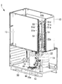
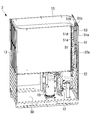
- ⁇ Structure of compressor unit> 2 and 3 show the structure of the compressor unit including the compressor 10 and the outdoor heat exchanger 13 disposed in the outdoor unit 2.
- the compressor 10, the outdoor heat exchanger 13, and the structure relevant to these are shown, and illustration is abbreviate
- the compressor 10 is fixed on the bottom plate 50 in the casing of the outdoor unit 2.
- the compressor 10 has a substantially cylindrical shape having an axis extending in the vertical direction.
- An electric motor (not shown) is accommodated in the lower part of the compressor 10, and a compression mechanism (not shown) such as a scroll part is accommodated in the upper part.
- a leg 10 a is provided at the bottom of the compressor 10, and is fixed to the bottom plate 50 by a stud bolt 49 via an anti-vibration rubber 48.
- the four-way switching valve 12 is located on the lower side of the compressor 10.
- a refrigerant pipe 22 extending upward from the four-way switching valve 12 rises upward along the corner of the outdoor unit 2.
- symbol 19 shown in the figure is an accumulator.
- the refrigerant pipe 22 is connected to the two branch pipes 51 at the branch portion 22a.
- Each branch pipe 51 is provided in parallel starting from the branch portion 22a.
- Each branch pipe 51 includes a rising portion 51a that rises upward, a folded portion 51b that is connected to the rising portion 51a and folds downward in a U-shape, and a falling portion 51c that is connected to the folded portion 51b and falls downward from above. And have.
- a plurality of branch pipes 51d connected to the outdoor heat exchanger 13 are provided in the falling part 51c.
- Each branch pipe 51d is provided at substantially equal intervals in the vertical direction of the falling part 51c.
- the rising portion 51a, the folded portion 51b, and the falling portion 51c are formed by bending the same pipe.
- the rising portion 51a, the folded portion 51b, and the falling portion 51c are provided in an inverted U shape, with the height position of the folded portion 51b being substantially equal to the upper end of the outdoor heat exchanger 13.
- the pipe diameters of the rising part 51a, the folded part 51b, and the falling part 51c are smaller than the pipe diameter of the refrigerant pipe 22.
- the pipe diameter of the branch pipe 51d is smaller than the pipe diameter of the rising part 51a, the folding
- Two outdoor heat exchangers 13 are provided and are bent into an L shape when seen in a plan view. Refrigerant is supplied from the corresponding branch pipes 51 to these two outdoor heat exchangers 13, and the refrigerant is guided to the respective branch pipes 51.
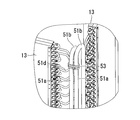
- a fixing portion 53 is provided above the rising portion 51a of the branch pipe 51 to fix the two rising portions 51a together. 4 and 5 show the periphery of the fixing portion 53 in an enlarged manner.
- the fixing portion 53 is made of a heat-insulating material such as foamed polyethylene, for example, and is a band provided so as to wind around the two rising portions 51a.
- the fixed portions 53 prevent the rising portions 51a from being displaced independently.
- the vibration from the compressor 10 is transmitted to the refrigerant pipe 22 and further to the branch pipe 51.
- the branch part 22a branched from the refrigerant pipe 22 to each branch pipe 51 stress is concentrated by vibration.
- a large displacement is caused by vibration above the rising portion 51 a of the branch pipe 51. If the upper part of the rising part 51a is largely displaced, the displacement of the falling part 51c is also increased, and the stress of the branch pipe 51d connected to the outdoor heat exchanger 13 is increased. Therefore, in this embodiment, the rising parts 51a of the branch pipes 51 are fixed to each other by the fixing part 53, so that the branch pipes 51 are integrated and the branch pipes 51 are prevented from vibrating individually. Thereby, the stress concentration in the branch part 22a branched from the refrigerant pipe 22 to each branch pipe 51 and the large displacement above the rising part 51a of the branch pipe 51 can be reduced.
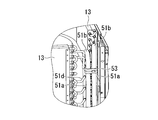
- the fixing portion 53 ′ may be formed of a metal bracket made of a sheet metal. Each rising portion 51a is sandwiched and fixed by a metal bracket. Thereby, fixing
- the compressor 10 is described as being capable of rotating up to 200 rps exceeding 130 rps.
- the present invention is not limited to this, and the compressor rotational speed of 130 rps or less may be used.
- the compressor speed may exceed 200 rps.
- the branch piping 51 was demonstrated as a structure branched into two, this invention is not limited to this, It is good also as a structure branched to three or more. In this case, at least two rising portions 51a located in the vicinity are fixed by the fixing portions 53 and 53 ′.
- a fixing bracket 55 is provided for fixing the upper portion of the rising portion 51 a to the side plate 13 a at the end of the outdoor heat exchanger 13.
- the fixing bracket 55 includes two metal plates bent in a predetermined shape, and the rising portion 51a is sandwiched between these metal plates.
- the rising portion 51 a of the other branch pipe 51 is also fixed to the corresponding side plate 13 a of the outdoor heat exchanger 13 via a fixing bracket 55.
- the vibration of the rising portion 51a can be suppressed by fixing the rising portion 51a to the outdoor heat exchanger 13 through the fixing bracket 55.
- the side plate 13a of the outdoor heat exchanger 13 is made of a relatively strong material such as stainless steel, it is preferable as a target for fixing the fixing bracket 55.
- the fixing bracket 55 may be fixed to the housing that accommodates the outdoor heat exchanger 13, that is, the housing side of the outdoor unit 2, instead of being fixed to the side plate 13 a of the outdoor heat exchanger 13. . Specifically, it may be fixed to the casing or frame of the casing of the outdoor unit 2.
Landscapes
- Engineering & Computer Science (AREA)
- Chemical & Material Sciences (AREA)
- Combustion & Propulsion (AREA)
- Mechanical Engineering (AREA)
- General Engineering & Computer Science (AREA)
- Other Air-Conditioning Systems (AREA)
Abstract
冷媒を圧縮する圧縮機(10)と、圧縮機(10)に接続された冷媒配管(22)と、冷媒配管(22)から並列に分岐された複数の分岐配管(51)と、各分岐配管(51)のそれぞれに接続された複数の室外熱交換器(13)とを備え、各分岐配管(51)は、冷媒配管(22)から分岐して下方から上方へ立ち上がる立上り部(51a)と、立上り部(51a)に接続されて下方へ折り返す折返し部(51b)と、折返し部(51b)に接続されて上方から下方へ立ち下がる立下り部(51c)と、立下り部(51c)と室外熱交換器(13)とを接続する複数の枝管(51d)とを有し、各分岐配管(51)の立上り部(51a)同士を固定する固定部53を備えている。
Description
本発明は、空調機に用いられる圧縮機から発生する振動による配管の応力集中を低減する圧縮機ユニット及びこれを備えた室外機に関するものである。
空調機の室外機には、冷媒を圧縮する圧縮機が設けられている。圧縮機は電動モータによってスクロール部等の圧縮部が駆動され、圧縮冷媒が吐出される。圧縮機と室外熱交換器との間には冷媒配管が接続されている。
冷媒配管と室外熱交換器との間には、複数の分岐配管が設けられることがある(特許文献1参照)。
圧縮機からの振動は、冷媒配管を介して分岐配管へと伝達される。冷媒配管から各分岐配管へと分岐する分岐部では、振動によって応力が集中するおそれがある。特に、本発明者等が検討したところ、例えば130rpsを超えて200rpsまで到達するような高回転数化した圧縮機では、圧縮機からの振動に起因する分岐部での応力集中は無視できないものになることが判明した。
本発明は、このような事情に鑑みてなされたものであって、熱交換器に接続される分岐配管の応力集中を低減することができる圧縮機ユニット及びこれを備えた室外機を提供することを目的とする。
本発明の一態様に係る圧縮機ユニットは、冷媒を圧縮する圧縮機と、該圧縮機に接続された冷媒配管と、該冷媒配管から並列に分岐され、それぞれが熱交換器に接続された複数の分岐配管とを備え、各前記分岐配管は、前記冷媒配管から分岐して下方から上方へ立ち上がる立上り部と、該立上り部に接続されて下方へ折り返す折返し部と、該折返し部に接続されて上方から下方へ立ち下がる立下り部と、該立下り部と前記熱交換器とを接続する複数の枝管とを有し、各前記分岐配管の前記立上り部同士を固定する固定部を備えている。
各熱交換器に接続される分岐配管には、冷媒配管から分岐して下方から上方へ立ち上がる立上り部と、立上り部に接続されて下方へ折り返す折返し部と、折返し部に接続されて上方から下方へと立ち下がる立下り部とが設けられている。これは、熱交換器に貯留された液冷媒が冷媒配管を通り圧縮機に逆流(液バック)しないようにするためである。
圧縮機からの振動は、冷媒配管に伝達され、さらに分岐配管へと伝達される。冷媒配管から各分岐配管へと分岐する分岐部では、振動によって応力が集中する。また、分岐配管の立上り部の上方では振動によって大きく変位する。立上り部の上方が大きく変位すると、立下り部の変位も大きくなり、熱交換器に接続される枝管の応力が大きくなってしまう。
そこで、各分岐配管の立上り部同士を固定部で固定することによって、分岐配管を一体化して各分岐配管が個別に振動することを抑えるようにした。これにより、冷媒配管から各分岐配管へと分岐する分岐部における応力集中や、分岐配管の立上り部の上方における大きな変位を低減することができる。
固定部としては、断熱性を有する材料を用いて立上り配管同士をまとめて巻回して固定する形態や、板金とされた金属ブラケットを用いて立上り部同士を挟み込んで固定する形態等が挙げられる。
また、本発明の一態様に係る圧縮機ユニットは、冷媒を圧縮する圧縮機と、該圧縮機に接続された冷媒配管と、該冷媒配管から並列に分岐され、それぞれが熱交換器に接続された複数の分岐配管とを備え、各前記分岐配管は、前記冷媒配管から分岐して下方から上方へ立ち上がる立上り部と、該立上り部に接続されて下方へ折り返す折返し部と、該折返し部に接続されて上方から下方へ立ち下がる立下り部と、該立下り部と前記熱交換器とを接続する複数の枝管とを有し、前記分岐配管の前記立上り部は、前記熱交換器に対して、または、該熱交換器を収容する筐体側に対して固定されている。
各熱交換器に接続される分岐配管には、冷媒配管から分岐して下方から上方へ立ち上がる立上り部と、立上り部に接続されて下方へ折り返す折返し部と、折返し部に接続されて上方から下方へと立ち下がる立下り部とが設けられている。これは、熱交換器に貯留された液冷媒が冷媒配管を通り圧縮機に逆流(液バック)しないようにするためである。
圧縮機からの振動は、冷媒配管に伝達され、さらに分岐配管へと伝達される。冷媒配管から各分岐配管へと分岐する分岐位置では、振動によって応力が集中する。また、分岐配管の立上り部の上方では振動によって大きく変位する。立上り部の上方が大きく変位すると、立下り部の変位も大きくなり、熱交換器に接続される枝管の応力が大きくなってしまう。
そこで、分岐配管の立上り部を、熱交換器に対して、または、熱交換器を収容する筐体側に固定することによって、各分岐配管が個別に振動することを抑えるようにした。これにより、冷媒配管から各分岐配管へと分岐する分岐位置における応力集中や、分岐配管の立上り部の上方における大きな変位を低減することができる。
また、本発明の一態様に係る室外機は、上記の圧縮機ユニットと、複数の熱交換器と、前記圧縮機ユニット及び各前記熱交換器を収容する筐体とを備えている。
各分岐配管の立上り部同士を固定して一体化することによって、分岐配管の応力集中を低減することができる。
分岐配管の立上り部を、熱交換器に対して、または、熱交換器を収容する筐体側に固定することによって、分岐配管の応力集中を低減することができる。
分岐配管の立上り部を、熱交換器に対して、または、熱交換器を収容する筐体側に固定することによって、分岐配管の応力集中を低減することができる。
以下に、本発明にかかる一実施形態について、図面を参照して説明する。
[第1実施形態]
図1には、1台の室外機に対して複数台の室内機が接続されるマルチ形空調システムの冷媒回路図が示されている。なお、室外機は複数台であっても良い。
[第1実施形態]
図1には、1台の室外機に対して複数台の室内機が接続されるマルチ形空調システムの冷媒回路図が示されている。なお、室外機は複数台であっても良い。
同図に示すように、マルチ形空調システム1は、1台の室外機2に、複数台の室内機3A,3Bが並列に接続されたものである。複数台の室内機3A,3Bは、室外機2に接続されているガス側配管4と液側配管5との間に分岐器6を介して互いに並列に接続されている。
室外機2は、冷媒を圧縮するインバータ駆動の圧縮機10と、冷媒の循環方向を切換える四方切換弁12と、冷媒と外気とを熱交換させる室外熱交換器13と、室外熱交換器13と一体的に構成されている過冷却コイル14と、室外膨張弁(EEVH)15と、液冷媒を貯留するレシーバ16と、液冷媒に過冷却を与える過冷却熱交換器17と、過冷却熱交換器17に分流される冷媒量を制御する過冷却用膨張弁(EEVSC)18と、圧縮機10に吸入される冷媒ガスから液分を分離し、ガス分のみを圧縮機10側に吸入させるアキュームレータ19と、ガス側操作弁20と、液側操作弁21とを備えている。
圧縮機10は、130rpsを超えて200rpsまで回転可能となっている。圧縮機10の吐出側には、吐出配管25を介してオイルセパレータ26が接続されている。オイルセパレータ26では、圧縮冷媒中のミスト状の潤滑油(オイル)が冷媒から分離される。オイルセパレータ26でミスト状潤滑油が分離された冷媒は、四方切換弁12へと導かれる。オイルセパレータ26で分離されオイルセパレータ26内に貯留された潤滑油は、油戻し配管27を介して圧縮機10の低圧側に戻される。
油戻し配管27には、電磁弁28とキャピラリ部29が設けられている。電磁弁28は、図示しない制御部によって弁の開閉が制御され、油戻し配管27内を流れる油量が調整される。キャピラリ部29は、固定絞りとして用いられ、通過する潤滑油の圧力を減少させる。
室外機2側の上記各機器は、冷媒配管22を介して順次接続され、公知の室外側冷媒回路23を構成している。また、室外機2には、室外熱交換器13に対して外気を送風する室外ファン24が設けられている。
ガス側配管4及び液側配管5は、室外機2のガス側操作弁20及び液側操作弁21に接続される冷媒配管であり、現場での据え付け施工時に、室外機2とそれに接続される複数台の室内機3A,3Bとの間の距離に応じて、その配管長が適宜設定されるようになっている。ガス側配管4及び液側配管5の途中には、複数の分岐器6が設けられ、該分岐器6を介して適宜台数の室内機3A,3Bが接続されている。これによって、密閉された1系統の冷凍サイクル(冷媒回路)7が構成されている。
室内機3A,3Bは、室内空気を冷媒と熱交換させて冷却又は加熱し、室内の空調に供する室内熱交換器30と、室内膨張弁(EEVC)31と、室内熱交換器30を介して室内空気を循環させる室内ファン32と、室内コントローラ33とを備えており、室内側の分岐ガス側配管4A,4B及び分岐液側配管5A,5Bを介して分岐器6に接続されている。
上記のマルチ形空調システム1において、冷房運転は、以下のように行われる。
圧縮機10で圧縮され、吐出された高温高圧の冷媒ガスは、四方切換弁12により室外熱交換器13側に循環され、室外熱交換器13で室外ファン24により送風される外気と熱交換されて凝縮液化される。この液冷媒は、過冷却コイル14で更に冷却された後、室外膨張弁15を通過し、レシーバ16内にいったん貯留される。
圧縮機10で圧縮され、吐出された高温高圧の冷媒ガスは、四方切換弁12により室外熱交換器13側に循環され、室外熱交換器13で室外ファン24により送風される外気と熱交換されて凝縮液化される。この液冷媒は、過冷却コイル14で更に冷却された後、室外膨張弁15を通過し、レシーバ16内にいったん貯留される。
レシーバ16で循環量が調整された液冷媒は、過冷却熱交換器17を経て液冷媒配管側を流通される過程で、液冷媒配管から一部分流され、過冷却用膨張弁18で断熱膨張された冷媒と熱交換されて過冷却度が付与される。この液冷媒は、液側操作弁21を経て室外機2から液側配管5へと導かれ、分岐器6を介して各室内機3A,3Bの分岐液側配管5A,5Bへと分流される。
分岐液側配管5A,5Bに分流された液冷媒は、各室内機3A,3Bに流入し、室内膨張弁31で断熱膨張され、気液二相流となって室内熱交換器30に流入される。室内熱交換器30では、室内ファン32により循環される室内空気と冷媒とが熱交換され、室内空気は冷却されて室内の冷房に供される。一方、冷媒はガス化され、分岐ガス側配管4A,4Bを経て分岐器6に至り、他の室内機からの冷媒ガスとガス側配管4で合流される。
ガス側配管4で合流された冷媒ガスは、再び室外機2に戻り、ガス側操作弁20、四方切換弁12を経て、過冷却熱交換器17からの冷媒ガスと合流された後、アキュームレータ19に導入される。アキュームレータ19では、冷媒ガス中に含まれている液分が分離され、ガス分のみが圧縮機10に吸入される。この冷媒は、圧縮機10において再び圧縮され、以上のサイクルを繰り返すことによって冷房運転が行われる。
一方、暖房運転は、以下のように行われる。
圧縮機10により圧縮され、吐出された高温高圧の冷媒ガスは、四方切換弁12を介してガス側操作弁20側に循環される。この高圧ガス冷媒は、ガス側操作弁20、ガス側配管4を経て室外機2から導出され、分岐器6、室内側の分岐ガス側配管4A,4Bを経て複数台の室内機3A,3Bに導入される。
圧縮機10により圧縮され、吐出された高温高圧の冷媒ガスは、四方切換弁12を介してガス側操作弁20側に循環される。この高圧ガス冷媒は、ガス側操作弁20、ガス側配管4を経て室外機2から導出され、分岐器6、室内側の分岐ガス側配管4A,4Bを経て複数台の室内機3A,3Bに導入される。
室内機3A,3Bに導入された高温高圧の冷媒ガスは、室内熱交換器30で室内ファン32を介して循環される室内空気と熱交換され、これにより加熱された室内空気は室内に吹出されて暖房に供される。一方、室内熱交換器30で凝縮液化された冷媒は、室内膨張弁31、分岐液側配管5A,5Bを経て分岐器6に至り、他の室内機からの冷媒と合流され、液側配管5を経て室外機2に戻る。なお、暖房時、室内機3A,3Bでは、凝縮器として機能する室内熱交換器30の冷媒出口温度又は冷媒過冷却度が制御目標値となるように、室内膨張弁31の開度が室内コントローラ33を介して制御される。
室外機2に戻った冷媒は、液側操作弁21を経て過冷却熱交換器17に至り、冷房時の場合と同様に過冷却が付与された後、レシーバ16に流入され、いったん貯留されることにより循環量が調整される。この液冷媒は、室外膨張弁15に供給されて断熱膨張された後、過冷却コイル14を経て室外熱交換器13に流入される。
室外熱交換器13では、室外ファン24から送風される外気と冷媒とが熱交換され、冷媒は外気から吸熱して蒸発ガス化される。この冷媒は、室外熱交換器13から四方切換弁12を経て、過冷却熱交換器17からの冷媒ガスと合流された後、アキュームレータ19に導入される。アキュームレータ19では、冷媒ガス中に含まれている液分が分離されてガス分のみが圧縮機10に吸入され、圧縮機10において再び圧縮される。以上のサイクルを繰り返すことによって暖房運転が行われる。
<圧縮機ユニットの構造>
図2及び図3には、室外機2内に配置された圧縮機10や室外熱交換器13等を備えた圧縮機ユニットの構造が示されている。同図では、圧縮機10と、室外熱交換器13と、これらに関連する構造が示されており、他の機器については図示が省略されている。
図2及び図3には、室外機2内に配置された圧縮機10や室外熱交換器13等を備えた圧縮機ユニットの構造が示されている。同図では、圧縮機10と、室外熱交換器13と、これらに関連する構造が示されており、他の機器については図示が省略されている。
圧縮機10は、室外機2の筐体内で、底板50上に固定されている。圧縮機10は、鉛直方向に延在する軸線を有する略円筒形状とされている。圧縮機10の下部には電動モータ(図示せず)が収容され、上部にはスクロール部等の圧縮機構(図示せず)が収納されている。圧縮機10の底部には脚部10aが設けられ、防振ゴム48を介してスタッドボルト49によって底板50に対して固定されている。
圧縮機10の下部側方には、四方切換弁12が位置している。四方切換弁12から上方に延びる冷媒配管22は室外機2の角部に沿って上方に立ち上がっている。なお、同図中に示された符号19は、アキュームレータである。
冷媒配管22は、分岐部22aにおいて2本の分岐配管51に接続されている。各分岐配管51は、分岐部22aを起点として並列に設けられている。各分岐配管51は、上方へ立ち上がる立上り部51aと、立上り部51aに接続されて下方へU字状に折り返す折返し部51bと、折返し部51bに接続されて上方から下方へ立ち下がる立下り部51cとを有している。立下り部51cには、室外熱交換器13に接続される複数の枝管51dが設けられている。各枝管51dは、立下り部51cの上下方向に略等間隔で設けられている。
立上り部51a、折返し部51b及び立下り部51cは、同一配管を折り曲げて形成された形状となっている。立上り部51a、折返し部51b及び立下り部51cは、折返し部51bの高さ位置が室外熱交換器13の上端と略同等の位置とされた上で、逆U字形状に設けられている。これにより、暖房運転時に蒸発器として使用される室外熱交換器13に貯留された液冷媒が冷媒配管22を通り圧縮機10に逆流(液バック)しないようになっている。
冷媒配管22の配管径よりも、立上り部51a、折返し部51b及び立下り部51cの配管径の方が小さい。そして、立上り部51a、折返し部51b及び立下り部51cの配管径よりも、枝管51dの配管径の方が小さい。
室外熱交換器13は、2つ設けられており、平面視した場合にL字に折り曲げられた形状となっている。これら2つの室外熱交換器13に対して、対応するそれぞれの分岐配管51から冷媒が供給され、また、各分岐配管51に冷媒が導かれるようになっている。
分岐配管51の立上り部51aの上方には、2つの立上り部51aをまとめて一体的に固定する固定部53が設けられている。図4及び図5には、固定部53の周りが拡大されて示されている。
固定部53は、例えば発泡ポリエチレン等の断熱性を有する材料で構成されており、2つの立上り部51aの周囲を巻回するように設けられたバンドとなっている。固定部53によって、互いの立上り部51aが独立して変位しないようになっている。
本実施形態によれば、以下の作用効果を奏する。
圧縮機10からの振動は、冷媒配管22に伝達され、さらに分岐配管51へと伝達される。冷媒配管22から各分岐配管51へと分岐する分岐部22aでは、振動によって応力が集中する。また、分岐配管51の立上り部51aの上方では振動によって大きく変位する。立上り部51aの上方が大きく変位すると、立下り51cの変位も大きくなり、室外熱交換器13に接続される枝管51dの応力が大きくなってしまう。
そこで、本実施形態では、各分岐配管51の立上り部51a同士を固定部53で固定することによって、分岐配管51を一体化して各分岐配管51が個別に振動することを抑えるようにした。これにより、冷媒配管22から各分岐配管51へと分岐する分岐部22aにおける応力集中や、分岐配管51の立上り部51aの上方における大きな変位を低減することができる。
本実施形態は、図6及び図7のように変形することができる。
図6及び図7に示されているように、固定部53’を板金とされた金属ブラケットで構成することとしても良い。金属ブラケットで各立上り部51aを挟み込んで固定する。これにより、安価に固定部53’を構成することができる。
図6及び図7に示されているように、固定部53’を板金とされた金属ブラケットで構成することとしても良い。金属ブラケットで各立上り部51aを挟み込んで固定する。これにより、安価に固定部53’を構成することができる。
なお、上述した実施形態では、130rpsを超えて200rpsまで回転可能な圧縮機10として説明したが、本発明はこれに限定されるものではなく、130rps以下の圧縮機回転数であってもよく、また200rpsを超える圧縮機回転数であっても良い。
また、分岐配管51が2本に分岐する構成として説明したが、本発明はこれに限定されるものではなく、3本以上に分岐する構成としても良い。この場合には、近くに位置する少なくとも2つの立上り部51a同士を固定部53,53’で固定する。
また、分岐配管51が2本に分岐する構成として説明したが、本発明はこれに限定されるものではなく、3本以上に分岐する構成としても良い。この場合には、近くに位置する少なくとも2つの立上り部51a同士を固定部53,53’で固定する。
[第2実施形態]
以下に、本発明の第2実施形態について説明する。本実施形態は、第1実施形態に対して、立上り部51aを固定する構成が異なる。したがって、以下では、第1実施形態に対する相違点のみについて説明し、共通する構成については同一符号を付しその説明を省略する。
以下に、本発明の第2実施形態について説明する。本実施形態は、第1実施形態に対して、立上り部51aを固定する構成が異なる。したがって、以下では、第1実施形態に対する相違点のみについて説明し、共通する構成については同一符号を付しその説明を省略する。
図8に示されているように、立上り部51aの上方を室外熱交換器13の端部の側板13aに固定する固定用ブラケット55が設けられている。固定用ブラケット55は、所定形状に屈曲された2つの金属プレートを備え、これら金属プレートの間に立上り部51aを挟み込むようになっている。他方の分岐配管51の立上り部51aについても、図8では示していないが、対応する室外熱交換器13の側板13aに対して固定用ブラケット55を介して固定されている。
固定用ブラケット55を介して、立上り部51aを室外熱交換器13に対して固定することで、立上り部51aの振動を抑えることができる。また、室外熱交換器13の側板13aはステンレス等の比較的強度のある材料で構成されているため、固定用ブラケット55を固定する対象として好ましい。
なお、分岐配管51が2本に分岐する構成として説明したが、本発明はこれに限定されるものではなく、3本以上に分岐する構成としても良い。
また、固定用ブラケット55は、室外熱交換器13の側板13aに固定することに代えて、室外熱交換器13を収容する筐体、すなわち室外機2の筐体側に固定するようにしても良い。具体的には、室外機2の筐体のケーシングやフレームに対して固定しても良い。
また、固定用ブラケット55は、室外熱交換器13の側板13aに固定することに代えて、室外熱交換器13を収容する筐体、すなわち室外機2の筐体側に固定するようにしても良い。具体的には、室外機2の筐体のケーシングやフレームに対して固定しても良い。
1 マルチ形空調システム
2 室外機
3A,3B 室内機
10 圧縮機
10a 脚部
13 室外熱交換器
19 アキュームレータ
22 冷媒配管
22a 分岐部
25 吐出配管
48 防振ゴム
49 スタッドボルト
50 底板
51 分岐配管
51a 立上り部
51b 折返し部
51c 立下り部
51d 枝管
53,53’ 固定部
55 固定用ブラケット
2 室外機
3A,3B 室内機
10 圧縮機
10a 脚部
13 室外熱交換器
19 アキュームレータ
22 冷媒配管
22a 分岐部
25 吐出配管
48 防振ゴム
49 スタッドボルト
50 底板
51 分岐配管
51a 立上り部
51b 折返し部
51c 立下り部
51d 枝管
53,53’ 固定部
55 固定用ブラケット
Claims (3)
- 冷媒を圧縮する圧縮機と、
該圧縮機に接続された冷媒配管と、
該冷媒配管から並列に分岐され、それぞれが熱交換器に接続された複数の分岐配管と、
を備え、
各前記分岐配管は、前記冷媒配管から分岐して下方から上方へ立ち上がる立上り部と、該立上り部に接続されて下方へ折り返す折返し部と、該折返し部に接続されて上方から下方へ立ち下がる立下り部と、該立下り部と前記熱交換器とを接続する複数の枝管とを有し、
各前記分岐配管の前記立上り部同士を固定する固定部を備えている圧縮機ユニット。 - 冷媒を圧縮する圧縮機と、
該圧縮機に接続された冷媒配管と、
該冷媒配管から並列に分岐され、それぞれが熱交換器に接続された複数の分岐配管と、
を備え、
各前記分岐配管は、前記冷媒配管から分岐して下方から上方へ立ち上がる立上り部と、該立上り部に接続されて下方へ折り返す折返し部と、該折返し部に接続されて上方から下方へ立ち下がる立下り部と、該立下り部と前記熱交換器とを接続する複数の枝管とを有し、
前記分岐配管の前記立上り部は、前記熱交換器に対して、または、該熱交換器を収容する筐体側に対して固定されている圧縮機ユニット。 - 請求項1又は2に記載の圧縮機ユニットと、
複数の熱交換器と、
前記圧縮機ユニット及び各前記熱交換器を収容する筐体と、
を備えている室外機。
Priority Applications (1)
| Application Number | Priority Date | Filing Date | Title |
|---|---|---|---|
| EP17879851.8A EP3502576A4 (en) | 2016-12-13 | 2017-10-25 | COMPRESSOR UNIT AND OUTDOOR UNIT THEREWITH |
Applications Claiming Priority (2)
| Application Number | Priority Date | Filing Date | Title |
|---|---|---|---|
| JP2016-241051 | 2016-12-13 | ||
| JP2016241051A JP2018096609A (ja) | 2016-12-13 | 2016-12-13 | 圧縮機ユニット及びこれを備えた室外機 |
Publications (1)
| Publication Number | Publication Date |
|---|---|
| WO2018110103A1 true WO2018110103A1 (ja) | 2018-06-21 |
Family
ID=62559650
Family Applications (1)
| Application Number | Title | Priority Date | Filing Date |
|---|---|---|---|
| PCT/JP2017/038586 WO2018110103A1 (ja) | 2016-12-13 | 2017-10-25 | 圧縮機ユニット及びこれを備えた室外機 |
Country Status (3)
| Country | Link |
|---|---|
| EP (1) | EP3502576A4 (ja) |
| JP (1) | JP2018096609A (ja) |
| WO (1) | WO2018110103A1 (ja) |
Cited By (1)
| Publication number | Priority date | Publication date | Assignee | Title |
|---|---|---|---|---|
| CN112424533A (zh) * | 2018-06-29 | 2021-02-26 | 大金工业株式会社 | 室外空调装置 |
Families Citing this family (3)
| Publication number | Priority date | Publication date | Assignee | Title |
|---|---|---|---|---|
| CN108954562B (zh) * | 2018-07-25 | 2021-02-23 | 广东美的暖通设备有限公司 | 空调器室外机及具有其的空调器 |
| JP6863395B2 (ja) * | 2019-02-18 | 2021-04-21 | ダイキン工業株式会社 | 空気調和装置 |
| JP7399653B2 (ja) * | 2019-09-11 | 2023-12-18 | 東芝キヤリア株式会社 | 熱源装置 |
Citations (3)
| Publication number | Priority date | Publication date | Assignee | Title |
|---|---|---|---|---|
| JP2004324982A (ja) * | 2003-04-24 | 2004-11-18 | Matsushita Electric Ind Co Ltd | 空気調和機 |
| JP2009275990A (ja) * | 2008-05-15 | 2009-11-26 | Daikin Ind Ltd | 分岐配管の応力低減金具およびその使用方法、ならびに分岐配管組立体 |
| JP2015087073A (ja) * | 2013-10-31 | 2015-05-07 | ダイキン工業株式会社 | 熱交換器および空気調和装置 |
Family Cites Families (4)
| Publication number | Priority date | Publication date | Assignee | Title |
|---|---|---|---|---|
| JP4982401B2 (ja) * | 2008-02-06 | 2012-07-25 | 日立アプライアンス株式会社 | 空気調和機の室外機 |
| JP2011158109A (ja) * | 2010-01-29 | 2011-08-18 | Sanyo Electric Co Ltd | 冷凍機の室外ユニット |
| KR20120078889A (ko) * | 2011-01-03 | 2012-07-11 | 엘지전자 주식회사 | 공기조화기의 실외기 |
| CN204853733U (zh) * | 2015-06-19 | 2015-12-09 | 阿尔西制冷工程技术(北京)有限公司 | 空调机组 |
-
2016
- 2016-12-13 JP JP2016241051A patent/JP2018096609A/ja active Pending
-
2017
- 2017-10-25 EP EP17879851.8A patent/EP3502576A4/en not_active Withdrawn
- 2017-10-25 WO PCT/JP2017/038586 patent/WO2018110103A1/ja unknown
Patent Citations (3)
| Publication number | Priority date | Publication date | Assignee | Title |
|---|---|---|---|---|
| JP2004324982A (ja) * | 2003-04-24 | 2004-11-18 | Matsushita Electric Ind Co Ltd | 空気調和機 |
| JP2009275990A (ja) * | 2008-05-15 | 2009-11-26 | Daikin Ind Ltd | 分岐配管の応力低減金具およびその使用方法、ならびに分岐配管組立体 |
| JP2015087073A (ja) * | 2013-10-31 | 2015-05-07 | ダイキン工業株式会社 | 熱交換器および空気調和装置 |
Non-Patent Citations (1)
| Title |
|---|
| See also references of EP3502576A4 * |
Cited By (1)
| Publication number | Priority date | Publication date | Assignee | Title |
|---|---|---|---|---|
| CN112424533A (zh) * | 2018-06-29 | 2021-02-26 | 大金工业株式会社 | 室外空调装置 |
Also Published As
| Publication number | Publication date |
|---|---|
| JP2018096609A (ja) | 2018-06-21 |
| EP3502576A1 (en) | 2019-06-26 |
| EP3502576A4 (en) | 2019-09-25 |
Similar Documents
| Publication | Publication Date | Title |
|---|---|---|
| WO2018110103A1 (ja) | 圧縮機ユニット及びこれを備えた室外機 | |
| WO2009119134A1 (ja) | マルチ形空気調和機の油戻し運転方法およびマルチ形空気調和機 | |
| CN104011471B (zh) | 空调装置 | |
| WO2018110331A1 (ja) | 圧縮機ユニット及びこれを備えた室外機 | |
| WO2007102463A1 (ja) | 冷凍装置 | |
| EP2835589B1 (en) | Air conditioner | |
| JP4118254B2 (ja) | 冷凍装置 | |
| JP5403039B2 (ja) | 空気調和装置 | |
| US11274863B2 (en) | Air conditioning system | |
| AU2016213420A1 (en) | Air conditioning apparatus | |
| WO2018116613A1 (ja) | 圧縮機ユニット及びこれを備えた室外機 | |
| JP6242289B2 (ja) | 冷凍サイクル装置 | |
| EP3505834A1 (en) | Compressor unit, and outdoor unit with same | |
| JP2007093167A (ja) | 空気調和機用液ガス熱交換器 | |
| JP4916342B2 (ja) | 冷凍装置 | |
| JP2010019533A (ja) | 空気調和装置の室外機 | |
| CN114278999B (zh) | 空调器 | |
| WO2021149222A1 (ja) | 冷凍サイクル装置の室外機 | |
| WO2018110330A1 (ja) | 圧縮機ユニット及びこれを備えた室外機 | |
| WO2024177143A1 (ja) | 冷凍サイクル装置 | |
| JP2018096582A (ja) | 冷凍装置 | |
| JP5192882B2 (ja) | 空気調和機 | |
| KR20050074111A (ko) | 공기조화기용 어큐뮬레이터 | |
| JP2021196024A (ja) | 接続配管 | |
| JP2015055381A (ja) | 冷凍装置 |
Legal Events
| Date | Code | Title | Description |
|---|---|---|---|
| 121 | Ep: the epo has been informed by wipo that ep was designated in this application |
Ref document number: 17879851 Country of ref document: EP Kind code of ref document: A1 |
|
| ENP | Entry into the national phase |
Ref document number: 2017879851 Country of ref document: EP Effective date: 20190320 |
|
| NENP | Non-entry into the national phase |
Ref country code: DE |