WO2018100904A1 - シート製造装置、シート製造方法、パルプ由来製品製造装置およびパルプ由来製品製造方法 - Google Patents
シート製造装置、シート製造方法、パルプ由来製品製造装置およびパルプ由来製品製造方法 Download PDFInfo
- Publication number
- WO2018100904A1 WO2018100904A1 PCT/JP2017/037499 JP2017037499W WO2018100904A1 WO 2018100904 A1 WO2018100904 A1 WO 2018100904A1 JP 2017037499 W JP2017037499 W JP 2017037499W WO 2018100904 A1 WO2018100904 A1 WO 2018100904A1
- Authority
- WO
- WIPO (PCT)
- Prior art keywords
- unit
- raw material
- sterilization
- sheet
- cutting
- Prior art date
- Legal status (The legal status is an assumption and is not a legal conclusion. Google has not performed a legal analysis and makes no representation as to the accuracy of the status listed.)
- Ceased
Links
Images




Classifications
-
- B—PERFORMING OPERATIONS; TRANSPORTING
- B27—WORKING OR PRESERVING WOOD OR SIMILAR MATERIAL; NAILING OR STAPLING MACHINES IN GENERAL
- B27N—MANUFACTURE BY DRY PROCESSES OF ARTICLES, WITH OR WITHOUT ORGANIC BINDING AGENTS, MADE FROM PARTICLES OR FIBRES CONSISTING OF WOOD OR OTHER LIGNOCELLULOSIC OR LIKE ORGANIC MATERIAL
- B27N3/00—Manufacture of substantially flat articles, e.g. boards, from particles or fibres
- B27N3/04—Manufacture of substantially flat articles, e.g. boards, from particles or fibres from fibres
-
- D—TEXTILES; PAPER
- D04—BRAIDING; LACE-MAKING; KNITTING; TRIMMINGS; NON-WOVEN FABRICS
- D04H—MAKING TEXTILE FABRICS, e.g. FROM FIBRES OR FILAMENTARY MATERIAL; FABRICS MADE BY SUCH PROCESSES OR APPARATUS, e.g. FELTS, NON-WOVEN FABRICS; COTTON-WOOL; WADDING ; NON-WOVEN FABRICS FROM STAPLE FIBRES, FILAMENTS OR YARNS, BONDED WITH AT LEAST ONE WEB-LIKE MATERIAL DURING THEIR CONSOLIDATION
- D04H1/00—Non-woven fabrics formed wholly or mainly of staple fibres or like relatively short fibres
- D04H1/70—Non-woven fabrics formed wholly or mainly of staple fibres or like relatively short fibres characterised by the method of forming fleeces or layers, e.g. reorientation of fibres
- D04H1/72—Non-woven fabrics formed wholly or mainly of staple fibres or like relatively short fibres characterised by the method of forming fleeces or layers, e.g. reorientation of fibres the fibres being randomly arranged
- D04H1/732—Non-woven fabrics formed wholly or mainly of staple fibres or like relatively short fibres characterised by the method of forming fleeces or layers, e.g. reorientation of fibres the fibres being randomly arranged by fluid current, e.g. air-lay
Definitions
- the present invention relates to a sheet manufacturing apparatus, a sheet manufacturing method, a pulp-derived product manufacturing apparatus, and a pulp-derived product manufacturing method.
- Paper recycling has become widespread from the viewpoint of resource utilization, but in the past, accumulated waste paper has been industrially produced as recycled paper, and its method is called so-called wet processing. Regenerated pulp produced by disaggregation with water was formed on recycled paper (Patent Document 1).
- waste paper is discharged after being used in various ways, and it is not easy to sort the state of breakage or contamination.
- waste paper contaminated with bacteria cannot be visually judged and eliminated, and it must be avoided to supply the consumer with bacteria attached to recycled paper regenerated from the waste paper.
- Patent Document 1 generates a sterilized recycled pulp by adding an antibacterial agent, a sterilizing agent, a bactericidal agent, etc. as one of additives to the waste paper disaggregation water stored in the pulp adjusting unit, It is disclosed to suppress the remaining of contaminants such as bacteria on recycled paper.
- Patent Documents 2 to 4 There is a dry recycled paper manufacturing device that does not use water as a technology for forming recycled paper in the office and forming paper that has been printed and discarded in the office in recent years into recycled paper and putting it into the printing machine as printing paper.
- Patent Documents 2 to 4 which disclose dry paper manufacturing apparatuses using dry processes, do not disclose sterilization means as disclosed in Patent Document 1.
- the sterilization means using a large amount of water as disclosed in Patent Document 1 cannot be applied as it is.
- a conventional dry-type recycled paper manufacturing apparatus can be said to be a technology applied to a premise that uses used paper as a material, which is maintained in a relatively hygienic state, such as paper used in an office environment. Then, it aims at obtaining the sheet manufacturing apparatus and manufacturing method which make it possible to raise the freedom degree of the material to procure.
- the present invention has been made to solve at least a part of the problems described above, and can be realized as the following forms or application examples.
- a raw material supply unit that supplies a raw material, a defibrating unit that defibrates the raw material to form raw material fibers, and a deposit on which the raw material fibers are deposited
- a pressurizing unit that pressurizes the raw material, wherein the raw material supply unit includes a cutting unit that cuts the raw material, and includes a sterilization unit that sterilizes the raw material before being supplied to the cutting unit.
- the sheet manufacturing apparatus includes a used paper as a raw material, that is, a defibrating unit that defibrates waste paper and forms raw material fibers, and a pressurizing unit that pressurizes a deposit in which raw material fibers are deposited in the thickness direction And a so-called dry-type recycled paper manufacturing apparatus.
- Waste paper used as a raw material is used and discharged in various usage environments, and it can be said that it is extremely difficult to obtain waste paper sorted according to the level of bacterial contamination.
- the sheet manufacturing apparatus of this application example even when used paper as a raw material is obtained from a wide range of suppliers, it can be sterilized in the state of used paper in the sterilization section before defibrating the used paper. That is, it is possible to obtain used paper that is a raw material that is not limited to a supplier. And since the sheet
- the raw material is a sheet-like material, and includes a transport unit that transports the raw material to the cutting unit in a single sheet, and the sterilization unit is transported through the transport unit. It is arranged so that sterilization can be performed on the raw material sheet.
- the raw material is a sheet-like material, which is conveyed one by one, that is, one by one to the sterilization unit, and can be sterilized to prevent unsterilized raw material from being fed into the cutting unit. To do.
- the sterilization unit includes a light irradiation unit that irradiates a sterilization line.
- the raw material can be easily sterilized by irradiating the raw material with a sterilization line which is a light beam having a wavelength range having a sterilizing power.
- a sterilization line which is a light beam having a wavelength range having a sterilizing power.
- a light beam having a wavelength of around 260 nm so-called ultraviolet rays can be used.
- the sterilization unit includes a liquid discharge unit that discharges a bactericide solution.
- the liquid bactericidal chemical solution can penetrate into the raw material, and a high bactericidal effect can be obtained.
- the sterilization unit includes a water vapor injection unit that injects water vapor heated to a sterilizable temperature.
- Boil sterilization known as a conventional sterilization method is a method of sterilizing by immersing in boiling water, so-called boiling water of 100 ° C. According to the application example described above, since steam can be heated to a temperature equal to or higher than the boiling point of water, the raw material can be sterilized using readily available water. Moreover, sterilization can be performed to the inside of a raw material by water vapor
- the sterilization unit includes a humidification unit that humidifies the raw material and a microwave irradiation unit that irradiates microwaves.
- moisture can be preliminarily contained in the raw material, and the raw material can be heated by microwave heating of water molecules by microwaves. So-called heat sterilization can be easily performed.
- moisture content contained in the raw material can permeate
- the sheet manufacturing method of this application example includes a raw material supply step for supplying raw materials, a sterilization step for sterilizing the raw materials, a cutting step for cutting the sterilized raw materials, and the cut raw materials.
- the method includes a defibrating step for defibrating, a deposition step for depositing the raw material fibers formed by the defibrating step, and a pressurizing step for pressurizing the deposit in the thickness direction.
- the sheet manufacturing method of this application example includes a used paper as a raw material, that is, a defibrating step for defibrating waste paper to form raw material fibers, a deposition step for depositing raw material fibers, and a deposit obtained by depositing raw material fibers. And a pressurizing step of pressurizing in the thickness direction, so-called dry-type recycled paper manufacturing method. Waste paper used as a raw material is used and discharged in various usage environments, and it can be said that it is extremely difficult to obtain waste paper sorted according to the level of bacterial contamination.
- the sheet manufacturing method of this application example even if the used paper as a raw material is obtained from a wide range of suppliers, the raw material sterilized in the state of the used paper in the sterilization process is input to the defibrating process of the used paper Can do. That is, it is possible to obtain used paper that is a raw material that is not limited to a supplier. And since the sheet
- the raw material is a sheet-like material
- the cutting process is performed after the sterilization process is performed on the raw material of a single wafer.
- the raw material is a sheet-like material, and a sterilization process can be performed one sheet at a time, that is, a sterilization process can be performed, and an unsterilized raw material can be prevented from being transferred to a cutting process. To do.
- the sterilization step includes a sterilization line irradiation step of irradiating the raw material with a sterilization line.
- the raw material can be easily sterilized by irradiating the raw material with a sterilization line which is a light beam having a wavelength range having a sterilizing power.
- a sterilization line which is a light beam having a wavelength range having a sterilizing power.
- a light beam having a wavelength of around 260 nm so-called ultraviolet rays can be used.
- the sterilizing step includes a sterilizing agent applying step of applying a sterilizing agent to the raw material.
- the applied bactericide penetrates into the raw material, and a high bactericidal effect can be obtained.
- the sterilization step includes a water vapor injection step of injecting water vapor heated to a temperature at which the raw material can be sterilized.
- the boil sterilization known in the conventional sterilization method is a method of sterilizing by immersing in boiling water, so-called boiling water of 100 ° C.
- the raw material can be sterilized using readily available water. Further, sterilization can be performed by spraying water vapor through the raw material.
- the sterilization step includes a humidification step of humidifying the raw material and a microwave irradiation step of irradiating microwaves.
- moisture can be preliminarily contained in the raw material by the humidification step, and the raw material can be heated by microwave heating of the water molecules by the microwave in the microwave irradiation step. So-called heat sterilization can be easily performed.
- moisture content contained in the raw material can permeate
- the pulp-derived product manufacturing apparatus of this application example includes a raw material supply unit that supplies a raw material, and a defibrating unit that defibrates the raw material to form raw material fibers, A cutting unit that cuts the raw material; and a transport unit that transports the raw material to the cutting unit, wherein the raw material is a sheet-like material, and the transport unit feeds the raw material to the cutting unit in a single sheet.
- a sterilization unit that conveys and sterilizes the raw material before supply to the cutting unit is provided, and the sterilization unit is disposed so that sterilization processing can be performed on a single sheet of the raw material conveyed through the conveyance unit. It is characterized by that.
- the pulp-derived product manufacturing apparatus of this application example is an apparatus for manufacturing a so-called dry-type recycled pulp having a defibrating unit for defibrating used paper as a raw material, that is, used paper to form raw material fibers.
- Waste paper used as a raw material is used and discharged in various usage environments, and it can be said that it is extremely difficult to obtain waste paper sorted according to the level of bacterial contamination.
- Pulp-derived products refer to products manufactured using cellulose fiber pulp produced from plants such as wood as one of the raw materials.
- the pulp-derived product manufacturing apparatus of this application example is an apparatus that manufactures pulp supplied as one of product raw materials from sheet-shaped raw materials.
- the pulp-derived product manufacturing apparatus of this application example even when used paper as a raw material is obtained from a wide range of suppliers, it can be sterilized in the state of used paper in the sterilization section before defibrating the used paper. . That is, it is possible to obtain used paper that is a raw material that is not limited to a supplier.
- the raw material is a sheet-like material, and it can be conveyed one by one, that is, one by one to the sterilization unit, and sterilization can be performed, so that unsterilized raw material can be prevented from being put into the cutting unit. Therefore, since the pulp regenerated from waste paper is obtained in a sterilized state, the risk of bacterial infection to the user can be reduced.
- a regenerated pulp having improved safety as compared with the prior art.
- it can be suitably used for products that require strong hygiene management, such as sanitary products such as disposable diapers and water-absorbing pads, and sanitary products.
- the pulp-derived product manufacturing method of this application example includes a raw material supply step for supplying raw materials, a sterilization step for sterilizing the raw materials, a cutting step for cutting the sterilized raw materials, and the cut A defibrating step of defibrating the raw material, wherein the raw material is a sheet-like material, and the cutting step is performed after the sterilizing step is performed on the raw material of a sheet To do.
- the sterilization process is performed before the used paper defibrating process, and the sterilized waste paper is input can do. That is, it is possible to obtain used paper that is a raw material that is not limited to a supplier.
- the raw material is a sheet-like material, and it can be conveyed one by one, that is, one by one to the sterilization process, so that sterilization can be performed and the unsterilized raw material can be prevented from being transferred to the cutting process. Therefore, since the pulp regenerated from waste paper is obtained in a sterilized state, the risk of bacterial infection to the user can be reduced.
- a regenerated pulp having improved safety as compared with the prior art.
- it can be suitably used for products that require strong hygiene management, such as sanitary products such as disposable diapers and water-absorbing pads, and sanitary products.
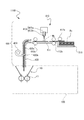
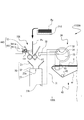
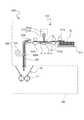
- the lineblock diagram showing the schematic structure of the sheet manufacturing device concerning a 1st embodiment The block diagram which shows schematic structure of the sheet manufacturing apparatus which concerns on 2nd Embodiment.
- FIG. 1 is a configuration diagram showing a schematic configuration of a sheet manufacturing apparatus according to the first embodiment.
- a sheet manufacturing apparatus 1000 shown in FIG. 1 includes a manufacturing unit 100 that forms used paper Pu as a raw material on recycled paper Pr, a control unit 110, and a raw material supply unit 200 that supplies used paper Pu as a raw material.
- the manufacturing unit 100 includes a crushing unit 10 as a cutting unit, a defibrating unit 20, a sorting unit 30, a first web forming unit 40, a rotating body 45, a mixing unit 50, a deposition unit 60, a first unit, 2 It has the web formation part 70, the sheet
- the sorting unit 30 and the depositing unit 60 are devices that generate loosely dispersed pulp fibers on an air flow without using water and suck them onto a wire mesh to generate a web.
- a processing method is called an airlaid method
- a processing machine is called an airlaid processing machine.
- the raw material supply unit 200 includes a raw material storage unit 210 that stores used paper Pu as a raw material, a sterilization processing transport unit 221 as a plate-shaped transport unit, and an introduction path for introducing the used paper Pu to the crushing unit 10 of the manufacturing unit 100. 230.
- the feed roller 222 a included in the sheet manufacturing apparatus 1000 is directed to the sterilization processing transport unit 221 one by one, that is, in a single sheet. Waste paper Pu is sent out. As a result, the waste paper Pu that has not been sterilized in the sterilization unit 220, which will be described later, is prevented from being put into the manufacturing unit 100.
- the used paper Pu sent out to the sterilization processing transport unit 221 is transported onto the sterilization processing transport unit 221 by at least one pair of first transport rollers 222b.
- a penetrating part 221a is formed in the sterilization treatment transporting part 221, and a first ultraviolet ray irradiating device 223a and a second ultraviolet ray irradiating apparatus 223b as a light irradiating part that irradiates a sterilizing line with the penetrating part 221a sandwiched therebetween. Is arranged.
- the ultraviolet irradiation devices 223a and 223b are both arranged so as to emit ultraviolet rays UV as a sterilization line toward the penetrating portion 221a.
- the penetrating part 221a may be provided with a holding member having a mesh of a degree that does not attenuate the irradiation amount of the ultraviolet rays UV in order to prevent the used paper Pu being conveyed from falling off.
- the UV light is emitted from the UV irradiation devices 223a and 223b, so that the front and back surfaces of the used paper Pu are exposed.
- Ultraviolet rays UV are irradiated.
- the ultraviolet ray UV is a light beam that has a bactericidal effect on various bacteria as a bactericidal line.
- the sterilized waste paper Pu is carried out of the sterilization treatment transport unit 221 by the second transport roller 222c and sent out to the introduction path 230.
- the used paper Pu carried into the introduction path 230 is fed into the crushing unit 10 included in the production unit 100 through the introduction path of the introduction path 230.
- the above-described sterilization unit 220 including the ultraviolet irradiation devices 223a and 223b and sterilizing and transporting the used paper Pu and including at least the transport rollers 222b and 222c is configured.
- the feeding roller 222a feeds the used paper Pu one by one, that is, the sheet of used paper Pu from the raw material storage unit 210, and the sterilization treatment transport unit 221 also irradiates the used paper Pu of the sheet with ultraviolet rays UV. .
- the used paper Pu supplied by the raw material supply unit 200 is used and discharged in various usage environments, and it can be said that it is extremely difficult to obtain used paper Pu sorted according to the level of bacterial contamination. . Therefore, even if the used paper Pu as a raw material is obtained from a wide range of suppliers, the used paper Pu that is input to the manufacturing unit 100 of the sheet manufacturing apparatus 1000 according to the present embodiment can be input in a sterilized state. That is, it is possible to obtain used paper Pu that is a raw material that is not limited to a supplier. Further, the raw material is not limited to waste paper Pu, and may include, for example, fibers such as pulp sheets. The raw material can be applied to the raw material to be input before being supplied to and supplied to the crushing unit 10. What is necessary is just to sterilize a raw material by the sterilization part 220 provided with a conveyance means.
- the coarse crushing unit 10 cuts the used paper Pu sterilized and supplied by the raw material supply unit 200 into air pieces in the air.
- the shape and size of the strip is, for example, a strip of several cm square.
- the crushing unit 10 has a crushing blade 11, and the charged raw material can be cut by the crushing blade 11.
- a shredder can be used, for example.
- the used paper Pu cut by the crushing unit 10 is received by a hopper 21 provided in the defibrating unit 20 and then transferred (conveyed) to the defibrating device unit 23 through the tube 22.
- the defibrating device unit 23 defibrates the raw material cut by the crushing unit 10.
- “defibrating” in the present specification refers to unwinding the used paper Pu as a material to be defibrated formed by binding a plurality of fibers into one fiber.
- the defibrating device section 23 also has a function of separating substances such as resin particles, ink, toner, and a bleeding inhibitor adhering to the raw material from the fibers.
- the raw fiber formed after passing through the defibrating device 23 is referred to as “defibrated material”.
- the “defibrated material” includes resin particles (resins that bind multiple fibers together), ink, toner, etc.
- additives such as colorants, anti-bleeding materials, and paper strength enhancing agents are included.
- the defibrating unit 23 performs defibrating in a so-called dry method in the atmosphere (in the air) without using a solvent, water, or the like.
- an impeller mill is used as the defibrating device unit 23.
- the defibrating device unit 23 has a function of generating an air current that sucks the raw material and discharges the defibrated material. Thereby, the defibrating apparatus unit 23 can suck the raw material together with the airflow from the introduction port 23a by the airflow generated by itself, defibrate, and transport the defibrated material to the discharge port 23b.
- the defibrated material that has passed through the defibrating device unit 23 is transferred to the sorting unit 30 via the pipe 31.
- an airflow generated in the defibrating device unit 23 may be used, or an airflow generating device such as a blower is provided, Airflow may be used.
- the sorting unit 30 introduces the defibrated material defibrated by the defibrating unit 20 through the pipe 31 into the sorting device unit 33 from the introduction port 32, and sorts the defibrated material according to the length of the fiber.
- the sorting device unit 33 for example, a sieve is used.
- the sorting device section 33 has a net (filter, screen), fibers or particles smaller than the mesh size of the mesh (one that passes through the mesh, the first sort), and fibers larger than the mesh size of the mesh. And undefibrated pieces and lumps (those that do not pass through the net, second sort). For example, the first selection is transferred to the mixing unit 50 via the pipe 44.
- the second selected item is returned to the defibrating unit 20 from the discharge port 34 via the pipe 35.
- the sorting device unit 33 is a cylindrical sieve that is rotationally driven by a motor.
- a metal net for example, an expanded metal obtained by extending a cut metal plate, or a punching metal in which a hole is formed in the metal plate by a press machine or the like is used.
- the 1st web formation part 40 conveys the 1st sorting thing which passed sorting part 30 to mixing part 50.
- the first web forming unit 40 includes a mesh belt 41, a stretching roller 42, and a suction unit (suction mechanism) 43.
- the suction unit 43 can suck the first sorted material dispersed in the air through the opening (opening of the mesh) of the sorting unit 30 onto the mesh belt 41.
- the first sorted matter is sucked from the sorting unit 30 by the suction unit 43 and is deposited on the moving mesh belt 41 to form the web V.
- the basic configuration of the mesh belt 41, the stretching roller 42, and the suction unit 43 is the same as the mesh belt 71, the stretching roller 72, and the suction unit (suction mechanism) 73 of the second web forming unit 70 described later. .
- the web V is formed in a soft and swelled state with a lot of air by passing through the sorting unit 30 and the first web forming unit 40.
- the web V deposited on the mesh belt 41 is put into the pipe 44 and conveyed to the mixing unit 50.
- the rotating body 45 can cut the web V before the web V is conveyed to the mixing unit 50.
- the rotator 45 includes a base 45a and a protrusion 45b protruding from the base 45a.
- the protrusion 45b has, for example, a plate shape. In the illustrated example, four protrusions 45b are provided, and the four protrusions 45b are provided at equal intervals.
- the base 45a rotates in the direction R
- the protrusion 45b can rotate around the base 45a.
- the mixing unit 50 mixes the first sorted product that has passed through the sorting unit 30 and is conveyed by the first web forming unit 40 with the binder resin powder.
- the mixing unit 50 includes a powder supply device 51 that supplies the binder resin powder, a pipe 52 that conveys the first selected material and the binder resin powder, and a blower 53.
- the tube 52 is continuous with the tube 44.
- an air stream is generated by the blower 53 and can be conveyed while mixing the first selected material and the binder resin powder supplied from the powder supply device 51 in the pipe 52.
- the binder resin powder supplied from the powder supply device 51 includes a resin capable of binding a plurality of fibers. At the time when the resin is supplied, the plurality of fibers are not bound. The resin binds the plurality of fibers by melting when passing through a sheet forming portion 80 described later. Note that the mechanism for mixing the first selected product and the binder resin powder is not particularly limited.
- the binder resin powder supplied from the powder supply device 51 is a thermoplastic resin or a thermosetting resin.
- a thermoplastic resin or a thermosetting resin for example, AS resin, ABS resin, polypropylene, polyethylene, polyvinyl chloride, polystyrene, acrylic resin, polyester resin.
- the binder resin powder supplied from the powder supply device 51 includes, in addition to the resin that binds the fibers, a colorant for coloring the fibers and the fiber according to the type of the sheet to be manufactured.
- An aggregation inhibitor for preventing aggregation, a flame retardant for making fibers difficult to burn, and the like may be included.
- the mixture of the first selected product and the binder resin powder that has passed through the mixing unit 50 is transferred to the deposition unit 60 via the tube 54.
- the deposition unit 60 introduces the mixture that has passed through the mixing unit 50 into the deposition device unit 62 from the introduction port 61, loosens the entangled fibers of the defibrated material, and lowers the fibers while dispersing them in the air. Furthermore, when the resin of the binder resin powder supplied from the powder supply device 51 is in a fibrous form, the deposition device unit 62 loosens the entangled resin fibers. Thereby, the deposition unit 60 can deposit the mixture on the second web forming unit 70 with good uniformity.
- the deposition unit 62 a cylindrical sieve having a rotating net is used, and fibers or particles contained in the mixture that has passed through the mixing unit 50 are smaller than the opening size of the mesh of the sieve, that is, fibers that can pass through the net. Or let the particles pass.
- the configuration of the deposition unit 60 is, for example, the same as the configuration of the sorting unit 30.
- the “sieving” of the deposition device unit 62 may not have a function of selecting a specific object.
- the “sieving” used as the deposition apparatus unit 62 means that a net is provided, and all of the mixture introduced into the deposition apparatus unit 62 may be allowed to pass through.
- the second web forming unit 70 deposits the passing material that has passed through the deposition unit 60 to form the web W as a deposit.
- the second web forming unit 70 includes, for example, a mesh belt 71, a tension roller 72, and a suction unit (suction mechanism) 73.
- the mesh belt 71 accumulates the passing material that has passed through the opening (opening of the mesh) of the accumulation unit 60 while moving.
- the mesh belt 71 is stretched by a stretching roller 72, and is configured to allow air to pass therethrough.
- the mesh belt 71 moves continuously as the stretching roller 72 rotates.
- the passing material that has passed through the accumulation unit 60 descends on the mesh belt 71 that moves continuously, whereby the web W is formed on the mesh belt 71.
- the suction part 73 is provided below the mesh belt 71 (on the opposite side to the accumulation part 60 side).
- the suction unit 73 can generate an airflow directed downward (airflow directed from the accumulation unit 60 to the mesh belt 71). Thereby, the discharge speed
- the web W in a soft and swelled state containing a large amount of air is formed.
- the web W deposited on the mesh belt 71 is conveyed to the sheet forming unit 80.
- a humidity control unit 74 that adjusts the humidity of the web W is provided.
- the humidity control unit 74 can add water or water vapor to the web W to adjust the quantity ratio of the web W to water.
- the sheet forming unit 80 pressurizes and heats the web W deposited on the mesh belt 71 to form the sheet S.
- the sheet forming unit 80 by applying heat to the mixture of the defibrated material and the binder resin powder mixed in the web W, a plurality of fibers in the mixture are bound to each other via the binder resin powder. Can be worn.
- the sheet forming unit 80 includes a pressurizing unit 81 that pressurizes the web W and a heating unit 82 that heats the web W pressed by the pressurizing unit 81.
- the pressurizing unit 81 includes a pair of calendar rollers 81 a and 81 b and applies pressure to the web W.
- the web W is pressed to reduce its thickness, and the density of the web W is increased.
- the heating unit 82 includes a pair of heating rollers 82a and 82b.
- the sheet S is formed by heating the web W pressed by the calendar rollers 81a and 81b by the heating rollers 82a and 82b, melting the resin, and binding the fibers.
- the pressure applied to the web W by the calendar rollers 81 a and 81 b of the pressurizing unit 81 can be higher than the pressure applied to the web W by the heating rollers 82 a and 82 b of the heating unit 82.
- the number of calendar rollers 81a and 81b and heating rollers 82a and 82b is not particularly limited.
- the sheet forming unit 80 is provided with a heating unit 82, and is heated to a temperature at which the resin is melted at the same time as the sheet is formed on the sheet S by the heating rollers 82a and 82b for melting the resin and binding the fibers.
- a certain degree of heat sterilization effect can be obtained. Therefore, when used as a material, used paper having a relatively hygienic state such as paper used in an office environment, the heat sterilization effect by the heating rollers 82a and 82b is effective.
- the sheet may be damaged and the strength of the sheet may be impaired.
- the material since the material is already sterilized in the step before the material is defibrated, it is not necessary to rely on the heat sterilization by the heating rollers 82a and 82b. Therefore, since it is not necessary to raise the heating temperature excessively, the strength deterioration of the sheet can be suppressed.
- the cutting unit 90 cuts the sheet S formed by the sheet forming unit 80.
- the cutting unit 90 cuts the sheet S in a direction parallel to the first cutting unit 91 that cuts the sheet S in a direction that intersects the conveyance direction of the sheet S, for example, a roller cutter or the like.
- a second cutting portion 92 cuts the sheet S that has passed through the first cutting unit 91, for example.
- a single-size recycled paper Pr cut from the sheet S is formed.
- the cut single-sheet recycled paper Pr is discharged to the recycled paper discharge unit 300 and is conveyed to a recycling storage unit (not shown).
- FIG. 2 is a configuration diagram illustrating a schematic configuration of the raw material supply unit 400 provided in the sheet manufacturing apparatus 1100 according to the second embodiment.
- the sheet manufacturing apparatus 1100 according to the second embodiment is a form in which the raw material supply unit 200 in the sheet manufacturing apparatus 1000 according to the first embodiment is replaced with a raw material supply unit 400. Therefore, in other configurations, the same components as those in the sheet manufacturing apparatus 1000 according to the first embodiment are denoted by the same reference numerals, and description thereof is omitted.
- the raw material supply unit 400 provided in the sheet manufacturing apparatus 1100 includes a raw material storage unit 210 that stores used paper Pu that is a raw material, a plate-like sterilization treatment transport unit 411, and a rough crushing of the used paper Pu of the manufacturing unit 100. And an introduction path 420 for introduction to the section 10.
- the feed roller 412a included in the sheet manufacturing apparatus 1100 is directed to the sterilization processing transport unit 411 one by one, that is, in a single sheet. Waste paper Pu is sent out.
- the used paper Pu sent out to the sterilization processing transport unit 411 is transported onto the sterilization processing transport unit 411 by at least one pair of first transport rollers 412b.
- a liquid discharge unit 413 provided with a chemical spray unit 413b that discharges a sterilization chemical solution facing the sterilization treatment transport unit 411 is disposed.
- the liquid discharge unit 413 includes a discharge drive unit 413a that includes a storage unit that introduces and stores a chemical solution to be sprayed from a chemical solution supply unit (not shown), and a pressurizing unit that applies pressure that can be discharged in a mist form to the chemical solution.
- a chemical spray unit 413b that discharges the liquid in a mist form.
- the used paper Pu transported on the sterilization treatment transport unit 411 by the first transport roller 412b passes through the sprayed area of the mist chemical solution Ms from the chemical spray unit 413b, and the disinfecting chemical solution is applied to the used paper Pu.
- a known chemical solution is used.
- alcohols, hydrogen peroxide solution, chlorhexidine gluconate, sodium hypochlorite, ozone water, etc. may be appropriately selected.
- the used paper Pu coated with the bactericidal solution is carried out of the sterilization processing conveyance unit 411 by the second conveyance roller 412c and sent out to the introduction path 420.
- a drying device 430 is provided in the introduction path 420 a inside the introduction path 420 to send out a dry gas for drying the liquid component of the bactericidal solution applied to the used paper Pu.
- low-humidity air or heated air is sent as a dry gas from the outlet 430a into the introduction path 420a by a blowing means (not shown). Then, the used paper Pu dried in the introduction path 420 a is fed into the crushing unit 10 provided in the manufacturing unit 100.
- the raw material supply unit 400 in the sheet manufacturing apparatus 1100 according to this embodiment includes at least a liquid discharge unit 413 that discharges a sterilizing chemical solution, a sterilization processing transport unit 411, and transport rollers 412b and 412c when transporting sterilized waste paper Pu. And the sterilization part 410 containing is comprised.
- FIG. 3 shows a schematic configuration of a modified example of the sheet manufacturing apparatus 1100 according to the second embodiment described above.
- a sheet manufacturing apparatus 1100A of a modification shown in FIG. 3 has a configuration in which the sterilization unit 410 is configured in the crushing unit 10 included in the sheet manufacturing apparatus 1100 shown in the second embodiment. Therefore, the same code
- the used paper Pu in which the raw material storage unit 210 is set is transported toward the crushing unit 10A by a transport unit (not shown).
- the crushing unit 10A includes a crushing blade 11, and cuts the used paper Pu loaded with the crushing blade 11 into air to make a fine piece.
- the coarse crushing part 10A includes a guide part 12 for introducing the used paper Pu into the coarse crushing blade 11. And the liquid discharge part 441 is mounted
- the liquid discharge unit 441 includes a discharge drive unit 441a that includes a storage unit that introduces and stores a chemical solution to be sprayed from a chemical solution supply unit (not shown), and a pressurizing unit that applies pressure that can be discharged in a mist form to the chemical solution.
- a chemical spray unit 441b for discharging the liquid in a mist form.
- the chemical spray unit 441b of the liquid discharge unit 441 mounted on the guide unit 12 is sprayed.
- the chemical solution Ms is sprayed toward the used paper Pu.
- a germicidal chemical solution is used as the sprayed chemical solution, and a known chemical solution such as alcohols, hydrogen peroxide solution, chlorhexidine gluconate, sodium hypochlorite, ozone water, or the like may be appropriately selected as the germicide solution. .
- the guide unit 12 and the liquid discharge unit 441 configure the sterilization unit 440 that enables sterilization processing immediately before the coarse crushing blade 11, and the manufacturing unit 100A.
- recycled paper Pr can be obtained in a state of being sterilized.
- FIG. 4 is a configuration diagram illustrating a schematic configuration of the raw material supply unit 500 provided in the sheet manufacturing apparatus 1200 according to the third embodiment.
- the sheet manufacturing apparatus 1200 according to the third embodiment is a form in which the raw material supply unit 200 in the sheet manufacturing apparatus 1000 according to the first embodiment is replaced with a raw material supply unit 500. Therefore, in other configurations, the same components as those in the sheet manufacturing apparatus 1000 according to the first embodiment are denoted by the same reference numerals, and description thereof is omitted.
- the raw material supply unit 500 provided in the sheet manufacturing apparatus 1200 includes a raw material storage unit 210 that stores used paper Pu that is a raw material, a plate-like sterilization treatment transport unit 511, and a rough crushing of the used paper Pu in the manufacturing unit 100. And an introduction path 520 for introduction to the section 10.
- the feed roller 512 a included in the sheet manufacturing apparatus 1200 is directed to the sterilization processing transport unit 511 one by one, that is, in a single sheet. Waste paper Pu is sent out.
- the used paper Pu sent out to the sterilization processing transport unit 511 is transported onto the sterilization processing transport unit 511 by at least one pair of first transport rollers 512b.
- the sterilization processing transport unit 511 is formed with a penetrating part 511a, and the penetrating part 511a is provided with a holding member 511b having prevention of dropping off of the used paper Pu transported and a mesh through which high-temperature steam described later can pass.
- a water vapor spraying device 513 as sterilizing means is disposed on the upper part of the penetrating part 511a of the sterilizing treatment transporting part 511 in the gravity direction.
- the water vapor injection device 513 includes a water vapor generator 513a and a water vapor injection unit 513b, and the water vapor injection unit 513b injects the high-temperature water vapor St toward the holding member 511b provided in the penetrating part 511a of the sterilization treatment transport unit 511. .
- the used paper Pu transported on the sterilization processing transport unit 511 by the first transport roller 512b passes through the injection region of the high temperature steam St sprayed from the steam spraying unit 513b of the steam spraying device 513, so that the high temperature steam St is applied to the used paper Pu. And a part of the high-temperature steam St passes through the used paper Pu and passes through the through portion 511a through the holding member 511b. Thereby, the inside of the waste paper Pu is sterilized by the high temperature steam St to the inside.
- the temperature of the high-temperature steam St is preferably a temperature that exceeds 100 ° C., which corresponds to so-called boiling sterilization, and is not higher than a temperature at which carbonization due to thermal decomposition of waste paper Pu made of wood-derived pulp as a raw material does not occur. Moreover, it is preferable to apply a pressure capable of penetrating the used paper Pu to the high-temperature steam St.
- Waste paper Pu sprayed with high-temperature water vapor St is carried out of the sterilization treatment conveyance unit 511 by the second conveyance roller 512c and sent out to the introduction path 520.
- a drying device 530 for sending a dry gas for drying the used paper Pu is provided in the introduction path 520a inside the introduction path 520.
- Waste paper Pu sprayed with high-temperature water vapor St in the sterilization treatment transport unit 511 is in a state containing moisture imparted by water vapor, but is heated to a high temperature up to the water vapor temperature. When detached, the added water is evaporated and dried by the amount of heat added to the used paper Pu by the high-temperature steam St.
- low-humidity air or heated air is sent as dry gas from the outlet 530a into the introduction path 520a by air blowing means (not shown). Then, the used paper Pu dried in the introduction path 520a is fed into the crushing unit 10 provided in the manufacturing unit 100.
- the raw material supply unit 500 in the sheet manufacturing apparatus 1200 according to the present embodiment includes at least a water vapor injection device 513 that ejects high-temperature water vapor, a sterilization treatment conveyance unit 511 and conveyance rollers 512b and 512c when conveying the sterilized waste paper Pu.
- a sterilizing unit 510 is configured.
- FIG. 5 is a configuration diagram illustrating a schematic configuration of the raw material supply unit 600 provided in the sheet manufacturing apparatus 1300 according to the fourth embodiment.
- the manufacturing unit 100 and the recycled paper discharge unit 300 included in the sheet manufacturing apparatus 1000 according to the first embodiment have the same configuration.
- the sheet manufacturing apparatus 1300 according to the third embodiment has a configuration in which the raw material supply unit 200 in the sheet manufacturing apparatus 1000 is replaced with the raw material supply unit 600. The description is omitted.
- the raw material supply unit 600 included in the sheet manufacturing apparatus 1300 includes a raw material storage unit 210 that stores used paper Pu that is a raw material, a plate-like sterilization treatment transport unit 611, and a rough crushing of the used paper Pu in the manufacturing unit 100. And an introduction path 620 for introducing into the section 10.
- the feed roller 612a included in the sheet manufacturing apparatus 1300 is directed to the sterilization processing transport unit 511 one by one, that is, in a single sheet. Waste paper Pu is sent out.
- the used paper Pu sent out to the sterilization processing transport unit 611 is transported onto the sterilization processing transport unit 611 by at least one pair of first transport rollers 612b.
- a humidification unit 613 including a water discharge unit 613b that discharges water droplets is disposed so as to face the sterilization treatment transport unit 611.
- the humidifying unit 613 includes a storage unit that is introduced and stored from a water supply unit (not shown) to be discharged, a pressurizing unit that applies a dischargeable pressure to the water, and a water discharge unit that discharges water droplets. 613b.
- the water discharge part 613b which can spray water in a mist form may be sufficient.
- the used paper Pu transported on the sterilization processing transport unit 611 by the first transport roller 612b passes through the discharge area of the water droplet Wd discharged from the water discharge unit 613b, and the used paper Pu is impregnated with moisture and humidified.
- the humidified waste paper Pu is transported to the microwave irradiation unit 614 provided in the transport direction by the second transport roller 612c.
- the microwave irradiation unit 614 includes a microwave generation unit 614a disposed inside a housing 614b that shields leakage of the microwave Mw to the outside, and is directed toward the used paper Pu conveyed into the housing 614b. Mw is arranged to be able to irradiate. Then, the humidified used paper Pu is conveyed into the casing 614b of the microwave irradiation unit 614, and the microwave Mw is irradiated from the microwave generation unit 614a toward the used paper Pu. Then, water molecules contained in the used paper Pu are microwave-heated by the microwave Mw, and the bacteria remaining in the used paper Pu are sterilized by increasing the temperature of the used paper Pu.
- the waste paper Pu heated by microwaves by the microwave irradiation unit 614 is carried out of the sterilization treatment conveyance unit 611 by the third conveyance roller 612d and sent out to the introduction path 620.
- a drying device 630 for sending a drying gas for drying the used paper Pu is provided in the introduction path 620a inside the introduction path 620.
- the waste paper Pu discharged and humidified by the water droplets Wd from the humidification unit 613 in the sterilization treatment transport unit 611 is in a state containing moisture, but the moisture contained in the waste paper Pu becomes high temperature by microwave heating in the microwave irradiation unit 614. It evaporates and the used paper Pu is dried.
- low-humidity air or heated air is sent as dry gas from the outlet 630a into the introduction path 620a by air blowing means (not shown). Then, the used paper Pu dried in the introduction path 620a is fed into the crushing unit 10 provided in the manufacturing unit 100.
- the raw material supply unit 600 in the sheet manufacturing apparatus 1300 according to the present embodiment includes at least a humidifying unit 613, a microwave irradiation unit 614, a sterilization processing transport unit 611 that transports sterilized waste paper Pu, and transport rollers 612b and 612c. , 612d.
- the sheet manufactured by any one of the sheet manufacturing apparatuses 1000, 1100, 1200, and 1300 according to the present embodiment becomes a material for various sheet processed products using a sheet processing machine that processes the sheet.
- a sheet processing machine that processes the sheet.
- disposable tableware such as paper cups, paper plates, and paper lunch boxes have been manufactured using virgin pulp due to hygiene problems.
- the recycled paper manufactured in the present embodiment is a sanitary sheet, it can be processed into paper tableware that could not be manufactured with recycled paper conventionally.
- this invention is not limited to a dry-type apparatus, It is applicable also to a wet-type recycled paper manufacturing apparatus.
- FIG. 6 is a block diagram which shows schematic structure of the pulp origin product manufacturing apparatus which concerns on 5th Embodiment.
- the pulp-derived product refers to a product manufactured using cellulose fiber pulp produced from plants such as wood as one of the raw materials.
- the recycled paper Pr manufactured by the sheet manufacturing apparatuses 1000, 1100, 1200, and 1300 described in the above embodiment is also one of the pulp-derived products.
- the final product An apparatus capable of producing and obtaining pulp as one of raw materials from waste paper Pu will be described.
- a pulp-derived product manufacturing apparatus 2000 (hereinafter referred to as a pulp manufacturing apparatus 2000) according to the fifth embodiment shown in FIG. 6 includes a raw material supply unit 200 including a sterilization unit 220 included in the sheet manufacturing apparatus 1000 according to the first embodiment. ing. Moreover, the pulp manufacturing part 2100 provided with a part of component provided in the manufacturing part 100 with which the sheet manufacturing apparatus 1000 which concerns on 1st Embodiment is provided is provided. Therefore, the same components as those in the sheet manufacturing apparatus 1000 according to the first embodiment are denoted by the same reference numerals, and description thereof is omitted.
- the pulp manufacturing apparatus 2000 includes the raw material supply unit 200 and the pulp manufacturing unit 2100, and the pulp Fp manufactured in the pulp manufacturing unit 2100 is stored in a storage bag 2300 disposed in the storage container 2200. Is done.
- the pulp manufacturing apparatus 2000 is an apparatus that uses pulp Fp as a manufactured product.
- the pulp manufacturing apparatus 2000 is supplied with waste paper Pu from the raw material supply unit 200. As described above, the supplied used paper Pu is sterilized by the ultraviolet rays UV irradiated from the ultraviolet irradiation devices 223a and 223b provided in the sterilizing unit 220 before being put into the pulp manufacturing unit 2100.
- the waste paper Pu sterilized in the raw material supply unit 200 is put into the crushing unit 10 provided in the pulp manufacturing unit 2100, and is cut into pieces in the crushing unit 10 and put into the defibrating unit 20.
- the raw material fragmented in the defibrating device unit 23 is defibrated and formed into a defibrated material.
- the defibrated material is subsequently transferred to the sorting unit 30, and the defibrated material is sorted using a sorting means such as a sieve according to the length of the fiber, and the first sorted product that has passed through the sorting unit 30 is the first web forming unit. It is conveyed to the mixing unit 50 through 40.
- the mixing unit 50 since the manufactured product of the pulp manufacturing apparatus 2000 according to the present embodiment is the pulp Fp, the binder resin powder mixed in the sheet manufacturing apparatus 1000 according to the first embodiment is not used, and the binding unit 50 is bonded.
- An additive material corresponding to the intended use of the final product to be obtained by further processing the pulp Fp instead of the resin powder is mixed. Examples of the additive material include water-absorbing polymer fine particles, fragrance, antibacterial agent and antistatic agent. Therefore, the additive material to be mixed is supplied from the powder supply device 51.
- the mixture of the first selection product and the additive material generated in the mixing unit 50 is transferred to the dispersion unit 2110.
- the dispersion unit 2110 includes the same mechanism as the deposition unit 60 included in the manufacturing unit 100 of the sheet manufacturing apparatus 1000 according to the first embodiment.
- the dispersion unit 2110 introduces the mixture that has passed through the mixing unit 50 into the dispersion device unit 2112 from the introduction port 2111, loosens the entangled fibers of the defibrated material that is the first selected material, and more uniformly disperses the additive material in the fiber. It is lowered in the dispersing unit 2112 while being dispersed.
- a cylindrical sieve having a rotating mesh is used, and fibers or particles contained in the mixture that has passed through the mixing unit 50 are smaller than the opening size of the mesh of the sieve, that is, fibers that can pass through the mesh. Or let the particles pass.
- the configuration of the distribution unit 2110 is the same as the configuration of the selection unit 30, for example.
- the pulp Fp as a mixture of the fiber and the additive material uniformly mixed by the dispersion unit 2112 is introduced from the discharge unit 2113 into the storage bag 2300 installed in the storage container 2200.
- a suction device 2400 that depressurizes the storage bag 2300 may be provided.
- the manufactured pulp Fp is supplied as one of the raw materials of the product.
- the pulp Fp formed by the pulp manufacturing apparatus 2000 according to the present embodiment is subjected to sterilization processing before the waste paper Pu as a raw material is put into the pulp manufacturing unit 2100 by the sterilizing unit 220 in the raw material supply unit 200. Therefore, it can be used for various products that require hygiene management.
- the disperser unit 2112 has a rotary mesh drum structure, the inputted defibrated material is loosened to a state suitable for the final product by appropriately setting the mesh conditions and rotation conditions of the drum. .
- the pulp Fp is formed into a uniform density cotton-like body, the cotton-like body can be processed into a water-absorbing pad such as a paper diaper, a napkin, or a paper towel by laminating the cotton-like body into a sheet having a predetermined thickness. Moreover, it can process into a tampon by loading this cotton-like body into the cylinder bag which consists of a water absorbing material.
- the pulp Fp manufactured in this embodiment can be processed into various sanitary and sanitary products using various conventional processing machines made of cotton-like materials as they are.
- an ink absorber that absorbs excess ink of the ink jet printer can be manufactured.
- cotton-like materials such as sound-absorbing materials affixed inside speaker boxes, sound-absorbing materials that suppress the noise of various industrial products, heat-insulating materials that suppress heat transfer, and cushioning materials used when transporting crackers are used as materials. Applicable to various products.
- paper tableware such as a paper cup is generally manufactured by processing a sheet, but a pulp Fp that is a cotton-like body can be formed by an airlaid processing machine. This method is disclosed in Japanese Patent Application Laid-Open No. 2001-232611. That is, the pulp-derived product manufacturing apparatus of this embodiment can be applied to various products.
- the used paper Pu to be input to the pulp manufacturing unit 2100 of the pulp manufacturing apparatus 2000 according to the present embodiment can be input in a sterilized state. It is possible to obtain used paper Pu as a raw material that is not limited to the supplier.
- the raw material Pu is not limited to the waste paper Pu, and may include, for example, a fiber such as a pulp sheet, and can be applied to the selected raw material before being fed into the crushing unit 10. What is necessary is just to sterilize a raw material by the sterilization part 220 provided with.
- any of the raw material supply part 600 provided with the sterilization part 610 which performs the sterilization process by irradiation of the microwave Mw from the part 500 or the microwave irradiation part 614 with which the sheet manufacturing apparatus 1300 which concerns on 4th Embodiment is provided may be provided. .
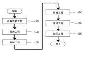
- FIG. 7 is a flowchart showing a sheet manufacturing method according to the sixth embodiment. Each step will be described with reference to FIG.
- Recycled recycled paper Pu prepared in advance is set in the raw material storage unit 210 and mounted in a raw material storage unit mounting unit (not shown) of the sheet manufacturing apparatus 1000.
- the sheet manufacturing apparatus 1000 is provided with a feeding roller 222a, and the feeding roller 222a is urged by the uppermost waste paper Pu set in the raw material storage unit 210.
- the feeding roller 222a that has been urged is rotated, and the uppermost sheet of the used waste paper Pu is sent to the next step.
- the feeding roller 222a can continuously feed the used paper Pu to the next process in a single sheet.
- the sterilization step (S2) is performed on the used waste paper Pu sent out in the raw material supply step (S1).
- the sterilization step (S2) in the sterilization unit 220, the used paper Pu is transported toward the manufacturing unit 100 on the sterilization processing transport unit 221 so that the sterilization process is performed over the entire surface of the sheet-shaped used paper Pu. It includes a sterilizing line irradiation step of irradiating ultraviolet rays UV of a sterilizing line, which is a sterilizing means, toward the used paper Pu from the ultraviolet irradiation apparatuses 223a and 223b.
- the first ultraviolet irradiation device 223a is provided on one side of the front and back sides of the used paper Pu
- the second ultraviolet irradiation device 223b is provided on the other side so that the front and back surfaces of the used paper Pu can be irradiated with ultraviolet rays UV.
- the used paper Pu sterilized by the sterilization step (S2) is transferred to the cutting step.
- the cutting step (S3) the used paper Pu conveyed and introduced from the sterilization step (S2) is formed into a few cm square strips by the crushing blade 11 provided in the crushing unit 10.
- the manufacturing unit 100 executed by the manufacturing unit 100 after the cutting process (S3) transferred from the sterilization process (S2), at least coarse fragments or defibration obtained from the used paper Pu sterilized by the sterilization process (S2)
- the living room environment where the sheet manufacturing apparatus 1000 and the sheet manufacturing apparatus 1000 are installed is preferably sterilized in advance.
- the strip formed in the cutting step (S3) is conveyed to the defibrating unit 20 and the defibrating step (S4) is executed.
- the defibrating device unit 23 provided in the defibrating unit 20 performs the defibrating by unraveling the chopped waste paper Pu into individual fibers.
- so-called dry defibrating is performed in which defibrating is performed in the atmosphere (in the air) without using a solvent, water, or the like. .
- the defibrated material obtained in the defibrating step (S4) is conveyed to the mixing unit 50, and the deposition step (S5) is performed.
- the deposition step (S5) includes a step of mixing the defibrated material with a binder resin powder for forming the fibrous defibrated material into a sheet-like recycled paper Pr in a pressurizing step described later.
- the binder resin powder is a thermoplastic resin or a thermosetting resin.
- the binder resin powder includes a colorant for coloring the fiber and an aggregation inhibitor for preventing the fiber from agglomerating according to the type of sheet produced.
- a flame retardant for making the fiber or the like difficult to burn may be included.
- the mixture in which the defibrated material and the binder resin powder are mixed is transported to the deposition unit 60, transported and deposited from the deposition unit 60 to the second web forming unit 70, and is a soft and bulging web containing a lot of air. W is formed on the mesh belt 71. And the web W is conveyed to a pressurization process.
- the web W is compressed and compressed by the pressurizing unit 81 included in the sheet forming unit 80, and the web W that is compressed and compressed by the pressurizing unit 81 is passed through the heating unit 82.
- a sheet S is formed. That is, the web W in which the defibrated material and the binder resin powder are mixed in the deposition step (S5) is fused by the heating unit 82, and the defibrated fibers are bound. By doing so, the web W can be formed on the sheet S.
- the heating unit 82 reaches a high temperature at which the resin can be melted, whereby the sheet S is sterilized to some extent.
- the sheet manufacturing method according to the present embodiment is completed when the sheet S is obtained by the pressing step (S6). However, after the pressing step (S6), the recycled paper Pr is formed into a desired size. A step of cutting the sheet S may be provided.
- the used paper Pu supplied in the raw material supply step (S1) is used and discharged in various usage environments, and it is extremely difficult to obtain used paper Pu sorted according to the level of bacterial contamination. It's okay. Therefore, according to the sheet manufacturing method according to the above-described embodiment, even when the used paper Pu is obtained from a wide range of suppliers, the used waste paper Pu as a raw material to be input is sterilized by providing the sterilization step (S2). Each process of sheet manufacture at can be executed. That is, it is possible to obtain used paper Pu that is a raw material that is not limited to a supplier.
- the sterilization process (S2) which shows the sheet manufacturing method concerning this embodiment illustrated using the sterilization part 220 which can perform the sterilization process by irradiation of ultraviolet-ray UV with which the sheet manufacturing apparatus 1000 concerning 1st Embodiment is equipped in the above-mentioned example.
- steam St with which the sheet manufacturing apparatus 1200 which concerns on 3rd Embodiment is equipped may be sufficient.
- the sterilization process (the humidification process by the sterilization part 610 which performs the sterilization process by irradiation of the microwave Mw from the microwave irradiation part 614 with which the sheet manufacturing apparatus 1300 which concerns on 4th Embodiment is equipped, and the microwave irradiation process ( S2) may be used.
- FIG. 8 is a flowchart showing a pulp-derived product manufacturing method according to the seventh embodiment.
- the pulp-derived product refers to a product manufactured using cellulose fiber pulp produced from plants such as wood as one of the raw materials.
- Recycled paper Pr produced by the sheet production method described in the above embodiment is also one of the pulp-derived products, but in the pulp-derived product production method according to the present embodiment, pulp as one of the raw materials of the final product A method for generating and obtaining the paper from the used paper Pu will be described.
- the steps from the raw material supply step (S1) to the defibration step (S4) shown in the flowchart of FIG. 7 in the sheet manufacturing method according to the sixth embodiment are common steps.
- the post-process including the mixing step (S10) is different. Therefore, the description from the raw material supply step (S1) to the defibration step (S4) in the flowchart of the pulp-derived product manufacturing method according to the present embodiment shown in FIG. 8 is omitted, and the subsequent step including the mixing step (S10) is described. To do.
- the defibrated material obtained up to the defibrating step (S4) is conveyed to the mixing unit 50, and the mixing step (S10) is performed.
- the mixing step (S10) since the manufactured product of the pulp manufacturing apparatus 2000 used in the pulp-derived product manufacturing method according to the present embodiment is pulp Fp, the deposition step (S5) of the sheet manufacturing method according to the sixth embodiment.
- the binder resin powder that has been mixed in the process is not used, but an additive material is mixed according to the intended use of the final product obtained by further processing the pulp Fp instead of the binder resin powder.
- the additive material include water-absorbing polymer fine particles, fragrance, antibacterial agent and antistatic agent.
- the mixing step (S10) the first selected material conveyed in the mixing unit 50 shown in FIG. 6 and the additive material supplied from the powder supply device 51 are mixed and transferred to the dispersing unit 2110.
- the dispersion unit 2110 loosens the entangled fibers of the defibrated material that is the first selected material, and lowers the fibers in the dispersion device unit 2112 while more uniformly dispersing the additive material in the fibers.
- a cylindrical sieve having a rotating mesh is used, and fibers or particles contained in the mixture that has passed through the mixing unit 50 are smaller than the opening size of the mesh of the sieve, that is, fibers that can pass through the mesh.
- the uniform pulp Fp can be formed by passing the particles.
- a discharging step (S11) is performed in which the pulp Fp lowered in the dispersing unit 2112 is discharged from the dispersing unit 2110 to a container that can be carried out.
- the storage bag 2300 installed in the storage container 2200 disposed in the discharge unit 2113 provided in the dispersion unit 2110 is decompressed by the suction device 2400, and the pulp Fp is sucked from the dispersion device unit 2112 to store the storage bag. It is stored in 2300.
- the obtained pulp Fp is supplied as one of the raw materials of the product. Since the pulp Fp obtained by the pulp-derived product manufacturing method according to the present embodiment is subjected to the sterilization step (S2) before the cutting step (S3) in which the used paper Pu as a raw material is input to the pulp manufacturing unit 2100, It can be suitably used for products requiring hygiene management, such as sanitary products such as disposable diapers and water absorbent pads, and sanitary products. Moreover, even if the used paper Pu as a raw material is obtained from a wide range of suppliers, according to the pulp-derived product manufacturing method according to the present embodiment, the used paper Pu that is input as a raw material is sterilized through the sterilization step (S2). The waste paper Pu can be obtained without being limited to the procurement source.
- the sterilization process (S2) which shows the pulp origin product manufacturing method which concerns on this embodiment uses the sterilization part 220 which can perform the sterilization process by irradiation of the ultraviolet-ray UV with which the pulp origin product manufacturing apparatus 2000 which concerns on 5th Embodiment is equipped in the above-mentioned example.
- seat manufacturing apparatus 1200 which concerns on 3rd Embodiment is equipped was provided. Also good. Or the humidification process by the pulp origin product manufacturing apparatus with which the sterilization part 610 which performs the sterilization process by irradiation of the microwave Mw from the microwave irradiation part 614 with which the sheet manufacturing apparatus 1300 which concerns on 4th Embodiment is equipped, and the microwave The sterilization process (S2) including an irradiation process may be sufficient.
Landscapes
- Engineering & Computer Science (AREA)
- Life Sciences & Earth Sciences (AREA)
- Textile Engineering (AREA)
- Manufacturing & Machinery (AREA)
- Wood Science & Technology (AREA)
- Forests & Forestry (AREA)
- Dry Formation Of Fiberboard And The Like (AREA)
- Paper (AREA)
- Processing Of Solid Wastes (AREA)
Abstract
調達する材料の自由度を高めることを可能にするシート製造装置および製造方法を得ることを目的とする。 原料を供給する原料供給部と、前記原料を解繊し原料繊維を形成する解繊部と、前記原料繊維を堆積させた堆積物を厚み方向に加圧する加圧部と、を備え、前記原料供給部は、前記原料を裁断する裁断部を含み、前記原料を前記裁断部への供給前に殺菌する殺菌部を備えるシート製造装置。
Description
本発明は、シート製造装置、シート製造方法、パルプ由来製品製造装置およびパルプ由来製品製造方法に関する。
資源活用の観点から紙のリサイクルは広く一般的になってきているが、従来は集積された古紙を、工業的に再生紙として製造するものであり、その方法は、いわゆる湿式と呼ばれる、古紙を水によって離解させて生成した再生パルプを再生紙に形成するものであった(特許文献1)。
集積される古紙は、多様な使われ方を経て排出された物であり、破損の状態、汚染の状態などの仕分けが容易にできるものではない。特に、細菌に汚染された古紙では目視による判定、排除は不可能であり、そこから再生された再生紙に細菌が付着した状態で消費者に供給することは回避しなければならない。
その点、特許文献1では、パルプ調整部に貯留される古紙離解の水に添加剤の一つとして抗菌剤、滅菌剤、殺菌剤などを添加することで、殺菌された再生パルプを生成し、再生紙への細菌などの汚染物質の残存を抑制することが開示されている。
しかし、湿式再生紙製造における水資源の多用、あるいは大型装置による工業的再生紙製造では古紙を集積する運送、など環境負荷が大きいものであった。そこで、近年の再生紙製造を事業所内で印刷され、廃却される書類を、事業所内で再生紙に成形し、印刷機へ印刷用紙として投入する技術として水を使わない乾式再生紙製造装置が開示されている(特許文献2~4)。
しかし、乾式による再生紙製造装置を開示する特許文献2~4では、特許文献1に開示されたような殺菌手段についての開示が無い。しかし、特許文献1に開示されたような大量の水を用いる殺菌手段をそのまま適用することはできない。従来の乾式による再生紙製造装置は、オフィス環境で使用された紙などの比較的衛生的な状態が維持された古紙を材料として使用する前提の装置に適用される技術と言える。そこで、調達する材料の自由度を高めることを可能にするシート製造装置および製造方法を得ることを目的とする。
本発明は、上述の課題の少なくとも一部を解決するためになされたものであり、以下の形態または適用例として実現することが可能である。
〔適用例1〕本適用例のシート製造装置は、原料を供給する原料供給部と、前記原料を解繊し原料繊維を形成する解繊部と、前記原料繊維を堆積させた堆積物を厚み方向に加圧する加圧部と、を備え、前記原料供給部は、前記原料を裁断する裁断部を含み、前記原料を前記裁断部への供給前に殺菌する殺菌部を備えることを特徴とする。
本適用例のシート製造装置は、原料となる使用済の用紙、すなわち古紙を解繊し原料繊維を形成する解繊部と、原料繊維を堆積させた堆積物を厚み方向に加圧する加圧部と、を備える、いわゆる乾式による再生紙を製造する装置である。原料となる古紙は、様々な使用環境において用いられ、排出されたものであり、細菌汚染の程度の高低によって仕分けされた古紙を入手することは極めて困難と言ってよい。
そこで本適用例のシート製造装置によれば、原料となる古紙を広範囲な調達先から入手しても、古紙の解繊前に殺菌部において古紙の状態で殺菌して投入することができる。すなわち、調達先に限定されない原料となる古紙の入手を可能とする。そして、古紙から再生されたシートは殺菌された状態で得られるため、使用者への細菌感染の危険性を低減することができる。言い換えると、従来よりも安全性が改善された再生シートを得ることができる。
〔適用例2〕上述の適用例において、前記原料はシート状の材料であって、前記原料を枚葉で前記裁断部へ搬送する搬送部を備え、前記殺菌部は前記搬送部を搬送される前記原料の枚葉に殺菌処理が可能となるように配置されていることを特徴とする。
上述の適用例によれば、原料がシート状の材料であり、枚葉、すなわち1枚ずつ殺菌部へ搬送し、殺菌処理が可能となり未殺菌処理の原料が裁断部に投入されることを防止する。
〔適用例3〕上述の適用例において、前記殺菌部は、殺菌線を照射する光照射部を備えていることを特徴とする。
上述の適用例によれば、殺菌力を持つ波長域の光線である殺菌線を原料に照射することで、容易に原料の殺菌処理を行うことができる。殺菌線としては波長260nm近傍の光線、いわゆる紫外線を用いることができる。
〔適用例4〕上述の適用例において、前記殺菌部は、殺菌薬液剤を吐出する液体吐出部を備えていることを特徴とする。
上述の適用例によれば、液状の殺菌薬液は原料の内部にまで浸透させることができ、高い殺菌効果を得ることができる。
〔適用例5〕上述の適用例において、前記殺菌部は、殺菌可能な温度に加熱された水蒸気を噴射する水蒸気噴射部を備えていることを特徴とする。
従来の殺菌方法で知られる煮沸消毒は沸騰水、いわゆる沸点100℃のお湯に浸漬して殺菌する方法である。上述の適用例によれば、水蒸気であれば水の沸点以上の温度まで加熱が可能であることから、容易に入手できる水を用いて原料の殺菌処理を行うことができる。また、水蒸気が原料を貫通して噴射されることで、原料の内部まで殺菌処理を行うことができる。
〔適用例6〕上述の適用例において、前記殺菌部は、前記原料を加湿する加湿部と、マイクロ波を照射するマイクロ波照射部と、を備えていることを特徴とする。
上述の適用例によれば、予め原料に水分を含ませ、マイクロ波によって水分子をマイクロ波加熱させて原料を加熱することができる。いわゆる加熱殺菌処理が容易に可能となる。また、原料に含ませた水分は、原料内部まで浸透していることで、原料内部まで高温にすることができ、高い殺菌効果を得ることができる。
〔適用例7〕本適用例のシート製造方法は、原料を供給する原料供給工程と、前記原料を殺菌する殺菌工程と、殺菌された前記原料を裁断する裁断工程と、裁断された前記原料を解繊する解繊工程と、前記解繊工程によって形成された前記原料繊維を堆積させる堆積工程と、前記堆積物を厚み方向に加圧する加圧工程と、を含むことを特徴とする。
本適用例のシート製造方法は、原料となる使用済の用紙、すなわち古紙を解繊し原料繊維を形成する解繊工程と、原料繊維を堆積させる堆積工程と、原料繊維を堆積させた堆積物を厚み方向に加圧する加圧工程と、を備える、いわゆる乾式による再生紙を製造する方法である。原料となる古紙は、様々な使用環境において用いられ、排出されたものであり、細菌汚染の程度の高低によって仕分けされた古紙を入手することは極めて困難と言ってよい。
そこで本適用例のシート製造方法によれば、原料となる古紙を広範囲な調達先から入手しても、古紙の解繊工程には、殺菌工程において古紙の状態で殺菌された原料を投入することができる。すなわち、調達先に限定されない原料となる古紙の入手を可能とする。そして、古紙から再生されたシートは殺菌された状態で得られるため、使用者への細菌感染の危険性を低減することができる。言い換えると、従来よりも安全性が改善された再生シートを得ることができる。
〔適用例8〕上述の適用例において、前記原料はシート状の材料であって、枚葉の前記原料に前記殺菌工程が実行された後、前記裁断工程が実行されることを特徴とする。
上述の適用例によれば、原料がシート状の材料であり、枚葉、すなわち1枚ずつ殺菌工程を実行して殺菌処理が可能となり未殺菌処理の原料が裁断工程に移行されることを防止する。
〔適用例9〕上述の適用例において、前記殺菌工程は、前記原料に殺菌線を照射する殺菌線照射工程を含むことを特徴とする。
上述の適用例によれば、殺菌力を持つ波長域の光線である殺菌線を原料に照射することで、容易に原料の殺菌処理を行うことができる。殺菌線としては波長260nm近傍の光線、いわゆる紫外線を用いることができる。
〔適用例10〕上述の適用例において、前記殺菌工程は、前記原料に殺菌剤を塗布する殺菌剤塗布工程を含むことを特徴とする。
上述の適用例によれば、塗布された殺菌剤が原料の内部にまで浸透し、高い殺菌効果を得ることができる。
〔適用例11〕上述の適用例において、前記殺菌工程は、前記原料に殺菌可能な温度に加熱された水蒸気を噴射する水蒸気噴射工程を含むことを特徴とする。
上述の適用例によれば、従来の殺菌方法で知られる煮沸消毒は沸騰水、いわゆる沸点100℃のお湯に浸漬して殺菌する方法である。上述の適用例によれば、水蒸気であれば水の沸点以上の温度まで加熱が可能であることから、容易に入手できる水を用いて原料の殺菌処理を行うことができる。また、水蒸気が原料を貫通して噴射されることで殺菌処理を行うことができる。
〔適用例12〕上述の適用例において、前記殺菌工程は、前記原料を加湿する加湿工程と、マイクロ波を照射するマイクロ波照射工程と、を含むことを特徴とする。
上述の適用例によれば、加湿工程によって予め原料に水分を含ませ、マイクロ波照射工程でマイクロ波によって水分子をマイクロ波加熱させて原料を加熱することができる。いわゆる加熱殺菌処理が容易に可能となる。また、原料に含ませた水分は、原料内部まで浸透していることで、原料内部まで高温にすることができ、高い殺菌効果を得ることができる。
〔適用例13〕本適用例のパルプ由来製品製造装置は、原料を供給する原料供給部と、前記原料を解繊し原料繊維を形成する解繊部と、を備え、前記原料供給部は、前記原料を裁断する裁断部と、前記原料を前記裁断部へ搬送する搬送部と、を含み、前記原料はシート状の材料であって、前記搬送部は前記原料を枚葉で前記裁断部へ搬送し、前記原料を前記裁断部への供給前に殺菌する殺菌部を備え、前記殺菌部は前記搬送部を搬送される前記原料の枚葉に殺菌処理が可能となるように配置されていることを特徴とする。
本適用例のパルプ由来製品製造装置は、原料となる使用済の用紙、すなわち古紙を解繊し原料繊維を形成する解繊部を備える、いわゆる乾式による再生パルプを製造する装置である。原料となる古紙は、様々な使用環境において用いられ、排出されたものであり、細菌汚染の程度の高低によって仕分けされた古紙を入手することは極めて困難と言ってよい。
パルプ由来製品とは、木材などの植物から生成されるセルロース繊維のパルプを原料の一つとして製造される製品のことをいう。本適用例のパルプ由来製品製造装置は、シート状の原料から製品の原料の一つとして供給されるパルプを製造する装置である。
そこで本適用例のパルプ由来製品製造装置によれば、原料となる古紙を広範囲な調達先から入手しても、古紙の解繊前に殺菌部において古紙の状態で殺菌して投入することができる。すなわち、調達先に限定されない原料となる古紙の入手を可能とする。また、原料がシート状の材料であり、枚葉、すなわち1枚ずつ殺菌部へ搬送し、殺菌処理が可能となり未殺菌処理の原料が裁断部に投入されることを防止することができる。従って、古紙から再生されたパルプは殺菌された状態で得られるため、使用者への細菌感染の危険性を低減することができる。言い換えると、従来よりも安全性が改善された再生パルプを得ることができる。特に、衛生管理が強く求められる製品、例えば紙おむつ、吸水パッドなどの衛生用品、生理用品などに好適に使用することができる。
〔適用例14〕本適用例のパルプ由来製品製造方法は、原料を供給する原料供給工程と、前記原料を殺菌する殺菌工程と、殺菌された前記原料を裁断する裁断工程と、裁断された前記原料を解繊する解繊工程と、を含み、前記原料はシート状の材料であって、枚葉の前記原料に前記殺菌工程が実行された後、前記裁断工程が実行されることを特徴とする。
本適用例のパルプ由来製品製造方法によれば、原料となる古紙を広範囲な調達先から入手しても、古紙の解繊工程の前に殺菌工程が実行され、殺菌された状態の古紙を投入することができる。すなわち、調達先に限定されない原料となる古紙の入手を可能とする。また、原料がシート状の材料であり、枚葉、すなわち1枚ずつ殺菌工程へ搬送し、殺菌処理が可能となり未殺菌処理の原料が裁断工程に移行されることを防止することができる。従って、古紙から再生されたパルプは殺菌された状態で得られるため、使用者への細菌感染の危険性を低減することができる。言い換えると、従来よりも安全性が改善された再生パルプを得ることができる。特に、衛生管理が強く求められる製品、例えば紙おむつ、吸水パッドなどの衛生用品、生理用品などに好適に使用することができる。
以下、図面を参照して、本発明に係る実施形態を説明する。
(第1実施形態)
図1は第1実施形態に係るシート製造装置の概略構成を示す構成図である。図1に示すシート製造装置1000は、原料としての古紙Puを再生紙Prへ形成する製造部100と、制御部110と、原料としての古紙Puを供給する原料供給部200と、を備える。製造部100は、裁断部としての粗砕部10と、解繊部20と、選別部30と、第1ウェブ形成部40と、回転体45と、混合部50と、堆積部60と、第2ウェブ形成部70と、シート形成部80と、切断部90と、を有している。
図1は第1実施形態に係るシート製造装置の概略構成を示す構成図である。図1に示すシート製造装置1000は、原料としての古紙Puを再生紙Prへ形成する製造部100と、制御部110と、原料としての古紙Puを供給する原料供給部200と、を備える。製造部100は、裁断部としての粗砕部10と、解繊部20と、選別部30と、第1ウェブ形成部40と、回転体45と、混合部50と、堆積部60と、第2ウェブ形成部70と、シート形成部80と、切断部90と、を有している。
選別部30と堆積部60は、バラバラにほぐしたパルプ繊維を、水を使わないで空気の流れに乗せて均一分散させ、金網上に吸い取らせてウェブを生成する装置である。このような加工方法はエアレイド法、加工機をエアレイド加工機と呼ばれている。
原料供給部200は、原料となる古紙Puを貯蔵する原料貯蔵部210と、板状の搬送部としての殺菌処理搬送部221と、古紙Puを製造部100の粗砕部10へ導入する導入経路230と、を備えている。原料貯蔵部210がシート製造装置1000の図示しない原料貯蔵部装着部に装着されると、シート製造装置1000に備える送出しローラー222aによって、一枚ごと、すなわち枚葉で殺菌処理搬送部221に向けて古紙Puが送り出される。これにより、後述の殺菌部220における未殺菌処理の古紙Puが製造部100に投入されることを防止する。
殺菌処理搬送部221に送り出された古紙Puは、少なくとも1対の第1搬送ローラー222bによって殺菌処理搬送部221上へ搬送される。殺菌処理搬送部221には貫通部221aが形成され、貫通部221aを挟むように対向させて殺菌線を照射する光照射部としての第1紫外線照射装置223aと、第2紫外線照射装置223bと、が配設されている。紫外線照射装置223a,223bは、共に貫通部221aに向けて殺菌線としての紫外線UVを出射するように配置されている。なお、貫通部221aには搬送される古紙Puの脱落防止のため、紫外線UVの照射量を減衰させない程度の粗さ網目を有する保持部材が備えられていてもよい。
第1搬送ローラー222bによって殺菌処理搬送部221上を搬送された古紙Puを、貫通部221a領域を通過させる時、紫外線照射装置223a,223bから紫外線UVを出射させることで、古紙Puの表裏面に紫外線UVが照射される。公知の通り、紫外線UVは殺菌線として多様な細菌に対して殺菌効果を発する光線であり、紫外線UVの中を古紙Puが通過することで、少なくとも古紙Puの表裏面に残存している細菌の多くを死滅させる、いわゆる殺菌することができる。
殺菌された古紙Puは、第2搬送ローラー222cによって殺菌処理搬送部221から搬出され、導入経路230へ送出される。導入経路230に搬入された古紙Puは導入経路230の導入路を介して、製造部100に備える粗砕部10へ投入される。
上述した、紫外線照射装置223a,223bを備え、古紙Puを殺菌搬送する、殺菌処理搬送部221と、搬送ローラー222b,222cと、を少なくとも含む殺菌部220が構成される。なお、送出しローラー222aは、古紙Puを一枚ごと、すなわち枚葉の古紙Puを原料貯蔵部210から送り出し、殺菌処理搬送部221でも、枚葉の古紙Puに対して紫外線UVが照射される。
原料供給部200によって供給される古紙Puは、様々な使用環境において用いられ、排出されたものであり、細菌汚染の程度の高低によって仕分けされた古紙Puを入手することは極めて困難と言ってよい。そこで原料となる古紙Puを広範囲な調達先から入手しても、本実施形態に係るシート製造装置1000の製造部100へ投入される古紙Puは殺菌された状態での投入を可能とする。すなわち、調達先に限定されない原料となる古紙Puの入手を可能とする。また、原料として古紙Puには限定されず、例えば、パルプシートなどの繊維を含むものであってもよく、粗砕部10へ供給、投入される前に、投入される原料に適用可能な原料搬送手段を備える殺菌部220によって原料を殺菌処理すればよい。
粗砕部10は、原料供給部200によって殺菌、供給された古紙Puを、空気中で裁断して細片にする。細片の形状や大きさは、例えば、数cm角の細片である。図示の例では、粗砕部10は、粗砕刃11を有し、粗砕刃11によって、投入された原料を裁断することができる。粗砕部10としては、例えば、シュレッダーを用いることができる。粗砕部10によって裁断された古紙Puは、解繊部20に備えるホッパー21で受けてから管22を介して、解繊装置部23に移送(搬送)される。
解繊装置部23は、粗砕部10によって裁断された原料を解繊する。ここで、本明細書における「解繊する」とは、複数の繊維が結着されることで形成されている被解繊物としての古紙Puを、繊維1本1本に解きほぐすことをいう。解繊装置部23は、原料に付着した樹脂粒やインク、トナー、にじみ防止剤等の物質を、繊維から分離させる機能をも有する。
解繊装置部23を通過し、形成された原料繊維を「解繊物」という。「解繊物」には、解きほぐされた解繊物繊維の他に、繊維を解きほぐす際に繊維から分離した樹脂(複数の繊維同士を結着させるための樹脂)粒や、インク、トナーなどの色剤や、にじみ防止材、紙力増強剤等の添加剤を含んでいる場合もある。
解繊装置部23は、溶剤、水などを使用せず、大気中(空気中)において、いわゆる乾式で解繊を行う。具体的には、解繊装置部23としては、インペラーミルを用いる。解繊装置部23は、原料を吸引し、解繊物を排出するような気流を発生させる機能を有している。これにより、解繊装置部23は、自ら発生する気流によって、導入口23aから原料を気流と共に吸引し、解繊処理して、解繊物を排出口23bへと搬送することができる。解繊装置部23を通過した解繊物は、管31を介して、選別部30に移送される。なお、解繊装置部23から選別部30に解繊物を搬送させるための気流は、解繊装置部23において発生する気流を利用してもよいし、ブロアー等の気流発生装置を設け、その気流を利用してもよい。
選別部30は、管31を介して解繊部20により解繊された解繊物を導入口32から選別装置部33に導入し、繊維の長さによって選別する。選別装置部33としては、例えば、篩(ふるい)を用いる。選別装置部33は、網(フィルター、スクリーン)を有し、網の目開きの大きさより小さい繊維または粒子(網を通過するもの、第1選別物)と、網の目開きの大きさより大きい繊維や未解繊片やダマ(網を通過しないもの、第2選別物)と、を分けることができる。例えば、第1選別物は、管44を介して、混合部50に移送される。第2選別物は、排出口34から管35を介して、解繊部20に戻される。具体的には、選別装置部33は、モーターによって回転駆動される円筒の篩である。選別装置部33の網としては、例えば、金網、切れ目が入った金属板を引き延ばしたエキスパンドメタル、金属板にプレス機等で穴を形成したパンチングメタルを用いる。
第1ウェブ形成部40は、選別部30を通過した第1選別物を、混合部50に搬送する。第1ウェブ形成部40は、メッシュベルト41と、張架ローラー42と、吸引部(サクション機構)43と、を含む。
吸引部43は、選別部30の開口(網の開口)を通過して空気中に分散された第1選別物をメッシュベルト41上に吸引することができる。第1選別物は、吸引部43によって選別部30から吸引され、移動するメッシュベルト41上に堆積し、ウェブVを形成する。メッシュベルト41、張架ローラー42および吸引部43の基本的な構成と、後述する第2ウェブ形成部70のメッシュベルト71、張架ローラー72および吸引部(サクション機構)73と、は同様である。
ウェブVは、選別部30および第1ウェブ形成部40を経ることにより、空気を多く含み柔らかくふくらんだ状態に形成される。メッシュベルト41に堆積されたウェブVは、管44へ投入され、混合部50へと搬送される。
回転体45は、ウェブVが混合部50に搬送される前に、ウェブVを切断することができる。図示の例では、回転体45は、基部45aと、基部45aから突出している突部45bと、を有している。突部45bは、例えば、板状の形状を有している。図示の例では、突部45bは4つ設けられ、4つの突部45bが等間隔に設けられている。基部45aが方向Rに回転することにより、突部45bは、基部45aを軸として回転することができる。回転体45によってウェブVを切断することにより、例えば、後述する堆積部60に供給される単位時間当たりの解繊物の量の変動を小さくすることができる。
混合部50は、選別部30を通過し、第1ウェブ形成部40により搬送された第1選別物と、結着樹脂粉体と、を混合する。混合部50は、結着樹脂粉体を供給する粉体供給装置51と、第1選別物と結着樹脂粉体とを搬送する管52と、ブロアー53と、を有している。管52は、管44と連続している。
混合部50では、ブロアー53によって気流を発生させ、管52中において、第1選別物と、粉体供給装置51から供給される結着樹脂粉体と、を混合させながら、搬送することができる。粉体供給装置51から供給される結着樹脂粉体は、複数の繊維を結着させることができる樹脂を含む。樹脂が供給された時点では、複数の繊維は結着されていない。樹脂は、後述するシート形成部80を通過する際に溶融させることで複数の繊維を結着させる。なお、第1選別物と結着樹脂粉体とを混合させる機構は、特に限定されない。
粉体供給装置51から供給される結着樹脂粉体は、熱可塑性樹脂や熱硬化性樹脂であり、例えば、AS樹脂、ABS樹脂、ポリプロピレン、ポリエチレン、ポリ塩化ビニル、ポリスチレン、アクリル樹脂、ポリエステル樹脂、ポリエチレンテレフタレート、ポリフェニレンエーテル、ポリブチレンテレフタレート、ナイロン、ポリアミド、ポリカーボネート、ポリアセタール、ポリフェニレンサルファイド、ポリエーテルエーテルケトン、などである。これらの樹脂を、単独または適宜混合して用いられる。
なお、粉体供給装置51から供給される結着樹脂粉体には、繊維を結着させる樹脂の他、製造されるシートの種類に応じて、繊維を着色するための着色剤や、繊維の凝集を防止するための凝集防止剤、繊維等が燃えにくくするための難燃剤などが含まれていてもよい。混合部50を通過した第1選別物と結着樹脂粉体との混合物は、管54を介して、堆積部60に移送される。
堆積部60は、混合部50を通過した混合物を導入口61から堆積装置部62に導入し、解繊物の絡み合った繊維をほぐして、空気中で分散させながら降らせる。さらに、堆積装置部62は、粉体供給装置51から供給される結着樹脂粉体の樹脂が繊維状である場合、絡み合った樹脂繊維をほぐす。これにより、堆積部60は、第2ウェブ形成部70に、混合物を均一性よく堆積させることができる。
堆積装置部62としては、回転する網を有する円筒の篩を用い、混合部50を通過した混合物に含まれる、篩の網の目の開口の大きさより小さい繊維または粒子、すなわち網を通過できる繊維または粒子を通過させる。堆積部60の構成は、例えば、選別部30の構成と同じである。
なお、堆積装置部62の「篩」は、特定の対象物を選別する機能を有していなくてもよい。すなわち、堆積装置部62として用いられる「篩」とは、網を備えたもの、という意味であり、堆積装置部62に導入された混合物の全てを通過させてもよい。
第2ウェブ形成部70は、堆積部60を通過した通過物を堆積して、堆積物としてのウェブWを形成する。第2ウェブ形成部70は、例えば、メッシュベルト71と、張架ローラー72と、吸引部(サクション機構)73と、を有している。
メッシュベルト71は、移動しながら、堆積部60の開口(網の開口)を通過した通過物を堆積する。メッシュベルト71は、張架ローラー72によって張架され、通過物を通しにくく空気を通す構成となっている。メッシュベルト71は、張架ローラー72が自転することによって連続的に移動する。堆積部60を通過した通過物が、連続的に移動するメッシュベルト71上に降り積もることにより、メッシュベルト71上にウェブWが形成される。
吸引部73は、メッシュベルト71の下方(堆積部60側とは反対側)に設けられている。吸引部73は、下方に向く気流(堆積部60からメッシュベルト71に向く気流)を発生させることができる。これにより、堆積部60からの通過物の排出速度を大きくすることができる。
以上のように、堆積部60および第2ウェブ形成部70(ウェブ形成工程)を経ることにより、空気を多く含み柔らかくふくらんだ状態のウェブWが形成される。メッシュベルト71に堆積されたウェブWは、シート形成部80へと搬送される。なお、図示の例では、ウェブWを調湿する調湿部74が設けられている。調湿部74は、ウェブWに対して水や水蒸気を添加して、ウェブWと水との量比を調節することができる。
シート形成部80は、メッシュベルト71に堆積したウェブWを加圧および加熱してシートSを形成する。シート形成部80では、ウェブWにおいて混ぜ合された解繊物および結着樹脂粉体の混合物に、熱を加えることにより、混合物中の複数の繊維を、互いに結着樹脂粉体を介して結着することができる。
シート形成部80は、ウェブWを加圧する加圧部81と、加圧部81により加圧されたウェブWを加熱する加熱部82と、を備えている。加圧部81は、一対のカレンダーローラー81a,81bで構成され、ウェブWに対して圧力を加える。ウェブWは、加圧されることによりその厚さが薄くされ、ウェブWの密度が高められる。加熱部82は、一対の加熱ローラー82a,82bを備えている。カレンダーローラー81a,81bにより加圧されたウェブWを、加熱ローラー82a,82bにより加熱し、樹脂を溶融させて繊維を結着させることによりシートSが形成される。ここで、加圧部81のカレンダーローラー81a,81bによってウェブWに印加される圧力は、加熱部82の加熱ローラー82a,82bによってウェブWに印加する圧力よりも高い圧力にすることができる。なお、カレンダーローラー81a,81bや加熱ローラー82a,82bの数は、特に限定されない。
なおシート形成部80には加熱部82を備えることにより、樹脂を溶融させて繊維を結着させるための加熱ローラー82a,82bによって、シートSへ形成すると同時に、樹脂を溶融させる温度まで加熱されることにより、ある程度の加熱殺菌の効果を得ることができる。よって、オフィス環境で使用された紙などの比較的衛生的な状態が維持された古紙を材料として使用する場合には、この加熱ローラー82a,82bによる加熱殺菌効果は有効である。
ただし、シートの最終製造工程で極度に高温にすると、シートにダメージを与えて、シートの強度を損ねる虞がある。本実施形態では、材料を解繊する前の工程で既に材料を殺菌しているので、加熱ローラー82a,82bによる加熱殺菌に頼らなくてもよい。よって、過度に加熱温度を上げる必要がないため、シートの強度劣化を抑えることができる。
切断部90は、シート形成部80によって形成されたシートSを切断する。図示の例では、切断部90は、シートSの搬送方向と交差する方向にシートSを切断する第1切断部91と、搬送方向に平行な方向にシートSを切断する、例えばローラーカッターなどの第2切断部92と、を有している。第2切断部92は、例えば、第1切断部91を通過したシートSを切断する。切断部90を通過させることで、シートSから切断された所定のサイズの単票の再生紙Prとして形成される。切断された単票の再生紙Prは、再生紙排出部300へと排出され、図示しない再生貯蔵手段へ搬送される。
(第2実施形態)
図2は第2実施形態に係るシート製造装置1100に備える原料供給部400の概略構成を示す構成図である。第2実施形態に係るシート製造装置1100は、第1実施形態に係るシート製造装置1000における原料供給部200を、原料供給部400に置き換えた形態である。よって、その他の構成において、第1実施形態に係るシート製造装置1000と同じ構成要素には同じ符号を付し、説明は省略する。
図2は第2実施形態に係るシート製造装置1100に備える原料供給部400の概略構成を示す構成図である。第2実施形態に係るシート製造装置1100は、第1実施形態に係るシート製造装置1000における原料供給部200を、原料供給部400に置き換えた形態である。よって、その他の構成において、第1実施形態に係るシート製造装置1000と同じ構成要素には同じ符号を付し、説明は省略する。
本実施形態に係るシート製造装置1100に備える原料供給部400は、原料となる古紙Puを貯蔵する原料貯蔵部210と、板状の殺菌処理搬送部411と、古紙Puを製造部100の粗砕部10へ導入する導入経路420と、を備えている。原料貯蔵部210がシート製造装置1100の図示しない原料貯蔵部装着部に装着されると、シート製造装置1100に備える送出しローラー412aによって、一枚ごと、すなわち枚葉で殺菌処理搬送部411に向けて古紙Puが送り出される。
殺菌処理搬送部411に送り出された古紙Puは、少なくとも1対の第1搬送ローラー412bによって殺菌処理搬送部411上へ搬送される。殺菌処理搬送部411の重力方向の上部には、殺菌処理搬送部411に対向させて殺菌薬液剤を吐出する薬液噴霧部413bを備える液体吐出部413が配設されている。液体吐出部413は、噴霧させる薬液を図示しない薬液供給部から導入し貯留する貯留部と、霧状に吐出可能な圧力を薬液に付加する加圧手段と、を備える吐出駆動部413aと、薬液を霧状に吐出する薬液噴霧部413bと、を備えている。
第1搬送ローラー412bによって殺菌処理搬送部411上を搬送された古紙Puは、薬液噴霧部413bからの霧状薬液Msの被噴霧領域を通過し、古紙Puに殺菌薬液剤が塗布される。殺菌薬液としては、公知の薬液剤が用いられるが、例えばアルコール類、過酸化水素水、グルコン酸クロルヘキシジン、次亜塩素酸ナトリウム、オゾン水など、適宜、選択すればよい。
殺菌薬液剤が塗布された古紙Puは、第2搬送ローラー412cによって殺菌処理搬送部411から搬出され、導入経路420へ送出される。導入経路420の途中に、導入経路420の内部の導入路420a内に、古紙Puに塗布された殺菌薬液剤の液体成分を乾燥させる乾燥気体を送出する乾燥装置430を備えている。乾燥装置430では、乾燥気体として例えば、低湿度空気、あるいは加熱空気を図示しない送風手段によって送出口430aから導入路420a内に送出する。そして、導入路420a内で乾燥された古紙Puは、製造部100に備える粗砕部10へ投入される。
本実施形態に係るシート製造装置1100における原料供給部400は、少なくとも殺菌薬液剤を吐出する液体吐出部413と、殺菌処理された古紙Puを搬送すると殺菌処理搬送部411と、搬送ローラー412b,412cと、を含む殺菌部410が構成される。これにより、原料となる古紙Puを広範囲な調達先から入手しても、本実施形態に係るシート製造装置1100の製造部100へ投入される古紙Puは殺菌された状態での投入を可能とする。すなわち、調達先に限定されない原料となる古紙Puの入手を可能とする。
(変形例)
上述した第2実施形態に係るシート製造装置1100の変形例の概略構成を図3に示す。図3に示す変形例のシート製造装置1100Aは、第2実施形態に示すシート製造装置1100に備える粗砕部10に殺菌部410の構成をさせた構成である。よって、第2実施形態に係るシート製造装置1100と同じ構成要素には同じ符号を付し、説明は省略する。
上述した第2実施形態に係るシート製造装置1100の変形例の概略構成を図3に示す。図3に示す変形例のシート製造装置1100Aは、第2実施形態に示すシート製造装置1100に備える粗砕部10に殺菌部410の構成をさせた構成である。よって、第2実施形態に係るシート製造装置1100と同じ構成要素には同じ符号を付し、説明は省略する。
図3に示すシート製造装置1100Aは、原料貯蔵部210のセットされた古紙Puが図示しない搬送手段によって粗砕部10Aに向けて搬送される。粗砕部10Aは、粗砕刃11を備え、粗砕刃11が投入された古紙Puを空気中で裁断して細片にする。
粗砕部10Aは、古紙Puを粗砕刃11に導入させるガイド部12を備えている。そしてガイド部12の内側に向けて霧状薬液Msの噴霧が可能となるように液体吐出部441が装着されている。液体吐出部441は、噴霧させる薬液を図示しない薬液供給部から導入し貯留する貯留部と、霧状に吐出可能な圧力を薬液に付加する加圧手段と、を備える吐出駆動部441aと、薬液を霧状に吐出する薬液噴霧部441bと、を備えている。
搬送手段から粗砕部10Aのガイド部12へ搬送されてきた古紙Puが粗砕刃11に導入される前に、ガイド部12に装着された液体吐出部441の薬液噴霧部441bから、霧状薬液Msが古紙Puに向けて噴霧する。噴霧される薬液には殺菌薬液が用いられ、殺菌薬液としては公知の薬液剤、例えばアルコール類、過酸化水素水、グルコン酸クロルヘキシジン、次亜塩素酸ナトリウム、オゾン水など、適宜、選択すればよい。
上述したように、変形例のシート製造装置1100Aでは、ガイド部12と、液体吐出部441と、によって、粗砕刃11の直前において殺菌処理を可能とする殺菌部440を構成し、製造部100Aを経て殺菌処理された状態で再生紙Prを得ることができる。
(第3実施形態)
図4は第3実施形態に係るシート製造装置1200に備える原料供給部500の概略構成を示す構成図である。第3実施形態に係るシート製造装置1200は、第1実施形態に係るシート製造装置1000における原料供給部200を、原料供給部500に置き換えた形態である。よって、その他の構成において、第1実施形態に係るシート製造装置1000と同じ構成要素には同じ符号を付し、説明は省略する。
図4は第3実施形態に係るシート製造装置1200に備える原料供給部500の概略構成を示す構成図である。第3実施形態に係るシート製造装置1200は、第1実施形態に係るシート製造装置1000における原料供給部200を、原料供給部500に置き換えた形態である。よって、その他の構成において、第1実施形態に係るシート製造装置1000と同じ構成要素には同じ符号を付し、説明は省略する。
本実施形態に係るシート製造装置1200に備える原料供給部500は、原料となる古紙Puを貯蔵する原料貯蔵部210と、板状の殺菌処理搬送部511と、古紙Puを製造部100の粗砕部10へ導入する導入経路520と、を備えている。原料貯蔵部210がシート製造装置1200の図示しない原料貯蔵部装着部に装着されると、シート製造装置1200に備える送出しローラー512aによって、一枚ごと、すなわち枚葉で殺菌処理搬送部511に向けて古紙Puが送り出される。
殺菌処理搬送部511に送り出された古紙Puは、少なくとも1対の第1搬送ローラー512bによって殺菌処理搬送部511上へ搬送される。殺菌処理搬送部511には貫通部511aが形成され、貫通部511aには搬送される古紙Puの脱落防止と、後述する高温水蒸気が通過可能な網目を有する保持部材511bが備えられている。殺菌処理搬送部511の貫通部511aの重力方向の上部には、殺菌手段としての水蒸気噴射装置513が配設されている。
水蒸気噴射装置513は、水蒸気発生器513aと、水蒸気噴射部513bと、を備え、水蒸気噴射部513bは、高温水蒸気Stを殺菌処理搬送部511の貫通部511aに備える保持部材511bに向けて噴射する。
第1搬送ローラー512bによって殺菌処理搬送部511上を搬送された古紙Puは、水蒸気噴射装置513の水蒸気噴射部513bから噴射される高温水蒸気Stの噴射領域を通過することで古紙Puに高温水蒸気Stが吹き付けられ、高温水蒸気Stの一部は古紙Puを通過して、保持部材511bを介して貫通部511aを抜けてゆく。これにより、古紙Puの表面と共に内部まで高温水蒸気Stによって殺菌される。なお、高温水蒸気Stの温度は、いわゆる煮沸消毒に相当する100℃を超え、原料である木材由来パルプからなる古紙Puの熱分解による炭化に至らない温度以下の温度であることが好ましい。また、高温水蒸気Stには、古紙Puを貫通可能な圧力を付加することが好ましい。
高温水蒸気Stが噴霧された古紙Puは、第2搬送ローラー512cによって殺菌処理搬送部511から搬出され、導入経路520へ送出される。導入経路520の途中に、導入経路520の内部の導入路520a内に、古紙Puを乾燥させる乾燥気体を送出する乾燥装置530を備えている。殺菌処理搬送部511において高温水蒸気Stが噴霧された古紙Puは水蒸気によって付与された水分を含んだ状態となるが、合わせて水蒸気温度まで高温に加温されるため、高温水蒸気Stの噴霧領域から離脱すると、高温水蒸気Stによって古紙Puに付加された熱量によって、付加された水分は蒸発、乾燥する。しかし、古紙Puが含有した水分を確実に除去するために乾燥装置530を備えることが好ましい。
乾燥装置530では、乾燥気体として例えば、低湿度空気、あるいは加熱空気を図示しない送風手段によって送出口530aから導入路520a内に送出する。そして、導入路520a内で乾燥された古紙Puは、製造部100に備える粗砕部10へ投入される。
本実施形態に係るシート製造装置1200における原料供給部500は、少なくとも高温水蒸気を噴出する水蒸気噴射装置513と、殺菌処理された古紙Puを搬送すると殺菌処理搬送部511と、搬送ローラー512b,512cと、を含む殺菌部510が構成される。これにより、原料となる古紙Puを広範囲な調達先から入手しても、本実施形態に係るシート製造装置1200の製造部100へ投入される古紙Puは、殺菌された状態での投入を可能とする。すなわち、調達先に限定されない原料となる古紙Puの入手を可能とする。
(第4実施形態)
図5は第4実施形態に係るシート製造装置1300に備える原料供給部600の概略構成を示す構成図である。なお本実施形態に係るシート製造装置1300は、第1実施形態に係るシート製造装置1000に備える製造部100および再生紙排出部300は同じ構成である。言い換えると、第3実施形態に係るシート製造装置1300は、シート製造装置1000における原料供給部200を、原料供給部600に置き換えた形態であるので、シート製造装置1000と同じ構成要素には同じ符号を付し、説明は省略する。
図5は第4実施形態に係るシート製造装置1300に備える原料供給部600の概略構成を示す構成図である。なお本実施形態に係るシート製造装置1300は、第1実施形態に係るシート製造装置1000に備える製造部100および再生紙排出部300は同じ構成である。言い換えると、第3実施形態に係るシート製造装置1300は、シート製造装置1000における原料供給部200を、原料供給部600に置き換えた形態であるので、シート製造装置1000と同じ構成要素には同じ符号を付し、説明は省略する。
本実施形態に係るシート製造装置1300に備える原料供給部600は、原料となる古紙Puを貯蔵する原料貯蔵部210と、板状の殺菌処理搬送部611と、古紙Puを製造部100の粗砕部10へ導入する導入経路620と、を備えている。原料貯蔵部210がシート製造装置1300の図示しない原料貯蔵部装着部に装着されると、シート製造装置1300に備える送出しローラー612aによって、一枚ごと、すなわち枚葉で殺菌処理搬送部511に向けて古紙Puが送り出される。
殺菌処理搬送部611に送り出された古紙Puは、少なくとも1対の第1搬送ローラー612bによって殺菌処理搬送部611上へ搬送される。殺菌処理搬送部611の重力方向の上部には、殺菌処理搬送部611に対向させて水滴を吐出する水吐出部613bを備える加湿部613が配設されている。加湿部613は、吐出させる図示しない水供給部から導入し貯留する貯留部と、吐出可能な圧力を水に付加する加圧手段と、を備える吐出駆動部613aと、水滴を吐出する水吐出部613bと、を備えている。なお、本例では液滴状の水を吐出する形態を例示しているが、水を霧状に噴霧することができる水吐出部613bであってもよい。
第1搬送ローラー612bによって殺菌処理搬送部611上を搬送された古紙Puは、水吐出部613bから吐出された水滴Wdの吐出領域を通過し、古紙Puは所望の水分が含浸、加湿される。加湿された古紙Puは第2搬送ローラー612cによって、搬送方向に備えるマイクロ波照射部614に搬送される。
マイクロ波照射部614は、マイクロ波発生部614aが、マイクロ波Mwの外部への漏れを遮蔽する筐体614bの内部に配設され、筐体614b内に搬送される古紙Puに向けてマイクロ波Mwが照射可能に配置されている。そして、加湿された古紙Puがマイクロ波照射部614の筐体614b内に搬送され、古紙Puに向けてマイクロ波Mwがマイクロ波発生部614aから照射される。そして、マイクロ波Mwによって古紙Puに含まれる水分子がマイクロ波加熱され、古紙Puを高温にすることで古紙Puに残存する細菌を殺菌する。
マイクロ波照射部614によってマイクロ波加熱された古紙Puは、第3搬送ローラー612dによって殺菌処理搬送部611から搬出され、導入経路620へ送出される。導入経路620の途中に、導入経路620の内部の導入路620a内に、古紙Puを乾燥させる乾燥気体を送出する乾燥装置630を備えている。殺菌処理搬送部611において加湿部613から水滴Wdが吐出、加湿された古紙Puは水分を含んだ状態となるが、マイクロ波照射部614におけるマイクロ波加熱により高温状態となり古紙Puに含有した水分は蒸発し、古紙Puは乾燥する。しかし、古紙Puが含有した水分を確実に除去するために乾燥装置630を備えることが好ましい。
乾燥装置630では、乾燥気体として例えば、低湿度空気、あるいは加熱空気を図示しない送風手段によって送出口630aから導入路620a内に送出する。そして、導入路620a内で乾燥された古紙Puは、製造部100に備える粗砕部10へ投入される。
本実施形態に係るシート製造装置1300における原料供給部600は、少なくとも加湿部613と、マイクロ波照射部614と、殺菌処理された古紙Puを搬送する殺菌処理搬送部611と、搬送ローラー612b,612c,612dと、を含む殺菌部610が構成される。これにより、原料となる古紙Puを広範囲な調達先から入手しても、本実施形態に係るシート製造装置1300の製造部100へ投入される古紙Puは、殺菌された状態での投入を可能とする。すなわち、調達先に限定されない原料となる古紙Puの入手を可能とする。
本実施形態に係るシート製造装置1000,1100,1200,1300のいずれかによって製造されたシートは、シートを加工するシート加工機を用いて各種シート加工品の材料になる。従来、紙コップや紙皿、紙製ランチボックスなどの使い捨て食器は、衛生上の問題から、バージンパルプを用いて製造されていた。しかし、本実施形態で製造された再生紙は衛生的なシートであるので、従来は再生紙で製造できなかった紙製食器などに加工できる。なお、上述した実施形態は乾式の再生紙製造装置に関して説明したが、本願発明は乾式の装置に限定するものではなく、湿式の再生紙製造装置にも適用可能である。
(第5実施形態)
図6は第5実施形態に係るパルプ由来製品製造装置の概略構成を示す構成図である。ここで、パルプ由来製品とは、木材などの植物から生成されるセルロース繊維のパルプを原料の一つとして製造される製品のことをいう。上述の実施形態で説明したシート製造装置1000,1100,1200,1300によって製造される再生紙Prもパルプ由来製品の一つではあるが、本実施形態に係るパルプ由来製品製造装置では、最終製品の原料の一つとしてのパルプを古紙Puから生成し、得ることができる装置を説明する。
図6は第5実施形態に係るパルプ由来製品製造装置の概略構成を示す構成図である。ここで、パルプ由来製品とは、木材などの植物から生成されるセルロース繊維のパルプを原料の一つとして製造される製品のことをいう。上述の実施形態で説明したシート製造装置1000,1100,1200,1300によって製造される再生紙Prもパルプ由来製品の一つではあるが、本実施形態に係るパルプ由来製品製造装置では、最終製品の原料の一つとしてのパルプを古紙Puから生成し、得ることができる装置を説明する。
図6に示す第5実施形態に係るパルプ由来製品製造装置2000(以下、パルプ製造装置2000という)は、第1実施形態に係るシート製造装置1000に備える殺菌部220を含む原料供給部200を備えている。また、第1実施形態に係るシート製造装置1000に備える製造部100に備える構成要素の一部を備えるパルプ製造部2100を備えている。従って、第1実施形態に係るシート製造装置1000と同じ構成要素には同じ符号を付し、説明は省略する。
上述したが、パルプ製造装置2000は原料供給部200と、パルプ製造部2100と、を備え、パルプ製造部2100において製造されたパルプFpは収納容器2200内に配設された収納袋2300内に収容される。言い換えると、パルプ製造装置2000はパルプFpを製造製品とする装置である。
パルプ製造装置2000は、原料供給部200から古紙Puが供給される。供給される古紙Puは上述した通り、殺菌部220に備える紫外線照射装置223a,223bから照射される紫外線UVによってパルプ製造部2100への投入前に殺菌処理されている。
原料供給部200において殺菌された古紙Puはパルプ製造部2100に備える粗砕部10に投入され、粗砕部10において裁断、細片化されて解繊部20に投入される。解繊部20では、解繊装置部23において細片化された原料が解繊され、解繊物に形成される。
解繊物は続いて選別部30に移送され、解繊物を繊維の長さによって例えば篩などの選別手段を用いて選別し、選別部30を通過した第1選別物が第1ウェブ形成部40を介して混合部50に搬送される。混合部50では、本実施形態に係るパルプ製造装置2000の製造製品がパルプFpであることから、第1実施形態に係るシート製造装置1000において混合される結着樹脂粉体は用いず、結着樹脂粉体に替えてパルプFpを更に加工することで得る予定の最終製品の用途に応じた添加材料が混合される。添加材料として例えば、吸水ポリマー微粒子、芳香剤、抗菌剤、帯電防止剤などが挙げられる。従って、粉体供給装置51からは混合される添加材料が供給される。
混合部50において生成された第1選別物と添加材料との混合物は、分散部2110に移送される。分散部2110は、第1実施形態に係るシート製造装置1000の製造部100に備える堆積部60と同じ機構を備えるものである。
分散部2110は、混合部50を通過した混合物を導入口2111から分散装置部2112に導入し、第1選別物である解繊物の絡み合った繊維をほぐし、添加材料をより均一に繊維の中に分散させながら分散装置部2112内で降らせてゆく。分散装置部2112としては、回転する網を有する円筒の篩を用い、混合部50を通過した混合物に含まれる、篩の網の目の開口の大きさより小さい繊維または粒子、すなわち網を通過できる繊維または粒子を通過させる。分散部2110の構成は、例えば、選別部30の構成と同じである。
分散装置部2112によって均一に混合された繊維と添加材料との混合物としてのパルプFpは、排出部2113から収納容器2200に設置した収納袋2300内に導入される。なお、収納袋2300へのパルプFpの導入を容易にするために、収納袋2300内を減圧する吸引装置2400を備えていてもよい。
製造されたパルプFpは、製品の原料の一つとして供給される。上述したように、本実施形態に係るパルプ製造装置2000によって形成されるパルプFpは、原料である古紙Puを原料供給部200における殺菌部220によって、パルプ製造部2100に投入前に殺菌処理が行われるため、衛生管理が求められる各種製品に使用することができる。
分散装置部2112は回転式の網目ドラムの構造になっているので、このドラムの網目の条件や回転条件を適宜設定することで、投入された解繊物は最終製品に好適な状態にほぐされる。パルプFpを均一密度の綿状体にすれば、この綿状体を所定厚みのシート状に積層することで、紙おむつやナプキン、ペーパータオルなどの吸水パッドに加工できる。また、この綿状体を吸水性材料からなる筒袋に装填することで、タンポンに加工できる。本実施形態で製造されるパルプFpは、綿状体を材料にする各種の従来加工機をそのまま用いて、様々な衛生用品、生理用品に加工できる。
更に、パルプFpを所定の形状の型で成形することで、インクジェットプリンターの余剰インクを吸収するインク吸収体を製造することができる。また、スピーカーボックスの内部に貼る吸音材や、各種工業製品の騒音を抑制する吸音材、熱の伝達を抑制する断熱材や、ワレモノを輸送する時に用いる緩衝材など、綿状体を材料とする様々な製品へ適用できる。また、紙コップなどの紙製食器は、通常はシートを加工して製造するのが一般的であるが、綿状体であるパルプFpをエアレイド加工機によって成形することができる。この方法は、特開2001-232611号公報で開示されている。すなわち、本実施形態のパルプ由来製品製造装置は様々な製品へ適用できる。
また、原料となる古紙Puを広範囲な調達先から入手しても、本実施形態に係るパルプ製造装置2000のパルプ製造部2100へ投入される古紙Puは殺菌された状態での投入が可能となり、調達先に限定されない原料となる古紙Puの入手を可能とする。なお、原料として古紙Puには限定されず、例えば、パルプシートなどの繊維を含むものであってもよく、粗砕部10へ投入される前に、選択された原料に適用可能な原料搬送手段を備える殺菌部220によって原料を殺菌処理すればよい。
上述したパルプ製造装置2000は、紫外線UVによる殺菌処理を行う殺菌部220を備える原料供給部200を備える形態としたが、第2実施形態に係るシート製造装置1100に備える液体吐出部413からの霧状薬液Msの噴霧による殺菌処理を行う殺菌部410を備える原料供給部400、あるいは第3実施形態に係るシート製造装置1200に備える高温水蒸気Stの噴射による殺菌処理を行う殺菌部510を備える原料供給部500、あるいは第4実施形態に係るシート製造装置1300に備えるマイクロ波照射部614からのマイクロ波Mwの照射による殺菌処理を行う殺菌部610を備える原料供給部600のいずれを備えていてもよい。
(第6実施形態)
第6実施形態として、第1実施形態に係るシート製造装置1000によるシート製造方法を説明する。図7は第6実施形態に係るシート製造方法を示すフローチャートである。なお各工程の説明は、図1を用いて行う。
第6実施形態として、第1実施形態に係るシート製造装置1000によるシート製造方法を説明する。図7は第6実施形態に係るシート製造方法を示すフローチャートである。なお各工程の説明は、図1を用いて行う。
(原料供給工程)
予め準備された再生用の古紙Puを原料貯蔵部210にセットし、シート製造装置1000の図示しない原料貯蔵部装着部に装着する。シート製造装置1000には送出しローラー222aが備えられ、送出しローラー222aは原料貯蔵部210にセットされた最上部の古紙Puに付勢される。そして原料供給工程(S1)では、付勢させた送出しローラー222aを回動させ、セットされた古紙Puの最上部の一枚を、次の工程に送り出す。送出しローラー222aは、連続して枚葉で次工程に向けて古紙Puを送り出すことができる。
予め準備された再生用の古紙Puを原料貯蔵部210にセットし、シート製造装置1000の図示しない原料貯蔵部装着部に装着する。シート製造装置1000には送出しローラー222aが備えられ、送出しローラー222aは原料貯蔵部210にセットされた最上部の古紙Puに付勢される。そして原料供給工程(S1)では、付勢させた送出しローラー222aを回動させ、セットされた古紙Puの最上部の一枚を、次の工程に送り出す。送出しローラー222aは、連続して枚葉で次工程に向けて古紙Puを送り出すことができる。
(殺菌工程)
原料供給工程(S1)によって送り出された枚葉の古紙Puは、殺菌工程(S2)が実行される。殺菌工程(S2)では、シート状の古紙Pu全面に亘って殺菌処理が行われるよう、殺菌部220では殺菌処理搬送部221上を古紙Puが製造部100に向けて搬送移動される間に、殺菌手段である殺菌線の紫外線UVを紫外線照射装置223a,223bから古紙Puに向けて照射する殺菌線照射工程を含む。更に、古紙Puの表裏面に紫外線UVの照射が可能となるよう、古紙Puに対して表裏側の一方の側に第1紫外線照射装置223aが、他方の側に第2紫外線照射装置223bが、配置されている。殺菌工程(S2)によって殺菌処理された古紙Puは、裁断工程に移行される。
原料供給工程(S1)によって送り出された枚葉の古紙Puは、殺菌工程(S2)が実行される。殺菌工程(S2)では、シート状の古紙Pu全面に亘って殺菌処理が行われるよう、殺菌部220では殺菌処理搬送部221上を古紙Puが製造部100に向けて搬送移動される間に、殺菌手段である殺菌線の紫外線UVを紫外線照射装置223a,223bから古紙Puに向けて照射する殺菌線照射工程を含む。更に、古紙Puの表裏面に紫外線UVの照射が可能となるよう、古紙Puに対して表裏側の一方の側に第1紫外線照射装置223aが、他方の側に第2紫外線照射装置223bが、配置されている。殺菌工程(S2)によって殺菌処理された古紙Puは、裁断工程に移行される。
(裁断工程)
裁断工程(S3)では、殺菌工程(S2)から搬送、投入された古紙Puを粗砕部10に備える粗砕刃11によって数cm角の細片に形成する。なお、殺菌工程(S2)から移行した裁断工程(S3)以降の製造部100によって実行される後述の工程では、少なくとも殺菌工程(S2)によって殺菌された古紙Puから得られる粗砕片、あるいは解繊物が細菌に汚染されることを防止するため、シート製造装置1000およびシート製造装置1000が設置される居室環境は、予め殺菌処理されていることが好ましい。
裁断工程(S3)では、殺菌工程(S2)から搬送、投入された古紙Puを粗砕部10に備える粗砕刃11によって数cm角の細片に形成する。なお、殺菌工程(S2)から移行した裁断工程(S3)以降の製造部100によって実行される後述の工程では、少なくとも殺菌工程(S2)によって殺菌された古紙Puから得られる粗砕片、あるいは解繊物が細菌に汚染されることを防止するため、シート製造装置1000およびシート製造装置1000が設置される居室環境は、予め殺菌処理されていることが好ましい。
(解繊工程)
裁断工程(S3)で形成された細片は解繊部20に搬送され解繊工程(S4)が実行される。解繊工程(S4)では、解繊部20に備える解繊装置部23によって、細片化された古紙Puを、繊維1本1本に解きほぐす、解繊が実行される。本実施形態に係る解繊工程(S4)は、解繊装置部23において、溶剤、水などを使用せず、大気中(空気中)において解繊を行う、いわゆる乾式での解繊が行なわれる。
裁断工程(S3)で形成された細片は解繊部20に搬送され解繊工程(S4)が実行される。解繊工程(S4)では、解繊部20に備える解繊装置部23によって、細片化された古紙Puを、繊維1本1本に解きほぐす、解繊が実行される。本実施形態に係る解繊工程(S4)は、解繊装置部23において、溶剤、水などを使用せず、大気中(空気中)において解繊を行う、いわゆる乾式での解繊が行なわれる。
(堆積工程)
解繊工程(S4)によって得られた解繊物は、混合部50に搬送され、堆積工程(S5)が実行される。堆積工程(S5)は、解繊物に後述する加圧工程において繊維状の解繊物からシート状の再生紙Prへ形成するための結着樹脂粉体を混合する工程を含む。結着樹脂粉体は、熱可塑性樹脂や熱硬化性樹脂であり、例えば、AS樹脂、ABS樹脂、ポリプロピレン、ポリエチレン、ポリ塩化ビニル、ポリスチレン、アクリル樹脂、ポリエステル樹脂、ポリエチレンテレフタレート、ポリフェニレンエーテル、ポリブチレンテレフタレート、ナイロン、ポリアミド、ポリカーボネート、ポリアセタール、ポリフェニレンサルファイド、ポリエーテルエーテルケトン、などである。これらの樹脂を、単独または適宜混合して用いられる。また、結着樹脂粉体には、繊維を結着させる樹脂の他、製造されるシートの種類に応じて、繊維を着色するための着色剤や、繊維の凝集を防止するための凝集防止剤、繊維等が燃えにくくするための難燃剤などが含まれていてもよい。
解繊工程(S4)によって得られた解繊物は、混合部50に搬送され、堆積工程(S5)が実行される。堆積工程(S5)は、解繊物に後述する加圧工程において繊維状の解繊物からシート状の再生紙Prへ形成するための結着樹脂粉体を混合する工程を含む。結着樹脂粉体は、熱可塑性樹脂や熱硬化性樹脂であり、例えば、AS樹脂、ABS樹脂、ポリプロピレン、ポリエチレン、ポリ塩化ビニル、ポリスチレン、アクリル樹脂、ポリエステル樹脂、ポリエチレンテレフタレート、ポリフェニレンエーテル、ポリブチレンテレフタレート、ナイロン、ポリアミド、ポリカーボネート、ポリアセタール、ポリフェニレンサルファイド、ポリエーテルエーテルケトン、などである。これらの樹脂を、単独または適宜混合して用いられる。また、結着樹脂粉体には、繊維を結着させる樹脂の他、製造されるシートの種類に応じて、繊維を着色するための着色剤や、繊維の凝集を防止するための凝集防止剤、繊維等が燃えにくくするための難燃剤などが含まれていてもよい。
解繊物と結着樹脂粉体とが混合された混合物は、堆積部60へ搬送され、堆積部60から第2ウェブ形成部70に搬送、堆積され、空気を多く含み柔らかくふくらんだ状態のウェブWがメッシュベルト71上に形成される。そして、ウェブWは加圧工程へ搬送される。
(加圧工程)
加圧工程(S6)は、シート形成部80に備える加圧部81によってウェブWを加圧圧縮し、加圧部81によって加圧圧縮されたウェブWを加熱する加熱部82を通過することによりシートSを形成する。すなわち、堆積工程(S5)において解繊物と、結着樹脂粉体と、が混合されたウェブWが、加熱部82により結着樹脂粉体が熱溶融し、解繊された繊維を結着させることでウェブWをシートSへ形成することができる。この時、加熱部82は樹脂を溶融可能とする高温に達することで、シートSはある程度の加熱殺菌がなされる。
加圧工程(S6)は、シート形成部80に備える加圧部81によってウェブWを加圧圧縮し、加圧部81によって加圧圧縮されたウェブWを加熱する加熱部82を通過することによりシートSを形成する。すなわち、堆積工程(S5)において解繊物と、結着樹脂粉体と、が混合されたウェブWが、加熱部82により結着樹脂粉体が熱溶融し、解繊された繊維を結着させることでウェブWをシートSへ形成することができる。この時、加熱部82は樹脂を溶融可能とする高温に達することで、シートSはある程度の加熱殺菌がなされる。
加圧工程(S6)によって、シートSが得られることで本実施形態に係るシート製造方法は終了するが、加圧工程(S6)の後、所望の大きさの再生紙Prに成形するためにシートSを切断する工程を設けてもよい。
原料供給工程(S1)において供給される古紙Puは、様々な使用環境において用いられ、排出されたものであり、細菌汚染の程度の高低によって仕分けされた古紙Puを入手することは極めて困難と言ってよい。そこで上述の本実施形態に係るシート製造方法によれば、古紙Puを広範囲な調達先から入手しても、殺菌工程(S2)を備えることにより、投入される原料の古紙Puは殺菌された状態でのシート製造の各工程を実行することができる。すなわち、調達先に限定されない原料となる古紙Puの入手を可能とする。
本実施形態に係るシート製造方法を示す殺菌工程(S2)は、上述例では第1実施形態に係るシート製造装置1000に備える紫外線UVの照射による殺菌処理が行える殺菌部220を用いることを例示したが、第2実施形態に係るシート製造装置1100に備える液体吐出部413からの霧状薬液Msの噴霧による殺菌処理を行う殺菌部410による殺菌剤塗布工程を含む殺菌工程(S2)であってもよい。あるいは、第3実施形態に係るシート製造装置1200に備える高温水蒸気Stの噴射による殺菌処理を行う殺菌部510による水蒸気噴射工程を含む殺菌工程(S2)であってもよい。あるいは、第4実施形態に係るシート製造装置1300に備えるマイクロ波照射部614からのマイクロ波Mwの照射による殺菌処理を行う殺菌部610による加湿工程と、マイクロ波照射工程と、を含む殺菌工程(S2)であってもよい。
(第7実施形態)
第7実施形態として、第5実施形態に係るパルプ由来製品製造装置2000によるパルプ由来製品製造方法を説明する。図8は第7実施形態に係るパルプ由来製品製造方法を示すフローチャートである。なお各工程の説明は、図6を用いて行う。なお上述したが、パルプ由来製品とは、木材などの植物から生成されるセルロース繊維のパルプを原料の一つとして製造される製品のことをいう。上述の実施形態で説明したシート製造方法によって製造される再生紙Prもパルプ由来製品の一つではあるが、本実施形態に係るパルプ由来製品製造方法では、最終製品の原料の一つとしてのパルプを古紙Puから生成し、得る方法を説明する。
第7実施形態として、第5実施形態に係るパルプ由来製品製造装置2000によるパルプ由来製品製造方法を説明する。図8は第7実施形態に係るパルプ由来製品製造方法を示すフローチャートである。なお各工程の説明は、図6を用いて行う。なお上述したが、パルプ由来製品とは、木材などの植物から生成されるセルロース繊維のパルプを原料の一つとして製造される製品のことをいう。上述の実施形態で説明したシート製造方法によって製造される再生紙Prもパルプ由来製品の一つではあるが、本実施形態に係るパルプ由来製品製造方法では、最終製品の原料の一つとしてのパルプを古紙Puから生成し、得る方法を説明する。
本実施形態に係るパルプ由来製品製造方法は、第6実施形態に係るシート製造方法における図7に示すフローチャートに示す原料供給工程(S1)から解繊工程(S4)までの各工程は共通の工程として備え、混合工程(S10)を含む後工程が異なる。従って、図8に示す本実施形態に係るパルプ由来製品製造方法のフローチャートにおける原料供給工程(S1)から解繊工程(S4)までの説明は省略し、混合工程(S10)を含む後工程を説明する。
(混合工程)
解繊工程(S4)まで実行され得られた解繊物は、混合部50に搬送され、混合工程(S10)が実行される。混合工程(S10)では、本実施形態に係るパルプ由来製品製造方法に用いられるパルプ製造装置2000の製造製品がパルプFpであることから、第6実施形態に係るシート製造方法の堆積工程(S5)おいて混合されていた結着樹脂粉体は用いず、結着樹脂粉体に替えてパルプFpを更に加工することで得る予定の最終製品の用途に応じた添加材料が混合される。添加材料として例えば、吸水ポリマー微粒子、芳香剤、抗菌剤、帯電防止剤などが挙げられる。
解繊工程(S4)まで実行され得られた解繊物は、混合部50に搬送され、混合工程(S10)が実行される。混合工程(S10)では、本実施形態に係るパルプ由来製品製造方法に用いられるパルプ製造装置2000の製造製品がパルプFpであることから、第6実施形態に係るシート製造方法の堆積工程(S5)おいて混合されていた結着樹脂粉体は用いず、結着樹脂粉体に替えてパルプFpを更に加工することで得る予定の最終製品の用途に応じた添加材料が混合される。添加材料として例えば、吸水ポリマー微粒子、芳香剤、抗菌剤、帯電防止剤などが挙げられる。
混合工程(S10)は、図6に示す混合部50において搬送された第1選別物と、粉体供給装置51から供給された添加材料と、が混合され、分散部2110に移送される。分散部2110は、第1選別物である解繊物の絡み合った繊維をほぐし、添加材料をより均一に繊維の中に分散させながら分散装置部2112内で降らせてゆく。分散装置部2112としては、回転する網を有する円筒の篩を用い、混合部50を通過した混合物に含まれる、篩の網の目の開口の大きさより小さい繊維または粒子、すなわち網を通過できる繊維または粒子を通過させることで、均一なパルプFpを形成することができる。
(排出工程)
混合工程(S10)の分散装置部2112内で降下させたパルプFpを搬出可能な容器へ分散部2110から排出する排出工程(S11)が実行される。排出工程(S11)では、分散部2110に備える排出部2113に配置させた収納容器2200に設置した収納袋2300を吸引装置2400によって減圧し、分散装置部2112内からパルプFpを吸引し、収納袋2300内に収納させる。
混合工程(S10)の分散装置部2112内で降下させたパルプFpを搬出可能な容器へ分散部2110から排出する排出工程(S11)が実行される。排出工程(S11)では、分散部2110に備える排出部2113に配置させた収納容器2200に設置した収納袋2300を吸引装置2400によって減圧し、分散装置部2112内からパルプFpを吸引し、収納袋2300内に収納させる。
得られたパルプFpは、製品の原料の一つとして供給される。本実施形態に係るパルプ由来製品製造方法によってえられるパルプFpは、原料である古紙Puがパルプ製造部2100に投入段階である裁断工程(S3)の前に殺菌工程(S2)が行われるため、衛生管理が求められる製品、例えば紙おむつ、吸水パッドなどの衛生用品、生理用品などに好適に使用することができる。また、原料となる古紙Puを広範囲な調達先から入手しても、本実施形態に係るパルプ由来製品製造方法によれば原料として投入される古紙Puは殺菌工程(S2)を経ることにより殺菌された状態での投入が可能となり、調達先に限定されない古紙Puの入手を可能とする。
本実施形態に係るパルプ由来製品製造方法を示す殺菌工程(S2)は、上述例では第5実施形態に係るパルプ由来製品製造装置2000に備える紫外線UVの照射による殺菌処理が行える殺菌部220を用いることを例示したが、第2実施形態に係るシート製造装置1100に備える液体吐出部413からの霧状薬液Msの噴霧による殺菌処理を行う殺菌部410が備えられたパルプ由来製品製造装置による殺菌剤塗布工程を含む殺菌工程(S2)であってもよい。あるいは、第3実施形態に係るシート製造装置1200に備える高温水蒸気Stの噴射による殺菌処理を行う殺菌部510が備えられたパルプ由来製品製造装置による水蒸気噴射工程を含む殺菌工程(S2)であってもよい。あるいは、第4実施形態に係るシート製造装置1300に備えるマイクロ波照射部614からのマイクロ波Mwの照射による殺菌処理を行う殺菌部610が備えられたパルプ由来製品製造装置による加湿工程と、マイクロ波照射工程と、を含む殺菌工程(S2)であってもよい。
100…製造部、200…原料供給部、210…原料貯蔵部、220…殺菌部、230…導入経路、300…再生紙排出部、1000…シート製造装置。
Claims (14)
- 原料を供給する原料供給部と、
前記原料を解繊し原料繊維を形成する解繊部と、
前記原料繊維を堆積させた堆積物を厚み方向に加圧する加圧部と、を備え、
前記原料供給部は、前記原料を裁断する裁断部を含み、
前記原料を前記裁断部への供給前に殺菌する殺菌部を備える、
ことを特徴とするシート製造装置。 - 前記原料はシート状の材料であって、
前記原料を枚葉で前記裁断部へ搬送する搬送部を備え、
前記殺菌部は前記搬送部を搬送される前記原料の枚葉に殺菌処理が可能となるように配置されている、
ことを特徴とする請求項1に記載のシート製造装置。 - 前記殺菌部は、殺菌線を照射する光照射部を備えていることを特徴とする請求項1または2に記載のシート製造装置。
- 前記殺菌部は、殺菌薬液剤を吐出する液体吐出部を備えていることを特徴とする請求項1または2に記載のシート製造装置。
- 前記殺菌部は、殺菌可能な温度に加熱された水蒸気を噴射する水蒸気噴射部を備えていることを特徴とする請求項1または2に記載のシート製造装置。
- 前記殺菌部は、前記原料を加湿する加湿部と、
マイクロ波を照射するマイクロ波照射部と、を備えている、
ことを特徴とする請求項1または2に記載のシート製造装置。 - 原料を供給する原料供給工程と、
前記原料を殺菌する殺菌工程と、
殺菌された前記原料を裁断する裁断工程と、
裁断された前記原料を解繊する解繊工程と、
前記解繊工程によって形成された前記原料繊維を堆積させる堆積工程と、
前記堆積物を厚み方向に加圧する加圧工程と、を含む、
ことを特徴とするシート製造方法。 - 前記原料はシート状の材料であって、
枚葉の前記原料に前記殺菌工程が実行された後、前記裁断工程が実行されることを特徴とする請求項7に記載のシート製造方法。 - 前記殺菌工程は、前記原料に殺菌線を照射する殺菌線照射工程を含むことを特徴とする請求項7または8に記載のシート製造方法。
- 前記殺菌工程は、前記原料に殺菌剤を塗布する殺菌剤塗布工程を含むことを特徴とする請求項7または8に記載のシート製造方法。
- 前記殺菌工程は、前記原料に殺菌可能な温度に加熱された水蒸気を噴射する水蒸気噴射工程を含むことを特徴とする請求項7または8に記載のシート製造方法。
- 前記殺菌工程は、
前記原料を加湿する加湿工程と、
マイクロ波を照射するマイクロ波照射工程と、を含む、
ことを特徴とする請求項7または8に記載のシート製造方法。 - 原料を供給する原料供給部と、
前記原料を解繊し原料繊維を形成する解繊部と、を備え、
前記原料供給部は、前記原料を裁断する裁断部と、前記原料を前記裁断部へ搬送する搬送部と、を含み、
前記原料はシート状の材料であって、
前記搬送部は前記原料を枚葉で前記裁断部へ搬送し、
前記原料を前記裁断部への供給前に殺菌する殺菌部を備え、
前記殺菌部は前記搬送部を搬送される前記原料の枚葉に殺菌処理が可能となるように配置されている、
ことを特徴とするパルプ由来製品製造装置。 - 原料を供給する原料供給工程と、
前記原料を殺菌する殺菌工程と、
殺菌された前記原料を裁断する裁断工程と、
裁断された前記原料を解繊する解繊工程と、を含み、
前記原料はシート状の材料であって、
枚葉の前記原料に前記殺菌工程が実行された後、前記裁断工程が実行される、
ことを特徴とするパルプ由来製品製造方法。
Applications Claiming Priority (2)
| Application Number | Priority Date | Filing Date | Title |
|---|---|---|---|
| JP2016-232197 | 2016-11-30 | ||
| JP2016232197A JP2018086822A (ja) | 2016-11-30 | 2016-11-30 | シート製造装置、シート製造方法、パルプ由来製品製造装置およびパルプ由来製品製造方法 |
Publications (1)
| Publication Number | Publication Date |
|---|---|
| WO2018100904A1 true WO2018100904A1 (ja) | 2018-06-07 |
Family
ID=62241496
Family Applications (1)
| Application Number | Title | Priority Date | Filing Date |
|---|---|---|---|
| PCT/JP2017/037499 Ceased WO2018100904A1 (ja) | 2016-11-30 | 2017-10-17 | シート製造装置、シート製造方法、パルプ由来製品製造装置およびパルプ由来製品製造方法 |
Country Status (2)
| Country | Link |
|---|---|
| JP (1) | JP2018086822A (ja) |
| WO (1) | WO2018100904A1 (ja) |
Cited By (3)
| Publication number | Priority date | Publication date | Assignee | Title |
|---|---|---|---|---|
| JP2021127527A (ja) * | 2020-02-10 | 2021-09-02 | セイコーエプソン株式会社 | 繊維体処理装置 |
| EP3974579A1 (en) * | 2020-09-29 | 2022-03-30 | Seiko Epson Corporation | Method for manufacturing compact |
| EP3974581A1 (en) * | 2020-09-29 | 2022-03-30 | Seiko Epson Corporation | Method for manufacturing compact |
Families Citing this family (1)
| Publication number | Priority date | Publication date | Assignee | Title |
|---|---|---|---|---|
| JP7188035B2 (ja) * | 2018-11-30 | 2022-12-13 | セイコーエプソン株式会社 | 繊維体の解繊方法、解繊装置、シート製造方法、およびシート製造装置 |
Citations (4)
| Publication number | Priority date | Publication date | Assignee | Title |
|---|---|---|---|---|
| JPH08296185A (ja) * | 1995-04-26 | 1996-11-12 | Akio Onda | パルプの保存方法 |
| JP2007211372A (ja) * | 2006-02-09 | 2007-08-23 | Kinki:Kk | 紙類のリサイクル処理方法とその処理機と処理車 |
| JP4824589B2 (ja) * | 2007-01-24 | 2011-11-30 | 合資会社オリエンタル | 文書細断屑用古紙再生装置 |
| JP2014208923A (ja) * | 2013-03-27 | 2014-11-06 | セイコーエプソン株式会社 | シート製造装置 |
-
2016
- 2016-11-30 JP JP2016232197A patent/JP2018086822A/ja active Pending
-
2017
- 2017-10-17 WO PCT/JP2017/037499 patent/WO2018100904A1/ja not_active Ceased
Patent Citations (4)
| Publication number | Priority date | Publication date | Assignee | Title |
|---|---|---|---|---|
| JPH08296185A (ja) * | 1995-04-26 | 1996-11-12 | Akio Onda | パルプの保存方法 |
| JP2007211372A (ja) * | 2006-02-09 | 2007-08-23 | Kinki:Kk | 紙類のリサイクル処理方法とその処理機と処理車 |
| JP4824589B2 (ja) * | 2007-01-24 | 2011-11-30 | 合資会社オリエンタル | 文書細断屑用古紙再生装置 |
| JP2014208923A (ja) * | 2013-03-27 | 2014-11-06 | セイコーエプソン株式会社 | シート製造装置 |
Cited By (13)
| Publication number | Priority date | Publication date | Assignee | Title |
|---|---|---|---|---|
| JP2021127527A (ja) * | 2020-02-10 | 2021-09-02 | セイコーエプソン株式会社 | 繊維体処理装置 |
| JP7508799B2 (ja) | 2020-02-10 | 2024-07-02 | セイコーエプソン株式会社 | 繊維体処理装置 |
| CN114318676A (zh) * | 2020-09-29 | 2022-04-12 | 精工爱普生株式会社 | 成形体的制造方法 |
| JP2022055784A (ja) * | 2020-09-29 | 2022-04-08 | セイコーエプソン株式会社 | 成形体の製造方法 |
| JP2022055783A (ja) * | 2020-09-29 | 2022-04-08 | セイコーエプソン株式会社 | 成形体の製造方法 |
| CN114311475A (zh) * | 2020-09-29 | 2022-04-12 | 精工爱普生株式会社 | 成形体的制造方法 |
| EP3974581A1 (en) * | 2020-09-29 | 2022-03-30 | Seiko Epson Corporation | Method for manufacturing compact |
| US11697224B2 (en) | 2020-09-29 | 2023-07-11 | Seiko Epson Corporation | Method for manufacturing compact |
| CN114311475B (zh) * | 2020-09-29 | 2023-09-15 | 精工爱普生株式会社 | 成形体的制造方法 |
| CN114318676B (zh) * | 2020-09-29 | 2024-03-26 | 精工爱普生株式会社 | 成形体的制造方法 |
| EP3974579A1 (en) * | 2020-09-29 | 2022-03-30 | Seiko Epson Corporation | Method for manufacturing compact |
| JP7552201B2 (ja) | 2020-09-29 | 2024-09-18 | セイコーエプソン株式会社 | 成形体の製造方法 |
| JP7552200B2 (ja) | 2020-09-29 | 2024-09-18 | セイコーエプソン株式会社 | 成形体の製造方法 |
Also Published As
| Publication number | Publication date |
|---|---|
| JP2018086822A (ja) | 2018-06-07 |
Similar Documents
| Publication | Publication Date | Title |
|---|---|---|
| WO2018100904A1 (ja) | シート製造装置、シート製造方法、パルプ由来製品製造装置およびパルプ由来製品製造方法 | |
| JP6743808B2 (ja) | シート製造装置及びシート製造方法 | |
| JP6442857B2 (ja) | シート製造装置 | |
| JP7338286B2 (ja) | 繊維構造体、繊維構造体の製造方法 | |
| CN107923094B (zh) | 薄片制造装置以及薄片制造方法 | |
| CN104805721A (zh) | 薄片制造装置以及薄片制造方法 | |
| CN105980619A (zh) | 薄片制造装置、原料解纤装置 | |
| JP2016160562A (ja) | シート製造装置およびシート製造方法 | |
| JP2021155656A (ja) | 複合体、成形体および成形体の製造方法 | |
| JP2022055784A (ja) | 成形体の製造方法 | |
| CN113459237A (zh) | 纤维体的制造方法以及纤维体制造装置 | |
| WO2018105322A1 (ja) | シート製造装置、シート製造方法、パルプ由来製品製造装置およびパルプ由来製品製造方法 | |
| JP7069755B2 (ja) | シート製造装置 | |
| WO2016072063A1 (ja) | シート製造装置、シートの製造方法 | |
| JP7130969B2 (ja) | シート製造装置、および、シート製造方法 | |
| JP2016079533A (ja) | シート製造装置及びシート製造方法 | |
| JP2022047661A (ja) | 複合体、成形体及び成形体の製造方法 | |
| JP7188035B2 (ja) | 繊維体の解繊方法、解繊装置、シート製造方法、およびシート製造装置 | |
| JP2024077766A (ja) | 材料貯蔵装置、材料貯蔵装置の制御方法、シート製造装置 | |
| JP2018122556A (ja) | パルプ由来製品製造装置、パルプ由来製品製造方法 | |
| JP2023056635A (ja) | 結合材および成形体の製造方法 | |
| WO2018043176A1 (ja) | シート製造装置 | |
| JP2021127527A (ja) | 繊維体処理装置 | |
| JP6281360B2 (ja) | シート製造装置及びシート製造方法 | |
| JP7459543B2 (ja) | 繊維体処理装置および繊維体処理装置の制御方法 |
Legal Events
| Date | Code | Title | Description |
|---|---|---|---|
| 121 | Ep: the epo has been informed by wipo that ep was designated in this application |
Ref document number: 17875940 Country of ref document: EP Kind code of ref document: A1 |
|
| NENP | Non-entry into the national phase |
Ref country code: DE |
|
| 122 | Ep: pct application non-entry in european phase |
Ref document number: 17875940 Country of ref document: EP Kind code of ref document: A1 |