WO2018100896A1 - 被覆フィルムロール体 - Google Patents
被覆フィルムロール体 Download PDFInfo
- Publication number
- WO2018100896A1 WO2018100896A1 PCT/JP2017/036931 JP2017036931W WO2018100896A1 WO 2018100896 A1 WO2018100896 A1 WO 2018100896A1 JP 2017036931 W JP2017036931 W JP 2017036931W WO 2018100896 A1 WO2018100896 A1 WO 2018100896A1
- Authority
- WO
- WIPO (PCT)
- Prior art keywords
- film roll
- film
- heat insulating
- covering
- roll body
- Prior art date
- Legal status (The legal status is an assumption and is not a legal conclusion. Google has not performed a legal analysis and makes no representation as to the accuracy of the status listed.)
- Ceased
Links
Images


Classifications
-
- B—PERFORMING OPERATIONS; TRANSPORTING
- B65—CONVEYING; PACKING; STORING; HANDLING THIN OR FILAMENTARY MATERIAL
- B65D—CONTAINERS FOR STORAGE OR TRANSPORT OF ARTICLES OR MATERIALS, e.g. BAGS, BARRELS, BOTTLES, BOXES, CANS, CARTONS, CRATES, DRUMS, JARS, TANKS, HOPPERS, FORWARDING CONTAINERS; ACCESSORIES, CLOSURES, OR FITTINGS THEREFOR; PACKAGING ELEMENTS; PACKAGES
- B65D81/00—Containers, packaging elements, or packages, for contents presenting particular transport or storage problems, or adapted to be used for non-packaging purposes after removal of contents
- B65D81/38—Containers, packaging elements, or packages, for contents presenting particular transport or storage problems, or adapted to be used for non-packaging purposes after removal of contents with thermal insulation
-
- B—PERFORMING OPERATIONS; TRANSPORTING
- B65—CONVEYING; PACKING; STORING; HANDLING THIN OR FILAMENTARY MATERIAL
- B65D—CONTAINERS FOR STORAGE OR TRANSPORT OF ARTICLES OR MATERIALS, e.g. BAGS, BARRELS, BOTTLES, BOXES, CANS, CARTONS, CRATES, DRUMS, JARS, TANKS, HOPPERS, FORWARDING CONTAINERS; ACCESSORIES, CLOSURES, OR FITTINGS THEREFOR; PACKAGING ELEMENTS; PACKAGES
- B65D85/00—Containers, packaging elements or packages, specially adapted for particular articles or materials
- B65D85/67—Containers, packaging elements or packages, specially adapted for particular articles or materials for web or tape-like material
- B65D85/671—Containers, packaging elements or packages, specially adapted for particular articles or materials for web or tape-like material wound in flat spiral form
- B65D85/672—Containers, packaging elements or packages, specially adapted for particular articles or materials for web or tape-like material wound in flat spiral form on cores
-
- B—PERFORMING OPERATIONS; TRANSPORTING
- B65—CONVEYING; PACKING; STORING; HANDLING THIN OR FILAMENTARY MATERIAL
- B65H—HANDLING THIN OR FILAMENTARY MATERIAL, e.g. SHEETS, WEBS, CABLES
- B65H75/00—Storing webs, tapes, or filamentary material, e.g. on reels
- B65H75/02—Cores, formers, supports, or holders for coiled, wound, or folded material, e.g. reels, spindles, bobbins, cop tubes, cans, mandrels or chucks
Definitions
- the present invention relates to a coated film roll body in which a part of a film roll is covered with a heat insulating member.
- the film roll is packed with packing materials and transported or stored in a warehouse. At this time, wrinkles may occur in the film roll due to thermal expansion due to a change in ambient temperature.
- a film roll obtained by winding a laminated film obtained by laminating an optical film and a protective film in a roll shape is covered with a heat insulating sheet. The generation of wrinkles due to the thermal expansion of the material is suppressed.
- it does not form an embossed part in the both ends of the width direction of an optical film, but by laminating
- JP 2010-221625 A (refer to claim 1, paragraphs [0003], [0004], [0006], [0009], [0015], FIG. 4, etc.)
- an uneven embossed portion for preventing blocking is formed on the surface in the width direction of the optical film.
- the embossed part particularly the convex part expands between the films stacked vertically. Is crushed, that is, the unevenness difference is reduced (the surface roughness of the embossed portion is reduced). For this reason, the grip property (regulatory force) in the embossed portion is reduced, and as a result, a landslide-like failure occurs in the next process as described above.
- the present invention has been made in order to solve the above-described problem, and an object of the present invention is to provide a coated film roll that can reduce the occurrence of a landslide-like failure when an optical film having an embossed portion is fed out. To provide a body.
- the coated film roll body has a film roll that is a wound body in which a long optical film made of a thermoplastic resin is wound around a core, and has heat insulation, A heat insulating member that covers a part of the film roll, the optical film has an uneven embossed portion at one or more positions in the width direction along the core, and the heat insulating member It is provided so that the side part which opposes in the said width direction via the outer peripheral surface of a film roll, and the said embossing part of the said optical film may be covered.
- FIG. 1 It is a perspective view which shows the structure of the outline of the package body which packages the covering film roll body which concerns on embodiment of this invention. It is a perspective view which shows the said coating film roll body and a mount frame. It is a disassembled perspective view of the said mount. It is a perspective view of the film roll contained in the said coating film roll body, and the said coating film roll body. It is sectional drawing of the film roll by which the optical film was wound up by the straight winding. It is sectional drawing of the film roll by which the optical film was wound up by oscillate winding. It is sectional drawing which shows the structure of the foam cushion sheet which is an example of the heat insulation member which the said coating film roll body has.
- FIG. 1 is a perspective view showing a schematic configuration of a film roll packaging body (hereinafter also simply referred to as a packaging body) 1 of the present embodiment.
- the package 1 includes a covering film roll body 2, a mount 3, and a covering member 4.
- the covering member 4 is hatched for the purpose of clarifying the covering member 4 (in other drawings, hatching is indicated as necessary).
- FIG. 2 is a perspective view showing the covering film roll body 2 and the gantry 3 before packaging with the covering member 4. Details of the coated film roll body 2 will be described later.
- FIG. 3 is an exploded perspective view of the gantry 3.
- the gantry 3 can hold the coating film roll body 2 inside the core film 2a so that the outermost layer 2b of the film roll 2 ′ of the coating film roll body 2 is not in contact with the others. It is configured as follows. Specifically, the gantry 3 includes a frame body 31 and two support beams 32.
- the gantry 3 includes a frame body 31 and two support beams 32.
- the side that supports the core 2a is “down”, “downward”, or “ The lower side is referred to as “upper”, “upper” or “upper”. Therefore, the vertical direction is the same as the vertical direction.
- a direction perpendicular to the vertical direction is also referred to as a side.
- the frame body 31 is a frame having a substantially rectangular parallelepiped shape as a whole (see FIG. 2), and is formed in a size that can accommodate the covering film roll body 2 without protruding to the outside.
- the frame body 31 includes an upper frame portion 31a, a lower frame portion 31b, and four support columns 31c.
- the upper frame part 31a and the lower frame part 31b are frame-shaped frames along the long and short sides of a rectangle.
- the upper frame part 31a is positioned above the holding film roll body 2 to be held, and the lower frame part 31b is positioned below the holding film roll body 2 to be held.
- each column 31c connects the upper frame portion 31a and the lower frame portion 31b in the vertical direction.
- a substantially rectangular parallelepiped frame (frame body 31) is configured.
- One of the two support beams 32 is positioned horizontally (perpendicular to the column 31c) between the two columns 31c that connect the short sides of the upper frame unit 31a and the lower frame unit 31b.
- the two struts 31c are connected.
- the other of the two support beams 32 is horizontally between the two columns 31c connecting the remaining short sides of the upper frame portion 31a and the lower frame portion 31b (perpendicular to the column 31c).
- the remaining two columns 31c are connected so as to be positioned.
- the two support beams 32 are formed with recesses 32a cut into a semi-cylindrical shape so that the upper frame portion 31a side opens.
- both ends of the core 2a of the covering film roll body 2 enter the recesses 32a of the respective support beams 32, so that the core 2a is fixed to the support beams 32 and the covering film roll body 2 is stable. Will be supported.
- a pivotable lid member is provided on the support beam 32, and after the core 2a enters the recess 32a, the recess 32a is covered with a lid member to prevent the core 2a from falling off the recess 32a. Also good.
- the gantry 3 is not limited to the above configuration and shape.
- the gantry 3 may be configured to be detachable by separating (detaching) part of the frame body 31 and the support beam 32.
- the gantry 3 may have a shape in which a part of the rectangular parallelepiped shape is rounded.
- the covering member 4 shown in FIG. 1 is a member that covers the mount 3 to cover the covering film roll body 2 inside the mount 3 in a non-contact manner with the outermost layer 2b. Since the gantry 3 is a substantially rectangular parallelepiped frame, the covering member 4 covering the gantry 3 has a shape along the outer surface of the cuboid. That is, the covering member 4 includes an upper surface portion 4a and a lower surface portion 4b that face each other with the covering film roll body 2 interposed therebetween, and four side surface portions 4c.
- the upper surface portion 4a is a surface that covers the upper frame portion 31a (see FIG. 3) of the frame body 31 and is formed in a substantially rectangular shape with the side edges positioned along the upper frame portion 31a.
- the lower surface portion 4b is a surface that covers the lower frame portion 31b (see FIG. 3) of the frame body 31 and is formed in a substantially rectangular shape with the side edges positioned along the lower frame portion 31b.
- the four side surface parts 4c connect the outer edges (each side) of the substantially rectangular upper surface part 4a and lower surface part 4b, and are formed in a quadrangular shape.
- the covering member 4 is composed of a transparent or translucent sheet.
- a transparent resin sheet manufactured using polyvinylidene chloride (PVDC), polyvinyl chloride (PVC), low density polyethylene (PE, LDPE), etc. as a raw material, or a resin colored with pigments, dyes, colorants, etc.
- PVDC polyvinylidene chloride
- PVC polyvinyl chloride
- PE low density polyethylene
- the covering member 4 can be made of a transparent sheet.
- FIG. 4 is a perspective view of the film roll 2 ′ included in the coated film roll body 2 and the coated film roll body 2.
- the covering film roll body 2 includes the film roll 2 ′ and the heat insulating member 2P.
- the heat insulating member 2 ⁇ / b> P is hatched for the purpose of clarifying the heat insulating member 2 ⁇ / b> P (shown with hatching as necessary in other drawings).
- the film roll 2 ′ is a wound body obtained by winding a long optical film 10 made of a thermoplastic resin around the core 2 a.
- a thermoplastic resin for example, cellulose ester resin, cycloolefin resin, polyimide resin, polyarylate resin, or the like can be used.
- the long optical film 10 is formed by, for example, a solution casting film forming method.
- a dope containing a resin and a solvent is cast from a casting die onto a traveling support and dried on the support to form a casting film.
- the cast film is peeled, stretched and dried to form a film, and both end portions in the width direction of the film are cut (trimmed), and then embossing is performed on both end portions in the width direction of the remaining film.
- embossing pressing an embossing roll with irregularities engraved on the peripheral surface against both ends of the film causes the irregularities to be transferred to the film to form an embossed portion.
- the film forming method of the optical film 10 is not necessarily limited to the above solution casting film forming method, and may be another film forming method (for example, melt casting film forming method).
- FIG. 5 and FIG. 6 are cross-sectional views of the film roll 2 ′.
- FIG. 5 shows a cross-sectional view of the film roll 2 ′ in which the optical film 10 is wound by straight winding
- straight winding is a method of winding the optical film 10 in the width direction without causing the optical film 10 to swing in the width direction
- oscillating winding is a method of swinging the optical film 10 in the width direction. It is a method of winding while.
- the oscillation width that is, the movement amount of the optical film 10 by the oscillation in the width direction is set to W1 (mm).
- the width W of the embossed part 11 may be 5% of the width W0 of the optical film 10, but is not limited to this value.
- Each of the widths W and W0 is a length (mm) along the width direction of the film.
- the embossed part 11 should just be formed in one place somewhere in the width direction of the optical film 10, and the number thereof is not particularly limited (although it may be two or more), Usually, it is formed in two places on both ends in the width direction.
- the heat insulating member 2P is a member having heat insulating properties and in contact with the film roll 2 'to cover a part of the film roll 2'.
- a heat insulating member 2P a member that is opaque and absorbs or blocks light and heat can be used.
- a metal sheet such as aluminum foil, a paper sheet including cardboard-like cardboard or thin wrapping paper, a resin sheet in which a color pigment (for example, carbon black) is mixed in transparent resin, cloth, wood, or the like is used as the heat insulating member 2P. be able to.
- a bubble cushioning sheet 21 shown in FIG. 7 can be used as the heat insulating member 2P.
- the bubble cushioning sheet 21 is formed by bonding two polyethylene sheets 21a 1 and 21a 2 so that innumerable bubbles (air layers) 21a 3 are formed therebetween, and buffering by the presence of the bubbles 21a 3 It is a sheet that has a character.
- the heat insulating member 2P can be configured by appropriately combining the above-described materials.
- the heat insulating member 2P can be configured by bonding a bubble buffer sheet and a metal sheet, and the heat insulating member 2P can be configured by bonding a resin sheet and a metal sheet.
- the heat insulating member 2 ⁇ / b> P is provided so as to cover the side surface portion 2 c of the film roll 2 ′ and the embossed portion 11 of the optical film 10.
- the side surface portion 2c of the film roll 2 ′ refers to two surfaces facing each other in the width direction via the outer peripheral surface 2b 1 of the film roll 2 ′.
- the outer peripheral surface 2b 1 of the film roll 2 ′ is a surface that covers the core 2a along the circumferential direction, and is a surface having a circular shape in a cross section perpendicular to the core 2a, and the outermost layer 2b. Formed by the surface.
- the side surface portion 2c is substantially flat.
- the side surface portion 2c is a surface having irregularities. It becomes.
- the width of the heat insulating member 2P covering the embossed portions 11 of each layer (film
- the width in the winding core direction on the outer peripheral surface 2b 1 of the roll 2 ′ may be at least W.
- the embossed portions 11 of each layer are stacked while being swung with the oscillating width W1, and therefore, in order to cover all the embossed portions 11 of each layer with the heat insulating member 2P, (core width of on the outer peripheral surface 2b 1 of the film roll 2 ') width of member 2P is required by at least (W + W1).
- the heat insulating member 2P may cover the entire surface of the core 2a when covering the side surface 2c and the embossed portion 11, or may cover a part of the core 2a. It may be covered without including the core 2a (the heat insulating member 2P may have a hole through which the core 2a passes).
- FIG. 8 is a perspective view showing an example of a method for manufacturing the coated film roll body 2.
- a sheet-like member bubble buffer sheet 21, metal sheet, resin sheet, or the like
- the embossed portion 11 of the film roll 2 ′ is covered as shown in FIG.
- the end portion of the heat insulating member 2P protruding from the film roll 2 ′ is covered so as to cover the side surface portion 2c.
- the coated film roll body 2 in which the side surface portion 2c and the embossed portion 11 are covered with the heat insulating member 2P can be obtained by bundling and fixing around the core 2a with an overband (not shown) or the like.
- FIG. 9 is a perspective view showing another example of the manufacturing method of the coated film roll body 2.
- the heat insulating member 2P is configured by bending cardboard or the like in advance so that it can be fitted into the end of the film roll 2 '(cover shape), the core direction of the film roll 2'
- the coated film roll body 2 in which the side surface portion 2c and the embossed portion 11 are covered with the heat insulating member 2P can be obtained.
- the core 2a of the covering film roll body 2 is placed and fixed in the recess 32a of the support beam 32 of the gantry 3 as shown in FIG.
- a covering member 4 for example, a transparent sheet
- the package 1 is obtained.
- the covering member 4 having the same shape as the upper frame portion 31a and the lower frame portion 31b of the gantry 3 is attached to the upper frame portion 31a and the lower frame portion 31b with an adhesive or a tape, respectively, and then surrounds the four columns 31c.
- the covering member 4 is wrapped around and attached to each support 31c with an adhesive or the like, whereby the substantially rectangular parallelepiped package 1 can be obtained.
- the heat insulating member 2P having heat insulating properties is provided so as to cover the side surface portion 2c of the film roll 2 ′ and the embossed portion 11. Yes.
- external heat is blocked and absorbed by the heat insulating member 2P during transportation of the coated film roll body 2 to the warehouse after transportation or after transportation, and is hardly transmitted to the embossed portion 11.
- the thermal expansion of the embossed part 11 (especially convex part) can be suppressed, the unevenness
- the heat insulating member 2P covers only a part of the film roll 2 ', a part of the outermost layer 2b of the film roll 2' can be exposed. As a result, even if heat is accumulated in the film roll 2 ′, the heat can be released to the outside through the exposed portion of the outermost layer 2b, and the above-described landslide is further suppressed by suppressing the thermal expansion of the embossed portion 11. It becomes possible to further reduce the failure of the state.
- the heat insulating member 2P may include an opaque metal sheet or paper sheet. Since these sheets are opaque and absorb or block light and heat from the outside, the heat insulating member 2P having heat insulating properties can be reliably realized. Moreover, the heat insulating member 2P may include a bubble cushioning sheet 21 (see FIG. 7). Since the bubble cushioning sheet 21 exhibits the heat insulating effect by including innumerable bubbles 21a 3 in the sheet, the heat insulating member 2P having heat insulating properties can be reliably realized.
- the film roll 2 ′ may be a wound body by straight winding of the optical film 10 or a wound body by oscillating winding of the optical film 10. Regardless of the winding method, if the unevenness of the embossed portion 11 is crushed, a landslide-like failure occurs when the embossed portion 11 is unrolled. Therefore, the landslide-like failure is reduced by covering at least the embossed portion 11 with the heat insulating member 2P.
- the configuration of the form is very effective.
- the film roll 2 ′ is preferably a wound body obtained by oscillating the optical film 10.
- the film roll 2 ′ is a wound body in which only one type of optical film 10 is wound and laminated.
- the cost can be reduced because the protective film is not used.
- the step of peeling off the protective film is unnecessary, so that the number of steps can be reduced and the manufacturing process can be simplified.
- the packaging body 1 of the present embodiment includes the above-described covering film roll body 2, the gantry 3, and the covering member 4.
- the covering member 4 covers the gantry 3 to cover the film roll 2 ′ without contact with the outermost layer 2 b. For this reason, a gap layer is interposed between the covering member 4 and the outermost layer 2b of the film roll 2 '. Thereby, the heat from the outside is hardly transmitted to the film roll 2 ′ inside the covering member 4 through the gap layer. Therefore, the effect of suppressing the thermal expansion of the embossed portion 11 of the film roll 2 ′ can be enhanced, and the effect of reducing a landslide-like failure caused by the thermal expansion of the embossed portion 11 can be enhanced.
- the covering member 4 is made of a transparent or translucent sheet. In this case, even if heat is accumulated inside the covering member 4, the heat can be released (diffused) to the outside through the covering member 4. Therefore, the effect of suppressing the thermal expansion of the embossed portion 11 of the film roll 2 ′ can be further enhanced, and the effect of reducing a landslide-like failure caused by the thermal expansion of the embossed portion 11 can be further enhanced.
- the oscillating ratio Q (%) is from the viewpoint of enhancing the effect of suppressing the sticking (blocking) of the upper and lower films. 0% ⁇ Q ⁇ 1.0% It is desirable that
- the oscillating ratio Q is, as shown in FIG. 6, the width in the width direction of the optical film 10 is W0 (mm), and the width in the width direction by oscillating winding between the optical films 10 to be laminated.
- W1 mm
- Q (W1 / W0) ⁇ 100
- the oscillating ratio Q is larger than 1.0%, that is, if the oscillating amount is too large with respect to the film width, the contact area (contact area) between the embossed portion 11 of the lower film and the upper film becomes small. Thus, the effect of suppressing the sticking of the upper and lower films by the embossed portion 11 becomes small.
- FIG. 10 is a perspective view showing another configuration of the coated film roll body 2.
- the covering film roll body 2 may further include a packaging material 5.
- the packaging material 5 has a heat insulating property and is a sheet that covers at least a part of the outermost layer 2b of the film roll 2 ′ other than the embossed portion 11 covered with the heat insulating member 2P.
- the sheet 21, a non-transparent metal sheet, a resin sheet, or the like can be configured by a sheet similar to the sheet constituting the heat insulating member 2P.
- the heat insulating member 2P described above covers only a part of the film roll 2 ′ (side surface portion 2c, embossed portion 11), the packaging material 5 is covered so as to cover the outermost layer 2b and a portion other than the embossed portion 11. It is sufficiently possible to provide it.
- the packaging material 5 By covering the outermost layer 2b of the covering film roll body 2 with the packaging material 5, the heat from the outside is blocked or absorbed immediately before the covering film roll body 2, thereby preventing the heat transfer to the covering film roll body 2. it can. Therefore, by using the packaging material 5 together with the heat insulating member 2P, it is possible to further increase the effect of suppressing the thermal expansion of the embossed portion 11 by suppressing the temperature rise of the coating film roll body due to external heat. As a result, the unevenness is not easily crushed by the thermal expansion of the embossed portion 11, and the effect of suppressing the sticking of the upper and lower films by the embossed portion 11 is enhanced.
- FIG. 11 is a perspective view showing another configuration of the package 1.
- the covering member 4 that covers the gantry 3 that houses the covering film roll body 2 may include a packing material 41 having heat insulating properties and a transparent sheet 42.
- the packaging material 41 having heat insulating properties the same metal sheet, resin sheet, paper sheet, bubble cushioning sheet, and the like as the above-described heat insulating member 2P can be used. Since a part of the covering member 4 is composed of the packing material 41, external heat is blocked and absorbed by the packing material 41, so that the heat to the embossed portion 11 of the covering film roll body 2 and the film roll 2 ′ can be reduced. Transmission can be further suppressed, thermal expansion of the embossed part 11 can be further suppressed, and landslide-like failure and upper and lower film sticking due to thermal expansion of the embossed part can be further suppressed.
- the lower frame portion 31b may be integrated with the metal plate to form the lower surface portion.
- the covering member 4 does not need to cover the lower surface portion of the gantry 3 and can be configured by only the upper surface portion 4a and the four side surface portions 4c described above. From this, it can be said that the covering member 4 only needs to cover the film roll 2 in a non-contact manner with the outermost layer 2 b by covering at least a part of the gantry 3.
- a film roll A obtained by winding a cellulose triacetate film (TAC film, width 1300 mm, film thickness 40 ⁇ m), which is a long optical film having embosses formed at both ends in the width direction, on a core by straight winding.
- TAC film cellulose triacetate film
- the said film roll A is a winding body only of 1 type of optical films called a TAC film (winding length is 4000 m).
- the oscillating rate Q defined by the above formula is 0.
- a heat insulating sheet (made by Kawakami Sangyo Co., Ltd., thickness 3.5 mm) obtained by bonding a metal sheet to the bubble cushioning sheet having the structure shown in FIG. 7 is used as the heat insulating member, and the heat insulating member is used as an emboss of the film roll A.
- the side portions and embossed portions of the film roll A were covered with a heat insulating member (see FIG. 8), and the coated film roll body 1 was produced.
- portions other than the embossed portion were not covered with a packaging material having heat insulating properties.
- the coated film roll body 1 produced above was accommodated in a gantry having the same structure as in FIG. 2 (the core of the coated film roll body was supported by the gantry). Then, the frame is wrapped with the covering member so as to cover the vertically upper side, the vertically lower side, and the side of the covering film roll body 1 and the outermost layer of the film roll A is not in contact with the covering member. Body 1 was produced. At this time, a transparent sheet was used as the covering member.
- ⁇ Preparation of coating film roll body 2> The optical film used in the production of the coated film roll body 1 was wound around a core by oscillating winding so that the oscillating ratio Q defined by the above-described formula was 1.1, and a film roll B was produced. And the embossed part and the side part were coat
- a packaging body 2 was produced in the same manner as the packaging body 1 except that the covering film roll body 1 was replaced with the covering film roll body 2.
- the film roll A used in the production of the coated film roll body 1 is packaged in the same manner as in the production of the packaging body 1 except that the embossed portion and the side surface portion are not covered with the heat insulating member and accommodated in the gantry as it is. Body 3 was produced.
- the film roll B used in the production of the coated film roll body 2 is packaged in the same manner as in the production of the packaging body 2 except that the embossed portion and the side surface portion are not covered with the heat insulating member and accommodated in the gantry as it is. Body 4 was produced.
- Embossed parts are easily crushed
- the produced packaging bodies 1 to 4 were stored in a room at 25 ° C., then taken out outdoors at 30 ° C. where they were exposed to direct sunlight, and left for 60 minutes. Thereafter, in the coated film roll bodies 1 and 2 accommodated in the packaging bodies 1 and 2, the heat insulating member covering the embossed portion is removed, and the unevenness of the embossed portion of the roll outermost surface (the roll surface farthest from the core) is removed.
- the difference (difference between the concave and convex portions) EB1 ( ⁇ m) was measured using a digital micrometer device (manufactured by Sony Manufacturing Systems Co., Ltd., model number M-30). Further, in the film rolls A and B accommodated in the packaging bodies 3 and 4, the unevenness difference EB1 ( ⁇ m) of the embossed portion on the outermost surface of the roll was measured using the digital micrometer device.
- Table 1 shows the evaluation results for the coated film roll bodies 1 and 2 and the film rolls A and B. Table 1 also shows the correspondence between each roll and the examples or comparative examples.
- each film roll is wound around the core by oscillating winding or straight winding so that the oscillating ratio Q defined by the above-described formula becomes the value shown in Table 2 for the optical film used in the production of the coated film roll body 1 Was made. Then, with respect to each film roll, the embossed portion and the side surface portion were covered with a heat insulating member in the same manner as in the production of the coated film roll body 1, and the coated film roll bodies 3 to 7 were produced. As a result, the coated film roll body 6 is produced by the same production method as the coated film roll body 2, and the coated film roll body 7 is produced by the same production method as the coated film roll body 1.
- Packaging bodies 5 to 9 were produced in the same manner as the packaging body 1 except that the covering film roll body 1 was replaced with the covering film roll bodies 3 to 7, respectively.
- Table 2 shows the evaluation results for each of the coated film rolls 3-7. Table 2 also shows the correspondence between each of the coated film rolls 3 to 7 and the examples or comparative examples.
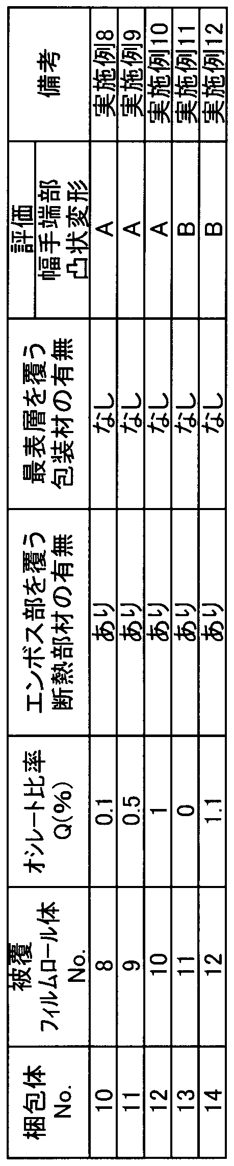
- each film roll is wound around the core by oscillating winding or straight winding so that the oscillating ratio Q defined by the above-described formula becomes the value shown in Table 3 for the optical film used in the production of the coated film roll body 1 Was made. Then, with respect to each film roll, the embossed portion and the side surface portion were covered with a heat insulating member in the same manner as in the production of the coated film roll body 1 to produce coated film roll bodies 8-12. As a result, the coated film roll bodies 8 to 12 are produced by the same production method as the above-described coated film roll bodies 3, 4, 5, 1, and 2, respectively.
- Packaging bodies 10 to 14 were produced in the same manner as the packaging body 1 except that the covering film roll body 1 was replaced with the covering film roll bodies 8 to 12, respectively.
- Table 3 shows the evaluation results for each of the coated film rolls 8-12. Table 3 also shows the correspondence between each of the coated film rolls 8 to 12 and the examples or comparative examples.
- Table 3 shows that when the oscillate ratio Q is larger than 1, weak convex deformation appears at the end. This is because when the amount of oscillate is increased, the contact area between the embossed portion of the lower film and the upper film is decreased, and the effect of preventing sticking by the embossed portion is decreased. As a result, the embossed portion is crushed in a short time, and the deformation of the base material that occurs when the air between the films escapes over time concentrates on the end portion, but the stress cannot be relaxed, and convex deformation tends to occur at the end portion. It is considered a thing.
- the oscillating rate Q is preferably greater than 0 and 1 or less.
- the optical film used in the production of the coated film roll body 1 was wound around a core by oscillating winding so that the oscillating ratio Q defined by the above-described formula was a value shown in Table 4 to produce a film roll. And after covering an embossed part and a side part with a heat insulation member by the same technique as preparation of covering film roll body 1 to this film roll, in a film roll, the outermost layer which is not covered with a heat insulation member is heat-insulated.
- the coated film roll body 13 was produced by covering with a packaging material having properties.
- the packaging material the same heat insulating sheet as the heat insulating member (manufactured by Kawakami Sangyo Co., Ltd., thickness 3.5 mm) was used.
- a packaging body 15 was produced in the same manner as the packaging body 1 except that the covering film roll body 1 was replaced with the covering film roll body 13.
- a coated film roll body 14 was produced in the same manner as the production of the coated film roll body 13 except that the outermost layer of the film roll was not coated with a packaging material having heat insulating properties. . As a result, the coated film roll body 14 is produced by the same production method as the above-described coated film roll body 4.
- a packaging body 16 was produced in the same manner as the packaging body 1 except that the covering film roll body 1 was replaced with the covering film roll body 14.
- Table 4 shows the results of evaluation for each of the coated film roll bodies 13 and 14. In addition, in Table 4, it also shows about the correspondence of each coating film roll body 13 * 14 and an Example or a comparative example.
- the coated film roll body 13 in which the outermost layer of the film roll is covered with a heat-insulating packaging material has a higher anti-sticking effect than the coated film roll body 14 in which the outermost layer is not covered with the packaging material. .
- a TAC film is used as an optical film constituting the film roll.
- an optical film is formed using a cellulose ester resin, a cycloolefin resin, a polyimide resin, a polyarylate resin, etc. other than TAC. Then, even when the optical film was wound to form a film roll and combined with a heat insulating member to produce a coated film roll body, it was confirmed that there was a tendency similar to that of the above-described example.
- coated film roll body of the present embodiment described above can be expressed as follows.
- a film roll which is a wound body in which a long optical film made of a thermoplastic resin is wound around a core;
- a heat insulating member having heat insulating properties and covering a part of the film roll;
- the optical film has a concavo-convex embossed portion at one or more places in the width direction along the core,
- the said heat insulation member is provided so that the side part which opposes in the said width direction through the outer peripheral surface of the said film roll, and the said embossing part of the said optical film may be covered.
- the width in the width direction of the optical film is W0 (mm)
- the shift width in the width direction due to oscillating winding between the laminated optical films is W1 (mm)
- packaging material according to any one of 1 to 3, further comprising a packaging material that has heat insulating properties and covers at least a part of the outermost layer of the film roll other than the embossed portion covered with the heat insulating member. Coated film roll body.
- the present invention can be used for a film roll package that is transported while being accommodated in a gantry.
Landscapes
- Engineering & Computer Science (AREA)
- Mechanical Engineering (AREA)
- Packages (AREA)
- Packaging Of Machine Parts And Wound Products (AREA)
- Laminated Bodies (AREA)
Abstract
Description
図1は、本実施形態のフィルムロールの梱包体(以下、単に梱包体とも称する)1の概略の構成を示す斜視図である。梱包体1は、被覆フィルムロール体2と、架台3と、被覆部材4とを備えている。なお、図1では、被覆部材4を明確にする目的で、被覆部材4にハッチングを付している(他の図面でも必要に応じてハッチングを付して示す)。図2は、被覆部材4で包装する前の被覆フィルムロール体2および架台3を示す斜視図である。なお、被覆フィルムロール体2の詳細については後述する。
次に、被覆フィルムロール体2の詳細について説明する。図4は、被覆フィルムロール体2に含まれるフィルムロール2’と、その被覆フィルムロール体2の斜視図である。被覆フィルムロール体2は、上記フィルムロール2’と、断熱部材2Pとを備えている。なお、図4では、断熱部材2Pを明確にする目的で、断熱部材2Pにハッチングを付している(他の図面でも必要に応じてハッチングを付して示す)。
0%<Q≦1.0%
であることが望ましい。ここで、オシレート比率Qとは、図6で示したように、光学フィルム10の幅手方向の幅をW0(mm)とし、積層される各光学フィルム10間でのオシレート巻きによる幅手方向のずれ幅をW1(mm)としたときに、以下の式で定義される比率を指す。
Q=(W1/W0)×100
図10は、被覆フィルムロール体2の他の構成を示す斜視図である。被覆フィルムロール体2は、包装材5をさらに備えていてもよい。包装材5は、断熱性を有し、断熱部材2Pで覆われたエンボス部11以外のフィルムロール2’の最表層2bの少なくとも一部を覆うシートであり、例えば、図7で示した気泡緩衝シート21や、不透明な金属シートまたは樹脂シートなど、断熱部材2Pを構成するシートと同様のシートで構成することができる。なお、上述した断熱部材2Pは、フィルムロール2’の一部(側面部2c、エンボス部11)しか覆わないため、最表層2bであってエンボス部11以外の部分を覆うように包装材5を設けることは十分に可能である。
図11は、梱包体1の他の構成を示す斜視図である。梱包体1において、被覆フィルムロール体2を収容する架台3を覆う被覆部材4は、断熱性を有する梱包材41と、透明シート42とを含んで構成されていてもよい。断熱性を有する梱包材41としては、上述した断熱部材2Pと同様の金属シート、樹脂シート、紙製シート、気泡緩衝シートなどを用いることができる。被覆部材4の一部が梱包材41で構成されることにより、外部の熱が梱包材41で遮断、吸収されるため、被覆フィルムロール体2ひいてはフィルムロール2’のエンボス部11への熱の伝達をより抑えることができ、エンボス部11の熱膨張をさらに抑えて、エンボス部の熱膨張に起因する地滑り状の故障および上下のフィルムの貼り付きをより抑えることができる。
上述した架台3において、下枠部31bは、金属板と一体化されて下面部を構成していてもよい。この場合、被覆部材4は、架台3の上記下面部を覆う必要が無く、上述した上面部4aおよび4つの側面部4cのみで構成することができる。このことから、被覆部材4は、架台3の少なくとも一部を覆うことによって、フィルムロール2を最表層2bと非接触で覆う構成であればよいと言える。
以下、本発明の具体的な実施例について説明する。なお、本発明はこれらの実施例に限定されるわけではない。
まず、幅手方向の両端にエンボスが形成された長尺状の光学フィルムであるセルローストリアセテートフィルムを(TACフィルム、幅1300mm、膜厚40μm)、ストレート巻きによって巻芯に巻き取ったフィルムロールAを用意した。すなわち、上記フィルムロールAは、TACフィルムという1種の光学フィルムのみの巻回体である(巻長は4000m)。なお、ストレート巻きであるため、上述の式で定義されるオシレート比率Qは、0である。
上記で作製した被覆フィルムロール体1を、図2と同様の構造を有する架台に収容した(被覆フィルムロール体の巻芯を架台で支持した)。そして、被覆フィルムロール体1の鉛直上方、鉛直下方、側方を覆うように、かつ、フィルムロールAの最表層と被覆部材とが非接触となるように、架台を被覆部材で包装し、梱包体1を作製した。このとき、上記被覆部材としては、透明シートを用いた。
被覆フィルムロール体1の作製で用いた光学フィルムを、上述した式で定義されるオシレート比率Qが1.1となるように、オシレート巻きによって巻芯に巻き取ってフィルムロールBを作製した。そして、このフィルムロールBに対して、被覆フィルムロール体1の作製と同様の手法でエンボス部および側面部を断熱部材で被覆して、被覆フィルムロール体2を作製した。
被覆フィルムロール体1を被覆フィルムロール体2に置き換えた以外は、梱包体1の作製と同様にして、梱包体2を作製した。
被覆フィルムロール体1の作製で用いたフィルムロールAを、エンボス部および側面部を断熱部材で被覆せず、そのままの状態で架台に収容した以外は、梱包体1の作製と同様にして、梱包体3を作製した。
被覆フィルムロール体2の作製で用いたフィルムロールBを、エンボス部および側面部を断熱部材で被覆せず、そのままの状態で架台に収容した以外は、梱包体2の作製と同様にして、梱包体4を作製した。
(エンボス部の潰れやすさ)
作製した梱包体1~4を、25℃の室内で保管した後、直射日光の当たる30℃の屋外に搬出し、60分間放置した。その後、梱包体1・2に収容された被覆フィルムロール体1・2においては、エンボス部を覆っていた断熱部材を取り除き、ロール最表面(巻芯から最も離れたロール表面)のエンボス部の凹凸差(凹部と凸部との差)EB1(μm)を、デジタルマイクロメータ装置(ソニーマニュファクチュアリングシステムズ株式会社製、型番M-30)を用いて実測した。また、梱包体3・4に収容されたフィルムロールA・Bにおいては、ロール最表面のエンボス部の凹凸差EB1(μm)を、上記デジタルマイクロメータ装置を用いて実測した。
《評価基準》
A・・・凹凸差の減少率Eが15%以下である(エンボス部が潰れにくい)。
B・・・凹凸差の減少率Eが15%よりも大きい(エンボス部が潰れており、実害がある)。
上記のように梱包体1~4を屋外に放置後、各ロールからフィルムを同一張力で巻芯部まで繰り出すときに、巻芯方向(幅手方向)に地滑りした量を、定規を用いて計測した。そして、フィルムの幅手方向の長さWA(mm)とし、幅手方向の地滑り量(変位)をWB(mm)として、地滑り率h(%)を、h={(WA-WB)/WA}×100により算出し、以下の評価基準に基づいて、地滑り性について評価した。
《評価基準》
A・・・h≦2%であり、地滑りがほとんど発生していない。
B・・・h>2%であり、地滑りが発生している。

被覆フィルムロール体1の作製で用いた光学フィルムを、上述した式で定義されるオシレート比率Qが表2に示す値となるように、オシレート巻きまたはストレート巻きによって巻芯に巻き取って各フィルムロールを作製した。そして、各フィルムロールに対して、被覆フィルムロール体1の作製と同様の手法でエンボス部および側面部を断熱部材で被覆して、被覆フィルムロール体3~7を作製した。なお、結果的には、被覆フィルムロール体6は、被覆フィルムロール体2と同様の作製方法によって作製され、被覆フィルムロール体7は、被覆フィルムロール体1と同様の作製方法によって作製される。
被覆フィルムロール体1を被覆フィルムロール体3~7にそれぞれ置き換えた以外は、梱包体1の作製と同様にして、梱包体5~9をそれぞれ作製した。
(貼り付き性)
作製した梱包体5~9を、25℃の室内で保管した後、直射日光の当たる30℃の屋外に搬出し、60分間放置した。その後、梱包体5~9に収容された被覆フィルムロール体3~7からフィルムを繰り出して、幅手方向において(例えば幅手中央部において)フィルムの貼り付きがあるかどうかを目視で確認した。そして、以下の評価基準に基づいて、貼り付き性について評価した。
《評価基準》
A・・・貼り付きがほとんど確認されなかった。
B・・・弱い貼り付きが確認されたが、弾性変形に留まっており、問題はない。
C・・・強い貼り付きが確認され、塑性変形になっている。

被覆フィルムロール体1の作製で用いた光学フィルムを、上述した式で定義されるオシレート比率Qが表3に示す値となるように、オシレート巻きまたはストレート巻きによって巻芯に巻き取って各フィルムロールを作製した。そして、各フィルムロールに対して、被覆フィルムロール体1の作製と同様の手法でエンボス部および側面部を断熱部材で被覆して、被覆フィルムロール体8~12を作製した。なお、結果的には、被覆フィルムロール体8~12は、それぞれ、上述した被覆フィルムロール体3、4、5、1、2と同様の作製方法によって作製される。
被覆フィルムロール体1を被覆フィルムロール体8~12にそれぞれ置き換えた以外は、梱包体1の作製と同様にして、梱包体10~14をそれぞれ作製した。
(端部凸状変形)
作製した梱包体10~14を、25℃の室内で保管した後、直射日光の当たる30℃の屋外に搬出し、60分間放置した。その後、梱包体10~14に収容された被覆フィルムロール体8~12からフィルムを繰り出して、幅手方向の端部(断熱部材によるエンボス部の被覆箇所を除く)において、凸状変形の有無を目視で確認した。なお、この端部の凸状変形は、貼り付き(ブロッキング)の一種であり、異物を挟んだような凸状の変形で、幅手端部に生じやすい現象である。そして、以下の評価基準に基づいて、凸状変形について評価した。
《評価基準》
A・・・凸状変形が全く確認されなかった。
B・・・弱い凸状変形が確認されたが、実害はない。
C・・・強い凸状変形が確認され、塑性変形になっている。
被覆フィルムロール体1の作製で用いた光学フィルムを、上述した式で定義されるオシレート比率Qが表4に示す値となるように、オシレート巻きによって巻芯に巻き取ってフィルムロールを作製した。そして、このフィルムロールに対して、被覆フィルムロール体1の作製と同様の手法でエンボス部および側面部を断熱部材で被覆した後、フィルムロールにおいて、断熱部材で被覆されていない最表層を、断熱性を有する包装材で被覆して、被覆フィルムロール体13を作製した。なお、上記包装材としては、上記断熱部材と同一の断熱シート(川上産業株式会社製、厚み3.5mm)を用いた。
被覆フィルムロール体1を被覆フィルムロール体13に置き換えた以外は、梱包体1の作製と同様にして、梱包体15を作製した。
被覆フィルムロール体13の作製において、フィルムロールの最表層を、断熱性を有する包装材で被覆しなかった以外は、被覆フィルムロール体13の作製と同様にして、被覆フィルムロール体14を作製した。なお、結果的には、被覆フィルムロール体14は、上述した被覆フィルムロール体4と同様の作製方法によって作製される。
被覆フィルムロール体1を被覆フィルムロール体14に置き換えた以外は、梱包体1の作製と同様にして、梱包体16を作製した。
(貼り付き性)
作製した梱包体15・16を、25℃の室内で保管した後、直射日光の当たる30℃の屋外に搬出し、60分間放置した。その後、梱包体15・16に収容された被覆フィルムロール体13・14からフィルムを繰り出して、幅手方向において(例えば幅手中央部において)フィルムの貼り付きがあるかどうかを目視で確認した。そして、以下の評価基準に基づいて、貼り付き性について評価した。
《評価基準》
AA・・・貼り付きが全く確認されなかった。
A ・・・貼り付きがほとんど確認されなかった。
B ・・・弱い貼り付きが確認されたが、弾性変形に留まっており、問題はない。
C ・・・強い貼り付きが確認され、塑性変形になっている。

以上、本発明の実施形態につき説明したが、本発明の範囲はこれに限定されるものではなく、発明の主旨を逸脱しない範囲で種々の変更を加えて実施することができる。
断熱性を有し、前記フィルムロールの一部を覆う断熱部材とを備え、
前記光学フィルムは、前記巻芯に沿う幅手方向の1か所以上に凹凸状のエンボス部を有しており、
前記断熱部材は、前記フィルムロールの外周面を介して前記幅手方向において対向する側面部と、前記光学フィルムの前記エンボス部とを覆うように設けられていることを特徴とする被覆フィルムロール体。
Q=(W1/W0)×100
で定義したとき、
0%<Q≦1.0%
であることを特徴とする前記2に記載の被覆フィルムロール体。
2’ フィルムロール
2a 軸芯
2b 最表層
2b1 外周面
2c 側面部
2P 断熱部材
5 包装材
10 光学フィルム
11 エンボス部
Claims (4)
- 熱可塑性樹脂からなる長尺状の光学フィルムを巻芯の周りに巻回した巻回体であるフィルムロールと、
断熱性を有し、前記フィルムロールの一部を覆う断熱部材とを備え、
前記光学フィルムは、前記巻芯に沿う幅手方向の1か所以上に凹凸状のエンボス部を有しており、
前記断熱部材は、前記フィルムロールの外周面を介して前記幅手方向において対向する側面部と、前記光学フィルムの前記エンボス部とを覆うように設けられている、被覆フィルムロール体。 - 前記フィルムロールは、前記光学フィルムのオシレート巻きによる巻回体である、請求項1に記載の被覆フィルムロール体。
- 前記光学フィルムの前記幅手方向の幅をW0(mm)とし、積層される各光学フィルム間でのオシレート巻きによる前記幅手方向のずれ幅をW1(mm)とし、オシレート比率Q(%)を、
Q=(W1/W0)×100
で定義したとき、
0%<Q≦1.0%
である、請求項2に記載の被覆フィルムロール体。 - 断熱性を有し、前記断熱部材で覆われた前記エンボス部以外の前記フィルムロールの最表層の少なくとも一部を覆う包装材を備えている、請求項1から3のいずれかに記載の被覆フィルムロール体。
Priority Applications (3)
| Application Number | Priority Date | Filing Date | Title |
|---|---|---|---|
| JP2018553699A JP7159869B2 (ja) | 2016-12-01 | 2017-10-12 | 被覆フィルムロール体 |
| CN201780073493.3A CN110023207A (zh) | 2016-12-01 | 2017-10-12 | 覆盖膜卷体 |
| KR1020197015329A KR102183525B1 (ko) | 2016-12-01 | 2017-10-12 | 피복 필름 롤체 |
Applications Claiming Priority (2)
| Application Number | Priority Date | Filing Date | Title |
|---|---|---|---|
| JP2016233980 | 2016-12-01 | ||
| JP2016-233980 | 2016-12-01 |
Publications (1)
| Publication Number | Publication Date |
|---|---|
| WO2018100896A1 true WO2018100896A1 (ja) | 2018-06-07 |
Family
ID=62242477
Family Applications (1)
| Application Number | Title | Priority Date | Filing Date |
|---|---|---|---|
| PCT/JP2017/036931 Ceased WO2018100896A1 (ja) | 2016-12-01 | 2017-10-12 | 被覆フィルムロール体 |
Country Status (4)
| Country | Link |
|---|---|
| JP (1) | JP7159869B2 (ja) |
| KR (1) | KR102183525B1 (ja) |
| CN (1) | CN110023207A (ja) |
| WO (1) | WO2018100896A1 (ja) |
Cited By (2)
| Publication number | Priority date | Publication date | Assignee | Title |
|---|---|---|---|---|
| JP2022036728A (ja) * | 2020-08-24 | 2022-03-08 | 日東電工株式会社 | フィルムロール梱包体およびその製造方法、ならびにロール体の保管方法 |
| JP2022039752A (ja) * | 2020-08-28 | 2022-03-10 | キョーラク株式会社 | フィルムロール、内容物の充填方法 |
Citations (8)
| Publication number | Priority date | Publication date | Assignee | Title |
|---|---|---|---|---|
| US3737028A (en) * | 1971-04-08 | 1973-06-05 | Morgan Adhesives Co | Packaged adhesive laminate and method of making the same |
| GB2271754A (en) * | 1992-10-24 | 1994-04-27 | Ilford Anitec N V | Light tight packaging of rolled web of light-sensitive material |
| JPH08292523A (ja) * | 1995-04-18 | 1996-11-05 | Agfa Gevaert Nv | 光線を通さないように包装されたロール |
| JP2010179922A (ja) * | 2009-02-03 | 2010-08-19 | Konica Minolta Opto Inc | フィルムロール包装体及びフィルムロール包装体形成方法 |
| JP2010221625A (ja) * | 2009-03-25 | 2010-10-07 | Nippon Zeon Co Ltd | ロール状巻回体 |
| JP2011154256A (ja) * | 2010-01-28 | 2011-08-11 | Sumitomo Chemical Co Ltd | 光学フィルムの梱包保管方法 |
| WO2014132625A1 (ja) * | 2013-02-27 | 2014-09-04 | コニカミノルタ株式会社 | 光学フィルムロールの製造方法 |
| JP2016014869A (ja) * | 2014-06-13 | 2016-01-28 | コニカミノルタ株式会社 | 環状ポリオレフィンフィルムの製造方法及び環状ポリオレフィンフィルム |
Family Cites Families (2)
| Publication number | Priority date | Publication date | Assignee | Title |
|---|---|---|---|---|
| JP3478667B2 (ja) * | 1996-05-30 | 2003-12-15 | 帝人株式会社 | 写真フィルム用ベースフィルム |
| JP5402958B2 (ja) * | 2011-02-16 | 2014-01-29 | コニカミノルタ株式会社 | セルロースアシレートフィルムの製造方法 |
-
2017
- 2017-10-12 CN CN201780073493.3A patent/CN110023207A/zh active Pending
- 2017-10-12 KR KR1020197015329A patent/KR102183525B1/ko active Active
- 2017-10-12 WO PCT/JP2017/036931 patent/WO2018100896A1/ja not_active Ceased
- 2017-10-12 JP JP2018553699A patent/JP7159869B2/ja active Active
Patent Citations (8)
| Publication number | Priority date | Publication date | Assignee | Title |
|---|---|---|---|---|
| US3737028A (en) * | 1971-04-08 | 1973-06-05 | Morgan Adhesives Co | Packaged adhesive laminate and method of making the same |
| GB2271754A (en) * | 1992-10-24 | 1994-04-27 | Ilford Anitec N V | Light tight packaging of rolled web of light-sensitive material |
| JPH08292523A (ja) * | 1995-04-18 | 1996-11-05 | Agfa Gevaert Nv | 光線を通さないように包装されたロール |
| JP2010179922A (ja) * | 2009-02-03 | 2010-08-19 | Konica Minolta Opto Inc | フィルムロール包装体及びフィルムロール包装体形成方法 |
| JP2010221625A (ja) * | 2009-03-25 | 2010-10-07 | Nippon Zeon Co Ltd | ロール状巻回体 |
| JP2011154256A (ja) * | 2010-01-28 | 2011-08-11 | Sumitomo Chemical Co Ltd | 光学フィルムの梱包保管方法 |
| WO2014132625A1 (ja) * | 2013-02-27 | 2014-09-04 | コニカミノルタ株式会社 | 光学フィルムロールの製造方法 |
| JP2016014869A (ja) * | 2014-06-13 | 2016-01-28 | コニカミノルタ株式会社 | 環状ポリオレフィンフィルムの製造方法及び環状ポリオレフィンフィルム |
Cited By (3)
| Publication number | Priority date | Publication date | Assignee | Title |
|---|---|---|---|---|
| JP2022036728A (ja) * | 2020-08-24 | 2022-03-08 | 日東電工株式会社 | フィルムロール梱包体およびその製造方法、ならびにロール体の保管方法 |
| JP2022039752A (ja) * | 2020-08-28 | 2022-03-10 | キョーラク株式会社 | フィルムロール、内容物の充填方法 |
| JP7492132B2 (ja) | 2020-08-28 | 2024-05-29 | キョーラク株式会社 | フィルムロール、内容物の充填方法 |
Also Published As
| Publication number | Publication date |
|---|---|
| KR102183525B1 (ko) | 2020-11-26 |
| JPWO2018100896A1 (ja) | 2019-10-17 |
| JP7159869B2 (ja) | 2022-10-25 |
| KR20190076019A (ko) | 2019-07-01 |
| CN110023207A (zh) | 2019-07-16 |
Similar Documents
| Publication | Publication Date | Title |
|---|---|---|
| JP5930485B2 (ja) | ガラスシートを梱包するパッケージおよび梱包方法 | |
| JP4562795B2 (ja) | ロール原反及びロール原反製造方法 | |
| JP6246874B2 (ja) | ポリビニルアルコールフィルムロールの包装体 | |
| WO2012026327A1 (ja) | 光学機能フィルム連続ロール、およびそれを用いた液晶表示素子の製造方法、ならびに光学機能フィルム貼り合せ装置 | |
| KR20130112875A (ko) | 광학 기능 필름 연속 롤 및 그것을 사용한 액정 표시 소자의 제조 방법, 및 광학 기능 필름 접합 장치 | |
| TW201733938A (zh) | 玻璃卷及其製造方法 | |
| WO2018100896A1 (ja) | 被覆フィルムロール体 | |
| JP6962333B2 (ja) | フィルムロールの梱包体 | |
| JP2011232625A (ja) | ロール原反および液晶パネルの製造方法 | |
| JP5130174B2 (ja) | 光学フィルム巻取り原反及びその製造方法 | |
| JPWO2012060142A1 (ja) | フィルムロールの包装体、およびその製造方法 | |
| CN112455928A (zh) | 包装体、聚乙烯醇系薄膜的保管或运输方法、聚乙烯醇系薄膜、及偏光膜 | |
| TWI901748B (zh) | 膜捲筒捆包體及其製造方法、以及輥體之保管方法 | |
| JP4359321B2 (ja) | ロールフィルム端部保護具 | |
| JP4399523B2 (ja) | 積層偏光フィルムの製造方法 | |
| JP7217115B2 (ja) | 多孔質材の梱包体及び多孔質材の梱包体の製造方法 | |
| JP2018146735A (ja) | 光学フィルム、原反ロール、および光学部材シートの製造方法 | |
| CN101343005A (zh) | 置料木护架及其护板的改进结构 | |
| JP2015081165A (ja) | フィルムロールの皺対策構造 | |
| JP2018008733A (ja) | 包装体、その製造方法、及び、包装方法 |
Legal Events
| Date | Code | Title | Description |
|---|---|---|---|
| 121 | Ep: the epo has been informed by wipo that ep was designated in this application |
Ref document number: 17877233 Country of ref document: EP Kind code of ref document: A1 |
|
| ENP | Entry into the national phase |
Ref document number: 2018553699 Country of ref document: JP Kind code of ref document: A |
|
| ENP | Entry into the national phase |
Ref document number: 20197015329 Country of ref document: KR Kind code of ref document: A |
|
| NENP | Non-entry into the national phase |
Ref country code: DE |
|
| 122 | Ep: pct application non-entry in european phase |
Ref document number: 17877233 Country of ref document: EP Kind code of ref document: A1 |