WO2018100798A1 - 密閉型二次電池の変形検出センサ、密閉型二次電池、及び密閉型二次電池の変形検出方法 - Google Patents
密閉型二次電池の変形検出センサ、密閉型二次電池、及び密閉型二次電池の変形検出方法 Download PDFInfo
- Publication number
- WO2018100798A1 WO2018100798A1 PCT/JP2017/027240 JP2017027240W WO2018100798A1 WO 2018100798 A1 WO2018100798 A1 WO 2018100798A1 JP 2017027240 W JP2017027240 W JP 2017027240W WO 2018100798 A1 WO2018100798 A1 WO 2018100798A1
- Authority
- WO
- WIPO (PCT)
- Prior art keywords
- secondary battery
- sealed secondary
- magnetic filler
- coupling agent
- detection sensor
- Prior art date
- Legal status (The legal status is an assumption and is not a legal conclusion. Google has not performed a legal analysis and makes no representation as to the accuracy of the status listed.)
- Ceased
Links
Images
Classifications
-
- H—ELECTRICITY
- H01—ELECTRIC ELEMENTS
- H01M—PROCESSES OR MEANS, e.g. BATTERIES, FOR THE DIRECT CONVERSION OF CHEMICAL ENERGY INTO ELECTRICAL ENERGY
- H01M10/00—Secondary cells; Manufacture thereof
- H01M10/42—Methods or arrangements for servicing or maintenance of secondary cells or secondary half-cells
- H01M10/48—Accumulators combined with arrangements for measuring, testing or indicating the condition of cells, e.g. the level or density of the electrolyte
-
- G—PHYSICS
- G01—MEASURING; TESTING
- G01B—MEASURING LENGTH, THICKNESS OR SIMILAR LINEAR DIMENSIONS; MEASURING ANGLES; MEASURING AREAS; MEASURING IRREGULARITIES OF SURFACES OR CONTOURS
- G01B7/00—Measuring arrangements characterised by the use of electric or magnetic techniques
- G01B7/16—Measuring arrangements characterised by the use of electric or magnetic techniques for measuring the deformation in a solid, e.g. by resistance strain gauge
- G01B7/24—Measuring arrangements characterised by the use of electric or magnetic techniques for measuring the deformation in a solid, e.g. by resistance strain gauge using change in magnetic properties
-
- H—ELECTRICITY
- H01—ELECTRIC ELEMENTS
- H01M—PROCESSES OR MEANS, e.g. BATTERIES, FOR THE DIRECT CONVERSION OF CHEMICAL ENERGY INTO ELECTRICAL ENERGY
- H01M50/00—Constructional details or processes of manufacture of the non-active parts of electrochemical cells other than fuel cells, e.g. hybrid cells
- H01M50/20—Mountings; Secondary casings or frames; Racks, modules or packs; Suspension devices; Shock absorbers; Transport or carrying devices; Holders
- H01M50/204—Racks, modules or packs for multiple batteries or multiple cells
- H01M50/207—Racks, modules or packs for multiple batteries or multiple cells characterised by their shape
- H01M50/209—Racks, modules or packs for multiple batteries or multiple cells characterised by their shape adapted for prismatic or rectangular cells
-
- H—ELECTRICITY
- H01—ELECTRIC ELEMENTS
- H01M—PROCESSES OR MEANS, e.g. BATTERIES, FOR THE DIRECT CONVERSION OF CHEMICAL ENERGY INTO ELECTRICAL ENERGY
- H01M50/00—Constructional details or processes of manufacture of the non-active parts of electrochemical cells other than fuel cells, e.g. hybrid cells
- H01M50/20—Mountings; Secondary casings or frames; Racks, modules or packs; Suspension devices; Shock absorbers; Transport or carrying devices; Holders
- H01M50/204—Racks, modules or packs for multiple batteries or multiple cells
- H01M50/207—Racks, modules or packs for multiple batteries or multiple cells characterised by their shape
- H01M50/211—Racks, modules or packs for multiple batteries or multiple cells characterised by their shape adapted for pouch cells
-
- H—ELECTRICITY
- H01—ELECTRIC ELEMENTS
- H01M—PROCESSES OR MEANS, e.g. BATTERIES, FOR THE DIRECT CONVERSION OF CHEMICAL ENERGY INTO ELECTRICAL ENERGY
- H01M50/00—Constructional details or processes of manufacture of the non-active parts of electrochemical cells other than fuel cells, e.g. hybrid cells
- H01M50/20—Mountings; Secondary casings or frames; Racks, modules or packs; Suspension devices; Shock absorbers; Transport or carrying devices; Holders
- H01M50/204—Racks, modules or packs for multiple batteries or multiple cells
- H01M50/207—Racks, modules or packs for multiple batteries or multiple cells characterised by their shape
- H01M50/213—Racks, modules or packs for multiple batteries or multiple cells characterised by their shape adapted for cells having curved cross-section, e.g. round or elliptic
-
- Y—GENERAL TAGGING OF NEW TECHNOLOGICAL DEVELOPMENTS; GENERAL TAGGING OF CROSS-SECTIONAL TECHNOLOGIES SPANNING OVER SEVERAL SECTIONS OF THE IPC; TECHNICAL SUBJECTS COVERED BY FORMER USPC CROSS-REFERENCE ART COLLECTIONS [XRACs] AND DIGESTS
- Y02—TECHNOLOGIES OR APPLICATIONS FOR MITIGATION OR ADAPTATION AGAINST CLIMATE CHANGE
- Y02E—REDUCTION OF GREENHOUSE GAS [GHG] EMISSIONS, RELATED TO ENERGY GENERATION, TRANSMISSION OR DISTRIBUTION
- Y02E60/00—Enabling technologies; Technologies with a potential or indirect contribution to GHG emissions mitigation
- Y02E60/10—Energy storage using batteries
Definitions
- the present invention relates to a sensor for detecting deformation of a sealed secondary battery, a sealed secondary battery to which the sensor is attached, and a method for detecting deformation of the sealed secondary battery.
- sealed secondary batteries represented by lithium ion secondary batteries (hereinafter also simply referred to as “secondary batteries”) are not only mobile devices such as mobile phones and laptop computers but also electric vehicles such as electric vehicles and hybrid vehicles. It is also used as a power source for vehicles.
- a single battery (cell) that constitutes a secondary battery includes an electrode group in which a positive electrode and a negative electrode are wound or stacked with a separator interposed therebetween, and an outer package that houses the electrode group.
- a laminate film or a metal can is used as an exterior body, and an electrode group is accommodated together with an electrolytic solution in an enclosed space.
- Secondary batteries are used in the form of battery modules or battery packs that include a plurality of single cells in applications where a high voltage is required, such as the power supply for electric vehicles described above.
- a battery module a plurality of single cells connected in series are accommodated in a housing, and for example, four single cells are connected in two parallel two series or four series.
- various devices such as a controller are accommodated in the casing in addition to the plurality of battery modules connected in series.
- a battery pack housing is formed in a shape suitable for in-vehicle use.
- Such a secondary battery has a problem that when the electrolytic solution is decomposed due to overcharge or the like, the unit cell expands as the internal pressure increases due to the decomposition gas, and the secondary battery is deformed. In that case, if the charging current or discharging current is not stopped, it will ignite and the secondary battery will burst as the worst result. Therefore, in order to prevent the secondary battery from bursting, it is important to detect the deformation of the secondary battery due to the swelling of the single cell with high sensitivity so that the charging current and the discharging current can be stopped in a timely manner.
- Patent Document 1 includes a polymer matrix layer and a detection unit, and the polymer matrix layer includes a filler that changes the external field according to deformation of the polymer matrix layer.
- a deformation detection sensor for a sealed secondary battery that is contained in a dispersed manner and in which the detection unit detects a change in the external field.
- the deformation detection sensor detects a change in the magnetic matrix accompanying the deformation of the polymer matrix layer when the deformation of the secondary battery due to the swelling of the single cell causes the deformation of the polymer matrix layer containing the magnetic filler.
- the deformation of the secondary battery is detected by the detecting unit.
- the present invention provides a deformation detection sensor for a sealed secondary battery having higher sensitivity and excellent stability, a sealed secondary battery to which the sensor is attached, and a deformation detection method for the sealed secondary battery.
- the deformation detection sensor of the sealed secondary battery of the present invention includes a polymer matrix layer and a detection unit, and the polymer matrix layer includes a polymer, a magnetic filler, and a coupling agent, The polymer forms a matrix of the polymer matrix layer, the magnetic filler changes the magnetic field according to the deformation of the polymer matrix layer, and the detection unit detects the change of the magnetic field.
- the sealed secondary battery of the present invention is characterized in that the deformation detection sensor is attached.
- the deformation detection method for a sealed secondary battery according to the present invention is characterized by using the deformation detection sensor.
- the present invention it is possible to provide a deformation detection sensor for a sealed secondary battery, a sealed secondary battery, and a deformation detection method for the sealed secondary battery, which are more sensitive and excellent in stability.
- the reason why the deformation detection sensor of the sealed secondary battery of the present invention has such an effect is not clear, but is considered as follows.
- the sensitivity and stability of conventional deformation detection sensors are relatively low because the adhesion between the polymer and the magnetic filler is not sufficient, and the energy due to friction at the interface between the polymer and the magnetic filler when the polymer matrix layer is deformed. It is thought that the cause is that loss occurs or the followability of the magnetic filler is low.
- the deformation detection sensor of the present invention is considered to improve the stability of the sensor by reducing the energy loss due to friction at the interface by improving the adhesion between the polymer and the magnetic filler as a matrix by the coupling agent. .
- the sensor sensitivity is improved because the magnetic filler can easily follow the deformation of the polymer matrix layer.
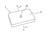
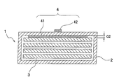
- FIG. 1 A perspective view schematically showing an example of a battery module Sectional drawing which shows typically the AA arrow cross section of FIG. Sectional drawing which shows another example of the attachment location of a polymer matrix layer
- FIG. 1 is a perspective view of a battery module 1 having a deformation detection sensor (hereinafter, also simply referred to as “deformation detection sensor”) of a sealed secondary battery
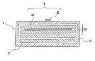
- FIG. 2 is a perspective view of the battery module 1 of FIG. It is A arrow sectional drawing.
- the battery module 1 includes a housing 2, a single battery 3, and a deformation detection sensor 4.
- the unit cell 3 is inside the housing 2, and the deformation detection sensor 4 is attached to the unit cell 3.
- the deformation detection sensor 4 includes a polymer matrix layer 41 and a detection unit 42.
- the polymer matrix layer 41 includes a polymer, a magnetic filler, and a coupling agent. The matrix of the polymer matrix layer 41 is formed, the magnetic filler changes the magnetic field according to the deformation of the polymer matrix layer 41, and the detection unit 42 detects the change of the magnetic field.
- the battery module 1 is, for example, a lithium ion secondary battery that can be used as a power source for an electric vehicle, and is mounted on the vehicle in the form of a battery pack.
- the plurality of battery modules 1 connected in series are housed in a casing together with various devices such as a controller.
- the casing 2 of the battery pack is formed in a shape suitable for in-vehicle use, for example, a shape that matches the underfloor shape of the vehicle.
- the sealed secondary battery 3 is not limited to a non-aqueous electrolyte secondary battery such as a lithium ion battery, and may be an aqueous electrolyte secondary battery such as a nickel metal hydride battery.
- the unit cell 3 includes an electrode group formed by winding or laminating a positive electrode and a negative electrode with a separator between them, and an exterior body that accommodates the electrode group, and in an enclosed space inside the exterior body The electrode group is accommodated together with the electrolyte (not shown).
- a laminate film such as an aluminum laminate foil is used for the outer package of the unit cell 3, but a cylindrical or square metal can may be used instead.
- the polymer matrix layer 41 is affixed to the surface of the unit cell 3 (the outer surface of the exterior body), and an adhesive or an adhesive tape is used for the affixation as necessary.
- the polymer matrix layer 41 is formed in a sheet shape, and is formed in a gap in the secondary battery, for example, in a gap between the adjacent single cells 3 or as shown in FIG. It is arranged between the body 2.
- the polymer matrix layer 41 may be bent and attached to the corners of the unit cell 3 or the housing 2.
- the polymer matrix layer 41 contains the magnetic filler that changes the magnetic field in accordance with the deformation of the polymer matrix layer 41.
- the detection unit 42 detects a change in the magnetic field.
- the detection unit 42 is disposed away from the polymer matrix layer 41 to such an extent that a change in magnetic field can be detected, and is preferably affixed to a relatively firm location that is not easily affected by the swelling of the unit cell 3.
- the detection unit 42 is attached to the outer surface of the housing 2, but the present invention is not limited to this, and the detection unit 42 may be attached to the inner surface of the housing 2 or the battery pack housing. I do not care.
- These cases are formed of, for example, metal or plastic, and a laminate film may be used for the case of the battery module.
- the polymer matrix layer 41 is preferably mounted in a compressed state while being sandwiched in the gap of the deformation detection sensor 4.
- the thickness of the polymer matrix layer 41 in an uncompressed state is larger than the gap G1 in which the polymer matrix layer 41 is disposed, and the polymer matrix layer 41 is compressed in the thickness direction.
- the polymer matrix layer 41 shown in FIG. 3 is also sandwiched and mounted in the gap. In this example, the polymer matrix layer 41 is sandwiched and mounted in the gap between the unit cell 3 and the housing 2.
- the thickness of the polymer matrix layer 41 in an uncompressed state is larger than the gap G2 in which the polymer matrix layer 41 is disposed, and the polymer matrix layer 41 is also preferably compressed in the thickness direction.
- the thickness of the polymer matrix layer 41 in an uncompressed state is preferably 50 to 4000 ⁇ m, more preferably 100 to 3000 ⁇ m, and still more preferably 300 to 2500 ⁇ m.
- the thickness is smaller than 50 ⁇ m, when an attempt is made to add the required amount of the magnetic filler, it tends to become brittle and the handling property tends to deteriorate.
- the thickness is larger than 4000 ⁇ m, the polymer matrix layer 41 is excessively compressed and hardly deformed when disposed in the gap as described above, and the sensor sensitivity may be lowered.
- the detection unit 42 When the unit cell 3 swells, the polymer matrix layer 41 is deformed accordingly, and a change in the magnetic field accompanying the deformation of the polymer matrix layer 41 is detected by the detection unit 42.
- the detection signal output from the detection unit 42 is sent to a control device (not shown).
- the detection signal connected to the control device (not shown) is connected.
- the switching circuit cuts off the energization and stops the charging current or discharging current. In this way, deformation of the unit cell 3 is detected with high sensitivity, and explosion is prevented in advance.
- the deformation detection sensor 4 does not press the unit cell 3 and the positional deviation is suppressed, so that the sensor characteristics are stabilized.
- one polymer matrix layer 41 and one detection unit 42 are shown, but a plurality of them may be used depending on various conditions such as the shape and size of the unit cell 3. Good. At that time, the polymer matrix layer 41 attached as shown in FIG. 2 and the polymer matrix layer 41 attached as shown in FIG. 3 may coexist. Further, a plurality of polymer matrix layers 41 may be attached to the same unit cell 3, or a plurality of detectors 42 may be configured to detect changes in the external field due to deformation of the same polymer matrix layer 41. Good.
- an elastomer component can be used, and the elastomer component can be arbitrarily used.
- a thermoplastic elastomer, a thermosetting elastomer, or a mixture thereof can be used.
- thermoplastic elastomer examples include styrene-based thermoplastic elastomer, polyolefin-based thermoplastic elastomer, polyurethane-based thermoplastic elastomer, polyester-based thermoplastic elastomer, polyamide-based thermoplastic elastomer, polybutadiene-based thermoplastic elastomer, polyisoprene-based thermoplastic elastomer, A fluororubber-based thermoplastic elastomer can be used.
- thermosetting elastomer examples include polyisoprene rubber, polybutadiene rubber, styrene-butadiene rubber, polychloroprene rubber, nitrile rubber, diene synthetic rubber such as ethylene-propylene rubber, ethylene-propylene rubber, butyl rubber, acrylic rubber, Non-diene synthetic rubbers such as polyurethane rubber, fluorine rubber, silicone rubber, epichlorohydrin rubber, and natural rubber can be mentioned.
- a thermosetting elastomer is preferable because it can suppress the sag of the magnetic elastomer accompanying heat generation and overload of the battery. More preferred is polyurethane rubber (also referred to as polyurethane elastomer) or silicone rubber (also referred to as silicone elastomer).
- the polyurethane elastomer is obtained by reacting an active hydrogen-containing compound with an isocyanate component.
- an active hydrogen-containing compound and a magnetic filler are mixed, and an isocyanate component is mixed therein to obtain a mixed solution.
- a liquid mixture can also be obtained by mixing a magnetic filler with an isocyanate component and mixing an active hydrogen-containing compound. The mixed liquid is poured into a mold subjected to a release treatment, and then heated to a curing temperature and cured to produce a magnetic elastomer.
- a magnetic elastomer can be produced by adding a magnetic filler to a silicone elastomer precursor, mixing it, putting it in a mold, and then heating and curing it. In addition, you may add a solvent as needed.
- isocyanate component that can be used in the polyurethane elastomer
- compounds known in the field of polyurethane can be used.
- the isocyanate component may be modified such as urethane modification, allophanate modification, biuret modification, and isocyanurate modification.
- Preferred isocyanate components are 2,4-toluene diisocyanate, 2,6-toluene diisocyanate, 4,4'-diphenylmethane disissocyanate, more preferably 2,4-toluene diisocyanate, 2,6-toluene diisocyanate.
- polyurethane those usually used in the technical field of polyurethane can be used.
- Polyester polyol such as polyester polyol, polycaprolactone polyol, reaction product of polyester glycol and alkylene carbonate such as polycaprolactone, and the like, and the reaction of the resulting reaction mixture with organic polyol.
- Polyester polycarbonate polyol reacted with dicarboxylic acid, esterification of polyhydroxyl compound and aryl carbonate High molecular weight polyol polycarbonate polyols obtained by the reaction can be mentioned. These may be used alone or in combination of two or more.
- ethylene glycol 1,2-propylene glycol, 1,3-propylene glycol, 1,4-butanediol, 1,6-hexanediol, neopentyl glycol 1,4-cyclohexanedimethanol, 3-methyl-1,5-pentanediol, diethylene glycol, triethylene glycol, 1,4-bis (2-hydroxyethoxy) benzene, trimethylolpropane, glycerin, 1,2,6 -Hexanetriol, pentaerythritol, tetramethylolcyclohexane, methylglucoside, sorbitol, mannitol, dulcitol, sucrose, 2,2,6,6-tetrakis (hydroxymethyl) cyclohexanol, and triethanol
- Low molecular weight polyol component such as an amine, ethylenediamine
- Preferred active hydrogen-containing compounds are polytetramethylene glycol, polypropylene glycol, a copolymer of propylene oxide and ethylene oxide, 3-methyl-1,5-pentane adipate, more preferably a copolymer of polypropylene glycol, propylene oxide and ethylene oxide. It is a coalescence.
- a known catalyst that promotes the polyurethane reaction such as a tertiary amine catalyst or a metal catalyst may be used.
- the tertiary amine include triethylenediamine (1,4-diazabicyclo [2,2,2] octane), N, N, N ′, N′-tetramethylhexanediamine, and bis (2-dimethylaminoethyl) ether. Etc. can be illustrated.
- the metal catalyst include tin octylate, lead octylate, zinc octylate, bismuth octylate, and the like. These may be used alone or in combination of two or more.
- the NCO index is preferably 0.3 to 1.2, more preferably 0.5 to 1.1, and still more preferably 0.7 to 1.05.
- the NCO index is less than 0.3, the polyurethane tends to be insufficiently cured.
- the NCO index is greater than 1.2, the elastic modulus increases and the sensor sensitivity tends to decrease.
- the silicone elastomer to be used is not particularly limited, but a two-component heating type addition reaction type silicone elastomer is preferable from the viewpoint of dispersing the magnetic filler.
- silicone elastomers KE-1204, KE-1031, KE-106, KE-109, KE-1281 (above, manufactured by Shin-Etsu Silicone), EE1840, SH850, SE1815CV, SE1816CV, SE9207, SE1740 (above, Toray Dow Corning).
- the matrix of the polymer matrix layer 41 may be a foam containing bubbles or a non-foamed substance containing no bubbles.
- the magnetic filler examples include rare earth-based, iron-based, cobalt-based, nickel-based, and oxide-based materials. From the viewpoint of adhesion to a polymer by a coupling agent, a rare-earth-based magnetic filler is preferable, and an iron atom A rare earth magnetic filler containing is more preferable. Examples of rare earth-based magnetic fillers containing iron atoms include NdFeB magnetic powder (Morcop Corp Magnequen Co., MQP-14-12), SmFeN magnetic powder, SmCo magnetic powder, and the like.
- the shape of the magnetic filler is not particularly limited, and may be spherical, flat, needle-like, columnar, or indefinite.
- the average particle size of the magnetic filler is preferably 0.02 to 500 ⁇ m, more preferably 0.1 to 400 ⁇ m, and still more preferably 0.5 to 300 ⁇ m. When the average particle size is smaller than 0.02 ⁇ m, the magnetic properties of the magnetic filler tend to be lowered, and when the average particle size exceeds 500 ⁇ m, the mechanical properties of the magnetic elastomer layer tend to be lowered and become brittle.
- the content of the magnetic filler in the polymer matrix layer 41 is preferably 1 to 450 parts by weight, more preferably 2 to 400 parts by weight with respect to 100 parts by weight of the polymer. If it is less than 1 part by weight, it tends to be difficult to detect a change in the magnetic field, and if it exceeds 450 parts by weight, the polymer matrix layer 41 may become brittle.
- the magnetic filler may be introduced into the matrix after magnetization, or may be magnetized while being introduced into the matrix. From the viewpoint of handling the magnetic filler, it is preferable to magnetize the magnetic filler while it is contained in the polymer matrix layer 41.
- the method of magnetizing the magnetic filler is not particularly limited, and a commonly used magnetizing device, for example, “ES-10100-15SH” manufactured by Electromagnetic Industry Co., Ltd., “TM-YS4E” manufactured by Tamagawa Seisakusho Co., Ltd., Toei Industry Co., Ltd. It can be performed using “MPM-08” manufactured by Corporation. Usually, a magnetic field having a magnetic flux density of 1 to 4T is applied.
- the magnetic filler may be included in a dispersed state in the matrix, or may be included in a state of being unevenly distributed in the thickness direction of the polymer matrix layer 41.
- a method for unevenly distributing the filler for example, a method in which a magnetic filler is introduced into a polymer before curing and then allowed to stand at room temperature or a predetermined temperature, and then allowed to settle spontaneously depending on the weight of the magnetic filler can be used.
- the filler uneven distribution ratio can be adjusted by changing the temperature and time to be performed.
- the magnetic filler may be unevenly distributed using a physical force such as centrifugal force or magnetic force.
- Examples of the coupling agent include a silane coupling agent, a titanate coupling agent, and an aluminum coupling agent, but a silane coupling agent is preferable from the viewpoint of improving the adhesion between the polymer and the magnetic filler.
- Examples of silane coupling agents include 3-aminopropyltrimethoxysilane, N-2- (aminoethyl) -3-aminopropylmethyldimethoxysilane, 3-triethoxysilyl-N- (1,3-dimethylbutylidene) propyl Aminosilanes such as amines, N-phenyl- ⁇ -aminopropyltrimethoxysilane, 3-glycidoxypropylmethyldimethoxysilane, 3-glycidoxypropyltrimethoxysilane, 3-glycidoxypropyltriethoxysilane, 3- Epoxy silanes such as glycidoxypropylmethyldiethoxysilane, 3-glycidoxy
- the content of the coupling agent in the polymer matrix layer 41 is preferably 0.0007 to 0.245 parts by weight, more preferably 0.0021 to 0.224 parts by weight with respect to 100 parts by weight of the polymer. Part. If the amount is less than 0.0007 parts by weight, the effect of the coupling agent tends to be difficult to obtain, and if it exceeds 0.245 parts by weight, the polymer tends to cause curing inhibition.
- the coupling agent may be contained in the polymer matrix layer 41 in a state of being dispersed in a matrix, and the magnetic filler is surfaced with the coupling agent. It may be contained in the polymer matrix layer 41 by using the surface-treated magnetic filler. From the viewpoint of improving the adhesion between the polymer and the magnetic filler, it is preferable to use the magnetic filler surface-treated with the coupling agent.
- the method for surface-treating the magnetic filler with the coupling agent is not particularly limited, and a surface treatment method usually used for a coupling agent can be applied.
- a surface treatment method that is usually used for the silane coupling agent is a dry method in which the silane coupling agent is sprayed on the magnetic filler and then mixed.
- a wet method in which the magnetic filler is dispersed in an organic solvent in which the magnetic filler and the silane coupling agent are dispersed and stirred, and the silane coupling agent is applied to the surface of the magnetic filler. From the viewpoint of more efficient reaction, a wet method is preferable.
- Examples of the wet method include a silane coupling agent addition step (a1) for adding a silane coupling agent to an organic solvent in which the magnetic filler is dispersed, and a hydrolysis step (a2) for hydrolyzing the silane coupling agent.
- a silane coupling agent addition step (a1) for adding a silane coupling agent to an organic solvent in which the magnetic filler is dispersed
- a hydrolysis step (a2) for hydrolyzing the silane coupling agent.
- the surface treatment method of the magnetic filler which has the heat processing process (a3) which heat-processes after a hydrolysis process which heat-processes after a hydrolysis process.
- the organic solvent in which the magnetic filler is dispersed is not particularly limited, and examples thereof include toluene.
- the silane coupling agent is hydrolyzed.
- the method for adding water for hydrolyzing the silane coupling agent is not particularly limited.
- the silane coupling agent is added in the silane coupling agent addition step (a1)
- the water is dispersed in water. Examples thereof include a method of adding a silane coupling agent and a method of adding water to the organic solvent in which the magnetic filler and the silane coupling agent are dispersed after the silane coupling agent addition step (a1).
- the addition amount of the silane coupling agent in the silane coupling agent addition step (a1) is preferably 0.001 to 0.35 parts by weight, more preferably 0.003 to 0, relative to 100 parts by weight of the magnetic filler. .32 parts by weight. If the amount is less than 0.001 part by weight, the effect of the coupling agent tends to be difficult to obtain, and if it exceeds 0.35 part by weight, it tends to cause inhibition of curing.
- heating and drying are performed with a heater such as an electric furnace.
- the heat treatment conditions are not particularly limited, and are, for example, 100 ° C. or higher and about 30 minutes to 3 hours.
- the ratio of the number of silicon atoms to the number of iron atoms calculated from X-ray photoelectron spectroscopy (XPS) of the magnetic filler (number of silicon atoms / iron atom)
- the number is preferably from 0.05 to 1.00, more preferably from 0.01 to 0.80, from the viewpoint of improving the adhesion between the polymer and the magnetic filler. More specifically, the ratio of the number of silicon atoms to the number of iron atoms is measured by the method described in Examples.
- the surface of the magnetic filler is treated with a metal alkoxide. It is preferable to process.
- the metal alkoxide is preferably one or more selected from the group consisting of titanium alkoxides and aluminum alkoxides, and more preferably titanium alkoxides from the viewpoint of improving the adhesion between the polymer and the magnetic filler.
- titanium alkoxide examples include titanium tetramethoxide, titanium tetraethoxide, titanium tetrapropoxide, titanium tetraisopropoxide, titanium tetrabutoxide, titanium tetra sec-butoxide, titanium tetra tert-butoxide, and the like.
- Examples of the aluminum alkoxide include aluminum methoxide, aluminum ethoxide, aluminum propoxide, aluminum isopropoxide, aluminum butoxide, aluminum isobutoxide and the like.
- the method for surface-treating the magnetic filler with the metal alkoxide is not particularly limited, and a surface treatment method usually used for metal alkoxide can be applied.
- a surface treatment method usually used for metal alkoxide the metal alkoxide is sprayed on the magnetic filler and then mixed, or the magnetic filler is dispersed in an organic solvent, and the organic solvent in which the metal alkoxide is dispersed is described above.
- distributes and stirs a magnetic filler is mentioned, The wet method is preferable from a viewpoint of making the said metal alkoxide react more efficiently on the surface of the said magnetic filler.
- Examples of the wet method include a metal alkoxide addition step (b1) for adding a metal alkoxide to an organic solvent in which the magnetic filler is dispersed, a hydrolysis step (b2) for hydrolyzing the metal alkoxide, and after the hydrolysis step. And a magnetic filler surface treatment method having a heat treatment step (b3) of performing heat treatment.
- the organic solvent in which the magnetic filler is dispersed is not particularly limited, and examples thereof include toluene.
- the metal alkoxide is hydrolyzed.
- the method for adding water for hydrolyzing the metal alkoxide is not particularly limited.
- a method of adding the metal alkoxide dispersed in water Alternatively, after the metal alkoxide addition step (b1), there is a method of adding water to the organic solvent in which the magnetic filler and the metal alkoxide are dispersed.
- the amount of the metal alkoxide added in the metal alkoxide addition step (b1) is preferably 0.005 to 0.50 parts by weight with respect to 100 parts by weight of the magnetic filler. If the amount is less than 0.005 parts by weight, the effect of the metal alkoxide tends to be difficult to obtain, and if it exceeds 0.50 parts by weight, it tends to cause inhibition of curing.
- heating and drying are performed with a heater such as an electric furnace.
- the heat treatment conditions are not particularly limited, and are, for example, 100 ° C. or higher and about 30 minutes to 3 hours.
- the total number of atoms and the number of aluminum atoms / the number of iron atoms) is preferably 0.05 to 1.00, more preferably 0.10 to 0.80 from the viewpoint of improving the adhesion between the polymer and the magnetic filler. preferable.
- the ratio between the total number of titanium atoms and the total number of aluminum atoms and the number of iron atoms is measured more specifically by the method described in the examples.
- the detection unit 42 that detects a change in the magnetic field may be, for example, a magnetoresistive element, a Hall element, an inductor, an MI element, a fluxgate sensor, or the like.
- the magnetoresistive element include a semiconductor compound magnetoresistive element, an anisotropic magnetoresistive element (AMR), a giant magnetoresistive element (GMR), and a tunnel magnetoresistive element (TMR).
- AMR anisotropic magnetoresistive element
- GMR giant magnetoresistive element
- TMR tunnel magnetoresistive element
- a Hall element is preferable because it is useful as the detection unit 42 having high sensitivity over a wide range.
- the polymer matrix layer 41 is sandwiched in the gap between the adjacent unit cells 3 (see FIG. 2), and the polymer matrix layer 41 is sandwiched in the gap between the unit cell 3 and the housing 2 (see FIG. 2).
- the present invention is not limited to this.
- the polymer matrix layer may be sandwiched between the casing of a battery module included in the battery pack and the casing of the adjacent battery module, that is, within the gap between the casings of adjacent battery modules.
- the polymer matrix layer may be sandwiched between the battery module housing and the battery pack housing.
- the polymer matrix layer may be disposed in the unit cell, for example, between the positive electrode and the separator, between the negative electrode and the separator, or between the positive electrode and the outer package, between the negative electrode and the outer package, Furthermore, it may be disposed so as to be sandwiched between the separator and the outer package, and in particular, when used as a deformation detection sensor for a cylindrical or rectangular unit cell configured by winding a positive electrode / separator / negative electrode. Useful in.
- Magnetic filler A1 130 parts by weight of toluene and 100 parts by weight of NdFeB magnetic powder (manufactured by Moricope Magnequench, MQP-14-12, average particle size 45 ⁇ m) were placed in a reaction vessel to prepare a magnetic filler dispersion A. Next, after mixing 0.00354 parts by weight of vinylmethoxysilane (manufactured by Shin-Etsu Chemical Co., Ltd., silane coupling agent, KBM-1003) and 1 part by weight of tetrahydrofuran, 0.00043 parts by weight of distilled water was added, and Stirring to obtain a mixture A.
- vinylmethoxysilane manufactured by Shin-Etsu Chemical Co., Ltd., silane coupling agent, KBM-1003
- tetrahydrofuran 0.00043 parts by weight of distilled water was added, and Stirring to obtain a mixture A.
- This liquid mixture A was added to the magnetic filler dispersion liquid A and subjected to a hydrolysis reaction at room temperature for 16 hours. Subsequently, the dispersion A was separated into a reaction solution and a magnetic filler by decantation, and then the reaction solution was removed. The remaining magnetic filler was washed three times with toluene, and heat-treated at 100 ° C. for 3 hours to obtain a magnetic filler A1 that had been treated with a silane coupling agent.
- Magnetic fillers A2 to A8 Magnetic fillers A2 to A8 were obtained in the same manner as the magnetic filler A1, except that the type and amount of the silane coupling agent were changed to those shown in Table 1.
- Magnetic filler B1 [Metal alkoxide treatment] 130 parts by weight of toluene and 100 parts by weight of NdFeB magnetic powder (manufactured by Moricope Magnequen Co., Ltd., MQP-14-12, average particle size 45 ⁇ m) were placed in a reaction container to prepare a magnetic filler dispersion B. Next, after mixing 0.00813 parts by weight of titanium tetrabutoxide (manufactured by Nacalai Tesque Co., Ltd.) and 1 part by weight of tetrahydrofuran, 0.00043 parts by weight of distilled water was added and stirred sufficiently to obtain a mixed solution B.
- This liquid mixture B was added to the magnetic filler dispersion liquid B and allowed to undergo a hydrolysis reaction at room temperature for 16 hours. Subsequently, after the dispersion B was separated into a reaction solution and a magnetic filler by decantation, the reaction solution was removed. The remaining magnetic filler was washed three times with toluene, and heat-treated at 100 ° C. for 3 hours to obtain a magnetic filler b1 that had been treated with metal alkoxide.
- the dispersion C was separated into a reaction solution and a magnetic filler by decantation, and then the reaction solution was removed.
- the remaining magnetic filler was washed three times with toluene, and heat treated at 100 ° C. for 3 hours to obtain a magnetic filler B1 that had been treated with a silane coupling agent.
- Magnetic fillers B2 and B3 Magnetic fillers B2 and B3 were obtained in the same manner as the magnetic filler B1 except that the type and amount of the silane coupling agent were changed to the contents shown in Table 1.
- the ratio was calculated from the peak intensities of the detected peaks of Ti2p and Fe2p using the relative sensitivity coefficient method, and this was defined as the ratio of the number of titanium atoms to the number of iron atoms (Ti atom number / Fe atom number).
- Al atom number / Fe atom number ratio The peak of the binding energy of Al2p and Fe2p is measured by the same method as the calculation of the Ti atom number / Fe atom number ratio, and the ratio is calculated using the relative sensitivity coefficient method from each peak intensity of the detected peak of Al2p and Fe2p.
- the ratio of the number of aluminum atoms to the number of iron atoms (number of Al atoms / number of Fe atoms) can be determined.
- Example 1 After adding 15.0 parts by weight of SE1740A (silicone elastomer manufactured by Toray Dow Corning) and 70.0 parts by weight of magnetic filler A1 treated with silane coupling agent to the reaction vessel, SE1740B (silicone elastomer manufactured by Toray Dow Corning) 15.0 parts by weight were added, and mixing and defoaming were performed with a rotation / revolution mixer (manufactured by Sinky Corporation).
- This reaction solution was dropped onto a release-treated PET film having a 2.5 mm spacer and adjusted to a thickness of 2.5 mm with a nip roll. Then, it hardened
- MPM-08 manufactured by Toei Kogyo Co., Ltd.
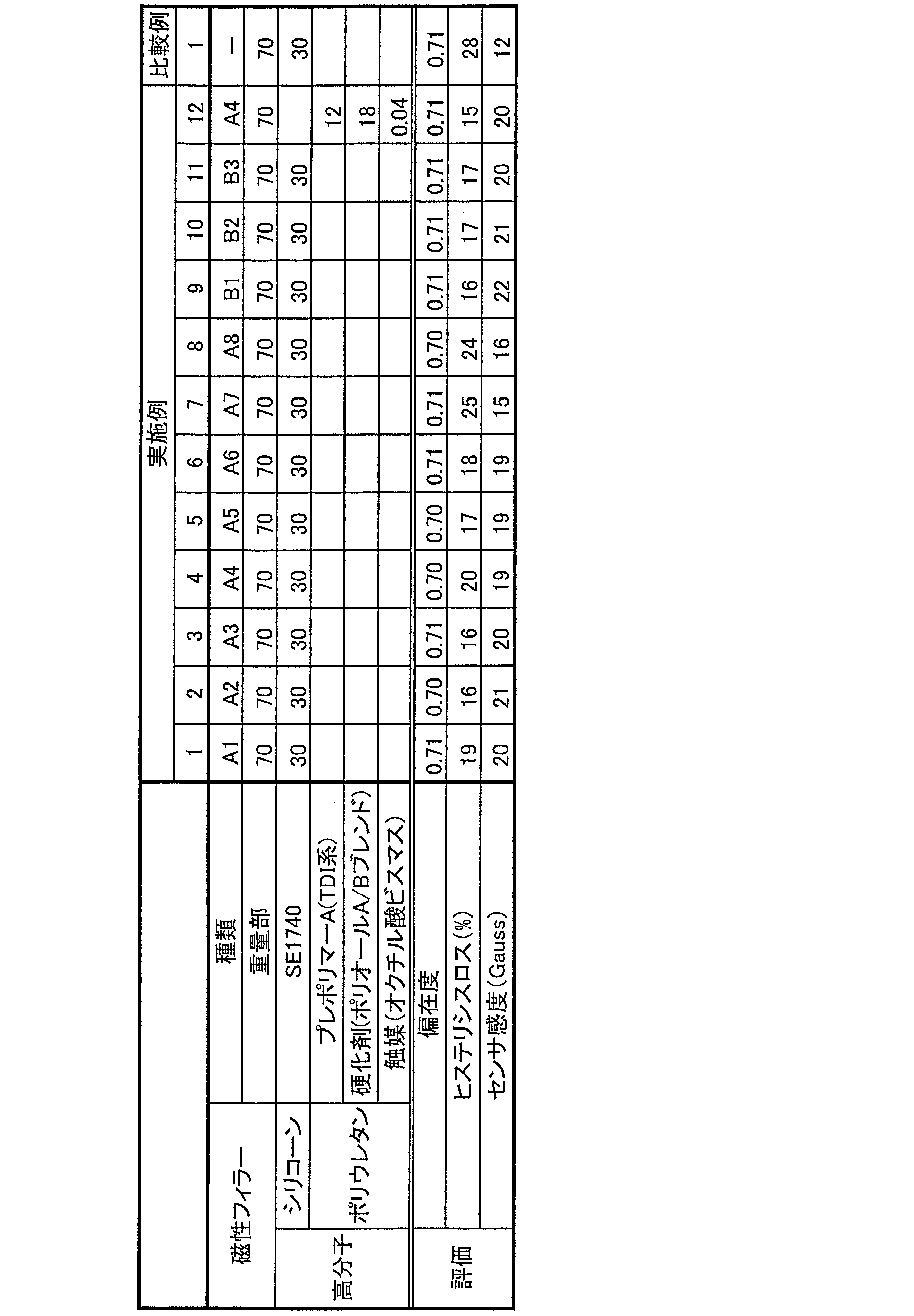
- Examples 2 to 11 A polymer matrix layer was obtained in the same manner as in Example 1 except that the magnetic filler was changed to that shown in Table 2.
- Example 12 In a reaction vessel, EX-3030 (polyoxypropylene glycol added with propylene oxide with glycerin as an initiator, OHV56, functional group number 3, manufactured by Asahi Glass Co., Ltd.) was put in 85.2 parts by weight, and vacuum dehydration was performed for 1 hour with stirring. It was. Thereafter, the inside of the reaction vessel was purged with nitrogen. Next, 14.8 parts by weight of Cosmonate T-100 (toluene diisocyanate, 2,4-form 100%, Mitsui Chemicals) was added to the reaction vessel, and the temperature in the reaction vessel was maintained at 80 ° C.
- Econate T-100 toluene diisocyanate, 2,4-form 100%, Mitsui Chemicals
- EX-3030 8.8 parts by weight of EX-2020 (polyoxypropylene glycol obtained by adding propylene oxide to propylene glycol as an initiator, OHV56, functional group number 2, manufactured by Asahi Glass Co., Ltd.) 25 (Nippon Kagaku Sangyo Co., Ltd. bismuth octylate solution, bismuth content 25%) 0.04 parts by weight of a mixed liquid was added 70 parts by weight of silane-coupled magnetic filler A4 to prepare a magnetic filler dispersion. .
- Example 1 A polymer matrix layer was obtained in the same manner as in Example 1 except that NdFeB magnetic powder (manufactured by Moricope Magnequen Co., Ltd., MQP-14-12, average particle size 45 ⁇ m) that had not been surface-treated was used as the magnetic filler.
- NdFeB magnetic powder manufactured by Moricope Magnequen Co., Ltd., MQP-14-12, average particle size 45 ⁇ m
- the prepared polymer matrix layer was cut into a size of ⁇ 12 and attached to an aluminum plate having a thickness of 1 mm.
- a Hall element (Asahi Kasei Electronics Co., Ltd., EQ-431L) was attached.
- the autopolymer AG-X manufactured by Shimadzu Corporation is used to compress and deform for 5 cycles at a compression rate of 10 to 14% so that the magnetic polymer matrix is entirely compressed. It was.
- the change in magnetic flux density is measured by the difference between the output voltage of the Hall element output at 10% compression deformation and the output voltage of the Hall element output at 12% compression deformation with respect to the thickness of the polymer matrix layer. Sensitivity was used. The measurement was performed 5 times and the average value was obtained. The average values obtained are shown in Table 2. The measurement temperature was 20 ° C. The larger the value, the higher the performance of the sensor.
Landscapes
- Engineering & Computer Science (AREA)
- Manufacturing & Machinery (AREA)
- Chemical & Material Sciences (AREA)
- Chemical Kinetics & Catalysis (AREA)
- Electrochemistry (AREA)
- General Chemical & Material Sciences (AREA)
- Physics & Mathematics (AREA)
- General Physics & Mathematics (AREA)
- Measurement Of Length, Angles, Or The Like Using Electric Or Magnetic Means (AREA)
- Battery Mounting, Suspending (AREA)
- Coating Of Shaped Articles Made Of Macromolecular Substances (AREA)
- Sealing Battery Cases Or Jackets (AREA)
- Secondary Cells (AREA)
Abstract
本発明の密閉型二次電池の変形検出センサは、高分子マトリックス層と、検出部とを備え、前記高分子マトリックス層は、高分子と、磁性フィラーと、カップリング剤とを有し、前記高分子は、前記高分子マトリックス層のマトリックスを形成し、前記磁性フィラーは、前記高分子マトリックス層の変形に応じて磁場に変化を与え、前記検出部は前記磁場の変化を検出する。本発明の密閉型二次電池の変形検出センサによれば、より高感度で安定性に優れた密閉型二次電池の変形検出センサを提供することができる。
Description
本発明は、密閉型二次電池の変形を検出するセンサと、それが取り付けられた密閉型二次電池と、密閉型二次電池の変形を検出する方法とに関する。
近年、リチウムイオン二次電池に代表される密閉型二次電池(以下、単に「二次電池」とも称する)は、携帯電話やノートパソコンなどのモバイル機器だけでなく、電気自動車やハイブリッド車といった電動車両用の電源としても利用されている。二次電池を構成する単電池(セル)は、正極と負極をそれらの間にセパレータを介して捲回または積層してなる電極群と、その電極群を収容する外装体とを備える。一般には、外装体としてラミネートフィルムや金属缶が用いられ、その内部の密閉空間に電極群が電解液とともに収容される。
二次電池は、上述した電動車両用の電源のように高電圧が必要とされる用途において、複数の単電池を含む電池モジュールまたは電池パックの形態で用いられる。電池モジュールでは、直列に接続された複数の単電池が筐体内に収容され、例えば4つの単電池が2並列2直列に、又は4直列に接続される。また、電池パックでは、直列に接続された複数の電池モジュールに加えて、コントローラなどの諸般の機器が筐体内に収容される。電動車両用の電源に用いられる二次電池では、電池パックの筐体が車載に適した形状に形成されている。
かかる二次電池には、過充電などに起因して電解液が分解されると、その分解ガスによる内圧の上昇に伴って単電池が膨らみ、二次電池が変形するという問題がある。その場合、充電電流または放電電流が停止されないと発火を起こし、最悪の結果として二次電池の破裂に至る。したがって、二次電池の破裂を未然に防止するうえでは、充電電流や放電電流を適時に停止できるように、単電池の膨れによる二次電池の変形を高感度に検出することが重要になる。
上述の課題に対し、下記特許文献1には、高分子マトリックス層と、検出部とを備え、前記高分子マトリックス層が、その高分子マトリックス層の変形に応じて外場に変化を与えるフィラーを分散させて含有し、前記検出部が前記外場の変化を検出する密閉型二次電池の変形検出センサが開示されている。前記変形検出センサは、単電池の膨れによって二次電池に変形が生じると、それに応じて磁性フィラーを含有する高分子マトリックス層が変形し、その高分子マトリックス層の変形に伴う磁場の変化を検出部が検出することによって二次電池の変形を検出する。
しかしながら、従来の密閉型二次電池の変形検出センサにはセンサの感度及びセンサの安定性について改良の余地があった。
本発明は、より高感度で安定性に優れた密閉型二次電池の変形検出センサと、それが取り付けられた密閉型二次電池と、密閉型二次電池の変形検出方法とを提供する。
本発明の密閉型二次電池の変形検出センサは、高分子マトリックス層と、検出部とを備え、前記高分子マトリックス層は、高分子と、磁性フィラーと、カップリング剤とを有し、前記高分子は、前記高分子マトリックス層のマトリックスを形成し、前記磁性フィラーは、前記高分子マトリックス層の変形に応じて磁場に変化を与え、前記検出部は前記磁場の変化を検出する。
本発明の密閉型二次電池は、前記変形検出センサが取り付けられていることを特徴とする。
本発明の密閉型二次電池の変形検出方法は、前記変形検出センサを用いることを特徴とする。
本発明によれば、より高感度で安定性に優れた密閉型二次電池の変形検出センサと、密閉型二次電池と、密閉型二次電池の変形検出方法とを提供することができる。本発明の密閉型二次電池の変形検出センサ等がこの様な効果を奏する理由は定かではないが以下のように考えられる。
従来の変形検出センサの感度及び安定性が比較的低いのは、高分子と磁性フィラーの接着性が十分ではなく、高分子マトリックス層が変形した際に高分子と磁性フィラーの界面で摩擦によるエネルギー損失が生じたり、磁性フィラーの追従性が低かったりすることが原因と考えられる。本発明の変形検出センサは、カップリング剤によってマトリックスである高分子と磁性フィラーの接着性を向上させることにより、当該界面での摩擦によるエネルギー損失が減少してセンサの安定性が向上すると考えられる。また、高分子と磁性フィラーの接着性を向上させることにより、磁性フィラーが高分子マトリックス層の変形に追従しやすくなるためセンサ感度が向上すると考えられる。
以下、本発明の一実施形態について図面を参照しつつ説明する。
図1は、密閉型二次電池の変形検出センサ(以下、単に「変形検出センサ」とも称する)を内部に有する電池モジュール1の斜視図であり、図2は図1の電池モジュール1のA-A矢視断面図である。
前記電池モジュール1は、筐体2、単電池3、及び変形検出センサ4を備える。前記単電池3は前記筐体2の内部にあり、当該単電池3には前記変形検出センサ4が取り付けられている。当該変形検出センサ4は、高分子マトリックス層41と、検出部42とを備え、前記高分子マトリックス層41は、高分子と、磁性フィラーと、カップリング剤とを有し、前記高分子は、前記高分子マトリックス層41のマトリックスを形成し、前記磁性フィラーは、前記高分子マトリックス層41の変形に応じて磁場に変化を与え、前記検出部42は前記磁場の変化を検出する。
前記電池モジュール1は、例えば、電動車両用の電源として使用され得るリチウムイオン二次電池であり、車両には電池パックの形態で搭載される。当該電池パックでは、直列に接続された複数の前記電池モジュール1が、コントローラなどの諸般の機器と共に筐体内に収容される。電池パックの筐体2は、車載に適した形状に、例えば車両の床下形状に合わせた形状に形成される。前記密閉型二次電池3は、リチウムイオン電池などの非水系電解液二次電池に限られず、ニッケル水素電池などの水系電解液二次電池であっても構わない。
図2で示される前記電池モジュール1の内部では、4つの単電池3が直列に(例えば2並列2直列に、または4直列に)接続され、二次電池を構成している。前記単電池3は、正極と負極をそれらの間にセパレータを介して捲回または積層してなる電極群と、その電極群を収容する外装体とを備え、外装体の内部の密閉空間には、電極群が電解液とともに収容されている(図示せず)。前記単電池3の外装体には、アルミラミネート箔などのラミネートフィルムが用いられるが、これに代えて円筒型または角型の金属缶を使用してもよい。
前記高分子マトリックス層41は、前記単電池3の表面(外装体の外面)に貼り付けられ、その貼付には必要に応じて接着剤や接着テープが用いられる。前記高分子マトリックス層41はシート状に形成されていて、二次電池における間隙内、例えば互いに隣り合う単電池3の間隙内や、図3で示すように、単電池3とそれを収容する筐体2との間に配置される。前記高分子マトリックス層41を折り曲げるようにして、前記単電池3や前記筐体2の角部に貼り付けることも可能である。
前記高分子マトリックス層41は、当該高分子マトリックス層41の変形に応じて磁場に変化を与える前記磁性フィラーを含有する。前記検出部42は、その磁場の変化を検出する。前記検出部42は、磁場の変化を検出可能な程度で前記高分子マトリックス層41から離して配置され、好ましくは前記単電池3の膨れによる影響を受けにくい比較的堅固な箇所に貼り付けられる。本実施形態では、前記筐体2の外面に前記検出部42を貼り付けているが、これに限られず、前記筐体2の内面や電池パックの筐体に前記検出部42を貼り付けても構わない。これらの筐体は、例えば金属またはプラスチックにより形成され、電池モジュールの筐体にはラミネートフィルムが用いられる場合もある。
図2で示した前記電池モジュール1において、前記高分子マトリックス層41は、前記変形検出センサ4の間隙内に挟まれて圧縮状態で装着されていることが好ましい。前記高分子マトリックス層41の非圧縮状態での厚みは、それが配置される間隙G1よりも大きく、前記高分子マトリックス層41は厚み方向に圧縮されている。図3に示した前記高分子マトリックス層41もまた、間隙内で挟まれて装着されており、この例では前記単電池3と前記筐体2との間隙内で挟まれて装着されている。その高分子マトリックス層41の非圧縮状態での厚みは、それが配置される間隙G2よりも大きく、この高分子マトリックス層41も厚み方向に圧縮されていることが好ましい。
前記高分子マトリックス層41の非圧縮状態での厚みは、好ましくは50~4000μm、より好ましくは100~3000μm、更に好ましくは300~2500μmである。上記の厚みが50μmよりも小さいと、所要量の前記磁性フィラーを添加しようとした際に脆くなってハンドリング性が悪化する傾向にある。一方、上記の厚みが4000μmよりも大きいと、上記の如き間隙内に配置する際に高分子マトリックス層41が過度に圧縮されて変形しにくくなり、センサ感度が低下する場合がある。
前記単電池3が膨れると、それに応じて前記高分子マトリックス層41が変形し、その高分子マトリックス層41の変形に伴う磁場の変化が前記検出部42によって検出される。前記検出部42から出力された検出信号は不図示の制御装置に送られ、設定値以上の磁場の変化が前記検出部42により検出された場合には、その制御装置に接続された不図示のスイッチング回路が通電を遮断し、充電電流または放電電流を停止する。このようにして、前記単電池3の変形が高感度に検出され、破裂が未然に防止される。この変形検出センサ4は、前記単電池3を圧迫せず、位置ずれが抑えられることでセンサ特性が安定する。
図2、3の例では、それぞれ高分子マトリックス層41と検出部42を1つずつ示しているが、単電池3の形状や大きさなどの諸条件に応じて、それらを複数使用してもよい。その際、図2のように装着された高分子マトリックス層41と、図3のように装着された高分子マトリックス層41とが併存しても構わない。更に、複数の高分子マトリックス層41を同じ単電池3に貼り付けたり、複数の検出部42によって同じ高分子マトリックス層41の変形に伴う外場の変化を検出するように構成したりしてもよい。
前記高分子としては、例えばエラストマー成分を使用することができ、エラストマー成分としては、任意に使用可能である。当該エラストマー成分としては、熱可塑性エラストマー、熱硬化性エラストマーまたはそれらの混合物を用いることができる。熱可塑性エラストマーとしては、例えばスチレン系熱可塑性エラストマー、ポリオレフィン系熱可塑性エラストマー、ポリウレタン系熱可塑性エラストマー、ポリエステル系熱可塑性エラストマー、ポリアミド系熱可塑性エラストマー、ポリブタジエン系熱可塑性エラストマー、ポリイソプレン系熱可塑性エラストマー、フッ素ゴム系熱可塑性エラストマー等を挙げることができる。また、熱硬化性エラストマーとしては、例えばポリイソプレンゴム、ポリブタジエンゴム、スチレン-ブタジエンゴム、ポリクロロプレンゴム、ニトリルゴム、エチレン-プロピレンゴム等のジエン系合成ゴム、エチレン-プロピレンゴム、ブチルゴム、アクリルゴム、ポリウレタンゴム、フッ素ゴム、シリコーンゴム、エピクロルヒドリンゴム等の非ジエン系合成ゴム、および天然ゴム等を挙げることができる。このうち好ましいのは熱硬化性エラストマーであり、これは電池の発熱や過負荷に伴う磁性エラストマーのへたりを抑制できるためである。更に好ましくは、ポリウレタンゴム(ポリウレタンエラストマーともいう)またはシリコーンゴム(シリコーンエラストマーともいう)である。
前記ポリウレタンエラストマーは、活性水素含有化合物とイソシアネート成分とを反応させることにより得られる。ポリウレタンエラストマーをエラストマー成分として用いる場合、活性水素含有化合物と磁性フィラーとを混合し、ここにイソシアネート成分を混合させて混合液を得る。また、イソシアネート成分に磁性フィラーを混合し、活性水素含有化合物を混合させることで混合液を得ることも出来る。その混合液を離型処理したモールド内に注型し、その後硬化温度まで加熱して硬化することにより、磁性エラストマーを製造することができる。また、シリコーンエラストマーをエラストマー成分として用いる場合、シリコーンエラストマーの前駆体に磁性フィラーを入れて混合し、型内に入れ、その後加熱して硬化させることにより磁性エラストマーを製造することができる。なお、必要に応じて溶剤を添加してもよい。
前記ポリウレタンエラストマーに使用できるイソシアネート成分としては、ポリウレタンの分野において公知の化合物を使用できる。例えば、2,4-トルエンジイソシアネート、2,6-トルエンジイソシアネート、2,2’-ジフェニルメタンジイソシアネート、2,4’-ジフェニルメタンジイソシアネート、4,4’-ジフェニルメタンジイソシアネート、1,5-ナフタレンジイソシアネート、p-フェニレンジイソシアネート、m-フェニレンジイソシアネート、p-キシリレンジイソシアネート、m-キシリレンジイソシアネート等の芳香族ジイソシアネート、エチレンジイソシアネート、2,2,4-トリメチルヘキサメチレンジイソシアネート、1,6-ヘキサメチレンジイソシアネート等の脂肪族ジイソシアネート、1,4-シクロヘキサンジイソシアネート、4,4’-ジシクロへキシルメタンジイソシアネート、イソホロンジイソシアネート、ノルボルナンジイソシアネート等の脂環式ジイソシアネートを挙げることができる。これらは1種で用いても、2種以上を混合して用いてもよい。また、イソシアネート成分は、ウレタン変性、アロファネート変性、ビウレット変性、及びイソシアヌレート変性等の変性化したものであってもよい。好ましいイソシアネート成分は、2,4-トルエンジイソシアネート、2,6-トルエンジイソシアネート、4,4’-ジフェニルメタンジシソシアネート、より好ましくは2,4-トルエンジイソシアネート、2,6-トルエンジイソシアネートである。
前記活性水素含有化合物としては、ポリウレタンの技術分野において、通常用いられるものを用いることができる。例えば、ポリテトラメチレングリコール、ポリプロピレングリコール、ポリエチレングリコール、プロピレンオキサイドとエチレンオキサイドの共重合体等に代表されるポリエーテルポリオール、ポリブチレンアジペート、ポリエチレンアジペート、3-メチル-1,5-ペンタンアジペートに代表されるポリエステルポリオール、ポリカプロラクトンポリオール、ポリカプロラクトンのようなポリエステルグリコールとアルキレンカーボネートとの反応物などで例示されるポリエステルポリカーボネートポリオール、エチレンカーボネートを多価アルコールと反応させ、次いで得られた反応混合物を有機ジカルボン酸と反応させたポリエステルポリカーボネートポリオール、ポリヒドロキシル化合物とアリールカーボネートとのエステル交換反応により得られるポリカーボネートポリオール等の高分子量ポリオールを挙げることができる。これらは単独で用いてもよく、2種以上を併用してもよい。
前記活性水素含有化合物として上述した高分子量ポリオール成分の他に、エチレングリコール、1,2-プロピレングリコール、1,3-プロピレングリコール、1,4-ブタンジオール、1,6-ヘキサンジオール、ネオペンチルグリコール、1,4-シクロヘキサンジメタノール、3-メチル-1,5-ペンタンジオール、ジエチレングリコール、トリエチレングリコール、1,4-ビス(2-ヒドロキシエトキシ)ベンゼン、トリメチロールプロパン、グリセリン、1,2,6-ヘキサントリオール、ペンタエリスリトール、テトラメチロールシクロヘキサン、メチルグルコシド、ソルビトール、マンニトール、ズルシトール、スクロース、2,2,6,6-テトラキス(ヒドロキシメチル)シクロヘキサノール、及びトリエタノールアミン等の低分子量ポリオール成分、エチレンジアミン、トリレンジアミン、ジフェニルメタンジアミン、ジエチレントリアミン等の低分子量ポリアミン成分を用いてもよい。これらは1種単独で用いてもよく、2種以上を併用してもよい。更に、4,4’-メチレンビス(o-クロロアニリン)(MOCA)、2,6-ジクロロ-p-フェニレンジアミン、4,4’-メチレンビス(2,3-ジクロロアニリン)、3,5-ビス(メチルチオ)-2,4-トルエンジアミン、3,5-ビス(メチルチオ)-2,6-トルエンジアミン、3,5-ジエチルトルエン-2,4-ジアミン、3,5-ジエチルトルエン-2,6-ジアミン、トリメチレングリコール-ジ-p-アミノベンゾエート、ポリテトラメチレンオキシド-ジ-p-アミノベンゾエート、1,2-ビス(2-アミノフェニルチオ)エタン、4,4’-ジアミノ-3,3’-ジエチル-5,5’-ジメチルジフェニルメタン、N,N’-ジ-sec-ブチル-4,4’-ジアミノジフェニルメタン、4,4’-ジアミノ-3,3’-ジエチルジフェニルメタン、4,4’-ジアミノ-3,3’-ジエチル-5,5’-ジメチルジフェニルメタン、4,4’-ジアミノ-3,3’-ジイソプロピル-5,5’-ジメチルジフェニルメタン、4,4’-ジアミノ-3,3’,5,5’-テトラエチルジフェニルメタン、4,4’-ジアミノ-3,3’,5,5’-テトライソプロピルジフェニルメタン、m-キシリレンジアミン、N,N’-ジ-sec-ブチル-p-フェニレンジアミン、m-フェニレンジアミン、及びp-キシリレンジアミン等に例示されるポリアミン類を混合することもできる。好ましい活性水素含有化合物は、ポリテトラメチレングリコール、ポリプロピレングリコール、プロピレンオキサイドとエチレンオキサイドの共重合体、3-メチル-1,5-ペンタンアジペート、より好ましくはポリプロピレングリコール、プロピレンオキサイドとエチレンオキサイドの共重合体である。
また、第3級アミン触媒や、金属触媒等のポリウレタン反応を促進する公知の触媒を使用してもかまわない。前記第3級アミンとしては、トリエチレンジアミン(1,4-ジアザビシクロ[2,2,2]オクタン)、N,N,N’,N’‐テトラメチルヘキサンジアミン、ビス(2-ジメチルアミノエチル)エーテル等が例示できる。前記金属触媒としては、オクチル酸錫、オクチル酸鉛、オクチル酸亜鉛、オクチル酸ビスマス等が例示できる。これらは単独で用いてもよく、2種以上を併用してもよい。
上記触媒の市販品として、東ソー社製の「TEDA-L33」、モメンティブ・パフォーマンス・マテリアルズ社製の「NIAX CATALYST A1」、花王社製の「カオーライザー NO.1」、「カオーライザー NO.30P」、エアプロダクツ社製の「DABCO T-9」、東栄化工社製の「BTT-24」、日本化学産業社製の「プキャット25」などが挙げられる。
前記高分子にポリウレタンエラストマーを用いる場合、そのNCO indexは、好ましくは0.3~1.2、より好ましくは0.5~1.1、更に好ましく0.7~1.05である。NCO indexが0.3より小さいと、ポリウレタンの硬化が不十分になる傾向にあり、NCO indexが1.2より大きいと、弾性率が高くなり、センサ感度が低下する傾向にある。
前記高分子にシリコーンエラストマーを用いる場合、用いられるシリコーンエラストマーは特に限定されないが、前記磁性フィラーを分散させる観点から、2液加熱タイプの付加反応型シリコーンエラストマーが好ましい。この様なシリコーンエラストマーとしては、KE-1204、KE-1031、KE-106、KE-109、KE-1281(以上、信越シリコーン社製)、EE1840、SH850、SE1815CV、SE1816CV、SE9207、SE1740(以上、東レ・ダウコーニング社製)等が挙げられる。
前記高分子マトリックス層41のマトリックスは、気泡を含む発泡体であってもよく、気泡を含まない無発泡体であってもよい。
前記磁性フィラーとしては、希土類系、鉄系、コバルト系、ニッケル系、酸化物系などが挙げられるが、カップリング剤による高分子との接着性の観点から、希土類系磁性フィラーが好ましく、鉄原子を含有する希土類系磁性フィラーがより好ましい。鉄原子を含有する希土類系磁性フィラーとしては、NdFeB磁粉(モリコープ・マグネクエンチ社製、MQP-14-12)、SmFeN磁粉、SmCo磁粉等が例示できる。
前記磁性フィラーの形状は、特に限定されるものではなく、球状、扁平状、針状、柱状および不定形のいずれであってよい。磁性フィラーの平均粒径は、好ましくは0.02~500μm、より好ましくは0.1~400μm、更に好ましくは0.5~300μmである。平均粒径が0.02μmより小さいと、磁性フィラーの磁気特性が低下する傾向にあり、平均粒径が500μmを超えると、磁性エラストマー層の機械的特性が低下して脆くなる傾向にある。
前記高分子マトリックス層41中の前記磁性フィラーの含有量は、前記高分子100重量部に対して、好ましくは1~450重量部、より好ましくは2~400重量部である。これが1重量部より少ないと、磁場の変化を検出することが難しくなる傾向にあり、450重量部を超えると、前記高分子マトリックス層41が脆くなる場合がある。
前記磁性フィラーは、着磁後のものマトリックスに導入してもよく、マトリックスに導入した状態で着磁してもよい。磁性フィラーの取り扱いの観点からは、高分子マトリックス層41に含まれた状態で着磁するのが好ましい。磁性フィラーの着磁方法は特に限定されず、通常用いられる着磁装置、例えば電子磁気工業株式会社製の「ES-10100-15SH」、株式会社玉川製作所製の「TM-YS4E」、東英工業株式会社製の「MPM-08」などを用いて行うことができる。通常、磁束密度1~4Tを有する磁場を印加する。
前記磁性フィラーは、マトリックス中に分散された状態で含まれていてもよく、高分子マトリックス層41の厚み方向に偏在した状態で含まれていてもよい。フィラーを偏在させる方法としては、例えば、硬化前の高分子に磁性フィラーを導入した後、室温あるいは所定の温度で静置し、その磁性フィラーの重さにより自然沈降させる方法を使用でき、静置する温度や時間を変化させることでフィラー偏在率を調整できる。遠心力や磁力のような物理的な力を用いて、磁性フィラーを偏在させてもよい。
前記カップリング剤としては、シランカップリング剤、チタネートカップリング剤、及びアルミニウムカップリング剤等が例示できるが、高分子と磁性フィラーの接着性向上の観点からシランカップリング剤が好ましい。シランカップリング剤としては、3-アミノプロピルトリメトキシシラン 、N-2-(アミノエチル)-3-アミノプロピルメチルジメトキシシラン、3-トリエトキシシリル-N-(1,3-ジメチルブチリデン)プロピルアミン、N-フェニル-γ-アミノプロピルトリメトキシシラン等のアミノシランや、3-グリシドキシプロピルメチルジメトキシシラン、3-グリシドキシプロピルトリメトキシシラン、3-グリシドキシプロピルトリエトキシシラン、3-グリシドキシプロピルメチルジエトキシシラン、3-グリシドキシプロピルトリエトキシシラン等のエポキシシラン、3-メタクリロキシプロピルメチルジメトキシシラン、3-メタクリロキシプロピルトリメトキシシラン、3-メタクリロキシプロピルメチルジエトキシシラン、3-メタクリロキシプロピルトリエトキシシラン等のメタクリロキシシラン、例えば、ビニルメトキシシラン、ビニルトリエトキシシラン等のビニルシラン、ウレイドシラン、メルカプトシラン、スルフィドシラン、アクリロキシシラン等が用いられる。好ましくは、アミノシラン、エポキシシラン、ビニルシラン、メタクリロシランである。
前記高分子マトリックス層41中の前記カップリング剤の含有量は、前記高分子100重量部に対して、好ましくは0.0007~0.245重量部、より好ましくは0.0021~0.224重量部である。これが0.0007重量部より少ないと、前記カップリング剤の効果が得られにくい傾向にあり、0.245重量部を超えると、高分子が硬化阻害を引き起こす傾向にある。
前記カップリング剤は、高分子と磁性フィラーの接着性向上の観点から、マトリックスに分散された状態で前記高分子マトリックス層41に含まれていても良く、前記磁性フィラーを前記カップリング剤で表面処理し、当該表面処理された磁性フィラーを用いることによって前記高分子マトリックス層41に含まれていても良い。高分子と磁性フィラーの接着性向上の観点から、前記カップリング剤で表面処理された前記磁性フィラーを用いるのが好ましい。
前記磁性フィラーを前記カップリング剤で表面処理する方法は特に限定されず、カップリング剤について通常用いられている表面処理方法を適用することができる。一例として、前記カップリング剤がシランカップリング剤である場合に当該シランカップリング剤について通常用いられている表面処理方法としては、シランカップリング剤を前記磁性フィラーにスプレーした後、混合する乾式法や、有機溶媒に前記磁性フィラー、前記シランカップリング剤が分散している有機溶媒に前記磁性フィラーを分散させて撹拌する湿式法が挙げられるが、前記磁性フィラーの表面に前記シランカップリング剤をより効率的に反応させる観点から、湿式法が好ましい。
前記湿式法としては、例えば、前記磁性フィラーが分散された有機溶媒にシランカップリング剤を添加するシランカップリング剤添加工程(a1)、前記シランカップリング剤を加水分解する加水分解工程(a2)、及び加水分解工程後、熱処理を行う熱処理工程(a3)を有する磁性フィラーの表面処理方法が挙げられる。
前記シランカップリング剤添加工程(a1)において、前記磁性フィラーを分散させる有機溶媒は特に限定されないが、例えば、トルエンが挙げられる。
前記加水分解工程(a2)で前記シランカップリング剤を加水分解反応させる。前記シランカップリング剤を加水分解反応させるための水の添加方法は特に限定されないが、例えば、前記シランカップリング剤添加工程(a1)で前記シランカップリング剤を添加する際、水に分散させたシランカップリング剤を添加する方法や、前記シランカップリング剤添加工程(a1)後に、前記磁性フィラーと前記シランカップリング剤が分散された有機溶媒に水を添加する方法が挙げられる。
前記シランカップリング剤添加工程(a1)における前記シランカップリング剤の添加量は、前記磁性フィラー100重量部に対して好ましくは0.001~0.35重量部、より好ましくは0.003~0.32重量部である。これが0.001重量部より少ないと、前記カップリング剤の効果が得られにくい傾向にあり、0.35重量部を超えると硬化阻害を引き起こす傾向にある。
前記熱処理工程(a3)では、電気炉などのヒーターで加熱・乾燥させる。熱処理条件は、特に限定されず、例えば、100℃以上で、30分間~3時間程度である。
前記シランカップリング剤で表面処理された磁性フィラーを用いる場合、当該磁性フィラーのX線光電子分光法(XPS)から算出されるケイ素の原子数と鉄の原子数の比(ケイ素原子数/鉄原子数)は、高分子と磁性フィラーの接着性向上の観点から、0.05~1.00が好ましく、0.01~0.80がより好ましい。ケイ素の原子数と鉄の原子数の比は、より具体的には実施例に記載の方法により測定する。
前記磁性フィラーを前記シランカップリング剤で表面処理する場合、高分子と磁性フィラーの接着性向上の観点から、前記シランカップリング剤による表面処理の前処理として、金属アルコキシドで前記磁性フィラーの表面を処理するのが好ましい。当該金属アルコキシドとしては、高分子と磁性フィラーの接着性向上の観点から、チタンアルコキシド及びアルミニウムアルコキシドからなる群より選ばれる1種以上が好ましく、チタンアルコキシドがより好ましい。
前記チタンアルコキシドとしては、チタンテトラメトキシド、チタンテトラエトキシド、チタンテトラプロポキシド、チタンテトライソプロポキシド、チタンテトラブトキシド、チタンテトラsec-ブトキシド、チタンテトラtert-ブトキシド等が例示できる。
前記アルミニウムアルコキシドとしては、アルミニウムメトキシド、アルミニウムエトキシド、アルミニウムプロポキシド、アルミニウムイソプロポキシド、アルミニウムブトキシド、アルミニウムイソブトキシド等が例示できる。
前記磁性フィラーを前記金属アルコキシドで表面処理する方法は特に限定されず、金属アルコキシドについて通常用いられている表面処理方法を適用することができる。金属アルコキシドについて通常用いられている表面処理方法としては、金属アルコキシドを前記磁性フィラーにスプレーした後、混合する乾式法や、有機溶媒に前記磁性フィラー、前記金属アルコキシドが分散している有機溶媒に前記磁性フィラーを分散させて撹拌する湿式法が挙げられるが、前記磁性フィラーの表面に前記金属アルコキシドをより効率的に反応させる観点から、湿式法が好ましい。
前記湿式法としては、例えば、前記磁性フィラーが分散された有機溶媒に金属アルコキシドを添加する金属アルコキシド添加工程(b1)、前記金属アルコキシドを加水分解する加水分解工程(b2)、及び加水分解工程後、熱処理を行う熱処理工程(b3)を有する磁性フィラーの表面処理方法が挙げられる。
前記金属アルコキシド添加工程(b1)において、前記磁性フィラーを分散させる有機溶媒は特に限定されないが、例えば、トルエンが挙げられる。
前記加水分解工程(b2)で前記金属アルコキシドを加水分解反応させる。前記金属アルコキシドを加水分解反応させるための水の添加方法は特に限定されないが、例えば、前記金属アルコキシド添加工程(b1)で前記金属アルコキシドを添加する際、水に分散させた金属アルコキシドを添加する方法や、前記金属アルコキシド添加工程(b1)後に、前記磁性フィラーと前記金属アルコキシドが分散された有機溶媒に水を添加する方法が挙げられる。
前記金属アルコキシド添加工程(b1)における前記金属アルコキシドの添加量は、前記磁性フィラー100重量部に対して好ましくは0.005~0.50重量部である。これが0.005重量部より少ないと、前記金属アルコキシドの効果が得られにくい傾向にあり、0.50重量部を超えると硬化阻害を引き起こす傾向にある。
前記熱処理工程(b3)では、電気炉などのヒーターで加熱・乾燥させる。熱処理条件は、特に限定されず、例えば、100℃以上で、30分間~3時間程度である。
前記金属アルコキシドで表面処理された磁性フィラーを用いる場合、当該磁性フィラーのX線光電子分光法(XPS)から算出されるチタンの原子数及びアルミニウムの原子数の合計と鉄の原子数の比(チタンの原子数及びアルミニウムの原子数の合計/鉄の原子数)は、高分子と磁性フィラーの接着性向上の観点から、0.05~1.00が好ましく、0.10~0.80がより好ましい。チタンの原子数及びアルミニウムの原子数の合計と鉄の原子数の比は、より具体的には実施例に記載の方法により測定する。
磁場の変化を検出する前記検出部42は、例えば、磁気抵抗素子、ホール素子、インダクタ、MI素子、フラックスゲートセンサなどを用いることができる。磁気抵抗素子としては、半導体化合物磁気抵抗素子、異方性磁気抵抗素子(AMR)、巨大磁気抵抗素子(GMR)、トンネル磁気抵抗素子(TMR)が挙げられる。このうち好ましいのはホール素子であり、これは広範囲にわたって高い感度を有する前記検出部42として有用なためである。
本発明は上述した実施形態に何ら限定されるものではなく、本発明の趣旨を逸脱しない範囲内で種々の改良変更が可能である。
前述の実施形態では、高分子マトリックス層41が、互いに隣り合う単電池3の間隙内で挟まれる例(図2参照)と、単電池3と筐体2との間隙内で挟まれる例(図3参照)を示したが、これに限定されない。例えば、電池パックに含まれる電池モジュールの筐体とその隣の電池モジュールの筐体との間で、即ち互いに隣り合う電池モジュールの筐体の間隙内で、高分子マトリックス層が挟まれてもよく、特にラミネートフィルム型の電池モジュールにおいて有用である。電池モジュールの筐体と電池パックの筐体との間隙内で、高分子マトリックス層が挟まれるものでもよい。さらに高分子マトリックス層は、単電池内に配設されても良く、例えば正極とセパレータとの間、負極とセパレータとの間、或いは正極と外装体との間、負極と外装体との間、さらにはセパレータと外装体との間に挟まれるように配設されても良く、特に正極/セパレータ/負極を巻回して構成する円筒型または角型の単電池用の変形検出センサとして使用する場合において有用である。
<磁性フィラーの調製>
〔磁性フィラーA1〕
反応容器にトルエン130重量部、NdFeB磁粉(モリコープ・マグネクエンチ社製、MQP-14-12、平均粒径45μm)100重量部を入れ、磁性フィラー分散液Aを調製した。次に、ビニルメトキシシラン(信越化学工業株式会社製、シランカップリング剤、KBM-1003)0.00354重量部、テトラヒドロフラン1重量部を混合した後、蒸留水0.00043重量部を加え、十分に撹拌し、混合液Aを得た。この混合液Aを磁性フィラー分散液Aに添加し、室温で16時間加水分解反応させた。続いて、この分散液Aをデカンテーションにより反応溶液と磁性フィラーに分離した後、反応溶液を除去した。残った磁性フィラーを、トルエンを用いて3回洗浄し、100℃で3時間熱処理を行ってシランカップリング剤処理済みの磁性フィラーA1を得た。
〔磁性フィラーA1〕
反応容器にトルエン130重量部、NdFeB磁粉(モリコープ・マグネクエンチ社製、MQP-14-12、平均粒径45μm)100重量部を入れ、磁性フィラー分散液Aを調製した。次に、ビニルメトキシシラン(信越化学工業株式会社製、シランカップリング剤、KBM-1003)0.00354重量部、テトラヒドロフラン1重量部を混合した後、蒸留水0.00043重量部を加え、十分に撹拌し、混合液Aを得た。この混合液Aを磁性フィラー分散液Aに添加し、室温で16時間加水分解反応させた。続いて、この分散液Aをデカンテーションにより反応溶液と磁性フィラーに分離した後、反応溶液を除去した。残った磁性フィラーを、トルエンを用いて3回洗浄し、100℃で3時間熱処理を行ってシランカップリング剤処理済みの磁性フィラーA1を得た。
〔磁性フィラーA2~A8〕
シランカップリング剤の種類、及び量等を表1に記載の内容に変更した以外は前記磁性フィラーA1と同様にして磁性フィラーA2~A8を得た。
シランカップリング剤の種類、及び量等を表1に記載の内容に変更した以外は前記磁性フィラーA1と同様にして磁性フィラーA2~A8を得た。
〔磁性フィラーB1〕
[金属アルコキシド処理]
反応容器にトルエン130重量部、NdFeB磁粉(モリコープ・マグネクエンチ社製、MQP-14-12、平均粒径45μm)100重量部を入れ、磁性フィラー分散液Bを調製した。次に、チタンテトラブトキシド(ナカライテスク株式会社製)0.00813重量部、テトラヒドロフラン1重量部を混合した後、蒸留水0.00043重量部を加え、十分に撹拌し、混合液Bを得た。この混合液Bを磁性フィラー分散液Bに添加し、室温で16時間加水分解反応させた。続いて、分散液Bをデカンテーションにより反応溶液と磁性フィラーに分離した後、反応溶液を除去した。残った磁性フィラーを、トルエンを用いて3回洗浄し、100℃で3時間熱処理を行って金属アルコキシド処理済みの磁性フィラーb1を得た。
[金属アルコキシド処理]
反応容器にトルエン130重量部、NdFeB磁粉(モリコープ・マグネクエンチ社製、MQP-14-12、平均粒径45μm)100重量部を入れ、磁性フィラー分散液Bを調製した。次に、チタンテトラブトキシド(ナカライテスク株式会社製)0.00813重量部、テトラヒドロフラン1重量部を混合した後、蒸留水0.00043重量部を加え、十分に撹拌し、混合液Bを得た。この混合液Bを磁性フィラー分散液Bに添加し、室温で16時間加水分解反応させた。続いて、分散液Bをデカンテーションにより反応溶液と磁性フィラーに分離した後、反応溶液を除去した。残った磁性フィラーを、トルエンを用いて3回洗浄し、100℃で3時間熱処理を行って金属アルコキシド処理済みの磁性フィラーb1を得た。
[シランカップリング剤処理]
反応容器にトルエン130重量部、金属アルコキシド処理済み磁性フィラーb1 100重量部を入れ、磁性フィラー分散液Cを調製した。次に、ビニルメトキシシラン(信越化学工業株式会社製、シランカップリング剤、KBM-1003)0.00354重量部、テトラヒドロフラン1重量部を混合した後、蒸留水0.00043重量部を加え、十分に撹拌し、混合液Cを得た。この混合液Cを磁性フィラー分散液Cに添加し、室温で16時間加水分解反応させた。続いて、この分散液Cをデカンテーションにより反応溶液と磁性フィラーに分離した後、反応溶液を除去した。残った磁性フィラーを、トルエンを用いて3回洗浄し、100℃で3時間熱処理を行ってシランカップリング剤処理済みの磁性フィラーB1を得た。
反応容器にトルエン130重量部、金属アルコキシド処理済み磁性フィラーb1 100重量部を入れ、磁性フィラー分散液Cを調製した。次に、ビニルメトキシシラン(信越化学工業株式会社製、シランカップリング剤、KBM-1003)0.00354重量部、テトラヒドロフラン1重量部を混合した後、蒸留水0.00043重量部を加え、十分に撹拌し、混合液Cを得た。この混合液Cを磁性フィラー分散液Cに添加し、室温で16時間加水分解反応させた。続いて、この分散液Cをデカンテーションにより反応溶液と磁性フィラーに分離した後、反応溶液を除去した。残った磁性フィラーを、トルエンを用いて3回洗浄し、100℃で3時間熱処理を行ってシランカップリング剤処理済みの磁性フィラーB1を得た。
〔磁性フィラーB2、B3〕
シランカップリング剤の種類、及び量等を表1に記載の内容に変更した以外は前記磁性フィラーB1と同様にして磁性フィラーB2、B3を得た。
シランカップリング剤の種類、及び量等を表1に記載の内容に変更した以外は前記磁性フィラーB1と同様にして磁性フィラーB2、B3を得た。
<評価方法>
〔Si原子数/Fe原子数比〕
X線光電子分光分析装置(ESCA-5700CI:アルバック・ファイ社製)を用いて、X線源:AlKα、出力:150W、光電子脱出角度:45°の条件で前記磁性フィラーA1~A8、及びB1~3のそれぞれについてSi2s及びFe2pの結合エネルギーのピークを測定した。Si2sとFe2pの検出ピークの各ピーク強度から相対感度係数法を用いて比率を算出し、これをケイ素の原子数と鉄の原子数の比(Si原子数/Fe原子数)とした。
〔Si原子数/Fe原子数比〕
X線光電子分光分析装置(ESCA-5700CI:アルバック・ファイ社製)を用いて、X線源:AlKα、出力:150W、光電子脱出角度:45°の条件で前記磁性フィラーA1~A8、及びB1~3のそれぞれについてSi2s及びFe2pの結合エネルギーのピークを測定した。Si2sとFe2pの検出ピークの各ピーク強度から相対感度係数法を用いて比率を算出し、これをケイ素の原子数と鉄の原子数の比(Si原子数/Fe原子数)とした。
〔Ti原子数/Fe原子数比〕
X線光電子分光分析装置(ESCA-5700CI:アルバック・ファイ社製)を用いて、X線源:AlKα、出力:150W、光電子脱出角度:45°の条件で前記磁性フィラーB1~3のそれぞれについてTi2p及びFe2pの結合エネルギーのピークを測定した。Ti2pとFe2pの検出ピークの各ピーク強度から相対感度係数法を用いて比率を算出し、これをチタンの原子数と鉄の原子数の比(Ti原子数/Fe原子数)とした。
X線光電子分光分析装置(ESCA-5700CI:アルバック・ファイ社製)を用いて、X線源:AlKα、出力:150W、光電子脱出角度:45°の条件で前記磁性フィラーB1~3のそれぞれについてTi2p及びFe2pの結合エネルギーのピークを測定した。Ti2pとFe2pの検出ピークの各ピーク強度から相対感度係数法を用いて比率を算出し、これをチタンの原子数と鉄の原子数の比(Ti原子数/Fe原子数)とした。
〔Al原子数/Fe原子数比〕
前記Ti原子数/Fe原子数比の算出と同様の方法でAl2p及びFe2pの結合エネルギーのピークを測定し、Al2pとFe2pの検出ピークの各ピーク強度から相対感度係数法を用いて比率を算出することによって、アルミニウムの原子数と鉄の原子数の比(Al原子数/Fe原子数)を求めることができる。
前記Ti原子数/Fe原子数比の算出と同様の方法でAl2p及びFe2pの結合エネルギーのピークを測定し、Al2pとFe2pの検出ピークの各ピーク強度から相対感度係数法を用いて比率を算出することによって、アルミニウムの原子数と鉄の原子数の比(Al原子数/Fe原子数)を求めることができる。

<実施例1>
反応容器にSE1740A(東レ・ダウコーニング社製シリコーンエラストマー)15.0重量部、シランカップリング剤処理済み磁性フィラーA1 70.0重量部を添加した後、SE1740B(東レ・ダウコーニング社製シリコーンエラストマー)15.0重量部を添加し、自転・公転ミキサー(シンキー社製)にて混合、および脱泡を行った。この反応液を2.5mmのスペーサーを有する離型処理したPETフィルム上に滴下し、ニップロールにて厚み2.5mmに調整した。その後、90℃で18時間硬化を行って、磁性フィラー含有高分子マトリックスを得た。これを着磁装置(東英工業社製、MPM-08型)にて、4.0Tで着磁することにより、高分子マトリックス層を得た。
反応容器にSE1740A(東レ・ダウコーニング社製シリコーンエラストマー)15.0重量部、シランカップリング剤処理済み磁性フィラーA1 70.0重量部を添加した後、SE1740B(東レ・ダウコーニング社製シリコーンエラストマー)15.0重量部を添加し、自転・公転ミキサー(シンキー社製)にて混合、および脱泡を行った。この反応液を2.5mmのスペーサーを有する離型処理したPETフィルム上に滴下し、ニップロールにて厚み2.5mmに調整した。その後、90℃で18時間硬化を行って、磁性フィラー含有高分子マトリックスを得た。これを着磁装置(東英工業社製、MPM-08型)にて、4.0Tで着磁することにより、高分子マトリックス層を得た。
<実施例2~11>
磁性フィラーを表2に記載のものに変更した以外は実施例1と同様にして高分子マトリックス層を得た。
磁性フィラーを表2に記載のものに変更した以外は実施例1と同様にして高分子マトリックス層を得た。
<実施例12>
反応容器に、EX-3030(グリセリンを開始剤にプロピレンオキサイドを付加したポリオキシプロピレングリコール、OHV56、官能基数3、旭硝子社製)を85.2重量部入れ、撹拌しながら減圧脱水を1時間行った。その後、反応容器内を窒素置換した。次いで、反応容器にコスモネートT-100(トルエンジイソシアネート、2,4-体100%、三井化学社製)を14.8重量部添加して、反応容器内の温度を80℃に保持しながら5時間反応させて、イソシアネート末端プレポリマーA(NCO%=3.58%)を合成した。次に、EX-3030 8.8重量部、EX-2020(プロピレングリコールを開始剤にプロピレンオキサイドを付加したポリオキシプロピレングリコール、OHV56、官能基数2、旭硝子社製)8.8重量部、及びプキャット25(日本化学産業社製オクチル酸ビスマス溶液、ビスマス含有量25%)0.04重量部の混合液に、シランカップリング処理済み磁性フィラーA4 70重量部を添加し、磁性フィラー分散液を調製した。これにプレポリマーA12重量部を添加し、自転・公転ミキサー(シンキー社製)にて混合、および脱泡を行った。この反応液を2.5mmのスペーサーを有する離型処理したPETフィルム上に滴下し、ニップロールにて厚み2.5mmに調整した。その後、90℃で18時間硬化を行って、磁性フィラー含有高分子マトリックスを得た。これを着磁装置(東英工業社製、MPM-08型)にて、4.0Tで着磁することにより、高分子マトリックス層を得た。
反応容器に、EX-3030(グリセリンを開始剤にプロピレンオキサイドを付加したポリオキシプロピレングリコール、OHV56、官能基数3、旭硝子社製)を85.2重量部入れ、撹拌しながら減圧脱水を1時間行った。その後、反応容器内を窒素置換した。次いで、反応容器にコスモネートT-100(トルエンジイソシアネート、2,4-体100%、三井化学社製)を14.8重量部添加して、反応容器内の温度を80℃に保持しながら5時間反応させて、イソシアネート末端プレポリマーA(NCO%=3.58%)を合成した。次に、EX-3030 8.8重量部、EX-2020(プロピレングリコールを開始剤にプロピレンオキサイドを付加したポリオキシプロピレングリコール、OHV56、官能基数2、旭硝子社製)8.8重量部、及びプキャット25(日本化学産業社製オクチル酸ビスマス溶液、ビスマス含有量25%)0.04重量部の混合液に、シランカップリング処理済み磁性フィラーA4 70重量部を添加し、磁性フィラー分散液を調製した。これにプレポリマーA12重量部を添加し、自転・公転ミキサー(シンキー社製)にて混合、および脱泡を行った。この反応液を2.5mmのスペーサーを有する離型処理したPETフィルム上に滴下し、ニップロールにて厚み2.5mmに調整した。その後、90℃で18時間硬化を行って、磁性フィラー含有高分子マトリックスを得た。これを着磁装置(東英工業社製、MPM-08型)にて、4.0Tで着磁することにより、高分子マトリックス層を得た。
<比較例1>
磁性フィラーに表面処理をしていないNdFeB磁粉(モリコープ・マグネクエンチ社製、MQP-14-12、平均粒径45μm)を用いた以外は実施例1と同様にして高分子マトリックス層を得た。
磁性フィラーに表面処理をしていないNdFeB磁粉(モリコープ・マグネクエンチ社製、MQP-14-12、平均粒径45μm)を用いた以外は実施例1と同様にして高分子マトリックス層を得た。
<評価方法>
〔偏在度〕
走査型電子顕微鏡-エネルギー分散型X線分析装置(SEM-EDS)(SEM:日立ハイテクノロジーズ社製S-3500N、EDS:堀場製作所製EMAXモデル7021-H)を用いて、加速電圧25kV、真空度50Pa、WD15mmの条件にて各高分子マトリックス層の断面を60倍で観察した。その断面の厚み方向全体の領域と、その断面を厚み方向に二等分した2つの領域に対し、それぞれ元素分析によりフィラー固有の金属元素(本願ではFe元素)の存在量を求めた。この存在量について、厚み方向全体の領域に対してフィラー量が多い側での比率を算出し、これを偏在度とした。
〔偏在度〕
走査型電子顕微鏡-エネルギー分散型X線分析装置(SEM-EDS)(SEM:日立ハイテクノロジーズ社製S-3500N、EDS:堀場製作所製EMAXモデル7021-H)を用いて、加速電圧25kV、真空度50Pa、WD15mmの条件にて各高分子マトリックス層の断面を60倍で観察した。その断面の厚み方向全体の領域と、その断面を厚み方向に二等分した2つの領域に対し、それぞれ元素分析によりフィラー固有の金属元素(本願ではFe元素)の存在量を求めた。この存在量について、厚み方向全体の領域に対してフィラー量が多い側での比率を算出し、これを偏在度とした。
〔センサ感度〕
作製した高分子マトリックス層をφ12の大きさに切り出し、厚み1mmのアルミ板に貼り付けた。その反対面にホール素子(旭化成エレクトロニクス株式会社製、EQ-431L)を取り付けた。次に、φ30mmの面圧子を用いて、磁性高分子マトリックスが全面圧縮されるようにオートグラフAG-X(島津製作所社製)を用いて、10~14%の圧縮率で5サイクル圧縮変形させた。高分子マトリックス層の厚みに対して10%圧縮変形時に出力されるホール素子の出力電圧と、12%圧縮変形時に出力されるホール素子の出力電圧との差により磁束密度の変化を計測し、センサ感度とした。測定は、5回実施し、その平均値を求めた。求めた平均値を表2に記す。なお、測定温度は20℃とした。値が大きいほど、センサとして高性能である。
作製した高分子マトリックス層をφ12の大きさに切り出し、厚み1mmのアルミ板に貼り付けた。その反対面にホール素子(旭化成エレクトロニクス株式会社製、EQ-431L)を取り付けた。次に、φ30mmの面圧子を用いて、磁性高分子マトリックスが全面圧縮されるようにオートグラフAG-X(島津製作所社製)を用いて、10~14%の圧縮率で5サイクル圧縮変形させた。高分子マトリックス層の厚みに対して10%圧縮変形時に出力されるホール素子の出力電圧と、12%圧縮変形時に出力されるホール素子の出力電圧との差により磁束密度の変化を計測し、センサ感度とした。測定は、5回実施し、その平均値を求めた。求めた平均値を表2に記す。なお、測定温度は20℃とした。値が大きいほど、センサとして高性能である。
〔ヒステリシスロス〕
上記センサ感度の測定の際の5サイクル目におけるヒステリシスロス(%)を表に記す。値が小さいほど、センサとしての安定性(再現性)に優れている。
上記センサ感度の測定の際の5サイクル目におけるヒステリシスロス(%)を表に記す。値が小さいほど、センサとしての安定性(再現性)に優れている。
1 電池モジュール
2 筐体
3 単電池3
4 変形検出センサ
41 高分子マトリックス層
42 検出部
2 筐体
3 単電池3
4 変形検出センサ
41 高分子マトリックス層
42 検出部
Claims (14)
- 密閉型二次電池の変形検出センサにおいて、
高分子マトリックス層と、検出部とを備え、
前記高分子マトリックス層は、高分子と、磁性フィラーと、カップリング剤とを有し、
前記高分子は、前記高分子マトリックス層のマトリックスを形成し、
前記磁性フィラーは、前記高分子マトリックス層の変形に応じて磁場に変化を与え、
前記検出部は前記磁場の変化を検出する、密閉型二次電池の変形検出センサ。 - 前記カップリング剤が、シランカップリング剤である、請求項1に記載の密閉型二次電池の変形検出センサ。
- 前記磁性フィラーが、鉄原子を含有する希土類系磁性フィラーである、請求項1又は2に記載の密閉型二次電池の変形検出センサ。
- 前記磁性フィラーが、前記シランカップリング剤で表面処理されている、請求項3に記載の密閉型二次電池の変形検出センサ。
- 前記シランカップリング剤で表面処理された前記磁性フィラーの、X線光電子分光法から算出されるケイ素の原子数と鉄の原子数の比(ケイ素の原子数/鉄の原子数)が、0.05~1.00である、請求項4に記載の密閉型二次電池の変形検出センサ。
- 前記磁性フィラーが、金属アルコキシドで表面処理されている、請求項1~5いずれか1項に記載の密閉型二次電池の変形検出センサ。
- 前記金属アルコキシドがチタンアルコキシド及びアルミニウムアルコキシドからなる群より選ばれる1種以上であり、
前記金属アルコキシドで表面処理された前記磁性フィラーの、X線光電子分光法から算出されるチタンの原子数及びアルミニウムの原子数の合計と鉄の原子数の比(チタンの原子数及びアルミニウムの原子数の合計/鉄の原子数)が、0.05~1.00である、請求項6に記載の密閉型二次電池の変形検出センサ。 - 前記高分子が、ポリウレタンエラストマー又はシリコーンエラストマーである、請求項1~7いずれか1項に記載の密閉型二次電池の変形検出センサ。
- 請求項1~8いずれか1項に記載の変形検出センサが取り付けられた密閉型二次電池。
- 請求項1~8いずれか1項に記載の変形検出センサを用いて密閉型二次電池の変形を検出する、密閉型二次電池の変形検出方法。
- 請求項4又は5に記載の密閉型二次電池の変形検出センサの製造方法であって、
シランカップリング剤処理工程を含み、
当該シランカップリング剤処理工程が、前記磁性フィラーが分散された有機溶媒にシランカップリング剤を添加するシランカップリング剤添加工程、前記シランカップリング剤を加水分解する加水分解工程、及び加水分解工程後、熱処理を行う熱処理工程を有する、密閉型二次電池の変形検出センサの製造方法。 - 前記シランカップリング剤添加工程における前記シランカップリング剤の添加量が、前記磁性フィラー100重量部に対して0.001~0.35重量部である請求項11に記載の密閉型二次電池の変形検出センサの製造方法。
- 前記シランカップリング剤処理工程の前に、更に、金属アルコキシド処理工程を有し、
当該金属アルコキシド処理工程が、前記磁性フィラーが分散された有機溶媒に金属アルコキシドを添加する金属アルコキシド添加工程、前記金属アルコキシドを加水分解する加水分解工程、及び加水分解工程後、熱処理を行う熱処理工程を有する、請求項11又は12に記載の密閉型二次電池の変形検出センサの製造方法。 - 前記金属アルコキシドの添加量が磁性フィラー100重量部に対して0.005~0.50重量部であることを特徴とする請求項11~13いずれか1項に記載の密閉型二次電池の変形検出センサの製造方法。
Applications Claiming Priority (2)
| Application Number | Priority Date | Filing Date | Title |
|---|---|---|---|
| JP2016-232208 | 2016-11-30 | ||
| JP2016232208A JP2018087797A (ja) | 2016-11-30 | 2016-11-30 | 密閉型二次電池の変形検出センサ、密閉型二次電池、及び密閉型二次電池の変形検出方法 |
Publications (1)
| Publication Number | Publication Date |
|---|---|
| WO2018100798A1 true WO2018100798A1 (ja) | 2018-06-07 |
Family
ID=62241412
Family Applications (1)
| Application Number | Title | Priority Date | Filing Date |
|---|---|---|---|
| PCT/JP2017/027240 Ceased WO2018100798A1 (ja) | 2016-11-30 | 2017-07-27 | 密閉型二次電池の変形検出センサ、密閉型二次電池、及び密閉型二次電池の変形検出方法 |
Country Status (2)
| Country | Link |
|---|---|
| JP (1) | JP2018087797A (ja) |
| WO (1) | WO2018100798A1 (ja) |
Cited By (2)
| Publication number | Priority date | Publication date | Assignee | Title |
|---|---|---|---|---|
| CN109082253A (zh) * | 2018-06-25 | 2018-12-25 | 南亚新材料科技股份有限公司 | 一种高分散性的无卤素粘合剂及其制备方法 |
| WO2021131430A1 (ja) * | 2019-12-24 | 2021-07-01 | 富士フイルム株式会社 | 音響レンズ用組成物、音響レンズ、音響波プローブ、超音波プローブ、音響波測定装置、超音波診断装置、光音響波測定装置及び超音波内視鏡並びに音響波プローブの製造方法 |
Families Citing this family (1)
| Publication number | Priority date | Publication date | Assignee | Title |
|---|---|---|---|---|
| CN115863730B (zh) * | 2021-09-27 | 2023-12-15 | 宁德时代新能源科技股份有限公司 | 夹具、夹持电池的方法、加热系统、电池加热及冷压方法 |
Citations (4)
| Publication number | Priority date | Publication date | Assignee | Title |
|---|---|---|---|---|
| JP2006156423A (ja) * | 2003-07-09 | 2006-06-15 | Bridgestone Corp | ゴム磁石シートおよびゴム磁石シートの製造方法 |
| WO2011029575A1 (de) * | 2009-09-08 | 2011-03-17 | Carl Freudenberg Kg | Magnetschaumsensor |
| WO2015151331A1 (ja) * | 2014-03-31 | 2015-10-08 | 東洋ゴム工業株式会社 | 密閉型二次電池用変形検知センサ |
| JP2016099193A (ja) * | 2014-11-20 | 2016-05-30 | 東洋ゴム工業株式会社 | 密閉型二次電池の変形検出センサの製造方法 |
-
2016
- 2016-11-30 JP JP2016232208A patent/JP2018087797A/ja active Pending
-
2017
- 2017-07-27 WO PCT/JP2017/027240 patent/WO2018100798A1/ja not_active Ceased
Patent Citations (4)
| Publication number | Priority date | Publication date | Assignee | Title |
|---|---|---|---|---|
| JP2006156423A (ja) * | 2003-07-09 | 2006-06-15 | Bridgestone Corp | ゴム磁石シートおよびゴム磁石シートの製造方法 |
| WO2011029575A1 (de) * | 2009-09-08 | 2011-03-17 | Carl Freudenberg Kg | Magnetschaumsensor |
| WO2015151331A1 (ja) * | 2014-03-31 | 2015-10-08 | 東洋ゴム工業株式会社 | 密閉型二次電池用変形検知センサ |
| JP2016099193A (ja) * | 2014-11-20 | 2016-05-30 | 東洋ゴム工業株式会社 | 密閉型二次電池の変形検出センサの製造方法 |
Cited By (6)
| Publication number | Priority date | Publication date | Assignee | Title |
|---|---|---|---|---|
| CN109082253A (zh) * | 2018-06-25 | 2018-12-25 | 南亚新材料科技股份有限公司 | 一种高分散性的无卤素粘合剂及其制备方法 |
| WO2021131430A1 (ja) * | 2019-12-24 | 2021-07-01 | 富士フイルム株式会社 | 音響レンズ用組成物、音響レンズ、音響波プローブ、超音波プローブ、音響波測定装置、超音波診断装置、光音響波測定装置及び超音波内視鏡並びに音響波プローブの製造方法 |
| JPWO2021131430A1 (ja) * | 2019-12-24 | 2021-07-01 | ||
| CN114930875A (zh) * | 2019-12-24 | 2022-08-19 | 富士胶片株式会社 | 声透镜用组合物、声透镜、声波探头、超声波探头、声波测定装置、超声波诊断装置、光声波测定装置及超声波内窥镜以及声波探头的制造方法 |
| JP7351929B2 (ja) | 2019-12-24 | 2023-09-27 | 富士フイルム株式会社 | 音響レンズ用組成物、音響レンズ、音響波プローブ、超音波プローブ、音響波測定装置、超音波診断装置、光音響波測定装置及び超音波内視鏡並びに音響波プローブの製造方法 |
| CN114930875B (zh) * | 2019-12-24 | 2025-04-29 | 富士胶片株式会社 | 声透镜用组合物、声透镜、声波探头、超声波探头、声波测定装置、超声波诊断装置、光声波测定装置及超声波内窥镜以及声波探头的制造方法 |
Also Published As
| Publication number | Publication date |
|---|---|
| JP2018087797A (ja) | 2018-06-07 |
Similar Documents
| Publication | Publication Date | Title |
|---|---|---|
| JP6265847B2 (ja) | 密閉型二次電池の変形検出センサ、密閉型二次電池、及び、密閉型二次電池の変形検出方法 | |
| JP6306155B2 (ja) | 密閉型二次電池用変形検知センサ | |
| JP6186339B2 (ja) | 密閉型二次電池の監視センサ、密閉型二次電池、及び、密閉型二次電池の監視方法 | |
| JP6296670B2 (ja) | 密閉型二次電池の変形検出センサ、密閉型二次電池、及び、密閉型二次電池の変形検出方法 | |
| JP6200880B2 (ja) | 密閉型二次電池の変形検出方法、及び、密閉型二次電池 | |
| JP6339439B2 (ja) | 密閉型二次電池の変形検出センサ、密閉型二次電池、及び、密閉型二次電池の変形検出方法 | |
| WO2016084620A1 (ja) | 密閉型二次電池の監視センサ、密閉型二次電池、及び、密閉型二次電池の監視方法 | |
| WO2018078912A1 (ja) | 密閉型二次電池の変形検出センサ、及び密閉型二次電池 | |
| WO2016084427A1 (ja) | 密閉型二次電池の変形検出センサ | |
| WO2016080027A1 (ja) | 密閉型二次電池の変形検出センサの製造方法 | |
| WO2018100798A1 (ja) | 密閉型二次電池の変形検出センサ、密閉型二次電池、及び密閉型二次電池の変形検出方法 | |
| JP6290727B2 (ja) | 密閉型二次電池の変形検出センサ、密閉型二次電池、及び、密閉型二次電池の変形検出方法 | |
| JP6310806B2 (ja) | 密閉型二次電池の変形検出センサおよびその製造方法、密閉型二次電池、ならびに密閉型二次電池の変形検出方法 | |
| JP2018137161A (ja) | 密閉型二次電池の監視センサ、監視センサの製造方法、密閉型二次電池 | |
| JP2018044909A (ja) | 密閉型二次電池の変形検出センサ | |
| WO2018066163A1 (ja) | 可撓性永久磁石の製造方法、可撓性永久磁石、変形検出センサ及び変形検出方法 | |
| JP2018137162A (ja) | 密閉型二次電池の監視センサ、監視センサの製造方法、密閉型二次電池 | |
| JP6310805B2 (ja) | 密閉型二次電池の変形検出センサおよびその製造方法、密閉型二次電池、ならびに密閉型二次電池の変形検出方法 | |
| WO2018163832A1 (ja) | 可撓性永久磁石の製造方法、可撓性永久磁石、変形検出センサ及び変形検出方法 | |
| WO2018163833A1 (ja) | 可撓性永久磁石の製造方法、可撓性永久磁石、変形検出センサ及び変形検出方法 | |
| WO2018066162A1 (ja) | 可撓性永久磁石の製造方法、可撓性永久磁石、変形検出センサ及び変形検出方法 | |
| JP2018044907A (ja) | 密閉型二次電池の変形検出センサ | |
| WO2018230268A1 (ja) | 監視センサ、及び密閉型二次電池 | |
| JP2019220348A (ja) | 二次電池の変形検出システム、方法及びプログラム |
Legal Events
| Date | Code | Title | Description |
|---|---|---|---|
| 121 | Ep: the epo has been informed by wipo that ep was designated in this application |
Ref document number: 17875428 Country of ref document: EP Kind code of ref document: A1 |
|
| NENP | Non-entry into the national phase |
Ref country code: DE |
|
| 122 | Ep: pct application non-entry in european phase |
Ref document number: 17875428 Country of ref document: EP Kind code of ref document: A1 |