WO2018097099A1 - 基材評価方法および屈曲ガラス評価装置 - Google Patents
基材評価方法および屈曲ガラス評価装置 Download PDFInfo
- Publication number
- WO2018097099A1 WO2018097099A1 PCT/JP2017/041666 JP2017041666W WO2018097099A1 WO 2018097099 A1 WO2018097099 A1 WO 2018097099A1 JP 2017041666 W JP2017041666 W JP 2017041666W WO 2018097099 A1 WO2018097099 A1 WO 2018097099A1
- Authority
- WO
- WIPO (PCT)
- Prior art keywords
- base material
- evaluation
- main surface
- curvature
- jig
- Prior art date
- Legal status (The legal status is an assumption and is not a legal conclusion. Google has not performed a legal analysis and makes no representation as to the accuracy of the status listed.)
- Ceased
Links
Images



Classifications
-
- G—PHYSICS
- G01—MEASURING; TESTING
- G01N—INVESTIGATING OR ANALYSING MATERIALS BY DETERMINING THEIR CHEMICAL OR PHYSICAL PROPERTIES
- G01N3/00—Investigating strength properties of solid materials by application of mechanical stress
- G01N3/56—Investigating resistance to wear or abrasion
-
- G—PHYSICS
- G01—MEASURING; TESTING
- G01N—INVESTIGATING OR ANALYSING MATERIALS BY DETERMINING THEIR CHEMICAL OR PHYSICAL PROPERTIES
- G01N13/00—Investigating surface or boundary effects, e.g. wetting power; Investigating diffusion effects; Analysing materials by determining surface, boundary, or diffusion effects
-
- G—PHYSICS
- G01—MEASURING; TESTING
- G01N—INVESTIGATING OR ANALYSING MATERIALS BY DETERMINING THEIR CHEMICAL OR PHYSICAL PROPERTIES
- G01N21/00—Investigating or analysing materials by the use of optical means, i.e. using sub-millimetre waves, infrared, visible or ultraviolet light
- G01N21/17—Systems in which incident light is modified in accordance with the properties of the material investigated
- G01N21/59—Transmissivity
Definitions
- the present invention relates to a substrate evaluation method and a bent glass evaluation apparatus.
- Patent Document 1 durability tests such as abrasion resistance and scratch resistance of the surface of objects such as fibers, leather, and lenses have been performed.
- an object such as a lens is brought into contact with a friction element such as cloth or steel wool, and the object and the friction element are moved relative to each other to evaluate the wear resistance of the object.
- a flat base material, a convex base material having a substantially constant curvature like the lens shown in Patent Document 1, and a highly flexible base material such as fiber and leather as in Patent Document 2 and Patent Document 3. use.
- a low-flexible base material provided with a bent portion having a large curvature has been widely used.
- glass having a bent portion is used as a cover glass for a touch panel display. Since the user touches the cover glass, the surface of the cover glass is required to have wear resistance and the like, and it is necessary to perform wear resistance evaluation and the like.
- An object of the present invention is to provide a substrate evaluation method and a bent glass evaluation apparatus capable of performing evaluation and tests such as homogeneous wear resistance evaluation even on a low flexibility substrate having a bent portion with a large curvature. It is to be.
- a substrate evaluation method characterized by evaluating the surface state of one main surface. According to the present invention, when evaluating a base material having a bent portion with an initial shape, the bent portion is deformed into an evaluation shape, so that the surface state of the first main surface of the base material is homogeneous and accurate. And can be measured.
- a base material having a bent portion with an initial shape and a curvature of R1 can be transformed into an evaluation shape so as to have a curvature R2 smaller than R1, and a test method for evaluating a flat base material or It becomes easier to use the measurement method, and homogeneous and accurate evaluation can be performed.
- the base material can be easily transformed into the evaluation shape by the pressure difference.
- the base material can be deformed and fixed from the initial shape to an evaluation shape with a small curvature along the shape of the mounting surface, and a stable base material can be evaluated.
- the base material is sandwiched between a first jig disposed on the first main surface side and a second jig disposed on the second main surface side.
- substrate evaluation method since the base material is sandwiched between the first jig and the second jig, the base material can be stably deformed and fixed.
- the substrate is sandwiched between the surfaces of the first jig and the second jig, and the first jig has an opening that exposes the first main surface.
- Material evaluation method since the first jig includes an opening that exposes the first main surface of the base material, the first main surface is deformed while the base material is deformed into an evaluation shape. Evaluation can be performed.
- the base material is deformed from the initial shape to a desired evaluation shape by coupling the first jig and the second jig with the connection jig and adjusting the tightening degree of the connection member. Can be held stably.
- the curvature radius of the bent portion of the mounting surface in the second jig is r3
- the curvature radius of the bent portion of the curvature R2 after the base material deformation is r2
- the thickness of the base material is t.
- t, the substrate evaluation method according to (8).
- the base material can be deformed and fixed from the initial shape to an evaluation shape with a small curvature along the shape of the mounting surface, and a stable base material can be evaluated.
- the wear resistance evaluation can be easily performed, and accurate evaluation can be performed.
- the base material can be deformed and fixed from the initial shape to the evaluation shape, an accurate evaluation with a small error can be performed in the liquid interface evaluation.
- the base material can be deformed and fixed from the initial shape to the evaluation shape, the optical influence due to the bending of the base material can be minimized, and accurate evaluation can be performed.
- a bent glass evaluation apparatus comprising a fixing mechanism for deforming the curvature of the bent portion with respect to the glass having the first main surface, the second main surface, and the end surface having the bent portion.
- transform a bending part and can be made into an evaluation shape can be provided, and a homogeneous and accurate test and measurement can be implemented.
- the fixing mechanism includes a first jig disposed on the first main surface side and a second jig disposed on the second main surface side.
- the present invention it is possible to provide a substrate evaluation method and a bent glass evaluation apparatus capable of performing a test such as a homogeneous durability test even on a substrate having a low curvature with a bent portion having a large curvature.
- FIG. 1 It is a side view regarding an example of a base-material evaluation apparatus. It is a cross-sectional schematic diagram of a bending board (glass base material which has a bending part), (a) is a shape provided with a bending part and a flat part, (b) is a shape by which the whole becomes a bending part.
- A) is a schematic cross-sectional view of a mounting table as an example of the present embodiment
- (b) is a schematic cross-sectional view of the mounting table when the base material is fixed
- (c) is a mounting table with the base material fixed.
- FIG. (A) And (b) is a cross-sectional schematic diagram of the mounting base as other this embodiment. It is a figure for demonstrating liquid-liquid interface evaluation.
- FIG. 1 the side view at the time of using the abrasion-resistant evaluation apparatus 2 for a base-material evaluation apparatus is shown.
- the wear resistance evaluation apparatus 2 includes a main body frame 21, a horizontal reciprocating device 22, a mounting table 23, a friction jig 24, and a support member 25.
- the main frame 21 includes a horizontal reciprocating device 22, a mounting table 23, a support member 25, a speed adjustment switch 26, a power switch 27, a counter 28, a control device (not shown), a motor, and the like.
- the horizontal reciprocating device 22 has one end connected to the mounting table 23 and the other end connected to a motor or the like, and reciprocates the mounting table 23 horizontally in accordance with the movement of the motor.
- the control device sends a control signal to the motor and controls the number of reciprocating motions of the mounting table 23.
- the number of reciprocations is displayed on the counter 28, and the reciprocating motion is stopped at the set number of times.
- the speed of the reciprocating motion can be arbitrarily adjusted by the speed adjustment switch 26.
- the stroke of the reciprocating motion can be arbitrarily set by changing the cam or the like that operates the horizontal reciprocating motion device 22.
- the horizontal reciprocating device 22 is described as a mechanism for moving the mounting table 23 on which the base material 1 is mounted with respect to the friction jig 24 in the horizontal direction. There is no particular limitation as long as it is relatively reciprocating with respect to 23.
- the friction jig 24 is attached to the other end of the arm 252 having one end connected to the shaft 251 so as to be rotatable with respect to the column 253.
- the friction jig 24 includes a friction element 241, a fixing tool 242, and an adjusting rod 243, and the friction element 241 is fixed by the fixing tool 242.
- the friction element 241 is not particularly limited as long as it is a scratch for use in the wear resistance test.
- a gauze, a cloth such as a gold cloth or cloth for clothing, a metal such as steel wool, or a resin such as an eraser can be used.
- the mounting table 23 includes a mounting surface 231 on which the base material 1 to be evaluated can be mounted, a pedestal 232, and a fixing mechanism 233 (see FIG. 3).
- the mounting surface 231 has a surface shape that can give the base material 1 to be evaluated to a desired evaluation shape, and fixes the base material 1 to which the desired evaluation shape is given by the fixing mechanism 233.
- the substrate 1 has a first main surface 1a, a second main surface 1b, and an end surface 1c as shown in FIG. 2, and has a shape including at least one bent portion 12.
- the bent portion 12 is illustrated as having a radius of curvature r1, the bent portion 12 may further include a bent portion 12 having a different radius of curvature r′1, and the radius of curvature continuously changes from r1 to r′1.
- the portion 12 may be included.
- the curvature radius of the bent portion 12 is the curvature radius with respect to the first main surface 1a.
- the “flat portion” means a portion having an average radius of curvature of more than 5000 mm
- the “bent portion” means a portion having an average radius of curvature of 5000 mm or less.
- the fixing mechanism 233 may sandwich the base material 1 or supply negative pressure, and is not particularly limited as long as it has a mechanism capable of fixing the base material 1.
- FIG. 3A shows a schematic sectional view of a mounting table 23 as an example of the present embodiment.
- the fixing mechanism 233 in the present embodiment includes a first jig 2331 arranged on the first main surface side of the base material 1 and a second jig arranged on the second main surface side of the base material 1.
- a pedestal 232 and a connecting member (screw 2332 and nut 2333) are provided.
- the first jig 2331 has a through hole through which the screw 2332 can penetrate the first jig 2331.
- the base material 1 is placed on the base 232 as the second jig, and the first jig 2331 is placed on the base material 1 so that the screw 2332 passes through the through hole. Then, the nut 2333 is screwed from the other end side of the screw 2332 whose one end is fixed to the base 232. Accordingly, the base material 1 is sandwiched and fixed by the first jig 2331 and the base 232 as the second jig. At this time, the base material 1 is fixed while being deformed from the initial shape to the evaluation shape by tightening the nut 2333.
- the curvature R1 is larger than the curvature R2 when the curvature of the curvature radius r1 in the initial shape of the substrate 1 is R1 and the curvature when the bent portion 12 of the substrate 1 is deformed into the evaluation shape is R2.
- the base material 1 having the bent portion 12 having the curvature R1 in the initial shape is brought into contact with the mounting surface 231 and the fixing mechanism 233 is used to make the evaluation shape in which the bent portion 12 has the curvature R2. preferable.
- Curvature R1 of the bent portion in the initial shape of the substrate 1 is not particularly limited, (100 mm or more 5000mm or less with a radius of curvature r1) 0.2 m -1 or 100 m -1 or less. This is because high designability can be obtained as a bent plate. 0.5 m -1 or 80 m -1 and more preferably less, 0.8 m -1 or 50 m -1 or less is more preferable.
- the curvature R2 of the bent portion in the evaluation shape of the substrate 1 is preferably 0 m ⁇ 1 or more and 2 m ⁇ 1 or less. This is because the uniformity of testing and evaluation can be improved. 0 m -1 or 1 m -1, more preferably less, 0 m -1 or 0.3 m -1 or less is more preferable.
- the tightening pressure may be managed by a torque wrench or the like.
- bent glass glass having a bent portion
- the rigidity of the glass itself is high and the flexibility is low.
- the rigidity of the glass itself is high and the flexibility is low.
- the evaluation result has a large variation.
- the bent glass evaluation apparatus of the present invention the curvature of the bent portion of the bent glass can be deformed, and evaluation is performed under substantially the same evaluation conditions even within the evaluation portion, and an evaluation result with little variation is obtained.
- FIG. 3 (b) shows a schematic cross-sectional view when the substrate 1 is fixed using the mounting table of FIG. 3 (a).
- the second main surface 1 b of the substrate 1 coincides with the placement surface 231 of the pedestal 232.
- the 2nd main surface 1b of the base material 1 is firmly fixed, and it becomes easy to implement accurate evaluation.
- the first main surface 1 a of the base material 1 matches the shape of the contact surface of the first jig 2331. Thereby, the 1st main surface 1a of the base material 1 is also fixed, and more accurate evaluation can be implemented.
- FIG. 3 (c) shows a top view of the mounting table in FIG. 3 (b).
- the first jig 2331 includes a main body 2331a and an opening 2331b. Thereby, since the 1st main surface 1a of the base material 1 is exposed, evaluation of a 1st main surface can be implemented, deform
- the materials of the first jig 2331, the second jig, and the base 232 are not particularly limited. Metal, resin, ceramic, etc. can be used. A resin such as rubber or urethane may be disposed only at a portion in contact with the substrate 1. Thereby, it can fix firmly, suppressing generation
- FIG. 1 A resin such as rubber or urethane may be disposed only at a portion in contact with the substrate 1. Thereby, it can fix firmly, suppressing generation
- the mounting table 23 may be configured such that only the shape of either the first jig 2331 or the base 232 as the second jig is in contact with the base material 1. Further, as shown in FIG. 4B, the mounting table 23 may be provided with a vacuum hole 2334 in the base 232 as the fixing mechanism 233 so that it can be fixed by suction. At this time, the first jig 2331 may be omitted.
- the curvature radius of the bent portion of the mounting surface 231 with the curvature R3 is r3
- the curvature radius of the corresponding bent portion with the curvature R2 of the base material in the evaluation shape after the deformation is r2
- t.
- the substrate evaluation method using the above-described wear resistance evaluation apparatus is as follows.
- the base material evaluation method of the present invention is based on the base material 1 having the first main surface 1a, the second main surface 1b and the end surface having the bent portion 12 so that the curvature of the bent portion 12 is changed.
- the material 1 is deformed and the first main surface 1a of the substrate 1 is evaluated.
- the curvature R1 of the bent portion of the base material 1 in the initial shape is R1
- the curvature when the bent portion 12 of the base material 1 is deformed to the evaluation shape is R2.
- the curvature R1 is larger than the curvature R2. It is preferable to become.
- the deformation of the base material may be performed by sandwiching the first main surface 1a and the second main surface 1b of the base material 1, or a negative pressure may be supplied to the second main surface 1b.
- a mechanism capable of deforming the substrate 1 is provided.
- a mechanism that can deform and fix the substrate 1 as it is is preferable.
- the base material 1 When deforming the base material, it is preferable to provide a difference between the pressure P1 (Pa) of the first main surface 1a of the base material 1 and the pressure P2 (Pa) of the second main surface 2b, and the pressure P1 is a pressure. More preferably, it becomes larger than P2. According to this embodiment, the base material 1 can be easily transformed into an evaluation shape by a pressure difference.
- the second main surface 1b is placed on the pedestal 232 and is negatively placed on the second main surface 1b side. It is preferable to supply pressure. According to this embodiment, it is only necessary to provide equipment capable of supplying negative pressure only on the second main surface 1b side of the base material 1, and the base material can be easily transformed into an evaluation shape.
- an abrasion resistance evaluation apparatus as shown in FIG. 1 is used to evaluate the abrasion resistance of the substrate 1 having an evaluation shape. At this time, it is preferable to evaluate the first main surface 1a of the substrate 1. Moreover, you may mark on the 1st main surface 1a of the base material 1 so that the place and range which want to evaluate may become clear. Thereby, even if it removes the base material 1 from the base 232 for a measurement etc. in the middle of evaluation, the base material 1 can be fixed in the original position again and evaluation can be restarted.
- the method for evaluating the wear resistance using the wear resistance evaluation apparatus 2 is as follows. First, the base material 1 to be evaluated is prepared, the base 232 is deformed from the initial shape to the evaluation shape, and the base material 1 is fixed to the base 232. The base 232 to which the substrate 1 is fixed is connected to the horizontal reciprocating motion device 22 of the wear resistance evaluation device 2.
- the friction jig 24 is attached to the wear resistance evaluation apparatus 2.
- a material such as an eraser or a gold band is processed into a desired shape to form a friction element 241, which is attached to a fixture 242, and this is attached to one end of an adjustment rod 243.
- the adjusting rod 243 is adjusted so that the distance between the first main surface 1a of the substrate 1 and the friction element 241 becomes a desired distance.
- the size of the friction element 241 is not particularly limited as long as it is adjusted according to the evaluation area and the like, but can be appropriately selected from a circular shape having a diameter of 10 mm and a rectangular shape having a length of 20 mm and a width of 10 mm. Further, the friction element 241 may be replaced during the wear resistance evaluation. This is because the friction element 241 may be deteriorated by contact with the base material 1 and needs to be replaced for accurate evaluation.
- An evaluation weight 244 may be placed on the wear resistance evaluation apparatus 2 from the other end side of the adjusting rod 243 according to the wear resistance evaluation condition.
- a plurality of evaluation weights can be used, and the evaluation conditions may be satisfied.
- the evaluation conditions are not particularly limited, but the mass of the evaluation weight is preferably 0.5 kg to 5 kg. Further, the evaluation weight 244 may be placed after adjusting the inclination of the arm 252 with the horizontal adjustment weight 245 of the horizontal adjustment rod 246 in advance.
- the friction element 241 is brought into contact with the first main surface 1a of the base 1 fixed to the base 232 so that a desired load is applied, so that the evaluation can be started.
- adjustment is made with a speed adjustment switch so that the friction element 241 and the substrate 1 can be evaluated at a desired speed. Further, the counter 28 is set so that the friction element 241 and the substrate 1 can be stopped at a desired number of sliding times. In this state, the power switch 27 is turned on to start the evaluation.
- the method for evaluating the wear resistance of the substrate 1 is not particularly limited such as visual observation, microscopic observation, and tactile sensation, but from the viewpoint of facilitating quantitative evaluation, so-called liquid interface evaluation capable of evaluating wettability is preferable.
- liquid interface evaluation capable of evaluating wettability is preferable.
- FIG. 5 shows a side view at the time of evaluating the liquid interface.
- a liquid interface evaluation apparatus is prepared in a state in which the base material 1 after the wear resistance evaluation is fixed to the pedestal 232.
- the liquid interface evaluation apparatus 3 includes a syringe 31 storing a test liquid and a camera 33, and drops the test liquid from the syringe 31 onto the first main surface 1 a of the substrate 1 to form a droplet 32.
- the droplet 32 is observed by the camera 33, and the angle ⁇ formed between the droplet 32 and the first main surface 1a is calculated. This angle can be compared before and after the wear resistance evaluation to indirectly evaluate the wear resistance of the substrate 1. Since the angle ⁇ greatly affects the shape of the base material 1, the influence on the angle ⁇ can be minimized by flattening the first main surface 1 a of the base material 1 by the wear resistance evaluation method described above, Variations can be reduced.
- Test liquid can be used according to the purpose such as pure water, organic liquid such as glycerin.
- organic liquid such as glycerin.
- the evaluation is not limited to the above-described wear resistance evaluation and liquid interface evaluation.
- the chemical resistance evaluation when the chemical resistance evaluation is performed, the test chemical solution can be stably held on the substrate, and an accurate evaluation can be performed.
- the optical property evaluation when the optical property evaluation is performed, the optical influence due to the bending of the base material can be minimized, and the accurate evaluation can be performed.
- the surface shape evaluation is performed, the shape distortion due to the bending of the substrate can be reduced, and the surface shape can be accurately measured and evaluated.
- a measuring apparatus capable of performing these optical characteristic evaluations includes, for example, a light generating unit that generates measurement light, and a light receiving unit that receives information light to which information obtained after the measurement light contacts the evaluation target is added. Prepare. In optical property evaluation, the quantity and quality of information light with added information is important.
- the distance between the light generating portion and the base material is not constant, and the light from the bent portion of the base material or the gap between the light receiving portion and the base material As a result, there is a possibility that the information light is unbalanced or accurate.
- the distance between the light generating portion and the base material can be kept within a certain range, and there is no gap between the light generating portion and the light receiving portion. As a result, mixing of external light can be suppressed, so that optical characteristic evaluation can be performed accurately.
- the present invention is not limited to the above embodiment, and various improvements and design changes can be made without departing from the gist of the present invention.
- the general procedure, structure, and the like may be other structures as long as the object of the present invention can be achieved.
- Examples of the substrate include glass and silicon.
- Examples of the glass include inorganic glass and organic glass.
- Examples of the organic glass include polycarbonate and polymethyl methacrylate.
- the member of the cover member is inorganic glass
- the tempering treatment both physical tempering treatment and chemical tempering treatment can be used, but the chemical tempering treatment is preferable from the viewpoint that a relatively thin glass can be tempered.
- the Young's modulus of the substrate is preferably 50 GPa or more, more preferably 60 GPa or more, and further preferably 70 GPa or more. This deforms the base material provided with the bent portion, and when performing the non-destructive evaluation of the first main surface 1a, it can be deformed to the evaluation shape without damaging the base material. Return to shape.
- limiting in particular in the upper limit of the Young's modulus of a base material From a viewpoint of evaluation, 200 GPa or less is preferable, for example, and 150 GPa or less is more preferable.
- the Young's modulus of the base material can be measured and calculated for a test piece having a length of 20 mm ⁇ width of 20 mm ⁇ thickness of 10 mm using an ultrasonic method based on Japanese Industrial Standard JIS R 1602 (1995).
- the Vickers hardness Hv of the substrate is preferably 400 or more, more preferably 500 or more.
- the base material can be prevented from being scratched or damaged due to contact with the first jig. Thereby, scratches other than the evaluation of the substrate can be suppressed, and the accuracy of the substrate evaluation can be improved.
- the Vickers hardness of the base material of the present embodiment can be measured by a Vickers hardness test described in, for example, Japanese Industrial Standard JIS Z 2244 (2009).
- Processing You may grind and polish at least one main surface of a base material. You may form a hole in at least one part of a base material. The hole may or may not penetrate through the substrate. The end surface of the base material may be subjected to processing such as chamfering. When the substrate is glass, it is preferable to perform processing generally called R chamfering or C chamfering by mechanical grinding, but the processing may be performed by etching or the like, and is not particularly limited. You may implement the process of forming various surface treatment layers and a printing layer in a required place about a base material. Examples of the surface treatment layer include an antireflection treatment layer and an antifouling treatment layer, and these may be used in combination.
Landscapes
- Physics & Mathematics (AREA)
- Health & Medical Sciences (AREA)
- Life Sciences & Earth Sciences (AREA)
- Chemical & Material Sciences (AREA)
- Analytical Chemistry (AREA)
- Biochemistry (AREA)
- General Health & Medical Sciences (AREA)
- General Physics & Mathematics (AREA)
- Immunology (AREA)
- Pathology (AREA)
- Investigating Strength Of Materials By Application Of Mechanical Stress (AREA)
Abstract
基材評価方法は、屈曲部を有する第1の主面と第2の主面と端面とを備えた基材について、前記屈曲部の曲率を変化させるように前記基材を変形し、前記基材の第1の主面の表面状態を評価する。これにより、曲率が大きな屈曲部を備えた柔軟性が低い基材に対しても、均質な耐摩耗性評価等の評価や試験を実施できる。
Description
本発明は、基材評価方法および屈曲ガラス評価装置に関する。
従来から、繊維、皮革、レンズなどの対象物に対し、その表面の耐摩耗性、耐擦傷性といった耐久性試験(例えば、特許文献1)等が実施されている。例えば、レンズなどの対象物に、布やスチールウールといった摩擦子を接触し、対象物と摩擦子を相対運動させて対象物の耐摩耗性評価を実施する。
対象物として、平板状基材、特許文献1に示すレンズのように曲率が小さくほぼ一定の凸面基材、特許文献2や特許文献3のような繊維や皮革といった高い柔軟性をもつ基材を使用する。
ところで、近年、曲率が大きな屈曲部を備えた柔軟性の低い基材が広く用いられつつある。例えば、屈曲部を有するガラスがタッチパネルディスプレイのカバーガラスに用いられる。カバーガラスは使用者が接触するため、カバーガラスの表面には耐摩耗性等が求められ、耐摩耗性評価等を実施する必要がある。
柔軟性の低い屈曲部を備えたガラスについて、従来のような耐摩耗性評価を実施すると、曲率が大きな屈曲部を有するガラスでは、柔軟性が低いため摩擦子が均質に接触できなかった。このため、一定の試験条件または一定の試験条件の範囲で均質な耐摩耗性評価を実施できなかった。
本発明の目的は、曲率が大きな屈曲部を備えた柔軟性が低い基材に対しても、均質な耐摩耗性評価等の評価や試験を実施できる基材評価方法および屈曲ガラス評価装置を提供することである。
(1) 屈曲部を有する第1の主面と第2の主面と端面とを備えた基材について、前記屈曲部の曲率を変化させるように前記基材を変形し、前記基材の第1の主面の表面状態を評価する、ことを特徴とする基材評価方法。
本発明によれば、初期形状で屈曲部を有する基材を評価する際に、屈曲部を変形して評価形状とするため、基材の第1の主面の表面状態に均質かつ正確な試験や計測を実施できるようになる。
(2) 前記基材の屈曲部における曲率R1が、前記基材変形後の屈曲部における曲率R2より大きい、(1)の基材評価方法。
本発明の態様によれば、初期形状で曲率がR1の屈曲部を有する基材を、R1より小さい曲率R2となるように評価形状に変形でき、平板状基材を評価する際の試験方法や計測方法を利用しやすくなり、均質かつ正確な評価を実施できる。
(3) 前記基材を変形する際に、第1の主面側の圧力P1と、第2の主面側の圧力P2とに差を設ける、(1)または(2)の基材評価方法。
本発明の態様によれば、圧力差により簡単に基材を評価形状に変形できる。
(4) 前記基材を変形する際に、前記基材の第2の主面を台座に接触させて載置し、第2の主面側に負圧を供給する、(1)~(3)のいずれかに記載の基材評価方法。
本発明の態様によれば、基材の第2の主面側に負圧を供給できる設備を設ければよく、簡易に基材を評価形状に変形できる。
(5) 前記台座における載置面の屈曲部の曲率半径をr3とし、前記基材変形後の曲率R2の屈曲部における曲率半径をr2とし、前記基材の厚さをtとすると、|r3-r2|=tとなる、(4)の基材評価方法。
本発明の態様によれば、載置面の形状に沿わせて基材を初期形状から曲率の小さい評価形状に変形させ固定でき、安定した基材の評価を実施できる。
(6) 前記基材を変形する際に、第1の主面側に配置する第1治具と第2の主面側に配置する第2治具とで前記基材を挟持する、(1)または(2)の基材評価方法。
本発明の態様によれば、第1治具と第2治具とで基材を挟持させるため、基材を安定的に変形させて固定できる。
(7) 第1治具と第2治具との面で前記基材を挟持し、第1治具には、第1の主面が露出するような開口部がある、(6)の基材評価方法。
本発明の態様によれば、基材の第1の主面が露出するような開口部を第1治具が備えているため、基材を評価形状に変形させつつ、第1の主面の評価を実施できる。
(8) 第1治具と第2治具とが接続部材により結合され、前記基材を変形する、(6)または(7)の基材評価方法。
本発明の態様によれば、第1治具と第2治具とを接続治具で結合し、接続部材の締め込み具合を調整することで、基材を初期形状から所望の評価形状に変形でき、安定に保持できる。
(9) 前記第2治具における載置面の屈曲部の曲率半径をr3とし、前記基材変形後の曲率R2の屈曲部における曲率半径をr2とし、前記基材の厚さをtとすると、|r3-r2|=tとなる、(8)に記載の基材評価方法。
本発明の態様によれば、載置面の形状に沿わせて基材を初期形状から曲率の小さい評価形状に変形させ固定でき、安定した基材の評価を実施できる。
(10) 前記表面状態の評価が耐摩耗性評価である、(1)~(9)のいずれかの基材評価方法。
本発明の態様によれば、基材を初期形状から評価形状に変形し固定できるため、耐摩耗性評価を実施しやすくなり、正確な評価を実施できる。
(11) 前記表面状態の評価が対液体界面評価である、(1)~(9)のいずれかの基材評価方法。
本発明の態様によれば、基材を初期形状から評価形状に変形し固定できるため、対液体界面評価において誤差が小さく正確な評価を実施できる。
(12) 前記表面状態の評価が光学特性評価である、(1)~(9)のいずれかの基材評価方法。
本発明の態様によれば、基材を初期形状から評価形状に変形し固定できるため、基材の屈曲による光学的影響を最小限にでき、正確な評価を実施できる。
(13) 屈曲部を有する第1の主面と第2の主面と端面とを備えたガラスについて、前記屈曲部の曲率を変形する固定機構を備えることを特徴とする屈曲ガラス評価装置。
本発明によれば、初期形状で屈曲部を有する基材を評価する際に、屈曲部を変形して評価形状とできる装置を提供でき、均質かつ正確な試験や計測を実施できる。
(14) 前記固定機構が、第1の主面側に配置する第1治具と、第2の主面側に配置する第2治具とを有する、(13)の屈曲ガラス評価装置。
本発明の態様によれば、第1治具と第2治具とで基材を挟持させるため、基材を安定的に変形させて固定できる。
(15) 第1治具は、第1の主面が露出する開口部を有する、(14)の屈曲ガラス評価装置。
本発明の態様によれば、基材の第1の主面が露出するような開口部を第1治具が備えているため、基材を評価形状に変形させつつ、第1の主面の評価を実施できる。
本発明によれば、初期形状で屈曲部を有する基材を評価する際に、屈曲部を変形して評価形状とするため、基材の第1の主面の表面状態に均質かつ正確な試験や計測を実施できるようになる。
(2) 前記基材の屈曲部における曲率R1が、前記基材変形後の屈曲部における曲率R2より大きい、(1)の基材評価方法。
本発明の態様によれば、初期形状で曲率がR1の屈曲部を有する基材を、R1より小さい曲率R2となるように評価形状に変形でき、平板状基材を評価する際の試験方法や計測方法を利用しやすくなり、均質かつ正確な評価を実施できる。
(3) 前記基材を変形する際に、第1の主面側の圧力P1と、第2の主面側の圧力P2とに差を設ける、(1)または(2)の基材評価方法。
本発明の態様によれば、圧力差により簡単に基材を評価形状に変形できる。
(4) 前記基材を変形する際に、前記基材の第2の主面を台座に接触させて載置し、第2の主面側に負圧を供給する、(1)~(3)のいずれかに記載の基材評価方法。
本発明の態様によれば、基材の第2の主面側に負圧を供給できる設備を設ければよく、簡易に基材を評価形状に変形できる。
(5) 前記台座における載置面の屈曲部の曲率半径をr3とし、前記基材変形後の曲率R2の屈曲部における曲率半径をr2とし、前記基材の厚さをtとすると、|r3-r2|=tとなる、(4)の基材評価方法。
本発明の態様によれば、載置面の形状に沿わせて基材を初期形状から曲率の小さい評価形状に変形させ固定でき、安定した基材の評価を実施できる。
(6) 前記基材を変形する際に、第1の主面側に配置する第1治具と第2の主面側に配置する第2治具とで前記基材を挟持する、(1)または(2)の基材評価方法。
本発明の態様によれば、第1治具と第2治具とで基材を挟持させるため、基材を安定的に変形させて固定できる。
(7) 第1治具と第2治具との面で前記基材を挟持し、第1治具には、第1の主面が露出するような開口部がある、(6)の基材評価方法。
本発明の態様によれば、基材の第1の主面が露出するような開口部を第1治具が備えているため、基材を評価形状に変形させつつ、第1の主面の評価を実施できる。
(8) 第1治具と第2治具とが接続部材により結合され、前記基材を変形する、(6)または(7)の基材評価方法。
本発明の態様によれば、第1治具と第2治具とを接続治具で結合し、接続部材の締め込み具合を調整することで、基材を初期形状から所望の評価形状に変形でき、安定に保持できる。
(9) 前記第2治具における載置面の屈曲部の曲率半径をr3とし、前記基材変形後の曲率R2の屈曲部における曲率半径をr2とし、前記基材の厚さをtとすると、|r3-r2|=tとなる、(8)に記載の基材評価方法。
本発明の態様によれば、載置面の形状に沿わせて基材を初期形状から曲率の小さい評価形状に変形させ固定でき、安定した基材の評価を実施できる。
(10) 前記表面状態の評価が耐摩耗性評価である、(1)~(9)のいずれかの基材評価方法。
本発明の態様によれば、基材を初期形状から評価形状に変形し固定できるため、耐摩耗性評価を実施しやすくなり、正確な評価を実施できる。
(11) 前記表面状態の評価が対液体界面評価である、(1)~(9)のいずれかの基材評価方法。
本発明の態様によれば、基材を初期形状から評価形状に変形し固定できるため、対液体界面評価において誤差が小さく正確な評価を実施できる。
(12) 前記表面状態の評価が光学特性評価である、(1)~(9)のいずれかの基材評価方法。
本発明の態様によれば、基材を初期形状から評価形状に変形し固定できるため、基材の屈曲による光学的影響を最小限にでき、正確な評価を実施できる。
(13) 屈曲部を有する第1の主面と第2の主面と端面とを備えたガラスについて、前記屈曲部の曲率を変形する固定機構を備えることを特徴とする屈曲ガラス評価装置。
本発明によれば、初期形状で屈曲部を有する基材を評価する際に、屈曲部を変形して評価形状とできる装置を提供でき、均質かつ正確な試験や計測を実施できる。
(14) 前記固定機構が、第1の主面側に配置する第1治具と、第2の主面側に配置する第2治具とを有する、(13)の屈曲ガラス評価装置。
本発明の態様によれば、第1治具と第2治具とで基材を挟持させるため、基材を安定的に変形させて固定できる。
(15) 第1治具は、第1の主面が露出する開口部を有する、(14)の屈曲ガラス評価装置。
本発明の態様によれば、基材の第1の主面が露出するような開口部を第1治具が備えているため、基材を評価形状に変形させつつ、第1の主面の評価を実施できる。
本発明によれば、曲率が大きな屈曲部を備えた柔軟性が低い基材に対しても、均質な耐久性試験等の試験を実施できる基材評価方法および屈曲ガラス評価装置を提供できる。
以下、本発明の基材評価方法の実施形態について、耐摩耗性評価試験を例に図面を参照して詳細に説明する。ただし、本発明は異なる形で実現できるため、本発明の実施形態に限定されない。
[耐摩耗性評価装置]
図1に、基材評価装置に耐摩耗性評価装置2を使用した場合の側面視図を示す。この耐摩耗性評価装置2は、本体架台21、水平往復運動装置22、載置台23、摩擦治具24、支持部材25を備える。
図1に、基材評価装置に耐摩耗性評価装置2を使用した場合の側面視図を示す。この耐摩耗性評価装置2は、本体架台21、水平往復運動装置22、載置台23、摩擦治具24、支持部材25を備える。
本体架台21には、水平往復運動装置22、載置台23、支持部材25、速度調整スイッチ26、電源スイッチ27、カウンタ28、図示しない制御装置、モータなどが配置されている。
水平往復運動装置22は、一端を載置台23に、他端をモータなどに接続しており、モータの動きにあわせて載置台23を水平に往復運動させる。電源スイッチ27をONとすることで制御装置はモータに制御信号を送り、載置台23の往復運動回数を制御する。この際に往復回数をカウンタ28に表示させ、設定回数で往復運動を停止させる。速度調整スイッチ26によって往復運動の速度を任意に調整できる。また、水平往復運動装置22を稼働させるカムなどの変更により往復運動のストロークの設定を任意に行える。
なお、本明細書では、水平往復運動装置22は、摩擦治具24に対して基材1を載置した載置台23を水平方向に運動させる機構として説明するが、摩擦治具24と載置台23とが相対的に往復運動すればよく特に制限はない。
摩擦治具24は、支柱253に対して回動可能に一端が軸251に接続された腕252の他端端部に取り付けられている。
摩擦治具24は、摩擦子241、固定具242、調整棒243を備え、摩擦子241は固定具242により固定される。
摩擦治具24は、摩擦子241、固定具242、調整棒243を備え、摩擦子241は固定具242により固定される。
摩擦子241は、耐摩耗性試験に使用するための擦傷物であればよく、特に制限はない。摩擦子241には、例えばガーゼ、金巾や衣類用生地などの布、スチールウールなどの金属、消しゴムなどの樹脂を使用できる。
載置台23は、評価する基材1を載置できる載置面231と、台座232と、固定機構233とを備える(図3参照)。
載置面231は、評価する基材1を所望の評価形状に付与できる表面形状を有し、固定機構233により所望の評価形状を付与した基材1を固定する。
載置面231は、評価する基材1を所望の評価形状に付与できる表面形状を有し、固定機構233により所望の評価形状を付与した基材1を固定する。
基材1は、図2に示すような第1の主面1aと第2の主面1bと端面1cとを有し、少なくとも1つ以上の屈曲部12を備える形状である。図2(a)のような屈曲部12と平坦部11を組み合わせた形状、図2(b)のような全体が屈曲部12となる形状が挙げられるが、屈曲部12を有すれば特に限定されない。
屈曲部12は曲率半径がr1であるとして図示されているが、異なる曲率半径r’1の屈曲部12をさらに有してもよく、曲率半径がr1からr’1まで連続的に変化する屈曲部12を有してもよい。ここで、後述のように第2主面1bが台座232の載置面231と接触する面とすると、屈曲部12の曲率半径は第1の主面1aに関する曲率半径である。
なお、本明細書において、「平坦部」とは、平均曲率半径が5000mm超である部分、「屈曲部」とは、平均曲率半径が5000mm以下である部分を意味する。
なお、本明細書において、「平坦部」とは、平均曲率半径が5000mm超である部分、「屈曲部」とは、平均曲率半径が5000mm以下である部分を意味する。
固定機構233は、基材1を挟持してもよく、負圧を供給してもよく、基材1を固定できる機構を有すれば特に制限はない。
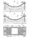
図3(a)に本実施形態の一例としての載置台23の断面模式図を示す。固定機構233として基材1を挟持する機構を用いる場合、図3(a)に示すような装置を使用できる。本実施形態における固定機構233は、基材1の第1の主面側に配置される第1治具2331と、基材1の第2の主面側に配置される第2治具としての台座232と、接続部材(ねじ2332およびナット2333)とを有する。第1治具2331はねじ2332が第1治具2331を貫通できるような貫通孔を有する。
本実施形態において基材1を固定する場合、第2治具としての台座232上に基材1を、さらにねじ2332が貫通孔を通るように基材1上に第1治具2331を載置し、一端が台座232に固定されたねじ2332の他端側からナット2333を螺合する。これにより第1治具2331と第2治具としての台座232とにより基材1を挟持して固定する。この際に、ナット2333を締め付けることにより、基材1を初期形状から評価形状まで変形させつつ固定する。
基材1の初期形状において曲率半径r1の曲率をR1とし、基材1の屈曲部12を評価形状に変形した時の曲率をR2とすると、曲率R1が曲率R2より大きくなることが好ましい。
この際、初期形状において曲率R1となる屈曲部12を有する基材1を、載置面231に接触させ固定機構233を使用することにより、屈曲部12が曲率R2となる評価形状にするのが好ましい。
この際、初期形状において曲率R1となる屈曲部12を有する基材1を、載置面231に接触させ固定機構233を使用することにより、屈曲部12が曲率R2となる評価形状にするのが好ましい。
基材1の初期形状における屈曲部の曲率R1は、特に制限はないが、0.2m-1以上100m-1以下が好ましい(曲率半径r1で100mm以上5000mm以下)。これは屈曲板として高い意匠性が得られるためである。0.5m-1以上80m-1以下がより好ましく、0.8m-1以上50m-1以下がさらに好ましい。
基材1の評価形状における屈曲部の曲率R2は、0m-1以上2m-1以下が好ましい。これは試験や評価の均一性を向上できるためである。0m-1以上1m-1以下がより好ましく、0m-1以上0.3m-1以下がさらに好ましい。
接続部材(ねじ2332およびナット2333)により基材1を変形させる場合、トルクレンチなどにより締め付け圧力を管理してよい。
本発明の耐摩耗性評価装置などの屈曲ガラス評価装置を用いて評価する基材1としては、屈曲部を有するガラス(以下、屈曲ガラスと記載)が好ましい。従来の皮革などで実施されてきた評価方法および評価装置を用いて屈曲ガラスを評価しても、ガラス自体の剛性が高く柔軟性が低いため、例えば耐摩耗性評価における摩擦子を評価面に均質に接触させられなかった。このため、屈曲ガラスの面内では評価部位内でも評価条件が異なるといった状況が発生し、バラつきの大きな評価結果となっていた。本発明の屈曲ガラス評価装置を使用することにより屈曲ガラスの屈曲部における曲率を変形でき、評価部位内においてもほぼ同じ評価条件で評価され、バラつきの少ない評価結果が得られる。
図3(b)に図3(a)の載置台を使用して基材1を固定した際の断面模式図を示す。図3(b)に示すように基材1の第2の主面1bが、台座232の載置面231に一致することが好ましい。これにより基材1の第2の主面1bが強固に固定され正確な評価を実施しやすくなる。また基材1の第1の主面1aが、第1治具2331の接触面の形状と一致することがさらに好ましい。これにより基材1の第1の主面1aも固定されより正確な評価を実施できる。
載置面231の曲率R3の屈曲部の曲率半径をr3とし、変形後の評価形状における基材のうち対応する曲率R2の屈曲部の曲率半径をr2とし、基材の厚さをtとすると、|r3-r2|=tとなることが好ましい。
これにより載置された基材1の載置面231との接触面を第2の主面1bとすると、載置面231と基材1の第2の主面1bとが広範囲にわたって接触でき、基材1が安定して支持される。これにより、耐摩耗性評価において摩擦子241の基材1への接触圧力が均一化され、正確な評価を実施できる。
これにより載置された基材1の載置面231との接触面を第2の主面1bとすると、載置面231と基材1の第2の主面1bとが広範囲にわたって接触でき、基材1が安定して支持される。これにより、耐摩耗性評価において摩擦子241の基材1への接触圧力が均一化され、正確な評価を実施できる。
図3(c)に図3(b)の載置台の上面視図を示す。第1治具2331は本体2331aと開口部2331bとを備える。これにより基材1の第1の主面1aが露出するため、基材を評価形状に変形させつつ、第1の主面の評価を実施できる。
第1治具2331、第2治具、台座232の材質は、特に制限はない。金属や樹脂、セラミックなどを使用できる。基材1と接する部位だけゴムやウレタンのような樹脂を配置してもよい。これにより基材1への擦り傷発生を抑制しつつ強固に固定できる。
載置台23は図4(a)のように、第1治具2331または第2治具としての台座232のいずれかの形状だけが基材1と接触する形状となるようにしてもよい。また、載置台23は図4(b)のように、固定機構233として台座232に真空孔2334を備え、吸着固定できるようにしてよい。この際には第1治具2331がなくてもよい。この場合も、載置面231の曲率R3の屈曲部の曲率半径をr3とし、変形後の評価形状における基材のうち対応する曲率R2の屈曲部の曲率半径をr2とし、基材の厚さをtとすると、|r3-r2|=tとなることが好ましい。
[耐摩耗性評価方法]
前述の耐摩耗性評価装置を使用した基材の評価方法は以下の通りである。本発明の基材の評価方法は、屈曲部12を有する第1の主面1aと第2の主面1bと端面とを備えた基材1について、屈曲部12の曲率を変化させるように基材1を変形し、基材1の第1の主面1aを評価する。
前述の耐摩耗性評価装置を使用した基材の評価方法は以下の通りである。本発明の基材の評価方法は、屈曲部12を有する第1の主面1aと第2の主面1bと端面とを備えた基材1について、屈曲部12の曲率を変化させるように基材1を変形し、基材1の第1の主面1aを評価する。
基材を変形する際に、初期形状における基材1の屈曲部における曲率R1とし、基材1の屈曲部12を評価形状に変形した時の曲率をR2とすると、曲率R1が曲率R2より大きくなることが好ましい。
本実施態様によれば、初期形状で曲率がR1の屈曲部を有する基材を、R1より小さい曲率R2となるように評価形状に変形するため、平板状基材を評価する際の試験方法や計測方法を利用しやすくなり、均質かつ正確な評価を実施できる。
基材の変形は、基材1の第1の主面1aと第2の主面1bとを挟持して変形してもよく、第2の主面1bに負圧を供給してもよく、基材1を変形できる機構を有すれば特に制限はない。基材1を変形でき、そのまま固定できる機構が好ましい。
基材を変形する際に、基材1の第1の主面1aの圧力P1(Pa)と第2の主面2bの圧力P2(Pa)とに差を設けることが好ましく、圧力P1が圧力P2より大きくなることがより好ましい。
本実施態様によれば、圧力差により簡単に基材1を評価形状に変形できる。
本実施態様によれば、圧力差により簡単に基材1を評価形状に変形できる。
基材1の第1の主面1aと第2の主面1bとの圧力差を形成する方法として、第2の主面1bを台座232に載置し、第2の主面1b側に負圧を供給することが好ましい。
本実施態様によれば、基材1の第2の主面1b側のみに負圧を供給できる設備を設ければよく、簡易に基材を評価形状に変形できる。
本実施態様によれば、基材1の第2の主面1b側のみに負圧を供給できる設備を設ければよく、簡易に基材を評価形状に変形できる。
基材評価の一例として、図1に示すような耐摩耗性評価装置を使用し、評価形状とした基材1の耐摩耗性評価を実施する。この際に、基材1の第1の主面1aを評価することが好ましい。
また基材1の第1の主面1aには、評価を実施したい場所や範囲が明確となるようにマーキングしてもよい。これにより、評価途中で測定などのために基材1を台座232から取り外しても、再度元の位置に基材1を固定でき評価を再開できる。
また基材1の第1の主面1aには、評価を実施したい場所や範囲が明確となるようにマーキングしてもよい。これにより、評価途中で測定などのために基材1を台座232から取り外しても、再度元の位置に基材1を固定でき評価を再開できる。
基材評価工程において、耐摩耗性評価装置2を使用し、耐摩耗性を評価する方法は以下の通りである。
最初に、評価したい基材1を準備し、台座232に初期形状から評価形状に変形させ、台座232に基材1を固定する。この基材1を固定した台座232を耐摩耗性評価装置2の水平往復運動装置22に接続する。
最初に、評価したい基材1を準備し、台座232に初期形状から評価形状に変形させ、台座232に基材1を固定する。この基材1を固定した台座232を耐摩耗性評価装置2の水平往復運動装置22に接続する。
続いて耐摩耗性評価装置2に摩擦治具24を取り付ける。消しゴムや金巾などの素材を所望の形状に加工して摩擦子241とし、固定具242に取り付け、これを調整棒243の一端に取り付ける。基材1の第1の主面1aと摩擦子241との距離を所望の距離となるように、調整棒243を調節する。
摩擦子241の大きさは、評価面積などに応じて調整すればよく特に制限はないが、上面視で直径10mmの円形、縦20mm×横10mmの矩形など適宜選択できる。また、耐摩耗性評価中に、摩擦子241を交換してもよい。これは摩擦子241が基材1との接触により劣化することがあり、正確な評価を実施するため交換が必要となる。
耐摩耗性評価装置2に耐摩耗性評価条件により、調整棒243の他端側から評価用おもり244を載置してもよい。評価用おもりは複数個使用でき、評価条件となるようにすればよい。評価条件としては特に制限はないが、評価用おもりの質量は0.5kg~5kgが好ましい。
また予め水平調整棒246の水平調整おもり245により、腕252の傾きを調整してから評価用おもり244を載置してもよい。
また予め水平調整棒246の水平調整おもり245により、腕252の傾きを調整してから評価用おもり244を載置してもよい。
以上より、台座232に固定した基材1の第1の主面1aに、所望の負荷がかかるように摩擦子241を接触させ、評価開始状態とできる。
ここで摩擦子241と基材1とが所望の速度で評価できるように、速度調整スイッチにより調整する。また摩擦子241と基材1とが所望の摺動回数で停止できるように、カウンタ28で設定する。この状態で電源スイッチ27をONとして、評価を開始する。
以上より、所望の条件にて耐摩耗性評価を実施することにより、基材1の第1の主面1aについて均質かつ正確な耐摩耗性を評価できる。
基材1の耐摩耗性を評価する方法としては、目視、顕微鏡観察、触感など特に制限はないが、定量評価しやすい観点から、いわゆる濡れ性を評価できる対液体界面評価が好ましい。初期形状で屈曲部を有する基材を評価する際に、屈曲部を変形して評価形状とするため、液体の滴下位置の違いなどで生じる誤差を小さくでき均質かつ正確な計測を実施できる。
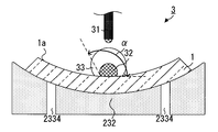
図5に対液体界面評価時の側面視図を示す。耐摩耗性評価後の基材1を台座232に固定させた状態で対液体界面評価装置を準備する。
対液体界面評価装置3は試験液体を蓄えたシリンジ31とカメラ33とを備え、シリンジ31から基材1の第1の主面1aに試験液体を滴下して液滴32を形成する。カメラ33により液滴32を観察し、液滴32と第1の主面1aとで形成される角度αを算出する。この角度を耐摩耗性評価前後で比較し、間接的に基材1の耐摩耗性を評価できる。角度αは基材1の形状に大きく影響をうけるため、上述した耐摩耗性評価方法により基材1の第1の主面1aを平坦化できることにより、角度αへの影響を最小限にでき、バラつきを低減できる。
対液体界面評価装置3は試験液体を蓄えたシリンジ31とカメラ33とを備え、シリンジ31から基材1の第1の主面1aに試験液体を滴下して液滴32を形成する。カメラ33により液滴32を観察し、液滴32と第1の主面1aとで形成される角度αを算出する。この角度を耐摩耗性評価前後で比較し、間接的に基材1の耐摩耗性を評価できる。角度αは基材1の形状に大きく影響をうけるため、上述した耐摩耗性評価方法により基材1の第1の主面1aを平坦化できることにより、角度αへの影響を最小限にでき、バラつきを低減できる。
試験液体は純水、グリセリンなどの有機液体など目的に応じて使用できる。なお測定結果の角度αについて、基材1の第1の主面1aの曲率に応じて値の補正を行ってもよい。
(評価)
評価については、上述の耐摩耗性評価や対液体界面評価に限らない。例えば、耐薬品性評価を実施する際に、試験薬液を安定的に基材上に保持でき、正確な評価を実施できる。また光学特性評価を実施する際に、基材の屈曲による光学的影響を最小限にでき、正確な評価を実施できる。表面形状評価を実施する際に、基材の屈曲による形状歪みを低減でき、正確に表面形状を測定でき評価できる。
評価については、上述の耐摩耗性評価や対液体界面評価に限らない。例えば、耐薬品性評価を実施する際に、試験薬液を安定的に基材上に保持でき、正確な評価を実施できる。また光学特性評価を実施する際に、基材の屈曲による光学的影響を最小限にでき、正確な評価を実施できる。表面形状評価を実施する際に、基材の屈曲による形状歪みを低減でき、正確に表面形状を測定でき評価できる。
耐摩耗性評価については、摩擦子による耐擦傷性試験に限らず、鉛筆硬度試験、クロスカット剥離性試験などを実施できる。
光学特性評価については、透過率測定、反射率測定、ヘイズ測定、色度測定、光学濃度測定、解像度指標測定、ギラツキ指標測定、反射像拡散性指標などを実施できる。これらの光学特性評価を実施できる測定装置は、例えば、測定光を発生する光発生部と、測定光が評価対象に接触した後に得られる情報が加わった情報光を受光する光受光部と、を備える。光学特性評価は、情報が加わった情報光の量と質が重要となる。屈曲部を有する基材を評価した場合に、光発生部と基材との距離が一定にならないことや、基材の屈曲部による光発生部や光受光部と基材との間隙から外光が混入する可能性があることから、情報光にバラつきや正確性が失われることがある。
上述の評価方法、評価装置により、屈曲部を備える基材を平坦化できるため、光発生部と基材との距離を一定範囲にでき、さらに光発生部や光受光部との間隙がなくなる。これにより外光の混入を抑制できるなどから、正確に光学特性評価を実施できる。
<変形例>
なお、本発明は上記実施形態にのみ限定されるものではなく、本発明の要旨を逸脱しない範囲内で種々の改良ならびに設計の変更等が可能であり、その他、本発明の実施の際の具体的な手順、及び構造等は本発明の目的を達成できる範囲で他の構造等としてもよい。
なお、本発明は上記実施形態にのみ限定されるものではなく、本発明の要旨を逸脱しない範囲内で種々の改良ならびに設計の変更等が可能であり、その他、本発明の実施の際の具体的な手順、及び構造等は本発明の目的を達成できる範囲で他の構造等としてもよい。
(基材)
基材として、ガラス、シリコン等が挙げられる。ガラスとして、無機ガラスや有機ガラスが挙げられる。有機ガラスとして、ポリカーボネート、ポリメタクリル酸メチル等が挙げられる。
基材として、ガラス、シリコン等が挙げられる。ガラスとして、無機ガラスや有機ガラスが挙げられる。有機ガラスとして、ポリカーボネート、ポリメタクリル酸メチル等が挙げられる。
カバー部材の部材が無機ガラスである場合、少なくとも1つの主面が強化処理されていることが好ましい。これにより必要な機械的耐久性及び耐擦傷性を確保できる。強化処理としては物理強化処理、化学強化処理ともに使用できるが、比較的に薄いガラスでも強化処理できる点から化学強化処理が好ましい。
基材のヤング率として、50GPa以上が好ましく、60GPa以上がより好ましく、70GPa以上がさらに好ましい。これは屈曲部を備えた基材を変形させ、第1の主面1aの非破壊評価を実施する際に、基材を破損させずに評価形状まで変形でき、評価後も基材を元の形状に戻せる。基材のヤング率の上限値は特に制限はないが、評価の観点から、例えば200GPa以下が好ましく、150GPa以下がより好ましい。なお、基材のヤング率は、日本工業規格JIS R 1602 (1995)に基づき、超音波法を用いて、縦20mm×横20mm×厚さ10mmの試験片について測定し算出できる。
基材のビッカース硬度Hvとして、400以上が好ましく、500以上が好ましい。基材を変形する際に例えば基材が第1治具を用いた場合、第1治具との接触により生じ得る基材の擦傷や破損を抑制できる。これにより基材の評価以外の擦傷などを抑制でき、基材評価の正確性を向上できる。基材のビッカース硬度の上限値は特に制限はないが、例えば1200以下が好ましく、1000以下がより好ましい。なお、本実施形態の基材のビッカース硬度は、たとえば日本工業規格JIS Z 2244 (2009)に記載する、ビッカース硬さ試験により測定できる。
(加工)
基材の少なくとも一方の主面を研削・研磨加工を実施してもよい。
基材の少なくとも一部に孔を形成してもよい。孔は基材を貫通していても、貫通していなくてもよい。
基材の端面は、面取加工などの処理がなされていてもよい。基材がガラスの場合、機械的な研削により一般的にR面取、C面取と呼ばれる加工を行うのが好ましいが、エッチングなどで加工を行ってもよく、特に限定されない。
基材について必要な個所に、各種表面処理層や印刷層を形成する工程を実施してもよい。表面処理層としては、反射防止処理層、防汚処理層などが挙げられ、これらを併用してもよい。
基材の少なくとも一方の主面を研削・研磨加工を実施してもよい。
基材の少なくとも一部に孔を形成してもよい。孔は基材を貫通していても、貫通していなくてもよい。
基材の端面は、面取加工などの処理がなされていてもよい。基材がガラスの場合、機械的な研削により一般的にR面取、C面取と呼ばれる加工を行うのが好ましいが、エッチングなどで加工を行ってもよく、特に限定されない。
基材について必要な個所に、各種表面処理層や印刷層を形成する工程を実施してもよい。表面処理層としては、反射防止処理層、防汚処理層などが挙げられ、これらを併用してもよい。
本出願は、2016年11月25日出願の日本特許出願2016-229439に基づくものであり、その内容はここに参照として取り込まれる。
1 基材
1a 第1の主面
1b 第2の主面
1c 端面
11 平坦部
12 屈曲部
2 耐摩耗性評価装置
21 本体架台
22 水平往復運動装置
23 載置台
24 摩擦治具
25 支持部材
26 速度調整スイッチ
27 電源スイッチ
28 カウンタ
3 対液体界面評価装置
31 シリンジ
32 液滴
33 カメラ
1a 第1の主面
1b 第2の主面
1c 端面
11 平坦部
12 屈曲部
2 耐摩耗性評価装置
21 本体架台
22 水平往復運動装置
23 載置台
24 摩擦治具
25 支持部材
26 速度調整スイッチ
27 電源スイッチ
28 カウンタ
3 対液体界面評価装置
31 シリンジ
32 液滴
33 カメラ
Claims (15)
- 屈曲部を有する第1の主面と第2の主面と端面とを備えた基材について、前記屈曲部の曲率を変化させるように前記基材を変形し、前記基材の第1の主面の表面状態を評価する、ことを特徴とする基材評価方法。
- 前記基材の屈曲部における曲率R1が、前記基材変形後の屈曲部における曲率R2より大きい、請求項1に記載の基材評価方法。
- 前記基材を変形する際に、第1の主面側の圧力P1と、第2の主面側の圧力P2とに差を設ける、請求項1または2に記載の基材評価方法。
- 前記基材を変形する際に、前記基材の第2の主面を台座に接触させて載置し、第2の主面側に負圧を供給する、請求項1~3のいずれか1項に記載の基材評価方法。
- 前記台座における載置面の屈曲部の曲率半径をr3とし、前記基材変形後の曲率R2の屈曲部における曲率半径をr2とし、前記基材の厚さをtとすると、|r3-r2|=tとなる、請求項4に記載の基材評価方法。
- 前記基材を変形する際に、第1の主面側に配置する第1治具と第2の主面側に配置する第2治具とで前記基材を挟持する、請求項1または2に記載の基材評価方法。
- 第1治具と第2治具との面で前記基材を挟持し、第1治具には、第1の主面が露出する開口部がある、請求項6に記載の基材評価方法。
- 第1治具と第2治具とが接続部材により結合され、前記基材を変形する、請求項6または7に記載の基材評価方法。
- 前記第2治具における載置面の屈曲部の曲率半径をr3とし、前記基材変形後の曲率R2の屈曲部における曲率半径をr2とし、前記基材の厚さをtとすると、|r3-r2|=tとなる、請求項8に記載の基材評価方法。
- 前記表面状態の評価が耐摩耗性評価である、請求項1~9のいずれか一項に記載の基材評価方法。
- 前記表面状態の評価が対液体界面評価である、請求項1~9のいずれか一項に記載の基材評価方法。
- 前記表面状態の評価が光学特性評価である、請求項1~9のいずれか一項に記載の基材評価方法。
- 屈曲部を有する第1の主面と第2の主面と端面とを備えたガラスについて、
前記屈曲部の曲率を変形する固定機構を備えることを特徴とする屈曲ガラス評価装置。 - 前記固定機構が、第1の主面側に配置する第1治具と、第2の主面側に配置する第2治具とを有する、請求項13に記載の屈曲ガラス評価装置。
- 第1治具は、第1の主面が露出する開口部を有する、請求項14に記載の屈曲ガラス評価装置。
Priority Applications (4)
| Application Number | Priority Date | Filing Date | Title |
|---|---|---|---|
| CN201780072458.XA CN109983321B (zh) | 2016-11-25 | 2017-11-20 | 基材评价方法及弯曲玻璃评价装置 |
| JP2018552569A JP6888633B2 (ja) | 2016-11-25 | 2017-11-20 | 基材評価方法および屈曲ガラス評価装置 |
| DE112017005975.5T DE112017005975T5 (de) | 2016-11-25 | 2017-11-20 | Verfahren zur bewertung eines basismaterials und vorrichtung zurbewertung eines gekrümmten glases |
| US16/419,686 US11454579B2 (en) | 2016-11-25 | 2019-05-22 | Base material evaluation method and curved glass evaluation device |
Applications Claiming Priority (2)
| Application Number | Priority Date | Filing Date | Title |
|---|---|---|---|
| JP2016229439 | 2016-11-25 | ||
| JP2016-229439 | 2016-11-25 |
Related Child Applications (1)
| Application Number | Title | Priority Date | Filing Date |
|---|---|---|---|
| US16/419,686 Continuation US11454579B2 (en) | 2016-11-25 | 2019-05-22 | Base material evaluation method and curved glass evaluation device |
Publications (1)
| Publication Number | Publication Date |
|---|---|
| WO2018097099A1 true WO2018097099A1 (ja) | 2018-05-31 |
Family
ID=62195197
Family Applications (1)
| Application Number | Title | Priority Date | Filing Date |
|---|---|---|---|
| PCT/JP2017/041666 Ceased WO2018097099A1 (ja) | 2016-11-25 | 2017-11-20 | 基材評価方法および屈曲ガラス評価装置 |
Country Status (5)
| Country | Link |
|---|---|
| US (1) | US11454579B2 (ja) |
| JP (1) | JP6888633B2 (ja) |
| CN (1) | CN109983321B (ja) |
| DE (1) | DE112017005975T5 (ja) |
| WO (1) | WO2018097099A1 (ja) |
Families Citing this family (4)
| Publication number | Priority date | Publication date | Assignee | Title |
|---|---|---|---|---|
| KR102562270B1 (ko) * | 2021-12-09 | 2023-08-01 | 삼성디스플레이 주식회사 | 유리 강도 평가 장치 및 평가 방법 |
| CN114739794B (zh) * | 2022-04-12 | 2022-11-25 | 扬州大学 | 一种真空玻璃试验机 |
| CN115015015B (zh) * | 2022-06-17 | 2025-05-30 | 京东方科技集团股份有限公司 | 一种耐摩擦测试设备及耐摩擦测试系统 |
| CN116818491B (zh) * | 2023-03-16 | 2024-03-22 | 深圳市中际宏图科技有限公司 | 一种车载摄像头模组镜片检测装置 |
Citations (3)
| Publication number | Priority date | Publication date | Assignee | Title |
|---|---|---|---|---|
| JPS50147683U (ja) * | 1974-05-22 | 1975-12-08 | ||
| JP2007192632A (ja) * | 2006-01-18 | 2007-08-02 | Toyota Boshoku Corp | シート用表皮の耐久試験装置 |
| JP2014085611A (ja) * | 2012-10-26 | 2014-05-12 | Hoya Corp | 眼鏡レンズ耐摩耗試験機 |
Family Cites Families (12)
| Publication number | Priority date | Publication date | Assignee | Title |
|---|---|---|---|---|
| GB1377607A (en) * | 1970-11-27 | 1974-12-18 | Measuring Process Control Ltd | Testing and grading of timber |
| JPS6058528A (ja) * | 1983-09-12 | 1985-04-04 | Mitsubishi Heavy Ind Ltd | 応力腐食割れ試験装置 |
| JPH0271249U (ja) | 1988-11-19 | 1990-05-30 | ||
| JPH1114724A (ja) * | 1997-06-20 | 1999-01-22 | Kawasaki Steel Corp | 金属薄帯表面の磁区構造観察方法 |
| JP2003295131A (ja) | 2002-04-03 | 2003-10-15 | Seiko Epson Corp | 眼鏡レンズの耐擦傷性評価試験方法およびその装置 |
| JP4020004B2 (ja) * | 2003-05-08 | 2007-12-12 | 凸版印刷株式会社 | 薄膜の密着強度評価方法および密着強度評価装置 |
| JP2011209129A (ja) * | 2010-03-30 | 2011-10-20 | Mitsubishi Materials Corp | 発電セルの曲げ試験方法および曲げ試験装置 |
| CN103076248B (zh) * | 2012-12-28 | 2015-09-09 | 潍柴动力股份有限公司 | 一种气缸套活塞环腐蚀磨损试验装置 |
| KR102072061B1 (ko) * | 2013-05-28 | 2020-02-03 | 삼성디스플레이 주식회사 | 기판벤딩장치, 기판벤딩검사장치 및 이를 이용한 기판벤딩검사방법 |
| CN103364296B (zh) * | 2013-07-22 | 2015-11-18 | 嘉兴职业技术学院 | 一种高温摩擦磨损试验机 |
| CN105716944A (zh) * | 2014-11-30 | 2016-06-29 | 中国科学院金属研究所 | 一种弯曲横梁应力腐蚀试验的装置和方法 |
| JP3204577U (ja) | 2016-03-25 | 2016-06-02 | スガ試験機株式会社 | 摩擦試験機 |
-
2017
- 2017-11-20 WO PCT/JP2017/041666 patent/WO2018097099A1/ja not_active Ceased
- 2017-11-20 DE DE112017005975.5T patent/DE112017005975T5/de not_active Withdrawn
- 2017-11-20 JP JP2018552569A patent/JP6888633B2/ja active Active
- 2017-11-20 CN CN201780072458.XA patent/CN109983321B/zh active Active
-
2019
- 2019-05-22 US US16/419,686 patent/US11454579B2/en active Active
Patent Citations (3)
| Publication number | Priority date | Publication date | Assignee | Title |
|---|---|---|---|---|
| JPS50147683U (ja) * | 1974-05-22 | 1975-12-08 | ||
| JP2007192632A (ja) * | 2006-01-18 | 2007-08-02 | Toyota Boshoku Corp | シート用表皮の耐久試験装置 |
| JP2014085611A (ja) * | 2012-10-26 | 2014-05-12 | Hoya Corp | 眼鏡レンズ耐摩耗試験機 |
Also Published As
| Publication number | Publication date |
|---|---|
| CN109983321B (zh) | 2022-06-24 |
| JPWO2018097099A1 (ja) | 2019-10-17 |
| US11454579B2 (en) | 2022-09-27 |
| CN109983321A (zh) | 2019-07-05 |
| DE112017005975T5 (de) | 2019-08-08 |
| JP6888633B2 (ja) | 2021-06-16 |
| US20190271623A1 (en) | 2019-09-05 |
Similar Documents
| Publication | Publication Date | Title |
|---|---|---|
| JP6888633B2 (ja) | 基材評価方法および屈曲ガラス評価装置 | |
| US7637025B2 (en) | Apparatus for measuring thickness of lens | |
| EP2742315B1 (en) | Kinematic fixture for transparent part | |
| US6951392B2 (en) | Lens having at least one lens centration mark and methods of making and using same | |
| CN107450146B (zh) | 一种高精度大口径透镜柔性支撑装置 | |
| US20020148130A1 (en) | Apparatus and method for measuring a shape using multiple probes | |
| JPWO2017150222A1 (ja) | 形状測定装置 | |
| CN106164641A (zh) | 光学元件的测定用夹具、偏心测定装置以及偏心测定方法 | |
| JP4802221B2 (ja) | エリアイメージセンサ支持装置および同センサのアオリ調整方法 | |
| JP2013019782A (ja) | ナノインデンテーション試験装置とそのデータ補正方法 | |
| Garratt et al. | Technology transfer in the development of a nano-topographic instrument | |
| JP2010271098A (ja) | あおり旋回機能付き手動ステージ及びあおり旋回ステージ | |
| JP2009258098A (ja) | レンズ測定装置、レンズ測定方法及びレンズ製造方法 | |
| JP6492702B2 (ja) | 光学素子の測定装置及び測定方法 | |
| JP6274769B2 (ja) | 部品の製造方法、および研磨装置 | |
| JP2015176078A (ja) | 超音波ステージ | |
| JP6207275B2 (ja) | 部品の製造方法、研磨装置、光学部材の製造方法、および型の製造方法 | |
| KR20240060616A (ko) | 재료 제거의 차동 계측을 위한 편향 측정 장치(deflectometry device for differential metrology of material removal) | |
| CN223051353U (zh) | 一种多环境氛围通用原子力显微镜探针夹装置 | |
| TWI375785B (en) | Device for testing eccentricity of a lens and rotary plate of the same | |
| CN100425965C (zh) | 测量镜片偏芯距离的量测治具 | |
| JP2016191653A (ja) | 形状測定機の姿勢調整器 | |
| Aliverti et al. | Mechanical alignment of optical system: CMMs forces and damages on optical elements | |
| JP2013019862A (ja) | 圧子、硬さ試験機、及び硬さ試験方法 | |
| CN210198990U (zh) | 一种显示面板检测装置 |
Legal Events
| Date | Code | Title | Description |
|---|---|---|---|
| 121 | Ep: the epo has been informed by wipo that ep was designated in this application |
Ref document number: 17874258 Country of ref document: EP Kind code of ref document: A1 |
|
| ENP | Entry into the national phase |
Ref document number: 2018552569 Country of ref document: JP Kind code of ref document: A |
|
| 122 | Ep: pct application non-entry in european phase |
Ref document number: 17874258 Country of ref document: EP Kind code of ref document: A1 |