WO2018096918A1 - アンテナ取付部品及びアンテナ装置 - Google Patents
アンテナ取付部品及びアンテナ装置 Download PDFInfo
- Publication number
- WO2018096918A1 WO2018096918A1 PCT/JP2017/040006 JP2017040006W WO2018096918A1 WO 2018096918 A1 WO2018096918 A1 WO 2018096918A1 JP 2017040006 W JP2017040006 W JP 2017040006W WO 2018096918 A1 WO2018096918 A1 WO 2018096918A1
- Authority
- WO
- WIPO (PCT)
- Prior art keywords
- antenna
- base
- mounting
- locking
- hole
- Prior art date
- Legal status (The legal status is an assumption and is not a legal conclusion. Google has not performed a legal analysis and makes no representation as to the accuracy of the status listed.)
- Ceased
Links
Images













Classifications
-
- H—ELECTRICITY
- H01—ELECTRIC ELEMENTS
- H01Q—ANTENNAS, i.e. RADIO AERIALS
- H01Q1/00—Details of, or arrangements associated with, antennas
- H01Q1/27—Adaptation for use in or on movable bodies
- H01Q1/32—Adaptation for use in or on road or rail vehicles
- H01Q1/325—Adaptation for use in or on road or rail vehicles characterised by the location of the antenna on the vehicle
- H01Q1/3275—Adaptation for use in or on road or rail vehicles characterised by the location of the antenna on the vehicle mounted on a horizontal surface of the vehicle, e.g. on roof, hood, trunk
-
- H—ELECTRICITY
- H01—ELECTRIC ELEMENTS
- H01Q—ANTENNAS, i.e. RADIO AERIALS
- H01Q1/00—Details of, or arrangements associated with, antennas
- H01Q1/12—Supports; Mounting means
- H01Q1/1207—Supports; Mounting means for fastening a rigid aerial element
- H01Q1/1214—Supports; Mounting means for fastening a rigid aerial element through a wall
-
- H—ELECTRICITY
- H01—ELECTRIC ELEMENTS
- H01Q—ANTENNAS, i.e. RADIO AERIALS
- H01Q1/00—Details of, or arrangements associated with, antennas
- H01Q1/42—Housings not intimately mechanically associated with radiating elements, e.g. radome
Definitions
- the present invention relates to an antenna mounting component and an antenna device, and more particularly to an antenna mounting component and an antenna device having a structure suitable for mounting on a vehicle body roof.
- an antenna device attached to a vehicle body roof electrically connects an antenna element, an antenna base on which the antenna element is mounted, and a conductor portion of the antenna base and the vehicle body roof when the antenna base is placed on the vehicle body roof.
- the locking member having a locking claw for securing the antenna base and the locking member on the bottom surface of the antenna base so that the locking claw contacts the vehicle body roof on the opposite side of the mounting surface of the antenna base. What comprises the bolt fixed from the side is known (for example, the following patent document 1).
- the protrusion is inserted into the mounting hole of the vehicle body roof together with the locking member in a state where the locking member is integrally provided with a bolt that is loosely screwed to the female screw of the convex portion on the bottom surface of the antenna base.
- the antenna base can be placed on the roof of the vehicle body.
- in-vehicle antenna devices include not only AM / FM radio broadcast receiving antennas but also telephone antennas (3G and 4G), GNSS (global navigation satellite systems: GPS, GLONASS, GALILEO, etc.) (General name) antenna, SDARS (North America satellite digital audio and radio service: generic name including SiriusXM) antenna, DAB (digital audio broadcasting adopted mainly in Europe) antenna, ITS and DSRC intelligent road traffic systems
- 3G and 4G Global navigation satellite systems: GPS, GLONASS, GALILEO, etc.
- SDARS North America satellite digital audio and radio service: generic name including SiriusXM
- DAB digital audio broadcasting adopted mainly in Europe
- ITS and DSRC intelligent road traffic systems There is also a growing demand for built-in antennas. In these cases, a plurality of cables are usually drawn from the antenna base to the outside.
- the locking mechanism in which the opening arm portion and the locking claw are formed is formed on the four sides of the locking member, and when the antenna base is completely attached, the locking mechanism spreads outward.
- the locking mechanism spreads outward.
- the present invention has been made in view of such a situation, and the purpose of the present invention is to mount an antenna base to a mounted body securely and to mount an antenna that can be used to draw out a plurality of cables. It is to provide a component and an antenna device.
- the first aspect of the present invention is an antenna mounting component.
- the antenna mounting component includes a mounting base having a through hole for mounting to the antenna base, First and second locking mechanisms that rise from the first and second outer edge portions of the mounting base that face each other across the through-hole,
- Each of the first and second locking mechanisms includes an opening arm that can be brought into contact with the antenna base at a tip edge, and a claw for contact with a mounted body on which the antenna base is placed,
- Have A locking mechanism for the antenna base does not rise from the third and fourth outer edge portions that connect the first and second outer edge portions of the mounting base to each other.
- the mounting base is substantially square or substantially rectangular, and the first and second locking mechanisms are respectively raised from two opposite sides of the mounting base.
- the mounting base is substantially rectangular and that the first and second locking mechanisms rise from long sides facing each other.
- the claw portion may be positioned near a corner of the mounting base as viewed from a direction perpendicular to the mounting base.
- At least the first locking mechanism may be formed over the entire length of the side.
- At least the claw portions of the first locking mechanism are provided on both sides of the arm portion.
- At least the claw portions of the first locking mechanism are provided at both ends.
- the claw portions provided on both sides of the arm portion may have apexes at the end edges, and the end edges may be inclined so that the apexes are separated from each other.
- the contact portion of the at least one claw portion with the mounted body may be located at a position farthest from the through hole or in the vicinity of the position when viewed from a direction perpendicular to the attachment base portion.
- ribs are formed on the third and fourth outer edges.
- the first and second locking mechanisms may each have a connecting base portion that connects the base end sides of the arm portion and the claw portion.
- a through hole is formed in a boundary portion between the mounting base and the connection base.
- a second aspect of the present invention is an antenna device.
- the antenna device includes the antenna base and the antenna mounting component according to the first aspect attached to the antenna base by a fastening component,
- the cable extending from the antenna base is drawn through the outside of the third outer edge portion of the mounting base as viewed from the direction perpendicular to the mounting base of the antenna mounting component.
- the first and second locking mechanisms rise from the first and second outer edge portions of the mounting base portion having the mounting through-holes facing each other. Since the locking mechanism does not rise from the third and fourth outer edge portions that communicate with each other, it is possible to easily pull out a plurality of cables from the side of the third and fourth outer edge portions. Further, since the first and second locking mechanisms respectively include the opening arm portion and the locking claw portion, the antenna base can be reliably attached to the mounted body.
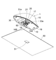
- FIG. 1 is an exploded perspective view illustrating an overall configuration of an antenna device including an antenna attachment component according to a first embodiment of the present invention.
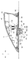
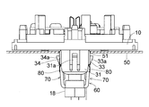
- FIG. 3 is a side cross-sectional view showing the antenna device placed on a vehicle body roof as a mounted body and in a temporarily fixed state.
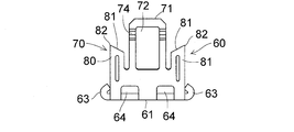
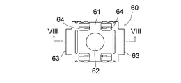
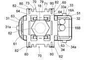
- the front view of the said antenna attachment component The same side view.
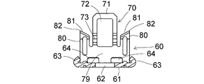
- FIG. VIII-VIII sectional view of FIG. The perspective view which shows the bottom face side of the said antenna apparatus, and the attachment hole of a vehicle body roof.
- FIG. 3 is a perspective view of a main part of the antenna device in a temporarily fixed state (before tightening a bolt as a fastening part).
- the perspective view of the fixed state which fastened the bolt as a fastening component similarly.
- the principal part of the said antenna apparatus Comprising: The sectional side view of a temporary fix
- the side sectional view of a fixed state similarly.
- the principal part of the said antenna apparatus Comprising: The side view of a temporarily fixed state.
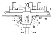
- the side view of a fixed state similarly.
- the front view of a fixed state similarly.
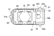
- the principal part of the said antenna apparatus Comprising: The top view of a temporarily fixed state.
- the top view of a fixed state similarly.
- Embodiment 1 An antenna mounting component and an antenna apparatus using the antenna mounting component according to Embodiment 1 of the present invention will be described with reference to FIGS.
- the antenna device 1 sandwiches an antenna base 10 having a conductive metal portion, a conductive metal bolt 18 as a fastening part, and a vehicle body roof 50 as a mounted body together with the antenna base 10.
- a conductor metal antenna mounting part 60 is provided which is attached to the antenna base 10 by a conductor metal bolt 18.
- FIG. 3 illustrates the front-rear direction and the vertical direction of the antenna device 1.
- the antenna base 10 is a combined structure of a metal base portion 20 formed of a conductive metal and a resin base portion 30 provided integrally therewith.
- a capacitive element 41 and a coil element 42 that constitute an AM / FM radio broadcast receiving antenna 40 are provided, and an antenna substrate 43 on which an amplifier circuit and the like are mounted is fixed.
- a case 15 is provided on the upper side of the antenna base 10 so as to accommodate them.
- telephone antennas, GNSS antennas, SDARS antennas, DAB antennas, intelligent road traffic system antennas, DTV antennas, etc. are incorporated inside the case 15 and are necessary. Accordingly, an amplifier circuit for the antenna is further mounted on the antenna substrate 43 or another antenna substrate (not shown). As a result, as shown in FIGS.
- the plurality of coaxial cables 16 ⁇ / b> A and 16 ⁇ / b> B connected to the antenna substrate 43 are drawn from the bottom surface of the antenna base 10.
- the coaxial cable 16A outputs a reception signal of the AM / FM radio broadcast receiving antenna 40
- the coaxial cable 16B outputs a reception signal of other antennas. If another antenna substrate (not shown) is provided, more coaxial cables are drawn from the bottom surface of the antenna base 10.
- a convex portion 21 having a substantially rectangular (substantially prismatic) planar shape is provided with a conductive metal.
- the convex portion 21 protrudes downward from the bottom surface of the metal base portion 20, and two long sides of the convex portion 21 having a substantially rectangular planar shape are parallel to the longitudinal direction of the antenna base 10.
- the vertical direction (antenna base bottom surface) with a predetermined width at an intermediate position along the long side.
- the locking concave grooves 22 are formed in a direction perpendicular to the vertical direction.
- the locking groove 22 is deeply formed up to the base of the protrusion 21. Further, on both sides of the locking concave groove 22, stepped portions 24 that are lowered (dented) stepwise toward the lower end surface 23 of the convex portion 21 are formed. A step surface 25 that is lowered (concave) along the short side from the lower end surface 23 of the convex portion 21 is formed along the two side surfaces (side surfaces on the short side) of the convex portion 21 in the short direction. . A female screw 26 is screwed up and down in the center of the lower end surface 23. The locking groove 22 engages with an opening arm 71 of a conductor metal antenna mounting part 60 described later. The stepped portion 24 is formed so that the reinforcing rib 63 does not hit so that the stepped portion 24 does not hinder the movement of the locking claw portion 80.
- a protruding wall portion 31 is formed on the bottom surface of the resin base portion 30 so as to face the side surface on the front side (short side) of the convex portion 21.
- the protruding wall portion 31 integrally has a temporary fixing claw 31a and functions as a first temporary fixing portion.
- the temporary fixing claw 31 a is connected to the lower end portion of the protruding wall portion 31 so as to have flexibility, the thickness increases toward the upper end, and protrudes outward from the outer surface of the protruding wall portion 31.
- a protruding wall portion 32 is formed on the bottom surface of the resin base portion 30 at a position opposite to the protruding wall portion 31 across the convex portion 21.
- the projecting wall portion 32 includes a wall portion 33 along an extension line of one long side of the convex portion 21, and a wall portion 34 along an extension line of the other long side of the convex portion 21.
- the wall portion 33 integrally has a temporary fixing claw 33a and functions as a second temporary fixing portion
- the wall portion 34 integrally has a temporary fixing claw 34a and functions as a third temporary fixing portion.
- the temporary pawls 33a and 34a are connected to the lower end portions of the wall portions 33 and 34 so as to be flexible, the thickness increases toward the upper end, and the outer side surfaces of the wall portions 33 and 34 are outside. It protrudes.
- the coaxial cables 16 ⁇ / b> A and 16 ⁇ / b> B are drawn out through the inside of the protruding wall portion 32, that is, between the wall portions 33 and 34.
- the convex portion 21 and the protruding wall portions 31 and 32 are portions that are fitted into the mounting holes 51 of the vehicle body roof 50 from above (inserted portions).
- the temporary fixing claws 31a, 33a, and 34a formed on the protruding wall portions 31 and 32 are engaged with the lower surface of the mounting hole 51 of the vehicle body roof 50 to perform a temporary fixing function.
- the conductor metal antenna mounting component 60 is opposed to a substantially rectangular mounting base 61 having a mounting through hole 62 in the center with respect to the antenna base 10 with the mounting through hole 62 interposed therebetween.
- a pair of (first and second) locking mechanisms 70 respectively rising from two long sides (outer edge portions in the longitudinal direction) of the mounting base portion 61 to be mounted.
- the pair of locking mechanisms 70 are formed symmetrically with respect to a plane that passes through the center line between the two long sides of the mounting base 61 and is perpendicular to the mounting base 61.
- Each locking mechanism 70 is formed over substantially the entire length of the long side.
- the opening arm 71 rises from the vicinity of the center of the long side of the mounting base 61. At the tip of the opening arm 71, there is a tip that fits into the locking groove 22 formed along the longitudinal direction of the protrusion 21, and the width of the tip is larger than the width of the locking groove 22. Is also formed with a slightly shorter width.
- the opening arm portion 71 has a substantially rectangular hole 72 having a longitudinal direction in the vertical direction from the distal end portion toward the mounting base portion 61, and is pressed against the antenna base 10 side by tightening the conductor metal bolt 18. Easy to bend. Further, on both sides of the opening hole 72 of the opening arm 71, a bending groove for reducing the thickness is formed on the inner surface side, and the first joint portion 73 is provided on the mounting base 61 side, and further on the outer surface side. The bending direction is defined by forming a bending groove for reducing the thickness and providing the second joint portion 74 on the distal end side.
- the opening arm portion 71 is connected to the first joint portion 73 and the second joint portion. In the part 74, it bend
- the locking claw portions 80 are provided on both sides of the opening arm portion 71, and the proximal end sides of the opening arm portion 71 and the locking claw portion 80 are connected by the connecting base portion 79.
- the connecting base 79 and the locking claw 80 integrated with the base open to the outside. Note that the width of the long side and the short side of the mounting base 61 is larger than the width of the head of the conductor metal bolt 18 or the diameter of the circumscribed circle.
- the locking claw portions 80 are respectively provided at both ends of the locking mechanism 70 that are located on both sides of the opening arm portion 71.
- the latching claw portion 80 is positioned near the corner of the mounting base 61 when viewed from a direction perpendicular to the substantially rectangular mounting base 61.
- the locking claw portion 80 in each locking mechanism 70 has a vertex 82 at the tip edge 81, and the positional relationship in which the vertexes 82 are separated from each other, that is, away from both sides of the locking mechanism 70.
- the leading edge 81 is inclined so as to be in a positional relationship. As shown in FIG.
- each locking claw portion 80 (which becomes a contact portion with the vehicle body roof 50) is attached in the state of being in contact with the vehicle body roof 50 as viewed from the direction perpendicular to the attachment base 61. It is at a position farthest from the through hole 62 for use or in the vicinity of the position.
- Each latching claw portion 80 is formed with a rib 88 protruding inward by press work or the like for reinforcement (so as not to bend).
- a locking mechanism is not provided on two sides (short sides: outer edges in the short direction) different from the two sides (long sides) on which the pair of locking mechanisms 70 of the mounting base 61 rises.
- the reinforcing rib 63 is formed over the entire length of each short side.
- the reinforcing rib 63 is formed with a small radius of curvature toward the top of the mounting base 61 (the same as the direction in which the locking mechanism 70 rises), and prevents the mounting base 61 from bending.
- the coaxial cables 16 ⁇ / b> A and 16 ⁇ / b> B are drawn inside the vehicle body roof 50 through the outer side of the rear edge (short side) of the mounting base 61.
- a through-hole 64 is formed at the boundary with 79.
- the through hole 64 is formed at a position near the center in the width direction of the opening arm portion 71 and a position directly below the apex 82 of the locking claw portion 80.
- one through-hole 64 is formed between the center in the width direction of the opening arm 71 and each vertex 82 on both sides of the opening arm 71.
- a conductor metal antenna mounting part 60 is placed on the convex portion 21 which is a conductor metal portion of the antenna base 10 provided with an antenna and covered with the case 15, and the conductor metal bolt 18 is attached to the conductor metal bolt 18 in FIG. And loosely screwed into the female screw 26 (shown in FIG. 2 and the like) on the convex portion 21 side through the mounting through hole 62 of the conductor metal antenna mounting component 60 shown in FIG. Threaded). That is, the conductor metal antenna mounting part 60 and the conductor metal bolt 18 are integrally provided in advance on the antenna base 10 side.
- the convex portion 21 and the projecting wall portions 31 and 32 of the antenna base 10 covered with the conductor metal antenna mounting component 60 are provided. Is fitted into the mounting hole 51 of the vehicle body roof 50.
- the mounting hole 51 is formed in a substantially rectangular shape when viewed from the lower side of the vehicle body roof 50, and includes a protruding wall portion 31 disposed on the front side of the resin base portion 21 and a protruding wall portion disposed on the rear side.
- 32 and the conductor metal antenna attachment component 60 are configured so that the outer shape in plan view is slightly smaller than the attachment hole 51, so that the protruding wall portions 31, 32 and the conductor metal antenna attachment component 60 are attached to the attachment hole 51.
- the temporary fixing claws 31 a, 33 a, 34 a provided on the projecting wall portions 31, 32 open after passing through the mounting hole 51, engage with the peripheral edge of the mounting hole 51, and the antenna base 10 is detached from the vehicle body roof 50.
- rubber packings 17 and 18 provided on the bottom surface of the antenna base 10 shown in FIGS. 2 and 11 are interposed between the bottom surface of the antenna base 10 and the vehicle body roof 50.
- the tip end edge of the opening arm portion 71 abuts on the base side end surface 22a of the locking groove 22 and the conductor metal antenna mounting component 60 moves in the rotational direction. And the upward movement are restricted, so that a force in the compression direction acts on the opening arm 71.
- the second joint portion 74 of the opening arm portion 71 forms a bending groove.
- the first joint portion 73 is moved to the outside of the mounting hole 51 and the first joint portion 73 is also bent to the surface side where the bending groove is formed.
- the connecting base portion 79 of the opening arm portion 71 is widened so that an angle formed with the mounting base portion 61 is increased with the side that is a boundary portion with the mounting base portion 61 as an axis, and the mounting hole 51 of the first joint portion 73 is formed.
- the connecting base 79 and the base are integrated when the first joint 73 moves outside the mounting hole 51.
- the locking claw portion 80 is opened to the outside, and the leading edge of the locking claw portion 80 faces the peripheral edge portion of the mounting hole 51.
- the deformation of the first and second joint portions 73 and 74 proceeds, the locking claw portion 80 is further expanded, and the sharp apex 82 abuts against the back surface of the vehicle body roof 50, Furthermore, it breaks into the painted surface and bites into the metal.
- the conductor metal antenna mounting component 60 is sandwiched between the lower end surface of the convex portion 21 of the antenna base 10 and the head of the conductor metal bolt 18, and the conductor metal bolt 18 cannot be further tightened. It will be in a state and will be in the attachment completion state of the antenna apparatus 1 shown in FIG.13, FIG.15, FIG.17, FIG.19 and FIG.
- the metal base portion 20 to which the ground of the antenna substrate 43 is electrically connected includes the convex portion 21, the conductor metal bolt 18, the conductor metal antenna mounting component 60, and the locking claw portion.
- the vehicle is electrically connected to the vehicle body roof 50 through 80 routes.
- a conductor metal antenna mounting part 60 used for mounting the eaves antenna device 1 to the vehicle body roof 50 (attached body) includes a mounting base 61 having a mounting through hole 62 for the antenna base 10, and a mounting through hole 62. And a pair of (first and second) locking mechanisms 70 that rise from the first and second outer edge portions of the mounting base 61 facing each other. However, since the locking mechanism for the antenna base 10 does not rise from the third and fourth outer edges that connect the first and second outer edges of the mounting base 61 to each other, there is no locking mechanism. 3.
- a plurality of cables can be pulled out from the antenna base 10 through the vehicle body roof 50 using one or both lateral spaces of the fourth and fourth outer edges.
- Each of the latching mechanisms 70 of the conductor metal antenna mounting component 60 includes an opening arm portion 71 that can be brought into contact with the antenna base 10 at the leading edge, and a vehicle body roof 50 on which the antenna base 10 is placed. And a latching claw portion 80 for contact, and the antenna base 10 can be fitted into the mounting hole 51 of the vehicle body roof 50 with the conductor metal antenna mounting part 60 and the conductor metal bolt 18 provided in advance. Is possible. Then, by tightening the conductor metal bolt 18 after fitting, the latching claw portion 80 can be opened so as to face the peripheral edge portion of the mounting hole 51 by utilizing the deformation of the opening arm portion 71, and further made of conductor metal.
- the locking claws 80 can be bitten into the back surface of the vehicle body roof 50. For this reason, after the antenna base 10 is placed on the vehicle body roof 50, it is not necessary to attach the conductor metal antenna mounting component 60 with the conductor metal bolt 18 from the lower side of the vehicle body roof 50. Workability is good.
- the locking claws 80 provided on both sides of the arm portion 71 for opening the heel have apexes 82 at the end edges 81, and the end edges 81 are inclined so that the apexes 82 are separated from each other. For this reason, the contact portion of the locking claw portion 80 with the vehicle body roof 50 is located at a position farthest from the mounting through-hole 62 or in the vicinity of the position when viewed from the direction perpendicular to the mounting base 61. In this respect as well, the mounting strength can be increased.
- the reinforcing rib 63 is formed over the entire length of the third and fourth outer edge portions (a pair of short sides) where the locking mechanism of the eaves mounting base portion 61 is not raised, bending of the mounting base portion 61 can be prevented. In addition, it is possible to prevent a mounting failure due to the bending of the mounting base 61.
- Each of the hook locking mechanisms 70 is connected by a connecting base 79 that connects the base end sides of the opening arm 71 and the locking claw 80, and at the boundary between the mounting base 61 and the connecting base 79. Since the through hole 64 is formed at an appropriate position, the locking mechanism 70 can be smoothly opened by the tightening operation of the conductor metal bolt 18.
- the convex portion 21 and the protruding wall portions 31 and 32 provided on the eaves antenna base 10 are portions (inserted portions) that are fitted into the mounting holes 51 of the vehicle body roof 50 from above, and the protruding wall portions 31 and 32.
- the antenna base 10 can be temporarily fixed to the vehicle body roof 50, and the mounting workability of the antenna device 1 can be improved.
- FIG. 22 shows a conductor metal antenna mounting component 60A according to Embodiment 2 of the present invention.
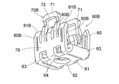
- the locking claw portion 80A of one locking mechanism 70A is greatly different from the first embodiment in that the tip edge 81A has a rounded curved shape.
- Other configurations are substantially the same as those of the first embodiment.
- the locking claw portion 80A of one locking mechanism 70A abuts without breaking the painted surface of the back surface of the vehicle body roof 50.
- all the locking claws are configured to break the painted surface of the vehicle roof and come into contact with the bare metal.
- the locking claws of one locking mechanism Even if the 80A is simply configured to abut on the painted surface of the vehicle roof, the effect similar to that of the first embodiment can be obtained.
- FIG. 23 shows a conductor metal antenna mounting part 60B according to Embodiment 3 of the present invention.
- the tip edge 81B of the locking claw portion 80B of one locking mechanism 70B has a flat shape without inclination instead of the tip edge 81A having a round and curved shape in the second embodiment.
- Other configurations are the same as those of the second embodiment.
- the leading edge 80B abuts without breaking the painted surface on the back surface of the vehicle body roof 50, and the same operations and effects as in the second embodiment are exhibited.
- the leading edges of the two locking claws are formed so as to contact the metal base of the vehicle roof 50, but the leading edge of at least one locking claw is the vehicle roof 50. As long as it is in contact with the base metal, the tip portions of all the remaining locking claws may be in contact with the painted surface without contacting the base metal.
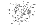
- FIG. 24 shows a conductor metal antenna mounting part 60C according to Embodiment 4 of the present invention.
- one locking mechanism 70 ⁇ / b> C has no locking claw portions on both sides of the opening arm portion 71, and forms one locking claw portion 80 ⁇ / b> C inside the punched hole 72. is doing.
- the total number of locking claws is three.
- Other configurations are the same as those of the first embodiment. Thereby, since the latching claw part is in contact with the back surface of the vehicle roof 50 at three locations, sufficient mounting strength can be ensured although the mounting strength is inferior to the four locations of the first embodiment.
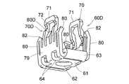
- FIG. 25 shows a conductor metal antenna mounting component 60D according to Embodiment 5 of the present invention.
- one locking mechanism 70 ⁇ / b> D forms an additional locking claw portion 80 ⁇ / b> D inside the punched hole 72 of the opening arm portion 71.
- the total number of locking claws is five.
- Other configurations are the same as those of the first embodiment. Thereby, since the latching claw part is in contact with the back surface of the vehicle roof 50 at five places, it is possible to secure a further sufficient mounting strength as compared with the four places in the first embodiment.
- FIG. 26 shows a conductor metal antenna mounting part 60E according to Embodiment 6 of the present invention.
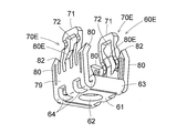
- each of the pair of locking mechanisms 70 ⁇ / b> E additionally has a locking claw portion 80 ⁇ / b> E inside the opening hole 72 of the opening arm portion 71.
- the total number of locking claws is six.
- Other configurations are the same as those of the first embodiment.
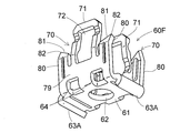
- FIG. 27 shows a conductor metal antenna mounting part 60F according to Embodiment 7 of the present invention.
- the reinforcing rib 63A is folded at a small radius of curvature downward (opposite to the rising direction of the locking mechanism 70) over the entire length of the outer edge (short side) where the locking mechanism 70 of the mounting base 61 does not rise. It is bent.
- Other configurations are the same as those of the first embodiment.
- FIG. 28 shows a conductor metal antenna mounting part 60G in the eighth embodiment of the present invention.
- the reinforcing rib 63B faces upward with respect to the mounting base 61 over the entire length of the outer edge (short side) where the locking mechanism 70 of the mounting base 61 does not stand up (the rising of the locking mechanism 70). (Same direction as raising).
- Other configurations are the same as those of the first embodiment.
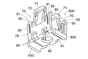
- FIG. 29 shows a conductor metal antenna mounting part 60H according to the ninth embodiment of the present invention.
- the reinforcing rib 63C is bent downward so as to form approximately 90 ° with respect to the mounting base 61 over the entire length of the outer edge (short side) where the locking mechanism 70 of the mounting base 61 does not stand up.
- Other configurations are the same as those of the first embodiment.
- FIG. 30 shows a conductor metal antenna mounting part 60I according to the tenth embodiment of the present invention.
- a groove 69 is formed at the boundary between the attachment base 61 and the connection base 79 of the locking mechanism 70, and the connection base 79 bends with respect to the attachment base 61. It is configured to be easy. Other configurations are the same as those of the first embodiment.
- the antenna base 10 is a combined structure of the metal base portion 20 and the resin base portion 30 provided integrally therewith, but the entire antenna base 10 is formed of a conductive metal. May be.
- the convex portion 21 protruding from the bottom surface of the antenna base 10 has a substantially rectangular (substantially prismatic) planar shape, but if it has a function of preventing rotation of the conductor metal antenna mounting part, it is a substantially cylindrical convex portion. Also good.
- the through hole 64 is formed at the boundary between the attachment base 61 and the connection base 79, but may be formed near the boundary between the attachment base 61 or the connection base 79. Further, instead of the through hole 64, a portion corresponding to the through hole 64 may be formed thin.
- the locking claw portion 80A of one locking mechanism 70A has a shape in which the tip edge 81A is rounded and curved.
- both of the locking mechanisms are the rounded curved tip edge 81A, the end face of the tip edge 81A does not contact the body roof, but the edge of the tip edge 81A ( It becomes possible to take an electrical contact by hitting the corner.
- the locking claw portion 80B of one locking mechanism 70B of the pair of locking mechanisms of the conductor metal antenna mounting part 60B has a flat shape with the tip edge 81B not inclined. However, even when both of the locking mechanisms are the flat leading edge 81B having no inclination, the end surface of the leading edge 81B does not abut against the roof of the vehicle body. It is possible to make electrical contact by hitting the edge (corner) of the end face.
- the female base is screwed on the bottom surface of the antenna base, and the metal clad bolt is tightened to open the locking claw.
- the metal clad bolt may be configured to open.
- the antennas mounted on the antenna base 10 can be appropriately combined depending on the application, and further, electronic devices such as camera units can be mounted.
- Antenna apparatus 10 Antenna base 16A, 16B Coaxial cable 18 Conductor metal volt
Landscapes
- Engineering & Computer Science (AREA)
- Remote Sensing (AREA)
- Support Of Aerials (AREA)
Abstract
アンテナベースの被装着体への取り付けを確実に行うことができ、かつ複数本のケーブルの引き出しにも対応可能なアンテナ取付部品及びアンテナ装置を提供する。 アンテナベース10と、導体金属製ボルト18によってアンテナベース10に取り付けられる導体金属製アンテナ取付部品60とを備える。導体金属製アンテナ取付部品60はアンテナベース10に対する取付用貫通孔62を有する取付基部61と、その一対の長辺からそれぞれ立ち上がる係止機構70とを備えるが、取付基部61の短辺からは係止機構が立ち上がらない構成である。アンテナベース10から伸びるケーブル16A,16Bは、係止機構が立ち上がらない取付基部61の短辺の外側から引き出されている。
Description
本発明は、アンテナ取付部品及びアンテナ装置に係り、とくに車体ルーフに取り付けるのに適した構造を持つアンテナ取付部品及びアンテナ装置に関する。
従来、車体ルーフに取り付けられるアンテナ装置は、アンテナエレメントと、これを搭載したアンテナベースと、アンテナベースが車体ルーフに載置されたときにアンテナベースの導体部と車体ルーフとを電気的に接続しかつアンテナベースの固定を確実にするための係止爪を有する係止部材と、アンテナベースの載置面の反対側の車体ルーフに係止爪が接触するように係止部材をアンテナベースの底面側から固定するボルトとを具備するものが知られている(例えば下記特許文献1)。
特許文献1の構造においては、アンテナベース底面の凸部の雌ネジに緩く螺合したボルトで係止部材を一体的に設けた状態で、係止部材と共に凸部を車体ルーフの取付穴に挿入でき(アンテナベースを車体ルーフ上に載置でき)、その後、ボルトを締め付けることで係止部材の四辺に形成された係止機構(開口用腕部及び係止爪)を取付穴よりも外側に拡げて車体ルーフ内面(アンテナベース載置面の反対面)に係止爪を当接させるようにしている。
近年、車載用のアンテナ装置においては、AM/FMラジオ放送受信用アンテナだけでなく、電話用アンテナ(3Gや4G)や、GNSS(全世界的航法衛星システム:GPSやGLONASSやGALILEOなどを含めた総称)用アンテナ、SDARS(北米衛星デジタルオーディオ・ラジオサービス:SiriusXMを含めた総称)用アンテナ、DAB(欧州圏を中心に採用されているデジタル音声放送)用アンテナ、ITSやDSRCといった高度道路交通システム用アンテナの組込み等も要望されるようになってきている。これらの場合には、アンテナベースから外部に引き出されるケーブルは通常複数本になる。
特許文献1の場合、開口用腕部及び係止爪が形成された係止機構が係止部材の四辺に形成されていて、アンテナベースの取付完了状態では、係止機構が外側に拡がるため、アンテナベース底面から複数本のケーブルを引き出す場合、車体ルーフ側の取付穴の形状寸法によっては複数本のケーブルを引き出す空間を係止機構の側方に確保することが困難になる。
本発明はこうした状況を認識してなされたものであり、その目的は、アンテナベースの被装着体への取り付けを確実に行うことができ、かつ複数本のケーブルの引き出しにも対応可能なアンテナ取付部品及びアンテナ装置を提供することにある。
本発明の第1の態様はアンテナ取付部品である。このアンテナ取付部品は、アンテナベースに対する取付用の貫通孔を有する取付基部と、
前記貫通孔を挟んで対向する前記取付基部の第1及び第2外縁部からそれぞれ立ち上がる第1及び第2係止機構と、を備え、
前記第1及び第2係止機構はそれぞれ、前記アンテナベースに先端縁で当接可能な開口用の腕部と、前記アンテナベースが載置される被装着体との接触用の爪部と、を有し、
前記取付基部の前記第1及び第2外縁部を相互に連絡する第3及び第4外縁部からは、前記アンテナベースに対する係止機構が立ち上がらないことを特徴とする。
前記貫通孔を挟んで対向する前記取付基部の第1及び第2外縁部からそれぞれ立ち上がる第1及び第2係止機構と、を備え、
前記第1及び第2係止機構はそれぞれ、前記アンテナベースに先端縁で当接可能な開口用の腕部と、前記アンテナベースが載置される被装着体との接触用の爪部と、を有し、
前記取付基部の前記第1及び第2外縁部を相互に連絡する第3及び第4外縁部からは、前記アンテナベースに対する係止機構が立ち上がらないことを特徴とする。
前記取付基部が略正方形又は略長方形であり、前記取付基部の相互に対向する二辺から前記第1及び第2係止機構がそれぞれ立ち上がっているとよい。
前記取付基部が略長方形であり、相互に対向する長辺から前記第1及び第2係止機構がそれぞれ立ち上がっているとよい。
前記爪部は、前記取付基部と垂直な方向から見て前記取付基部の角付近に位置するとよい。
少なくとも第1係止機構は辺の全長に亘って形成されているとよい。
少なくとも前記第1係止機構の前記爪部は、前記腕部の両側にそれぞれ設けられているとよい。
少なくとも前記第1係止機構の前記爪部は、両端部にそれぞれ設けられているとよい。
前記腕部の両側にそれぞれ設けられた前記爪部は先端縁に頂点を有し、前記頂点が互いに離れるように前記先端縁が傾斜しているとよい。
少なくとも1つの前記爪部の前記被装着体への接触部位は、前記取付基部と垂直な方向から見て、前記貫通孔から最も離れた位置若しくは当該位置の近傍にあるとよい。
前記第3及び第4外縁部にリブが形成されているとよい。
前記第1及び第2係止機構はそれぞれ、前記腕部及び前記爪部の基端側同士を連結する連結基部を有するとよい。
前記取付基部と前記連結基部との境界部に透孔が形成されているとよい。
本発明の第2の態様はアンテナ装置である。このアンテナ装置は、前記アンテナベースと、締結部品によって前記アンテナベースに取り付けられた第1の態様に係るアンテナ取付部品と、を備え、
前記アンテナベースから伸びるケーブルが、前記アンテナ取付部品の前記取付基部と垂直な方向から見て、前記取付基部の前記第3外縁部の外側を通って引き出されていることを特徴とする。
前記アンテナベースから伸びるケーブルが、前記アンテナ取付部品の前記取付基部と垂直な方向から見て、前記取付基部の前記第3外縁部の外側を通って引き出されていることを特徴とする。
なお、以上の構成要素の任意の組合せ、本発明の表現を方法やシステムなどの間で変換したものもまた、本発明の態様として有効である。
本発明によれば、取付用の貫通孔を有する取付基部の相互に対向する第1及び第2外縁部から第1及び第2係止機構が立ち上がっているが、第1及び第2外縁部を相互に連絡する第3及び第4外縁部からは係止機構が立ち上がっていないため、第3及び第4外縁部の側方から複数本のケーブルを容易に引き出すことが可能である。また、第1及び第2係止機構がそれぞれ開口用腕部及び係止爪部を備えることでアンテナベースの被装着体への取り付けを確実に行うことができる。
以下、図面を参照しながら本発明の好適な実施の形態を詳述する。なお、各図面に示される同一又は同等の構成要素、部材、処理等には同一の符号を付し、適宜重複した説明は省略する。また、実施の形態は発明を限定するものではなく例示であり、実施の形態に記述されるすべての特徴やその組み合わせは必ずしも発明の本質的なものであるとは限らない。
実施の形態1
図1から図21を用いて本発明の実施の形態1に係るアンテナ取付部品及びこれを用いたアンテナ装置を説明する。図1から図3に示すように、アンテナ装置1は、導体金属部分を有するアンテナベース10と、締結部品としての導体金属製ボルト18と、アンテナベース10と共に被装着体としての車体ルーフ50を挟むように導体金属製ボルト18によってアンテナベース10に取り付けられる導体金属製アンテナ取付部品60とを備えている。なお、図3にアンテナ装置1の前後方向及び上下方向を図示する。
図1から図21を用いて本発明の実施の形態1に係るアンテナ取付部品及びこれを用いたアンテナ装置を説明する。図1から図3に示すように、アンテナ装置1は、導体金属部分を有するアンテナベース10と、締結部品としての導体金属製ボルト18と、アンテナベース10と共に被装着体としての車体ルーフ50を挟むように導体金属製ボルト18によってアンテナベース10に取り付けられる導体金属製アンテナ取付部品60とを備えている。なお、図3にアンテナ装置1の前後方向及び上下方向を図示する。
アンテナベース10は、導体金属で形成された金属製ベース部20とその周囲に一体的に設けられる樹脂製ベース部30の組合せ構造体である。アンテナベース10上には、AM/FMラジオ放送受信用アンテナ40を構成する容量エレメント41及びコイルエレメント42が設けられるとともに、増幅回路等を搭載したアンテナ基板43が固定されている。それらを収容するように、アンテナベース10の上側にケース15が設けられる。なお、図示は省略したが、電話用アンテナや、GNSS用アンテナ、SDARS用アンテナ、DAB用アンテナ、高度道路交通システム用アンテナ、DTV用アンテナ等が、ケース15の内側に組込まれており、必要に応じてアンテナ基板43上あるいは図示しない別のアンテナ基板上にそれらのアンテナ用の増幅回路等がさらに搭載されている。この結果、図11から図13に示すように、アンテナ基板43に接続された複数本の同軸ケーブル16A,16Bがアンテナベース10の底面から引き出されている。同軸ケーブル16AはAM/FMラジオ放送受信用アンテナ40の受信信号を出力するものであり、同軸ケーブル16Bはそれ以外のアンテナの受信信号を出力するものである。なお、図示しない別のアンテナ基板が設けられる場合には、さらに多くの同軸ケーブルがアンテナベース10の底面から引き出される。
アンテナベース10を構成する金属製ベース部20の底面には、平面形状が略長方形(略角柱状)の凸部21が導体金属で設けられている。凸部21は金属製ベース部20の底面から下方に突出しており、平面形状が略長方形の凸部21の二つの長辺がアンテナベース10の長手方向と平行である。凸部21の長手方向の二つの側面(長辺側の側面)において、図2、及び図12から図15に示すように、長辺に沿った中間位置に所定幅で上下方向(アンテナベース底面に対して垂直な方向)に係止凹溝22がそれぞれ形成されている。係止凹溝22は凸部21の基部に至るまで深く形成されている。また、係止凹溝22の両側には、凸部21の下端面23に向かって階段状に低くなった(凹んだ)階段状部24がそれぞれ形成されている。凸部21の短手方向の二つの側面(短辺側の側面)に沿って、凸部21の下端面23から短辺に沿って低くなった(凹んだ)段差面25が形成されている。下端面23の中央に上下方向に雌ネジ26が螺設されている。係止凹溝22は後述する導体金属製アンテナ取付部品60の開口用腕部71が係合するものである。階段状部24は係止爪部80の移動を妨げないように、段差面25は補強リブ63が当たらないようにそれぞれ形成されている。
樹脂製ベース部30の底面には、凸部21の前側(短辺側)の側面に対向する突壁部31が形成されている。突壁部31は、仮止め爪31aを一体に有していて、第1仮止め部として機能する。仮止め爪31aは可撓性を持つように突壁部31の下端部に繋がっており、上端に向かって肉厚が増加し、突壁部31の外側面よりも外側に突出している。凸部21を挟んで突壁部31の反対側位置に突壁部32が樹脂製ベース部30の底面に形成されている。突壁部32は、凸部21の一方の長辺の延長線に沿った壁部33と、凸部21の他方の長辺の延長線に沿った壁部34とを備えている。壁部33は、仮止め爪33aを一体に有して第2仮止め部として機能し、壁部34は、仮止め爪34aを一体に有して第3仮止め部として機能する。仮止め爪33a,34aは可撓性を持つように壁部33,34の下端部にそれぞれ繋がっており、上端に向かって肉厚が増加し、壁部33,34の外側面よりも外側に突出している。同軸ケーブル16A,16Bは、突壁部32の内側、つまり壁部33,34間を通って引き出される。図3、図12、図16、図18、図21等に示すように、凸部21、突壁部31,32は車体ルーフ50の取付穴51に上から嵌め込まれる部分(挿入される部分)であり、突壁部31,32にそれぞれ形成された仮止め爪31a,33a,34aは車体ルーフ50の取付穴51の下面と係合して仮止め機能を果たすものである。
図4から図10等に示すように、導体金属製アンテナ取付部品60は、アンテナベース10に対する取付用貫通孔62を中央に有する略長方形の取付基部61と、取付用貫通孔62を挟んで対向する取付基部61の二つの長辺(長手方向の外縁部)からそれぞれ立ち上がる一対(第1及び第2の)の係止機構70とを備えている。一対の係止機構70は、取付基部61の二つの長辺の中間の中心線を通り且つ取付基部61に垂直な面に対して対称に形成され、それぞれ、凸部21に形成された係止凹溝22の基部側端面22aに先端縁で当接可能な開口用腕部71と、アンテナベース10が載置される車体ルーフ50との接触用の係止爪部80とを有する。各係止機構70は、長辺の略全長に亘ってそれぞれ形成されている。
開口用腕部71は、取付基部61の長辺の中央付近から立ち上がる。開口用腕部71の先端には凸部21の長手方向に沿って形成される係止凹溝22に嵌合する先端部を有し、先端部の幅は、係止凹溝22の幅よりも僅かに短い幅に形成される。導体金属製アンテナ取付部品60を導体金属製ボルト18の締め付けによってアンテナベース10の凸部21側に押し付けて行くときに、開口用腕部71の先端部が係止凹溝22に嵌合し、その先端縁が基部側端面22aに当接する。開口用腕部71は、先端部から取付基部61に向かって上下方向に長手方向を有する略長方形の抜き穴72を有し、導体金属製ボルト18の締め付けによってアンテナベース10側へ押し付けられた時に、屈曲し易くされている。また、開口用腕部71の抜き穴72の両側部には、内面側に肉厚を薄くする折り曲げ用溝を形成して第1関節部73を取付基部61側に設け、さらに外面側に肉厚を薄くする折り曲げ用溝を形成して第2関節部74を先端部側に設けることで、屈曲方向が規定されている。具体的には、導体金属製アンテナ取付部品60を導体金属製ボルト18の締め付けによってアンテナベース10の凸部21側に押し付けて行くと、開口用腕部71は第1関節部73及び第2関節部74においてそれぞれ折り曲げ用溝を形成している面側に屈曲する。係止爪部80は、開口用腕部71の両側にそれぞれ設けられていて、開口用腕部71及び係止爪部80の基端側同士は連結基部79で連結されているため、第1関節部73が外側に凸となるように屈曲すると連結基部79及びこれと基部が一体の係止爪部80は外側に開く。なお、取付基部61の長辺及び短辺の幅は、導体金属製ボルト18の頭部の幅若しくは外接円の径よりも大きい。
係止爪部80は、開口用腕部71の両側位置となる係止機構70の両端部にそれぞれ設けられている。換言すれば、略矩形の取付基部61と垂直な方向から見て取付基部61の角付近に係止爪部80が位置する構成である。図6に示すように、各係止機構70における係止爪部80は、その先端縁81に頂点82を有し、頂点82が互いに離れる位置関係、すなわち、係止機構70の両側へと離れる位置関係となるように先端縁81が傾斜している。図21に示すように、各係止爪部80の頂点82(車体ルーフ50への接触部位となる)は、車体ルーフ50に接触した状態で、取付基部61と垂直な方向から見て、取付用貫通孔62から最も離れた位置若しくは当該位置の近傍にある。各係止爪部80には補強の為(屈曲しないように)プレス加工等により内側に突出するリブ88が形成されている。
取付基部61の一対の係止機構70が立ち上がる二辺(長辺)とは別の二辺(短辺:短手方向の外縁部)には、係止機構が設けられておらず、その代わりに、補強リブ63が各短辺の全長に渡ってそれぞれ形成されている。補強リブ63は取付基部61の上方(係止機構70が立ち上がる向きと同じ)に向かって小曲率半径で折曲げ形成されたもので、取付基部61の撓みを防止する。同軸ケーブル16A,16Bは取付基部61の後側(短辺側)の外縁部の外側を通って車体ルーフ50の内側に引き込まれる。
導体金属製アンテナ取付部品60を導体金属製ボルト18の締め付けによってアンテナベース10の凸部21側に押し付けて行くときに、一対の係止機構70が開き易くなるように、取付基部61と連結基部79との境界部に透孔64が形成されている。透孔64は、開口用腕部71の幅方向中央付近、及び係止爪部80の頂点82付近の直下を避けた位置に形成されている。実施の形態1では、開口用腕部71の幅方向中央と、開口用腕部71の両側の各頂点82との間にそれぞれ1つずつ透孔64を形成している。
次に、本発明の実施の形態1に係るアンテナ装置1を車体ルーフ50に載置、固定する手順を説明する。
まず、図11のように、アンテナを設けてケース15を被せたアンテナベース10の導体金属部分である凸部21に導体金属製アンテナ取付部品60を被せ、導体金属製ボルト18を、図4等に示される導体金属製アンテナ取付部品60の取付用貫通孔62を通して凸部21側の雌ネジ26(図2等に示される)に緩く螺合しておく(開口用腕部71が変形しない程度に螺合する)。つまり、予めアンテナベース10側に導体金属製アンテナ取付部品60及び導体金属製ボルト18が一体的に設けられている。
次に、図3、図12、図14、図16、図18及び図20に示すように、導体金属製アンテナ取付部品60が被せられたアンテナベース10の凸部21、突壁部31,32を車体ルーフ50の取付穴51に嵌め込む。図20に示すように、取付穴51は車体ルーフ50の下方から見て略長方形に形成され、樹脂製ベース部21の前側に配置された突壁部31、後側に配置された突壁部32及び導体金属製アンテナ取付部品60を平面視した外形は、取付穴51よりも若干小さくなるように構成されているため、突壁部31,32及び導体金属製アンテナ取付部品60は取付穴51を通過することができる。そして、突壁部31,32に設けられた仮止め爪31a,33a,34aが取付穴51を通過した後に開き、取付穴51の周縁部と係合してアンテナベース10が車体ルーフ50から外れるのを防止する。このとき、図2及び図11に示すアンテナベース10の底面に設けられたゴムパッキン17,18がアンテナベース10の底面と車体ルーフ50との間に介在する。
この状態から導体金属製ボルト18を締め付けて行くと、導体金属製アンテナ取付部品60は、開口用腕部71の先端縁が係止凹溝22の基部側端面22aに当接して回転方向の移動が規制されるとともに上方への移動を規制されるため、開口用腕部71には圧縮方向の力が作用する。この結果、図15に示すように、開口用腕部71の先端部が係止凹溝22に嵌合しているため、開口用腕部71の第2関節部74は折り曲げ用溝を形成している面側に屈曲して、第1関節部73が取付穴51の外側へと移動するとともに、第1関節部73も折り曲げ用溝を形成している面側に屈曲する。このとき、開口用腕部71の連結基部79は取付基部61との境界部である辺を軸として取付基部61とのなす角が大きくなるように広がって、第1関節部73の取付穴51の外側への移動に追従する。開口用腕部71及び係止爪部80の基端側同士は連結基部79で連結されているため、第1関節部73が取付穴51の外側に移動すると連結基部79及びこれと基部が一体の係止爪部80は外側に開くことになり、係止爪部80の先端縁が取付穴51の周縁部に臨む状態となる。さらなる導体金属製ボルト18の締め付けにより、第1及び第2関節部73,74の変形が進み、係止爪部80もさらに拡げられ、その尖った頂点82が車体ルーフ50の裏面に当接し、さらに塗装面を破って食い込んで地金に当接する。最終的には、導体金属製アンテナ取付部品60がアンテナベース10の凸部21の下端面と導体金属製ボルト18の頭部とに挟まれて、これ以上の導体金属製ボルト18の締め付けができない状態となり、図13、図15、図17、図19及び図21に示すアンテナ装置1の取付完了状態となる。アンテナ装置1の取付完了状態では、アンテナ基板43のグラウンドが電気的に接続された金属製ベース部20は、凸部21、導体金属製ボルト18、導体金属製アンテナ取付部品60、係止爪部80の経路で車体ルーフ50に電気的に接続される。
本実施の形態によれば、下記の効果を奏することができる。
(1) アンテナ装置1の車体ルーフ50(被装着体)への取付に用いる導体金属製アンテナ取付部品60は、 アンテナベース10に対する取付用貫通孔62を有する取付基部61と、取付用貫通孔62を挟んで対向する取付基部61の第1及び第2外縁部からそれぞれ立ち上がる一対の(第1及び第2)係止機構70とを備える。但し、取付基部61の前記第1及び第2外縁部を相互に連絡する第3及び第4外縁部からは、アンテナベース10に対する係止機構が立ち上がらない構造であるため、係止機構の無い第3、第4外縁部の一方又は両方の側方スペースを利用してアンテナベース10から複数本のケーブルを車体ルーフ50を貫通させて引き出すことができる。
(2) 導体金属製アンテナ取付部品60のそれぞれの係止機構70は、アンテナベース10に先端縁で当接可能な開口用腕部71と、アンテナベース10が載置される車体ルーフ50との接触用の係止爪部80とを有しており、予めアンテナベース10に導体金属製アンテナ取付部品60及び導体金属製ボルト18を設けた状態で車体ルーフ50の取付穴51に嵌め込むことが可能である。そして、嵌め込み後に導体金属製ボルト18を締め付けることで開口用腕部71の変形を利用して係止爪部80を取付穴51の周縁部に対向するように開くことができ、さらに導体金属製ボルト18を締め付けることで、係止爪部80を車体ルーフ50の裏面に食い込ませることができる。このため、アンテナベース10を車体ルーフ50上に載置した後に、車体ルーフ50の下側から導体金属製アンテナ取付部品60を導体金属製ボルト18で取り付ける作業が不要であり、アンテナ装置1の取付作業性がよい。
(3) 一対の係止機構70において、係止爪部80は、開口用腕部71の両側位置で係止機構70の両端部に設けられているため、合計4箇所の係止爪部80で車体ルーフ50を抑えることになり、取付強度を十分確保できる。
(4) 開口用腕部71の両側にそれぞれ設けられた係止爪部80は先端縁81に頂点82を有し、頂点82が互いに離れるように先端縁81が傾斜している。このため、係止爪部80の車体ルーフ50への接触部位は、取付基部61と垂直な方向から見て、取付用貫通孔62から最も離れた位置若しくは当該位置の近傍にあることになり、この点でも取付強度の増大を図ることができる。
(5) 取付基部61の相互に対向する長辺から係止機構70がそれぞれ立ち上がっているため、係止爪部80の間隔を大きくでき、この点でも取付強度の向上が可能である。
(6) 取付基部61の係止機構が立ち上がっていない第3及び第4外縁部(一対の短辺)の全長に渡って補強リブ63が形成されているため、取付基部61の撓みを防止でき、取付基部61の撓みに起因する取付不良を防止できる。
(7) 係止機構70はそれぞれ、開口用腕部71及び係止爪部80の基端側同士を連結する連結基部79で連結されており、取付基部61と連結基部79との境界部の適切位置に透孔64が形成されているため、導体金属製ボルト18の締め付け動作により、円滑に係止機構70を開くことができる。
(8) アンテナベース10に設けられた凸部21、突壁部31,32は、車体ルーフ50の取付穴51に上から嵌め込まれる部分(挿入される部分)であり、突壁部31,32にそれぞれ仮止め爪31a,33a,34aを設けたことで、車体ルーフ50に対してアンテナベース10を仮止めすることが可能で、アンテナ装置1の取付作業性を良好にすることができる。
実施の形態2
図22は本発明の実施の形態2における導体金属製アンテナ取付部品60Aを示す。この場合、一対の係止機構のうち、一方の係止機構70Aの係止爪部80Aは先端縁81Aが丸く湾曲した形状となっている点で実施の形態1と大きく異なっている。その他の構成は前述の実施の形態1と略同様である。
図22は本発明の実施の形態2における導体金属製アンテナ取付部品60Aを示す。この場合、一対の係止機構のうち、一方の係止機構70Aの係止爪部80Aは先端縁81Aが丸く湾曲した形状となっている点で実施の形態1と大きく異なっている。その他の構成は前述の実施の形態1と略同様である。
このような構成により、一方の係止機構70Aの係止爪部80Aは車体ルーフ50の裏面の塗装面を破らずに当接する。実施の形態1では、全ての係止爪部が車両ルーフの塗装面を破って地金に当接するようにしていたが、実施の形態2のように、一方の係止機構の係止爪部80Aは単に車両ルーフの塗装面上に当接させるように構成しても、実施の形態1と略同様の効果を奏する。
実施の形態3
図23は本発明の実施の形態3における導体金属製アンテナ取付部品60Bを示す。この場合、実施の形態2において丸く湾曲した形状とした先端縁81Aに代えて、一方の係止機構70Bの係止爪部80Bの先端縁81Bを傾斜のない平坦な形状としている。その他の構成は前述の実施の形態2と同様である。これにより、実施の形態2と同様に先端縁80Bは車体ルーフ50の裏面の塗装面を破らずに当接し、実施の形態2と同様の作用・効果を奏する。
図23は本発明の実施の形態3における導体金属製アンテナ取付部品60Bを示す。この場合、実施の形態2において丸く湾曲した形状とした先端縁81Aに代えて、一方の係止機構70Bの係止爪部80Bの先端縁81Bを傾斜のない平坦な形状としている。その他の構成は前述の実施の形態2と同様である。これにより、実施の形態2と同様に先端縁80Bは車体ルーフ50の裏面の塗装面を破らずに当接し、実施の形態2と同様の作用・効果を奏する。
実施の形態2及び3では、2つの係止爪部の先端縁が車両ルーフ50の地金に当接するように形成していたが、少なくとも1つの係止爪部の先端縁が車両ルーフ50の地金に当接していれば、残りの全ての係止爪部の先端部が地金まで当接せずに塗装面上に当接するように構成しても良い。
実施の形態4
図24は本発明の実施の形態4における導体金属製アンテナ取付部品60Cを示す。この場合、一対の係止機構のうち、一方の係止機構70Cは、開口用腕部71の両側には係止爪部が無く、抜き穴72の内側に一つの係止爪部80Cを形成している。係止爪部の合計個数は3個となる。その他の構成は前述の実施の形態1と同様である。これにより、係止爪部は3箇所で車両ルーフ50の裏面に当接するため、実施の形態1の4箇所に比べると取付強度は劣るものの十分な取付強度が確保できる。
図24は本発明の実施の形態4における導体金属製アンテナ取付部品60Cを示す。この場合、一対の係止機構のうち、一方の係止機構70Cは、開口用腕部71の両側には係止爪部が無く、抜き穴72の内側に一つの係止爪部80Cを形成している。係止爪部の合計個数は3個となる。その他の構成は前述の実施の形態1と同様である。これにより、係止爪部は3箇所で車両ルーフ50の裏面に当接するため、実施の形態1の4箇所に比べると取付強度は劣るものの十分な取付強度が確保できる。
実施の形態5
図25は本発明の実施の形態5における導体金属製アンテナ取付部品60Dを示す。この場合、一対の係止機構のうち、一方の係止機構70Dは、開口用腕部71の抜き穴72の内側に追加の係止爪部80Dを形成している。係止爪部の合計個数は5個となる。その他の構成は前述の実施の形態1と同様である。これにより、係止爪部は5箇所で車両ルーフ50の裏面に当接するため、実施の形態1の4箇所に比べるとさらに十分な取付強度を確保できる。
図25は本発明の実施の形態5における導体金属製アンテナ取付部品60Dを示す。この場合、一対の係止機構のうち、一方の係止機構70Dは、開口用腕部71の抜き穴72の内側に追加の係止爪部80Dを形成している。係止爪部の合計個数は5個となる。その他の構成は前述の実施の形態1と同様である。これにより、係止爪部は5箇所で車両ルーフ50の裏面に当接するため、実施の形態1の4箇所に比べるとさらに十分な取付強度を確保できる。
実施の形態6
図26は本発明の実施の形態6における導体金属製アンテナ取付部品60Eを示す。この場合、一対の係止機構70Eは、開口用腕部71の抜き穴72の内側にそれぞれ係止爪部80Eを追加形成している。係止爪部の合計個数は6個となる。その他の構成は前述の実施の形態1と同様である。
図26は本発明の実施の形態6における導体金属製アンテナ取付部品60Eを示す。この場合、一対の係止機構70Eは、開口用腕部71の抜き穴72の内側にそれぞれ係止爪部80Eを追加形成している。係止爪部の合計個数は6個となる。その他の構成は前述の実施の形態1と同様である。
実施の形態7
図27は本発明の実施の形態7における導体金属製アンテナ取付部品60Fを示す。この場合、取付基部61の係止機構70が立ち上がらない外縁部(短辺)の全長に渡って補強リブ63Aが下側(係止機構70の立ち上げ方向の反対側)に小曲率半径で折曲げ形成されている。その他の構成は前述の実施の形態1と同様である。
図27は本発明の実施の形態7における導体金属製アンテナ取付部品60Fを示す。この場合、取付基部61の係止機構70が立ち上がらない外縁部(短辺)の全長に渡って補強リブ63Aが下側(係止機構70の立ち上げ方向の反対側)に小曲率半径で折曲げ形成されている。その他の構成は前述の実施の形態1と同様である。
実施の形態8
図28は本発明の実施の形態8における導体金属製アンテナ取付部品60Gを示す。この場合、取付基部61の係止機構70が立ち上がらない外縁部(短辺)の全長に渡って補強リブ63Bが取付基部61に対して略90°を成すように上向き(係止機構70の立ち上げと同方向)に折曲げ形成されている。その他の構成は前述の実施の形態1と同様である。
図28は本発明の実施の形態8における導体金属製アンテナ取付部品60Gを示す。この場合、取付基部61の係止機構70が立ち上がらない外縁部(短辺)の全長に渡って補強リブ63Bが取付基部61に対して略90°を成すように上向き(係止機構70の立ち上げと同方向)に折曲げ形成されている。その他の構成は前述の実施の形態1と同様である。
実施の形態9
図29は本発明の実施の形態9における導体金属製アンテナ取付部品60Hを示す。この場合、取付基部61の係止機構70が立ち上がらない外縁部(短辺)の全長に渡って補強リブ63Cが取付基部61に対して略90°を成すように下向きに折曲げ形成されている。その他の構成は前述の実施の形態1と同様である。
図29は本発明の実施の形態9における導体金属製アンテナ取付部品60Hを示す。この場合、取付基部61の係止機構70が立ち上がらない外縁部(短辺)の全長に渡って補強リブ63Cが取付基部61に対して略90°を成すように下向きに折曲げ形成されている。その他の構成は前述の実施の形態1と同様である。
実施の形態10
図30は本発明の実施の形態10における導体金属製アンテナ取付部品60Iを示す。この場合、実施の形態1の透孔64の代わりに、取付基部61と、係止機構70の連結基部79との境界部に溝部69を形成して、取付基部61に対し連結基部79が曲がり易くなるように構成している。その他の構成は前述の実施の形態1と同様である。
図30は本発明の実施の形態10における導体金属製アンテナ取付部品60Iを示す。この場合、実施の形態1の透孔64の代わりに、取付基部61と、係止機構70の連結基部79との境界部に溝部69を形成して、取付基部61に対し連結基部79が曲がり易くなるように構成している。その他の構成は前述の実施の形態1と同様である。
以上、実施の形態を例に本発明を説明したが、実施の形態の各構成要素や各処理プロセスには請求項に記載の範囲で種々の変形が可能であることは当業者に理解されるところである。以下、変形例について触れる。
本発明の実施の形態1では、アンテナベース10が金属製ベース部20とその周囲に一体的に設けられる樹脂製ベース部30の組合せ構造体としたが、アンテナベース10の全体が導体金属で形成されていてもよい。
アンテナベース10の底面から突出する凸部21は、平面形状が略長方形(略角柱状)であるが、導体金属製アンテナ取付部品の回り止め機能があれば、略円柱状の凸部であってもよい。
透孔64は、取付基部61と連結基部79との境界部に形成したが、取付基部61又は連結基部79の境界部近傍に形成しても良い。また、透孔64の代わりに透孔64に相当する部分を薄肉に形成してもよい。
図22の実施の形態2においては、導体金属製アンテナ取付部品60Aの一対の係止機構のうち、一方の係止機構70Aの係止爪部80Aは、先端縁81Aが丸く湾曲した形状にしたが、両方の係止機構が、丸く湾曲した先端縁81Aとなっている場合であっても、車体ルーフに対して先端縁81Aの端面が当接するのではなく、先端縁81Aの端面の縁(角)が当たることで電気的な接触を取ることが可能となる。
図23の実施の形態3においては、導体金属製アンテナ取付部品60Bの一対の係止機構のうち、一方の係止機構70Bの係止爪部80Bは、先端縁81Bが傾斜のない平坦な形状にしたが、両方の係止機構が、傾斜のない平坦な先端縁81Bとなっている場合であっても、車体ルーフに対して先端縁81Bの端面が当接するのではなく、先端縁81Bの端面の縁(角)が当たることで電気的な接触を取ることが可能となる。
アンテナベースの底面に雌ネジを螺設し、これに導体金属製ボルトを締め付けることで、係止爪部を開く構成としたが、アンテナベースの底面に雄ネジを突出させ、これにナットを締め付けることで、開くように構成しても良い。
アンテナベース10上に搭載されるアンテナは用途に応じて適宜組合せを選定でき、さらにカメラユニット等の電子機器を搭載することも可能である。
1 アンテナ装置
10 アンテナベース
16A,16B 同軸ケーブル
18 導体金属製ボルト
20 金属製ベース部
21 凸部
22 係止凹溝
20 金属製ベース部
30 樹脂製ベース部
31,32 突壁部
31a,33a,34a 仮止め爪
40 AM/FMラジオ放送受信用アンテナ
50 車体ルーフ
51 取付穴
60,60A~60H 導体金属製アンテナ取付部品
61 取付基部
62 取付用貫通孔
63,63A~63C 補強リブ
64 透孔
69 溝部
70,70A~70E 係止機構
71 開口用腕部
80,80A~80E 係止爪部
81 先端縁
82 頂点
10 アンテナベース
16A,16B 同軸ケーブル
18 導体金属製ボルト
20 金属製ベース部
21 凸部
22 係止凹溝
20 金属製ベース部
30 樹脂製ベース部
31,32 突壁部
31a,33a,34a 仮止め爪
40 AM/FMラジオ放送受信用アンテナ
50 車体ルーフ
51 取付穴
60,60A~60H 導体金属製アンテナ取付部品
61 取付基部
62 取付用貫通孔
63,63A~63C 補強リブ
64 透孔
69 溝部
70,70A~70E 係止機構
71 開口用腕部
80,80A~80E 係止爪部
81 先端縁
82 頂点
Claims (10)
- アンテナベースに対する取付用の貫通孔を有する取付基部と、
前記貫通孔を挟んで対向する前記取付基部の第1及び第2外縁部からそれぞれ立ち上がる第1及び第2係止機構と、を備え、
前記第1及び第2係止機構はそれぞれ、前記アンテナベースに先端縁で当接可能な開口用の腕部と、前記アンテナベースが載置される被装着体との接触用の爪部と、を有し、
前記取付基部の前記第1及び第2外縁部を相互に連絡する第3及び第4外縁部からは、前記アンテナベースに対する係止機構が立ち上がらないことを特徴とする、アンテナ取付部品。 - 前記取付基部が略正方形又は略長方形であり、前記取付基部の相互に対向する二辺から前記第1及び第2係止機構がそれぞれ立ち上がる、請求項1に記載のアンテナ取付部品。
- 前記取付基部が略長方形であり、相互に対向する長辺から前記第1及び第2係止機構がそれぞれ立ち上がっている、請求項1又は2に記載のアンテナ取付部品。
- 前記爪部は、前記取付基部と垂直な方向から見て前記取付基部の角付近に位置する、請求項2又は3に記載のアンテナ取付部品。
- 少なくとも前記第1係止機構の前記爪部は、前記腕部の両側にそれぞれ設けられている、請求項1から4のいずれか一項に記載のアンテナ取付部品。
- 前記腕部の両側にそれぞれ設けられた前記爪部は先端縁に頂点を有し、前記頂点が互いに離れるように前記先端縁が傾斜している、請求項5に記載のアンテナ取付部品。
- 少なくとも1つの前記爪部の前記被装着体への接触部位は、前記取付基部と垂直な方向から見て、前記貫通孔から最も離れた位置若しくは当該位置の近傍にある、請求項1から6のいずれか一項に記載のアンテナ取付部品。
- 前記第1及び第2係止機構はそれぞれ、前記腕部及び前記爪部の基端側同士を連結する連結基部を有する、請求項1から7のいずれか一項に記載のアンテナ取付部品。
- 前記取付基部と前記連結基部との境界部に透孔、薄肉部又は溝部が形成されている、請求項8に記載のアンテナ取付部品。
- 前記アンテナベースと、締結部品によって前記アンテナベースに取り付けられた請求項1から9のいずれか一項に記載のアンテナ取付部品と、を備え、
前記アンテナベースから伸びるケーブルが、前記アンテナ取付部品の前記取付基部と垂直な方向から見て、前記取付基部の前記第3外縁部の外側を通って引き出されている、アンテナ装置。
Priority Applications (3)
| Application Number | Priority Date | Filing Date | Title |
|---|---|---|---|
| DE212017000251.4U DE212017000251U1 (de) | 2016-11-24 | 2017-11-06 | Antennenbefestigungselement und Antennenvorrichtung |
| JP2018552496A JP6618634B2 (ja) | 2016-11-24 | 2017-11-06 | アンテナ取付部品及びアンテナ装置 |
| CN201790001359.8U CN210379398U (zh) | 2016-11-24 | 2017-11-06 | 天线安装部件及天线装置 |
Applications Claiming Priority (2)
| Application Number | Priority Date | Filing Date | Title |
|---|---|---|---|
| JP2016-227913 | 2016-11-24 | ||
| JP2016227913 | 2016-11-24 |
Publications (1)
| Publication Number | Publication Date |
|---|---|
| WO2018096918A1 true WO2018096918A1 (ja) | 2018-05-31 |
Family
ID=62196215
Family Applications (1)
| Application Number | Title | Priority Date | Filing Date |
|---|---|---|---|
| PCT/JP2017/040006 Ceased WO2018096918A1 (ja) | 2016-11-24 | 2017-11-06 | アンテナ取付部品及びアンテナ装置 |
Country Status (4)
| Country | Link |
|---|---|
| JP (1) | JP6618634B2 (ja) |
| CN (1) | CN210379398U (ja) |
| DE (1) | DE212017000251U1 (ja) |
| WO (1) | WO2018096918A1 (ja) |
Cited By (5)
| Publication number | Priority date | Publication date | Assignee | Title |
|---|---|---|---|---|
| JP2020108146A (ja) * | 2018-12-26 | 2020-07-09 | 原田工業株式会社 | 車両用複合アンテナ装置 |
| EP3726646A1 (en) * | 2019-04-16 | 2020-10-21 | Fico Mirrors S.A. | Fixing device and mounting assembly comprising said fixing device |
| CN115298446A (zh) * | 2020-03-26 | 2022-11-04 | 株式会社友华 | 安装部、车载装置、安装方法 |
| WO2024038762A1 (ja) * | 2022-08-15 | 2024-02-22 | 株式会社ヨコオ | 車載用アンテナ装置 |
| JP2024027192A (ja) * | 2021-03-29 | 2024-02-29 | 株式会社ヨコオ | 車載用アンテナ装置 |
Citations (8)
| Publication number | Priority date | Publication date | Assignee | Title |
|---|---|---|---|---|
| US4431332A (en) * | 1982-09-30 | 1984-02-14 | Autotenna | Mounting structure |
| JP2004028325A (ja) * | 2002-05-08 | 2004-01-29 | Ochiai:Kk | ボルト支持具 |
| JP2005051412A (ja) * | 2003-07-31 | 2005-02-24 | Yokowo Co Ltd | アンテナ取付装置 |
| JP2006248486A (ja) * | 2005-03-14 | 2006-09-21 | Harada Ind Co Ltd | 車両用ルーフアンテナ取付け装置 |
| JP2006345245A (ja) * | 2005-06-09 | 2006-12-21 | Yokowo Co Ltd | アンテナ取付装置 |
| JP2009017329A (ja) * | 2007-07-06 | 2009-01-22 | Yokowo Co Ltd | アンテナ取付装置 |
| JP2011247296A (ja) * | 2010-05-24 | 2011-12-08 | Mitsumi Electric Co Ltd | 固定具 |
| US20130169489A1 (en) * | 2011-12-30 | 2013-07-04 | Mitsumi Electronics Corp. | Antenna device |
Family Cites Families (4)
| Publication number | Priority date | Publication date | Assignee | Title |
|---|---|---|---|---|
| JP2996384B2 (ja) * | 1995-02-14 | 1999-12-27 | 三菱電線工業株式会社 | 漏洩同軸ケーブル |
| JP4680776B2 (ja) * | 2003-11-25 | 2011-05-11 | 原田工業株式会社 | 車両用ルーフアンテナ取付け装置 |
| CN205335029U (zh) * | 2013-02-19 | 2016-06-22 | 株式会社村田制作所 | 电感桥及电子设备 |
| JP6053728B2 (ja) * | 2014-08-14 | 2016-12-27 | 原田工業株式会社 | ルーフマウントアンテナ取付構造 |
-
2017
- 2017-11-06 JP JP2018552496A patent/JP6618634B2/ja active Active
- 2017-11-06 CN CN201790001359.8U patent/CN210379398U/zh active Active
- 2017-11-06 WO PCT/JP2017/040006 patent/WO2018096918A1/ja not_active Ceased
- 2017-11-06 DE DE212017000251.4U patent/DE212017000251U1/de active Active
Patent Citations (8)
| Publication number | Priority date | Publication date | Assignee | Title |
|---|---|---|---|---|
| US4431332A (en) * | 1982-09-30 | 1984-02-14 | Autotenna | Mounting structure |
| JP2004028325A (ja) * | 2002-05-08 | 2004-01-29 | Ochiai:Kk | ボルト支持具 |
| JP2005051412A (ja) * | 2003-07-31 | 2005-02-24 | Yokowo Co Ltd | アンテナ取付装置 |
| JP2006248486A (ja) * | 2005-03-14 | 2006-09-21 | Harada Ind Co Ltd | 車両用ルーフアンテナ取付け装置 |
| JP2006345245A (ja) * | 2005-06-09 | 2006-12-21 | Yokowo Co Ltd | アンテナ取付装置 |
| JP2009017329A (ja) * | 2007-07-06 | 2009-01-22 | Yokowo Co Ltd | アンテナ取付装置 |
| JP2011247296A (ja) * | 2010-05-24 | 2011-12-08 | Mitsumi Electric Co Ltd | 固定具 |
| US20130169489A1 (en) * | 2011-12-30 | 2013-07-04 | Mitsumi Electronics Corp. | Antenna device |
Cited By (9)
| Publication number | Priority date | Publication date | Assignee | Title |
|---|---|---|---|---|
| JP2020108146A (ja) * | 2018-12-26 | 2020-07-09 | 原田工業株式会社 | 車両用複合アンテナ装置 |
| EP3726646A1 (en) * | 2019-04-16 | 2020-10-21 | Fico Mirrors S.A. | Fixing device and mounting assembly comprising said fixing device |
| CN111828453A (zh) * | 2019-04-16 | 2020-10-27 | 法可镜子股份公司 | 固定装置和包括所述固定装置的安装组件 |
| US11431073B2 (en) | 2019-04-16 | 2022-08-30 | Ficomirrors, S.A.U. | Fixing device and mounting assembly comprising said fixing device |
| CN111828453B (zh) * | 2019-04-16 | 2024-02-09 | 法可镜子股份公司 | 固定装置和包括所述固定装置的安装组件 |
| CN115298446A (zh) * | 2020-03-26 | 2022-11-04 | 株式会社友华 | 安装部、车载装置、安装方法 |
| JP2024027192A (ja) * | 2021-03-29 | 2024-02-29 | 株式会社ヨコオ | 車載用アンテナ装置 |
| JP7618855B2 (ja) | 2021-03-29 | 2025-01-21 | 株式会社ヨコオ | 車載用アンテナ装置 |
| WO2024038762A1 (ja) * | 2022-08-15 | 2024-02-22 | 株式会社ヨコオ | 車載用アンテナ装置 |
Also Published As
| Publication number | Publication date |
|---|---|
| CN210379398U (zh) | 2020-04-21 |
| JP6618634B2 (ja) | 2019-12-11 |
| JPWO2018096918A1 (ja) | 2019-06-24 |
| DE212017000251U1 (de) | 2019-06-28 |
Similar Documents
| Publication | Publication Date | Title |
|---|---|---|
| JP6618634B2 (ja) | アンテナ取付部品及びアンテナ装置 | |
| CN105337015B (zh) | 天线装置 | |
| JP6855546B2 (ja) | 車載装置、車載装置の取付部 | |
| JP5378776B2 (ja) | ワイヤハーネスのアース端子構造 | |
| JP6904839B2 (ja) | アンテナ装置 | |
| JP2018184022A (ja) | アンテナ取付部品及びアンテナ装置 | |
| JP6839365B2 (ja) | アンテナベース装置及びアンテナ装置 | |
| JP2006013959A (ja) | 車載用アンテナ装置 | |
| JP2007258793A (ja) | 複合アンテナ装置 | |
| CN104507754B (zh) | 车辆用顶置天线装置 | |
| US20120162869A1 (en) | Cable positioning mechanism and electronic device using the same | |
| JP2010135944A (ja) | 車両用アンテナアセンブリ | |
| JP2018113507A (ja) | アンテナ装置 | |
| JP2005112082A (ja) | 一対のネジ部品を用いた固定構造及びそれを備えたアンテナ装置 | |
| JP6687846B2 (ja) | 車載取付部品及び車載取付部品の固定構造 | |
| CN115336101A (zh) | 电子设备、车载装置、电子设备的组装方法、车载装置的安装方法 | |
| JP2001060814A (ja) | Gps用アンテナ台およびアンテナ装置 | |
| JP2018014613A (ja) | アンテナ取付部品及びアンテナ装置 | |
| JP2006077928A (ja) | 一対のネジ部品を用いた固定構造及びそれを用いたアンテナ装置 | |
| US20110174514A1 (en) | Electrical junction box | |
| CN219246921U (zh) | 一种车载薄膜dtv天线 | |
| CN210806009U (zh) | 鲨鱼鳍天线、天线线束和车辆 | |
| CN205646101U (zh) | 一种车辆 | |
| US7330159B2 (en) | Assembly for a wireless electronic device | |
| WO2022210491A1 (ja) | アンテナ取付構造及びアンテナ装置 |
Legal Events
| Date | Code | Title | Description |
|---|---|---|---|
| 121 | Ep: the epo has been informed by wipo that ep was designated in this application |
Ref document number: 17873588 Country of ref document: EP Kind code of ref document: A1 |
|
| ENP | Entry into the national phase |
Ref document number: 2018552496 Country of ref document: JP Kind code of ref document: A |
|
| 122 | Ep: pct application non-entry in european phase |
Ref document number: 17873588 Country of ref document: EP Kind code of ref document: A1 |