WO2018092519A1 - 腐食監視装置 - Google Patents
腐食監視装置 Download PDFInfo
- Publication number
- WO2018092519A1 WO2018092519A1 PCT/JP2017/038201 JP2017038201W WO2018092519A1 WO 2018092519 A1 WO2018092519 A1 WO 2018092519A1 JP 2017038201 W JP2017038201 W JP 2017038201W WO 2018092519 A1 WO2018092519 A1 WO 2018092519A1
- Authority
- WO
- WIPO (PCT)
- Prior art keywords
- corrosion
- metal
- metal layer
- corrosion monitoring
- stainless steel
- Prior art date
- Legal status (The legal status is an assumption and is not a legal conclusion. Google has not performed a legal analysis and makes no representation as to the accuracy of the status listed.)
- Ceased
Links
Images


Classifications
-
- G—PHYSICS
- G01—MEASURING; TESTING
- G01N—INVESTIGATING OR ANALYSING MATERIALS BY DETERMINING THEIR CHEMICAL OR PHYSICAL PROPERTIES
- G01N17/00—Investigating resistance of materials to the weather, to corrosion, or to light
- G01N17/02—Electrochemical measuring systems for weathering, corrosion or corrosion-protection measurement
-
- G—PHYSICS
- G01—MEASURING; TESTING
- G01N—INVESTIGATING OR ANALYSING MATERIALS BY DETERMINING THEIR CHEMICAL OR PHYSICAL PROPERTIES
- G01N17/00—Investigating resistance of materials to the weather, to corrosion, or to light
-
- G—PHYSICS
- G01—MEASURING; TESTING
- G01N—INVESTIGATING OR ANALYSING MATERIALS BY DETERMINING THEIR CHEMICAL OR PHYSICAL PROPERTIES
- G01N27/00—Investigating or analysing materials by the use of electric, electrochemical, or magnetic means
- G01N27/02—Investigating or analysing materials by the use of electric, electrochemical, or magnetic means by investigating impedance
- G01N27/04—Investigating or analysing materials by the use of electric, electrochemical, or magnetic means by investigating impedance by investigating resistance
- G01N27/20—Investigating the presence of flaws
-
- G—PHYSICS
- G01—MEASURING; TESTING
- G01N—INVESTIGATING OR ANALYSING MATERIALS BY DETERMINING THEIR CHEMICAL OR PHYSICAL PROPERTIES
- G01N27/00—Investigating or analysing materials by the use of electric, electrochemical, or magnetic means
- G01N27/02—Investigating or analysing materials by the use of electric, electrochemical, or magnetic means by investigating impedance
- G01N27/04—Investigating or analysing materials by the use of electric, electrochemical, or magnetic means by investigating impedance by investigating resistance
-
- G—PHYSICS
- G01—MEASURING; TESTING
- G01N—INVESTIGATING OR ANALYSING MATERIALS BY DETERMINING THEIR CHEMICAL OR PHYSICAL PROPERTIES
- G01N33/00—Investigating or analysing materials by specific methods not covered by groups G01N1/00 - G01N31/00
- G01N33/20—Metals
- G01N33/204—Structure thereof, e.g. crystal structure
- G01N33/2045—Defects
Definitions
- the present invention relates to a corrosion monitoring device for monitoring the degree of corrosion of a metal due to adhesion of salt and dust existing in an indoor / outdoor environment where an electric / electronic device is installed.
- the amount of salt and dust accumulation varies depending on the installation environment (installation location, use period, use period, etc.) of the electrical and electronic parts. That is, the degree of progress of corrosion on the metal surface varies greatly depending on the installation environment of the electric and electronic parts. Therefore, in order to reflect anti-corrosion measures according to the degree of corrosiveness of the environment in design and maintenance, it is required to continue to evaluate the corrosiveness of the installation environment of electrical and electronic equipment easily in a short period of time with high accuracy. ing.
- Patent Document 1 is a pollution monitoring device that monitors the degree of contamination of a monitoring object installed in a predetermined environment, and includes two electrodes and a moisture sensitive material straddling the two electrodes.
- a determination unit for determining and monitoring the degree of contamination based on the result of the first the first electrode unit is installed in a first place having the same humidity condition as the predetermined environment,
- the electrode part of 2 is an environment that can be regarded as having no contamination under the same humidity condition as the first place. Characterized in that it is installed in a second location obtaining, fouling monitor is described.
- a moisture sensitive film formed of a polymer resin is used.
- the installation environment especially humidity in the air
- Humidity also fluctuates from moment to moment. Therefore, when exposed to a high humidity environment for a long period of time, the moisture sensitive film is likely to deteriorate, and the output current in the contamination monitoring device fluctuates with the deterioration of the moisture sensitive film. That is, even if the environment is the same, the output current differs immediately after the start of installation and after several months to several years, and accurate evaluation of corrosion cannot be performed. Therefore, the technique described in Patent Document 1 has a problem that long-term use is difficult.
- the output current may increase due to the deterioration of the moisture sensitive film. Then, depending on the humidity in the environment, there is a possibility that the output current is determined to be highly corrosive in spite of being an environment that is originally unlikely to corrode. For this reason, there is a possibility that the evaluation of the possibility of corrosion, that is, the response with high accuracy cannot be obtained.
- the present invention has been made in view of such a problem, and the problem to be solved by the present invention is to provide a corrosion monitoring apparatus capable of improving durability and responsiveness as compared with the prior art. is there.
- the gist of the present invention is that an insulating substrate, a first metal layer disposed on the insulating substrate and made of a first metal, and bonded to the first metal layer, than the first metal.
- a resistance measuring device that measures an electrical resistance of the sensor unit when a current is passed between the pair of electrodes, and relates to a corrosion monitoring device.
- FIG. 1 It is a top view of the corrosion monitoring apparatus of a first embodiment. It is the II sectional view taken on the line of FIG. It is a figure showing how corrosion progresses when salt is attached to the corrosion monitoring device of the first embodiment.
- the figure on the left is a state immediately after the salt is attached, and the center figure is formed by deliquescence of the attached salt.
- the state when the formed water film cross-links the stainless steel plate and the aluminum piece, and the figure on the right side shows the state when the corrosion (dissolution) of the aluminum piece proceeds by the cross-linked water film.
- FIG. 12 is an end view taken along the line II-II in FIG. 11. It is a top view of the corrosion monitoring apparatus of 6th embodiment.
- FIG. 14 is an end view taken along line III-III in FIG.
- FIG. 16 is an end view taken along line IV-IV in FIG. 15. It is a drawing substitute photograph which shows the mode of corrosion of the metal plate by salt, The figure on the right side is a 10 times enlarged view of the figure on the left side. It is a figure which shows the mode of the corrosion pit which arose on the surface of the copper plate which comprises the corrosion monitoring apparatus of a comparative example.
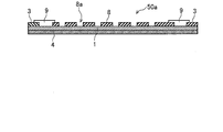
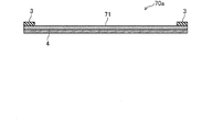
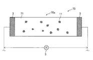
- FIG. 15 is a top view of the corrosion monitoring apparatus 70 of the comparative example.
- FIG. 16 is an end view taken along line IV-IV in FIG.
- a thin film copper plate 71 to be corroded is laminated on an insulating substrate 4 made of an insulating material.
- the insulating substrate 4 and the copper plate 71 are both long.
- a pair of lead electrodes 3 and 3 are formed on the upper surface of the copper plate 71 at both ends in the longitudinal direction.
- the insulating substrate 4, the copper plate 71, and the extraction electrodes 3 and 3 constitute a sensor unit 70 a that detects corrosion (rust) of the copper plate 71.
- the lead electrodes 3 and 3 are connected to an ohmmeter 5 and a power supply device (not shown). Then, the electrical resistance between the extraction electrodes 3 and 3 when a direct current or an alternating current (for example, about several mA) is passed between the extraction electrodes 3 and 3 from the power supply device is measured by the resistance meter 5.
- a protective film made of silicone resin, urethane resin, epoxy resin or the like is formed on the outer surfaces of the extraction electrodes 3 and 3 to prevent corrosion.
- Copper chloride or copper oxide obtained by corrosion (that is, chlorination or oxidation) of copper constituting the copper plate 71 has a large electric resistance (so-called insulator). Therefore, a change in electrical resistance between the extraction electrodes 3 and 3 caused by the generation of such copper chloride or copper oxide on the surface of the copper plate 71 is measured by the resistance meter 5.
- the amount of corrosion is measured based on the electrical resistance value that increases as the copper plate 71 that is the object of corrosion corrodes. That is, according to the study by the present inventor, it has been found that there is a correlation between the amount of change in the electrical resistance value, the amount of salt and dust deposited and the amount of corrosion of the copper plate 71. Therefore, based on the amount of change in the electrical resistance value, the amount of salt and dust attached and the amount of corrosion of the copper plate 71 can be evaluated. Specifically, for example, the corrosiveness of the environment can be diagnosed according to the ISO 11844-1 standard.
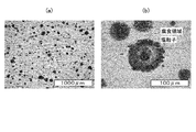
- FIG. 17 is a drawing-substituting photograph showing the state of corrosion of the metal plate due to salt, and the right-side view is an enlarged view 10 times the left-side view.
- the metal plate used in FIG. 17 is a copper plate, and FIG. 17 shows salt particles (corresponding to salt content 6 described later) formed on the surface of the copper plate and a corrosion area (corrosion shown in FIG. Corresponding to pit 11).
- the salt particles are substantially circular in top view, and the corrosion area is substantially annular so as to surround the salt particles in top view. As shown in the diagram on the right side of FIG.
- salt particles having a diameter of several tens of ⁇ m are adhered at intervals of about 50 ⁇ m to 100 ⁇ m, and the salt particles are liquefied, and a corroded region is formed under the water film around the salt particles. Is formed.
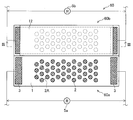
- FIG. 18 is a diagram showing a state of the corrosion pit 11 generated on the surface of the copper plate 71 constituting the corrosion monitoring apparatus 70 of the comparative example.
- the corrosion monitoring device 70 When the corrosion monitoring device 70 is exposed to an environment in which salt and dust fly, salt and dust adhere to the copper plate 71 constituting the corrosion monitoring device 70 (more specifically, the sensor unit 70a). At this time, salt and dust are considered to adhere at intervals of about 50 ⁇ m to 100 ⁇ m, as described with reference to FIG. Therefore, it is considered that the corrosion pits 11 which are corrosion areas generated on the surface of the copper plate 71 are also generated at intervals of about 50 ⁇ m to 100 ⁇ m.
- the corrosion monitoring device 70 monitors (evaluates) the degree of corrosion based on the change in electrical resistance value that increases as the copper plate 71 to be corroded uniformly corrodes. Therefore, as shown in FIG. 18, the local resistance such as the locally generated corrosion pit 11 is low in sensitivity of the electric resistance value, and it is difficult to accurately monitor the local corrosion due to salt or dust. In particular, details will be described later with reference to FIG. 6, but according to the study of the present inventor, even if the cross-sectional area is reduced by forming the corrosion pits 11 locally as shown in FIG. The change in resistance value is slight, and it is considered that the response sensitivity is not good. Therefore, the present inventor has examined a corrosion monitoring device that is excellent in durability and responsiveness.
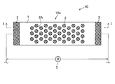
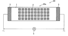
- FIG. 1 is a top view of the corrosion monitoring apparatus 10 of the first embodiment.
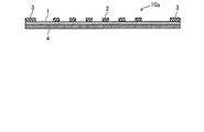
- FIG. 2 is an end view taken along the line II of FIG.
- the electrical resistance between the extraction electrodes 3 and 3 connected to the stainless steel plate 1 is measured by the ohmmeter 5 (resistance measurement device) as in the case of the corrosion monitoring device 70.
- a flat stainless steel (SUS, stainless steel, first metal) plate 1 is bonded (laminated) to the surface of the insulating substrate 4.
- a plurality of circular aluminum (second metal) pieces 2 are joined (laminated) in a scattered manner on the surface of the stainless steel plate 1 in a top view. That is, the sensor unit 10 a constituting the corrosion monitoring apparatus 10 includes a stainless plate 1, an aluminum piece 2, lead electrodes 3 and 3, and an insulating substrate 4.
- the thickness of the aluminum piece 2 can be easily made uniform when the aluminum piece 2 is joined to the stainless steel plate 1. Therefore, when the aluminum 2 corrodes, the aluminum piece 2 becomes easy to corrode uniformly, and the local corrosion of the aluminum piece 2 is prevented.
- the contact portion of the water film 7 (described later) with the aluminum piece 2 is a part of a circle (arc) that forms the outer periphery of the aluminum piece 2. Therefore, the degree of progress of corrosion is the same regardless of the corrosion position of dust and salt, and in this respect as well, local corrosion of the aluminum piece 2 is prevented.
- a plurality of the aluminum pieces 2 are joined so that the adjacent aluminum pieces 2 are positioned at the respective apexes of the regular hexagon 2A.
- interval of adjacent aluminum pieces 2 can be made equal. Therefore, it is possible to easily corrode each aluminum piece 2 in a similar manner regardless of the adhesion position of dust and salt.
- the thickness of the aluminum piece 2 is, for example, about 10 ⁇ m or less, preferably about 1 ⁇ m or less.
- the size of the circular aluminum piece 2 is, for example, about 50 ⁇ m to 100 ⁇ m in diameter. Further, the interval between adjacent aluminum pieces 2 is, for example, about 50 ⁇ m to 100 ⁇ m.
- the stainless steel plate 1 may use a plate material, and can be bonded to the surface of the insulating substrate 4 by sputtering, vapor deposition, plating, or the like. Moreover, the aluminum piece 2 can be joined to the surface of the stainless steel plate 1 by sputtering, vapor deposition, plating, or the like.
- FIG. 3 is a diagram showing how the corrosion of the aluminum piece 2 proceeds when the salt content 6 adheres to the corrosion monitoring device 10 (more specifically, the sensor unit 10a) of the first embodiment.
- the middle figure is the state when the water film 7 formed by deliquescence of the attached salt 6 bridges the stainless steel plate 1 and the aluminum piece 2, and the right figure is crosslinked.
- It is a figure which shows a mode when corrosion (dissolution) of the aluminum piece 2 advances with the water film 7.
- FIG. Here, for simplification of explanation, only “salt content 6” is illustrated, but “dust” has the same tendency. In the following description, explanation of “dust” is also omitted.
- the aluminum constituting the aluminum piece 2 is more easily corroded as described above than the stainless steel constituting the stainless steel plate 1. Therefore, as shown in the diagram on the right side of FIG. 3, the corrosion of the aluminum piece 2, which is a base metal that is easily corroded, proceeds by the water film 7 formed so as to straddle the stainless steel plate 1 and the aluminum piece 2. At this time, corrosion of the stainless steel plate 1 serving as a noble metal is suppressed.
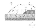
- FIG. 4 is a diagram for explaining a reaction mechanism that occurs between the stainless steel plate 1 and the aluminum piece 2.
- a part of the chemical formula is omitted for simplification of description.
- the anode reaction metal dissolution reaction: Al ⁇ Al 3+ + 3e ⁇
- the aluminum piece 2 is dissolved in the water film 7.
- the electrons generated here move to the stainless steel plate 1 joined to the aluminum piece 2.
- the cathode reaction reaction of dissolved oxygen: 1/2 ⁇ O 2 + H 2 O + 2e ⁇ ⁇ 2OH ⁇
- the cathode reaction reaction of dissolved oxygen: 1/2 ⁇ O 2 + H 2 O + 2e ⁇ ⁇ 2OH ⁇
- Corrosion caused by bringing different metals into contact with each other proceeds in such a manner that the anode (oxidation reaction) and the cathode (reduction reaction) are locally separated.
- the galvanic current is concentrated in the vicinity of the interface between the stainless steel plate 1 and the aluminum piece 2. Therefore, as shown in FIG. 4, corrosion progresses from the left side to the right side of the aluminum piece 2. And after all the aluminum pieces 2 corrode, the independent corrosion reaction of the stainless steel plate 1 proceeds.
- the stainless steel plate 1 is a metal that hardly corrodes, and even if it corrodes, the corrosion pits 11 (see FIG. 18 described above) are localized. Therefore, the change in the electrical resistance value due to the formation of the corrosion pits 11 can be ignored.
- FIG. 5 is a diagram showing a change in an equivalent circuit of electrical resistance before and after the aluminum piece 2 is melted.
- This FIG. 5 explains the measurement principle by the corrosion monitoring apparatus 10 of the first embodiment.
- the electrical resistivity of aluminum (second metal) is smaller than that of stainless steel (first metal). That is, stainless steel has a lower electrical conductivity than aluminum. Therefore, in the figure on the left side of FIG. 5, when a current flows between the extraction electrodes 3 and 3 (see FIG. 1), in the portion where the stainless steel 1 and the aluminum 2 are joined, the aluminum 2 is more than the stainless plate 1. A current flows preferentially (thick arrow in the left diagram of FIG. 5).
- resistances R C1 and R C3 are provided in the portion of the stainless steel plate 1 to which the aluminum piece 2 is not joined, as shown in the lower part of the left side of FIG. Think of it as connected.
- the joint portion of the stainless plate 1 and the aluminum piece 2 since the in stainless steel and aluminum, as there is a difference in electrical resistivity, the resistance R C2 in the portion of the stainless steel plate 1, also aluminum It can be considered that the resistor R A21 is connected in parallel in the portion 2. At this time, R C2 > R A21 is established.
- the entire resistance increases from R 0 to R 1 by melting the aluminum piece 2.
- Such a resistance change is continuously generated as the aluminum piece 2 is melted. Therefore, in the corrosion monitoring apparatus 10 of the first embodiment, the dissolution of the aluminum piece 2, that is, the degree of corrosion of the metal is monitored by monitoring the entire resistance change (rise). And since an electrical resistance changes immediately because the aluminum piece 2 melt
- the corrosion monitoring apparatus 10 since the environment in which the corrosion monitoring apparatus 10 is installed can be predicted to some extent, the ease of metal corrosion can also be predicted to some extent. Therefore, depending on the installation location of the corrosion monitoring device 10, the number of aluminum pieces 2 can be increased, the thickness of the aluminum pieces 2 can be increased, or the size of the aluminum pieces 2 can be increased. The aluminum piece 2 can be melted and the durability can be improved.
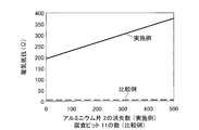
- FIG. 6 shows the number of disappearances of aluminum pieces 2 and the number of corrosion pits 11 in the corrosion monitoring apparatus of the example (corrosion monitoring apparatus 10 shown in FIG. 1) and the corrosion monitoring apparatus of the comparative example (corrosion monitoring apparatus 70 shown in FIG. 15). It is a graph which shows the relationship between the number of (refer FIG. 18), and an electrical resistance.
- the stainless steel plate 1 and the copper plate 71 used in the corrosion monitoring devices 10 and 70 those having a width of 1 mm ⁇ a length of 25 mm ⁇ a thickness of 100 nm were used.
- the size of the aluminum piece 2 used in the corrosion monitoring apparatus 10 is 50 ⁇ m in diameter ⁇ 100 nm in thickness, and 500 pieces are arranged at intervals of 50 ⁇ m.
- FIG. 6 is a graph showing resistance values measured by the ohmmeter 5 while a current of 5 mA is continuously supplied to each of the corrosion monitoring devices 10 and 70.
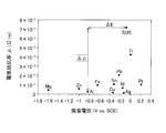
- FIG. 7 is a graph (plot) showing the relationship between the corrosion potential and the electrical resistivity in seawater.
- the corrosion potential shown on the horizontal axis of FIG. 7 is for a saturated calomel electrode (SCE) as a reference electrode.
- SCE saturated calomel electrode
- the corrosion potential in an aqueous solution in which salinity has been deliquescent / dissolved is not shown, but the relationship between the corrosion potential and the electrical resistivity for an aqueous solution in which salinity has been liquefied / dissolved.
- the tendency is the same as the tendency shown in FIG.
- stainless steel (stainless steel plate 1) is used as a metal that is not easily corroded
- aluminum (aluminum piece 2) is used as a metal that is easily corroded.
- the combination of metals that can be used is not limited to such a combination, and can be appropriately selected based on, for example, the graph of FIG.
- first metal a metal that can be used in place of the stainless steel
- second metal a metal that can be used in place of the above-mentioned aluminum
- the difference ⁇ in electrical resistivity between the first metal and the second metal is large.
- ⁇ is large, the resistance change when the second metal is dissolved (corroded) can be increased, and the responsiveness can be enhanced.
- the potential difference ⁇ E of the corrosion potential between the first metal and the second metal is large from the viewpoint of suppressing the corrosion of the first metal as much as possible and enhancing the responsiveness by promoting the corrosion of the second metal as much as possible. Is preferred.
- ⁇ E is too large, the corrosion of the second metal proceeds excessively, and the durability tends to be lowered. Therefore, in such a case, for example, the durability can be improved by increasing the thickness of the second metal or increasing the size of the second metal.
- the change in the electrical resistance in the corrosion monitoring apparatus 10 of the first embodiment, particularly the sensor unit 10a is the difference in the corrosion potential ⁇ E between the first metal and the second metal, the first metal and the second metal. Difference in electrical resistivity ⁇ , the shape of the second metal (including the size and thickness), the interval between adjacent second metal pieces, and the like.
- the first metal whose corrosion is suppressed preferably has a small resistance temperature coefficient.
- the resistance temperature coefficient is large, for example, using a separate thermometer and correcting the measured resistance according to the temperature measured by the thermometer, corrosion can be performed with high accuracy. Can be monitored.
- the second metal to be corroded is preferably at least one of iron, copper, zinc and magnesium in addition to the above-mentioned aluminum.
- the metal having a small temperature coefficient of resistance is preferable as the first metal in which corrosion is suppressed as much as possible
- at least one of nickel and chromium is preferable in addition to the stainless steel (SUS).
- SUS stainless steel
- chromium is not shown in FIG. 7, but chromium exhibits an electrical resistivity equivalent to that of lead and a corrosion potential comparable to that of stainless steel (SUS) or nickel.
- a single first metal is combined with the second metal which is substantially at the lower left when viewed from the plot of the first metal, as shown in FIG. (For example, a combination of stainless steel (SUS) and aluminum).
- FIG. 8 is a top view of the corrosion monitoring apparatus 20 of the second embodiment.
- the size of the aluminum piece 2 is rectangular (square).
- the other configuration is the same as that of the corrosion monitoring apparatus 10 described above, and the sensor unit 20a is configured by including the rectangular aluminum piece 2.
- One side of the aluminum piece 2 is, for example, about 50 ⁇ m to 100 ⁇ m.
- the intervals between adjacent aluminum pieces 2 are equal (for example, about 50 ⁇ m to 100 ⁇ m).
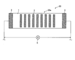
- FIG. 9 is a top view of the corrosion monitoring apparatus 30 of the third embodiment.
- a plurality of rectangular aluminum pieces 2 are joined in a direction perpendicular to the direction of current flow (the left-right direction in FIG. 9).
- the other configuration is the same as that of the corrosion monitoring apparatus 10 described above, and the sensor unit 30a is configured by including the rectangular aluminum piece 2.
- size of the aluminum piece 2 can be made larger than the thing of the said corrosion monitoring apparatus 10 and 20, and the corrosion of the aluminum piece 2 progresses over a long period of time. Therefore, the resistance change can be continuously monitored over a long period of time, and the durability of the corrosion monitoring device 30 can be improved.
- the number of joined aluminum pieces 2 can be increased while ensuring a large area of the aluminum pieces 2. Thereby, even if one aluminum piece 2 corrodes locally, the aluminum piece 2 continues to corrode due to the corrosion of the remaining aluminum pieces 2. Thereby, a resistance change can be monitored and the durability of the corrosion monitoring apparatus 30 can be improved also in this respect.
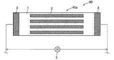
- FIG. 10 is a top view of the corrosion monitoring apparatus 40 of the fourth embodiment.
- a plurality of rectangular aluminum pieces 2 are joined in the same direction as the current flow direction (the left-right direction in FIG. 9).
- the other configuration is the same as that of the corrosion monitoring apparatus 10 described above, and the sensor unit 40a is configured by including the rectangular aluminum piece 2.
- size of the aluminum piece 2 can be made larger than the thing of the said corrosion monitoring apparatus 10 and 20, and the durability of the corrosion monitoring apparatus 40 can be improved. .
- the corrosion monitoring device 40 when corrosion occurs locally, the aluminum piece 2 that is long in the direction of current flow may be cut off. As a result, the electrical resistance, which has been reduced by the arrangement in the direction of current flow, greatly increases. In such a case, it is considered that the environment in which the corrosion monitoring device 40 is installed is an environment in which local corrosion is likely to occur. Since local corrosion of electrical and electronic devices leads to failure of electrical and electronic devices in particular, early detection of such high potential for local corrosion suppresses early failure of electrical and electronic devices. can do.
- FIG. 11 is a top view of the corrosion monitoring apparatus 50 of the fifth embodiment.
- FIG. 12 is an end view taken along line II-II in FIG.
- a plurality of aluminum pieces 2 are joined to the surface of the stainless steel plate 1.
- the stainless steel plate 1 and the aluminum plate 2 having a plurality of circular through holes 8 a are joined (laminated) on the insulating substrate 4. That is, the stainless steel plate 1 is laminated on the insulating substrate 4, and the aluminum plate 2 is laminated on the surface of the stainless steel plate 1.
- the size of the through hole 8a is the same as the size of the aluminum piece 2 described above. Further, the through hole 8a is arranged so as to be positioned at each vertex of the regular hexagon as in the regular hexagon 2A with reference to FIG.
- the corrosion monitoring apparatus 50 includes the stainless steel plate 1, the aluminum plate 8 having the through holes 8 a, the insulating substrate 4, the extraction electrodes 3 and 3, and the coating 9, thereby forming a sensor unit 50 a.
- the surface of the stainless steel plate 1 is exposed to the outside through the through hole 8a in a top view.
- the through hole 8 a is depressed, so that the water film 7 (see FIG. 11 and FIG. 11) is formed in the through hole 8 a. (Not shown in FIG. 12) tends to accumulate. Therefore, the water film 7 can easily come into contact with both the stainless steel constituting the stainless steel plate 1 and the aluminum constituting the aluminum plate 2, and the reaction as described with reference to FIG. 4 can be promoted.
- the volume of the aluminum plate 2 that is a metal to be corroded is extremely large as compared with the above-described embodiments. Therefore, the corrosion of the metal can be monitored especially over a long period of time. Furthermore, since the joining area of the stainless steel plate 1 and the aluminum plate 2 is large, the adhesion strength of the aluminum plate 2 is high. Therefore, peeling of the aluminum plate 2 can be sufficiently prevented and durability can be enhanced.
- FIG. 13 is a top view of the corrosion monitoring apparatus 60 of the sixth embodiment.
- FIG. 14 is an end view taken along line III-III in FIG.
- the corrosion monitoring apparatus 60 shown in FIGS. 13 and 14 includes a sensor unit 60a having the stainless steel plate 1 and the aluminum piece 2 to be subjected to corrosion, and a reference sensor unit 60b that also has the stainless steel plate 1 and the aluminum piece 2 but does not corrode. I have.
- the sensor unit 60a has the same configuration as the sensor unit 10a shown in FIG. 1, and the electric resistance at the time of current flow is measured by the resistance meter 5a.
- the reference sensor unit 60b includes a coating 12 formed so as to cover the stainless steel plate 1 and the aluminum piece 2 constituting the sensor unit 10a (see FIG. 1). And the electrical resistance at the time of current flow is measured by the ohmmeter 5b.
- the coating 12 is formed for moisture proofing and gas proofing, and is made of silicone resin, urethane resin, epoxy resin, or the like.
- the metal resistance may change depending on the temperature. Therefore, in the corrosion monitoring device 60 shown in FIGS. 13 and 14, the metal corrosion is monitored in consideration of such a temperature change. Specifically, by evaluating the difference between the resistance value in the corrosion monitoring device 60a and the resistance value in the corrosion monitoring device 60b, the corrosion of the metal in consideration of the temperature can be monitored. Thereby, the metal corrosion can be monitored with higher accuracy.
- the present invention has been described with reference to six embodiments, the present invention is not limited to the above examples.
- the embodiments described above can be implemented in combination as appropriate.
- it can also implement after adding various deformation
- the stainless steel plate 1 that is a metal that is not easily corroded and the aluminum pieces 2 and the aluminum plate 8 that are easily corroded are joined to the surface of the insulating substrate 4 in this order.
- the joining order (stacking order) of the stainless steel plate 1 and the aluminum piece 2 or the aluminum plate 8 may be reversed. That is, for example, the insulating substrate 4, the aluminum plate 8, and the stainless steel plate 1 having a through hole may be joined in this order.
- the extraction electrodes 3 and 3 are connected to the stainless steel plate 1.
Landscapes
- Chemical & Material Sciences (AREA)
- Life Sciences & Earth Sciences (AREA)
- Health & Medical Sciences (AREA)
- General Health & Medical Sciences (AREA)
- Immunology (AREA)
- Physics & Mathematics (AREA)
- Pathology (AREA)
- General Physics & Mathematics (AREA)
- Analytical Chemistry (AREA)
- Biochemistry (AREA)
- Chemical Kinetics & Catalysis (AREA)
- Electrochemistry (AREA)
- Biodiversity & Conservation Biology (AREA)
- Ecology (AREA)
- Environmental Sciences (AREA)
- Environmental & Geological Engineering (AREA)
- Crystallography & Structural Chemistry (AREA)
- Engineering & Computer Science (AREA)
- Food Science & Technology (AREA)
- Medicinal Chemistry (AREA)
- Testing Resistance To Weather, Investigating Materials By Mechanical Methods (AREA)
- Investigating Or Analyzing Materials By The Use Of Electric Means (AREA)
Priority Applications (3)
| Application Number | Priority Date | Filing Date | Title |
|---|---|---|---|
| KR1020197009981A KR102274158B1 (ko) | 2016-11-18 | 2017-10-23 | 부식 감시 장치 |
| US16/461,662 US11029273B2 (en) | 2016-11-18 | 2017-10-23 | Corrosion monitoring device |
| CN201780071207.XA CN109964120A (zh) | 2016-11-18 | 2017-10-23 | 腐蚀监视装置 |
Applications Claiming Priority (2)
| Application Number | Priority Date | Filing Date | Title |
|---|---|---|---|
| JP2016225394A JP6815841B2 (ja) | 2016-11-18 | 2016-11-18 | 腐食監視装置 |
| JP2016-225394 | 2016-11-18 |
Publications (1)
| Publication Number | Publication Date |
|---|---|
| WO2018092519A1 true WO2018092519A1 (ja) | 2018-05-24 |
Family
ID=62145412
Family Applications (1)
| Application Number | Title | Priority Date | Filing Date |
|---|---|---|---|
| PCT/JP2017/038201 Ceased WO2018092519A1 (ja) | 2016-11-18 | 2017-10-23 | 腐食監視装置 |
Country Status (5)
| Country | Link |
|---|---|
| US (1) | US11029273B2 (enExample) |
| JP (1) | JP6815841B2 (enExample) |
| KR (1) | KR102274158B1 (enExample) |
| CN (1) | CN109964120A (enExample) |
| WO (1) | WO2018092519A1 (enExample) |
Cited By (1)
| Publication number | Priority date | Publication date | Assignee | Title |
|---|---|---|---|---|
| US20210341381A1 (en) * | 2018-09-27 | 2021-11-04 | Nippon Telegraph And Telephone Corporation | Corrosivity Evaluation Device and Method Thereof |
Families Citing this family (4)
| Publication number | Priority date | Publication date | Assignee | Title |
|---|---|---|---|---|
| JP6958863B2 (ja) * | 2018-06-27 | 2021-11-02 | 矢崎総業株式会社 | 電気的接続部の劣化度合診断装置、及び、劣化度合診断方法 |
| US11549797B2 (en) * | 2018-10-26 | 2023-01-10 | Deere & Company | Device for detecting wear of replaceable components |
| JP7437656B2 (ja) * | 2020-08-24 | 2024-02-26 | パナソニックIpマネジメント株式会社 | 冷凍サイクル装置及び冷凍サイクルシステム |
| JP7426660B2 (ja) * | 2020-08-24 | 2024-02-02 | パナソニックIpマネジメント株式会社 | 冷凍サイクルシステム及び分析方法 |
Citations (3)
| Publication number | Priority date | Publication date | Assignee | Title |
|---|---|---|---|---|
| JP2009150806A (ja) * | 2007-12-21 | 2009-07-09 | Nec Corp | 腐食センサ、液体の検出方法、腐食センサの製造方法及び腐食検出装置 |
| US20110187395A1 (en) * | 2008-05-20 | 2011-08-04 | Bae Systems Plc | Corrosion sensors |
| WO2013042179A1 (ja) * | 2011-09-20 | 2013-03-28 | 株式会社日立製作所 | 腐食環境モニタ装置およびその方法 |
Family Cites Families (16)
| Publication number | Priority date | Publication date | Assignee | Title |
|---|---|---|---|---|
| DE3834628A1 (de) * | 1988-10-11 | 1990-04-12 | Peter Dr Ing Schiessl | Korrosionsmesszelle |
| CN2430686Y (zh) * | 2000-04-25 | 2001-05-16 | 王佳 | 孔蚀深度监测探头 |
| JP4745811B2 (ja) * | 2005-12-14 | 2011-08-10 | 太平洋セメント株式会社 | 腐食検知部材および腐食センサ |
| CN101398369A (zh) * | 2007-09-30 | 2009-04-01 | 通用电气公司 | 监测表面腐蚀的设备和方法 |
| CN101334353B (zh) * | 2008-08-01 | 2010-12-08 | 厦门大学 | 一种用于监测钢筋混凝土结构腐蚀的多功能传感器 |
| EP2354780A1 (en) * | 2008-12-02 | 2011-08-10 | Mitsubishi Heavy Industries, Ltd. | Outdoor structure and method of estimating deterioration of component member of outdoor structure |
| US8466695B2 (en) * | 2010-08-19 | 2013-06-18 | Southwest Research Institute | Corrosion monitoring of concrete reinforcement bars (or other buried corrodable structures) using distributed node electrodes |
| US8723534B2 (en) * | 2011-01-10 | 2014-05-13 | International Business Machines Corporation | Methods and apparatus for detection of gaseous corrosive contaminants |
| JP2012208088A (ja) | 2011-03-30 | 2012-10-25 | Tokyo Electric Power Co Inc:The | 腐食モニタリングセンサ |
| US20140159751A1 (en) * | 2012-08-20 | 2014-06-12 | Lloyd Hihara | Passive Multi-Layered Corrosion Sensor |
| CN103149146A (zh) * | 2013-02-01 | 2013-06-12 | 厦门大学 | 一种用于监测工业设备腐蚀的多功能腐蚀监测探头 |
| CN103226129A (zh) * | 2013-02-27 | 2013-07-31 | 常州兆能电子科技有限公司 | 一种基于平面电磁传感器的板材损伤探测装置及方法 |
| JP6084935B2 (ja) | 2013-09-06 | 2017-02-22 | 国立大学法人九州大学 | 腐食センサおよびその製造方法 |
| JP5488755B1 (ja) | 2013-09-26 | 2014-05-14 | 日新電機株式会社 | 汚損監視装置 |
| US9704761B2 (en) * | 2014-09-17 | 2017-07-11 | Lam Research Corporation | Corrosion sensor retainer assembly apparatus and method for detecting corrosion |
| JP6574356B2 (ja) | 2015-08-05 | 2019-09-11 | 太平洋セメント株式会社 | 静電容量型腐食センサおよび腐食検出方法 |
-
2016
- 2016-11-18 JP JP2016225394A patent/JP6815841B2/ja active Active
-
2017
- 2017-10-23 US US16/461,662 patent/US11029273B2/en active Active
- 2017-10-23 WO PCT/JP2017/038201 patent/WO2018092519A1/ja not_active Ceased
- 2017-10-23 KR KR1020197009981A patent/KR102274158B1/ko active Active
- 2017-10-23 CN CN201780071207.XA patent/CN109964120A/zh active Pending
Patent Citations (3)
| Publication number | Priority date | Publication date | Assignee | Title |
|---|---|---|---|---|
| JP2009150806A (ja) * | 2007-12-21 | 2009-07-09 | Nec Corp | 腐食センサ、液体の検出方法、腐食センサの製造方法及び腐食検出装置 |
| US20110187395A1 (en) * | 2008-05-20 | 2011-08-04 | Bae Systems Plc | Corrosion sensors |
| WO2013042179A1 (ja) * | 2011-09-20 | 2013-03-28 | 株式会社日立製作所 | 腐食環境モニタ装置およびその方法 |
Cited By (1)
| Publication number | Priority date | Publication date | Assignee | Title |
|---|---|---|---|---|
| US20210341381A1 (en) * | 2018-09-27 | 2021-11-04 | Nippon Telegraph And Telephone Corporation | Corrosivity Evaluation Device and Method Thereof |
Also Published As
| Publication number | Publication date |
|---|---|
| KR20190051016A (ko) | 2019-05-14 |
| JP2018081061A (ja) | 2018-05-24 |
| US20190353608A1 (en) | 2019-11-21 |
| CN109964120A (zh) | 2019-07-02 |
| KR102274158B1 (ko) | 2021-07-08 |
| JP6815841B2 (ja) | 2021-01-20 |
| US11029273B2 (en) | 2021-06-08 |
Similar Documents
| Publication | Publication Date | Title |
|---|---|---|
| WO2018092519A1 (ja) | 腐食監視装置 | |
| JP4745811B2 (ja) | 腐食検知部材および腐食センサ | |
| US7313947B2 (en) | Corrosion sensing microsensors | |
| US6077418A (en) | Corrosion monitoring | |
| JP6506849B2 (ja) | 腐食環境モニタリング装置及び方法 | |
| US9291543B1 (en) | PC board mount corrosion sensitive sensor | |
| AU2009248504B2 (en) | Corrosion sensors | |
| JP5626380B2 (ja) | 孔食モニタリング用テストピースおよび孔食モニタリング装置並びに孔食モニタリング方法 | |
| JP6362920B2 (ja) | 腐食環境モニタリング装置及び方法 | |
| US7388386B2 (en) | Method and apparatus for corrosion detection | |
| JP2012208088A (ja) | 腐食モニタリングセンサ | |
| US20060002815A1 (en) | Corrosion sensing microsensors | |
| JP7401387B2 (ja) | 腐食環境モニタリング装置 | |
| JP2018081061A5 (enExample) | ||
| JP7443580B2 (ja) | 腐食センサ | |
| JP2009150806A (ja) | 腐食センサ、液体の検出方法、腐食センサの製造方法及び腐食検出装置 | |
| JP2008209180A (ja) | 測定電極、腐食監視装置及び腐食監視方法 | |
| JP7063737B2 (ja) | 鋼構造物の防食状態監視システム | |
| EP2124035A1 (en) | Corrosion sensors | |
| EP2238429A1 (en) | Degradation sensor | |
| JP6381167B1 (ja) | Acmセンサを用いた腐食速度測定方法及び環境モニタリング装置 | |
| JP2019203776A (ja) | 腐食検出装置、腐食状態判定システム及び腐食検出方法 | |
| CN117607023A (zh) | 一种用于材料腐蚀监测的电阻探针 | |
| JP2013072647A (ja) | 保護膜の性能評価方法および保護膜の性能評価装置 | |
| Mat et al. | Development of Eletrical Resistance Based Corrosion Rate Sensor |
Legal Events
| Date | Code | Title | Description |
|---|---|---|---|
| 121 | Ep: the epo has been informed by wipo that ep was designated in this application |
Ref document number: 17872607 Country of ref document: EP Kind code of ref document: A1 |
|
| ENP | Entry into the national phase |
Ref document number: 20197009981 Country of ref document: KR Kind code of ref document: A |
|
| NENP | Non-entry into the national phase |
Ref country code: DE |
|
| 122 | Ep: pct application non-entry in european phase |
Ref document number: 17872607 Country of ref document: EP Kind code of ref document: A1 |