WO2018092405A1 - 地図データ提供システム - Google Patents
地図データ提供システム Download PDFInfo
- Publication number
- WO2018092405A1 WO2018092405A1 PCT/JP2017/033622 JP2017033622W WO2018092405A1 WO 2018092405 A1 WO2018092405 A1 WO 2018092405A1 JP 2017033622 W JP2017033622 W JP 2017033622W WO 2018092405 A1 WO2018092405 A1 WO 2018092405A1
- Authority
- WO
- WIPO (PCT)
- Prior art keywords
- map
- vehicle
- data
- unit
- map data
- Prior art date
Links
Images


Classifications
-
- G—PHYSICS
- G01—MEASURING; TESTING
- G01C—MEASURING DISTANCES, LEVELS OR BEARINGS; SURVEYING; NAVIGATION; GYROSCOPIC INSTRUMENTS; PHOTOGRAMMETRY OR VIDEOGRAMMETRY
- G01C21/00—Navigation; Navigational instruments not provided for in groups G01C1/00 - G01C19/00
- G01C21/38—Electronic maps specially adapted for navigation; Updating thereof
- G01C21/3804—Creation or updating of map data
- G01C21/3807—Creation or updating of map data characterised by the type of data
- G01C21/3811—Point data, e.g. Point of Interest [POI]
-
- G—PHYSICS
- G01—MEASURING; TESTING
- G01C—MEASURING DISTANCES, LEVELS OR BEARINGS; SURVEYING; NAVIGATION; GYROSCOPIC INSTRUMENTS; PHOTOGRAMMETRY OR VIDEOGRAMMETRY
- G01C21/00—Navigation; Navigational instruments not provided for in groups G01C1/00 - G01C19/00
- G01C21/38—Electronic maps specially adapted for navigation; Updating thereof
- G01C21/3863—Structures of map data
- G01C21/387—Organisation of map data, e.g. version management or database structures
- G01C21/3881—Tile-based structures
-
- G—PHYSICS
- G01—MEASURING; TESTING
- G01C—MEASURING DISTANCES, LEVELS OR BEARINGS; SURVEYING; NAVIGATION; GYROSCOPIC INSTRUMENTS; PHOTOGRAMMETRY OR VIDEOGRAMMETRY
- G01C21/00—Navigation; Navigational instruments not provided for in groups G01C1/00 - G01C19/00
- G01C21/38—Electronic maps specially adapted for navigation; Updating thereof
- G01C21/3885—Transmission of map data to client devices; Reception of map data by client devices
- G01C21/3889—Transmission of selected map data, e.g. depending on route
-
- G—PHYSICS
- G01—MEASURING; TESTING
- G01C—MEASURING DISTANCES, LEVELS OR BEARINGS; SURVEYING; NAVIGATION; GYROSCOPIC INSTRUMENTS; PHOTOGRAMMETRY OR VIDEOGRAMMETRY
- G01C21/00—Navigation; Navigational instruments not provided for in groups G01C1/00 - G01C19/00
- G01C21/38—Electronic maps specially adapted for navigation; Updating thereof
- G01C21/3885—Transmission of map data to client devices; Reception of map data by client devices
- G01C21/3896—Transmission of map data from central databases
-
- G—PHYSICS
- G09—EDUCATION; CRYPTOGRAPHY; DISPLAY; ADVERTISING; SEALS
- G09B—EDUCATIONAL OR DEMONSTRATION APPLIANCES; APPLIANCES FOR TEACHING, OR COMMUNICATING WITH, THE BLIND, DEAF OR MUTE; MODELS; PLANETARIA; GLOBES; MAPS; DIAGRAMS
- G09B29/00—Maps; Plans; Charts; Diagrams, e.g. route diagram
-
- G—PHYSICS
- G09—EDUCATION; CRYPTOGRAPHY; DISPLAY; ADVERTISING; SEALS
- G09B—EDUCATIONAL OR DEMONSTRATION APPLIANCES; APPLIANCES FOR TEACHING, OR COMMUNICATING WITH, THE BLIND, DEAF OR MUTE; MODELS; PLANETARIA; GLOBES; MAPS; DIAGRAMS
- G09B29/00—Maps; Plans; Charts; Diagrams, e.g. route diagram
- G09B29/10—Map spot or coordinate position indicators; Map reading aids
Definitions
- the present disclosure relates to a map data providing system that provides map data to a predetermined device.
- a map data providing system that can update map data provided in a navigation device to map data reflecting changes such as road connection relations as needed by communication between the center and the navigation device.
- a map data manager for example, a map creation company
- the center then distributes the difference map data representing the difference between the old version of the map data and the new version of the map data to the vehicle navigation device.
- the navigation device can use the map data in which the latest road network and facility information are described by combining the difference map data with the map data held by itself.
- High-precision map data includes not only road network connection relationships, road shapes, and intersection location information, but also map lines, temporary stop lines, traffic lights, road signs, etc. as map elements. This is map data shown with centimeter accuracy.
- the electronic control device that provides the automatic driving function recognizes the environment around the vehicle based on the high-precision map data and the position coordinates of the vehicle detected using GNSS (Global Navigation Satellite System), and the recognition result The travel is controlled based on the above.
- GNSS Global Navigation Satellite System
- the position coordinates of each point on the ground surface change over time due to crustal movements. For example, in Japan, it moves about an average of several centimeters per year. In North America and Europe, it moves about 3 to 5 cm per year. For this reason, if the position coordinates of the map elements registered in the map data are not updated, the error between the position coordinates of each point shown in the map data and the actual position coordinates will be the elapsed time from the time when the map data was created. It will increase accordingly.
- map data Since conventional map data is assumed to be used for route guidance processing, a certain amount of deviation (for example, about 10 meters) is allowed between the position coordinates of each point indicated in the map data and the actual position coordinates. It had been. However, the allowable range of error required for map data provided for automatic driving or the like is less than 25 cm. In recent years, the positioning accuracy by GNSS has been improved. However, even if the positioning accuracy is improved, it is difficult to utilize a highly accurate positioning result if the map data includes an error.
- the present disclosure has been made based on this situation, and the object of the present disclosure is to provide map data in which an error between the actual position coordinates and the position coordinates indicated in the map data is suppressed at a low cost. Is to provide a simple map data providing system.
- a map data providing system is a vehicle unit mounted on a vehicle and used for each section obtained by dividing position information of map elements existing in a map recording area into map recording areas.
- the map data includes a plurality of pieces of section data divided into two, each of which has a reference point set, and the position information of the plurality of reference points is expressed in absolute coordinates,
- the position information of the element receives the map data storage unit that stores the map data expressed by the relative coordinates indicating the relative position to the reference point set in the section to which the map element belongs, and the navigation signal transmitted by the positioning satellite
- a vehicle position detector that detects the position coordinates of the vehicle and a vehicle that is mounted on the vehicle and that is based on the position coordinates detected by the vehicle position detector.
- the traveling section data which is the section data for the section, and the position information of the reference point set in the traveling section, which is the section where the vehicle exists, and the relative coordinates for each map element shown in the traveling section data
- a vehicle unit including a deviation amount specifying unit that specifies a deviation amount indicating a difference between a position of the map element indicated in the data and a position where the map element actually exists, and the deviation amount specifying unit specifies Based on the deviation amount, a correction amount calculation unit that calculates a correction amount for aligning the coordinates of the reference point indicated in the travel section data with the actual position, and a correction amount determined by the correction amount calculation unit
- a corrected map generation unit that corrects the position information of the quasi-point and generates corrected map data indicating the position coordinates of each map element using the corrected position information of the reference point and the relative coordinates of each map
- map data in which an error between the actual position coordinates and the position coordinates indicated in the map data is suppressed can be provided at a low cost.
- FIG. 1 is a diagram illustrating a schematic configuration of a map data providing system according to an embodiment of the present disclosure.
- FIG. 2 is a diagram for explaining the structure of the basic map data.
- FIG. 3 is a diagram showing an example of the structure of the basic map data.
- FIG. 4 is a diagram showing an example of the configuration of link data.
- FIG. 5 is a diagram for explaining position information of map elements.
- FIG. 6 is a diagram illustrating an example of a schematic configuration of a vehicle unit.
- FIG. 7 is a diagram illustrating an example of a schematic configuration of the vehicle-side control unit.
- FIG. 1 is a diagram illustrating a schematic configuration of a map data providing system according to an embodiment of the present disclosure.
- FIG. 2 is a diagram for explaining the structure of the basic map data.
- FIG. 3 is a diagram showing an example of the structure of the basic map data.
- FIG. 4 is a diagram showing an example of the configuration of link data.
- FIG. 5 is a diagram
- FIG. 8 is a diagram showing an example of a schematic configuration of the center.
- FIG. 9 is a diagram for explaining a correction amount calculation method.
- FIG. 10 is a diagram for explaining the effect of the embodiment.
- FIG. 11 is a diagram showing a configuration of the map data providing system in the second modification.
- FIG. 12 is a diagram showing the configuration of the center in Modification 2.
- FIG. 13 is a diagram showing the configuration of the map data providing system in Modification 3.
- FIG. 14 is a diagram illustrating a configuration of a vehicle-side control unit in the third modification.
- FIG. 1 is a diagram illustrating an example of a schematic configuration of a map data providing system 100 according to the present disclosure.
- the map data providing system 100 includes a vehicle unit 1 and a center 2 mounted on a vehicle.
- the vehicle unit 1 for convenience, only one vehicle on which the vehicle unit 1 is mounted is illustrated, but two or more vehicles may exist.
- the map data providing system 100 Since the position coordinates of the map elements (in other words, the position on the earth) change over time due to crustal movement, they are shown in the basic map data according to the elapsed time since the basic map data was created. The error increases between the position coordinates and the actual position coordinates.
- the map data providing system 100 according to the present embodiment generates corrected map data in which an error between the position coordinates indicated in the basic map data and the actual position coordinates is suppressed, and sends the corrected map data to a predetermined map data request source. This system provides corrected map data.
- the basic map data here is map data indicating position information of various map elements specified by the surveying work.
- the vehicle unit 1 detects the degree of deviation between the position coordinates of each point indicated in the basic map data and the actual position coordinates (hereinafter, the amount of deviation) and reports it to the center 2.
- the center 2 generates correction data for correcting the deviation between the position coordinates of each point indicated in the basic map data and the actual position coordinates based on the deviation amount provided from the vehicle unit 1. To unit 1 for use.
- the vehicle unit 1 dynamically generates corrected map data by applying the correction data distributed from the center 2 to the basic map data included in the vehicle unit 1 and provides it to predetermined application software.
- application software that provides an automatic driving function (hereinafter referred to as an automatic driving application) or application software that provides a route guidance function (hereinafter referred to as a navigation application).
- the automatic driving application is installed in an ECU (Electronic Control Unit) provided separately from the vehicle unit 1, but is not limited thereto.
- the vehicle unit 1 itself may include an automatic driving application.
- a vehicle equipped with the vehicle unit 1 is a vehicle traveling on a road.
- the vehicle on which the vehicle unit 1 is mounted is a four-wheeled vehicle, but is not limited thereto.
- the vehicle unit 1 may be mounted on a two-wheeled vehicle, a three-wheeled vehicle, or the like.
- a two-wheeled vehicle may include a motorbike.
- the vehicle unit 1 is configured to be wirelessly connectable to the wide area communication network 3.
- the wide area communication network 3 here refers to a public communication network provided by a telecommunications carrier, such as a mobile phone network or the Internet.
- a base station 31 shown in FIG. 1 is a radio base station for connecting the vehicular unit 1 to the wide area communication network 3.
- the vehicle unit 1 has a function of detecting its current position by receiving radio waves transmitted from the GNSS satellite 4.
- the GNSS satellite 4 is a satellite used in a global navigation satellite system (GNSS).
- the GNSS satellite 4 transmits radio waves including data (so-called ephemeris) indicating the current position of the satellite itself.
- the radio wave transmitted by the GNSS satellite 4 is used by the vehicle unit 1 to identify the current position.
- GNSS satellite 4 corresponds to a positioning satellite.
- the vehicle unit 1 detects a deviation amount between the position coordinates indicated in the basic map data and the actual position coordinates by a method described later, and data indicating the detected deviation amount (hereinafter, deviation amount data)
- the data is sequentially transmitted to the center 2 via the base station 31 and the wide area communication network 3.
- the center 2 When the center 2 receives the deviation amount data transmitted from the vehicle unit 1, the center 2 stores the deviation amount indicated in the received deviation amount data in a predetermined database in association with the vehicle ID or the like. Then, by using a plurality of deviation amounts provided from the plurality of vehicle units 1 as a population, the deviation amount between the position coordinates of each point indicated by the basic map data and the actual position coordinates is analyzed. Further, based on the analysis result, correction data is generated and distributed to the vehicle unit 1.
- a terminal ID that is a unique identification number is assigned to each communication terminal (for example, the vehicle unit 1 or the center 2) that performs wide area communication.
- the basic map data is road data indicating road connection relations (so-called road network) in map recording areas (for example, all over Japan) and data representing facility information.
- the road data includes data indicating the installation positions of road signs, road markings, traffic lights, crossings, etc., in addition to data indicating road connection relations, road shapes, and the like. That is, an object (hereinafter referred to as a road installation) installed on a road such as a road sign is included as a recording target (hereinafter referred to as a map element).
- the basic map data is data indicating position information where these various map elements are provided.
- the road here includes, for example, a side area of the road on which the vehicle travels (that is, an area along the road) such as a sidewalk.
- the road installation includes objects formed on the road surface, such as lane markings.
- the road sign is a sign board that displays regulations or instructions regarding road traffic. Examples of road signs include guide signs, warning signs, regulatory signs, instruction signs, auxiliary signs, and the like.
- the road marking is a marking that displays regulations or instructions regarding road traffic, and refers to lines, symbols, or characters made of road fences, paint, stones, etc. drawn on the road surface. For example, lane markings indicating lane boundaries, temporary stop lines, and the like correspond to road markings.
- the basic map data includes map data for each section obtained by dividing the map recording area into a plurality of sections.
- map data for every division with which basic map data is provided are also described as division data.
- a group of these segment data is configured as a data group in which corresponding segment data is arranged in an order according to the geographical arrangement of the segments.
- the k-th partition data in the arrangement order is expressed as the k-th partition data.
- the first section data refers to the section data having the first arrangement order.
- k is a natural number.
- the number of compartments may be designed as appropriate, and here is 58000 as an example.
- Each segment data is configured as map data indicating the position of the map element in the corresponding segment.
- a reference point is set for each section.
- the section data includes reference coordinate data indicating the position coordinates of the reference point set in the section.
- the position coordinates here are coordinates (that is, absolute coordinates) in a predetermined three-dimensional coordinate system (for example, WGS-84 coordinate system).
- WGS is an abbreviation for World Geodetic System
- ITRF is an abbreviation for International Terrestrial Reference Frame.
- the three axial directions constituting the three-dimensional coordinate system are referred to as an X-axis direction, a Y-axis direction, and a Z-axis direction.
- the section data includes data about the road network provided in the section (that is, road data), facility data, and the like.
- the road data may be configured using, for example, node data for each node and link data for each link.
- a node is a binding point or a terminal point between roads such as an intersection.
- a link refers to a road connecting nodes.
- the node data describes a unique number (hereinafter referred to as a node ID) set for each node, a node type, information about a link connected to the node, and the like.
- the link data includes metadata, shape data, road sign data, traffic signal data, and road marking data.
- the metadata includes a unique number (hereinafter referred to as a link ID) set for each link, a link length indicating the length of the link, a node ID corresponding to the start end of the link, and a node ID corresponding to the end of the link. This is data indicating the road type and the like.
- the shape data is data indicating the shape of the link, and is data of a coordinate group representing the positions of a plurality of points set on the link.
- the road sign data is data indicating the installation position of the road sign.
- the traffic signal data is data indicating the presence or absence of a traffic signal and the installation position.
- the road marking data is data indicating the installation position of the road marking.
- the positions of various map elements such as a plurality of points set on the link to indicate the link shape, traffic lights, road signs, road markings, and the like indicate relative positions with respect to the reference point as shown in FIG. Expressed in relative coordinates.
- P1 shown in FIG. 5 represents a reference point set in the first section
- Q1 represents a certain map element existing in the first section.
- the position information of the reference point P1 of the first section is expressed by absolute coordinates, while the position of the map element Q1 is expressed by relative coordinates with respect to the reference point P1.
- the absolute coordinates of the map element Q1 are the coordinates obtained by combining them. That is, (px + qx1, py + qy1, pz + qz1).
- the reference coordinate data is stored in the partition data, but the present invention is not limited to this.
- the reference coordinate data may be stored in a separate table from the partition data. In that case, each section data shall be provided with the reference destination information for referring the reference
- the location information of various map elements included in the basic map data was surveyed and specified by government agencies and map makers (hereinafter referred to as map managers). Is. It is assumed that the basic map data includes data indicating the time when the basic map data is created (in other words, the time when surveying is performed) in addition to the map data for each section. For example, data such as the original period is included.
- FIG. 5 illustrates an example in which the reference point is arranged at a position corresponding to the lower left of the section
- the reference point may be set at the center of the section.
- a point where a typical structure exists in the section may be set as a reference point.
- the position as the reference point may be appropriately designed.
- the outline shape of a division is not restricted to a rectangle. It may be a polygonal shape other than a rectangle, such as a triangular shape or a hexagonal shape.
- the vehicle unit 1 is configured to be capable of mutual communication with an automatic driving ECU 6, a peripheral monitoring system 7, and the like via a communication network (that is, LAN: Local Area Network) 5 built in the vehicle. ing.
- a communication network that is, LAN: Local Area Network
- the vehicle on which the vehicle unit 1 is mounted is also referred to as the own vehicle.
- the automatic driving ECU 6 is an ECU including a computer in which an automatic driving application is installed.
- the automatic driving ECU 6 uses the map data (specifically, corrected map data) provided from the vehicle unit 1 and follows the travel plan (in other words, the planned travel route) set by the user. Steering, acceleration, deceleration, etc. are automatically executed so that the vehicle travels.
- the automatic driving ECU 6 and the vehicle unit 1 may be integrated as described above. That is, the vehicle unit 1 may be configured to provide an automatic driving function.
- the periphery monitoring system 7 is a system that detects the presence of a predetermined detection object around the host vehicle and identifies the relative position of the detected object (hereinafter, detected object) with respect to the host vehicle.
- detection objects include road signs, road markings, traffic lights, guardrails, utility poles, curbs, and ring stops.
- a part or all of road installations registered as map elements in basic map data, such as road signs and road markings, may be registered as detection objects.
- the specific contents of the detection target may be designed as appropriate.
- the periphery monitoring system 7 is realized by using a periphery monitoring sensor (SENS) 71 and an environment recognition ECU (ENV_ECU) 72.
- the periphery monitoring sensor 71 is a sensor for detecting a detection target.
- a surrounding monitoring camera that captures a predetermined range outside the vehicle for example, a millimeter wave radar that transmits an exploration wave to a predetermined range outside the vehicle, LIDAR (Light Detection R Ranging / Laser Imaging Detection and Ranging), etc. Can be adopted.
- the periphery monitoring sensor 71 is a periphery monitoring camera.
- the periphery monitoring camera as the periphery monitoring sensor 71 sequentially outputs captured images to be sequentially captured to the environment recognition ECU 72.
- the environment recognition ECU 72 performs a known image recognition process on the image data provided from the periphery monitoring camera as the periphery monitoring sensor 71 to detect a detection target such as a road sign. Moreover, the relative position with respect to the own vehicle of the detected object is specified.
- the detection result of the periphery monitoring system 7 is sequentially provided to the vehicle unit 1 via the LAN 5 (for example, every 100 milliseconds).
- the vehicle unit 1 includes a communication driver 11, a GNSS receiver 12, a wide area communication unit 13, a map data storage unit 14, and a vehicle side control unit 15.
- the communication driver 11 is a configuration for the vehicle-side control unit 15 to communicate with other configurations connected to the LAN 5 such as the automatic driving ECU 6 and the periphery monitoring system 7.
- the communication driver 11 is configured to be able to communicate with the vehicle-side control unit 15.
- the GNSS receiver 12 receives radio waves transmitted from the GNSS satellite 4. When four or more GNSS satellites are captured, the GNSS receiver 12 sequentially calculates (in other words, detects) the current position of the GNSS receiver 12 based on the radio wave received from each GNSS satellite. A radio wave transmitted from the GNSS satellite 4 corresponds to a navigation signal.
- the current position detected by the GNSS receiver 12 is represented by coordinates in a predetermined three-dimensional coordinate system.
- the current position is expressed in the WGS-84 coordinate system.
- the current position may be expressed in a coordinate system other than the WGS-84 coordinate system such as the ITRF coordinate system.
- the reference coordinate data included in the basic map data and the reference point relative position of each map element are preferably expressed in the same geodetic system as the geodetic system adopted by the GNSS receiver 12. This is because matrix calculations for coordinate transformation can be omitted if the same geodetic system.
- Information indicating the current position detected by the GNSS receiver 12 is sequentially provided to the vehicle-side control unit 15.
- the GNSS receiver 12 corresponds to a vehicle position detector.
- the wide area communication unit 13 is a communication module for connecting to the wide area communication network 3 and communicating with the center 2.
- the wide area communication unit 13 modulates the data input from the vehicle side control unit 15 and transmits the data to the center 2. Further, the data transmitted from the center 2 is received and provided to the vehicle-side control unit 15.
- the map data storage unit 14 is a non-volatile storage medium that stores the basic map data described above.
- the map data storage unit 14 may be realized using, for example, a hard disk drive or a flash memory.
- the map data storage unit 14 is configured such that data can be read by the vehicle-side control unit 15.
- the map data storage unit 14 stores data for all sections, but the present invention is not limited to this.
- the map data storage unit 14 only needs to store section data in a range used by the user. Therefore, as another aspect, only map data for some sections may be stored.
- the vehicle-side control unit 15 is configured as a normal computer, and includes a CPU 151 as a central processing unit, a RAM (Random Access Memory) 152 as a volatile storage medium, and a ROM (Read as a rewritable nonvolatile storage medium). Only Memory) 153, I / O, and bus lines connecting these components.
- the ROM 153 stores a program (hereinafter referred to as a vehicle program) for causing a normal computer to function as the vehicle-side control unit 15 in the present embodiment.
- vehicle program may be stored in a non-transitory tangible storage medium. Executing the vehicle program by the CPU 151 corresponds to executing a method corresponding to the vehicle program. The functions of the vehicle control unit 15 will be described next.
- the vehicle-side control unit 15 provides various functions shown in FIG. 7 when the CPU 151 executes a vehicle program stored in the ROM 153. That is, the vehicle-side control unit 15 includes, as functional blocks, a position information acquisition unit F1, a surrounding information acquisition unit F2, a map reading unit F3, a map position specifying unit F4, a detected object coordinate specifying unit F5, a deviation amount specifying unit F6, a deviation An amount data transmission unit F7, a reception data acquisition unit F8, and a correction map generation unit F9 are provided.
- the vehicle-side control unit 15 includes a correction data storage unit M1 and an update data storage unit M2 as a configuration realized using a nonvolatile and rewritable storage medium.
- the correction data storage unit M1 and the update data storage unit M2 may be realized using a part of the storage area provided in the ROM 153, for example.
- the position information acquisition unit F1 sequentially acquires coordinates (hereinafter, detected vehicle position) indicating the current position of the vehicle unit 1 from the GNSS receiver 12.
- the detected vehicle position acquired by the position information acquisition unit F1 is stored in the RAM 152 for a certain time with a time stamp indicating an acquisition time (in other words, a detection time).
- the detected vehicle positions at a plurality of time points may be sorted and stored in the RAM 152 in chronological order so that the latest data comes first.
- the detected vehicle position stored in the RAM 152 is referred to by the map reading unit F3, the map position specifying unit F4, and the like.
- the coordinate information output by the GNSS receiver 12 is directly adopted as the coordinate information of the host vehicle, but the present invention is not limited to this.
- coordinates obtained by correcting the detection result of the GNSS receiver 12 may be used as coordinates indicating the current position of the host vehicle.
- the detection result of the GNSS receiver 12 may be corrected and used so that the detected host vehicle position indicates the center position of the host vehicle.
- the surrounding information acquisition unit F2 acquires data indicating the relative position of the detection target existing around the host vehicle from the surrounding monitoring system 7.
- road installations are recorded in the basic map data as map elements, and the road installations are set as detection objects of the periphery monitoring system 7. Therefore, the data provided from the periphery monitoring system 7 functions as data indicating the relative position of the installation on the road (hereinafter detected) detected by the periphery monitoring system 7 that is present around the host vehicle. To do.
- the map reading unit F3 reads out map data around the own vehicle (hereinafter referred to as surrounding map data) from the map data storage unit 14 based on the detected vehicle position acquired by the position information acquisition unit F1. For example, the map reading unit F3 reads map data of a section including the detected vehicle position as surrounding map data.
- the section including the detected host vehicle position corresponds to a section in which the host vehicle is traveling (hereinafter referred to as a traveling section).
- the map reading unit F3 corresponds to the surrounding map data acquisition unit, and the segment data corresponding to the travel segment corresponds to the travel segment data.
- the map reading unit F3 may read not only the map data of the travel section but also the map data of the section adjacent to the travel section and the section existing in the traveling direction of the host vehicle as the peripheral map data.
- the map data of the section through which the planned travel route passes may be read.
- the travel schedule route information may be acquired from another ECU connected to the LAN 5.
- the planned travel route information can be acquired from, for example, a navigation ECU that performs route guidance processing and the like.
- the on-map position specifying unit F4 is configured to perform a well-known map matching process and specify the position of the own vehicle on the basic map data (hereinafter, the on-map vehicle position). Specifically, the travel locus of the own vehicle is identified based on time-series data in which the detected vehicle positions at a plurality of time points are arranged in time series, and the identified travel locus is compared with the road shape obtained from the surrounding map data. By doing so, the vehicle position on the map is specified. Then, the map position specifying unit F4 provides coordinate information indicating the vehicle position on the map to the deviation amount specifying unit F6. The vehicle position on the map is expressed in absolute coordinates.
- the vehicle unit 1 can acquire information such as the traveling speed and traveling direction of the host vehicle and the acceleration acting on the vehicle, a map matching process using the information may be performed.
- Information such as the traveling speed may be acquired from a predetermined ECU or sensor via the LAN 5.
- the on-map position specifying unit F4 corresponds to the on-map own vehicle position specifying unit.
- the on-map position specifying unit F4 reversely calculates the relative position of the on-road installation with respect to the host vehicle from the on-map detected object coordinates of the on-road installation specified by the later-described detected object coordinate specifying unit F5.
- the vehicle position on the map may be specified.
- the detected object coordinate specifying unit F5 calculates (that is, specifies) the absolute coordinates of the detected object based on the relative position of the detected object acquired by the surrounding information acquisition unit F2 with respect to the own vehicle and the detected vehicle position. Then, the calculated absolute coordinates (hereinafter, detected object coordinates) of the detected object are provided to the deviation amount specifying unit F6 in association with element type information indicating the type of the detected object (for example, a speed limit sign or the like).
- the deviation amount specifying unit F6 is configured to specify the degree of deviation (that is, the deviation amount) between the position of the map element indicated in the basic map data and the actual position of the map element based on the detected vehicle position. .
- the deviation amount specifying unit F6 calculates a difference between the detected vehicle position and the vehicle position on the map, and adopts the calculated difference as the deviation amount.
- the divergence amount may be represented by a parameter of a three-dimensional coordinate system that is adopted as an expression format of the position of the map element in the basic map data. For example, when the detected vehicle position is (vax, vay, vaz) and the vehicle position on the map is (vbx, vby, vbz), the deviation amount is (vax-vbx, vay-vby, vaz ⁇ ). vbz). That is, the divergence amount is expressed as a difference in the X-axis direction, a difference in the Y-axis direction, and a difference in the Z-axis direction.
- the divergence amount specifying unit F6 specifies the divergence amount using the detected object coordinates and the element type information provided from the detected object coordinate specifying unit F5. Specifically, based on the detected object coordinates and the element type information, the road installed object corresponding to the detected object is identified from the plurality of road installed objects indicated in the basic map data (in other words, the same). Then, the position coordinates (hereinafter referred to as the detected object coordinates on the map) of the road installation object on the basic map data are specified. The detected object coordinates on the map are coordinates obtained by combining the absolute coordinates of the reference point and the relative coordinates set on the road installation object. Then, the difference between the detected object coordinates on the map and the detected object coordinates specified by the detected object coordinate specifying unit F5 is calculated as a deviation amount.
- divergence amount specifying unit F6 of the present embodiment is configured to be able to perform both the first method and the second method, but is not limited thereto. Only one of the methods may be implemented.
- the deviation amount specified by the deviation amount specifying unit F6 is provided to the deviation amount data transmission unit F7. Further, as a more preferable aspect in the present embodiment, the divergence amount specified by the divergence amount specifying unit F6 includes specific date information indicating the specified date and time, and specific location information indicating the position of the host vehicle when the divergence amount is specified. And stored in the correction data storage unit M1.
- the divergence amount specifying process (hereinafter referred to as the divergence amount specifying process) by the divergence amount specifying unit F6 may be performed when a predetermined specific process execution condition is satisfied. For example, it may be carried out when the travel distance in a certain section is equal to or greater than a predetermined specific permission distance.
- the specific permission distance may be a distance that allows map matching based on the travel locus in the travel section.
- the specific process execution condition is designed such that the number of times of performing the deviation amount specifying process for one section per day is one.
- the specific process execution condition may be designed such that the deviation amount specifying process for the same section can be performed a plurality of times in one day.
- the deviation amount specifying process may be set every time the vehicle travels a specific permitted distance within the same section.
- the divergence amount specifying process may be performed at regular intervals.
- interval which implement deviation amount specific processing with respect to one division should just be designed suitably.
- the specific process execution condition may be set so that the divergence amount specifying process for the same section is performed only when a certain time (for example, one week) or more has elapsed since the previous execution.
- the divergence amount data transmitting unit F7 cooperates with the wide area communication unit 13 to transmit divergence amount data indicating the divergence amount specified by the divergence amount specifying unit F6 to the center 2. Specifically, the divergence amount data is output to the wide area communication unit 13 and a communication packet containing the divergence amount data destined for the center 2 is transmitted.
- the deviation amount data includes a division number indicating the division in which the host vehicle is traveling in addition to the deviation amount.
- the partition number indicated in the divergence amount data indicates which divergence amount data the divergence amount data is for. The partition number corresponds to the partition information.
- the deviation amount data includes a vehicle ID, specific date information, specific location information, and the like in addition to the deviation amount and the section number.
- the deviation amount data includes a section number, a deviation amount, a vehicle ID, specific date information, and specific location information.
- the deviation amount data transmission unit F7 in the present embodiment transmits deviation amount data each time the deviation amount is specified.
- the specific process execution condition is designed so that the divergence amount specifying process can be performed a plurality of times a day
- the divergence amount data for one section may be transmitted a plurality of times a day. Good.
- the deviation amount data transmission unit F7 averages or centralizes the plurality of deviation amounts calculated with respect to the same section. You may be comprised so that the digitized data may be transmitted as deviation amount data.
- the reception data acquisition unit F8 acquires data that is distributed from the center 2 to the vehicle unit 1 and received by the wide area communication unit 13. For example, the reception data acquisition unit F8 acquires correction data and update data.
- the reception data acquisition unit F8 corresponds to the data acquisition unit.
- the correction data indicates the correction amount of the position coordinates (that is, reference coordinate data) of the reference point shown in the basic map data, which is generated by the center 2 based on the deviation amount data transmitted from the vehicle unit 1 to the center 2. It is the data shown.
- the correction data is prepared for each section (in other words, for each reference point). Therefore, the correction data includes not only the correction amount but also the section number.
- the section number plays a role of indicating which section's reference data the correction data received is correction data for.
- Update data is data indicating deletion / addition of map elements such as links, nodes, facilities, road signs, and the like. That is, the map data represents the changed portion from the time when the basic map data is created. Note that the position information of the map element added in the updated map data is represented by relative coordinates based on the reference point.
- Update data may be distributed for each section. Further, it is assumed that data indicating the newness of data such as the date on which the update data is generated and version information is given to the update data.
- the update data may represent a difference with respect to the basic map data, or may represent a difference from the previous version.
- the reception data acquisition unit F8 When the reception data acquisition unit F8 acquires the correction data, the reception data acquisition unit F8 stores the data in the correction data storage unit M1. Further, when the update data is acquired, the data is stored in the update data storage unit M2.
- Each of the correction data storage unit M1 and the update data storage unit M2 is configured to be referred to by the reception data acquisition unit F8 and the correction map generation unit F9.
- the correction map generation unit F9 uses the correction data stored in the correction data storage unit M1 and the basic map data to suppress errors between the position coordinates indicated in the basic map data and the actual position coordinates. Generate corrected map data.
- the corrected map generation unit F9 reads correction data for a section (hereinafter referred to as a target section) for which corrected map data is generated from the correction data storage unit M1, and the position of the reference point of the target section Correct the coordinates. Then, corrected map data indicating absolute coordinates for each map element is generated by combining (in other words, adding together) the corrected position coordinates of the reference point and the relative coordinates of each map element included in the target section. To do.
- the corrected map data generated in this way corresponds to map data obtained by sliding (in other words, moving) the position of the map element indicated by the basic map data by the correction amount.
- the corrected map data may be generated for each section.
- the generated corrected map data is provided to a map data request source such as the automatic operation ECU 6.
- the corrected map generation unit F9 generates and provides corrected map data of the requested section based on a request from the application software.
- the correction map generation unit F9 corresponds to a vehicle side correction map generation unit.
- the center 2 includes a wide area communication unit 21, a center side control unit 22, a deviation amount storage unit 23, a correction amount storage unit 24, and an update data storage unit 25.
- the center side control unit 22 is connected to each of the wide area communication unit 21, the deviation amount storage unit 23, the correction amount storage unit 24, and the update data storage unit 25 so as to be able to communicate with each other.
- the wide area communication unit 21 is a communication module for performing wide area communication with the vehicle unit 1.
- the wide area communication unit 21 outputs the received data to the center side control unit 22, modulates the data input from the center side control unit 22, and outputs the modulated data to the wide area communication network 3.
- the communication packet output to the wide area communication network 3 is transmitted to the vehicle unit 1.
- the center-side control unit 22 is configured to play a role of controlling the operation of the center 2 as a whole.
- the center side control unit 22 is configured as a computer. That is, a CPU, a RAM, a ROM, an I / O, and a bus line that connects these configurations are provided.
- the center side control unit 22 includes a storage processing unit 221, a correction amount calculation unit 222, and a distribution processing unit 223 as functional blocks.
- the storage processing unit 221, the correction amount calculation unit 222, and the distribution processing unit 223 may be realized by a CPU (not shown) executing a predetermined program. Moreover, as another aspect, you may implement
- the storage processing unit 221 stores the deviation amount data transmitted (in other words, uploaded) from the vehicle unit 1 in the deviation amount storage unit 23. Specifically, the section number, the deviation amount, the vehicle ID, the specific date information, and the specific location information indicated in the deviation amount data are stored in the deviation amount storage unit 23 in association with each other.
- the deviation amount storage unit 23 is realized using a rewritable nonvolatile storage medium.
- a plurality of deviation amount data may be stored separately for each division number (in other words, for each division) in the deviation amount storage unit 23.
- the divergence amount data may be sorted and stored in chronological order so that, for example, the latest specific date and time information comes first.
- the correction amount calculation unit 222 calculates the correction amount of the reference point for each section based on the deviation amount data for each section, and stores the correction amount in the correction amount storage unit 24.
- the correction amount for a certain reference point corresponds to a movement amount for making the position coordinates of the reference point shown in the basic map data as reference coordinate data coincide with the actual position coordinates.
- Data obtained by adding a section number to data indicating the correction amount of the reference point corresponds to correction data.
- the correction amount calculation unit 222 calculates the correction amount using a plurality of deviation amounts for the target section (hereinafter, target section). decide. Specifically, as shown in FIG. 9, the correction amount calculation unit 222 calculates a plurality of divergence amounts for the target section stored in the divergence amount storage unit 23 in a three-dimensional coordinate system with the reference point as the origin. The coordinates of the center of gravity of the plotted point group are regarded as coordinates.
- FIG. 9 is a diagram conceptually showing the operation of the correction amount calculation unit 222 when calculating the correction amount of the kth section.
- the hollow points shown in FIG. 9 are points corresponding to the deviation amounts associated with the kth section.
- the origin of the three-dimensional coordinate system used when determining the correction amount of the kth section corresponds to the reference point Pk of the kth section.
- Pg represents the center of gravity of the point group corresponding to a plurality of deviation amounts.
- a vector ⁇ Pk (dx, dy, dz) from the origin to the center of gravity Pg corresponds to the correction amount.
- the correction amount is expressed as data including a correction value in the X-axis direction, a correction value in the Y-axis direction, and a correction value in the Z-axis direction.
- the value of the correction amount for each axial direction may be an average value or a median value for each of the plurality of deviation amounts for each axial direction.
- the correction amount calculation unit 222 may be configured to adopt one divergence amount specified at any one given time point as a correction amount as it is.
- the divergence amount used as a population for calculating the correction amount for a certain section may be a divergence amount in which the date and time indicated by the specific date and time information is within the latest predetermined period (for example, three months or six months). preferable. This is because if past data for more than half a year is included in the population, a shift corresponding to crustal movement during that time will be included as noise. In other words, according to the above configuration, it is possible to generate more accurate correction data.
- the correction data for each section may be generated at a predetermined update cycle (for example, every three months). That is, the correction data for each section is updated at a predetermined update cycle. Note that correction data for all sections may be updated all at once in a predetermined update cycle, or may be performed at a timing shifted for each section. Further, the correction data may be generated based on an input operation from the map manager (that is, by manual operation).
- the correction amount storage unit 24 is realized by using a rewritable nonvolatile storage medium.
- the correction data for each section is stored in association with update date information indicating the date on which the data is generated.
- the update data storage unit 25 is also realized by using a rewritable nonvolatile storage medium. Update data is stored in the update data storage unit 25.
- the update data itself may be generated by an administrative institution or a map producer.
- the distribution processing unit 223 distributes correction data in cooperation with the wide area communication unit 21.
- the distribution of the correction data may be performed based on a request from the vehicle unit 1.
- the data may be distributed every time the correction data is updated.
- the correction data may be distributed in units of sections, or correction data for all sections may be distributed collectively (that is, packaged).
- the correction data may be distributed after being compressed. However, according to the trial calculation, the total size of the correction data for all the sections is about 9 MB, so the necessity for compression is not high. Therefore, in this embodiment, distribution is performed without compression.
- the correction data distribution method is not limited to communication distribution. It may be distributed at a car goods shop or dealer using a storage medium having an entity such as a DVD.
- the distribution processing unit 223 also distributes the update data to the vehicle unit 1 at a predetermined timing.
- position information of various map elements is represented by relative coordinates indicating relative positions with respect to a reference point set in a section to which the map element belongs. Therefore, even when the position of a certain section is translated due to crustal movement, the position of the map element indicated by the section data is corrected by correcting the position coordinates of the reference point so as to match the actual position coordinates. It can be adjusted to the actual position. That is, it is possible to reduce the trouble of updating the position coordinate data for each map element.
- the correction amount for matching the position coordinates of the reference point provided in the basic map data with the actual position coordinates is determined by a calculation process using the deviation amount detected by the vehicle unit 1. Therefore, in order to specify the correction amount, it is not necessary for the map data manager (for example, a cartographer) to go to the site and perform surveying work. Therefore, according to the said structure, the map data by which the difference
- the center 2 calculates a correction amount for one reference point using a plurality of deviation amounts provided from the plurality of vehicle units 1. According to such a configuration, a more accurate correction amount in which an error for each vehicle unit 1 is suppressed can be used. As a result, the corrected map data generated by the vehicle unit 1 is map data in which an error between the actual position coordinates and the position coordinates indicated in the map data is further suppressed.
- the information transmitted as correction data in the above configuration is mainly data indicating the correction amount of the reference point, and there is no need to transmit data for each map element. Therefore, the amount of communication and the communication charge between the center 2 and the vehicle unit 1 can be suppressed.
- the vehicle unit 1 acquires correction data for an arbitrary section from the center 2, and therefore can also acquire correction data for a section that the vehicle unit itself has not yet traveled.
- the correction data for the section in which the vehicle itself is not traveling is correction data calculated based on the amount of deviation provided by the other vehicle unit 1. That is, the plurality of vehicle units 1 can share correction data for various sections through the center 2.
- the administrator of map data can provide the map data in which the error between the actual position coordinates and the position coordinates indicated in the map data is suppressed at low cost, the user finally however, the cost for using the corrected map data can also be reduced.
- the correction amount for matching the position coordinates of the reference point provided in the map data with the actual position coordinates is determined by a calculation process using the deviation amount specified by the deviation amount specifying unit provided in the vehicle unit. Therefore, it is not necessary for a map data manager (for example, a cartographer) to go to the site to carry out surveying work in order to specify the correction amount.
- the vehicle unit 1 preferably transmits divergence amount data including information (hereinafter referred to as accuracy index information) indicating detection accuracy of the vehicle position information used when specifying the divergence amount as the divergence amount data.
- the accuracy index information is, for example, the number of GNSS satellites 4 captured by the vehicle unit 1 and the SN ratio of received radio waves for each GNSS satellite 4.
- the SN ratio of the GNSS satellite 4 used for the positioning calculation is employed as accuracy index information.
- the accuracy index information may be generated by the deviation amount specifying unit F6.
- the correction amount calculation unit 222 can evaluate the reliability of the deviation amount by referring to the accuracy index information associated with the deviation amount. Since the divergence amount is calculated using the own vehicle position information detected by the GNSS receiver 12, the divergence amount specified in a situation where the reception state of the radio wave from the GNSS satellite 4 is good is naturally the GNSS satellite 4. The reliability is higher than the divergence amount specified in the situation where the reception state of the radio wave from is bad.
- the correction amount calculation unit 222 in the first modification evaluates the reliability for each divergence amount stored in the divergence amount storage unit 23, and among the plurality of divergence amounts provided from the plurality of vehicle units 1, The correction amount is calculated by preferentially using a deviation amount with high reliability.
- the correction amount calculation unit 222 is configured to calculate the correction amount using N (N is a natural number) divergence amounts, the reliability is calculated as a population for calculating the correction amount. A high divergence amount is preferentially adopted. According to such a configuration, the correction amount can be calculated with higher accuracy.
- the mode of calculating the correction amount by using the divergence amount with high reliability preferentially includes the mode of calculating the correction amount using only the deviance amount with high reliability. Whether or not the reliability is high may be determined using a criterion according to the type of accuracy index information, such as whether or not the SN ratio is equal to or greater than a predetermined threshold.
- the map data providing system 100 includes a communication terminal 8 that is different from the vehicle unit 1, and the center 2 is configured to distribute corrected map data to the communication terminal 8. Good. According to such a configuration, the communication terminal 8 other than the vehicle unit 1 can also use the corrected map data.
- the communication terminal 8 here is an apparatus provided with a wide area communication function and a GNSS receiver.
- a smartphone, a tablet terminal, a portable navigation device, or the like can be used as the communication terminal 8.
- the communication terminal corresponds to a map using terminal.
- the center 2 in Modification 2 includes a map data storage unit 26 and a corrected map generation unit 224 as shown in FIG. 12, for example.
- the map data storage unit 26 is a database in which basic map data is stored.
- the correction map generation unit 224 has a configuration corresponding to the above-described correction map generation unit F9.
- the correction map generation unit 224 corresponds to the center side correction map generation unit.
- the center 2 generates and transmits corrected map data of the section requested from the communication terminal 8 based on the request from the communication terminal 8. For example, the corrected map data of the section where the communication terminal 8 exists is generated and transmitted. According to the configuration of the second modified example, a vehicle that does not include the vehicle unit 1 can use the corrected map data as long as the vehicle includes the communication terminal 8. The vehicle unit 1 can also acquire and use corrected map data from the center 2.
- the vehicle unit 1 does not need to include the correction map generation unit F9. Therefore, the calculation processing load in the vehicle side control part 15 can be reduced.
- the vehicle-side control unit 15 in Modification 3 includes a correction amount calculation unit F10.
- the correction amount calculation unit F10 has a configuration corresponding to the correction amount calculation unit 222 described above.
- the correction amount calculation unit F10 calculates the correction amount using a plurality of deviation amounts specified by the deviation amount specification unit F6 as in the case of the center 2. Note that, as another aspect, one divergence amount specified at any one arbitrary time point may be adopted as a correction amount as it is.
- the correction amount calculated by the correction amount calculation unit F10 is stored in the correction data storage unit M1.
- the corrected map generation unit F9 generates corrected map data using a correction amount stored in the correction data storage unit M1 and provides it to a predetermined application, as in the above-described embodiment.
- the corrected map data can be provided by the vehicle unit 1 alone.
- the vehicle unit 1 according to the third modification need not include the wide-area communication unit 13.
- the correction amount calculation unit F10 provided in the vehicle unit 1 of the modification 3 may calculate the correction amount for a certain section using the correction amount calculated for the section adjacent to the section. For example, the correction amount for the second section is set as the average value of the correction amounts set for the first section and the third section for each axial direction.
- the unset A correction amount for the section can be set. Note that the method described above as Modification 4 can also be applied to the correction amount calculation unit 222 provided in the center 2.
- the correction amount calculation unit F10 included in the vehicle unit 1 of the modification 3 includes the correction amount for each section, the estimated value of the crustal movement amount per unit period, and the elapsed time since the last correction amount calculation, You may modify and use based on. For example, if the estimated value of crustal deformation per month is ( ⁇ xm, ⁇ ym, ⁇ zm) and there is a section in which two months have passed since the last correction was calculated, the correction amount for that section Are used as (dx + 2 ⁇ ⁇ xm, dy + 2 ⁇ ⁇ ym, dz + 2 ⁇ ⁇ zm). Note that (dx, dy, dz) represents a correction amount before correction.
- corrected map data can be generated and used even for sections that have been performed in the past and have not traveled for a while.
- the method described above as Modification 5 can also be applied to the correction amount calculation unit 222 provided in the center 2.
- Each of the above-mentioned plurality of parts or a combination thereof includes (i) not only a software part combined with a hardware unit (for example, a computer) but also (ii) hardware (for example, an integrated circuit, wiring logic) As a part of the circuit), it can be realized with or without the function of the related device.
- the hardware unit can be configured inside a microcomputer.
Abstract
地図データ提供システムは、複数の区画データを備える地図データであって、それぞれには絶対座標で表した基準点が設定されており、地図要素は属する区画の基準点に対する相対座標で表され、航法信号によって車両の位置座標を検出し、車両が存在している区画で車両の周辺に存在する地図要素の位置座標を示すデータを取得し、取得した地図要素の位置と、地図要素が実際に存在する位置との差を示す乖離量を特定する車両用ユニット(1)と、特定した乖離量を基に基準点の座標を実際の位置に合わせるための補正量を算出する補正量算出部(222、F10)と、地図要素毎の位置座標を示す補正済み地図データを生成する補正地図生成部(F9、224)と、を備える。
Description
本出願は、2016年11月18日に出願された日本特許出願番号2016-224783号に基づくもので、ここにその記載内容を援用する。
本開示は、所定の装置に対して地図データを提供する地図データ提供システムに関する。
従来、センタとナビゲーション装置とが通信を実施することで、ナビゲーション装置の備える地図データを、道路の接続関係などの変更箇所が反映された地図データへと随時更新することができる地図データ提供システムが提案されている。例えば特許文献1に開示の地図データ提供システムでは、地図データの管理者(例えば地図作成業者)が、所定の周期で道路網や施設の変更箇所を反映した地図データを作成する。そして、センタは、古いバージョンの地図データと新しいバージョンの地図データとの差分を表す差分地図データを、車両ナビゲーション装置へ配信する。ナビゲーション装置は、自身が保有している地図データに差分地図データを結合させることで、最新の道路網や施設情報が記述された地図データを利用することができる。
ただし、地図データが示す各地点での位置座標は、最初に測量した結果、又は、所定のタイミングで再測量された結果が利用される。なお、再測量した結果を、元の地図データや他のエリアの地図データと整合させる技術としては、セミダイナミック補正などが知られている。
ところで近年は、高精度地図データを用いた自動運転技術が実用化されつつある。高精度地図データは、道路網の接続関係や、道路形状、交差点の位置情報だけでなく、区画線や一時停止線、信号機、道路標識等も地図要素として備え、それらの地図要素の位置座標をセンチ単位の精度で示した地図データである。自動運転機能を提供する電子制御装置は、高精度地図データと、GNSS(Global Navigation Satellite System)を用いて検出される自車両の位置座標に基づいて自車周辺の環境を認識し、その認識結果に基づいて走行を制御する。
地表面上の各地点の位置座標は、地殻変動によって経時的に変化していく。例えば日本においては1年当り平均数cmほど移動する。また、北米や欧州においては、年間3~5cmほど移動する。そのため、仮に地図データに登録されている地図要素の位置座標を更新しない場合、地図データに示される各地点の位置座標と実際の位置座標との誤差は、地図データの作成時点からの経過時間に応じて増大していってしまう。
従来の地図データは、経路案内処理に利用されることが想定されていた為、地図データに示される各地点の位置座標と、実際の位置座標とのずれは、ある程度(例えば10メートル程度)許容されていた。しかしながら、自動運転等に供される地図データに対して要求されている誤差の許容範囲は25cm未満とされている。また、近年は、GNSSによる測位精度は向上しているが、測位精度が向上しても、地図データに誤差が含まれていては、高精度な測位結果を活用することが難しい。
地図データに示される各地図要素の位置座標と実際の位置座標との誤差を、従来よりも厳しい所定の許容範囲内に収めた状態を維持するためには、数年毎に再測量を実施し、全ての地図要素の位置座標データを修正(換言すれば再整備)する必要がある。しかしながら、地図データにおける全地図要素の位置座標を再整備するには測量作業やデータ更新等のコストがかかってしまう。
本開示は、この事情に基づいて成されたものであり、その目的とするところは、実際の位置座標と地図データに示される位置座標との誤差が抑制された地図データを低コストに提供可能な地図データ提供システムを提供することにある。
本開示の一様態による地図データ提供システムは、車両に搭載されて使用される車両用ユニットであって、地図収録地域に存在する地図要素の位置情報を、地図収録地域を分割してなる区画毎に区切って表した複数の区画データを備える地図データであって、複数の区画のそれぞれには基準点が設定されており、複数の基準点の位置情報については絶対座標で表している一方、地図要素の位置情報は当該地図要素が属する区画に設定されている基準点に対する相対位置を示す相対座標で表した地図データが格納されている地図データ記憶部と、測位衛星が送信する航法信号を受信することによって車両の位置座標を検出する車両位置検出器と、車両に搭載されており、車両位置検出器が検出している位置座標に基づいて、車両が存在している区画についての区画データである走行区画データを読み出し、車両が存在している区画である走行区画に設定されている基準点の位置情報と、走行区画データに示されている地図要素毎の相対座標に基づいて、車両の周辺に存在する地図要素の位置座標を示すデータである周辺地図データを取得する周辺地図データ取得部と、車両位置検出器が検出している位置座標に基づいて、走行区画データに示されている地図要素の位置と、当該地図要素が実際に存在する位置との差を示す乖離量を特定する乖離量特定部と、を備える車両用ユニットと、乖離量特定部が特定した乖離量に基づいて、走行区画データに示されている基準点の座標を実際の位置に合わせるための補正量を算出する補正量算出部と、補正量算出部が決定した補正量を用いて基準点の位置情報を補正し、その補正された基準点の位置情報と、地図要素毎の相対座標とを用いて、地図要素毎の位置座標を示す補正済み地図データを生成する補正地図生成部と、を備える。
上記構成によれば、実際の位置座標と地図データに示される位置座標との誤差が抑制された地図データを低コストに提供することができる。
本開示についての上記目的およびその他の目的、特徴や利点は、添付の図面を参照しながら下記の詳細な記述により、より明確になる。その図面は、
図1は、本開示の一実施形態による地図データ提供システムの概略構成を示した図であり、
図2は、基本地図データの構成を説明するための図であり、
図3は、基本地図データの構成の一例を示した図であり、
図4は、リンクデータの構成の一例を示した図であり、
図5は、地図要素の位置情報について説明するための図であり、
図6は、車両用ユニットの概略的な構成の一例を示した図であり、
図7は、車両側制御部の概略的な構成の一例を示した図であり、
図8は、センタの概略的な構成の一例を示した図であり、
図9は、補正量の算出方法について説明するための図であり、
図10は、実施形態の効果について説明するための図であり、
図11は、変形例2における地図データ提供システムの構成を示した図であり、
図12は、変形例2におけるセンタの構成を示した図であり、
図13は、変形例3における地図データ提供システムの構成を示した図であり、
図14は、変形例3における車両側制御部の構成を示した図である。
以下、本開示の実施形態について図を用いて説明する。図1は、本開示に係る地図データ提供システム100の概略的な構成の一例を示す図である。図1に示すように、地図データ提供システム100は、車両に搭載されている車両用ユニット1及びセンタ2を備える。なお、図1では、便宜上、車両用ユニット1を搭載した車両を1台しか図示していないが、2台以上存在してもよい。ここでは車両用ユニット1は複数存在するものとする。
(地図データ提供システム100の概略)
地図要素の位置座標(換言すれば地球上での位置)は、地殻変動によって経時的に変化していくため、基本地図データを作成してからの経過時間に応じて、基本地図データに示される位置座標と実際の位置座標との間には誤差は増大していく。本実施形態における地図データ提供システム100は、基本地図データに示される位置座標と実際の位置座標との誤差が抑制された補正済み地図データを生成し、所定の地図データ要求元に対して、その補正済み地図データを提供するシステムである。なお、ここでの基本地図データとは、測量作業によって特定された種々の地図要素の位置情報を示す地図データである。
地図要素の位置座標(換言すれば地球上での位置)は、地殻変動によって経時的に変化していくため、基本地図データを作成してからの経過時間に応じて、基本地図データに示される位置座標と実際の位置座標との間には誤差は増大していく。本実施形態における地図データ提供システム100は、基本地図データに示される位置座標と実際の位置座標との誤差が抑制された補正済み地図データを生成し、所定の地図データ要求元に対して、その補正済み地図データを提供するシステムである。なお、ここでの基本地図データとは、測量作業によって特定された種々の地図要素の位置情報を示す地図データである。
概略的には、車両用ユニット1が基本地図データに示される各地点の位置座標と実際の位置座標とがずれている度合い(以降、乖離量)を検出し、センタ2に報告する。センタ2は、車両用ユニット1から提供される乖離量に基づいて、基本地図データに示される各地点の位置座標と実際の位置座標とのずれを補正するための補正用データを生成して車両用ユニット1に配信する。
そして、車両用ユニット1は、センタ2から配信されてきた補正用データを、自身が備える基本地図データに適用することで、補正済み地図データを動的に生成し、所定のアプリケーションソフトウェアに提供する。例えば、自動運転機能を提供するアプリケーションソフトウェア(以降、自動運転アプリ)や、経路案内機能を提供するアプリケーションソフトウェア(以降、ナビゲーションアプリ)に提供する。なお、本実施形態では一例として自動運転アプリは、車両用ユニット1とは別に設けられたECU(Electronic Control Unit)にインストールされているものとするが、これに限らない。車両用ユニット1自身が自動運転アプリを備えていてもよい。
車両用ユニット1を搭載した車両は、道路上を走行する車両である。本実施形態において車両用ユニット1が搭載されている車両は四輪自動車とするが、これに限らない。車両用ユニット1は、二輪自動車や三輪自動車等に搭載されていてもよい。二輪自動車は原動機付き自転車を含んでもよい。
車両用ユニット1は、広域通信網3に無線接続可能に構成されている。ここでの広域通信網3とは、携帯電話網やインターネット等の、電気通信事業者によって提供される公衆通信ネットワークを指す。図1に示す基地局31は、車両用ユニット1が広域通信網3に接続するための無線基地局である。
また、車両用ユニット1は、GNSS衛星4から送信される電波を受信することによって、自身の現在位置を検出する機能を備える。GNSS衛星4は、全地球型航法衛星システム(GNSS:Global Navigation Satellite System)で用いられる衛星である。GNSS衛星4は、衛星自身の現在位置を示すデータ(いわゆるエフェメリス)を含む電波を送信する。GNSS衛星4が送信する電波は、車両用ユニット1が現在位置を特定するために使用される。なお、図1では便宜上、GNSS衛星4を3機しか図示していないが、4機以上存在する。GNSS衛星4が測位衛星に相当する。
さらに、車両用ユニット1は、後述する方法によって基本地図データに示される位置座標と実際の位置座標との乖離量を検出し、その検出した乖離量を示すデータ(以降、乖離量データ)を、基地局31及び広域通信網3を介してセンタ2へ逐次送信する。
センタ2は、車両用ユニット1から送信された乖離量データを受信すると、その受信した乖離量データに示される乖離量を、車両IDなどと対応付けて所定のデータベースに保存する。そして、複数の車両用ユニット1から提供された複数の乖離量を母集団として、基本地図データが示す各地点の位置座標と実際の位置座標との乖離量を解析する。また、その解析結果に基づいて、補正用データを生成し、車両用ユニット1に配信する。
なお、広域通信を実施する通信端末(例えば車両用ユニット1やセンタ2)のそれぞれには、固有の識別番号である端末IDが割り当てられている。
(基本地図データの構成)
ここでは基本地図データの構成を説明する。基本地図データは、地図収録地域(例えば日本全国)における道路の接続関係(いわゆる道路網)を示す道路データや、施設情報を表すデータである。
ここでは基本地図データの構成を説明する。基本地図データは、地図収録地域(例えば日本全国)における道路の接続関係(いわゆる道路網)を示す道路データや、施設情報を表すデータである。
道路データには、道路の接続関係や道路形状等を示すデータに加えて、道路標識や、道路標示、信号機、踏切などの設置位置を示すデータも含まれる。つまり、収録対象物(以降、地図要素)として道路標識等の道路上に設置された物体(以降、路上設置物)も含む。基本地図データは、それら種々の地図要素が設けられている位置情報を示すデータである。ここでの道路上には、例えば歩道などといった、車両が走行する道路の側方領域(つまり道路沿いとなる領域)を含む。路上設置物には、例えば区画線などといった、路面に塗布されてなる物体も含まれる。
なお、道路標識は、道路の交通に関して、規制又は指示を表示する標示板である。道路標識としては、案内標識、警戒標識、規制標識、指示標識、補助標識などがある。道路標示は、道路の交通に関し、規制又は指示を表示する標示で、路面に描かれた道路鋲、ペイント、石等による線、記号又は文字をいう。例えば、車線の境界等を示す区画線や、一時停止線などが道路標示に該当する。
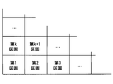
基本地図データは、図2及び図3に示すように、地図収録地域を複数区画に分割してなる区画毎の地図データを備える。以下では、基本地図データが備える区画毎の地図データを、区画データとも記載する。これらの区画データの一群は、区画の地理的配置に従う順序で、対応する区画データが配列されたデータ群として構成される。便宜上、配列順がk番目の区画データのことを第k区画データと表現する。例えば第1区画データとは、配列順が1番目の区画データを指す。なお、kは自然数である。区画の数は適宜設計されればよく、ここでは一例として58000とする。
各区画データは、対応する区画内の地図要素の位置等を示す地図データとして構成される。各区画には、基準点が設定されている。区画データは、その区画に設定されている基準点の位置座標を示す基準座標データを備える。ここでの位置座標とは、所定の三次元座標系(例えばWGS-84座標系)における座標(つまり絶対座標)である。もちろん、基準点の座標は、例えばITRF座標系等といった、WGS-84座標系以外の座標系で表されていてもよい。なお、WGSはWorld Geodetic Systemの略であり、ITRFは、International Terrestrial Reference Frameの略である。便宜上、三次元座標系を構成する3つの軸方向をX軸方向、Y軸方向、Z軸方向と称する。
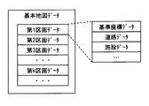
また、区画データは、基準座標データに加えて、その区画内に設けられている道路網についてのデータ(つまり道路データ)や、施設データなどを備える。道路データは、例えば、ノード毎のノードデータと、リンク毎のリンクデータと、を用いて構成されていれば良い。ノードとは、交差点などといった道路同士の結束点又は終端点である。リンクとは、ノード間を結ぶ道路を指す。ノードデータは、ノード毎に設定されている固有の番号(以降、ノードID)や、ノードの種別、ノードに接続するリンクについての情報等が記述される。
リンクデータは、例えば図4に示すように、メタデータ、形状データ、道路標識データ、信号機データ、道路標示データを備える。メタデータは、リンク毎に設定されている固有の番号(以降、リンクID)や、リンクの長さを示すリンク長、リンクの始端に相当するノードのID、リンクの終端に相当するノードのID、道路種別等を示すデータである。形状データは、リンクの形状を示すデータであって、リンク上に設定された複数地点の位置を表す座標群のデータである。道路標識データは、道路標識の設置位置を示すデータである。信号機データは、信号機の有無や設置位置を示すデータである。道路標示データは、道路標示の設置位置を示すデータである。
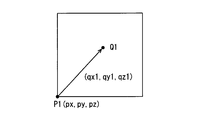
リンク形状を示すためにリンク上に設定されている複数の地点や、信号機、道路標識、道路標示等といった、種々の地図要素の位置は、図5に示すように、基準点に対する相対位置を示す相対座標で表されている。なお、図5に示すP1は、第1区画に設定されている基準点を表しており、Q1は、第1区画に存在する或る地図要素を表している。第1区画の基準点P1の位置情報は絶対座標によって表現される一方、地図要素Q1の位置は、基準点P1に対する相対座標で表される。仮に基準点P1の座標を(px,py,pz)であり、地図要素Q1の位置情報が(qx1,qy1,qz1)である場合、地図要素Q1の絶対座標は、それらを結合した座標、すばわち(px+qx1,py+qy1,pz+qz1)となる。
なお、本実施形態では基準座標データは区画データ内に収容されているものとするが、これに限らない。基準座標データは、区画データとは別テーブルで格納されていてもよい。その場合、各区画データは、当該区画に対応する基準座標データを参照するための参照先情報を備えているものとする。
基準座標データや、各地図要素の相対座標を表すデータといった、基本地図データが備える種々の地図要素の位置情報は、行政機関や地図作成業者(以降、地図管理者)が測量して特定されたものである。基本地図データには、区画毎の地図データの他に、当該基本地図データを作成した時期(換言すれば測量を実施した時期)を示すデータが含まれているものとする。たとえば元期などのデータが含まれている。
なお、図5では基準点を区画の紙面左下に相当する位置に配置している態様を例示しているが、これに限らない。基準点は、区画の中心に設定されていてもよい。また、区画内において代表的な構造物が存在する地点を基準点に設定しても良い。基準点とする位置は適宜設計されれば良い。また、図5では区画を矩形状に設定する態様を開示しているが、区画の輪郭形状は矩形に限らない。三角形状や六角形状など、矩形以外の多角形状であってもよい。
また、区画データは、階層的な構造となっていても良い。例えば1つの区画をさらに16区画に細分化し、1つの区画が16個のサブ区画データを備えていてもよい。その場合、地図収録地域に設定されるサブ区画の数は、58000×16=928000となる。また、サブ区画の概念を導入する場合、地図要素毎の相対座標(つまり位置情報)は、サブ区画の地図データに収録されていればよい。
(車両用ユニット1の構成)
ここでは車両用ユニット1の具体的な構成について述べる。車両用ユニット1は、図6に示すように、車両内に構築された通信ネットワーク(つまりLAN:Local Area Network)5を介して、自動運転ECU6や周辺監視システム7等と相互通信可能に構成されている。以降では、車両用ユニット1が搭載されている車両のことを自車両とも記載する。
ここでは車両用ユニット1の具体的な構成について述べる。車両用ユニット1は、図6に示すように、車両内に構築された通信ネットワーク(つまりLAN:Local Area Network)5を介して、自動運転ECU6や周辺監視システム7等と相互通信可能に構成されている。以降では、車両用ユニット1が搭載されている車両のことを自車両とも記載する。
自動運転ECU6は、自動運転アプリがインストールされたコンピュータを備えるECUである。自動運転ECU6は、車両用ユニット1から提供される地図データ(具体的には補正済み地図データ)を用いて、ユーザによって設定されている走行計画(換言すれば走行予定経路)に沿って自車両が走行するように、操舵、加速、減速等を自動的に実行する。なお、自動運転ECU6と車両用ユニット1とは前述の通り一体化されていても良い。つまり、車両用ユニット1が自動運転機能を提供するように構成されていても良い。
周辺監視システム7は、自車両周辺に所定の検出対象物が存在することを検出するとともに、検出した物体(以降、検出物)の自車両に対する相対位置を特定するシステムである。検出対象物とは、例えば、道路標識や、道路標示、信号機、ガードレール、電柱、縁石、輪留めなどである。道路標識や道路標示などいった、基本地図データにおいて地図要素として登録されている路上設置物の一部又は全部が検出対象物として登録されていれば良い。検出対象物の具体的な内容は、適宜設計されれば良い。周辺監視システム7は、周辺監視センサ(SENS)71と、環境認識ECU(ENV_ECU)72と、を用いて実現される。
周辺監視センサ71は、検出対象物を検出するためのセンサである。周辺監視センサ71としては、例えば、車両外部の所定範囲を撮像する周辺監視カメラ、車両外部の所定範囲に探査波を送信するミリ波レーダ,LIDAR(Light Detection and Ranging/Laser Imaging Detection and Ranging)等を採用することができる。ここでは一例として周辺監視センサ71は、周辺監視カメラとする。周辺監視センサ71としての周辺監視カメラは、逐次撮像する撮像画像を環境認識ECU72へ逐次出力する。
環境認識ECU72は、周辺監視センサ71としての周辺監視カメラから提供される画像データに対して、周知の画像認識処理を実施し、道路標識等の検出対象物を検出する。また、その検出物の自車両に対する相対位置を特定する。周辺監視システム7の検出結果は、LAN5を介して車両用ユニット1に逐次(例えば100ミリ秒毎に)提供される。
また、車両用ユニット1は、通信ドライバ11、GNSS受信機12、広域通信部13、地図データ記憶部14、及び車両側制御部15を備える。通信ドライバ11は、車両側制御部15が、自動運転ECU6や周辺監視システム7といった、LAN5に接続する他の構成と相互通信するための構成である。通信ドライバ11は車両側制御部15と相互通信可能に構成されている。
GNSS受信機12は、GNSS衛星4から送信される電波を受信する。GNSS受信機12は、GNSS衛星を4機以上捕捉している場合、各GNSS衛星から受信した電波に基づいて、GNSS受信機12の現在位置を逐次算出(換言すれば検出)する。GNSS衛星4から送信される電波が航法信号に相当する。
GNSS受信機12が検出した現在位置は、所定の三次元座標系における座標で表される。ここでは一例として、現在位置はWGS-84座標系で表されるものとする。もちろん、現在位置は例えばITRF座標系等のWGS-84座標系以外の座標系で表されていてもよい。なお、基本地図データが備える基準座標データや、各地図要素の基準点相対位置は、GNSS受信機12が採用している測地系と同じ測地系で表現されていることが好ましい。同一の測地系であれば、座標変換のための行列演算が省略できるためである。GNSS受信機12が検出した現在位置を示す情報は車両側制御部15に逐次提供される。GNSS受信機12が車両位置検出器に相当する。
広域通信部13は、広域通信網3に接続し、センタ2と通信するための通信モジュールである。広域通信部13は、車両側制御部15から入力されたデータを変調して、センタ2に送信する。また、センタ2から送信されたデータを受信して車両側制御部15に提供する。
地図データ記憶部14は、上述した基本地図データを記憶している不揮発性の記憶媒体である。地図データ記憶部14は、例えばハードディスクドライブやフラッシュメモリ等を用いて実現されれば良い。地図データ記憶部14は、車両側制御部15によってデータの読み出しが可能に構成されている。なお、本実施形態では地図データ記憶部14には、全ての区画についてのデータが格納されているものとするが、これに限らない。地図データ記憶部14にはユーザが利用する範囲の区画データが保存されていればよい。そのため、他の態様としては、一部の区画についての地図データのみが保存されていても良い。
車両側制御部15は、通常のコンピュータとして構成されており、中央演算装置としてCPU151、揮発性の記憶媒体であるRAM(Random Access Memory)152、書き換え可能な不揮発性の記憶媒体であるROM(Read Only Memory)153、I/O、及びこれらの構成を接続するバスラインなどを備えている。ROM153には、通常のコンピュータを本実施形態における車両側制御部15として機能させるためのプログラム(以降、車両用プログラム)等が格納されている。
なお、上述の車両用プログラムは、非遷移的実体的記録媒体(non-transitory tangible storage medium)に格納されていればよい。CPU151が車両用プログラムを実行することは、車両用プログラムに対応する方法が実行されることに相当する。この車両側制御部15が備える機能については次に説明する。
(車両側制御部15の機能)
車両側制御部15は、CPU151がROM153に格納されている車両用プログラムを実行することで図7に示す種々の機能を提供する。すなわち、車両側制御部15は機能ブロックとして、位置情報取得部F1、周辺情報取得部F2、地図読出部F3、マップ上位置特定部F4、検出物座標特定部F5、乖離量特定部F6、乖離量データ送信部F7、受信データ取得部F8、及び補正地図生成部F9を備える。
車両側制御部15は、CPU151がROM153に格納されている車両用プログラムを実行することで図7に示す種々の機能を提供する。すなわち、車両側制御部15は機能ブロックとして、位置情報取得部F1、周辺情報取得部F2、地図読出部F3、マップ上位置特定部F4、検出物座標特定部F5、乖離量特定部F6、乖離量データ送信部F7、受信データ取得部F8、及び補正地図生成部F9を備える。
また、車両側制御部15は、不揮発性であって書き換え可能な記憶媒体を用いて実現される構成として、補正用データ記憶部M1と、更新データ記憶部M2とを備える。補正用データ記憶部M1や更新データ記憶部M2は、例えばROM153が備える記憶領域の一部を用いて実現されれば良い。
位置情報取得部F1は、GNSS受信機12から車両用ユニット1の現在位置を示す座標(以降、検出自車位置)を逐次取得する。位置情報取得部F1が取得した検出自車位置は、取得時刻(換言すれば検出時刻)を示すタイムスタンプを付与してRAM152に一定時間保存される。
複数時点における検出自車位置は、例えば、最新のデータが先頭となるように時系列順にソートされてRAM152に保存されればよい。RAM152に保存されている検出自車位置は、地図読出部F3やマップ上位置特定部F4等によって参照される。なお、本実施形態ではGNSS受信機12が出力する座標情報をそのまま自車両の座標情報として採用するものとするが、これに限らない。自車両内におけるGNSS受信機12の設置位置に応じて、GNSS受信機12の検出結果を補正した座標を自車両の現在位置を示す座標として用いてもよい。例えば検出自車位置が、自車両の中心の位置を示すようにGNSS受信機12の検出結果を補正して用いてもよい。
周辺情報取得部F2は、周辺監視システム7から、自車両周辺に存在する検出対象物の相対位置を示すデータを取得する。なお、本実施形態では、路上設置物が地図要素として基本地図データに収録されており、かつ、路上設置物は周辺監視システム7の検出対象物として設定されている。そのため、周辺監視システム7から提供されるデータは、自車両周辺に存在しており、かつ、周辺監視システム7によって検出されている路上設置物(以降、検出物)の相対位置を示すデータとして機能する。
地図読出部F3は、位置情報取得部F1が取得している検出自車位置に基づき、自車両周辺の地図データ(以降、周辺地図データ)を地図データ記憶部14から読み出す。例えば地図読出部F3は、周辺地図データとして、検出自車位置を含む区画の地図データを読み出す。検出自車位置を含む区画とは、自車両が走行している区画(以降、走行区画)に相当する。地図読出部F3が周辺地図データ取得部に相当し、走行区画に対応する区画データが走行区画データに相当する。
なお、他の態様として地図読出部F3は、走行区画の地図データだけでなく、走行区画に隣接する区画や、自車両の進行方向に存在する区画の地図データを周辺地図データとして読み出しても良い。また、自車両が走行する予定の経路情報を取得できる場合には、その走行予定経路が通る区画の地図データを読み出しても良い。走行予定経路情報はLAN5に接続している他のECUから取得すればよい。走行予定経路情報は、例えば、経路案内処理等を実施するナビゲーションECUから取得することができる。
マップ上位置特定部F4は、周知のマップマッチング処理を実施し、基本地図データ上における自車両の位置(以降、マップ上自車位置)を特定する構成である。具体的には、複数時点における検出自車位置を時系列順に並べた時系列データに基づいて自車両の走行軌跡を特定し、その特定した走行軌跡と周辺地図データから得た道路形状とを比較することによって、マップ上自車位置を特定する。そして、マップ上位置特定部F4は、マップ上自車位置を示す座標情報を乖離量特定部F6に提供する。マップ上自車位置は、絶対座標で表される。
なお、車両用ユニット1が自車両の走行速度や進行方向、車両に作用している加速度等の情報を取得できる場合には、それらの情報を用いたマップマッチング処理を実施してもよい。走行速度等の情報は、LAN5を介して所定のECUやセンサから取得すればよい。マップ上位置特定部F4がマップ上自車位置特定部に相当する。
なお、他の態様としてマップ上位置特定部F4は、後述する検出物座標特定部F5が特定した路上設置物のマップ上検出物座標から、自車両に対する当該路上設置物の相対位置を逆算することによって、マップ上自車位置を特定しても良い。
検出物座標特定部F5は、周辺情報取得部F2が取得した検出物の自車両に対する相対位置と、検出自車位置に基づいて、検出物の絶対座標を算出(すなわち特定)する。そして、算出した検出物の絶対座標(以降、検出物座標)を、検出物の種別(例えば制限速度標識等)を示す要素種別情報と対応付けて乖離量特定部F6に提供する。
乖離量特定部F6は、検出自車位置に基づいて、基本地図データに示されている地図要素の位置と、実際の地図要素の位置とのずれ度合い(つまり乖離量)を特定する構成である。乖離量特定部F6は、第1の方法として、検出自車位置とマップ上自車位置との差を算出し、その算出した差を乖離量として採用する。
乖離量は、基本地図データにおける地図要素の位置の表現形式として採用されている三次元座標系のパラメータで表されれば良い。例えば検出自車位置が(vax,vay,vaz)であり、マップ上自車位置が(vbx,vby,vbz)である場合には、乖離量は、(vax-vbx,vay-vby,vaz-vbz)となる。つまり、乖離量はX軸方向の差、Y軸方向の差、Z軸方向の差として表現される。
また、乖離量特定部F6は、第2の方法として、検出物座標特定部F5から提供される検出物座標及び要素種別情報を用いて乖離量を特定する。具体的には、検出物座標及び要素種別情報に基づいて、基本地図データに示されている複数の路上設置物の中から、検出物に対応する(換言すれば同一の)路上設置物を特定し、その路上設置物の基本地図データ上における位置座標(以降、マップ上検出物座標)を特定する。マップ上検出物座標は、基準点の絶対座標と、路上設置物に設定されている相対座標を結合させた座標である。そして、マップ上検出物座標と、検出物座標特定部F5が特定している検出物座標との差を、乖離量として算出する。
なお、本実施形態の乖離量特定部F6は、第1の方法と第2の方法の両方を実施可能に構成されているものとするが、これに限らない。何れか一方の方法のみ実施可能に構成されていても良い。
乖離量特定部F6が特定した乖離量は、乖離量データ送信部F7に提供される。また、本実施形態ではより好ましい態様として、乖離量特定部F6が特定した乖離量は、特定した日時を示す特定日時情報や、乖離量を特定した時点での自車両の位置を示す特定場所情報と対応付けられて補正用データ記憶部M1に保存しておくものとする。
乖離量特定部F6による乖離量の特定処理(以降、乖離量特定処理)は、所定の特定処理実施条件が充足された場合に実施されれば良い。例えば、或る区画内での走行距離が所定の特定許可距離以上となった時点で実施すればよい。特定許可距離は、走行区画内での走行軌跡に基づいてマップマッチングが可能な距離とすればよい。本実施形態では一例として特定処理実施条件は、1日に1つの区画に対して乖離量特定処理を実施する回数は1回となるように設計されているものとする。
なお、他の態様として特定処理実施条件は、同一区画についての乖離量特定処理を1日のうちに複数回実施可能に設計されていても良い。例えば、同一区画内において特定許可距離だけ走行する度に乖離量特定処理を実施するように設定されていても良い。その他、乖離量特定処理は一定時間おきに実施するように構成しても良い。1つの区画に対して乖離量特定処理を実施する回数や間隔は適宜設計されればよい。なお、同一区画についての乖離量特定処理は、前回実施してから一定時間(例えば1週間)以上経過している場合にのみ実施するように、特定処理実施条件を設定してもよい。
乖離量データ送信部F7は、広域通信部13と協働して、乖離量特定部F6が特定した乖離量を示す乖離量データをセンタ2に送信する。具体的には、乖離量データを広域通信部13に出力し、センタ2を宛先とする乖離量データを収容した通信パケットを送信させる。乖離量データには、乖離量の他、自車両が走行している区画を示す区画番号が含まれる。乖離量データに示される区画番号は、当該乖離量データが何れの区画についての乖離量データであるのかを示す。区画番号が区画情報に相当する。
また、乖離量データには、乖離量や区画番号の他、車両IDや、特定日時情報、特定場所情報等が含まれていることが好ましい。本実施形態では、乖離量データには、区画番号、乖離量、車両ID、特定日時情報、及び特定場所情報が含まれているものとする。
なお、本実施形態における乖離量データ送信部F7は、乖離量が特定される度に乖離量データを送信する。他の態様として、特定処理実施条件が、乖離量特定処理が1日に複数回実施可能に設計されている場合には、1つの区画についての乖離量データを1日に複数回送信してもよい。また、1日のうちに同一区画に対する乖離量が複数回算出されるように構成されている場合、乖離量データ送信部F7は同一区画に対して算出された複数の乖離量を平均化又は中央値化したデータを乖離量データとして送信するように構成されていてもよい。
受信データ取得部F8は、センタ2から車両用ユニット1宛に配信されて、広域通信部13が受信したデータを取得する。例えば受信データ取得部F8は、補正用データや更新データを取得する。受信データ取得部F8がデータ取得部に相当する。
補正用データは、車両用ユニット1がセンタ2に送信した乖離量データに基づいてセンタ2が生成した、基本地図データに示されている基準点の位置座標(つまり基準座標データ)の補正量を示すデータである。補正用データは、区画毎(換言すれば基準点毎)に用意される。そのため、補正用データは、補正量だけでなく、区画番号も含まれている。区画番号は、受信した補正用データが何れの区画の基準点についての補正用データであるのかを示す役割を担う。
更新データは、例えばリンクやノード、施設、道路標識等といった地図要素の削除/追加を示すデータである。つまり、基本地図データを作成した時点からの変更部分を表す地図データである。なお、更新地図データにおいて追加される地図要素の位置情報は、基準点を基準とする相対座標で表される。
更新データも区画毎に配信されればよい。また、更新データには、当該更新データが生成された年月日や、バージョン情報といった、データの新しさを示すデータが付与されているものとする。なお、更新データは、基本地図データに対する差分を表すものであってもよいし、前バージョンからの差分を表すものであっても良い。
受信データ取得部F8は、補正用データを取得した場合、当該データを補正用データ記憶部M1に保存する。また、更新データを取得した場合、当該データを更新データ記憶部M2に保存する。補正用データ記憶部M1及び更新データ記憶部M2のそれぞれは、受信データ取得部F8及び補正地図生成部F9のそれぞれによって参照可能に構成されている。
補正地図生成部F9は、補正用データ記憶部M1に保存されている補正用データと、基本地図データとを用いて、基本地図データに示される位置座標と実際の位置座標との誤差が抑制された補正済み地図データを生成する。
具体的には、補正地図生成部F9は、補正済み地図データの生成の対象とする区画(以降、対象区画)の補正用データを補正用データ記憶部M1から読み出し、対象区画の基準点の位置座標を補正する。そして、その補正した基準点の位置座標と、対象区画が備える地図要素毎の相対座標とを結合する(換言すれば足し合わせる)ことによって、地図要素毎の絶対座標を示す補正済み地図データを生成する。
このようにして生成される補正済み地図データは、基本地図データが示す地図要素の位置を、補正量だけスライド(換言すれば移動)させた地図データに相当する。補正済み地図データは、区画毎に生成されれば良い。生成された補正済み地図データは、自動運転ECU6などの地図データの要求元に提供される。換言すれば、補正地図生成部F9は、アプリケーションソフトウェアからの要求に基づいて、要求された区画の補正済み地図データを生成し、提供する。
なお、補正済み地図データの生成時には、更新データが示す地図要素の変更も反映される。基本地図データが備える対象区画の地図データに、更新データを結合することによって、地図要素の追加/削除を反映する。その後に、上述した手順の処理が実施されれば良い。補正地図生成部F9が車両側補正地図生成部に相当する。
(センタ2の構成)
次に、センタ2の構成について述べる。センタ2は、図8に示すように広域通信部21、センタ側制御部22、乖離量記憶部23、補正量記憶部24、及び更新データ記憶部25を備える。センタ側制御部22は、広域通信部21、乖離量記憶部23、補正量記憶部24、及び更新データ記憶部25のそれぞれと相互通信可能に接続されている。
次に、センタ2の構成について述べる。センタ2は、図8に示すように広域通信部21、センタ側制御部22、乖離量記憶部23、補正量記憶部24、及び更新データ記憶部25を備える。センタ側制御部22は、広域通信部21、乖離量記憶部23、補正量記憶部24、及び更新データ記憶部25のそれぞれと相互通信可能に接続されている。
広域通信部21は、車両用ユニット1と広域通信を実施するための通信モジュールである。広域通信部21は、受信したデータをセンタ側制御部22に出力するとともに、センタ側制御部22から入力されたデータを変調して広域通信網3に出力する。広域通信網3に出力された通信パケットは、車両用ユニット1に伝送される。
センタ側制御部22は、センタ2全体の動作を制御する役割を担う構成である。センタ側制御部22は、コンピュータとして構成されている。つまり、CPU、RAM、ROM、I/O、及びこれらの構成を接続するバスラインなどを備える。センタ側制御部22は、機能ブロックとして、格納処理部221、補正量算出部222、及び配信処理部223を備える。格納処理部221、補正量算出部222、及び配信処理部223は、図示しないCPUが所定のプログラムを実行することによって実現されればよい。また、他の態様として、ICなどのハードウェア部材を用いて実現されていても良い。
格納処理部221は、車両用ユニット1から送信(換言すればアップロード)されてくる乖離量データを、乖離量記憶部23に格納していく。具体的には、乖離量データに示される区画番号、乖離量、車両ID、特定日時情報、及び特定場所情報を互いに対応付けて乖離量記憶部23に保存する。
乖離量記憶部23は、書き換え可能な不揮発性の記憶媒体を用いて実現される。乖離量記憶部23内において複数の乖離量データは、区画番号毎(換言すれば区画毎)に区別して保存されればよい。乖離量データは、例えば特定日時情報が最新のものが先頭となるように時系列順にソートされて保存されれば良い。
補正量算出部222は、区画毎の乖離量データに基づいて区画毎の基準点の補正量を算出し、補正量記憶部24に保存する。或る基準点についての補正量とは、基準座標データとして基本地図データに示されている当該基準点の位置座標を、実際の位置座標に一致させるための移動量に相当する。基準点の補正量を示すデータに区画番号を付与したデータが補正用データに相当する。
本実施形態の補正量算出部222は一例として、或る1つの区画についての補正量を算出する際、その対象とする区画(以降、対象区画)についての複数の乖離量を用いて補正量を決定する。具体的には、補正量算出部222は、図9に示すように、乖離量記憶部23に保存されている対象区画についての複数の乖離量を、基準点を原点とする三次元座標系の座標と見なしてプロットした点群の重心の座標とする。
なお、図9は第k区画の補正量を算出する際の補正量算出部222の作動を概念的に表した図である。図9に示す中抜きの点は、第k区画に対応付けられている乖離量に対応する点である。図9に示すように、第k区画の補正量を決定する際に用いる三次元座標系の原点は、第k区画の基準点Pkに相当する。Pgは、複数の乖離量に対応する点群の重心を表している。原点から重心Pgに向かうベクトルΔPk(dx,dy,dz)が補正量に相当する。補正量は、X軸方向の補正値、Y軸方向の補正値、Z軸方向の補正値を1組とするデータとして表現される。
なお、他の態様として、補正量の軸方向毎の値は、複数の乖離量の軸方向毎の値を平均値や中央値としてもよい。また、補正量算出部222は、任意の或る1時点において特定された1つの乖離量をそのまま補正量として採用するように構成されてもよい。
或る区画についての補正量を算出するための母集団として用いる乖離量は、特定日時情報が示す日時が、直近の所定期間(例えば3ヶ月や半年)内となっている乖離量とすることが好ましい。仮に半年以上も過去のデータを母集団に入れると、その間の地殻変動に応じたずれがノイズとして含まれてしまうためである。換言すれば、上記構成によれば、より精度良い補正用データを生成することができる。
区画毎の補正用データは、所定の更新周期で(例えば3ヶ月毎に)生成されれば良い。つまり、各区画の補正用データは所定の更新周期で更新されていく。なお、所定の更新周期で全ての区画の補正用データを一斉に更新してもよいし、区画毎にずれたタイミングで実施しても良い。また、地図管理者からの入力操作に基づいて(つまり手動操作で)、補正用データの生成を実施するように構成されていてもよい。
補正量記憶部24は、書き換え可能な不揮発性の記憶媒体を用いて実現されている。補正量記憶部24内において区画毎の補正用データは、当該データを生成した日付を示す更新日付情報と対応付けられて保存されている。更新データ記憶部25もまた、書き換え可能な不揮発性の記憶媒体を用いて実現されている。更新データ記憶部25には更新データが保存されている。更新データ自体は、行政機関や地図作成業者によって生成されればよい。
配信処理部223は、広域通信部21と協働して、補正用データを配信する。補正用データの配信は、車両用ユニット1からの要求に基づいて実施されれば良い。また、他の態様として、補正用データの更新を実施する度に、配信しても良い。補正用データは、区画単位で配信してもよいし、全ての区画の補正用データを一括して(つまりパッケージ化して)配信しても良い。
補正用データは、圧縮処理を施した状態で配信してもよい。ただし、試算によると全区画分の補正用データの合計サイズは9MB程度におさまるため、圧縮する必要性は高くない。故に、本実施形態では、圧縮せずに配信することとする。なお、補正用データの配布方法は、通信による配布に限らない。DVD等の実体を有する記憶媒体を用いてカー用品ショップやディーラ等で配布されても良い。配信処理部223は、更新データについても、所定のタイミングで車両用ユニット1に配信する。
(実施形態の効果)
図10に示すように地図要素の位置座標(換言すれば地球上での位置)は、地殻変動によって経時的に変化していく。そのため、基本地図データに示される各地点の位置座標と実際の位置座標との誤差を、自動運転等のアプリケーションで利用可能な範囲内に収めた状態を維持するためには、相対的に頻繁に位置情報の更新が必要となる。
図10に示すように地図要素の位置座標(換言すれば地球上での位置)は、地殻変動によって経時的に変化していく。そのため、基本地図データに示される各地点の位置座標と実際の位置座標との誤差を、自動運転等のアプリケーションで利用可能な範囲内に収めた状態を維持するためには、相対的に頻繁に位置情報の更新が必要となる。
上述した構成では、種々の地図要素の位置情報を、当該地図要素が属する区画に設定されている基準点に対する相対位置を示す相対座標で表している。そのため、或る区画の位置が地殻変動によって平行移動した場合であっても、基準点の位置座標を実際の位置座標と合致するように補正することで、当該区画データが示す地図要素の位置を実際の位置に合わせることができる。つまり、地図要素毎に位置座標のデータを更新する手間を低減することができる。
また、基本地図データが備える基準点の位置座標を実際の位置座標に合致させるための補正量は、車両用ユニット1が検出する乖離量を用いた演算処理によって定まる。そのため、補正量を特定するために、地図データの管理者(例えば地図作成業者)が現地に赴いて測量作業を実施する必要がない。したがって、上記構成によれば、実際の位置座標と地図データに示される位置座標との誤差が抑制された地図データを低コストに提供することができる。
さらに、以上の構成では、センタ2が複数の車両用ユニット1から提供される複数の乖離量を用いて1つの基準点に対する補正量を算出する。そのような構成によれば、車両用ユニット1毎の誤差が抑制された、より精度よい補正量が利用可能となる。その結果、車両用ユニット1が生成する補正済み地図データは、実際の位置座標と地図データに示される位置座標との誤差がより一層抑制された地図データとなる。
また、上記構成において補正用データとして送信する情報は主として基準点の補正量を示すデータであり、地図要素毎のデータは送信する必要がない。したがって、センタ2と車両用ユニット1との通信量及び通信料を抑制することができる。
さらに、上述した構成によれば車両用ユニット1は、センタ2から任意の区画についての補正用データを取得するため、自分自身が未だ走行していない区画についての補正用データも取得することができる。自分自身が未だ走行していない区画についての補正用データとは、他の車両用ユニット1が提供した乖離量に基づいて算出された補正用データである。つまり、センタ2を介して、複数の車両用ユニット1は種々の区画の補正用データを共有することができる。
なお、上述した構成によれば、地図データの管理者は、実際の位置座標と地図データに示される位置座標との誤差が抑制された地図データを低コストに提供できるため、最終的に、ユーザが補正済み地図データを利用するための費用も低減することができる。
また、地図データが備える基準点の位置座標を実際の位置座標に合致させるための補正量は、車両用ユニットが備える乖離量特定部が特定した乖離量を用いた演算処理によって定まる。そのため、補正量を特定するために地図データの管理者(例えば地図作成業者)が現地に赴いて測量作業を実施する必要がない。
なお、前述の実施形態で述べた部材と同一の機能を有する部材については、同一の符号を付し、その説明を省略する。また、構成の一部のみに言及している場合、他の部分については先に説明した実施形態の構成を適用することができる。
(変形例1)
車両用ユニット1は、乖離量データとして、乖離量を特定する際に用いた自車位置情報の検出精度を示す情報(以降、精度指標情報)を含む乖離量データを送信することが好ましい。精度指標情報とは、例えば、車両用ユニット1が捕捉しているGNSS衛星4の数や、GNSS衛星4毎の受信電波のSN比である。ここでは一例として、測位演算に用いたGNSS衛星4のSN比を精度指標情報として採用する。精度指標情報は乖離量特定部F6が生成すればよい。
車両用ユニット1は、乖離量データとして、乖離量を特定する際に用いた自車位置情報の検出精度を示す情報(以降、精度指標情報)を含む乖離量データを送信することが好ましい。精度指標情報とは、例えば、車両用ユニット1が捕捉しているGNSS衛星4の数や、GNSS衛星4毎の受信電波のSN比である。ここでは一例として、測位演算に用いたGNSS衛星4のSN比を精度指標情報として採用する。精度指標情報は乖離量特定部F6が生成すればよい。
そのような構成によれば、補正量算出部222は、乖離量に対応付けられている精度指標情報を参照することで、当該乖離量の信頼度を評価することができる。乖離量がGNSS受信機12の検出されている自車位置情報を用いて算出されるため、当然、GNSS衛星4からの電波の受信状況が良好な状況において特定された乖離量は、GNSS衛星4からの電波の受信状況が悪い状況で特定された乖離量よりも信頼度が高い。
変形例1における補正量算出部222は、乖離量記憶部23に保存されている乖離量毎の信頼度を評価し、複数の車両用ユニット1から提供された複数の乖離量のうち、相対的に信頼度が高い乖離量を優先的に用いて補正量を算出する。例えば、補正量算出部222がN個(Nは自然数)の乖離量を用いて補正量を算出するように構成されている場合には、補正量を算出するための母集団として、信頼度が高い乖離量を優先的に採用する。そのような構成によれば、補正量をより精度良く算出することができる。
なお、信頼度が高い乖離量を優先的に用いて補正量を算出する態様には、信頼度が高い乖離量のみを用いて補正量を算出する態様を含む。信頼性が高いか否かは、SN比が所定の閾値以上となっているか否かなど、精度指標情報の種類に応じた基準を用いて判定すればよい。
(変形例2)
図11に示すように地図データ提供システム100は、車両用ユニット1とは異なる通信端末8を備え、センタ2は、通信端末8に対して補正済み地図データを配信するように構成されていてもよい。そのような構成によれば、車両用ユニット1以外の通信端末8も、補正済み地図データを利用することができる。
図11に示すように地図データ提供システム100は、車両用ユニット1とは異なる通信端末8を備え、センタ2は、通信端末8に対して補正済み地図データを配信するように構成されていてもよい。そのような構成によれば、車両用ユニット1以外の通信端末8も、補正済み地図データを利用することができる。
なお、ここでの通信端末8とは、広域通信機能及びGNSS受信機を備えている装置である。例えばスマートフォンや、タブレット端末、ポータブルナビゲーション装置などを通信端末8として採用することができる。通信端末が地図利用端末に相当する。
この変形例2におけるセンタ2は、例えば図12に示すように、地図データ記憶部26及び補正地図生成部224を備える。地図データ記憶部26は、基本地図データが保存されているデータベースである。補正地図生成部224は、前述の補正地図生成部F9に相当する構成である。補正地図生成部224がセンタ側補正地図生成部に相当する。
センタ2は、通信端末8からの要求に基づき、通信端末8から要求された区画の補正済み地図データを生成して送信する。例えば、通信端末8が存在している区画の補正済み地図データを生成して送信する。この変形例2の構成によれば、車両用ユニット1を備えない車両も、通信端末8を備えていれば補正済み地図データを利用可能となる。車両用ユニット1もまた、センタ2から補正済み地図データを取得して利用することができる。
なお、この変形例2の構成によれば、車両用ユニット1は、補正地図生成部F9を備えている必要はない。そのため、車両側制御部15での演算処理負荷を低減することができる。
(変形例3)
以上では、地図データ提供システム100がセンタ2を備える構成を開示したが、これに限らない。図13に示すように地図データ提供システム100はセンタ2を備えていなくても良い。そのような地図データ提供システム100を変形例3として、以下説明する。
以上では、地図データ提供システム100がセンタ2を備える構成を開示したが、これに限らない。図13に示すように地図データ提供システム100はセンタ2を備えていなくても良い。そのような地図データ提供システム100を変形例3として、以下説明する。
変形例3における車両側制御部15は、図14に示すように、補正量算出部F10を備える。補正量算出部F10は、前述の補正量算出部222に相当する構成である。補正量算出部F10は、センタ2と同様に乖離量特定部F6が特定した複数の乖離量を用いて補正量を算出する。なお、他の態様として、任意の或る1時点において特定された1つの乖離量をそのまま補正量として採用するように構成されてもよい。
補正量算出部F10が算出した補正量は、補正用データ記憶部M1に保存される。補正地図生成部F9は、前述の実施形態と同様に、補正用データ記憶部M1に保存されている補正量を用いて補正済み地図データを生成して所定のアプリケーションに提供する。
このような構成によれば、車両用ユニット1単体で補正済み地図データを提供することができる。なお、この変形例3における車両用ユニット1は、広域通信部13を備えている必要はない。
(変形例4)
変形例3の車両用ユニット1が備える補正量算出部F10は、或る区画についての補正量を、その区画に隣接する区画に対して算出している補正量を用いて算出しても良い。例えば、第2区画に対する補正量を、第1区画と第3区画のそれぞれに対して設定している補正量の軸方向毎の値の平均値とする。
変形例3の車両用ユニット1が備える補正量算出部F10は、或る区画についての補正量を、その区画に隣接する区画に対して算出している補正量を用いて算出しても良い。例えば、第2区画に対する補正量を、第1区画と第3区画のそれぞれに対して設定している補正量の軸方向毎の値の平均値とする。
そのような構成によれば、未だ乖離量を取得できていない区画(以降、未設定区画)が存在し、かつ、その隣接する区画についての補正量を算出できている場合には、当該未設定区画に対する補正量を設定することができる。なお、変形例4として上述した方法は、センタ2が備える補正量算出部222にも適用できる。
(変形例5)
変形例3の車両用ユニット1が備える補正量算出部F10は、区画毎の補正量を、単位期間当りの地殻移動量の想定値と、最後に補正量の算出してからの経過時間と、に基づいて修正して用いてもよい。例えば1ヶ月当りの地殻変動量の想定値が(Δxm,Δym,Δzm)であり、かつ、最後に補正量を算出してから2ヶ月経過している区間が存在する場合、その区間の補正量は、(dx+2×Δxm,dy+2×Δym,dz+2×Δzm)として用いる。なお、(dx,dy,dz)が修正前の補正量を表している。
変形例3の車両用ユニット1が備える補正量算出部F10は、区画毎の補正量を、単位期間当りの地殻移動量の想定値と、最後に補正量の算出してからの経過時間と、に基づいて修正して用いてもよい。例えば1ヶ月当りの地殻変動量の想定値が(Δxm,Δym,Δzm)であり、かつ、最後に補正量を算出してから2ヶ月経過している区間が存在する場合、その区間の補正量は、(dx+2×Δxm,dy+2×Δym,dz+2×Δzm)として用いる。なお、(dx,dy,dz)が修正前の補正量を表している。
このような構成によれば、過去に行ったことがあって、暫く走行していない区画についても補正済み地図データを生成して利用することができる。なお、変形例5として上述した方法は、センタ2が備える補正量算出部222にも適用できる。
上記の複数の部の各々あるいは組合わさったものは、(i) ハードウエアユニット(例えば、コンピュータ)と組み合わさったソフトウエアの部のみならず、(ii) ハードウエア(例えば、集積回路、配線論理回路)の部として、関連する装置の機能を含みあるいは含まずに実現できる。さらに、ハードウエアの部は、マイクロコンピュータの内部に構成されることもできる。
本開示は、実施例に準拠して記述されたが、本開示は当該実施例や構造に限定されるものではないと理解される。本開示は、様々な変形例や均等範囲内の変形をも包含する。加えて、様々な組み合わせや形態、さらには、それらに一要素のみ、それ以上、あるいはそれ以下、を含む他の組み合わせや形態をも、本開示の範畴や思想範囲に入るものである。
Claims (8)
- 地図収録地域に存在する地図要素の位置情報を、前記地図収録地域を分割してなる区画毎に区切って表した複数の区画データを備える地図データであって、複数の前記区画のそれぞれには基準点が設定されており、複数の前記基準点の位置情報については絶対座標で表している一方、前記地図要素の位置情報は当該地図要素が属する前記区画に設定されている前記基準点に対する相対位置を示す相対座標で表した前記地図データが格納されている地図データ記憶部(14)と、
測位衛星が送信する航法信号を受信することによって車両の位置座標を検出する車両位置検出器(12)と、
前記車両位置検出器が検出している位置座標に基づいて、前記車両が存在している前記区画についての前記区画データである走行区画データを読み出し、前記車両が存在している前記区画である走行区画に設定されている前記基準点の位置情報と、前記走行区画データに示されている前記地図要素毎の相対座標に基づいて、前記車両の周辺に存在する前記地図要素の位置座標を示すデータである周辺地図データを取得する周辺地図データ取得部(F3)と、
前記車両位置検出器が検出している位置座標に基づいて、前記走行区画データに示されている前記地図要素の位置と、当該地図要素が実際に存在する位置との差を示す乖離量を特定する乖離量特定部(F6)と、を備える、前記車両に搭載されて使用される車両用ユニット(1)と、
前記乖離量特定部が特定した前記乖離量に基づいて、前記走行区画データに示されている前記基準点の座標を実際の位置に合わせるための補正量を算出する補正量算出部(222、F10)と、
前記補正量算出部が決定した前記補正量を用いて前記基準点の位置情報を補正し、その補正された前記基準点の位置情報と、前記地図要素毎の相対座標とを用いて、前記地図要素毎の位置座標を示す補正済み地図データを生成する補正地図生成部(F9、224)と、を備える地図データ提供システム。 - 請求項1において、
前記車両用ユニットは、前記車両位置検出器の検出結果を時系列順に並べたデータに基づいて、前記地図データ上での前記車両の位置であるマップ上自車位置を特定するマップ上自車位置特定部(F4)をさらに備え、
前記乖離量特定部は、前記地図データに記述されている前記マップ上自車位置特定部が特定した前記マップ上自車位置の位置座標と、前記車両位置検出器の検出結果との差を算出し、その算出した差を前記乖離量として採用する地図データ提供システム。 - 請求項1又は2において、
前記地図データは、道路上に設置された物体である路上設置物を前記地図要素として備え、
前記車両用ユニットは、
前記車両の周辺に存在する前記路上設置物を検出するとともに、検出した前記路上設置物である検出物の前記車両に対する相対位置を特定する、前記車両に搭載された周辺監視システムの検出結果を取得する周辺情報取得部(F2)と、
前記周辺情報取得部が取得した前記検出物の相対位置と、前記車両位置検出器が検出している前記車両の位置座標に基づいて、前記検出物の絶対座標を特定する検出物座標特定部(F5)と、をさらに備え、
前記乖離量特定部は、
前記周辺地図データ取得部が取得している前記周辺地図データに基づいて、前記地図データが示す前記検出物の絶対座標を特定し、
その特定した前記地図データ上における前記検出物の座標と、前記検出物座標特定部によって特定された前記検出物の座標との差を前記乖離量として採用する地図データ提供システム。 - 請求項1から3の何れか1項において、
前記基準点の位置座標は所定の三次元座標系で表されており、
前記乖離量及び前記補正量のそれぞれは、前記三次元座標系を構成する軸方向毎の値を用いて表されており、
前記補正量算出部は、1つの前記区画に対して算出された複数の前記乖離量を母集団として、前記軸方向毎の値の平均値もしくは中央値、又は、それらの複数の前記乖離量の重心に相当する前記軸方向毎の値を算出し、その算出された前記軸方向毎の値を前記補正量として採用する地図データ提供システム。 - 請求項4において、
前記乖離量特定部は、前記乖離量を特定するために用いた前記車両の位置座標の検出精度を示す精度指標情報を、前記乖離量と対応付けて前記補正量算出部に提供し、
前記補正量算出部は、複数の前記乖離量のうち、前記検出精度が高いことを示す前記精度指標情報と対応付けられている前記乖離量を優先的に用いて前記補正量を算出する地図データ提供システム。 - 請求項1から5の何れか1項において、
一つ以上の前記車両用ユニットと、
複数の前記車両用ユニットのそれぞれと広域通信網を介して通信を実施するセンタ(2)と、をさらに備え、
前記各車両用ユニットは、
前記補正地図生成部としての車両側補正地図生成部と、
前記乖離量特定部が特定した前記乖離量を、前記走行区画を示す区画情報と対応付けて前記センタに送信する乖離量データ送信部(F7)と、
前記センタから送信されるデータを取得するデータ取得部(F8)と、をさらに備え、
前記センタは、
前記乖離量データ送信部から送信された前記乖離量を受信するとともに、前記各車両用ユニットに対してデータを送信するための広域通信部(21)と、
前記広域通信部が受信した前記乖離量に基づいて前記区画毎の前記補正量を算出する前記補正量算出部と、を備え、
前記センタは、前記補正量算出部が決定した前記補正量を配信し、
前記データ取得部は前記センタから配信された前記補正量を取得し、
前記車両側補正地図生成部は、前記センタから配信される前記補正量を用いて前記補正済み地図データを生成する地図データ提供システム。 - 請求項6において、
前記補正量算出部は、複数の前記車両用ユニットから同一の前記区画についての前記乖離量を取得した場合には、それら複数の前記補正量を母集団として当該区画に設定されている前記基準点の位置情報の前記補正量を算出する地図データ提供システム。 - 請求項6又は7において、
前記広域通信網を介して前記センタと通信可能に構成されている地図利用端末(8)をさらに備え、
前記センタは、
前記補正地図生成部としてのセンタ側補正地図生成部をさらに備え、
前記広域通信部は、前記センタ側補正地図生成部が生成した前記補正済み地図データを前記地図利用端末に配信する地図データ提供システム。
Priority Applications (2)
| Application Number | Priority Date | Filing Date | Title |
|---|---|---|---|
| DE112017005850.3T DE112017005850T5 (de) | 2016-11-18 | 2017-09-18 | Kartendatenbereitstellungssystem |
| US16/406,066 US11131551B2 (en) | 2016-11-18 | 2019-05-08 | Map data providing system using coordinate transformation and reference points |
Applications Claiming Priority (2)
| Application Number | Priority Date | Filing Date | Title |
|---|---|---|---|
| JP2016-224783 | 2016-11-18 | ||
| JP2016224783A JP6614107B2 (ja) | 2016-11-18 | 2016-11-18 | 地図データ提供システム |
Related Child Applications (1)
| Application Number | Title | Priority Date | Filing Date |
|---|---|---|---|
| US16/406,066 Continuation US11131551B2 (en) | 2016-11-18 | 2019-05-08 | Map data providing system using coordinate transformation and reference points |
Publications (1)
| Publication Number | Publication Date |
|---|---|
| WO2018092405A1 true WO2018092405A1 (ja) | 2018-05-24 |
Family
ID=62146410
Family Applications (1)
| Application Number | Title | Priority Date | Filing Date |
|---|---|---|---|
| PCT/JP2017/033622 WO2018092405A1 (ja) | 2016-11-18 | 2017-09-18 | 地図データ提供システム |
Country Status (4)
| Country | Link |
|---|---|
| US (1) | US11131551B2 (ja) |
| JP (1) | JP6614107B2 (ja) |
| DE (1) | DE112017005850T5 (ja) |
| WO (1) | WO2018092405A1 (ja) |
Cited By (4)
| Publication number | Priority date | Publication date | Assignee | Title |
|---|---|---|---|---|
| DE102018221563A1 (de) * | 2018-12-12 | 2020-06-18 | Robert Bosch Gmbh | Verfahren und Vorrichtung zum Betreiben eines automatisierten Fahrzeugs |
| CN112602134A (zh) * | 2018-08-31 | 2021-04-02 | 株式会社电装 | 地图生成装置以及地图生成方法 |
| CN113709700A (zh) * | 2020-05-21 | 2021-11-26 | 北京大唐高鸿数据网络技术有限公司 | 一种地图数据的处理方法、装置及设备 |
| US20220049972A1 (en) * | 2016-04-22 | 2022-02-17 | Toyota Jidosha Kabushiki Kaisha | Surrounding information collection system and surrounding information acquisition apparatus |
Families Citing this family (21)
| Publication number | Priority date | Publication date | Assignee | Title |
|---|---|---|---|---|
| DE102016209232B4 (de) * | 2016-05-27 | 2022-12-22 | Volkswagen Aktiengesellschaft | Verfahren, Vorrichtung und computerlesbares Speichermedium mit Instruktionen zur Bestimmung der lateralen Position eines Fahrzeuges relativ zu den Fahrstreifen einer Fahrbahn |
| KR102420568B1 (ko) * | 2018-04-27 | 2022-07-13 | 삼성전자주식회사 | 차량의 위치를 결정하는 방법 및 이를 위한 차량 |
| JP7063310B2 (ja) * | 2018-08-31 | 2022-05-09 | 株式会社デンソー | 地図生成システム、車載装置 |
| WO2020045344A1 (ja) * | 2018-08-31 | 2020-03-05 | 株式会社デンソー | 地図生成システム、車載装置 |
| JP6873960B2 (ja) | 2018-09-27 | 2021-05-19 | 株式会社日立製作所 | 地図データ高詳細度化システム、そのサーバ、及びその方法 |
| JP6738876B2 (ja) * | 2018-10-29 | 2020-08-12 | アイサンテクノロジー株式会社 | 補正パラメータ作成装置、補正パラメータ作成方法および補正パラメータ作成プログラム |
| DE102018219220A1 (de) * | 2018-11-12 | 2020-05-14 | Robert Bosch Gmbh | Erstellung und Aktualisierung von Karten im Off-Street Bereich |
| JP7257849B2 (ja) * | 2019-03-29 | 2023-04-14 | 日産自動車株式会社 | 地図データ作成方法及び地図データ作成装置 |
| US11879743B2 (en) * | 2019-05-13 | 2024-01-23 | Verizon Patent And Licensing Inc. | Method and device for identifying a shift in a point of interest |
| JP7323356B2 (ja) * | 2019-06-28 | 2023-08-08 | フォルシアクラリオン・エレクトロニクス株式会社 | 駐車支援装置及び駐車支援方法 |
| US11549815B2 (en) * | 2019-06-28 | 2023-01-10 | GM Cruise Holdings LLC. | Map change detection |
| WO2021132811A1 (ko) * | 2019-12-27 | 2021-07-01 | 주식회사 모빌테크 | 중복영역에서의 3차원 정밀지도 비교를 통한 gps오차 보정 방법 |
| CN113132893A (zh) * | 2019-12-30 | 2021-07-16 | 华为技术有限公司 | 一种高精度定位方法、车载终端及系统 |
| DE102020200911B3 (de) * | 2020-01-27 | 2020-10-29 | Robert Bosch Gesellschaft mit beschränkter Haftung | Verfahren zum Erkennen von Objekten in einer Umgebung eines Fahrzeugs |
| CN116318556A (zh) * | 2020-03-20 | 2023-06-23 | 华为技术有限公司 | 地图数据采集方法、装置及系统 |
| CN112597174B (zh) * | 2020-08-27 | 2021-09-21 | 禾多科技(北京)有限公司 | 地图更新方法、装置、电子设备和计算机可读介质 |
| CN112284401B (zh) * | 2020-10-12 | 2022-10-14 | 广州小鹏自动驾驶科技有限公司 | 一种数据处理的方法和装置 |
| CN112380313B (zh) * | 2020-12-01 | 2023-07-28 | 北京罗克维尔斯科技有限公司 | 更新高精地图置信度的方法及装置 |
| CN112669670A (zh) * | 2020-12-30 | 2021-04-16 | 北京精英智通科技股份有限公司 | 一种搭建学车训练系统的方法及学车训练系统 |
| CN115982305B (zh) * | 2023-02-15 | 2023-06-20 | 航天宏图信息技术股份有限公司 | 电子地图中道路挂接的修正方法及装置 |
| CN117541984A (zh) * | 2023-11-10 | 2024-02-09 | 江苏奥威信息系统工程有限公司 | 基于物联网的智能监控安防系统及方法 |
Citations (5)
| Publication number | Priority date | Publication date | Assignee | Title |
|---|---|---|---|---|
| JPH11212449A (ja) * | 1998-01-27 | 1999-08-06 | Tokyo Gas Co Ltd | 図面データ管理方法ならびにそのための図面データ管理装置およびプログラム記憶媒体 |
| JP2007310198A (ja) * | 2006-05-19 | 2007-11-29 | Denso Corp | 地図データ提供装置 |
| JP2014211557A (ja) * | 2013-04-19 | 2014-11-13 | 株式会社デンソーアイティーラボラトリ | カーブ形状モデル化装置、車両情報処理システム、カーブ形状モデル化方法、及びカーブ形状モデル化プログラム |
| JP2015082045A (ja) * | 2013-10-23 | 2015-04-27 | 株式会社デンソー | 地図データ配信システム、サーバ、及びナビゲーション装置 |
| US20160334239A1 (en) * | 2014-01-28 | 2016-11-17 | Hyundai Mnsoft, Inc. | Device, method and update server for automatically updating navigation system |
Family Cites Families (12)
| Publication number | Priority date | Publication date | Assignee | Title |
|---|---|---|---|---|
| JP3473510B2 (ja) | 1999-07-21 | 2003-12-08 | 株式会社デンソー | 地図表示装置 |
| JP2005266627A (ja) | 2004-03-22 | 2005-09-29 | Electronic Navigation Research Institute | 電子地図情報の補正方法及び移動局位置監視システム |
| JP4556820B2 (ja) | 2005-09-22 | 2010-10-06 | 三菱電機株式会社 | 地図の座標補正方法及び装置 |
| JP4682088B2 (ja) | 2006-06-09 | 2011-05-11 | アイシン・エィ・ダブリュ株式会社 | 地図更新システム及び地図更新方法 |
| JP5252855B2 (ja) | 2007-08-16 | 2013-07-31 | 三菱電機株式会社 | 地図の座標補正方法及び座標補正装置並びに座標補正プログラム |
| JP5018458B2 (ja) | 2007-12-25 | 2012-09-05 | トヨタ自動車株式会社 | 座標補正方法、座標補正プログラム、及び自律移動ロボット |
| JP5277403B2 (ja) * | 2010-01-06 | 2013-08-28 | 健治 吉田 | 情報入力用の曲面体、情報入力用の地図、情報入力用の図面 |
| JP6146731B2 (ja) | 2012-12-27 | 2017-06-14 | 国際航業株式会社 | 座標補正装置、座標補正プログラム、及び座標補正方法 |
| JP5813181B1 (ja) | 2014-06-24 | 2015-11-17 | アイサンテクノロジー株式会社 | 衛星測位地図表示システム |
| EP3032221B1 (en) * | 2014-12-09 | 2022-03-30 | Volvo Car Corporation | Method and system for improving accuracy of digital map data utilized by a vehicle |
| JP2016224783A (ja) | 2015-06-02 | 2016-12-28 | 住友電気工業株式会社 | 生活見守りシステム、生活見守り装置、生活見守り方法及び生活見守りプログラム |
| US10584971B1 (en) * | 2016-10-28 | 2020-03-10 | Zoox, Inc. | Verification and updating of map data |
-
2016
- 2016-11-18 JP JP2016224783A patent/JP6614107B2/ja active Active
-
2017
- 2017-09-18 DE DE112017005850.3T patent/DE112017005850T5/de active Pending
- 2017-09-18 WO PCT/JP2017/033622 patent/WO2018092405A1/ja active Application Filing
-
2019
- 2019-05-08 US US16/406,066 patent/US11131551B2/en active Active
Patent Citations (5)
| Publication number | Priority date | Publication date | Assignee | Title |
|---|---|---|---|---|
| JPH11212449A (ja) * | 1998-01-27 | 1999-08-06 | Tokyo Gas Co Ltd | 図面データ管理方法ならびにそのための図面データ管理装置およびプログラム記憶媒体 |
| JP2007310198A (ja) * | 2006-05-19 | 2007-11-29 | Denso Corp | 地図データ提供装置 |
| JP2014211557A (ja) * | 2013-04-19 | 2014-11-13 | 株式会社デンソーアイティーラボラトリ | カーブ形状モデル化装置、車両情報処理システム、カーブ形状モデル化方法、及びカーブ形状モデル化プログラム |
| JP2015082045A (ja) * | 2013-10-23 | 2015-04-27 | 株式会社デンソー | 地図データ配信システム、サーバ、及びナビゲーション装置 |
| US20160334239A1 (en) * | 2014-01-28 | 2016-11-17 | Hyundai Mnsoft, Inc. | Device, method and update server for automatically updating navigation system |
Cited By (5)
| Publication number | Priority date | Publication date | Assignee | Title |
|---|---|---|---|---|
| US20220049972A1 (en) * | 2016-04-22 | 2022-02-17 | Toyota Jidosha Kabushiki Kaisha | Surrounding information collection system and surrounding information acquisition apparatus |
| CN112602134A (zh) * | 2018-08-31 | 2021-04-02 | 株式会社电装 | 地图生成装置以及地图生成方法 |
| DE102018221563A1 (de) * | 2018-12-12 | 2020-06-18 | Robert Bosch Gmbh | Verfahren und Vorrichtung zum Betreiben eines automatisierten Fahrzeugs |
| CN113709700A (zh) * | 2020-05-21 | 2021-11-26 | 北京大唐高鸿数据网络技术有限公司 | 一种地图数据的处理方法、装置及设备 |
| CN113709700B (zh) * | 2020-05-21 | 2024-03-26 | 中信科智联科技有限公司 | 一种地图数据的处理方法、装置及设备 |
Also Published As
| Publication number | Publication date |
|---|---|
| DE112017005850T5 (de) | 2019-08-01 |
| US20190265050A1 (en) | 2019-08-29 |
| JP6614107B2 (ja) | 2019-12-04 |
| US11131551B2 (en) | 2021-09-28 |
| JP2018081252A (ja) | 2018-05-24 |
Similar Documents
| Publication | Publication Date | Title |
|---|---|---|
| JP6614107B2 (ja) | 地図データ提供システム | |
| JP7077520B2 (ja) | 自律車両の車線割り当てを決定するシステム、自律車両の車線割り当てを決定するためにコンピュータで実装された方法、およびコンピュータプログラム | |
| JP7251394B2 (ja) | 車両側装置、方法および記憶媒体 | |
| US11840254B2 (en) | Vehicle control device, method and non-transitory computer-readable storage medium for automonously driving vehicle | |
| US20210183099A1 (en) | Map system, method and non-transitory computer-readable storage medium for autonomously navigating vehicle | |
| US20210180979A1 (en) | Vehicle-side device, method, and non-transitory computer-readable storage medium for uploading map data | |
| US11979792B2 (en) | Method for uploading probe data | |
| JP2020038361A (ja) | 地図生成システム、サーバ、車両側装置、方法、および記憶媒体 | |
| WO2020045323A1 (ja) | 地図生成システム、サーバ、車両側装置、方法、および記憶媒体 | |
| CN107533801A (zh) | 使用测绘车辆的地图测绘技术 | |
| CN103743383A (zh) | 一种基于点云的道路信息自动提取方法 | |
| US11002553B2 (en) | Method and device for executing at least one measure for increasing the safety of a vehicle | |
| CN112729316A (zh) | 自动驾驶车辆的定位方法、装置、车载设备、系统及车辆 | |
| WO2020045318A1 (ja) | 車両側装置、サーバ、方法および記憶媒体 | |
| WO2020045322A1 (ja) | 地図システム、車両側装置、方法および記憶媒体 | |
| CN111693056A (zh) | 用于维护和更新自修复的高清晰度地图的小地图 | |
| WO2020045319A1 (ja) | 車両制御装置、方法および記憶媒体 | |
| JP5892730B2 (ja) | 位置履歴管理装置、位置履歴管理システム、サーバ装置、位置履歴管理方法、および、プログラム | |
| JP7068756B2 (ja) | 地図データ生成プログラム、コンピュータ読取可能な記録媒体および地図データ生成装置 | |
| CN112041636A (zh) | 用于确定车辆的高精度位置的方法和设备 | |
| US20130103302A1 (en) | Electronic map creation process | |
| Teramoto et al. | Development of the “PRECISE” automotive integrated positioning system and high-accuracy digital map generation | |
| JP7323146B2 (ja) | 情報処理方法、プログラム、及び情報処理装置 | |
| Sahlholm et al. | Accurate Satellite Based Vehicle Positioning with Low-Cost Components |
Legal Events
| Date | Code | Title | Description |
|---|---|---|---|
| 121 | Ep: the epo has been informed by wipo that ep was designated in this application |
Ref document number: 17871366 Country of ref document: EP Kind code of ref document: A1 |
|
| 122 | Ep: pct application non-entry in european phase |
Ref document number: 17871366 Country of ref document: EP Kind code of ref document: A1 |