WO2018088389A1 - 生体組織活着面、インプラント、生体組織活着面の形成方法、インプラントの製造方法 - Google Patents
生体組織活着面、インプラント、生体組織活着面の形成方法、インプラントの製造方法 Download PDFInfo
- Publication number
- WO2018088389A1 WO2018088389A1 PCT/JP2017/040076 JP2017040076W WO2018088389A1 WO 2018088389 A1 WO2018088389 A1 WO 2018088389A1 JP 2017040076 W JP2017040076 W JP 2017040076W WO 2018088389 A1 WO2018088389 A1 WO 2018088389A1
- Authority
- WO
- WIPO (PCT)
- Prior art keywords
- living tissue
- living
- implant
- tissue
- surface according
- Prior art date
Links
Images


Classifications
-
- A—HUMAN NECESSITIES
- A61—MEDICAL OR VETERINARY SCIENCE; HYGIENE
- A61C—DENTISTRY; APPARATUS OR METHODS FOR ORAL OR DENTAL HYGIENE
- A61C13/00—Dental prostheses; Making same
- A61C13/0003—Making bridge-work, inlays, implants or the like
- A61C13/0006—Production methods
- A61C13/0018—Production methods using laser
-
- A—HUMAN NECESSITIES
- A61—MEDICAL OR VETERINARY SCIENCE; HYGIENE
- A61C—DENTISTRY; APPARATUS OR METHODS FOR ORAL OR DENTAL HYGIENE
- A61C8/00—Means to be fixed to the jaw-bone for consolidating natural teeth or for fixing dental prostheses thereon; Dental implants; Implanting tools
- A61C8/0012—Means to be fixed to the jaw-bone for consolidating natural teeth or for fixing dental prostheses thereon; Dental implants; Implanting tools characterised by the material or composition, e.g. ceramics, surface layer, metal alloy
-
- A—HUMAN NECESSITIES
- A61—MEDICAL OR VETERINARY SCIENCE; HYGIENE
- A61C—DENTISTRY; APPARATUS OR METHODS FOR ORAL OR DENTAL HYGIENE
- A61C8/00—Means to be fixed to the jaw-bone for consolidating natural teeth or for fixing dental prostheses thereon; Dental implants; Implanting tools
- A61C8/0018—Means to be fixed to the jaw-bone for consolidating natural teeth or for fixing dental prostheses thereon; Dental implants; Implanting tools characterised by the shape
- A61C8/0037—Details of the shape
-
- A—HUMAN NECESSITIES
- A61—MEDICAL OR VETERINARY SCIENCE; HYGIENE
- A61C—DENTISTRY; APPARATUS OR METHODS FOR ORAL OR DENTAL HYGIENE
- A61C13/00—Dental prostheses; Making same
- A61C13/01—Palates or other bases or supports for the artificial teeth; Making same
- A61C13/02—Palates or other bases or supports for the artificial teeth; Making same made by galvanoplastic methods or by plating; Surface treatment; Enamelling; Perfuming; Making antiseptic
-
- A—HUMAN NECESSITIES
- A61—MEDICAL OR VETERINARY SCIENCE; HYGIENE
- A61C—DENTISTRY; APPARATUS OR METHODS FOR ORAL OR DENTAL HYGIENE
- A61C8/00—Means to be fixed to the jaw-bone for consolidating natural teeth or for fixing dental prostheses thereon; Dental implants; Implanting tools
- A61C8/0003—Not used, see subgroups
- A61C8/0004—Consolidating natural teeth
- A61C8/0006—Periodontal tissue or bone regeneration
-
- A—HUMAN NECESSITIES
- A61—MEDICAL OR VETERINARY SCIENCE; HYGIENE
- A61C—DENTISTRY; APPARATUS OR METHODS FOR ORAL OR DENTAL HYGIENE
- A61C8/00—Means to be fixed to the jaw-bone for consolidating natural teeth or for fixing dental prostheses thereon; Dental implants; Implanting tools
- A61C8/0018—Means to be fixed to the jaw-bone for consolidating natural teeth or for fixing dental prostheses thereon; Dental implants; Implanting tools characterised by the shape
- A61C8/0022—Self-screwing
-
- A—HUMAN NECESSITIES
- A61—MEDICAL OR VETERINARY SCIENCE; HYGIENE
- A61F—FILTERS IMPLANTABLE INTO BLOOD VESSELS; PROSTHESES; DEVICES PROVIDING PATENCY TO, OR PREVENTING COLLAPSING OF, TUBULAR STRUCTURES OF THE BODY, e.g. STENTS; ORTHOPAEDIC, NURSING OR CONTRACEPTIVE DEVICES; FOMENTATION; TREATMENT OR PROTECTION OF EYES OR EARS; BANDAGES, DRESSINGS OR ABSORBENT PADS; FIRST-AID KITS
- A61F2/00—Filters implantable into blood vessels; Prostheses, i.e. artificial substitutes or replacements for parts of the body; Appliances for connecting them with the body; Devices providing patency to, or preventing collapsing of, tubular structures of the body, e.g. stents
- A61F2/02—Prostheses implantable into the body
- A61F2/30—Joints
- A61F2/30767—Special external or bone-contacting surface, e.g. coating for improving bone ingrowth
-
- A—HUMAN NECESSITIES
- A61—MEDICAL OR VETERINARY SCIENCE; HYGIENE
- A61F—FILTERS IMPLANTABLE INTO BLOOD VESSELS; PROSTHESES; DEVICES PROVIDING PATENCY TO, OR PREVENTING COLLAPSING OF, TUBULAR STRUCTURES OF THE BODY, e.g. STENTS; ORTHOPAEDIC, NURSING OR CONTRACEPTIVE DEVICES; FOMENTATION; TREATMENT OR PROTECTION OF EYES OR EARS; BANDAGES, DRESSINGS OR ABSORBENT PADS; FIRST-AID KITS
- A61F2/00—Filters implantable into blood vessels; Prostheses, i.e. artificial substitutes or replacements for parts of the body; Appliances for connecting them with the body; Devices providing patency to, or preventing collapsing of, tubular structures of the body, e.g. stents
- A61F2/02—Prostheses implantable into the body
- A61F2/30—Joints
- A61F2/3094—Designing or manufacturing processes
- A61F2/30942—Designing or manufacturing processes for designing or making customized prostheses, e.g. using templates, CT or NMR scans, finite-element analysis or CAD-CAM techniques
-
- A—HUMAN NECESSITIES
- A61—MEDICAL OR VETERINARY SCIENCE; HYGIENE
- A61F—FILTERS IMPLANTABLE INTO BLOOD VESSELS; PROSTHESES; DEVICES PROVIDING PATENCY TO, OR PREVENTING COLLAPSING OF, TUBULAR STRUCTURES OF THE BODY, e.g. STENTS; ORTHOPAEDIC, NURSING OR CONTRACEPTIVE DEVICES; FOMENTATION; TREATMENT OR PROTECTION OF EYES OR EARS; BANDAGES, DRESSINGS OR ABSORBENT PADS; FIRST-AID KITS
- A61F2/00—Filters implantable into blood vessels; Prostheses, i.e. artificial substitutes or replacements for parts of the body; Appliances for connecting them with the body; Devices providing patency to, or preventing collapsing of, tubular structures of the body, e.g. stents
- A61F2/02—Prostheses implantable into the body
- A61F2/30—Joints
- A61F2/32—Joints for the hip
- A61F2/36—Femoral heads ; Femoral endoprostheses
- A61F2/3662—Femoral shafts
-
- A—HUMAN NECESSITIES
- A61—MEDICAL OR VETERINARY SCIENCE; HYGIENE
- A61C—DENTISTRY; APPARATUS OR METHODS FOR ORAL OR DENTAL HYGIENE
- A61C8/00—Means to be fixed to the jaw-bone for consolidating natural teeth or for fixing dental prostheses thereon; Dental implants; Implanting tools
- A61C8/0018—Means to be fixed to the jaw-bone for consolidating natural teeth or for fixing dental prostheses thereon; Dental implants; Implanting tools characterised by the shape
- A61C8/0037—Details of the shape
- A61C2008/0046—Textured surface, e.g. roughness, microstructure
-
- A—HUMAN NECESSITIES
- A61—MEDICAL OR VETERINARY SCIENCE; HYGIENE
- A61F—FILTERS IMPLANTABLE INTO BLOOD VESSELS; PROSTHESES; DEVICES PROVIDING PATENCY TO, OR PREVENTING COLLAPSING OF, TUBULAR STRUCTURES OF THE BODY, e.g. STENTS; ORTHOPAEDIC, NURSING OR CONTRACEPTIVE DEVICES; FOMENTATION; TREATMENT OR PROTECTION OF EYES OR EARS; BANDAGES, DRESSINGS OR ABSORBENT PADS; FIRST-AID KITS
- A61F2/00—Filters implantable into blood vessels; Prostheses, i.e. artificial substitutes or replacements for parts of the body; Appliances for connecting them with the body; Devices providing patency to, or preventing collapsing of, tubular structures of the body, e.g. stents
- A61F2/02—Prostheses implantable into the body
- A61F2/30—Joints
- A61F2/3094—Designing or manufacturing processes
- A61F2/30965—Reinforcing the prosthesis by embedding particles or fibres during moulding or dipping
-
- A—HUMAN NECESSITIES
- A61—MEDICAL OR VETERINARY SCIENCE; HYGIENE
- A61F—FILTERS IMPLANTABLE INTO BLOOD VESSELS; PROSTHESES; DEVICES PROVIDING PATENCY TO, OR PREVENTING COLLAPSING OF, TUBULAR STRUCTURES OF THE BODY, e.g. STENTS; ORTHOPAEDIC, NURSING OR CONTRACEPTIVE DEVICES; FOMENTATION; TREATMENT OR PROTECTION OF EYES OR EARS; BANDAGES, DRESSINGS OR ABSORBENT PADS; FIRST-AID KITS
- A61F2/00—Filters implantable into blood vessels; Prostheses, i.e. artificial substitutes or replacements for parts of the body; Appliances for connecting them with the body; Devices providing patency to, or preventing collapsing of, tubular structures of the body, e.g. stents
- A61F2/02—Prostheses implantable into the body
- A61F2/30—Joints
- A61F2/30767—Special external or bone-contacting surface, e.g. coating for improving bone ingrowth
- A61F2/30771—Special external or bone-contacting surface, e.g. coating for improving bone ingrowth applied in original prostheses, e.g. holes or grooves
- A61F2002/3084—Nanostructures
-
- A—HUMAN NECESSITIES
- A61—MEDICAL OR VETERINARY SCIENCE; HYGIENE
- A61F—FILTERS IMPLANTABLE INTO BLOOD VESSELS; PROSTHESES; DEVICES PROVIDING PATENCY TO, OR PREVENTING COLLAPSING OF, TUBULAR STRUCTURES OF THE BODY, e.g. STENTS; ORTHOPAEDIC, NURSING OR CONTRACEPTIVE DEVICES; FOMENTATION; TREATMENT OR PROTECTION OF EYES OR EARS; BANDAGES, DRESSINGS OR ABSORBENT PADS; FIRST-AID KITS
- A61F2/00—Filters implantable into blood vessels; Prostheses, i.e. artificial substitutes or replacements for parts of the body; Appliances for connecting them with the body; Devices providing patency to, or preventing collapsing of, tubular structures of the body, e.g. stents
- A61F2/02—Prostheses implantable into the body
- A61F2/30—Joints
- A61F2/3094—Designing or manufacturing processes
- A61F2002/3097—Designing or manufacturing processes using laser
Definitions
- the present invention relates to a living tissue survival surface, an implant, a method for forming a living tissue survival surface, and a method for manufacturing an implant.
- Implants that are implanted in the body are drawing attention.
- Implants include dental implants, artificial joints, and artificial bones.
- the dental implant is formed of a biocompatible material such as a biocompatible metal material or a biocompatible ceramic material.
- the biocompatible metal material is titanium, a titanium alloy, a cobalt chromium alloy, or the like.
- the biocompatible ceramic material is alumina or zirconia.
- Artificial hip joints, artificial bones, and the like are formed of biocompatible resin materials in addition to biocompatible metal materials and biocompatible ceramic materials.
- the outer surface of the implant is closely bonded to the bone (hard tissue). By roughening the outer surface of the implant (such as making it porous), internal bone growth is promoted and high osseointegration is obtained.
- resin-made implants for example, a resin surface is coated with metal or ceramics, and this coating is roughened.
- FIG. 19 is a photograph of the outer surface of a conventional titanium fixture taken with an SEM (magnification rate 2000 times) (4 items). These outer surfaces are roughened (made porous) by edging or blasting with hydrochloric acid or the like.
- ⁇ Implant adheres not only to bone but also to mucosal tissue (soft tissue) around the bone, so adhesion (affinity) with soft tissue is also important.
- soft tissue mucosal tissue
- adhesion affinity
- the dental implant has low adhesion to the gingiva, the gingiva is inflamed, and the gingiva (gum) is retracted or the alveolar bone is reduced (bone resorption). For this reason, it is necessary to increase the adhesion between the dental implant and the gingiva (adhesion to the soft tissue) and prevent (block) the entry of bacteria.
- Implants are required to improve the adhesion to living tissue (bonding to hard tissue, adhesion to soft tissue) to accelerate the healing of living tissue.
- An object of the present invention is to provide a living tissue survival surface, an implant, a method for forming a living tissue survival surface, and a method for manufacturing an implant, which can improve the ability to adhere to living tissue.
- the first embodiment of the living tissue survival surface of the present invention is a living tissue survival surface that is activated on a biological tissue, and is characterized by having a large number of fingertip-shaped microvillous bodies made of a biocompatible material.
- the second embodiment of the living tissue survival surface of the present invention is characterized in that, in the first embodiment, the microvillus has a tip diameter of nanometer size.
- the third embodiment of the living tissue activating surface of the present invention is characterized in that, in the second embodiment, the tip diameter is 50 nm or more and less than 500 nm.
- the fourth embodiment of the living tissue occluding surface of the present invention is characterized in that, in any of the first to third embodiments, the three-dimensional surface roughness Sa is a nanometer size.
- the fifth embodiment of the living tissue survival surface of the present invention is characterized in that, in any of the first to fourth embodiments, the developed area ratio Sdr of the interface is 0.1 or more and 2.0 or less.
- the sixth embodiment of the living tissue survival surface of the present invention is characterized in that in any one of the first to fifth embodiments, a plurality of first grooves having a width of 1 ⁇ m or more and 50 ⁇ m or less are provided.
- the seventh embodiment of the living tissue activating surface of the present invention is characterized in that, in the sixth embodiment, the first groove has a depth of 1 ⁇ m or more and 20 ⁇ m or less.
- the eighth embodiment of the living tissue activating surface of the present invention is characterized in that, in the sixth or seventh embodiment, the first grooves are arranged in parallel or in a lattice shape.
- the ninth embodiment of the living tissue survival surface of the present invention is characterized in that in any one of the first to eighth embodiments, there are a plurality of second grooves having a width of 10 ⁇ m or more and 500 ⁇ m or less.
- the tenth embodiment of the living tissue activating surface of the present invention is characterized in that, in the ninth embodiment, the second groove has a depth of 5 ⁇ m or more and 500 ⁇ m or less.
- the eleventh embodiment of the living tissue occluding surface of the present invention is characterized in that, in the ninth or tenth embodiment, the second grooves are arranged in parallel or in a lattice shape.
- the twelfth embodiment of the living tissue occluding surface of the present invention is any one of the first to eleventh embodiments, wherein the biocompatible material is a biocompatible ceramic material.
- the thirteenth embodiment of the living tissue occupying surface of the present invention is characterized in that, in the twelfth embodiment, the biocompatible ceramic material contains zirconia.
- the biocompatible material is a biocompatible metal material.
- the biocompatible metal material includes titanium, a titanium alloy, or a cobalt chromium alloy.
- the sixteenth embodiment of the living tissue occupying surface of the present invention is any one of the first to eleventh embodiments, wherein the biocompatible material is a biocompatible resin material.
- the seventeenth embodiment of the living tissue activating surface of the present invention is characterized in that, in the sixteenth embodiment, the biocompatible resin material includes a polyether ether ketone resin.
- the first embodiment of the implant of the present invention is an implant that is attached to a living tissue, and has one of the first to seventeenth embodiments of the living tissue attaching surface of the present invention on a surface that is attached to the living tissue. It is characterized by that.
- a second embodiment of the implant of the present invention is the screw-type fixture of a dental implant according to the first embodiment, wherein the living tissue attachment surface is any one or more of a screw surface, a collar surface, and a tip surface. It is provided in.
- a third embodiment of the implant according to the present invention is a cylindrical fixture of a dental implant according to the first embodiment, and the living tissue attachment surface is provided on any one or more of a distal end surface and an outer peripheral surface. It is characterized by that.
- a fourth embodiment of the implant of the present invention is an abutment for a dental implant in the first embodiment, wherein the living tissue attachment surface is provided on a gingival margin surface.
- a fifth embodiment of the implant according to the present invention is the stem of the artificial hip joint in the first embodiment, wherein the living tissue attachment surface is provided on the surface of the site to be embedded in the femur.
- the first embodiment of the method for forming a living tissue activating surface of the present invention is a method for forming a living tissue activating surface for activating a living tissue, wherein laser non-thermal processing for irradiating laser light in the air is a biocompatible material. A large number of fingertip-shaped microvillous bodies are formed on the surface of the substrate.
- the second embodiment of the method for forming a living tissue survival surface of the present invention is characterized in that, in the first embodiment, the laser beam is a laser beam of an ultrashort pulse laser.
- the third embodiment of the method for forming a living tissue living surface of the present invention is characterized in that, in the second aspect, the laser beam is a laser beam of a picosecond laser or a femtosecond laser.
- the fourth embodiment of the method for forming a living tissue survival surface of the present invention is characterized in that, in any one of the first to third embodiments, the microvillus has a tip diameter of nanometer size.
- laser non-thermal processing is performed on a ceramic sintered body made of a biocompatible ceramic material. It is characterized by.
- the sixth embodiment of the method for forming a living tissue survival surface of the present invention is characterized in that, in the fifth embodiment, the biocompatible ceramic material contains zirconia.
- a laser non-heat is applied to an acid-etched metal workpiece made of a biocompatible metal material. It is characterized by processing.
- the eighth embodiment of the method for forming a living tissue survival surface of the present invention is characterized in that, in the seventh embodiment, the biocompatible metal material includes titanium, a titanium alloy, or a cobalt chromium alloy.
- laser non-thermal processing is performed on a resin molded body made of a biocompatible resin material.
- the tenth embodiment of the method for forming a living tissue survival surface of the present invention is characterized in that, in the ninth embodiment, the biocompatible resin material includes a polyether ether ketone resin.
- the laser beam is scanned, the width is 1 ⁇ m or more, 50 ⁇ m or less, and the depth is 1 ⁇ m. As described above, a plurality of first grooves of 20 ⁇ m or less are formed.
- the laser light is scanned in a parallel direction or a crossing direction, and the first grooves are parallel or latticed. It is formed in the shape.
- the laser beam is scanned, the width is 10 ⁇ m or more, 500 ⁇ m or less, and the depth is A plurality of second grooves of 5 ⁇ m or more and 500 ⁇ m or less are formed.
- the laser beams are scanned in a parallel direction or a crossing direction, and the second grooves are parallel or latticed. It is formed in the shape.
- a first embodiment of the method for producing an implant of the present invention is a method for producing an implant that is to be engrafted in a living tissue, in the step of forming a surface to be engrafted in the living tissue, Any one of the first to fourteenth embodiments is included.
- the second embodiment of the implant manufacturing method of the present invention is characterized in that, in the first embodiment, it is a fixture for a dental implant.
- a third embodiment of the method for producing an implant of the present invention is characterized in that, in the first embodiment, the abutment is a dental implant.
- a fourth embodiment of the method for manufacturing an implant of the present invention is characterized in that, in the first embodiment, the stem is an artificial hip joint.
- the living tissue survival surface, the implant, the method for forming a living tissue survival surface, and the method for producing an implant of the present invention can improve the ability to adhere to the living tissue.
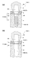
- FIG. 1 It is a figure which shows the dental implant 1 which concerns on 1st embodiment of this invention, Comprising: It is (a) screw type dental implant 1A, (b) cylinder type dental implant 1B. It is the photograph which image
- FIG. 1 It is a figure which shows the artificial hip joint 101 which concerns on 3rd embodiment of this invention. It is the photograph which image
- FIG. 1 is a diagram showing a dental implant 1 according to a first embodiment of the present invention, in which (a) a screw-type dental implant 1A and (b) a cylinder-type dental implant 1B.
- the dental implant 1 is a zirconia implant.
- the dental implant 1 includes a screw-type dental implant 1A and a cylinder-type dental implant 1B.
- the dental implant 1 includes a fixture 10 that is fixed to an alveolar bone (biological tissue, hard tissue) H, and an abutment 20 that is fitted to the fixture 10.
- a crown 6 called an artificial tooth crown is attached to the abutment 20.
- the root end side of the crown 6 is covered with a gum (biological tissue, soft tissue) S.
- the longitudinal direction (direction along the central axis) of the dental implant 1 is referred to as vertical.
- the crown 6 side is referred to as the tip side.
- the tip is also called the first end.
- the fixture 10 side is referred to as the root end side.
- the root end is also called the second end.
- the direction perpendicular to the vertical direction is called horizontal.
- the direction around the central axis of the dental implant 1 is referred to as the circumferential direction.
- the fixture (implant) 10 is a shaft-like member having a center hole (not shown), and is formed of ceramics (biocompatible material, biocompatible ceramic material) containing zirconia.
- the fixture 10 includes a screw-type fixture 10 ⁇ / b> A in which a male screw 15 is formed on the outer surface 11 and a cylinder-type fixture 10 ⁇ / b> B without the male screw 15.
- the screw-type fixture 10A and the cylinder-type fixture 10B differ only in the presence or absence of the male screw 15.
- the screw-type fixture 10 ⁇ / b> A is fixed to the alveolar bone H by screwing into a screw hole formed in the alveolar bone H.
- the cylinder-type fixture 10 ⁇ / b> B is fixed to the alveolar bone H by fitting into a circular hole formed in the alveolar bone H.
- a center hole is opened at the center of the tip surface 13 of the fixture 10.
- the central hole is formed along the vertical direction.
- the shape (length, thickness, etc.) of the fixture 10 is arbitrary. It may be the case where there is no center hole.
- the fixture 10 is formed with a living tissue survival surface 30 (biological tissue survival surfaces 31 to 35).
- the living tissue survival surface 30 is provided on the outer surface 11 of the fixture 10.
- the outer surface 11 includes a tip surface 13, a collar surface 12, and a screw surface (male screw 15).
- the outer surface 11 includes a tip surface 13 and an outer peripheral surface 14.
- the living tissue survival surface 30 is a surface excellent in the binding property to the alveolar bone H and the adhesion property to the gum S.
- the living tissue survival surface 30 has a large number of microvilli 41 described later.
- the microvillous bodies 41 are dense.
- the living tissue survival surface 30 is a fine villi dense surface.
- the living tissue living surface 30 may have one or both of a small groove 43 and a large groove 45 described later.
- the fixture 10 adheres not only to the alveolar bone H but also to the mucosal tissue (soft tissue) around the alveolar bone H.
- the distal end surface 13 is in close contact with the gum S.
- the fixture 10 also has an important adhesion property (affinity) with the soft tissue. If the fixture 10 has low adhesion to the gum S, the gum S is inflamed and the gum S retreats or the alveolar bone H decreases (bone resorption). Therefore, it is necessary to increase adhesion between the fixture 10 and the gum S (adhesion to soft tissue) and prevent (block) bacteria from entering.
- the living tissue survival surface 30 improves the bone bonding and gum adhesion of the fixture 10 by the microvillus 41, the small groove 43, and the large groove 45.
- the living tissue survival surface 30 improves the adhesion of the fixture 10 to the living tissue (bondability to hard tissue, adhesion to soft tissue) and accelerates the healing of the living tissue.
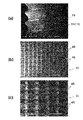
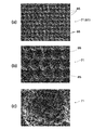
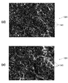
- Bio tissue survival surface 31) 2 and 3 are photographs obtained by photographing the living tissue survival surface 30 (biological tissue survival surface 31) according to the first embodiment of the present invention with an SEM, wherein (a) is a magnification of 30 times, and (b). Is an enlargement ratio of 200 times, (c) is an enlargement ratio of 500 times, (d) is an enlargement ratio of 2000 times, (e) is an enlargement ratio of 5000 times, and (f) is an enlargement ratio of 10,000 times.
- the living tissue living surface 31 is an example of the living tissue living surface 30, and is formed on the outer surface 11 of the fixture 10A.
- the living tissue survival surface 31 has a large number of microvillus bodies 41 whose tips are fingertip-shaped. A large number of microvillus bodies 41 are densely arranged.
- the fingertip shape means a shape having a round tip (hemispherical shape) like a fingertip.
- the microvillous body 41 has a hemispherical protrusion at the tip and is not sharp.
- the microvillous body 41 is formed so that the outer diameter (diameter) of the tip is nanometer size.
- the nanometer size is sometimes referred to as nanometer order, nanometer scale, or nanometer class. In English, it is called “order of magnitude”. In Japanese, it is called “grade”, “class”, “scale” or “digit”.
- the tip diameter of the microvillous body 41 is 1 nm or more and less than 1000 nm.
- the tip diameter of the microvillus 41 is, for example, not less than 50 nm and less than 500 nm. For example, it may be 100 nm or more and less than 300 nm.
- the living tissue survival surface 31 has a three-dimensional surface roughness Sa (arithmetic average height: ISO25178) of nanometer size (1 nm or more and less than 1000 nm).
- the three-dimensional roughness Sa of the living tissue survival surface 31 is, for example, 500 nm or more and 800 nm.
- the living tissue survival surface 31 has an interface development area ratio Sdr (ISO25178) of 0.1 or more and 2.0 or less.
- the living tissue activating surface 31 has an interface development area ratio Sdr of, for example, 0.5 or more and 1.0 or less.
- the living tissue survival surface 31 has a plurality of large grooves 45.
- the plurality of large grooves 45 are arranged to intersect each other.
- a plurality of large grooves 45 are arranged in a lattice pattern. This is to ensure that osteoblasts having an oval shape of about 20 to 30 ⁇ m are firmly established inside the large groove 45.
- the large groove (second groove) 57 has a width of 10 ⁇ m or more and 500 ⁇ m or less.
- the large groove 45 has a width of, for example, 20 ⁇ m or more and 100 ⁇ m or less. It may be 30 ⁇ m or more and 50 ⁇ m or less. This is to prevent preosteoblasts from spreading too much.
- the large groove 45 has a depth of 5 ⁇ m or more and 500 ⁇ m or less. For example, it may be 10 ⁇ m or more and 100 ⁇ m or less. This is to prevent the preosteoblasts from getting over the large groove 45.
- the large grooves 45 arranged in parallel in the vertical direction intersect with the large grooves 45 arranged in parallel in the horizontal direction (circumferential direction).
- the intersecting large grooves 45 may have an intersecting angle of 60 ° or more.
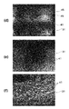
- Bio tissue survival surface 32) 4 and 5 are photographs obtained by photographing the living tissue survival surface 30 (biological tissue survival surface 32) according to the first embodiment of the present invention with an SEM, wherein (a) is an enlargement ratio of 200 times, and (b). Is an enlargement ratio of 500 times, (c) is an enlargement ratio of 2000 times, (d) is an enlargement ratio of 5000 times, (e) is an enlargement ratio of 10,000 times, and (f) is an enlargement ratio of 20000 times.
- the living tissue living surface 32 is an example of the living tissue living surface 30, and is formed on the outer surface 11 of the fixture 10B.
- the living tissue living surface 32 is formed in the same manner as the living tissue living surface 31.
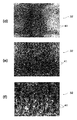
- FIG. 6A and 6B are reference photographs obtained by photographing the surface of the small intestine with an SEM.
- FIG. 6A shows an enlargement ratio of about 100 times
- FIG. 6B shows an enlargement ratio of about 5000 times
- FIG. 6C shows an enlargement ratio of about 10,000 times.
- Villi are fine protrusions protruding from the surface of an organ, and are present in the small intestine and placenta.
- FIGS. 6B and 6C a large number of microvilluss are further concentrated on the surface of the villus.
- the microvillus itself may be called soft hair or soft process.
- the villi and microvilli are protrusions having a fingertip shape at the tip.
- the tip diameter of the microvilli is less than 1 ⁇ m.
- the surface area is remarkably increased by villi and microvilli, and absorption and binding are performed efficiently and effectively.
- the living tissue survival surfaces 31 and 32 have a structure similar to the inner surface of the small intestine or the like.
- the large groove 45 resembles the villi of a living tissue
- the microvilli 41 resembles the villi of a living tissue.
- the living tissue active surface 31 has high connectivity and adhesion with living tissue (hard tissue such as bone, soft tissue such as mucosal tissue).
- the biological tissue activating surface 31 is considered to have a shape close to an ideal as a surface that adheres to and adheres to the biological tissue.
- FIG. 7 is a photograph of the living tissue survival surface 30 (biological tissue survival surface 33) according to the first embodiment of the present invention taken with an SEM, wherein (a) is an enlargement factor of 200 times and (b) is an enlargement factor. 2000 times, (c) is an enlargement rate of 5000 times, and (d) is an enlargement rate of 10,000 times.
- the biological tissue survival surface 33 is an example of the biological tissue survival surface 30 and is formed on the outer surface 11 of the fixture 10B. Similar to the living tissue living surfaces 31 and 32, the living tissue living surface 33 has a large number of microvilli 41. The three-dimensional roughness Sa of the living tissue living surface 33 and the developed area ratio Sdr of the interface are the same as those of the living tissue living surfaces 31 and 32.
- the living tissue survival surface 33 has a plurality of large grooves 45 arranged in parallel. The shape and the like of the large groove 45 are as described above.
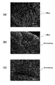
- FIG. 8 is a photograph of the living tissue survival surface 30 (biological tissue survival surface 34) according to the first embodiment of the present invention taken with an SEM, wherein (a) is an enlargement factor of 200 times and (b) is an enlargement factor. 500 times (c) is an enlargement factor of 10,000 times.
- the living tissue living surface 34 is an example of the living tissue living surface 30, and is formed on the outer surface 11 of the fixture 10B.
- the living tissue activating surface 34 has a large number of microvillous bodies 41, like the living tissue activating surfaces 31 to 33.
- the three-dimensional roughness Sa of the living tissue living surface 34 and the developed area ratio Sdr of the interface are the same as those of the living tissue living surfaces 31 to 33.
- the living tissue survival surface 34 includes a plurality of small grooves 43 and large grooves 45.
- the plurality of small grooves 43 are arranged in parallel.
- the plurality of large grooves 45 are also arranged in parallel.
- the small grooves 43 and the large grooves 45 intersect in a lattice pattern.
- the small groove 43 and the large groove 45 may have an intersection angle of 60 ° or more.
- the shape and the like of the large groove 45 are as described above.
- the small grooves (first grooves) 43 have a width of 1 ⁇ m or more and 50 ⁇ m or less, and are arranged in parallel.
- the small groove 43 has a width of, for example, 1 ⁇ m or more and 20 ⁇ m. For example, it may be 5 ⁇ m or more and 10 ⁇ m or less.
- the small groove 43 has a depth of 1 ⁇ m or more and 20 ⁇ m or less. For example, it may be 2 ⁇ m or more and 5 ⁇ m or less. This is to give mechanical stimulation
- FIG. 9 is a photograph of the living tissue survival surface 30 (biological tissue survival surface 35) according to the first embodiment of the present invention taken with an SEM, wherein (a) is an enlargement factor of 500 times and (b) is an enlargement factor. 10,000 times.
- the biological tissue survival surface 35 is an example of the biological tissue survival surface 30, and is formed on the outer surface 11 of the fixture 10A.
- the biological tissue survival surface 35 has a large number of microvilli 41 as in the biological tissue survival surfaces 31 to 34.
- the three-dimensional roughness Sa of the living tissue living surface 35 and the developed area ratio Sdr of the interface are the same as those of the living tissue living surfaces 31 to 34.
- the living tissue survival surface 35 has a plurality of small grooves 43 arranged in parallel and a plurality of large grooves 45 arranged in parallel.
- the small groove 43 and the large groove 45 are arranged in parallel.
- a plurality of small grooves 43 are arranged (overlapped) inside the large groove 45.
- the small groove 43 and the large groove 45 are parallel.
- the small groove 43 and the large groove 45 may have an intersection angle of 30 ° or less.
- the shape and the like of the small groove 43 and the large groove 45 are as described above.
- FIG. 19 is a reference photograph in which the outer surface of a conventional titanium fixture is taken with an SEM (magnification rate 2000 times), where (a) is a product of Company A, (b) is a product of Company B, and (c) is Company C product, (d) is Company D product.
- the outer surface is roughened (porous). These outer surfaces are roughened by edging or blasting with hydrochloric acid or the like. These outer surfaces have a large number of pores, and further have a large number of protrusions with sharp tips around the pores.
- the outer surface of the conventional fixture has a three-dimensional roughness Sa of 2 ⁇ m or more. However, any of the outer surfaces of the conventional fixture does not have a hemispherical (finger-tip-shaped) protrusion (microvillus) and cannot be said to be a microvilli dense surface.
- the abutment (implant) 20 is a shaft-like member and is formed of ceramics containing zirconia.
- the abutment 20 has a main body portion 23 and a tapered shaft portion 25.
- the taper shaft portion 25 is fitted into the center hole of the fixture 10, and the main body portion 23 is disposed so as to be exposed from the front end side of the fixture 10.
- the main body portion 23 is formed in a truncated cone shape or the like, and the crown 6 is attached using an adhesive, cement, or the like.
- the root end side region not covered by the crown 6) than the crown 6 is referred to as a gingival margin 24 (gingival margin).
- the gingival margin 24 is exposed between the fixture 10 and the crown 6.
- the abutment 20 is formed with a living tissue survival surface 30 (biological tissue survival surfaces 31 to 35).
- the biological tissue survival surface 30 is provided on the outer surface 21 of the abutment 20.
- the living tissue survival surface 30 is provided on the gingival margin surface (gingival margin 24).
- the gingival margin 24 is in close contact with the gum S in the same manner as the distal end surface 13 of the fixture 10. For this reason, the gum S is easily adhered by providing the living tissue survival surface 30 (biological tissue survival surfaces 31 to 35) in the gingival margin 24. Thereby, the fusion of the abutment 20 and the gum S is strengthened as compared with the conventional case.
- the fixture 10 (10A, 10B) has a living tissue active surface 30 (biological tissue active surfaces 31 to 35) on the outer surface 11. Thereby, the fixation (adhesion) to the outer surface 11 of an anterior osteoblast or an osteoblast can be accelerated
- the biological tissue survival surface 30 (biological tissue survival surfaces 31 to 35) has a large number of small grooves 43 and large grooves 45. This can promote the proliferation of preosteoblasts. Since various modes (number, shape, arrangement) of the small grooves 43 and the large grooves 45 can be set, a mechanical stimulus (mechanical stress) can be effectively applied to the preosteoblasts. Therefore, differentiation into osteoblasts is promoted, and the bone bonding period is shortened.
- the living tissue survival surface 30 includes a plurality of ups and downs having different scale sizes.
- the microvillous body 41 forms nanometer-sized irregularities.
- the small groove 43 forms a single-micron size unevenness.
- the large groove 45 forms irregularities having a larger scale size than these. Therefore, the living tissue survival surface 30 can efficiently and effectively give mechanical stimulation to the preosteoblasts. Therefore, the bond between the fixture 10 and the alveolar bone H becomes stronger than before, and the bone bond period is also shortened.
- the fixture 10 ⁇ / b> B can bind well to the alveolar bone H because the living tissue survival surface 30 exhibits high bone-binding properties.
- the abutment 20 has a living tissue attachment surface 30 (biological tissue attachment surfaces 31 to 35) on the outer surface 21 (gingival margin 24). Since the living tissue survival surface 30 has a large number of microvillous bodies 41, adhesion to the gums (adhesion to soft tissues) is enhanced and bacteria can be prevented from entering (sealing).
- the dental implant 1 (10A, 10B) is provided with the living tissue attachment surface 30 on the outer surface 11 of the fixture 10 and the outer surface 21 of the abutment 20, respectively, the bonding to the human body becomes stronger.
- the dental implant 1A and the dental implant 1B exhibit the same function and effect.
- the living tissue living surface 30 is provided in a region of the outer surfaces 11 and 21 that is in close contact with (being attached to) the living tissue. As long as the region is in close contact with the living tissue, there may be one place or a plurality of places.
- the area of the living tissue survival surface 30 is arbitrary.
- the living tissue living surface 30 may be provided on almost the entire outer surfaces 11 and 21.
- the living tissue survival surface 30 may be provided over the entire surface of the outer surface 11 that is in close contact with the alveolar bone H (collar surface 12, outer peripheral surface 14, male screw 15).
- the living tissue survival surface 30 may be provided over the entire surface of the outer surface 11 that is in close contact with the gum S (tip surface 13).
- the living tissue survival surface 30 may be provided only on the outer surface 11 or only on the outer surface 21.
- the living tissue activation surface 30 may have different surface properties (surface roughness). This is because the alveolar bone H is coupled to the collar surface 12 and the male screw 15 and the gum S is adhered to the distal end surface 13.
- the living tissue living surface 30 of the gingival margin 24 may be formed to have the same surface properties (surface roughness) as the living tissue living surface 30 of the distal end surface 13. In either case, the gums S are adhered.
- the small groove 43 and the large groove 45 are formed in a semicircular arc shape in cross section.
- the cross-sectional shape may be, for example, a triangle (isosceles triangle) or a rectangle.
- the small groove 43 and the large groove 45 may have a uniform width or a different width in the extending direction.
- the depth may be uniform over the extending direction or different depths.
- the plurality of small grooves 43 and the plurality of large grooves 45 may have uniform widths or different widths.
- the depth may be uniform or different.
- the number of the small grooves 43 and the large grooves 45 is arbitrary.
- the small groove 43 and the large groove 45 are not limited to a straight line and may be curved. It is preferable that the adjacent small grooves 43 and the large grooves 45 are arranged with no gap as much as possible.
- the extending direction of the small groove 43 and the large groove 45 is an arbitrary angle with respect to the vertical direction of the fixture 10.
- the biological tissue survival surface 30 may be mixed on the outer surfaces 11 and 21. Any one or more of the living tissue survival surfaces 31 to 35 may be provided.
- the number, shape, and arrangement of the small grooves 43 and the large grooves 45 can be arbitrarily set on the living tissue survival surface 30.
- the small groove 43 and the large groove 45 may have a form other than that in the living tissue living surface 31 to 35.
- a plurality of large grooves 45 may be arranged in a lattice shape, and a plurality of small grooves 43 may be arranged in a lattice shape (the large grooves 45 and the small grooves 43 intersect and overlap).
- a plurality of large grooves 45 may be arranged in parallel, and a plurality of small grooves 43 may be arranged in a lattice shape (the large grooves 45 and the small grooves 43 intersect and overlap).
- the living tissue survival surface 30 may have only a large number of microvilli 41 and may not have the small grooves 43 and the large grooves 45 (see the biological tissue survival surface 131 of the third embodiment).
- the dental implant 1 (1A, 1B) is formed from a biocompatible ceramic material.
- the fixture 10 (10A, 10B) and the abutment 20 are formed from a ceramic material containing zirconium oxide.
- the manufacturing process of the fixture 10 (10A, 10B) includes a molding process, a sintering process, and a surface processing process.
- the surface processing step is a process for forming a living tissue active surface and includes a laser non-thermal processing step. Since the manufacturing process of the abutment 20 is the same as the manufacturing process of the fixture 10, the description thereof is omitted.
- the outer surface 11 of the zirconia sintered body is irradiated with laser light to form the living tissue active surface 30 (the biological tissue active surfaces 31 to 35) on the outer surface 11.
- a laser beam of an ultrashort pulse laser is used.
- a laser beam of a picosecond laser or a femtosecond laser can be used.
- the ultrashort pulse laser is a laser with a very short pulse having a pulse width (time width) of several picoseconds to several femtoseconds.
- the several picosecond laser is a laser having a pulse width of 1 trillionth of a second.
- the femtosecond laser is a laser having a pulse width of 1/1000 trillion seconds.
- Non-thermal processing is processing in which laser light is irradiated under atmospheric pressure (in air containing moisture) to instantaneously melt, evaporate, and scatter. Since the melted portion is instantly evaporated and scattered and removed, there is very little thermal influence (thermal damage) around the processed part.
- a pulse laser having a large laser beam output peak power or energy density
- a living tissue living surface 30 having a large number of microvilli 41 is formed.
- the number or shape (size) of the microvilli 41 can be changed.
- the small grooves 43 and the large grooves 45 are dug into the outer surface 11 by scanning while irradiating laser light.
- a plurality of small grooves 43 and large grooves 45 are formed by scanning the laser light a plurality of times.
- the processing width (light diameter) by the laser beam can be changed.
- the width and depth of the small groove 43 and the large groove 45 can be changed by adjusting the output (processing width) of the laser beam.
- the widths and depths of the small grooves 43 and the large grooves 45 can be changed according to the number of times of irradiation, the scanning speed, the laser light output, and the like for the same location.
- the large groove 45 is formed first, and then the small groove 43 is formed.
- the small grooves 43, the large grooves 45, or the small grooves 43 and the large grooves 45 are arranged in a lattice shape, scanning is performed in two directions that intersect (directly) the laser beams.
- the crossing angle of scanning at this time is the crossing angle between the small grooves 43, the large grooves 45, or the small grooves 43 and the large grooves 45.
- the outer surface 11 When the outer surface 11 is shaved with laser light to form the large grooves 45 and the small grooves 43, a large number of microvillus bodies 41 are simultaneously formed on the inner surfaces of the large grooves 45 and the small grooves 43.
- the microvillous body 41, the small groove 43, and the large groove 45 are formed at the same time, and become the living tissue active surface 30 (the biological tissue active surfaces 31 to 35).
- laser non-thermal processing of the collar surface 12, the tip surface 13, and the male screw 15 may be performed with different laser beam outputs.
- the surface properties (surface roughness) of the living tissue tissue attachment surface 30 in the collar surface 12, the tip surface 13, and the male screw 15 are varied. This is because the alveolar bone H is coupled to the collar surface 12 and the male screw 15 and the gum S is adhered to the distal end surface 13.
- the fixture 10 After forming the living tissue survival surface 30 (biological tissue survival surfaces 31 to 35), washing and sterilization are performed. In this way, the fixture 10 is manufactured.
- the present invention is not limited to the case where the surface processing step (formation of the living tissue active surface) is performed after the fixture 10 is subjected to the main sintering process.
- a surface processing step may be performed on the zirconia sintered body, followed by a main sintering process.
- the zirconia sintered body contracts, and the microvillus 41, the small groove 43, and the large groove 45 are also reduced. Therefore, the living body tissue attachment surface 30 is formed to be large in consideration of the shrinkage of the zirconia sintered body.
- the fixture 10 biological tissue activating surface 30 of the same shape as the case where it forms after this sintering process is obtained.
- the small groove 43 and the large groove 45 are not limited to being formed by laser non-thermal processing.
- the small groove 43 and the large groove 45 may be molded on the outer surface 11.
- the outer surface 11 Prior to laser non-thermal processing, the outer surface 11 may be laser-heat processed to form the small grooves 43 and the large grooves 45.
- the living tissue active surface 30 (the biological tissue active surfaces 31 to 35) can be formed on the fixture 10 made of zirconium or the like.
- FIG. 10 is a diagram showing a dental implant 3 according to a second embodiment of the present invention, in which (a) a screw-type dental implant 3A and (b) a cylinder-type dental implant 3B.
- the members having the same shape as those in the first embodiment are denoted by the same reference numerals, and the description thereof is omitted.
- the dental implant 3 is a metal (titanium alloy) implant.
- the dental implant 3 includes a screw type dental implant 3A and a cylinder type dental implant 3B.
- the dental implant 3 includes a fixture 50 that is fixed to the alveolar bone H, and an abutment 60 that is fitted to the fixture 50.
- the fixture (implant) 50 is a shaft-like member having a central hole (not shown), and is formed of a titanium alloy (biocompatible material, biocompatible metal material).
- the fixture 50 differs from the fixture 10 only in material.
- the fixture 50 includes a screw type fixture 50 ⁇ / b> A in which a male screw 15 is formed on the outer surface 51 and a cylinder type fixture 50 ⁇ / b> B without the male screw 15.
- the screw-type fixture 50A and the cylinder-type fixture 50B differ only in the presence or absence of the male screw 15.
- the fixture 50 is formed with a living tissue survival surface 70 (a biological tissue survival surface 71).
- the living tissue survival surface 70 is provided on the outer surface 51 of the fixture 50.
- the outer surface 51 includes a tip surface 13, a collar surface 12, and a screw surface (male screw 15).
- the outer surface 51 includes the tip surface 13 and the outer peripheral surface 14.
- the living tissue survival surface 70 is a surface that is excellent in the binding property to the alveolar bone H and the adhesion property to the gum S.
- the living tissue survival surface 70 has a large number of microvilli 81 described later.
- the microvillus 81 is dense. Similar to the biological tissue survival surface 30, the biological tissue survival surface 70 is a fine villi dense surface.
- the living tissue survival surface 70 may have one or both of a small groove 83 and a large groove 85 described later.
- the living tissue living surface 70 is different from the living tissue living surface 30 only in material.
- the microvillus 81 corresponds to the microvilli 41
- the small groove 83 corresponds to the small groove 43
- the large groove 85 corresponds to the large groove 45.
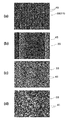
- FIG. 11 and FIG. 12 are photographs taken by SEM of the living tissue survival surface 70 (biological tissue survival surface 71) according to the second embodiment of the present invention, where (a) is an enlargement ratio of 200 times, and (b). Is an enlargement ratio of 500 times, (c) is an enlargement ratio of 2000 times, (d) is an enlargement ratio of 5000 times, and (e) is an enlargement ratio of 10,000 times.
- the biological tissue survival surface 71 is an example of the biological tissue survival surface 70 and has a large number of microvilli 81.
- the shape and the like of the microvilli 81 are the same as those of the microvilli 41.
- the three-dimensional surface roughness Sa of the living tissue living surface 71 and the developed area ratio Sdr of the interface are the same as those of the living tissue living surface 30.
- the living tissue survival surface 71 has a plurality of large grooves 85 arranged in an intersecting manner. A plurality of large grooves 85 are arranged in a lattice pattern. The number and shape of the large grooves 85 are the same as those of the large grooves 45.
- the biological tissue survival surface 71 has the same form as the biological tissue survival surface 31.
- the living tissue living surface 70 a surface having the same form as the living tissue living surfaces 32 to 35 may be formed.
- the number and shape of the small grooves 83 are the same as those of the small grooves 43.
- the living tissue living surface 70 may include only a large number of microvillus bodies 81 and may not include the small grooves 83 and the large grooves 85 (see the living tissue living surface 131 of the third embodiment).
- the abutment (implant) 80 is made of a titanium alloy.
- the abutment 60 is formed with a living tissue survival surface 70 (a biological tissue survival surface 71).
- the living tissue survival surface 70 is provided on the outer surface 61 of the abutment 60.
- the living tissue survival surface 70 is provided on the gingival margin surface (gingival margin 24).
- the abutment 60 is different from the abutment 20 only in material.
- the fixture 50 (50A, 50B) and the abutment 60 have the same functions and effects as the fixture 10 (10A, 10B) and the abutment 20.
- the biological tissue survival surface 70 has the same effects as the biological tissue survival surface 30.
- the living tissue survival surface 70 improves the adhesion to the living tissue (bondability to hard tissue, adhesion to soft tissue) and accelerates the healing of the living tissue. Therefore, the dental implant 3 (3A, 3B) exhibits the same function and effect as the dental implant 1 (1A, 1B).
- the dental implant 3 (3A, 3B) is formed from a biocompatible metal material.
- Fixture 50 (50A, 50B) and abutment 60 are formed from a titanium alloy material.
- the manufacturing process of the fixture 50 includes a machining process and a surface processing process.
- the surface processing step is a process for forming a living tissue active surface, and includes an acid etching step and a laser non-thermal processing step. Since the manufacturing process of the abutment 60 is the same as the manufacturing process of the fixture 50, description thereof is omitted.
- the titanium alloy material is cut with a composite lathe or the like, or plastically processed to form a titanium workpiece (metal workpiece). Blasting is performed on the outer surface 51 of the titanium workpiece. This is to increase the efficiency of acid etching in the subsequent process.
- the blasting process for the titanium workpiece is optional. After machining, the titanium workpiece is washed with water or alcohol.
- the surface processing step first, the outer surface 51 of the titanium processed body is subjected to acid etching.
- the titanium processed body is dipped in hydrochloric acid for edging.
- the concentration of hydrochloric acid is, for example, 1 to 20%
- the liquid temperature is, for example, 30 ° C. to 80 ° C.
- the immersion time is, for example, 10 minutes to 60 minutes.
- the acid used for edging may be other than hydrochloric acid. Sulfuric acid, hydrofluoric acid, nitric acid, and the like, and mixed acids thereof can be used.
- the titanium processed body is ultrasonically cleaned with pure water.
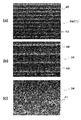
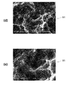
- FIGS. 13 and 14 are photographs obtained by photographing the outer surface 51 of the acid-etched titanium processed body with an SEM.
- FIG. 13A is an enlargement factor of 200 times
- FIG. 13B is an enlargement factor of 500 times
- FIG. The enlargement rate is 2000 times
- (d) is the enlargement rate 5000 times
- (e) is the enlargement rate 10000 times.
- FIGS. 13 and 14 are photographs obtained by photographing the outer surface 51 of the acid-etched titanium processed body with an SEM.
- FIG. 13A is an enlargement factor of 200 times
- FIG. 13B is an enlargement factor of 500 times
- the enlargement ratio 2000 is the enlargement ratio 5000 times
- (e) is the enlargement ratio 10,000 times.
- the outer surface 51 of the acid-etched titanium processed body (acid-etched metal body) has a large number of pores, and further has a number of protrusions with sharp tips around the pores.
- the outer surface 51 is a rough surface (porous), and the conventional fixture is the same as the outer surface (see FIG. 19).
- the microvilli 41 is not yet present on the outer surface 51.
- the outer surface 51 of the titanium processed body is irradiated with laser light to form a living tissue activating surface 70 (biological tissue activating surface 71) on the outer surface 51.
- This laser non-thermal processing step is the same as the laser non-thermal processing step of the living tissue living surface 30.
- the outer surface 51 of the acid-etched titanium workpiece is irradiated with a laser beam such as a femtosecond laser, the outer surface 51 is non-thermally processed (laser non-thermal processing).
- laser non-thermal processing When the outer surface 51 is non-thermally processed with laser light, a large number of microvillus bodies 81 are formed.
- the small groove 83 and the large groove 85 are dug into the outer surface 51 by scanning while irradiating laser light.
- the microvillus body 81, the small groove 83, and the large groove 85 are simultaneously formed to become the living tissue active surface 70 (the biological tissue active surface 71).
- the fixture 50 is manufactured.
- the small groove 83 and the large groove 85 are not limited to being formed by laser non-thermal processing.
- a small groove 83 and a large groove 85 may be formed on the outer surface 51.
- the outer surface 51 Prior to laser non-thermal processing, the outer surface 51 may be laser-heated to form the small groove 83 and the large groove 85.
- the living tissue survival surface 70 (biological tissue survival surface 71) can be formed on the titanium alloy fixture 50 and the like.
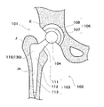
- FIG. 15 is a view showing an artificial hip joint 101 according to the third embodiment of the present invention.
- the artificial hip joint 101 is replaced with a hip joint in order to restore its function when the hip joint is damaged.
- the hip prosthesis 101 is composed of a femoral component 102 embedded in the femur J and an acetabular component 106 embedded in the acetabulum K.
- the femoral component 102 includes a stem 103 and a head 104.
- the stem 103 is embedded in a femur (biological tissue, hard tissue) J and supports the head 104.
- the head 104 is a spherical member that serves as the head of the femur J, and is formed of a biocompatible ceramic material such as zirconia.
- the acetabular component 106 includes a cup 107 and a liner 108.
- the cup 107 is a hook-shaped member embedded in the acetabulum (biological tissue, hard tissue) K, and is formed of a biocompatible ceramic material such as zirconia or a biocompatible metal material such as titanium alloy.
- the living tissue living surface 30, 70 may be formed on the outer surface of the cup 107.
- the liner 108 is a bowl-shaped member fixed to the inside of the cup 107, and is formed of, for example, an ultra high molecular polyethylene resin.
- the liner 108 slidably supports the head 104 and serves as an articulating surface.
- the direction in which the femoral component 102 extends is referred to as the longitudinal direction.
- the head 104 side is referred to as the tip (first end), and the stem 103 side is referred to as the end (second end).
- the width direction of the stem 103 is referred to as a lateral direction.
- the thickness direction of the stem 103 is referred to as the front-rear direction.
- the stem (implant) 103 is inserted into a stricture Ja formed in the femur J to be bone-bonded.
- the stem 103 supports the head 104 and transmits a load to the femur J.
- the stem 103 is formed of a biocompatible resin material (biocompatible material).
- the stem 103 is made of a polyether ether ketone resin (PEKK).
- the stem 103 has a body part 111, a leg part 112, and a neck part 113, which are integrally formed of polyetheretherketone resin.
- the body part 111 is a block-like part extending in the longitudinal direction, and is inserted into the stricture Ja to be bone-bonded.
- the body portion 111 has a vertical length of about 50 mm.
- the width of the body part 111 gradually decreases from the front end side toward the end side.
- the tip side is about 33 mm and the end side is about 15 mm.
- the thickness of the body part 111 is substantially constant from the distal end side toward the distal end side.
- the tip side is about 13 mm and the end side is about 11 mm.
- the leg portion 112 is a substantially quadrangular prism-shaped portion extending in the vertical direction, and is disposed on the terminal side of the body portion 111.
- the leg portion 112 guides the insertion of the body portion 111 into the constriction hole Ja, and maintains the posture after the stem 103 is embedded.
- the leg portion 112 has a vertical length of about 90 mm.
- the leg part 112 becomes gradually thinner from the tip toward the end.
- the neck portion 113 is a substantially cylindrical portion extending in the vertical direction, and is disposed on the distal end side of the body portion 111.
- the neck portion 113 projects from the stricture Ja to introduce a load from the acetabulum side.
- the neck 113 has a length of about 22 mm.
- the neck portion 113 gradually becomes thicker from the tip toward the end.
- a head coupling portion is formed at the tip of the neck portion 113.
- the stem 103 is formed with a living tissue survival surface 130 (a biological tissue survival surface 131).
- the living tissue survival surface 130 is provided on the outer surface 115 of the portion (body portion 111, leg portion 112) to be embedded in the stricture Ja among the outer surface of the stem 103.
- the biological tissue survival surface 130 is also provided at least on the outer surface 115 of the body portion 111.
- the biological tissue survival surface 130 is a surface excellent in the binding property to the natural bone (femur J) similarly to the biological tissue survival surfaces 30 and 70.
- the living tissue survival surface 130 has a large number of microvilli 141 described later.
- the microvillus 141 is dense.
- the biological tissue survival surface 130 is a microvillus dense surface, like the biological tissue survival surfaces 30 and 70.
- the living tissue survival surface 130 includes the microvillus 141, and may further include one or both of a small groove and a large groove.
- the living tissue living surface 130 is different from the living tissue living surfaces 30, 70 only in material.
- the microvilli 141 corresponds to the microvilli 41, 81
- the small grooves correspond to the small grooves 43, 83
- the large grooves correspond to the large grooves 45, 85.
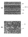
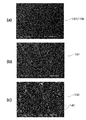
- FIGS. 16 and 17 are photographs taken by SEM of the living tissue survival surface 130 (biological tissue survival surface 131) according to the third embodiment of the present invention, where (a) is an enlargement ratio of 200 times, and (b). Is an enlargement ratio of 500 times, (c) is an enlargement ratio of 2000 times, (d) is an enlargement ratio of 5000 times, and (e) is an enlargement ratio of 10,000 times.
- the biological tissue survival surface 131 is an example of the biological tissue survival surface 130 and has a large number of microvilli 141.
- the shape and the like of the microvilli 141 are the same as those of the microvilli 41 and 81.
- the three-dimensional surface roughness Sa of the living tissue living surface 131 and the developed area ratio Sdr of the interface are the same as those of the living tissue living surfaces 30 and 70.
- the living tissue living surface 130 a surface having the same form as the living tissue living surfaces 31 to 35, 71 and the like may be formed.
- the biological tissue survival surface 130 may have a small groove or a large groove.
- the small grooves and the large grooves correspond to the small grooves 43 and 83 and the large grooves 45 and 85, respectively.
- the number and shape of the small grooves and large grooves on the living tissue active surface 130 are the same as those of the small grooves 43 and 83 and the large grooves 45 and 85.
- the stem 103 has the same effect as the fixtures 10 and 50.
- the biological tissue survival surface 130 has the same effects as the biological tissue survival surfaces 30 and 70.
- the living tissue adhesion surface 130 improves the adhesion to the living tissue (bonding property to the hard tissue) and accelerates the healing of the living tissue.
- the living tissue survival surface 130 can exhibit the ability to adhere to the living tissue only on the resin surface. For this reason, it is not necessary to coat the resin surface with metal or ceramics, or to mix metal or ceramics into the resin material. Since the artificial hip joint 101 is provided with the living tissue survival surface 130 on the outer surface 115 of the stem 103, the connection to the human body becomes stronger. Therefore, the artificial hip joint 101 exhibits the same function and effect as the dental implants 1 and 3.
- the artificial hip joint 101 is formed from a biocompatible resin material.
- the stem 103 is formed from a polyetheretherketone resin.
- the manufacturing process of the stem 103 includes a molding process and a surface processing process.
- the surface processing step is a process for forming a living tissue active surface and includes a laser non-thermal processing step. Since the manufacturing process of the head 104, the cup 107, and the liner 108 is the same as the conventional process, the description thereof is omitted.
- the outer surface 115 of the polyether ether ketone molded body is irradiated with laser light to form a living tissue active surface 130 (biological tissue active surface 131) on the outer surface 115.
- This laser non-thermal processing step is the same as the laser non-thermal processing step of the living tissue living surface 30,70.
- the outer surface 115 of the polyether ether ketone molded body is irradiated with a laser beam such as a femtosecond laser, the outer surface 115 is subjected to non-thermal processing (laser non-thermal processing).
- laser non-thermal processing When the outer surface 115 is non-thermally processed with a laser beam, a living tissue survival surface 131 having a large number of microvilli 141 is formed.
- a small groove or a large groove may be dug into the outer surface 115 by scanning while irradiating with laser light.
- the microvillus 141, the small groove, and the large groove are simultaneously formed to become the living tissue living surface 130.
- the stem 103 is manufactured.
- the small groove 83 and the large groove 85 are not limited to being formed by laser non-thermal processing.
- a small groove 83 and a large groove 85 may be formed on the outer surface 51.
- the outer surface 51 Prior to laser non-thermal processing, the outer surface 51 may be laser-heated to form the small groove 83 and the large groove 85.
- the living tissue survival surface 130 is provided in a region (outer surface 115) of the outer surface of the stem 103 that is in close contact with (is attached to) the femur J. As long as the surface is in close contact with the femur J, there may be one place or a plurality of places.
- the area of the living tissue survival surface 130 is arbitrary.
- the living tissue living surface 130 may be provided on almost the entire outer surface 115.
- the living tissue survival surface 130 may be provided only on the outer surface of the body portion 111 (the surface excluding the outer surface of the leg portion 112) of the outer surface 115.
- the living tissue survival surface 130 (biological tissue survival surface 131) can be formed on the stem 103 made of polyetheretherketone resin.
- the stem 103 is not limited to the polyether ether ketone resin, but may be formed of a biocompatible ceramic material such as zirconia or a biocompatible metal material such as a titanium alloy.
- the living tissue living surface 30, 70 may be formed on the outer surface 115 of the stem 103.
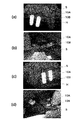
- FIG. 18A and 18B are photographs showing the results of animal experiments, where FIG. 18A is an X-ray photograph of the left mandibular alveolar bone H, FIG. 18B is a photograph of the right mandibular gum S, and FIG. 18C is the left mandibular alveolar bone.
- An X-ray photograph of H, (d) is a photograph of the gum S of the right lower jaw.
- One fixture 10A and one fixture 10B were embedded in the alveolar bone H of the left and right lower jaws of the dog. Four weeks after the implantation, the state of the fixture 10 was photographed with an X-ray or the like.
- Fixation 10 (10A, 10B) and gum S had high adhesion (adhesion to soft tissue), and could prevent (block) bacterial invasion.
- the fixtures (10A, 10B) were bone-bonded so that they could not be extracted from the alveolar bone H by human power.
- the fixtures (10A, 10B) and the alveolar bone H had high bone bonding (bondability to hard tissue), and the bone bonding period could be shortened.
- the fixture 10 (10A, 10B) has improved adhesiveness (bonding property to hard tissue and adhesion property to soft tissue), and has been able to enhance (accelerate) the healing of living tissue.
- the present invention is not limited to the above-described embodiment, and includes various modifications made to the above-described embodiment without departing from the spirit of the present invention. That is, the specific shapes, configurations, and the like given in the embodiment are merely examples, and can be changed as appropriate.
- the implant of the present invention may be an artificial bone, a bone grafting material, or the like. Artificial bones and bone prosthetic materials are used to supplement bone-deleted parts caused by fractures or tumor resections or cartilage removed by lumbar spine surgery.
- the implant of the present invention may be an artificial joint member, an osteosynthesis material used for fixing a fracture site, or a fixing device such as a spine (a spinal implant or a lumbar implant).
- the implant is not limited to being implanted in the living body (inside the body), and may be fixed to the body surface. Implants may be applied not only to humans but also to pets and livestock.
- the living tissue survival surface may have irregularities such as other grooves and wrinkles in addition to or instead of the small grooves and large grooves.
- zirconia zirconium oxide
- a combination of zirconia and carbon, resin, glass, or the like may be used.
- Zirconia (zirconium oxide) may be contained by 50% or more in the volume ratio of the implant.
- Zirconia (zirconium oxide) is contained 90% or more in the volume ratio of the implant.
- alumina aluminum oxide
- yttrium oxide hafnium oxide
- silicone oxide magnesium oxide
- cerium oxide cerium oxide
- the biocompatible metal material may be copper, titanium, titanium alloy, cobalt chromium alloy, or the like.
- the biocompatible resin material may be silicon, nylon, POM, composite material, or the like.
Abstract
Description
歯科用インプラントは、生体適合性金属材料や生体適合性セラミックス材料等の生体適合性材料により形成される。生体適合性金属材料は、チタンやチタン合金、コバルトクロム合金等である。生体適合性セラミックス材料は、アルミナやジルコニア等である。
人工股関節や人工骨等は、生体適合性金属材料や生体適合性セラミックス材料の他、生体適合性樹脂材料により形成される。
樹脂製のインプラントでは、例えば樹脂表面を金属やセラミックスでコーティングし、このコーティングを粗面化したものがある。
図1は、本発明の第一実施形態に係る歯科用インプラント1を示す図であって、(a)スクリュー型の歯科用インプラント1A、(b)シリンダ型の歯科用インプラント1Bである。
歯科用インプラント1は、歯槽骨(生体組織、硬組織)Hに固定されるフィクスチャー10と、フィクスチャー10に嵌合するアバットメント20と、を備える。
アバットメント20には、人工歯冠と呼ばれるクラウン6が装着される。クラウン6よりも根端側は、歯茎(生体組織、軟部組織)Sに覆われる。
縦方向に直行する方向を横と言う。歯科用インプラント1の中心軸周りの方向を周方向と言う。
フィクスチャー10には、外表面11に雄ネジ15が形成されたスクリュー型のフィクスチャー10Aと、雄ネジ15のないシリンダ型のフィクスチャー10Bがある。スクリュー型のフィクスチャー10Aとシリンダ型のフィクスチャー10Bは、雄ネジ15の有無のみが異なる。
シリンダ型のフィクスチャー10Bは、歯槽骨Hに形成した円形穴に嵌合することにより、歯槽骨Hに固定される。
フィクスチャー10の形状(長さ、太さ等)は、任意である。中心穴が存在しない場合であってもよい。
フィクスチャー10には、生体組織活着面30(生体組織活着面31~35)が形成される。生体組織活着面30は、フィクスチャー10の外表面11に設けられる。
フィクスチャー10Aでは、外表面11は、先端面13、カラー面12、ネジ面(雄ネジ15)を含む。
フィクスチャー10Bでは、外表面11は、先端面13と外周面14を含む。
生体組織活着面30は、微絨毛体41に加えて、後述する小溝43、大溝45をのいずれか一方もしくは両方を有してもよい。
生体組織活着面30は、微絨毛体41、小溝43、大溝45により、フィクスチャー10の骨結合、歯茎癒着を向上させる。生体組織活着面30は、生体組織に対するフィクスチャー10の活着性(硬組織への結合性、軟部組織への癒着性)を向上させて、生体組織の癒合を早める。
図2および図3は、本発明の第一実施形態に係る生体組織活着面30(生体組織活着面31)をSEMで撮影した写真であって、(a)は拡大率30倍、(b)は拡大率200倍、(c)は拡大率500倍、(d)は拡大率2000倍、(e)は拡大率5000倍、(f)は拡大率10000倍である。
生体組織活着面31は、先端が指頭形状の微絨毛体41を多数有する。多数の微絨毛体41が密集配置される。指頭形状とは、指先の様に、先端が丸い形状(半球形状)を意味する。微絨毛体41は、先端が半球形状の突起であり、尖っていない。
微絨毛体41の先端径は、1nm以上、1000nm未満である。微絨毛体41の先端径は、例えば50nm以上、500nm未満である。例えば100nm以上、300nm未満でもよい。
大溝(第二溝)57は、幅が10μm以上、500μm以下である。大溝45は、幅が例えば20μm以上、100μm以下である。30μm以上、50μm以下でもよい。前骨芽細胞が広がり過ぎないようにするためである。
大溝45は、深さが5μm以上、500μm以下である。例えば10μm以上、100μm以下でもよい。前骨芽細胞が大溝45を乗り越えないようにするためである。
縦方向に並列する大溝45と横方向(周方向)に並列する大溝45が交差する。交差する大溝45同士は、交差角度が60°以上であればよい。
図4および図5は、本発明の第一実施形態に係る生体組織活着面30(生体組織活着面32)をSEMで撮影した写真であって、(a)は拡大率200倍、(b)は拡大率500倍、(c)は拡大率2000倍、(d)は拡大率5000倍、(e)は拡大率10000倍、(f)は拡大率20000倍である。
生体組織活着面32は、生体組織活着面31と同一に形成される。
図6は、小腸の表面をSEMで撮影した参考写真であって、(a)は拡大率約100倍、(b)は拡大率約5000倍、(c)は拡大率約10000倍である。
図6(b),(c)に示すように、絨毛の表面には、さらに多数の微絨毛(microvillus)が密集する。微絨毛自体を柔毛、柔突起(じゅうとっき)と呼ぶ場合もある。
絨毛および微絨毛は、先端が指頭形状の突起である。微絨毛の先端径は、1μm未満である。小腸や胎盤などは、絨毛、微絨毛によって表面積が著しく増大し、吸収や結合などが効率的、効果的に行われている。
このため、生体組織活着面31は、生体組織(骨等の硬組織、粘膜組織等の軟部組織)との結合性や癒着性が高い。生体組織活着面31は、生体組織に密着して活着する表面として、理想に近い形状と考えられる。
図7は、本発明の第一実施形態に係る生体組織活着面30(生体組織活着面33)をSEMで撮影した写真であって、(a)は拡大率200倍、(b)は拡大率2000倍、(c)は拡大率5000倍、(d)は拡大率10000倍である。
生体組織活着面33は、生体組織活着面31,32と同様に、微絨毛体41を多数有する。生体組織活着面33の三次元粗さSaと界面の展開面積比Sdrは、生体組織活着面31,32と同一である。
生体組織活着面33は、並列配置された複数の大溝45を有する。大溝45の形状等は、上述の通りである。
図8は、本発明の第一実施形態に係る生体組織活着面30(生体組織活着面34)をSEMで撮影した写真であって、(a)は拡大率200倍、(b)は拡大率500倍(c)は拡大率10000倍である。
生体組織活着面34は、生体組織活着面31~33と同様に、微絨毛体41を多数有する。生体組織活着面34の三次元粗さSaと界面の展開面積比Sdrは、生体組織活着面31~33と同一である。
複数の小溝43は、並列配置される。複数の大溝45も、並列配置される。小溝43と大溝45が格子状に交差する。小溝43と大溝45は、交差角度が60°以上であればよい。
大溝45の形状等は、上述の通りである。
小溝(第一溝)43は、幅が1μm以上、50μm以下であり、並列に配置される。小溝43は、幅が例えば1μm以上、20μmである。例えば5μm以上、10μm以下でもよい。小溝43は、深さが1μm以上、20μm以下である。例えば2μm以上、5μm以下でもよい。骨芽細胞に対して力学的な刺激(メカニカルストレス)を与えためである。
図9は、本発明の第一実施形態に係る生体組織活着面30(生体組織活着面35)をSEMで撮影した写真であって、(a)は拡大率500倍、(b)は拡大率10000倍である。
生体組織活着面35は、生体組織活着面31~34と同様に、微絨毛体41を多数有する。生体組織活着面35の三次元粗さSaと界面の展開面積比Sdrは、生体組織活着面31~34と同一である。
生体組織活着面35は、並列配置された複数の小溝43と、並列配置された複数の大溝45を有する。小溝43と大溝45が並列配置される。大溝45の内側に、複数の小溝43が配置(重畳)される。小溝43と大溝45は平行である。小溝43と大溝45は、交差角度が30°以下であればよい。
小溝43、大溝45の形状等は、上述の通りである。
図19に示すように、従来のフィクスチャーでは、外表面が粗面化(多孔質化)されている。これらの外表面は、塩酸等によるエッジング処理やブラスト処理により粗面化される。これらの外表面は、細孔を多数有し、さらにこの細孔の周囲に先端が尖った形状の突起を多数有する。従来のフィクスチャーの外表面は、三次元粗さSaが2μm以上である。
しかし、従来のフィクスチャーの外表面のいずれにも、先端が半球形状(指頭形状)の突起(微絨毛体)は存在せず、微絨毛密集面とは言えない。
アバットメント(インプラント)20は、軸状部材であり、ジルコニアを含むセラミックスにより形成される。
アバットメント20は、本体部23とテーパー軸部25を有する。テーパー軸部25は、フィクスチャー10の中心穴に嵌め込まれ、本体部23は、フィクスチャー10の先端側から露出するように配置される。
生体組織活着面30は、微絨毛体41を多数有するので、外表面11の表面積が増加する。血液に接触する面積が大幅に拡大して、前骨芽細胞や骨芽細胞が外表面11に侵入しやすい。特に、微絨毛体41の先端が尖らずに指頭形状であるため、前骨芽細胞や骨芽細胞が円滑に侵入できる。したがって、骨芽細胞が増殖して、強い骨結合が得られる。
小溝43や大溝45の態様(数、形状、配置)を様々に設定できるので、前骨芽細胞に対して力学的な刺激(メカニカルストレス)を効果的に与えられる。したがって、骨芽細胞への分化が促進して、骨結合期間が短縮化される。
生体組織活着面30は、外表面11,21のほぼ全面に設けてもよい。
生体組織活着面30は、外表面11のうち、歯槽骨Hに密着する領域(カラー面12、外周面14、雄ネジ15)の全面に亘って設けもよい。生体組織活着面30は、外表面11のうち、歯茎Sに密着する領域(先端面13)の全面に亘って設けてもよい。
生体組織活着面30は、外表面11のみ、または、外表面21のみに設けられる場合であってもよい。
歯肉マージン24の生体組織活着面30は、先端面13の生体組織活着面30と同一の表面性状(表面粗さ)に形成してもよい。いずれも歯茎Sを癒着させるためである。
小溝43と大溝45は、それぞれ延在方向にわたって均一な幅にしてもよいし、異なる幅にしてもよい。延在方向にわたって均一な深さにしてもよいし、それぞれ異なる深さにしてもよい。
複数の小溝43、複数の大溝45は、それぞれ均一な幅にしてもよいし、それぞれ異なる幅にしてもよい。均一な深さにしてもよいし、異なる深さにしてもよい。
小溝43と大溝45の数は任意である。小溝43と大溝45は、直線に限らず、曲線であってもよい。隣接する小溝43同士、大溝45同士は、できるだけ隙間なく配置されることが好ましい。
小溝43と大溝45の延在方向は、フィクスチャー10の縦方向に対して任意の角度である。
複数の大溝45を格子状に配置し、さらに複数の小溝43を格子状に配置(大溝45と小溝43が交差および重畳)してもよい。
複数の大溝45を並列に配置し、さらに複数の小溝43を格子状に配置(大溝45と小溝43が交差および重畳)してもよい。
複数の小溝43のみを格子状に配置してもよい。
生体組織活着面30は、多数の微絨毛体41のみを有し、小溝43や大溝45を有しない場合であってもよい(第三実施形態の生体組織活着面131参照)。
歯科用インプラント1(1A,1B)を生体適合性セラミックス材料から形成する。フィクスチャー10(10A,10B)とアバットメント20を酸化ジルコニウムを含むセラミックス材料から形成する。
アバットメント20の製造工程は、フィクスチャー10の製造工程と同一であるため、説明を省略する。インプラント
まず、成形工程では、ジルコニア粉末を含むペレットを射出成形して、ジルコニア成形体(セラミックス成形体)を得る。
次に、焼結工程では、このジルコニア成形体に対して予備焼結処理と本焼結処理を施して、ジルコニア焼結体(セラミックス焼結体)を得る。
次に、表面加工工程では、ジルコニア焼結体の外表面11に対してレーザ光を照射して、外表面11に生体組織活着面30(生体組織活着面31~35)を形成する。
レーザ光には、極短パルスレーザのレーザ光が用いられる。ピコ秒レーザまたはフェムト秒レーザのレーザ光を用いることができる。
極短パルスレーザは、パルス幅(時間幅)が数ピコ秒から数フェムト秒の非常に短いパルスのレーザである。数ピコ秒レーザは、パルス幅が1兆分の1秒のレーザである。フェムト秒レーザは、パルス幅が1000兆分の1秒のレーザである。
非熱加工とは、大気圧下(水分を含む空気中)でレーザ光を照射して、瞬時に溶融、蒸発、飛散させる加工である。溶融した箇所が瞬時に蒸発、飛散して除去されるため、加工部周辺への熱影響(熱損傷)が極めて少ない。非熱加工には、レーザ光の出力(ピークパワーやエネルギー密度)が大きいパルスレーザが用いられる。
外表面11をレーザ光で非熱加工すると、微絨毛体41を多数有する生体組織活着面30が形成される。レーザ光の出力等を調整することにより、微絨毛体41の数や形状(大きさ)等の形態を変更できる。
レーザ光の出力を調整することにより、レーザ光による加工幅(光径)を変更できる。レーザ光の出力(加工幅)を調整することにより、小溝43や大溝45の幅や深さを変更できる。同一箇所に対する照射回数、走査速度、レーザ光出力等に応じて、小溝43や大溝45の幅や深さを変更することもできる。
小溝43同士、大溝45同士、または小溝43と大溝45を格子状に配置する場合には、レーザ光を交差(直行)する二方向に走査する。このときの走査の交差角度が、小溝43同士、大溝45同士、または小溝43と大溝45の交差角度になる。
このようにして、フィクスチャー10が製造される。
ジルコニア成形体を予備焼結処理した後に、ジルコニア焼結体に表面加工工程を行い、その後に本焼結処理を行ってもよい。この本焼結処理により、ジルコニア焼結体が収縮して、微絨毛体41、小溝43、大溝45も縮小する。そこで、ジルコニア焼結体の収縮を見込んで、生体組織活着面30を大きく形成しておく。これにより、本焼結処理後に形成した場合と同一形状のフィクスチャー10(生体組織活着面30)が得られる。
図10は、本発明の第二実施形態に係る歯科用インプラント3を示す図であって、(a)スクリュー型の歯科用インプラント3A、(b)シリンダ型の歯科用インプラント3Bである。
第一実施形態と同一形状の部材等には、同一の符号を付して、その説明を省略する。
歯科用インプラント3は、歯槽骨Hに固定されるフィクスチャー50と、フィクスチャー50に嵌合するアバットメント60と、を備える。
フィクスチャー50は、フィクスチャー10とは、材料のみが異なる。
フィクスチャー50には、外表面51に雄ネジ15が形成されたスクリュー型のフィクスチャー50Aと、雄ネジ15のないシリンダ型のフィクスチャー50Bがある。スクリュー型のフィクスチャー50Aとシリンダ型のフィクスチャー50Bは、雄ネジ15の有無のみが異なる。
フィクスチャー50には、生体組織活着面70(生体組織活着面71)が形成される。生体組織活着面70は、フィクスチャー50の外表面51に設けられる。
フィクスチャー50Aでは、外表面51は、先端面13、カラー面12、ネジ面(雄ネジ15)を含む。
フィクスチャー50Bでは、外表面51は、先端面13と外周面14を含む。
生体組織活着面70は、後述する微絨毛体81を多数有する。微絨毛体81が密集する。生体組織活着面70は、生体組織活着面30と同様に、微絨毛密集面である。
生体組織活着面70は、微絨毛体81に加えて、後述する小溝83、大溝85をのいずれか一方もしくは両方を有してもよい。
生体組織活着面70は、生体組織活着面30とは、材料のみが異なる。微絨毛体81は微絨毛体41、小溝83は小溝43、大溝85は大溝45に相当する。
図11および図12は、本発明の第二実施形態に係る生体組織活着面70(生体組織活着面71)をSEMで撮影した写真であって、(a)は拡大率200倍、(b)は拡大率500倍、(c)は拡大率2000倍、(d)は拡大率5000倍、(e)は拡大率10000倍である。
生体組織活着面71の三次元表面粗さSa、界面の展開面積比Sdrは、生体組織活着面30と同一である。
生体組織活着面71は、交差配置された複数の大溝85を有する。複数の大溝85が格子状に配置される。大溝85の数や形状等は、大溝45と同一である。生体組織活着面71は、生体組織活着面31と同様の形態を有する。
生体組織活着面70は、多数の微絨毛体81のみを有し、小溝83や大溝85を有しない場合であってもよい(第三実施形態の生体組織活着面131参照)。
アバットメント(インプラント)80は、チタン合金により形成される。
アバットメント60には、生体組織活着面70(生体組織活着面71)が形成される。生体組織活着面70は、アバットメント60の外表面61に設けられる。生体組織活着面70は、歯肉マージン面(歯肉マージン24)に設けられる。
アバットメント60は、アバットメント20とは、材料のみが異なる。
特に、生体組織活着面70は、生体組織活着面30と同様の作用効果を奏する。生体組織活着面70は、生体組織に対する活着性(硬組織への結合性、軟部組織への癒着性)を向上させて、生体組織の癒合を早める。
したがって、歯科用インプラント3(3A,3B)は、歯科用インプラント1(1A,1B)と同一の作用効果を発揮する。
歯科用インプラント3(3A,3B)を生体適合性金属材料から形成する。フィクスチャー50(50A,50B)とアバットメント60をチタン合金材料から形成する。
アバットメント60の製造工程は、フィクスチャー50の製造工程と同一であるため、説明を省略する。
機械加工工程では、チタン合金材料を複合旋盤等で切削加工したり、塑性加工したりして、チタン加工体(金属加工体)を形成する。
このチタン加工体の外表面51に対してブラスト処理を施す。後工程の酸エッチングの効率を上げるためである。チタン加工体に対するブラスト処理は任意である。
機械加工の後、チタン加工体を水やアルコールを用いて洗浄する。
表面加工工程では、まず、チタン加工体の外表面51を酸エッチングを行う。
チタン加工体を塩酸に浸漬してエッジングする。塩酸の濃度は例えば1~20%、液温は例えば30℃~80℃、浸漬時間は例えば10分~60分である。エッジングに用いる酸は、塩酸以外であってもよい。硫酸、フッ酸、硝酸等、さらにこれらの混合酸を用いることができる。
酸エッチング工程の後、チタン加工体を純水で超音波洗浄する。
この外表面51には、まだ微絨毛体41は存在しない。
次に、チタン加工体の外表面51に対してレーザ光を照射して、外表面51に生体組織活着面70(生体組織活着面71)を形成する。
このレーザ非熱加工工程は、生体組織活着面30のレーザ非熱加工工程と同一である。
このようにして、フィクスチャー50が製造される。
図15は、本発明の第三実施形態に係る人工股関節101を示す図である。
人工股関節101は、股関節が損傷を受けたときに、その機能を回復するために、股関節に置き換わる。人工股関節101は、大腿骨Jに埋め込まれる大腿骨コンポーネント102と、寛骨臼Kに埋め込まれる寛骨臼コンポーネント106から構成される。
ステム103は、大腿骨(生体組織、硬組織)Jに埋め込まれてヘッド104を支持する。
ヘッド104は、大腿骨Jの骨頭の役割を果たす球体形の部材であり、ジルコニア等の生体適合性セラミックス材料により形成される。
カップ107は、寛骨臼(生体組織、硬組織)Kに埋め込まれる椀形の部材であり、ジルコニア等の生体適合性セラミックス材料やチタン合金等の生体適合性金属材料により形成される。カップ107の外表面に、生体組織活着面30,70を形成してもよい。
ライナー108は、カップ107の内側に固定される椀形の部材であり、例えば超高分子ポリエチレン樹脂により形成される。ライナー108は、ヘッド104を摺動可能に支持して、関節面の役割を果たす。
ステム103は、生体適合性樹脂材料(生体適合性材料)により形成される。ステム103は、ポリエーテルエーテルケトン樹脂(PEKK:polyetherketoneketone)により形成される。
ステム103は、ボディ部111、レグ部112、ネック部113を有し、これらがポリエーテルエーテルケトン樹脂により一体成形される。
ボディ部111は、縦方向の長さが約50mmである。ボディ部111の幅は、先端側から末端側に向けて徐々に細くなる。先端側が約33mm、末端側が約15mmである。ボディ部111の厚みは、先端側から末端側に向けてほぼ一定である。先端側が約13mm、末端側が約11mmである。
レグ部112は、縦方向の長さが約90mmである。レグ部112は、先端から末端に向けて徐々に細くなる。
ネック部113は、長さが約22mmである。ネック部113は、先端から末端に向けて徐々に太くなる。ネック部113の先端には、ヘッド連結部が形成される。
ステム103には、生体組織活着面130(生体組織活着面131)が形成される。生体組織活着面130は、ステム103の外表面のうち、窄孔Jaに埋入される部位(ボディ部111、レグ部112)の外表面115に設けられる。生体組織活着面130は、少なくとも、ボディ部111の外表面115にも設けられる。
生体組織活着面130は、生体組織活着面30,70と同様に、自然骨(大腿骨J)に対する結合性に優れる面である。生体組織活着面130は、後述する微絨毛体141を多数有する。微絨毛体141が密集する。生体組織活着面130は、生体組織活着面30,70と同様に、微絨毛密集面である。
生体組織活着面130は、微絨毛体141を有し、さらに小溝や大溝のいずれか一方もしくは両方を有してもよい。
生体組織活着面130は、生体組織活着面30,70とは、材料のみが異なる。微絨毛体141は微絨毛体41,81、小溝は小溝43,83、大溝は大溝45,85に相当する。
図16および図17は、本発明の第三実施形態に係る生体組織活着面130(生体組織活着面131)をSEMで撮影した写真であって、(a)は拡大率200倍、(b)は拡大率500倍、(c)は拡大率2000倍、(d)は拡大率5000倍、(e)は拡大率10000倍である。
生体組織活着面131の三次元表面粗さSa、界面の展開面積比Sdrは、生体組織活着面30,70と同一である。
特に、生体組織活着面130は、樹脂面のみでも生体組織に対する活着性を発揮できる。このため、樹脂面に金属やセラミックスのコーティングをしたり、樹脂材料に金属やセラミックスを混ぜ入れたりする必要がない。
人工股関節101は、ステム103の外表面115に生体組織活着面130を設けたので、人体に対する結合がより強固になる。
したがって、人工股関節101は、歯科用インプラント1,3と同一の作用効果を発揮する。
人工股関節101を生体適合性樹脂材料から形成する。ステム103をポリエーテルエーテルケトン樹脂から形成する。
ヘッド104、カップ107、ライナー108の製造工程は、従来通りであるため、説明を省略する。
成形工程では、ポリエーテルエーテルケトン樹脂のペレットを射出成形して、ポリエーテルエーテルケトン成形体(樹脂成形体)を得る。
次に、表面加工工程では、ポリエーテルエーテルケトン成形体の外表面115に対してレーザ光を照射して、外表面115に生体組織活着面130(生体組織活着面131)を形成する。
このレーザ非熱加工工程は、生体組織活着面30,70のレーザ非熱加工工程と同一である。
このようにして、ステム103が製造される。
生体組織活着面130は、外表面115のほぼ全面に設けてもよい。
生体組織活着面130は、外表面115のうち、ボディ部111の外表面のみ(レグ部112の外表面を除く面)に設けもよい。
ステム103は、ポリエーテルエーテルケトン樹脂に限らず、ジルコニア等の生体適合性セラミックス材料やチタン合金等の生体適合性金属材料により形成してもよい。ステム103の外表面115に、生体組織活着面30,70を形成してもよい。
図18は、動物実験の結果を示す写真であって、(a)は左下顎の歯槽骨Hのレントゲン写真、(b)は右下顎の歯茎Sの写真、(c)は左下顎の歯槽骨Hのレントゲン写真、(d)は右下顎の歯茎Sの写真である。
犬の左右下顎の歯槽骨Hに、フィクスチャー10A、フィクスチャー10Bを1つずつ埋入した。埋入後4週間目に、フィクスチャー10の状態をレントゲン等で撮影した。
フィクスチャー10(10A,10B)と歯茎Sの癒着性(軟部組織への癒着性)が高く、細菌の侵入を阻止(封鎖)することができた。
フィクスチャー(10A,10B)は、人力では歯槽骨Hから引き抜くことができない程に骨結合した。フィクスチャー(10A,10B)と歯槽骨Hの骨結合(硬組織への結合性)が高く、骨結合期間を短縮することができた。
このように、フィクスチャー10(10A,10B)は、活着性(硬組織への結合性と軟部組織への癒着性)が向上して、生体組織の癒合を高める(早める)ことができた。
本発明のインプラントは、人工骨、骨補填材等であってもよい。人工骨や骨補填材は、骨折や腫瘍の切除などで生じた骨の欠損した部分又は腰椎手術で取り除いた軟骨などを補うために用いられる。
本発明のインプラントは、人工関節の部材、骨折部位の固定に使用する骨接合材料、脊椎等の固定器具(脊椎インプラントや腰椎インプラント)であってもよい。
生体適合性セラミックス材料として、アルミナ(酸化アルミニウム)や酸化イットリウム、酸化ハフニウム、酸化シリコーン、酸化マグネシウム、酸化セリウム等を採用してもよい。
Claims (40)
- 生体組織に活着する生体組織活着面であって、
生体適合性材料からなり、指頭形状の微絨毛体を多数有する生体組織活着面。 - 前記微絨毛体は、先端径がナノメートルサイズである請求項1に記載の生体組織活着面。
- 前記先端径が50nm以上、500nm未満である請求項2に記載の生体組織活着面。
- 三次元表面粗さSaがナノメートルサイズである請求項1から3のうちいずれか一項に記載の生体組織活着面。
- 界面の展開面積比Sdrが0.1以上、2.0以下である請求項1から4のうちいずれか一項に記載の生体組織活着面。
- 幅が1μm以上、50μm以下の第一溝を複数有する請求項1から5のうちいずれか一項に記載の生体組織活着面。
- 前記第一溝は、深さが1μm以上、20μm以下である請求項6に記載の生体組織活着面。
- 前記第一溝は、並列または格子状に配置される請求項6または7に記載の生体組織活着面。
- 幅が10μm以上、500μm以下の第二溝を複数有する請求項1から8のうちいずれか一項に記載の生体組織活着面。
- 前記第二溝は、深さが5μm以上、500μm以下である請求項9に記載の生体組織活着面。
- 前記第二溝は、並列または格子状に配置される請求項9または10に記載の生体組織活着面。
- 前記生体適合性材料は、生体適合性セラミックス材料である請求項1から11のうちいずれか一項に記載の生体組織活着面。
- 前記生体適合性セラミックス材料は、ジルコニアを含む請求項12に記載の生体組織活着面。
- 前記生体適合性材料は、生体適合性金属材料である請求項1から11のうちいずれか一項に記載の生体組織活着面。
- 前記生体適合性金属材料は、チタン、チタン合金またはコバルトクロム合金を含む請求項14に記載の生体組織活着面。
- 前記生体適合性材料は、生体適合性樹脂材料である請求項1から11のうちいずれか一項に記載の生体組織活着面。
- 前記生体適合性樹脂材料は、ポリエーテルエーテルケトン樹脂を含む請求項16に記載の生体組織活着面。
- 生体組織に活着するインプラントであって、
生体組織に活着する表面に、請求項1から17のうちいずれか一項に記載の生体組織活着面を有するインプラント。 - 歯科用インプラントのスクリュー型のフィクスチャーであり、
前記生体組織活着面は、ネジ面、カラー面、先端面のいずれか一つ以上に設けられる請求項18に記載のインプラント。 - 歯科用インプラントのシリンダ型のフィクスチャーであり、
前記生体組織活着面は、先端面、外周面のいずれか一つ以上に設けられる請求項18に記載のインプラント。 - 歯科用インプラントのアバットメントであり、
前記生体組織活着面は、歯肉マージン面に設けられる請求項18に記載のインプラント。 - 人工股関節のステムであり、
前記生体組織活着面は、大腿骨に埋め込まれる部位の表面に設けられる請求項18に記載のインプラント。 - 生体組織に活着する生体組織活着面の形成方法であって、
空気中でレーザ光を照射するレーザ非熱加工を生体適合性材料の表面に施して、指頭形状の微絨毛体を多数形成する生体組織活着面の形成方法。 - 前記レーザ光は、極短パルスレーザのレーザ光である請求項23に記載の生体組織活着面の形成方法。
- 前記レーザ光は、ピコ秒レーザまたはフェムト秒レーザのレーザ光である請求項24に記載の生体組織活着面の形成方法。
- 前記微絨毛体は、先端径がナノメートルサイズである請求項23から25のうちいずれか一項に記載の生体組織活着面の形成方法。
- 生体適合性セラミックス材料からなるセラミックス焼結体に対してレーザ非熱加工を施す請求項23から26のうちいずれか一項に記載の生体組織活着面の形成方法。
- 前記生体適合性セラミックス材料は、ジルコニアを含む請求項27に記載の生体組織活着面の形成方法。
- 生体適合性金属材料からなり、酸エッチングされた金属加工体に対してレーザ非熱加工を施す請求項23から26のうちいずれか一項に記載の生体組織活着面の形成方法。
- 前記生体適合性金属材料は、チタン、チタン合金またはコバルトクロム合金を含む請求項29に記載の生体組織活着面の形成方法。
- 生体適合性樹脂材料からなる樹脂成形体に対してレーザ非熱加工を施す請求項23から26のうちいずれか一項に記載の生体組織活着面の形成方法。
- 前記生体適合性樹脂材料は、ポリエーテルエーテルケトン樹脂を含む請求項31に記載の生体組織活着面の形成方法。
- 前記レーザ光を走査して、幅が1μm以上、50μm以下、深さが1μm以上、20μm以下の第一溝を複数形成する請求項23から32のうちいずれか一項に記載の生体組織活着面の形成方法。
- 前記レーザ光を平行な方向または交差する方向に走査して、前記第一溝同士を並列または格子状に形成する請求項33に記載の生体組織活着面の形成方法。
- 前記レーザ光を走査して、幅が10μm以上、500μm以下、深さが5μm以上、500μm以下の第二溝を複数形成する請求項23から34のうちいずれか一項に記載の生体組織活着面の形成方法。
- 前記レーザ光を平行な方向または交差する方向に走査して、前記第二溝同士を並列または格子状に形成する請求項35に記載の生体組織活着面の形成方法。
- 生体組織に活着するインプラントの製造方法であって、
生体組織に活着する表面を形成する工程において、請求項23から36のうちいずれか一項に記載の生体組織活着面の形成方法を含むインプラントの製造方法。 - 歯科用インプラントのフィクスチャーである請求項37に記載のインプラントの製造方法。
- 歯科用インプラントのアバットメントである請求項37に記載のインプラントの製造方法。
- 人工股関節のステムである請求項37に記載のインプラントの製造方法。
Priority Applications (11)
| Application Number | Priority Date | Filing Date | Title |
|---|---|---|---|
| ES17868814T ES2903424T3 (es) | 2016-11-10 | 2017-11-07 | Superficie de adherencia de tejido biológico, implante, método de formación de superficie de adhesión de tejido biológico y método de fabricación del implante |
| AU2017356025A AU2017356025B2 (en) | 2016-11-10 | 2017-11-07 | Biological tissue rootage face, implant, method for forming biological tissue rootage face, and method for producing implant |
| US16/339,571 US11051915B2 (en) | 2016-11-10 | 2017-11-07 | Biological tissue rootage face, implant, method for forming biological tissue rootage face, and method for producing implant |
| JP2018519064A JP6455634B2 (ja) | 2016-11-10 | 2017-11-07 | 生体組織活着面の形成方法、インプラントの製造方法 |
| EP17868814.9A EP3539502B1 (en) | 2016-11-10 | 2017-11-07 | Biological tissue adhesion surface, implant, method of forming biological tissue adhesion surface, and method of manufacturing implant |
| KR1020197010160A KR102085312B1 (ko) | 2016-11-10 | 2017-11-07 | 생체 조직 활착면, 임플란트, 생체 조직 활착면의 형성 방법, 임플란트의 제조 방법 |
| CN201780069718.8A CN109963523A (zh) | 2016-11-10 | 2017-11-07 | 生物体组织附着面、植入物、生物体组织附着面的形成方法、植入物的制造方法 |
| IL266454A IL266454B (en) | 2016-11-10 | 2019-05-05 | Implant and method of creating the implant |
| AU2020200112A AU2020200112B9 (en) | 2016-11-10 | 2020-01-07 | Biological tissue rootage face, implant, method for forming biological tissue rootage face, and method for producing implant |
| US16/912,083 US11596505B2 (en) | 2016-11-10 | 2020-06-25 | Biological tissue rootage face, implant, method for forming biological tissue rootage face, and method for producing implant |
| IL276562A IL276562B (en) | 2016-11-10 | 2020-08-06 | A method for creating root surfaces for biological tissue |
Applications Claiming Priority (2)
| Application Number | Priority Date | Filing Date | Title |
|---|---|---|---|
| JP2016-219467 | 2016-11-10 | ||
| JP2016219467 | 2016-11-10 |
Related Child Applications (2)
| Application Number | Title | Priority Date | Filing Date |
|---|---|---|---|
| US16/339,571 A-371-Of-International US11051915B2 (en) | 2016-11-10 | 2017-11-07 | Biological tissue rootage face, implant, method for forming biological tissue rootage face, and method for producing implant |
| US16/912,083 Division US11596505B2 (en) | 2016-11-10 | 2020-06-25 | Biological tissue rootage face, implant, method for forming biological tissue rootage face, and method for producing implant |
Publications (1)
| Publication Number | Publication Date |
|---|---|
| WO2018088389A1 true WO2018088389A1 (ja) | 2018-05-17 |
Family
ID=62109574
Family Applications (1)
| Application Number | Title | Priority Date | Filing Date |
|---|---|---|---|
| PCT/JP2017/040076 WO2018088389A1 (ja) | 2016-11-10 | 2017-11-07 | 生体組織活着面、インプラント、生体組織活着面の形成方法、インプラントの製造方法 |
Country Status (9)
| Country | Link |
|---|---|
| US (2) | US11051915B2 (ja) |
| EP (1) | EP3539502B1 (ja) |
| JP (4) | JP6455634B2 (ja) |
| KR (1) | KR102085312B1 (ja) |
| CN (1) | CN109963523A (ja) |
| AU (2) | AU2017356025B2 (ja) |
| ES (1) | ES2903424T3 (ja) |
| IL (2) | IL266454B (ja) |
| WO (1) | WO2018088389A1 (ja) |
Cited By (1)
| Publication number | Priority date | Publication date | Assignee | Title |
|---|---|---|---|---|
| JP2019217187A (ja) * | 2018-06-22 | 2019-12-26 | 慶達科技股▲ふん▼有限公司 | インプラント材 |
Families Citing this family (7)
| Publication number | Priority date | Publication date | Assignee | Title |
|---|---|---|---|---|
| CN110590401A (zh) * | 2019-09-18 | 2019-12-20 | 北京大学口腔医学院 | 一种烧结氧化锆材料的表面处理方法及其应用 |
| JP7355332B2 (ja) * | 2019-12-26 | 2023-10-03 | 国立大学法人大阪大学 | インプラント |
| JP2021126388A (ja) | 2020-02-14 | 2021-09-02 | Dgshape株式会社 | 義歯用アバットメントの保持アタッチメント、切削加工機、および義歯用アバットメントの製作方法 |
| KR102195610B1 (ko) * | 2020-09-17 | 2020-12-28 | 장천석 | 치과용 임플란트의 표면마찰 계수를 증가시키는 레이저 표면 처리 방법 |
| KR102195615B1 (ko) * | 2020-09-17 | 2020-12-28 | 장천석 | 치과용 임플란트의 표면마찰 계수를 증가시키는 그릿 및 레이저 융합 표면 처리 방법 |
| JP2023550531A (ja) * | 2020-12-18 | 2023-12-01 | スパイン・ウェーヴ・インコーポレイテッド | 拡張可能tlifデバイスおよび関連する挿入移植器具 |
| KR102639266B1 (ko) * | 2021-08-20 | 2024-02-22 | 주식회사 비투랩 | 표면 처리된 임플란트 구조체 |
Citations (5)
| Publication number | Priority date | Publication date | Assignee | Title |
|---|---|---|---|---|
| US20010039454A1 (en) * | 1993-11-02 | 2001-11-08 | John Ricci | Orthopedic implants having ordered microgeometric surface patterns |
| JP2007525280A (ja) * | 2004-07-29 | 2007-09-06 | バイオロック インターナショナル, インコーポレイテッド | 骨統合の促進のための外科用インプラント |
| JP2010227551A (ja) * | 2009-03-03 | 2010-10-14 | Puente:Kk | 骨芽細胞系細胞の増殖と分化を促進する医療用ナノ表面加工チタンおよびその製造方法 |
| JP2011509098A (ja) * | 2007-07-09 | 2011-03-24 | アストラ・テック・アクチエボラーグ | ナノ表面 |
| JP2014124500A (ja) * | 2012-12-27 | 2014-07-07 | Nanto Precision Co Ltd | インプラント体、アバットメント体、インプラント、インプラントの製造方法 |
Family Cites Families (25)
| Publication number | Priority date | Publication date | Assignee | Title |
|---|---|---|---|---|
| US5310343A (en) | 1992-10-14 | 1994-05-10 | Jiro Hasegawa | Endo-osseous implant |
| US6419491B1 (en) | 1993-11-02 | 2002-07-16 | Bio-Lok International, Inc. | Dental implant system with repeating microgeometric surface patterns |
| US5639237A (en) * | 1995-06-08 | 1997-06-17 | Fontenot; Mark G | Dental prosthesis having indentations |
| JP3648968B2 (ja) * | 1998-02-09 | 2005-05-18 | 松下電工株式会社 | 生体用ジルコニア系複合セラミック焼結体 |
| ATE197389T1 (de) * | 1998-12-11 | 2000-11-11 | Dinkelacker Wolfgang | Zahnimplantat und verfahren zu seiner herstellung |
| US7018418B2 (en) * | 2001-01-25 | 2006-03-28 | Tecomet, Inc. | Textured surface having undercut micro recesses in a surface |
| WO2004098442A1 (de) | 2003-05-03 | 2004-11-18 | Wolfgang Dinkelacker | Einschraubbares knochenimplantat |
| US7666522B2 (en) * | 2003-12-03 | 2010-02-23 | IMDS, Inc. | Laser based metal deposition (LBMD) of implant structures |
| US20090035723A1 (en) * | 2007-08-03 | 2009-02-05 | Claus Daniel | Material with a repetitive pattern of micro-features for application in a living organism and method of fabrication |
| JP5207480B2 (ja) | 2008-05-30 | 2013-06-12 | 株式会社ナントー精密 | インプラント体及びその製造方法並びに歯科用インプラント |
| US8758012B2 (en) | 2008-07-14 | 2014-06-24 | Nobel Biocare Services Ag | Compact dental implant |
| JP5356859B2 (ja) | 2009-02-26 | 2013-12-04 | 菊水化学工業株式会社 | インプラントフィクスチャー |
| EP2233108B1 (en) | 2009-03-23 | 2015-04-29 | Dentsply IH AB | Bone fixture |
| EP2263991A1 (en) * | 2009-06-19 | 2010-12-22 | Nobel Biocare Services AG | Dental application coating |
| EP2662051A1 (en) | 2012-05-11 | 2013-11-13 | Dentsply IH AB | Medical device having a surface comprising nanoparticles |
| KR101311990B1 (ko) * | 2013-07-18 | 2013-09-27 | 오스템임플란트 주식회사 | 임플란트 표면의 생체활성과 골결합력 및 골융합을 증진시키는 물질이 코팅된 임플란트와 그 제조방법 및 임플란트의 보관 방법 |
| EP3055438B1 (en) * | 2013-10-09 | 2023-03-15 | MiRus LLC | A method of forming a medical device and a medical device in the form of an orthodontics device |
| CN103519911B (zh) * | 2013-10-22 | 2016-04-13 | 福建医科大学附属口腔医院 | 牙种植体 |
| CN103892930B (zh) * | 2014-04-18 | 2017-04-05 | 南宁越洋科技有限公司 | 氧化锆陶瓷熔附生物活性玻璃陶瓷人工骨粉的牙种植体 |
| JP6397228B2 (ja) | 2014-06-12 | 2018-09-26 | 富士フィルター工業株式会社 | 歯科用アバットメント及び製造方法 |
| WO2016039419A1 (ja) * | 2014-09-11 | 2016-03-17 | 国立研究開発法人産業技術総合研究所 | ジルコニア系セラミックスの表面構造形成方法及びジルコニア系セラミックス |
| EP3034033A1 (en) * | 2014-12-16 | 2016-06-22 | Nobel Biocare Services AG | Dental implant |
| JP2019136472A (ja) * | 2017-07-07 | 2019-08-22 | ダイセルポリマー株式会社 | インプラントとその製造方法 |
| EP3677225A1 (en) * | 2017-08-28 | 2020-07-08 | Nantoh. Co., Ltd | Stem, femoral component, and artificial hip joint |
| EP4000555A1 (en) * | 2020-11-13 | 2022-05-25 | Common Sense Engineering and Consult | An anatomical dental implant arranged to be implanted in a naturally occurring cavity of the jawbone |
-
2017
- 2017-11-07 US US16/339,571 patent/US11051915B2/en active Active
- 2017-11-07 EP EP17868814.9A patent/EP3539502B1/en active Active
- 2017-11-07 WO PCT/JP2017/040076 patent/WO2018088389A1/ja active Application Filing
- 2017-11-07 ES ES17868814T patent/ES2903424T3/es active Active
- 2017-11-07 JP JP2018519064A patent/JP6455634B2/ja active Active
- 2017-11-07 KR KR1020197010160A patent/KR102085312B1/ko active IP Right Grant
- 2017-11-07 CN CN201780069718.8A patent/CN109963523A/zh active Pending
- 2017-11-07 AU AU2017356025A patent/AU2017356025B2/en active Active
-
2018
- 2018-04-16 JP JP2018078125A patent/JP6531301B2/ja active Active
- 2018-10-15 JP JP2018194164A patent/JP6574963B2/ja active Active
-
2019
- 2019-05-05 IL IL266454A patent/IL266454B/en active IP Right Grant
- 2019-06-28 JP JP2019122229A patent/JP6647503B2/ja active Active
-
2020
- 2020-01-07 AU AU2020200112A patent/AU2020200112B9/en active Active
- 2020-06-25 US US16/912,083 patent/US11596505B2/en active Active
- 2020-08-06 IL IL276562A patent/IL276562B/en unknown
Patent Citations (5)
| Publication number | Priority date | Publication date | Assignee | Title |
|---|---|---|---|---|
| US20010039454A1 (en) * | 1993-11-02 | 2001-11-08 | John Ricci | Orthopedic implants having ordered microgeometric surface patterns |
| JP2007525280A (ja) * | 2004-07-29 | 2007-09-06 | バイオロック インターナショナル, インコーポレイテッド | 骨統合の促進のための外科用インプラント |
| JP2011509098A (ja) * | 2007-07-09 | 2011-03-24 | アストラ・テック・アクチエボラーグ | ナノ表面 |
| JP2010227551A (ja) * | 2009-03-03 | 2010-10-14 | Puente:Kk | 骨芽細胞系細胞の増殖と分化を促進する医療用ナノ表面加工チタンおよびその製造方法 |
| JP2014124500A (ja) * | 2012-12-27 | 2014-07-07 | Nanto Precision Co Ltd | インプラント体、アバットメント体、インプラント、インプラントの製造方法 |
Non-Patent Citations (3)
| Title |
|---|
| See also references of EP3539502A4 * |
| SHINONAGA, TOGO ET AL: "Creation of New Functional Biomaterials by Periodic Nanostructures Formation with Femtosecond Laser", JOURNAL OF THE JAPAN SOCIETY OF PRECISION ENGINEERING, vol. 81, no. 8, 5 August 2015 (2015-08-05), pages 726 - 730, XP055502941 * |
| SHINONAGA, TOGO: "Cell Spreading on titanium dioxide film formed and modified with aerosol beam and femtosecond laser", APPLIED SURFACE SCIENCE, vol. 288, 1 January 2014 (2014-01-01), pages 649 - 653, XP028780756 * |
Cited By (1)
| Publication number | Priority date | Publication date | Assignee | Title |
|---|---|---|---|---|
| JP2019217187A (ja) * | 2018-06-22 | 2019-12-26 | 慶達科技股▲ふん▼有限公司 | インプラント材 |
Also Published As
| Publication number | Publication date |
|---|---|
| AU2017356025B2 (en) | 2020-05-14 |
| AU2020200112A1 (en) | 2020-01-30 |
| US11596505B2 (en) | 2023-03-07 |
| JPWO2018088389A1 (ja) | 2018-11-15 |
| JP2019188197A (ja) | 2019-10-31 |
| IL266454B (en) | 2021-05-31 |
| EP3539502A4 (en) | 2020-06-17 |
| US20200345465A1 (en) | 2020-11-05 |
| JP6574963B2 (ja) | 2019-09-18 |
| AU2020200112B9 (en) | 2021-06-17 |
| US11051915B2 (en) | 2021-07-06 |
| JP2018138180A (ja) | 2018-09-06 |
| CN109963523A (zh) | 2019-07-02 |
| JP6531301B2 (ja) | 2019-06-19 |
| KR20190052689A (ko) | 2019-05-16 |
| JP6455634B2 (ja) | 2019-01-23 |
| AU2020200112B2 (en) | 2020-07-23 |
| US20200038150A1 (en) | 2020-02-06 |
| JP6647503B2 (ja) | 2020-02-14 |
| IL266454A (en) | 2019-06-30 |
| KR102085312B1 (ko) | 2020-03-06 |
| IL276562A (en) | 2020-09-30 |
| JP2019034177A (ja) | 2019-03-07 |
| AU2017356025A1 (en) | 2019-05-16 |
| EP3539502B1 (en) | 2021-10-13 |
| ES2903424T3 (es) | 2022-04-01 |
| EP3539502A1 (en) | 2019-09-18 |
| IL276562B (en) | 2022-04-01 |
Similar Documents
| Publication | Publication Date | Title |
|---|---|---|
| JP6574963B2 (ja) | 生体組織活着面、インプラント、生体組織活着面の形成方法、インプラントの製造方法 | |
| JP6284169B2 (ja) | 多孔質な3次元構造を有するインプラント用材料 | |
| JP2018138180A5 (ja) | ||
| WO2014103653A1 (ja) | インプラント体、アバットメント体、インプラント、インプラントの製造方法 | |
| JP6589214B1 (ja) | ヘッド、大腿骨コンポーネント、人工股関節 | |
| JP2015051240A (ja) | インプラント体、インプラント、インプラント体の製造方法 | |
| JP6488459B2 (ja) | フィクスチャー、インプラント | |
| Mahrous et al. | The effect of atmospheric plasma-sprayed peek implants on osseointegration | |
| Chu et al. | In vivo evaluation of a novel custom | |
| Mohammed et al. | Enhancing Osteoblast Response and Biointegration in vivo: Grown Zirconium Oxide Nanotube Bundles on Zirconium Surgical Screw | |
| KR20120014307A (ko) | 하이드록시 아파타이트가 코팅된 다공성 임플란트 픽스쳐 및 그의 제조방법 | |
| JP2009045246A (ja) | 骨芽細胞系細胞の増殖と分化を促進する医療用ナノ表面加工チタンおよびその製造方法 | |
| Mohammadi et al. | Investigation of Dental Implant’s Titanium Surface Hydrophilicity Effect on Biocompatibility and Osseointegration | |
| KR101198694B1 (ko) | 표면에 하이드록시 아파타이트가 석출된 다공성 임플란트 픽스쳐 및 그의 제조방법 | |
| Khouja | Bone regeneration in novel porous titanium implants | |
| Selecman | Evaluation of Osseointegration Between Two Different Modalities of Hydroxyapatite Implant Surface Coatings: Plasma Sprayed HA Coated Implants and Electrophoresis Deposited Nano HA Coated Implants |
Legal Events
| Date | Code | Title | Description |
|---|---|---|---|
| WWE | Wipo information: entry into national phase |
Ref document number: 2018519064 Country of ref document: JP |
|
| 121 | Ep: the epo has been informed by wipo that ep was designated in this application |
Ref document number: 17868814 Country of ref document: EP Kind code of ref document: A1 |
|
| ENP | Entry into the national phase |
Ref document number: 20197010160 Country of ref document: KR Kind code of ref document: A |
|
| NENP | Non-entry into the national phase |
Ref country code: DE |
|
| ENP | Entry into the national phase |
Ref document number: 2017356025 Country of ref document: AU Date of ref document: 20171107 Kind code of ref document: A |
|
| ENP | Entry into the national phase |
Ref document number: 2017868814 Country of ref document: EP Effective date: 20190611 |