WO2018088227A1 - 軸受装置 - Google Patents
軸受装置 Download PDFInfo
- Publication number
- WO2018088227A1 WO2018088227A1 PCT/JP2017/038742 JP2017038742W WO2018088227A1 WO 2018088227 A1 WO2018088227 A1 WO 2018088227A1 JP 2017038742 W JP2017038742 W JP 2017038742W WO 2018088227 A1 WO2018088227 A1 WO 2018088227A1
- Authority
- WO
- WIPO (PCT)
- Prior art keywords
- bearing device
- axial direction
- fixed ring
- outer ring
- recess
- Prior art date
Links
Images


Classifications
-
- F—MECHANICAL ENGINEERING; LIGHTING; HEATING; WEAPONS; BLASTING
- F16—ENGINEERING ELEMENTS AND UNITS; GENERAL MEASURES FOR PRODUCING AND MAINTAINING EFFECTIVE FUNCTIONING OF MACHINES OR INSTALLATIONS; THERMAL INSULATION IN GENERAL
- F16C—SHAFTS; FLEXIBLE SHAFTS; ELEMENTS OR CRANKSHAFT MECHANISMS; ROTARY BODIES OTHER THAN GEARING ELEMENTS; BEARINGS
- F16C33/00—Parts of bearings; Special methods for making bearings or parts thereof
- F16C33/30—Parts of ball or roller bearings
- F16C33/66—Special parts or details in view of lubrication
- F16C33/6637—Special parts or details in view of lubrication with liquid lubricant
- F16C33/664—Retaining the liquid in or near the bearing
-
- F—MECHANICAL ENGINEERING; LIGHTING; HEATING; WEAPONS; BLASTING
- F16—ENGINEERING ELEMENTS AND UNITS; GENERAL MEASURES FOR PRODUCING AND MAINTAINING EFFECTIVE FUNCTIONING OF MACHINES OR INSTALLATIONS; THERMAL INSULATION IN GENERAL
- F16C—SHAFTS; FLEXIBLE SHAFTS; ELEMENTS OR CRANKSHAFT MECHANISMS; ROTARY BODIES OTHER THAN GEARING ELEMENTS; BEARINGS
- F16C19/00—Bearings with rolling contact, for exclusively rotary movement
- F16C19/02—Bearings with rolling contact, for exclusively rotary movement with bearing balls essentially of the same size in one or more circular rows
- F16C19/14—Bearings with rolling contact, for exclusively rotary movement with bearing balls essentially of the same size in one or more circular rows for both radial and axial load
- F16C19/16—Bearings with rolling contact, for exclusively rotary movement with bearing balls essentially of the same size in one or more circular rows for both radial and axial load with a single row of balls
- F16C19/163—Bearings with rolling contact, for exclusively rotary movement with bearing balls essentially of the same size in one or more circular rows for both radial and axial load with a single row of balls with angular contact
-
- F—MECHANICAL ENGINEERING; LIGHTING; HEATING; WEAPONS; BLASTING
- F16—ENGINEERING ELEMENTS AND UNITS; GENERAL MEASURES FOR PRODUCING AND MAINTAINING EFFECTIVE FUNCTIONING OF MACHINES OR INSTALLATIONS; THERMAL INSULATION IN GENERAL
- F16C—SHAFTS; FLEXIBLE SHAFTS; ELEMENTS OR CRANKSHAFT MECHANISMS; ROTARY BODIES OTHER THAN GEARING ELEMENTS; BEARINGS
- F16C33/00—Parts of bearings; Special methods for making bearings or parts thereof
- F16C33/30—Parts of ball or roller bearings
- F16C33/58—Raceways; Race rings
- F16C33/583—Details of specific parts of races
-
- F—MECHANICAL ENGINEERING; LIGHTING; HEATING; WEAPONS; BLASTING
- F16—ENGINEERING ELEMENTS AND UNITS; GENERAL MEASURES FOR PRODUCING AND MAINTAINING EFFECTIVE FUNCTIONING OF MACHINES OR INSTALLATIONS; THERMAL INSULATION IN GENERAL
- F16C—SHAFTS; FLEXIBLE SHAFTS; ELEMENTS OR CRANKSHAFT MECHANISMS; ROTARY BODIES OTHER THAN GEARING ELEMENTS; BEARINGS
- F16C33/00—Parts of bearings; Special methods for making bearings or parts thereof
- F16C33/30—Parts of ball or roller bearings
- F16C33/66—Special parts or details in view of lubrication
- F16C33/6637—Special parts or details in view of lubrication with liquid lubricant
- F16C33/6659—Details of supply of the liquid to the bearing, e.g. passages or nozzles
-
- F—MECHANICAL ENGINEERING; LIGHTING; HEATING; WEAPONS; BLASTING
- F16—ENGINEERING ELEMENTS AND UNITS; GENERAL MEASURES FOR PRODUCING AND MAINTAINING EFFECTIVE FUNCTIONING OF MACHINES OR INSTALLATIONS; THERMAL INSULATION IN GENERAL
- F16C—SHAFTS; FLEXIBLE SHAFTS; ELEMENTS OR CRANKSHAFT MECHANISMS; ROTARY BODIES OTHER THAN GEARING ELEMENTS; BEARINGS
- F16C41/00—Other accessories, e.g. devices integrated in the bearing not relating to the bearing function as such
- F16C41/005—Fluid passages not relating to lubrication or cooling
-
- F—MECHANICAL ENGINEERING; LIGHTING; HEATING; WEAPONS; BLASTING
- F16—ENGINEERING ELEMENTS AND UNITS; GENERAL MEASURES FOR PRODUCING AND MAINTAINING EFFECTIVE FUNCTIONING OF MACHINES OR INSTALLATIONS; THERMAL INSULATION IN GENERAL
- F16N—LUBRICATING
- F16N29/00—Special means in lubricating arrangements or systems providing for the indication or detection of undesired conditions; Use of devices responsive to conditions in lubricating arrangements or systems
-
- F—MECHANICAL ENGINEERING; LIGHTING; HEATING; WEAPONS; BLASTING
- F16—ENGINEERING ELEMENTS AND UNITS; GENERAL MEASURES FOR PRODUCING AND MAINTAINING EFFECTIVE FUNCTIONING OF MACHINES OR INSTALLATIONS; THERMAL INSULATION IN GENERAL
- F16N—LUBRICATING
- F16N7/00—Arrangements for supplying oil or unspecified lubricant from a stationary reservoir or the equivalent in or on the machine or member to be lubricated
- F16N7/38—Arrangements for supplying oil or unspecified lubricant from a stationary reservoir or the equivalent in or on the machine or member to be lubricated with a separate pump; Central lubrication systems
-
- F—MECHANICAL ENGINEERING; LIGHTING; HEATING; WEAPONS; BLASTING
- F16—ENGINEERING ELEMENTS AND UNITS; GENERAL MEASURES FOR PRODUCING AND MAINTAINING EFFECTIVE FUNCTIONING OF MACHINES OR INSTALLATIONS; THERMAL INSULATION IN GENERAL
- F16C—SHAFTS; FLEXIBLE SHAFTS; ELEMENTS OR CRANKSHAFT MECHANISMS; ROTARY BODIES OTHER THAN GEARING ELEMENTS; BEARINGS
- F16C2361/00—Apparatus or articles in engineering in general
Definitions
- the present invention relates to a bearing device, and more particularly, to a bearing device including an angular ball bearing and a supply unit that supplies lubricating oil to the angular ball bearing.
- a bearing device is known in which an oil supply unit that supplies lubricating oil into a rolling bearing is incorporated in the rolling bearing.
- the bearing device disclosed in Japanese Patent Laying-Open No. 2014-37879 includes a lubricating oil tank and a pump disposed in a spacer adjacent to the bearing. In this bearing device, the lubricating oil can be stably supplied to the bearing for a long period of time by intermittently operating the pump.
- a main object of the present invention is to provide a bearing device that has a longer life than a conventional bearing device.
- a bearing device includes a fixed ring having a first raceway surface, a rotating wheel having a second raceway surface spaced apart from the first raceway surface in the radial direction of the fixed ring, and a first raceway.
- An angular ball bearing including a plurality of rolling elements arranged with a contact angle between the surface and the second raceway surface, and a cage that holds the plurality of rolling elements, and a fixed ring in the axial direction of the angular ball bearing
- the supply unit includes a nozzle that is disposed in the gap and has a discharge port that discharges the lubricating oil.
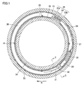
- FIG. 1 is a schematic cross-sectional view illustrating an example of a bearing device according to a first embodiment.
- FIG. 2 is a schematic cross-sectional view taken along line II-II in FIG.
- FIG. 6 is a schematic cross-sectional view showing a modification of the bearing device according to the first embodiment.
- FIG. 6 is a schematic cross-sectional view showing a modification of the bearing device according to the first embodiment.
- FIG. 6 is a schematic cross-sectional view showing a modification of the bearing device according to the first embodiment.
- FIG. 6 is a schematic cross-sectional view showing a modification of the bearing device according to the first embodiment.
- 6 is a schematic cross-sectional view showing a bearing device according to Embodiment 2.
- FIG. FIG. 8 is a perspective sectional view of the outer ring shown in FIG. 7.
- FIG. 6 is a schematic cross-sectional view showing a bearing device according to a third embodiment.
- FIG. 10 is a perspective sectional view of the outer
- the bearing device 10 mainly includes an angular ball bearing 11 (see FIG. 2; hereinafter simply referred to as the bearing 11), bearing spacers 33 and 34, and a lubricating oil supply unit 20 (see FIG. 2).
- the angular ball bearing 11 mainly includes an outer ring 13 as a fixed ring, an inner ring 14 as a rotating ring, a plurality of balls 15 as rolling elements, and a cage 16.
- the outer ring 13 has a first raceway surface 13A.
- the inner ring 14 has a second raceway surface 14A.
- the plurality of balls 15 are arranged with a contact angle between the first raceway surface 13A and the second raceway surface 14A.
- the back side the opposite side is referred to as the front side.
- the rolling race 13B of the ball 15 is formed on a partial region of the first raceway surface 13A by rotating the inner ring 14 in a state where a radial load and a thrust load are applied.
- the rolling trace 13B is formed on a region that can contact the rolling surface on the contact angle line A on the first raceway surface 13A.
- the inclination of the contact angle line A with respect to the axial direction of the bearing 11 (hereinafter simply referred to as the axial direction) can vary depending on the use conditions such as preload applied to the bearing 11, external load, and rotational speed. Therefore, the rolling trace 13B has a width in a direction along the first track surface 13A in a cross section perpendicular to the circumferential direction. 13 A of 1st track surfaces have the area
- the rolling trace 13B is formed over the entire circumference of the first raceway surface 13A in the circumferential direction.
- the cage 16 holds a plurality of balls 15 at regular intervals in the circumferential direction of the bearing 11.
- the cage 16 is disposed in a space formed between the outer ring 13 and the inner ring 14 and spaced from each of the outer ring 13 and the inner ring 14 in the radial direction.
- the end surface 16E of the cage 16 in the axial direction is formed on the inner side in the axial direction than the end surface (width surface) of the outer ring 13 and the end surface (width surface) of the inner ring 14 in the axial direction.
- the outer ring 13 is formed with a recess 17 extending at least in the axial direction of the angular ball bearing.
- the recess 17 is formed as a through hole, for example.
- One end 17 ⁇ / b> A in the axial direction of the recess 17 faces a space formed between the outer ring 13 and the inner ring 14.
- One end 17 ⁇ / b> A of the recess 17 faces a gap that is part of the space and is formed between the outer ring 13 and the cage 16.
- the other end 17B in the axial direction of the recess 17 is located outside the one end in the axial direction.
- the other end 17 ⁇ / b> B of the recess 17 is formed on the width surface of the outer ring 13.
- the width surface of the outer ring 13 is an end surface of the outer ring 13 in the axial direction and refers to a surface facing an outer ring spacer 33 described later.
- a recess is formed on the width surface of the outer ring 13, and the other end 17 ⁇ / b> B of the recess 17 is formed on a portion of the width surface of the outer ring 13 that forms the bottom surface of the recess.
- the hole axis B of the recess 17 is formed so as to extend along one direction intersecting with the axial direction, for example.
- An angle ⁇ formed by the hole axis B of the recess 17 with respect to the axial direction is, for example, 100 degrees or more and 170 degrees or less.
- the concave portion 17 includes a first portion including one end 17A and a second portion located on the outer ring spacer 33 side (upstream side of a supply passage described later) with respect to the first portion.
- the hole diameter of the first part of the recess 17 is smaller than the hole diameter of the second part of the recess 17.
- the respective hole diameters of the first part and the second part of the recess 17 are appropriately set according to the relationship between the surface tension resulting from the viscosity of the base oil and the discharge amount.
- the recess refers to a structure that is recessed with respect to a certain surface.
- An example of the concave portion in the present invention is a through-hole in which the concave portion reaches another surface.
- Another example of the recess in the present invention is a groove.
- the outer ring 13 is formed with a grease pocket 18 adjacent to the first raceway surface 13A on the back side in the axial direction.
- the grease pocket 18 is formed as a groove on the shoulder 13C of the outer ring 13 adjacent to the first raceway surface 13A of the outer ring 13 in the axial direction.
- the grease pocket 18 is formed along the circumferential direction of the outer ring 13. An end portion of the grease pocket 18 located on the inner side in the axial direction is connected to the first raceway surface 13A. An end portion of the grease pocket 18 located on the outer side in the axial direction is connected to the inner peripheral surface of the shoulder portion 13C.
- An end portion of the grease pocket 18 located on the outer side in the axial direction is formed at a position closer to the first track surface 13A than the end surface 16E of the cage 16.
- One end 17 ⁇ / b> A of the recess 17 is formed in the grease pocket 18.
- One end 17A of the recess 17 is formed, for example, on the end of the grease pocket 18 located outside the grease pocket 18 in the axial direction. In the cross section perpendicular to the circumferential direction, the outline of the one end 17A is, for example, curved.
- the outer ring 13 is further formed with a grease pocket 18 adjacent to the first raceway surface 13A on the front side in the axial direction, for example. That is, the two grease pockets 18 are formed adjacent to the first raceway surface 13A so as to sandwich the first raceway surface 13A in the axial direction.
- the grease pocket 18 located on the front side of the first raceway surface 13A has the same configuration as the grease pocket 18 located on the back side of the first raceway surface 13A.
- the bearing spacers 33 and 34 include an outer ring spacer 33 and an inner ring spacer 34.
- the outer ring spacer 33 is adjacent to the outer ring 13 in the axial direction.
- the width surface of the outer ring spacer 33 is in contact with the width surface of the outer ring 13.
- the inner ring spacer 34 is adjacent to the inner ring 14 in the axial direction.
- the width surface of the inner ring spacer 34 is in contact with the width surface of the inner ring 14. Desired grease is enclosed in the bearing 11 in advance.
- Lubricating oil supply unit 20 includes a supplying unit that supplies lubricating oil to the space sandwiched between outer ring 13 and inner ring 14, and a power generation unit that generates electric power for operating the supplying unit. As shown in FIGS. 1 and 2, the lubricating oil supply unit 20 is disposed between the outer ring spacer 33 and the inner ring spacer 34 except for a part of a discharge tube 32 described later. Between the outer ring spacer 33 and the inner ring spacer 34, an annular housing composed of the housing main body 21 and the lid body 22 is formed. As shown in FIG. 1, the lubricating oil supply unit 20 is disposed in the housing body 21 and the lid body 22 except for a part of a discharge tube 32 described later.
- the lubricating oil supply unit 20 mainly includes a power generation unit 25, a power supply circuit 26 including a charging unit, a control circuit 27, a driving circuit 28, a pump 29, and a lubricating oil tank 30 in the circumferential direction.
- the control circuit 27, the drive circuit 28, the pump 29, the lubricating oil tank 30, the suction tube 31, and the discharge tube 32 serve as a supply unit that supplies lubricating oil to a space sandwiched between the outer ring 13 and the inner ring 14. It is composed.
- the power generation unit 25 is provided so as to generate electric power for operating the supply unit of the lubricating oil supply unit 20 and supply the electric power to the supply unit.
- the power generation unit 25 for example, a unit that generates power by the Seebeck effect can be used.
- the power generation unit 25 includes a heat conductor 23 a connected to the outer ring spacer 33, a heat conductor 23 b disposed with a gap 36 between the inner ring spacer 34, and It has a thermoelectric element 24 (an element utilizing the Seebeck effect of a Peltier element) that is disposed so as to connect between the heat conductor 23a and the heat conductor 23b and is closely fixed to the heat conductors 23a and 23b.
- the power generation unit 25 supplies power to the lubricating oil supply unit 20 as follows. As shown in FIG. 1, when a rolling bearing device is used as the bearing device 10, the temperature of the inner ring 14 and the outer ring 13 rises due to frictional heat with the balls 15 (see FIG. 2). Normally, the outer ring 13 is dissipated by heat conduction because it is incorporated in the housing of the device. Therefore, a temperature difference occurs between the inner ring 14 and the outer ring 13 (the temperature of the inner ring 14 is higher than the temperature of the outer ring 13). The temperature is conducted to each heat conductor 23a, 23b. The heat conductors 23a and 23b are disposed so as to penetrate the inner peripheral surface and the outer peripheral surface of the housing body 21, respectively.
- thermoelectric element 24 disposed between the heat conductor 23a (heat sink) connected to the outer ring 13 via the outer ring spacer 33 and the heat conductor 23b located on the inner ring spacer 34 side (inner ring 14 side). A temperature difference occurs between both end faces of 24. For this reason, the thermoelectric element 24 can generate power by the Seebeck effect.
- the power generation unit 25 is connected to the power supply circuit 26.
- the power supply circuit 26 is provided so as to be able to store electric charges generated by the power generation unit 25. Specifically, the electric charge is stored in a power storage unit such as a storage battery or a capacitor included in the power supply circuit 26.
- the power supply circuit 26 is connected to the control circuit 27.
- the power supply circuit 26 is electrically connected to the drive circuit 28 and the pump 29 via the control circuit 27, and is provided so as to be able to supply power thereto.
- the control circuit 27 is capable of acquiring data relating to the lubricating oil supply status in the lubricating oil supply unit 20 and outputting the data to the outside of the control circuit 27 as will be described later.
- the control circuit 27 includes a program storage unit that holds a control program, and an arithmetic unit (microcomputer) that is connected to the program storage unit and executes the control program.
- Various parameters related to the forward rotation operation of the pump 29 by the control circuit 27, for example, the supply start timing of the lubricant to the bearing 11, the supply timing (interval), the drive time of the pump 29 for supplying the lubricant, and the lubricant And the like can be set in advance.
- the control circuit 27 is connected to the drive circuit 28.
- the drive circuit 28 is a circuit for operating a pump 29 such as a micropump.
- the drive circuit 28 may include, for example, an arbitrary sensor (a bearing temperature sensor, a bearing rotation sensor, a lubricant remaining amount sensor, a lubricant temperature sensor, etc.). Signals from these sensors may be input to a calculation unit (microcomputer) of the drive circuit 28, and the pump 29 may be automatically controlled in accordance with the temperature of the bearing 11 and its rotation state to adjust the supply amount of the lubricating oil.
- the pump 29 is, for example, a rotary pump, for example, a trochoid pump.
- the pump 29 is controlled by the control circuit 27 via the drive circuit 28.
- a suction tube 31 connected to the bag body of the lubricating oil tank 30 and a discharge tube 32 (nozzle) for supplying lubricating oil from the pump 29 to the inside of the bearing 11 are connected to the pump 29.
- the discharge port of the discharge tube 32 (the end opposite to the root portion connected to the pump 29) is on the width surface of the outer ring 13 rather than the width surface of the outer ring spacer 33 in the axial direction. It protrudes into the formed recess.
- the discharge port of the discharge tube 32 is connected to the other end 17 ⁇ / b> B of the recess 17 formed on the width surface of the outer ring 13. Thereby, the lubricating oil discharged from the discharge port of the discharge tube 32 flows into the recess 17 from the other end 17B, and flows out into the grease pocket 18 from the one end 17A.
- the diameter of the discharge tube 32 is appropriately set according to the relationship between the surface tension resulting from the viscosity of the base oil and the discharge amount.
- Lubricating oil tank 30 stores the same type of lubricating oil as the base oil of grease sealed in bearing 11.
- the power generation unit 25, the power supply circuit 26, the control circuit 27, the drive circuit 28, the pump 29, and the lubricating oil tank 30 are arranged in the circumferential direction in the housing body 21.
- the housing body 21 has an open surface opposite to the bearing 11 and has a U-shaped cross section.
- the lid 22 is configured to close the opening of the housing body 21 and be detachable from the housing body 21.
- the housing body 21 and the lid body 22 may be made of any material, but may be made of, for example, a resin material, more preferably a thermoplastic resin.
- a tapped hole 35 (see FIG. 1) is formed in the housing main body 21, and the lid 22 of the housing may be fixed to the tapped hole 35 with a screw.
- the housing body 21 is fixed to the outer ring spacer 33.
- a gap 36 is formed between the housing body 21 and the inner ring spacer 34.
- the bearing device 10 includes a control circuit 27 serving as a supply unit that supplies lubricating oil to the angular ball bearing 11 and the space sandwiched between the outer ring 13 and the inner ring 14.
- a drive circuit 28 a pump 29, a lubricating oil tank 30, a suction tube 31, and a discharge tube 32.
- the bearing 11 is an outer ring 13 as a fixed ring having a first raceway surface 13A, and a rotary wheel having a second raceway surface 14A arranged at a distance from the first raceway surface 13A in the radial direction of the outer ring 13.
- a recess 17 is formed in the outer ring 13.
- One end 17A of the recess 17 faces the first space portion located on the outer ring 13 side with respect to the outer diameter surface of the cage 16 in the space, specifically, the space.
- the other end 17 ⁇ / b> B of the recess 17 is positioned outside the one end 17 ⁇ / b> A in the axial direction of the bearing 11.
- the supply part is provided so as to be able to supply lubricating oil to the space, particularly the first space part, via the recess 17.
- the supply unit supplies the lubricating oil to the space, particularly the first space portion, via the recess 17. be able to.
- the second space portion is located closer to the inner ring 14 than the outer diameter surface of the cage 16 and outside the end surface 16E of the cage 16 in the axial direction.
- the air curtain inhibits lubricating oil from flowing through the second space portion in the axial direction.
- the bearing device 10 In the first space portion, even when the inner ring 14 and the cage 16 are rotated at a high speed, there is no air curtain that can hinder the flow of the lubricating oil in the axial direction. Therefore, according to the bearing device 10, the lubricating oil can be efficiently supplied to the first space portion of the space via the one end 17A of the recess 17 formed in the outer ring 13 without being affected by the air curtain. it can.
- the lubricating oil supplied to the first space portion can be wet and spread on the first track surface 13A connected to the first space portion without being affected by the air curtain. That is, according to the bearing device 10, the lubricating oil can be supplied to the first raceway surface 13A through the first space portion without being affected by the air curtain.
- the bearing device 10 has a longer life compared to a bearing device that supplies lubricating oil to the raceway surface through the second space portion.
- the bearing device 10 further includes a cage 16 that holds a plurality of balls 15.
- the one end 17A of the recess 17 is formed on the inner side of the end surface 16E of the cage 16 in the axial direction. That is, the one end 17A faces the minute space portion located on the inner side in the axial direction from the end surface 16E of the retainer 16 in the first space portion. Therefore, the bearing device 10 can supply the lubricating oil to the first raceway surface 13A through the minute space portion of the first space portion without being affected by the air curtain. Further, in this case, when the one end 17A is formed outside the end surface 16E of the retainer 16 in the axial direction, that is, the one end 17A is positioned outside the minute space portion in the axial direction.
- the distance between the one end 17 ⁇ / b> A and the first track surface 13 ⁇ / b> A is shorter than when formed in another space portion within one space portion.
- the bearing device 10 can supply the lubricating oil from the recess 17 to the first raceway surface 13A more quickly.
- the bearing device 10 has a longer life as compared with the bearing device 10 in which the one end 17A is formed on the outer ring 13 outside the end surface 16E in the axial direction.
- one end 17 ⁇ / b> A of the recess 17 is formed in a region other than the rolling trace 13 ⁇ / b> B of the first raceway surface 13 ⁇ / b> A in the outer ring 13.
- the one end 17 ⁇ / b> A is formed on the rolling trace 13 ⁇ / b> B, only a part of the rolling surface of the ball 15 is pressed against the first raceway surface 13 ⁇ / b> A, stress concentration occurs, and a local area between the outer ring 13 and the ball 15 is generated. This may cause an oil film breakage, metal contact, excessive heat generation, and surface damage.
- the bearing device 10 since the one end 17A is formed in the outer ring 13 in a region other than the rolling trace 13B of the first raceway surface 13A, the bearing having the one end 17A formed on the rolling trace 13B. Compared with the device 10, early damage of the bearing 11 is suppressed.
- the outer ring 13 is adjacent to the first raceway surface 13 ⁇ / b> A on the side (back side) where the contact angle is generated in the axial direction and is along the circumferential direction of the outer ring 13.
- a grease pocket 18 is formed as a groove portion extending in this manner. Grease may be enclosed in the grease pocket 18.
- one end 17 ⁇ / b> A of the recess 17 is formed in the grease pocket 18. That is, the recess 17 is connected to the grease pocket 18. Therefore, the lubricating oil supplied from the supply part into the first space portion of the space via the one end 17A can be temporarily stored in the grease pocket 18 after first being discharged into the grease pocket 18. .
- the lubricating oil in the grease pocket 18 spreads as appropriate on the first raceway surface 13A including the rolling trace 13B. Therefore, according to the bearing device 10, it is possible to more reliably prevent the oil film from being cut, so that the lifetime is longer than that of the bearing device 10 in which the grease pocket 18 is not formed.
- the concave portion 17 is formed as a through hole formed in the outer ring 13 as a fixed ring.
- One end 17A of the recess 17 can be formed in a region closer to the rolling trace 13B than the end face 16E of the cage 16.
- the lubricating oil is more reliably supplied to the first raceway surface 13 ⁇ / b> A via the recess 17. be able to.
- the recess 17 does not cause the above damage.
- the distance between the outer ring 13 and the retainer 16 in the radial direction of the bearing 11 is shorter than the outer diameter of the discharge tube 32, and the discharge tube 32 is directly inserted into the gap between the outer ring 13 and the retainer 16. Even when this is difficult, lubricating oil can be supplied into the gap through the recess 17 as a through hole.
- the other end 17B of the recess 17 is formed on the width surface of the outer ring 13 as a fixed ring.
- the recess 17 is formed linearly along the first direction. That is, the hole axis B of the recess 17 extends along the first direction.
- the concave portion 17 can be easily formed by, for example, drilling along the first direction.
- the first direction forms an angle ⁇ of 100 degrees to 170 degrees with respect to the axial direction. In this way, the concave portion 17 extending from the width surface of the outer ring 13 into the grease pocket 18 can be easily formed.
- the bearing device 10 includes an outer ring spacer 33 as a fixed ring spacer adjacent to the outer ring 13 in the axial direction, and an outer ring spacer 33 adjacent to the inner ring 14 in the axial direction and in the radial direction. It further includes an inner ring spacer 34 that is disposed at an interval, and a power generation unit 25 that generates electric power for operating the supply unit. Therefore, the bearing device 10 does not need to take in the electric power for operating the said supply part from the outside.
- the supply unit and the power generation unit 25 constitute a lubricating oil supply unit 20.
- the lubricating oil supply unit 20 is mainly disposed between the outer ring spacer 33 and the inner ring spacer 34.
- the bearing device 10 does not need to provide a space for arranging the lubricating oil supply unit 20 in the bearing 11.
- the outer ring spacer 33 and the inner ring spacer 34 are configured as so-called intermediate spacers, the two bearings 11 arranged so as to sandwich the outer ring spacer 33 and the inner ring spacer 34 in the axial direction are provided. It is also possible to supply lubricating oil.
- the angular ball bearing 11 of the bearing device 10 includes an outer ring 13 as a fixed ring and an inner ring 14 as a rotating ring.
- Such a bearing device 10 is suitable, for example, for a machine tool in which the inner ring 14 is rotated at a high speed and a preload or an external load is applied to the bearing 11.
- the one end 17 ⁇ / b> A of the recess 17 may not be formed in the grease pocket 18.
- One end 17 ⁇ / b> A of the recess 17 may be formed at an arbitrary position in the axial direction in the outer ring 13.
- the one end 17 ⁇ / b> A of the recess 17 may be formed on the outer ring 13 on the outer side in the axial direction than the end surface 16 ⁇ / b> E of the cage 16.
- the bearing device 10 thus configured can also efficiently supply the lubricating oil from the recess 17 to the first raceway surface 13A through the first space portion without being affected by the air curtain. Compared with the bearing device in which the lubricating oil is supplied inward of the outer diameter surface of the cage in the direction, the service life is longer.
- the outer ring 13 is not formed with the grease pocket 18, and one end 17 ⁇ / b> A of the recess 17 may be formed on the shoulder 13 ⁇ / b> C adjacent to the first raceway surface 13 ⁇ / b> A. Even if it does in this way, without being influenced by an air curtain, lubricating oil can be efficiently supplied to 13 A of 1st track surfaces from the recessed part 17 through the said 1st space part. As a result, the bearing device 10 has a longer life compared to the bearing device in which the lubricating oil is supplied to the inside of the outer diameter surface of the cage in the radial direction.
- the recess 17 may be formed so that the hole axis B is bent.
- the recess 17 may be formed in an L shape.
- the concave portion 17 includes a portion having one end 17A and a hole axis extending along the radial direction, and a portion having the other end 17B and the hole axis extending along the axial direction. May be.
- the recessed part 17 may be formed in the U-shape in the cross section perpendicular
- the other end 17 ⁇ / b> B of the recess 17 may not be formed on the width surface of the outer ring 13.
- the other end 17B may be formed, for example, on the inner peripheral surface of the outer ring 13 outside the end surface 16E of the retainer 16 in the axial direction.
- the discharge tube 32 may be formed so that the discharge port 32A is connected to the other end 17B.
- one end 17 ⁇ / b> A of the recess 17 is formed on the first track surface 13 ⁇ / b> A located on the side (front side) where the contact angle does not occur with respect to the rolling trace 13 ⁇ / b> B in the axial direction. Also good. Even if it does in this way, lubricating oil can be efficiently supplied to 13 A of 1st track surfaces from the recessed part 17 through the said 1st space part, without being influenced by an air curtain. Further, since the one end 17A is formed in a region other than the rolling trace 13B even on the first raceway surface 13A, the bearing device 10 is prevented from being damaged due to the concave portion 17.
- the other end 17B of the recess 17 may be formed on the end surface of the outer ring 13 located on the front side in the axial direction. In this way, compared to the case where the one end 17A and the other end 17B are formed so as to sandwich the contact angle line A in the axial direction, the extending distance from the other end 17B to the one end 17A of the recess 17 is increased. Can be shortened. Therefore, the bearing device 10 can quickly supply the lubricating oil from the recess 17 to the first raceway surface 13A.
- the angular ball bearing 11 of the bearing device 10 may include an inner ring 14 as a fixed ring and an outer ring 13 as a rotating ring.
- a recess 17 is formed in the inner ring 14 as a fixed ring.
- the bearing 11 when the outer ring 13 and the cage 16 are rotated at a high speed, the bearing 11 is located outside in the radial direction with respect to the inner diameter surface of the cage 16 facing the inner ring 14 as a fixed ring, and is held in the axial direction.
- An air curtain may be formed outside the end face 16E of the vessel 16.
- the lubricating oil flows at least in the axial direction. There is no air curtain that can be blocked. Therefore, according to the bearing device 10 in which the lubricating oil is supplied to the third space portion via the one end 17A of the recess 17 formed in the inner ring 14, the supply of the lubricating oil is prevented from being hindered by the air curtain. ing.
- the lubricating oil supplied to the third space portion can be wet and spread on the first track surface 13A connected to the third space portion.
- the bearing device 10 has a longer life than the bearing device in which the lubricating oil is supplied between the outer ring 13 as the rotating wheel and the cage 16 in the radial direction.
- 3 to 6 show cross sections perpendicular to the circumferential direction of the bearing device 10 as in FIG.
- the bearing device 110 basically has the same configuration as that of the bearing device 10 according to the first embodiment, but differs in that a discharge port 32A of a discharge tube 32 as a nozzle is disposed in the bearing 11.
- the lubricating oil supply unit 120 of the bearing device 110 basically has the same configuration as the lubricating oil supply unit 20 according to the first embodiment, but the discharge port 32A of the discharge tube 32 is disposed in the space of the bearing 11. Different in that it is.
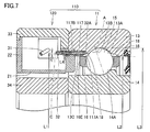
- FIG. 7 shows a cross section perpendicular to the circumferential direction of the bearing device 110.
- the bearing device 110 includes an angular ball bearing 11, an outer ring spacer 33, an inner ring spacer 34, and the supply unit.
- the angular ball bearing 11 is a rotating wheel having an outer ring 13 as a fixed ring having a first raceway surface 13A, and a second raceway surface 14A arranged at a distance from the first raceway surface 13A in the radial direction of the outer ring 13.
- the outer ring spacer 33 is adjacent to the outer ring 13 in the axial direction of the angular ball bearing 11.
- the inner ring spacer 34 is disposed adjacent to the inner ring 14 in the axial direction and spaced from the outer ring spacer 33 in the radial direction.
- the supply unit is disposed between the outer ring spacer 33 and the inner ring spacer 34.
- the supply unit supplies the lubricating oil to a gap sandwiched between the cage 16 and the outer ring 13, that is, the first space portion.
- the supply unit includes a discharge tube 32 serving as a nozzle disposed in the gap and having a discharge port 32A for discharging lubricating oil. That is, the discharge port 32A is formed inside the end surface 16E of the retainer 16 in the axial direction.
- the outer ring 13 of the bearing device 110 has a nozzle insertion recess 117 into which a part of the discharge tube 32 is inserted.
- the nozzle insertion recess 117 has basically the same configuration as the recess 17 in the bearing device 10 and is different in that a part of the discharge tube 32 is inserted.
- One end 117 ⁇ / b> A in the axial direction of the nozzle insertion recess 117 faces the gap sandwiched between the outer ring 13 and the cage 16, that is, the minute space portion of the first space portion.
- the other end 117B in the axial direction of the nozzle insertion recess 117 is located outside the one end 117A in the axial direction.
- the other end 117B of the nozzle insertion recess 117 is formed, for example, on the end surface of the shoulder 13C located outside the one end 117A in the axial direction.
- the nozzle insertion recess 117 is formed in the shoulder 13C of the outer ring 13 as a through hole.
- the hole axis of the nozzle insertion recess 117 is, for example, along the axial direction.
- the hole diameter of the nozzle insertion recess 117 is longer than the outer diameter of the discharge tube 32.
- the outer ring 13 is adjacent to the first raceway surface 13 ⁇ / b> A on the side where the contact angle occurs in the axial direction and is a grease pocket as a groove portion along the circumferential direction of the outer ring 13. 18 is formed.
- the discharge port 32A is disposed in the grease pocket 18.
- the bearing 11 includes an outer ring 13 as a fixed ring and an inner ring 14 as a rotating ring.
- the central axis C of the discharge tube 32 is along the hole axis of the nozzle insertion recess 117, for example, along the axial direction.
- the discharge port 32A of the discharge tube 32 is disposed at a position closer to the one end 117A than the other end 117B of the nozzle insertion recess 117, for example. That is, the discharge port 32 ⁇ / b> A is formed at a position closer to the first track surface 13 ⁇ / b> A than the end surface 16 ⁇ / b> E of the cage 16.
- a part of the discharge port 32A located on the side of the cage 16 protrudes into the grease pocket 18, for example. That is, the discharge port 32A is disposed in the minute space portion of the first space portion.
- the bearing device 110 the lubricating oil discharged from the discharge port 32A can be supplied to the first raceway surface 13A from within the grease pocket 18 without being affected by the air curtain. Therefore, the bearing device 110 can achieve the same effect as the bearing device 10.
- L4 in the radial direction from the surface satisfies the relationship L2 + r + L4 ⁇ L1 ⁇ L3.
- the distance L1 corresponds to the radius of a circle passing through the center of the discharge port 32A with the center axis of the bearing 11 as the center.
- the distance L4 corresponds to the distance in the radial direction between the inner peripheral surface of the shoulder portion 13C of the outer ring 13 and the outer diameter surface of the cage 16.
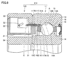
- the bearing device 210 basically has the same configuration as the bearing device 110 according to the second embodiment, but is different in that the nozzle insertion recess 117 is formed as a groove instead of a through hole.
- the nozzle insertion recess 117 is formed as a groove on the inner peripheral surface of the outer ring 13 as a fixed ring facing the inner ring 14 as a rotating ring.
- FIG. 9 shows a cross section perpendicular to the circumferential direction of the bearing device 210.
- the nozzle insertion recess 117 is a groove formed in a concave shape with respect to the inner peripheral surface of the shoulder 13 ⁇ / b> C of the outer ring 13.
- the nozzle insertion recess 117 is formed to extend along the axial direction. In the cross section perpendicular to the axial direction, the inner surface of the nozzle insertion recess 117 forms, for example, a semicircular arc.
- One end 117 ⁇ / b> A of the nozzle insertion recess 117 is formed in the grease pocket 18. That is, the one end 117A is formed at a position closer to the first track surface 13A than the end surface 16E of the cage 16, and faces the minute space portion of the first space portion.
- the nozzle insertion recess 117 is connected to the grease pocket 18.
- the other end 17B of the nozzle insertion recess 117 is formed, for example, on the end surface of the shoulder 13C located outside the one end 117A in the axial direction.
- the hole axis of the nozzle insertion recess 117 is, for example, along the axial direction.
- the nozzle insertion recess 117 is provided so as to accommodate at least a part of the discharge tube 32.
- the nozzle insertion recess 117 is provided so as to accommodate a part of the discharge tube 32 that includes the discharge port 32A and is positioned on the outer ring 13 side in the radial direction.
- the central axis C of the discharge tube 32 is along the hole axis of the nozzle insertion recess 117, for example, along the axial direction.
- the discharge port 32A of the discharge tube 32 is disposed at a position closer to the one end 117A than the other end 117B of the nozzle insertion recess 117, for example.
- a part of the discharge port 32A located on the side of the cage 16 protrudes into the grease pocket 18, for example. That is, the discharge port 32A is disposed in the minute space portion of the first space portion.
- the bearing device 110 the lubricating oil discharged from the discharge port 32A can be supplied to the first raceway surface 13A including the rolling trace 13B without being affected by the air curtain. Therefore, the bearing device 210 can achieve the same effect as the bearing devices 10 and 110.
- the bearing devices 110 and 210 can be modified in the same manner as the modified example of the bearing device 10 described above.
- one end 117 ⁇ / b> A of the nozzle insertion recess 117 may not be formed in the grease pocket 18.
- One end 117A of the nozzle insertion recess 117 may be formed at an arbitrary position in the axial direction.
- the one end 117A of the nozzle insertion recess 117 may be formed outside the end surface 16E of the cage 16 in the axial direction.
- No grease pocket 18 is formed in the outer ring 13, and one end 117A of the nozzle insertion recess 117 may be formed on the shoulder 13C adjacent to the first raceway surface 13A.
- One end 117A of the nozzle insertion recess 117 may be formed on the first track surface 13A located on the side (front side) where the contact angle does not occur with respect to the rolling trace 13B in the axial direction.
- the hole axis of the nozzle insertion recess 117 may be formed to be inclined with respect to the axial direction.
- the present invention is particularly advantageously applied to a bearing device including an angular ball bearing in which a rotating wheel is rotated at a high speed.
Landscapes
- Engineering & Computer Science (AREA)
- General Engineering & Computer Science (AREA)
- Mechanical Engineering (AREA)
- Rolling Contact Bearings (AREA)
Abstract
従来の軸受装置よりも長寿命な軸受装置を提供する。アンギュラ玉軸受(11)と、外輪間座(33)と、内輪間座(34)と、外輪間座(33)と内輪間座(34)との間に配置されており、アンギュラ玉軸受(11)の保持器(16)と外輪(13)との間に挟まれている隙間に潤滑油を供給する供給部とを備える。上記供給部は、上記隙間内に配置されており潤滑油を吐出する吐出口(32A)を有するノズルとしての吐出チューブ(32)を含む。
Description
本発明は、軸受装置に関し、特にアンギュラ玉軸受と、該アンギュラ玉軸受に潤滑油を供給する供給部とを備える軸受装置に関する。
転がり軸受内に潤滑油を供給する給油ユニットを該転がり軸受の内部に組み込んだ軸受装置が知られている。特開2014-37879号公報(特許文献1)に開示された軸受装置は、軸受に隣接する間座内に配置された潤滑油タンクとポンプとを含む。この軸受装置では、ポンプを間欠的に動作させることにより、軸受に潤滑油を長期間安定して供給できる。
一方で、従来の軸受装置よりもさらに長寿命な軸受装置が求められている。
本発明は、上記のような課題を解決するためになされたものである。本発明の主たる目的は、従来の軸受装置よりも長寿命な軸受装置を提供することにある。
本発明は、上記のような課題を解決するためになされたものである。本発明の主たる目的は、従来の軸受装置よりも長寿命な軸受装置を提供することにある。
本発明に係る軸受装置は、第1軌道面を有する固定輪と、固定輪の径方向において第1軌道面と間隔を隔てて配置されている第2軌道面を有する回転輪と、第1軌道面と第2軌道面との間に接触角を持って配置される複数の転動体と、複数の転動体を保持する保持器とを含むアンギュラ玉軸受と、アンギュラ玉軸受の軸方向において固定輪に隣接している固定輪間座と、軸方向において回転輪に隣接して、かつ径方向において固定輪間座と間隔を隔てて配置されている回転輪間座と、固定輪間座と回転輪間座との間に配置されており、保持器と固定輪との間に挟まれている隙間に潤滑油を供給する供給部とを備える。供給部は、隙間内に配置されており潤滑油を吐出する吐出口を有するノズルを含む。
本発明によれば、従来の軸受装置よりも長寿命な軸受装置を提供することができる。
以下、図面に基づいて本発明の実施の形態を説明する。なお、以下の図面において同一または相当する部分には同一の参照番号を付しその説明は繰返さない。
(実施の形態1)
<軸受装置の構成>
図1および図2を参照して、実施の形態1に係る軸受装置10について説明する。軸受装置10は、アンギュラ玉軸受11(図2参照。以下、単に軸受11とよぶ。)と、軸受間座33,34と、潤滑油供給ユニット20(図2参照)とを主に備える。
<軸受装置の構成>
図1および図2を参照して、実施の形態1に係る軸受装置10について説明する。軸受装置10は、アンギュラ玉軸受11(図2参照。以下、単に軸受11とよぶ。)と、軸受間座33,34と、潤滑油供給ユニット20(図2参照)とを主に備える。
図2に示されるように、アンギュラ玉軸受11は、固定輪としての外輪13と、回転輪としての内輪14と、転動体としての複数の玉15と、保持器16とを主に備える。外輪13は第1軌道面13Aを有している。内輪14は第2軌道面14Aを有している。複数の玉15は、第1軌道面13Aと第2軌道面14Aとの間に接触角を持って配置されている。以下、各玉15の接触角線A(図2参照)が軸受11の径方向に対して傾いている側を背面側、その反対側を正面側とよぶ。軸受11では、ラジアル荷重およびスラスト荷重が印加された状態で内輪14が回転されることにより、第1軌道面13Aの一部領域上に玉15の転走跡13Bが形成される。転走跡13Bは、第1軌道面13Aにおいて接触角線A上の転走面と接触し得る領域上に形成される。軸受11の軸方向(以下、単に軸方向とよぶ)に対する接触角線Aの傾きは、軸受11に印加される予圧、外部荷重、回転速度などの使用条件に応じて変動し得る。そのため、転走跡13Bは、上記周方向に垂直な断面において第1軌道面13Aに沿った方向に幅を有する。第1軌道面13Aは、転走跡13Bが形成されていない領域を有している。転走跡13Bは、上記周方向において第1軌道面13Aの全周に渡って形成される。
保持器16は、軸受11の周方向において複数の玉15を一定間隔に保持している。保持器16は、外輪13と内輪14との間に形成される空間内に、外輪13および内輪14の各々と上記径方向において間隔を隔てて配置されている。上記軸方向における保持器16の端面16Eは、該軸方向における外輪13の端面(幅面)および内輪14の端面(幅面)よりも、該軸方向において内側に形成されている。
図2に示されるように、外輪13には、少なくともアンギュラ玉軸受の軸方向に延びる凹部17が形成されている。凹部17は、例えば貫通孔として形成されている。凹部17の上記軸方向の一端17Aは、外輪13と内輪14との間に形成される空間に面している。凹部17の一端17Aは、上記空間の一部であって外輪13と保持器16との間に形成される隙間に面している。凹部17の上記軸方向の他端17Bは、上記軸方向において一端よりも外側に位置している。凹部17の他端17Bは、外輪13の幅面上に形成されている。ここで、外輪13の幅面とは、上記軸方向における外輪13の端面であって、後述する外輪間座33に面している面を指す。外輪13の幅面には例えば凹部が形成されており、凹部17の他端17Bは外輪13の幅面のうち当該凹部の底面を成している部分上に形成されている。凹部17の孔軸Bは、例えば上記軸方向に対して交差する1つの方向に沿って延びるように形成されている。凹部17の孔軸Bが上記軸方向に対して成す角度θは、例えば100度以上170度以下である。凹部17は、一端17Aを含む第1部と、第1部よりも外輪間座33側(後述する供給通路の上流側)に位置する第2部とを有する。凹部17の第1部の孔径は、凹部17の第2部の孔径よりも小さい。凹部17の第1部および第2部の各孔径は、基油の粘度に起因する表面張力と吐出量との関係により、適宜設定される。本発明において、凹部とは、ある面に対して凹んでいる構造を指す。本発明における凹部の一例は、当該凹みが他の面まで達して成る貫通孔である。本発明における凹部の他の例は、溝である。
図2に示されるように、外輪13には、上記軸方向において背面側に第1軌道面13Aと隣接するグリースポケット18が形成されている。グリースポケット18は、上記軸方向において外輪13の第1軌道面13Aと隣接する外輪13の肩部13C上に溝部として形成されている。グリースポケット18は外輪13の周方向に沿うように形成されている。上記軸方向において内側に位置するグリースポケット18の端部は、第1軌道面13Aと接続されている。上記軸方向の外側に位置するグリースポケット18の端部は、肩部13Cの内周面と接続されている。上記軸方向の外側に位置するグリースポケット18の端部は、保持器16の上記端面16Eよりも第1軌道面13Aに近い位置に形成されている。凹部17の一端17Aは、該グリースポケット18内に形成されている。凹部17の一端17Aは、例えばグリースポケット18の上記軸方向の外側に位置するグリースポケット18の端部上に形成されている。上記周方向に垂直な断面において、一端17Aの外形線は例えば曲線状である。
図2に示されるように、外輪13には、例えば上記軸方向において正面側に第1軌道面13Aと隣接するグリースポケット18がさらに形成されている。つまり、2つのグリースポケット18が、上記軸方向において第1軌道面13Aを挟むように、第1軌道面13Aに隣接して形成されている。第1軌道面13Aよりも正面側に位置するグリースポケット18は、第1軌道面13Aよりも背面側に位置する上記グリースポケット18と同様の構成を有している。
軸受間座33,34は、外輪間座33と内輪間座34とを含む。外輪間座33は、上記軸方向において外輪13と隣接している。外輪間座33の幅面は外輪13の幅面と接触している。内輪間座34は、上記軸方向において内輪14と隣接している。内輪間座34の幅面は内輪14の幅面と接触している。軸受11には、予め所望のグリースが封入されている。
潤滑油供給ユニット20は、外輪13と内輪14との間に挟まれている上記空間に潤滑油を供給する供給部と、該供給部を作動させるための電力を発生させる発電部とを含む。図1および図2に示されるように、潤滑油供給ユニット20は、後述する吐出チューブ32の一部を除き、外輪間座33と内輪間座34との間に配置されている。外輪間座33と内輪間座34との間には、ハウジング本体21および蓋体22から成る円環状のハウジングが形成されている。図1に示されるように、潤滑油供給ユニット20は、後述する吐出チューブ32の一部を除き、ハウジング本体21および蓋体22内に配置されている。
潤滑油供給ユニット20は、円周方向に発電部25、充電部を含む電源回路26、制御回路27、駆動回路28、ポンプ29、および潤滑油タンク30を主に備える。制御回路27、駆動回路28、ポンプ29、および潤滑油タンク30、吸込みチューブ31、および吐出チューブ32は、外輪13と内輪14との間に挟まれている空間に潤滑油を供給する供給部を構成している。
発電部25は、潤滑油供給ユニット20の上記供給部を作動させるための電力を発生させ、かつ該電力を供給部に供給可能に設けられている。発電部25としては、例えばゼーベック効果によって発電を行うものを使用することができる。具体的には、図1に示すように、発電部25は、外輪間座33に接続された熱伝導体23aと、内輪間座34と隙間36を空けて配置された熱伝導体23bと、熱伝導体23aと熱伝導体23bとの間を接続するように配置され、熱伝導体23a,23bと密着固定された熱電素子24(ペルチェ素子のゼーベック効果を利用した素子)とを有する。
発電部25は、以下のようにして潤滑油供給ユニット20に電力を供給する。図1に示すように軸受装置10として転がり軸受装置を使用する場合、玉15(図2参照)との摩擦熱により内輪14と外輪13の温度が上昇する。通常、外輪13は機器のハウジングに組み込まれるため熱伝導により放熱される。そのため、内輪14と外輪13との間で温度差が生じる(外輪13の温度に対して内輪14の温度の方が高い)。その温度が各熱伝導体23a,23bに伝導される。熱伝導体23a,23bは、それぞれハウジング本体21の内周面と外周面とを貫通するように配置されている。そのため、外輪間座33を介して外輪13と接続された熱伝導体23a(ヒートシンク)と、内輪間座34側(内輪14側)に位置する熱伝導体23bとの間に配置された熱電素子24の両端面には温度差が生じる。このため、熱電素子24ではゼーベック効果により発電を行うことができる。このような発電部25を用いることにより、外部から潤滑油供給ユニット20に電力を供給する必要がないため、軸受装置10へ外部から電力を供給するための電線を取り付ける必要がない。発電部25は電源回路26に接続されている。
電源回路26は、発電部25によって発生した電荷を蓄電可能に設けられている。具体的には、当該電荷は電源回路26に含まれる蓄電池やコンデンサなどの蓄電部に蓄電される。電源回路26は制御回路27に接続されている。電源回路26は、制御回路27を介して駆動回路28およびポンプ29に電気的に接続されており、これらに対し電力を供給可能に設けられている。
制御回路27は、後述するように潤滑油供給ユニット20における潤滑油の供給状況に関するデータを取得するとともに、当該データを制御回路27の外部へ出力可能になっている。制御回路27は、制御プログラムが保持されるプログラム記憶部および当該プログラム記憶部と接続され当該制御プログラムを実行する演算部(マイコン)とを含む。制御回路27により、ポンプ29の正転動作に係る各種パラメータ、例えば軸受11への潤滑油の供給開始時期、供給タイミング(インターバル)、潤滑油の供給のためのポンプ29の駆動時間、および潤滑油の供給量など、を予め設定することができる。制御回路27は駆動回路28に接続されている。
駆動回路28はマイクロポンプなどのポンプ29を動作させるための回路である。駆動回路28は、例えば、任意のセンサ(軸受温度センサ、軸受回転センサ、潤滑油残量センサ、潤滑油温度センサ等)を備えていてもよい。これらのセンサからの信号が駆動回路28の演算部(マイコン)に入力され、軸受11の温度及びその回転状況に応じてポンプ29を自動制御し、潤滑油の供給量を調整してもよい。
ポンプ29は、例えば回転式ポンプであり、例えばトロコイドポンプである。ポンプ29は、駆動回路28を介して制御回路27により制御される。ポンプ29には、潤滑油タンク30の袋体に接続された吸込みチューブ31と、当該ポンプ29から軸受11の内部に潤滑油を供給するための吐出チューブ32(ノズル)とが接続されている。図2に示されるように、吐出チューブ32の吐出口(ポンプ29と接続された根元部と反対側の端部)は、上記軸方向において外輪間座33の幅面よりも外輪13の幅面上に形成された当該凹部内に突出している。吐出チューブ32の吐出口は、外輪13の幅面上に形成されている凹部17の他端17Bと接続されている。これにより、吐出チューブ32の吐出口から吐出された潤滑油は、他端17Bから凹部17内に流入し、一端17Aからグリースポケット18内に流出する。なお、吐出チューブ32の口径寸法は、基油の粘度に起因する表面張力と吐出量との関係により、適宜設定される。
潤滑油タンク30は、軸受11に封入されているグリースの基油と同じ種類の潤滑油を貯留する。発電部25、電源回路26、制御回路27、駆動回路28、ポンプ29、および潤滑油タンク30は、ハウジング本体21内部において、円周方向に並ぶように配置されている。
図2に示すように、ハウジング本体21は、軸受11と反対側の面が開放されており、断面形状がコの字形状である。蓋体22は、ハウジング本体21の開口部を閉塞し、ハウジング本体21に対して着脱自在に構成されている。このハウジング本体21と蓋体22とは、任意の材料により構成してもよいが、たとえば樹脂材料、より好ましくは熱可塑性樹脂により構成してもよい。ハウジング本体21にはタップ穴35(図1参照)が形成されており、ハウジングの蓋体22は、タップ穴35にネジにより固定されてもよい。ハウジング本体21は外輪間座33に固定されている。ハウジング本体21と内輪間座34との間には隙間36が形成されている。
<軸受装置の作用効果>
図1および図2に示されるように、軸受装置10は、アンギュラ玉軸受11と、外輪13と内輪14との間に挟まれている上記空間に潤滑油を供給する供給部としての制御回路27、駆動回路28、ポンプ29、および潤滑油タンク30、吸込みチューブ31、および吐出チューブ32を備える。軸受11は、第1軌道面13Aを有する固定輪としての外輪13と、外輪13の径方向において第1軌道面13Aと間隔を隔てて配置されている第2軌道面14Aを有する回転輪としての内輪14と、第1軌道面13Aと第2軌道面14Aとの間に接触角を持って配置される複数の玉15とを含む。外輪13には、凹部17が形成されている。凹部17の一端17Aは、上記空間、具体的には上記空間において保持器16の外径面よりも外輪13側に位置する第1空間部分に面している。凹部17の他端17Bは、軸受11の軸方向において一端17Aよりも外側に位置している。上記供給部は、凹部17を介して上記空間、特に上記第1空間部分へ潤滑油を供給可能に設けられている。
図1および図2に示されるように、軸受装置10は、アンギュラ玉軸受11と、外輪13と内輪14との間に挟まれている上記空間に潤滑油を供給する供給部としての制御回路27、駆動回路28、ポンプ29、および潤滑油タンク30、吸込みチューブ31、および吐出チューブ32を備える。軸受11は、第1軌道面13Aを有する固定輪としての外輪13と、外輪13の径方向において第1軌道面13Aと間隔を隔てて配置されている第2軌道面14Aを有する回転輪としての内輪14と、第1軌道面13Aと第2軌道面14Aとの間に接触角を持って配置される複数の玉15とを含む。外輪13には、凹部17が形成されている。凹部17の一端17Aは、上記空間、具体的には上記空間において保持器16の外径面よりも外輪13側に位置する第1空間部分に面している。凹部17の他端17Bは、軸受11の軸方向において一端17Aよりも外側に位置している。上記供給部は、凹部17を介して上記空間、特に上記第1空間部分へ潤滑油を供給可能に設けられている。
上記構成を備える軸受装置10によれば、内輪14および保持器16が高速回転している時にも、上記供給部は凹部17を介して上記空間、特に上記第1空間部分に潤滑油を供給することができる。内輪14および保持器16の高速回転時、保持器16の外径面よりも内輪14側に位置し、かつ上記軸方向において保持器16の端面16Eよりも外側に位置している第2空間部分には、エアカーテンが生じる。該エアカーテンは、潤滑油が当該第2空間部分を上記軸方向に流通することを阻害する。これに対し、上記第1空間部分には、内輪14および保持器16の高速回転時においても上記軸方向への潤滑油の流通を阻害し得るほどのエアカーテンが生じない。そのため、軸受装置10によれば、エアカーテンの影響を受けることなく、外輪13に形成された凹部17の一端17Aを介して上記空間の第1空間部分に潤滑油を効率的に供給することができる。上記の第1空間部分に供給された潤滑油は、エアカーテンの影響を受けることなく、該の第1空間部分に接続されている第1軌道面13A上を濡れ広がることができる。つまり、軸受装置10によれば、エアカーテンの影響を受けることなく、第1空間部分を経て第1軌道面13Aに潤滑油を供給することができる。その結果、軸受装置10は、上記第2空間部分を経て軌道面に潤滑油を供給する軸受装置と比べて、長寿命である。
図2に示されるように、上記軸受装置10は、複数の玉15を保持する保持器16をさらに備える。凹部17の上記一端17Aは、上記軸方向において保持器16の端面16Eよりも内側に形成されている。つまり、一端17Aは、第1空間部分において保持器16の端面16Eよりも上記軸方向の内側に位置する微小空間部分に面している。そのため、該軸受装置10は、エアカーテンの影響を受けることなく、上記第1空間部分の上記微小空間部分を経て第1軌道面13Aに潤滑油を供給することができる。さらに、このようにすれば、一端17Aが保持器16の端面16Eよりも上記軸方向の外側に形成された場合、すなわち一端17Aが上記微小空間部分よりも上記軸方向の外側に位置する上記第1空間部分内の他の空間部分に形成された場合と比べて、一端17Aと第1軌道面13Aとの間の距離が短くなる。その結果、上記軸受装置10は、潤滑油を凹部17から第1軌道面13Aへより速やかに供給することができる。その結果、軸受装置10は、一端17Aが外輪13において端面16Eよりも上記軸方向の外側に形成された軸受装置10と比べて、長寿命である。
図2に示されるように、上記軸受装置10において、凹部17の一端17Aは、外輪13において第1軌道面13Aの転走跡13B以外の領域に形成されている。一端17Aが転走跡13B上に形成されている場合には、玉15の転走面の一部のみが第1軌道面13Aに押し付けられ応力集中が生じ、外輪13と玉15の間の局所的な油膜切れ、金属接触、過大発熱が引き起こされ、表面損傷などが発生する可能性がある。これに対し、上記軸受装置10では、一端17Aが外輪13において第1軌道面13Aの転走跡13B以外の領域に形成されているため、一端17Aが転走跡13B上に形成されている軸受装置10と比べて、軸受11の早期損傷が抑制されている。
図2に示されるように、上記軸受装置10において、外輪13には、上記軸方向において接触角が生じる側(背面側)で第1軌道面13Aと隣接し、かつ外輪13の周方向に沿うように延びる溝部としてのグリースポケット18が形成されている。グリースポケット18内にはグリースが封入され得る。さらに、凹部17の一端17Aはグリースポケット18内に形成されている。つまり、凹部17はグリースポケット18と接続されている。そのため、上記供給部から一端17Aを介して上記空間の上記第1空間部分内に供給される潤滑油は、まずグリースポケット18内に吐出された後、グリースポケット18内に一時的に貯留され得る。グリースポケット18内の潤滑油は、転走跡13Bを含む第1軌道面13Aに適宜濡れ広がる。そのため、上記軸受装置10によれば、油膜切れをより確実に防止することができるため、グリースポケット18が形成されていない軸受装置10と比べて、長寿命である。
図2に示されるように、上記軸受装置10において、凹部17は固定輪としての外輪13内に形成された貫通孔として形成されている。凹部17の一端17Aは保持器16の端面16Eよりも転走跡13Bに近い領域に形成され得る。このような軸受装置10によれば、凹部17は第1軌道面13A、転走跡13Bに対し位置決めされているため、凹部17を介して第1軌道面13Aに潤滑油をより確実に供給することができる。また、凹部17の一端17Aは外輪13のグリースポケット18内に、凹部17の他端17Bは外輪13の幅面上に形成されるため、凹部17は上記の損傷の要因となることがない。また、軸受11の径方向において外輪13と保持器16との間の距離が吐出チューブ32の外径よりも短く、外輪13と保持器16との間の上記隙間に吐出チューブ32を直接挿入することが困難な場合にも、貫通孔としての凹部17を介して上記隙間内に潤滑油を供給することができる。
図2に示されるように、凹部17の他端17Bは、固定輪としての外輪13の幅面上に形成されている。凹部17は、第1方向に沿って直線状に形成されている。すなわち、凹部17の孔軸Bは、第1方向に沿って延びている。このようにすれば、凹部17は、例えば当該第1方向に沿った穴開け加工によって容易に形成され得る。該第1方向は、上記軸方向に対し100度以上170度以下の角度θを成している。このようにすれば、外輪13の幅面からグリースポケット18内に至る凹部17を容易に形成することができる。
上記軸受装置10は、上記軸方向において外輪13に隣接している固定輪間座としての外輪間座33と、上記軸方向において内輪14に隣接して、かつ上記径方向において外輪間座33と間隔を隔てて配置されている内輪間座34と、上記供給部を作動させるための電力を発生させる発電部25とをさらに備える。そのため、軸受装置10は、上記供給部を作動させるための電力を外部から取り入れる必要がない。上記供給部および発電部25は、潤滑油供給ユニット20を構成している。潤滑油供給ユニット20は、主に外輪間座33と内輪間座34との間に配置されている。そのため、軸受装置10は、軸受11内に潤滑油供給ユニット20を配置するためのスペースを設ける必要がない。また、外輪間座33および内輪間座34がいわゆる中間間座として構成されている場合には、上記軸方向において外輪間座33および内輪間座34を挟むように配置された2つの軸受11に対して潤滑油を供給することも可能である。
上記軸受装置10のアンギュラ玉軸受11は、固定輪としての外輪13と、回転輪としての内輪14とを備えている。このような軸受装置10は、例えば内輪14が高速に回転され、かつ軸受11に予圧や外部荷重が印加される工作機械に好適である。
<変形例>
なお、軸受装置10において、凹部17の一端17Aは、グリースポケット18内に形成されていなくてもよい。凹部17の一端17Aは、外輪13において上記軸方向の任意の位置に形成されていてもよい。例えば、凹部17の上記一端17Aは、外輪13において保持器16の端面16Eよりも上記軸方向の外側に形成されていてもよい。このように構成された軸受装置10も、エアカーテンの影響を受けることなく、凹部17から上記第1空間部分を経て第1軌道面13Aに潤滑油を効率的に供給することができ、上記径方向において潤滑油が保持器の外径面よりも内側に供給される軸受装置と比べて、長寿命である。
なお、軸受装置10において、凹部17の一端17Aは、グリースポケット18内に形成されていなくてもよい。凹部17の一端17Aは、外輪13において上記軸方向の任意の位置に形成されていてもよい。例えば、凹部17の上記一端17Aは、外輪13において保持器16の端面16Eよりも上記軸方向の外側に形成されていてもよい。このように構成された軸受装置10も、エアカーテンの影響を受けることなく、凹部17から上記第1空間部分を経て第1軌道面13Aに潤滑油を効率的に供給することができ、上記径方向において潤滑油が保持器の外径面よりも内側に供給される軸受装置と比べて、長寿命である。
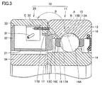
図3に示されるように、外輪13にはグリースポケット18が形成されておらず、凹部17の一端17Aは第1軌道面13Aに隣接する肩部13C上に形成されていてもよい。このようにしても、エアカーテンの影響を受けることなく、凹部17から上記第1空間部分を経て第1軌道面13Aに潤滑油を効率的に供給することができる。その結果、該軸受装置10は、上記径方向において潤滑油が保持器の外径面よりも内側に供給される軸受装置と比べて、長寿命である。
図4に示されるように、凹部17は、孔軸Bが屈曲するように形成されていてもよい。例えば、上記周方向に垂直な断面において、凹部17はL字状に形成されていてもよい。凹部17は、一端17Aを有し、かつその孔軸が上記径方向に沿って延び部分と、他端17Bを有し、かつその孔軸が上記軸方向に沿って延びる部分とで構成されていてもよい。また、上記周方向に垂直な断面において、凹部17は、U字状に形成されていてもよい。この場合、凹部17の他端17Bは、外輪13の幅面上に形成されていなくてもよい。他端17Bは、例えば外輪13の内周面上において保持器16の端面16Eよりも上記軸方向の外側に形成されていてもよい。吐出チューブ32は、吐出口32Aが他端17Bに接続されるように、形成されていればよい。
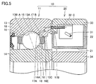
図5に示されるように、凹部17の一端17Aは、上記軸方向において転走跡13Bよりも上記接触角が生じない側(正面側)に位置する第1軌道面13A上に形成されていてもよい。このようにしても、潤滑油は、エアカーテンの影響を受けることなく、凹部17から上記第1空間部分を経て第1軌道面13Aに効率的に供給され得る。また、一端17Aが第1軌道面13A上であっても転走跡13B以外の領域に形成されているため、該軸受装置10では凹部17に起因した損傷が防止されている。なお、この場合、凹部17の他端17Bは、軸方向において正面側に位置する外輪13の端面上に形成されていてもよい。このようにすれば、上記軸方向において一端17Aと他端17Bとが接触角線Aを挟むように形成されている場合と比べて、凹部17の他端17Bから一端17Aまでの延在距離を短くすることができる。そのため、該軸受装置10は、凹部17から第1軌道面13Aに潤滑油を速やかに供給することができる。
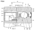
図6に示されるように、上記軸受装置10のアンギュラ玉軸受11は、固定輪としての内輪14と回転輪としての外輪13とを備えていてもよい。この場合、固定輪としての内輪14には、凹部17が形成されている。このような軸受11では、外輪13および保持器16の高速回転時に、固定輪としての内輪14に面する保持器16の内径面よりも上記径方向において外側に位置し、かつ上記軸方向において保持器16の端面16Eよりも外側にエアカーテンが生じ得る。これに対し、上記空間において固定輪としての内輪14に面する保持器16の内径面よりも上記径方向において内側に位置する第3空間部分には、少なくとも上記軸方向への潤滑油の流通を阻害し得るほどのエアカーテンが生じない。そのため、潤滑油が内輪14に形成された凹部17の一端17Aを介して上記第3空間部分に供給される軸受装置10によれば、エアカーテンによって潤滑油の供給が阻害されることが防止されている。上記第3空間部分に供給された潤滑油は、上記第3空間部分に接続されている第1軌道面13Aに濡れ広がることができる。その結果、軸受装置10は、上記径方向において潤滑油が回転輪としての外輪13と保持器16との間に供給される軸受装置よりも長寿命である。なお、図3~図6は、図2と同様に軸受装置10の周方向に垂直な断面を示す。
(実施の形態2)
図7および図8を参照して、実施の形態2に係る軸受装置110について説明する。軸受装置110は、基本的に実施の形態1に係る軸受装置10と同様の構成を備えるが、ノズルとしての吐出チューブ32の吐出口32Aが軸受11内に配置されている点で異なる。軸受装置110の潤滑油供給ユニット120は、基本的には実施の形態1に係る潤滑油供給ユニット20と同様の構成を備えるが、吐出チューブ32の吐出口32Aが軸受11の上記空間内に配置されている点で異なる。なお、図7は軸受装置110の周方向に垂直な断面を示す。
図7および図8を参照して、実施の形態2に係る軸受装置110について説明する。軸受装置110は、基本的に実施の形態1に係る軸受装置10と同様の構成を備えるが、ノズルとしての吐出チューブ32の吐出口32Aが軸受11内に配置されている点で異なる。軸受装置110の潤滑油供給ユニット120は、基本的には実施の形態1に係る潤滑油供給ユニット20と同様の構成を備えるが、吐出チューブ32の吐出口32Aが軸受11の上記空間内に配置されている点で異なる。なお、図7は軸受装置110の周方向に垂直な断面を示す。
すなわち、上記軸受装置110は、図7および図8に示されるように、アンギュラ玉軸受11と、外輪間座33と、内輪間座34と、上記供給部とを備える。アンギュラ玉軸受11は、第1軌道面13Aを有する固定輪としての外輪13と、外輪13の径方向において第1軌道面13Aと間隔を隔てて配置されている第2軌道面14Aを有する回転輪としての内輪14と、第1軌道面13Aと第2軌道面14Aとの間に接触角を持って配置される複数の玉15と、複数の玉15を保持する保持器16とを含む。外輪間座33は、アンギュラ玉軸受11の軸方向において外輪13に隣接している。内輪間座34は、上記軸方向において内輪14に隣接して、かつ上記径方向において外輪間座33と間隔を隔てて配置されている。上記供給部は、外輪間座33と内輪間座34との間に配置されている。上記供給部は、保持器16と外輪13との間に挟まれている隙間、すなわち上記第1空間部分に潤滑油を供給する。上記供給部は、上記隙間内に配置されており潤滑油を吐出する吐出口32Aを有するノズルとしての吐出チューブ32を含む。つまり、吐出口32Aは、上記軸方向における保持器16の端面16Eよりも内側に形成されている。
図7および図8に示されるように、上記軸受装置110における外輪13には、吐出チューブ32の一部が挿入されるノズル挿入用凹部117が形成されている。ノズル挿入用凹部117は、上記軸受装置10における凹部17と基本的に同様の構成を備え、吐出チューブ32の一部が挿入される点で異なっている。ノズル挿入用凹部117の上記軸方向の一端117Aは、外輪13と保持器16との間に挟まれている隙間、すなわち上記第1空間部分の上記微小空間部分に面している。上記ノズル挿入用凹部117の上記軸方向の他端117Bは、上記軸方向において一端117Aよりも外側に位置している。ノズル挿入用凹部117の他端117Bは、例えば上記軸方向において一端117Aよりも外側に位置する肩部13Cの端面上に形成されている。ノズル挿入用凹部117は、貫通孔として外輪13の肩部13Cに形成されている。ノズル挿入用凹部117の孔軸は、例えば上記軸方向に沿っている。ノズル挿入用凹部117の孔径は、吐出チューブ32の外径よりも長い。
図7および図8に示されるように、外輪13には、上記軸方向において接触角が生じる側で第1軌道面13Aと隣接し、かつ外輪13の周方向に沿うように溝部としてのグリースポケット18が形成されている。吐出口32Aは、グリースポケット18内に配置されている。
図7および図8に示されるように、軸受11は、固定輪としての外輪13と、回転輪としての内輪14とを備えている。
図7および図8に示されるように、吐出チューブ32の中心軸Cは、ノズル挿入用凹部117の孔軸に沿っており、例えば上記軸方向に沿っている。吐出チューブ32の吐出口32Aは、例えばノズル挿入用凹部117の他端117Bよりも一端117Aに近い位置に配置されている。つまり、吐出口32Aは、保持器16の端面16Eよりも第1軌道面13Aに近い位置に形成されている。吐出口32Aの保持器16側に位置する一部は、例えばグリースポケット18内に突出している。つまり、吐出口32Aは、上記第1空間部分の上記微小空間部分内に配置されている。
そのため、軸受装置110によれば、吐出口32Aから吐出された潤滑油は、エアカーテンの影響を受けることなく、グリースポケット18内から第1軌道面13Aに供給され得る。そのため、軸受装置110は、軸受装置10と同様の効果を奏することができる。
図7に示されるように、軸受装置110では、吐出口32Aの中心と軸受11の中心との間の径方向における距離L1、保持器16の外径の1/2(半分)であるL2、外輪13の第1軌道面13Aの溝底径の1/2(半分)であるL3、吐出口32Aの外径の1/2(半分)であるr、および外輪13と保持器16の外径面との間の上記径方向における距離L4が、L2+r+L4<L1<L3の関係を満足する。距離L1は、軸受11の中心軸を中心とし吐出口32Aの中心を通る円の半径に相当する。距離L4は、外輪13の肩部13Cの内周面と保持器16の外径面との間の上記径方向における距離に相当する。上記関係を満足するように吐出口32Aが配置されることにより、上記関係を満足するように吐出口32Aが配置されない場合と比べて、吐出口32Aと第1軌道面13Aとの間の上記径方向における最大距離、すなわち上記距離L1と上記距離L3との差は、短くなる。そのため、吐出口32Aから吐出された潤滑油は、上記第1空間部分を経て第1軌道面13Aにより効果的に供給され得る。
(実施の形態3)
次に、図9および図10を参照して、実施の形態3に係る軸受装置210について説明する。軸受装置210は、基本的に実施の形態2に係る軸受装置110と同様の構成を備えるが、ノズル挿入用凹部117が貫通孔ではなく溝として形成されている点で異なる。ノズル挿入用凹部117は固定輪としての外輪13において回転輪としての内輪14と対向する内周面上に溝として形成されている。なお、図9は軸受装置210の周方向に垂直な断面を示す。
次に、図9および図10を参照して、実施の形態3に係る軸受装置210について説明する。軸受装置210は、基本的に実施の形態2に係る軸受装置110と同様の構成を備えるが、ノズル挿入用凹部117が貫通孔ではなく溝として形成されている点で異なる。ノズル挿入用凹部117は固定輪としての外輪13において回転輪としての内輪14と対向する内周面上に溝として形成されている。なお、図9は軸受装置210の周方向に垂直な断面を示す。
図9および図10に示されるように、ノズル挿入用凹部117は、外輪13の肩部13Cの内周面に対して凹状に形成されている溝である。ノズル挿入用凹部117は、上記軸方向に沿って延びるように形成されている。上記軸方向に垂直な断面において、ノズル挿入用凹部117の内面は例えば半円弧を成している。ノズル挿入用凹部117の一端117Aは、グリースポケット18内に形成されている。つまり、一端117Aは、保持器16の端面16Eよりも第1軌道面13Aに近い位置に形成されており、上記第1空間部分の上記微小空間部分に面している。ノズル挿入用凹部117は、グリースポケット18に接続されている。ノズル挿入用凹部117の他端17Bは、例えば上記軸方向において一端117Aよりも外側に位置する肩部13Cの端面上に形成されている。ノズル挿入用凹部117の孔軸は、例えば上記軸方向に沿っている。ノズル挿入用凹部117は、吐出チューブ32の少なくとも一部を収容可能に設けられている。例えば、ノズル挿入用凹部117は、吐出チューブ32の吐出口32Aを含みかつ上記径方向において外輪13側に位置する一部を収容可能に設けられている。
図9および図10に示されるように、吐出チューブ32の中心軸Cは、ノズル挿入用凹部117の孔軸に沿っており、例えば上記軸方向に沿っている。吐出チューブ32の吐出口32Aは、例えばノズル挿入用凹部117の他端117Bよりも一端117Aに近い位置に配置されている。吐出口32Aの保持器16側に位置する一部は、例えばグリースポケット18内に突出している。つまり、吐出口32Aは、上記第1空間部分の上記微小空間部分内に配置されている。
そのため、軸受装置110によれば、吐出口32Aから吐出された潤滑油は、エアカーテンの影響を受けることなく、転走跡13Bを含む第1軌道面13Aに供給され得る。そのため、軸受装置210は、軸受装置10,110と同様の効果を奏することができる。
<変形例>
軸受装置110,210は、上述した軸受装置10の変形例と同様に変形され得る。例えば、軸受装置110,210において、ノズル挿入用凹部117の一端117Aは、グリースポケット18内に形成されていなくてもよい。ノズル挿入用凹部117の一端117Aは、上記軸方向において任意の位置に形成されていてもよい。例えば、ノズル挿入用凹部117の上記一端117Aは、上記軸方向において保持器16の端面16Eよりも外側に形成されていてもよい。外輪13にはグリースポケット18が形成されておらず、ノズル挿入用凹部117の一端117Aは第1軌道面13Aに隣接する肩部13C上に形成されていてもよい。ノズル挿入用凹部117の一端117Aは、上記軸方向において転走跡13Bよりも上記接触角が生じない側(正面側)に位置する第1軌道面13A上に形成されていてもよい。ノズル挿入用凹部117の孔軸は、上記軸方向に対して傾斜するように形成されていてもよい。
軸受装置110,210は、上述した軸受装置10の変形例と同様に変形され得る。例えば、軸受装置110,210において、ノズル挿入用凹部117の一端117Aは、グリースポケット18内に形成されていなくてもよい。ノズル挿入用凹部117の一端117Aは、上記軸方向において任意の位置に形成されていてもよい。例えば、ノズル挿入用凹部117の上記一端117Aは、上記軸方向において保持器16の端面16Eよりも外側に形成されていてもよい。外輪13にはグリースポケット18が形成されておらず、ノズル挿入用凹部117の一端117Aは第1軌道面13Aに隣接する肩部13C上に形成されていてもよい。ノズル挿入用凹部117の一端117Aは、上記軸方向において転走跡13Bよりも上記接触角が生じない側(正面側)に位置する第1軌道面13A上に形成されていてもよい。ノズル挿入用凹部117の孔軸は、上記軸方向に対して傾斜するように形成されていてもよい。
以上のように本発明の実施の形態について説明を行ったが、上述の実施の形態を様々に変形することも可能である。また、本発明の範囲は上述の実施の形態に限定されるものではない。本発明の範囲は、請求の範囲によって示され、請求の範囲と均等の意味および範囲内でのすべての変更を含むことが意図される。
本発明は、回転輪が高速回転されるアンギュラ玉軸受を備える軸受装置に特に有利に適用される。
10,110,210 軸受装置、11 アンギュラ玉軸受、13 外輪、13A 第1軌道面、13B 転走跡、13C 肩部、14 内輪、14A 第2軌道面、15 玉、16 保持器、16E 端面、17 凹部、17A 一端、17B 他端、18 グリースポケット、20,120 潤滑油供給ユニット、21 ハウジング本体、22 蓋体、23a,23b 熱伝導体、24 熱電素子、25 発電部、26 電源回路、27 制御回路、28 駆動回路、29 ポンプ、30 潤滑油タンク、31 吸込みチューブ、32 吐出チューブ、32A 吐出口、33 外輪間座、34 内輪間座、35 タップ穴、36 隙間、117 ノズル挿入用凹部、117A 一端、117B 他端。
Claims (8)
- 第1軌道面を有する固定輪と、前記固定輪の径方向において前記第1軌道面と間隔を隔てて配置されている第2軌道面を有する回転輪と、前記第1軌道面と前記第2軌道面との間に接触角を持って配置される複数の転動体と、前記複数の転動体を保持する保持器とを含むアンギュラ玉軸受と、
前記アンギュラ玉軸受の軸方向において前記固定輪に隣接している固定輪間座と、
前記軸方向において前記回転輪に隣接して、かつ前記径方向において前記固定輪間座と間隔を隔てて配置されている回転輪間座と、
前記固定輪間座と前記回転輪間座との間に配置されており、前記保持器と前記固定輪との間に挟まれている隙間に潤滑油を供給する供給部とを備え、
前記供給部は、前記隙間内に配置されており前記潤滑油を吐出する吐出口を有するノズルを含む、軸受装置。 - 前記固定輪には、前記ノズルの一部が挿入されるノズル挿入用凹部が形成されており、
前記ノズル挿入用凹部は少なくとも前記軸方向に延びており、
前記ノズル挿入用凹部の前記軸方向の一端は、前記隙間に面しており、
前記ノズル挿入用凹部の前記軸方向の他端は、前記軸方向において前記一端よりも外側に位置しており、
前記ノズルの一部は、前記ノズル挿入用凹部内に配置されている、請求項1に記載の軸受装置。 - 前記ノズル挿入用凹部は貫通孔として形成されている、請求項2に記載の軸受装置。
- 前記ノズル挿入用凹部は前記固定輪において前記回転輪と対向する周面上に溝として形成されている、請求項2に記載の軸受装置。
- 前記固定輪には、前記軸方向において前記接触角が生じる側で前記第1軌道面と隣接し、かつ前記固定輪の周方向に沿うように溝部が形成されており、
前記吐出口は、前記溝部内に配置されている、請求項1~4のいずれか1項に記載の軸受装置。 - 前記固定輪が外輪であり、前記回転輪が内輪である、請求項1~5のいずれか1項に記載の軸受装置。
- 前記吐出口の中心と前記アンギュラ玉軸受の中心との間の前記径方向における距離L1、前記保持器の外径の半分L2、前記固定輪の前記第1軌道面の溝底径の半分L3、前記吐出口の外径の半分r、および前記固定輪と前記保持器の外径面との間の前記径方向における距離L4が、L2+r+L4<L1<L3の関係を満足する、請求項6に記載の軸受装置。
- 前記供給部を作動させるための電力を発生させる発電部をさらに備え、
前記発電部は、前記固定輪間座と前記回転輪間座との間に配置されている、請求項1~7のいずれか1項に記載の軸受装置。
Priority Applications (3)
| Application Number | Priority Date | Filing Date | Title |
|---|---|---|---|
| KR1020197016027A KR102477895B1 (ko) | 2016-11-10 | 2017-10-26 | 베어링 장치 |
| EP17870355.9A EP3540253B1 (en) | 2016-11-10 | 2017-10-26 | Bearing apparatus |
| CN201780069431.5A CN109937309B (zh) | 2016-11-10 | 2017-10-26 | 轴承装置 |
Applications Claiming Priority (2)
| Application Number | Priority Date | Filing Date | Title |
|---|---|---|---|
| JP2016-219570 | 2016-11-10 | ||
| JP2016219570A JP6906294B2 (ja) | 2016-11-10 | 2016-11-10 | 軸受装置 |
Publications (1)
| Publication Number | Publication Date |
|---|---|
| WO2018088227A1 true WO2018088227A1 (ja) | 2018-05-17 |
Family
ID=62109271
Family Applications (1)
| Application Number | Title | Priority Date | Filing Date |
|---|---|---|---|
| PCT/JP2017/038742 WO2018088227A1 (ja) | 2016-11-10 | 2017-10-26 | 軸受装置 |
Country Status (5)
| Country | Link |
|---|---|
| EP (1) | EP3540253B1 (ja) |
| JP (1) | JP6906294B2 (ja) |
| KR (1) | KR102477895B1 (ja) |
| CN (1) | CN109937309B (ja) |
| WO (1) | WO2018088227A1 (ja) |
Cited By (3)
| Publication number | Priority date | Publication date | Assignee | Title |
|---|---|---|---|---|
| WO2020189188A1 (ja) * | 2019-03-19 | 2020-09-24 | Ntn株式会社 | 潤滑油供給ユニットおよび軸受装置 |
| CN113613815A (zh) * | 2019-03-19 | 2021-11-05 | Ntn株式会社 | 润滑油供应单元和轴承装置 |
| US20220373036A1 (en) * | 2019-09-26 | 2022-11-24 | Ntn Corporation | Bearing apparatus and spacer |
Citations (4)
| Publication number | Priority date | Publication date | Assignee | Title |
|---|---|---|---|---|
| JP2011106493A (ja) * | 2009-11-13 | 2011-06-02 | Ntn Corp | 転がり軸受装置 |
| JP2014031810A (ja) * | 2012-08-01 | 2014-02-20 | Ntn Corp | 転がり軸受装置 |
| JP2014037879A (ja) | 2012-08-20 | 2014-02-27 | Ntn Corp | 転がり軸受装置 |
| JP2016023757A (ja) * | 2014-07-23 | 2016-02-08 | 株式会社ジェイテクト | 転がり軸受装置及び給油ユニット |
Family Cites Families (6)
| Publication number | Priority date | Publication date | Assignee | Title |
|---|---|---|---|---|
| JP2008286270A (ja) * | 2007-05-16 | 2008-11-27 | Ntn Corp | ころ軸受の潤滑装置 |
| JP2009097553A (ja) * | 2007-10-15 | 2009-05-07 | Ntn Corp | 転がり軸受 |
| JP5233561B2 (ja) * | 2008-10-03 | 2013-07-10 | 株式会社ジェイテクト | 転がり軸受 |
| JP2010091067A (ja) * | 2008-10-10 | 2010-04-22 | Ntn Corp | アンギュラ玉軸受の潤滑構造 |
| JP2013076428A (ja) * | 2011-09-29 | 2013-04-25 | Ntn Corp | 軸受装置 |
| JP6446887B2 (ja) * | 2014-07-23 | 2019-01-09 | 株式会社ジェイテクト | 転がり軸受装置及び給油ユニット |
-
2016
- 2016-11-10 JP JP2016219570A patent/JP6906294B2/ja active Active
-
2017
- 2017-10-26 KR KR1020197016027A patent/KR102477895B1/ko active IP Right Grant
- 2017-10-26 EP EP17870355.9A patent/EP3540253B1/en active Active
- 2017-10-26 WO PCT/JP2017/038742 patent/WO2018088227A1/ja unknown
- 2017-10-26 CN CN201780069431.5A patent/CN109937309B/zh active Active
Patent Citations (4)
| Publication number | Priority date | Publication date | Assignee | Title |
|---|---|---|---|---|
| JP2011106493A (ja) * | 2009-11-13 | 2011-06-02 | Ntn Corp | 転がり軸受装置 |
| JP2014031810A (ja) * | 2012-08-01 | 2014-02-20 | Ntn Corp | 転がり軸受装置 |
| JP2014037879A (ja) | 2012-08-20 | 2014-02-27 | Ntn Corp | 転がり軸受装置 |
| JP2016023757A (ja) * | 2014-07-23 | 2016-02-08 | 株式会社ジェイテクト | 転がり軸受装置及び給油ユニット |
Non-Patent Citations (1)
| Title |
|---|
| See also references of EP3540253A4 |
Cited By (6)
| Publication number | Priority date | Publication date | Assignee | Title |
|---|---|---|---|---|
| WO2020189188A1 (ja) * | 2019-03-19 | 2020-09-24 | Ntn株式会社 | 潤滑油供給ユニットおよび軸受装置 |
| CN113613815A (zh) * | 2019-03-19 | 2021-11-05 | Ntn株式会社 | 润滑油供应单元和轴承装置 |
| EP3943221A4 (en) * | 2019-03-19 | 2022-11-30 | NTN Corporation | LUBRICATION OIL FEED UNIT AND BEARING DEVICE |
| JP7411347B2 (ja) | 2019-03-19 | 2024-01-11 | Ntn株式会社 | 潤滑油供給ユニットおよび軸受装置 |
| US20220373036A1 (en) * | 2019-09-26 | 2022-11-24 | Ntn Corporation | Bearing apparatus and spacer |
| US11940010B2 (en) * | 2019-09-26 | 2024-03-26 | Ntn Corporation | Bearing apparatus and spacer |
Also Published As
| Publication number | Publication date |
|---|---|
| JP2018076925A (ja) | 2018-05-17 |
| EP3540253A4 (en) | 2020-06-17 |
| JP6906294B2 (ja) | 2021-07-21 |
| CN109937309A (zh) | 2019-06-25 |
| EP3540253B1 (en) | 2022-01-19 |
| KR20190071819A (ko) | 2019-06-24 |
| KR102477895B1 (ko) | 2022-12-15 |
| EP3540253A1 (en) | 2019-09-18 |
| CN109937309B (zh) | 2021-11-12 |
Similar Documents
| Publication | Publication Date | Title |
|---|---|---|
| JP6136279B2 (ja) | 転がり軸受装置 | |
| WO2018088227A1 (ja) | 軸受装置 | |
| JP2008008411A (ja) | 冠型保持器、及び該冠型保持器を用いた転がり軸受 | |
| JP2016023757A (ja) | 転がり軸受装置及び給油ユニット | |
| JP2016516969A (ja) | グリース潤滑式のアンギュラ玉軸受 | |
| JP6339433B2 (ja) | モータ内蔵スピンドル用玉軸受 | |
| WO2018088226A1 (ja) | 軸受装置 | |
| KR102599685B1 (ko) | 베어링 장치 | |
| JP2011163465A (ja) | 軸受装置及び工作機械用主軸装置 | |
| JP4692385B2 (ja) | 転がり軸受装置 | |
| JP6414656B2 (ja) | 転がり軸受装置および転がり軸受装置の製造方法 | |
| KR102657631B1 (ko) | 베어링 장치 및 기계 장치 | |
| JP6560029B2 (ja) | モータ内蔵スピンドル用玉軸受 | |
| KR102655632B1 (ko) | 베어링 장치 및 기계 장치 | |
| JP2008240826A (ja) | 玉軸受および保持器 | |
| JP5908732B2 (ja) | 転がり軸受装置 | |
| KR102091916B1 (ko) | 냉각액 배출장치, 볼나사장치 | |
| JP2017058004A (ja) | ボールねじ | |
| JP2017031984A (ja) | 転がり軸受 | |
| JP6414663B2 (ja) | 転がり軸受装置 | |
| JP6460368B2 (ja) | 転がり軸受装置 | |
| JP2005024078A (ja) | 遊星ローラ式動力伝達装置 | |
| JP2009204139A (ja) | 転がり軸受、およびそれを用いた主軸装置 | |
| JP2016161085A (ja) | アンギュラ玉軸受 | |
| JP2007285502A (ja) | 玉軸受 |
Legal Events
| Date | Code | Title | Description |
|---|---|---|---|
| 121 | Ep: the epo has been informed by wipo that ep was designated in this application |
Ref document number: 17870355 Country of ref document: EP Kind code of ref document: A1 |
|
| NENP | Non-entry into the national phase |
Ref country code: DE |
|
| ENP | Entry into the national phase |
Ref document number: 20197016027 Country of ref document: KR Kind code of ref document: A |
|
| ENP | Entry into the national phase |
Ref document number: 2017870355 Country of ref document: EP Effective date: 20190611 |