WO2018079433A1 - 積層体の製造方法 - Google Patents
積層体の製造方法 Download PDFInfo
- Publication number
- WO2018079433A1 WO2018079433A1 PCT/JP2017/038003 JP2017038003W WO2018079433A1 WO 2018079433 A1 WO2018079433 A1 WO 2018079433A1 JP 2017038003 W JP2017038003 W JP 2017038003W WO 2018079433 A1 WO2018079433 A1 WO 2018079433A1
- Authority
- WO
- WIPO (PCT)
- Prior art keywords
- resin composition
- photocurable resin
- light
- resin layer
- light irradiation
- Prior art date
- Legal status (The legal status is an assumption and is not a legal conclusion. Google has not performed a legal analysis and makes no representation as to the accuracy of the status listed.)
- Ceased
Links
Images





Classifications
-
- B—PERFORMING OPERATIONS; TRANSPORTING
- B05—SPRAYING OR ATOMISING IN GENERAL; APPLYING FLUENT MATERIALS TO SURFACES, IN GENERAL
- B05D—PROCESSES FOR APPLYING FLUENT MATERIALS TO SURFACES, IN GENERAL
- B05D3/00—Pretreatment of surfaces to which liquids or other fluent materials are to be applied; After-treatment of applied coatings, e.g. intermediate treating of an applied coating preparatory to subsequent applications of liquids or other fluent materials
- B05D3/06—Pretreatment of surfaces to which liquids or other fluent materials are to be applied; After-treatment of applied coatings, e.g. intermediate treating of an applied coating preparatory to subsequent applications of liquids or other fluent materials by exposure to radiation
-
- B—PERFORMING OPERATIONS; TRANSPORTING
- B05—SPRAYING OR ATOMISING IN GENERAL; APPLYING FLUENT MATERIALS TO SURFACES, IN GENERAL
- B05D—PROCESSES FOR APPLYING FLUENT MATERIALS TO SURFACES, IN GENERAL
- B05D7/00—Processes, other than flocking, specially adapted for applying liquids or other fluent materials to particular surfaces or for applying particular liquids or other fluent materials
- B05D7/24—Processes, other than flocking, specially adapted for applying liquids or other fluent materials to particular surfaces or for applying particular liquids or other fluent materials for applying particular liquids or other fluent materials
-
- B—PERFORMING OPERATIONS; TRANSPORTING
- B29—WORKING OF PLASTICS; WORKING OF SUBSTANCES IN A PLASTIC STATE IN GENERAL
- B29C—SHAPING OR JOINING OF PLASTICS; SHAPING OF MATERIAL IN A PLASTIC STATE, NOT OTHERWISE PROVIDED FOR; AFTER-TREATMENT OF THE SHAPED PRODUCTS, e.g. REPAIRING
- B29C65/00—Joining or sealing of preformed parts, e.g. welding of plastics materials; Apparatus therefor
- B29C65/48—Joining or sealing of preformed parts, e.g. welding of plastics materials; Apparatus therefor using adhesives, i.e. using supplementary joining material; solvent bonding
- B29C65/52—Joining or sealing of preformed parts, e.g. welding of plastics materials; Apparatus therefor using adhesives, i.e. using supplementary joining material; solvent bonding characterised by the way of applying the adhesive
- B29C65/54—Joining or sealing of preformed parts, e.g. welding of plastics materials; Apparatus therefor using adhesives, i.e. using supplementary joining material; solvent bonding characterised by the way of applying the adhesive between pre-assembled parts
-
- G—PHYSICS
- G02—OPTICS
- G02F—OPTICAL DEVICES OR ARRANGEMENTS FOR THE CONTROL OF LIGHT BY MODIFICATION OF THE OPTICAL PROPERTIES OF THE MEDIA OF THE ELEMENTS INVOLVED THEREIN; NON-LINEAR OPTICS; FREQUENCY-CHANGING OF LIGHT; OPTICAL LOGIC ELEMENTS; OPTICAL ANALOGUE/DIGITAL CONVERTERS
- G02F1/00—Devices or arrangements for the control of the intensity, colour, phase, polarisation or direction of light arriving from an independent light source, e.g. switching, gating or modulating; Non-linear optics
- G02F1/01—Devices or arrangements for the control of the intensity, colour, phase, polarisation or direction of light arriving from an independent light source, e.g. switching, gating or modulating; Non-linear optics for the control of the intensity, phase, polarisation or colour
- G02F1/13—Devices or arrangements for the control of the intensity, colour, phase, polarisation or direction of light arriving from an independent light source, e.g. switching, gating or modulating; Non-linear optics for the control of the intensity, phase, polarisation or colour based on liquid crystals, e.g. single liquid crystal display cells
- G02F1/133—Constructional arrangements; Operation of liquid crystal cells; Circuit arrangements
- G02F1/1333—Constructional arrangements; Manufacturing methods
-
- G—PHYSICS
- G09—EDUCATION; CRYPTOGRAPHY; DISPLAY; ADVERTISING; SEALS
- G09F—DISPLAYING; ADVERTISING; SIGNS; LABELS OR NAME-PLATES; SEALS
- G09F9/00—Indicating arrangements for variable information in which the information is built-up on a support by selection or combination of individual elements
Definitions
- An image display device used for information terminals such as smartphones and tablet PCs is manufactured, for example, by the following method (for example, see Patent Document 1).
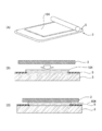
- a liquid photocurable resin composition is formed on the surface of a light transmissive member (first member) 3 having a light shielding layer 5 formed on the peripheral portion from a nozzle 101 ⁇ / b> A of the application unit 101. 6 is applied.
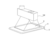
- the photocurable resin composition 6 applied to the surface of the light transmissive member 3 is irradiated with light from the light irradiation unit 102 to form a temporarily cured resin layer 103.
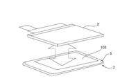
- the light transmissive member 3 and the image display member (second member) 2 are bonded via a temporarily cured resin layer 103.
- the temporarily-cured resin layer 103 is irradiated with light to fully cure the temporarily-cured resin layer 103 to form a cured resin layer. Thereby, an image display apparatus is obtained.
- a method of pasting the applied photocurable resin composition without pre-curing it may be mentioned.
- a photocurable resin composition 6 is applied to the surface of the light transmissive member 3, and light transmissive properties are obtained as shown in FIGS. 12 (B) and 12 (C).
- the member 3 and the image display member 2 are bonded together via the photocurable resin composition 6. Then, the photocurable resin composition 6 is fully cured.
- an optical pressure-sensitive adhesive sheet OCA: “Optical” Clear—Adhesive
- OCA optical pressure-sensitive adhesive sheet
- the photocurable resin composition 6 is applied to the surface of the light transmissive member 3 as shown in FIG.
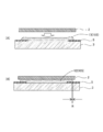
- dripping tends to occur at the edge of the applied photocurable resin composition.
- This liquid dripping causes the non-bonded region R as shown in FIG. 14B to be generated when the light transmissive member 3 and the image display member 2 are bonded together via the temporarily cured resin layer 103.
- the non-bonded region R is generated, for example, it is difficult to earn a bonded region in a liquid crystal display panel having a narrow frame. Note that, as shown in FIGS.
- the photocurable resin composition can be bonded in a liquid state without being temporarily cured, or as shown in FIGS. 13A to 13C.
- the method using the pressure-sensitive adhesive sheet 104 it is considered that liquid dripping hardly occurs and the problem of the non-bonded region R is small.
- the present technology has been proposed in view of such a conventional situation, and provides a method for manufacturing a laminate that can suppress dripping when a photocurable resin composition is applied.
- the manufacturing method of the laminated body which concerns on this technique WHEREIN: The process (A) of forming the temporary hardening resin layer which hardened the photocurable resin composition on the surface of the 1st member, the 1st member, 2nd The step (B) of pasting the members of the temporary curing resin layer through the temporarily cured resin layer and the step (C) of permanently irradiating the temporarily cured resin layer with light irradiation, the step (A) includes the first step A step (A1) of applying a photocurable resin composition to the surface of the member and irradiating the photocurable resin composition with light in order to prevent deformation of the applied photocurable resin composition; and a step (A1). (A2) which further irradiates with light so that the photocurable resin composition irradiated with light may become a predetermined reaction rate.
- the step of forming the temporarily cured resin layer includes irradiating the photocurable resin composition with light to prevent deformation of the applied photocurable resin composition.
- coating a composition can be suppressed.
- FIG. 1 is a cross-sectional view showing an example of a laminate obtained by the laminate production method.
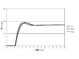
- FIG. 2 is a graph showing measurement results of the height of the application surface of the photocurable resin composition according to the elapsed time from application of the photocurable resin composition to light irradiation.
- FIG. 3 is a graph showing measurement results of the height of the application surface of the photocurable resin composition according to the application thickness of the photocurable resin composition.
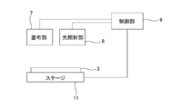
- FIG. 4 is a block diagram illustrating a configuration example of the coating apparatus.
- Drawing 5 is a figure for explaining an example of a process (A1) in a manufacturing method of a layered product.
- Drawing 6 is a figure for explaining an example of a process (A2) in a manufacturing method of a layered product.
- FIG. 1 is a cross-sectional view showing an example of a laminate obtained by the laminate production method.
- FIG. 2 is a graph showing measurement results of the height of the application surface of the photocurable resin composition according to the
- FIG. 7 is a graph showing changes in the amount of dripping with respect to the coating thickness of the photocurable resin composition and the time from application of the photocurable resin composition to light irradiation.
- FIG. 8 is a graph showing a change in the amount of dripping due to the difference in viscosity of the photocurable resin composition.
- FIG. 9 is a perspective view showing an example of a step of applying a photocurable resin composition to the surface of the light transmissive member.
- FIG. 10 is a perspective view showing an example of a step of forming a temporarily cured resin layer by irradiating light to the photocurable resin composition.
- FIG. 11 is a perspective view showing an example of a step of bonding the light transmissive member and the image display member through a temporarily cured resin layer.
- FIG. 12 is a diagram for explaining an example of a method for manufacturing an image display device.
- FIG. 12A is a perspective view showing an example of a process of applying a photocurable resin composition to the surface of a light transmissive member.
- FIGS. 12B and 12C are cross-sectional views illustrating an example of a process of bonding the light transmissive member and the image display member via the photocurable resin composition.
- FIG. 13 is a diagram for explaining an example of a method for manufacturing an image display device, and FIG.
- FIG. 13A is a perspective view illustrating an example of a process of attaching an optically transparent adhesive sheet to the surface of a light transmissive member.
- FIG. 13B and FIG. 13C are cross-sectional views showing an example of a process of bonding the light transmissive member and the image display member through the optical transparent adhesive sheet.
- FIG. 14 is a cross-sectional view showing an example of a process of bonding a light transmissive member and an image display member through a temporarily cured resin layer
- FIG. 14A is a cross-sectional view for explaining an example of liquid dripping.
- FIG. 14B is a cross-sectional view for explaining an example of the non-bonded region R.
- a light transmissive member 3 (first member) having a light shielding layer 5 formed on the peripheral edge portion and an image display member 2 (first member). 2) to obtain an image display device 1 (laminated body) laminated with the cured resin layer 4 interposed therebetween.
- the image display member 2 examples include a liquid crystal display panel, an organic EL display panel, a plasma display panel, and a touch panel.
- the touch panel means an image display / input panel in which a display element such as a liquid crystal display panel and a position input device such as a touch pad are combined.
- the light transmissive member 3 only needs to be light transmissive so that an image formed on the image display member 2 can be visually recognized. Examples thereof include plate-like materials and sheet-like materials such as glass, acrylic resin, polyethylene terephthalate, polyethylene naphthalate, and polycarbonate. These materials may be subjected to a hard coat treatment, an antireflection treatment or the like on at least one surface. Physical properties such as thickness and elastic modulus of the light transmissive member 3 can be appropriately determined according to the purpose of use.
- the light transmission member 3 includes not only a member having a relatively simple structure as described above but also a member in which various sheets or film materials such as a touch panel module are laminated.
- the light-shielding layer 5 is provided to improve the contrast of the image, and can be formed, for example, by applying a paint colored in black or the like by a screen printing method and drying and curing.
- the thickness of the light shielding layer 5 is usually 5 to 100 ⁇ m.
- the refractive index of the cured resin layer 4 is preferably substantially equal to the refractive index of the image display member 2 or the light transmissive member 3, and is preferably 1.45 or more and 1.55 or less, for example. Thereby, the brightness
- the thickness of the cured resin layer 4 is preferably 50 to 150 ⁇ m, for example.
- the cured resin layer 4 can be formed by using a liquid photocurable resin composition 6 that is transparent and can be cured with ultraviolet rays or visible light.
- the photocurable resin composition 6 may be in any state such as liquid or gel, and is preferably liquid.
- the photocurable resin composition 6 being in a liquid state preferably has a viscosity of 0.01 to 100 Pa ⁇ s at 25 ° C. as measured with a B-type viscometer.
- the photocurable resin composition is applied. Liquid dripping can be suppressed.
- the photocurable resin composition 6 contains, for example, a (meth) acrylate oligomer, a (meth) acrylate monomer, a photopolymerization initiator, and a softening agent.
- the photocurable resin composition 6 may further contain other components other than these components in the range which does not impair the effect of this technique.
- (meth) acrylate includes both acrylate and methacrylate.
- (Meth) acrylate oligomer is used as a base material for the photocurable resin composition 6.
- the (meth) acrylate oligomer for example, a (meth) acrylate oligomer having a skeleton of polyurethane, polyisoprene, polybutadiene, or the like can be used.
- Specific examples of the (meth) acrylate oligomer having a polyurethane skeleton include aliphatic urethane acrylate (EBECRYL230, manufactured by Daicel Ornex).
- the (meth) acrylate oligomer having a polyisoprene skeleton include an esterified product of a polyisoprene polymer maleic anhydride adduct and 2-hydroxyethyl methacrylate (UC102, manufactured by Kuraray Co., Ltd.). Can be mentioned.
- (Meth) acrylate monomer is used as a reaction diluent for imparting sufficient reactivity, coatability and the like to the photocurable resin composition 6.
- the (meth) acrylate monomer include 2-hydroxypropyl (meth) acrylate, benzyl acrylate, dicyclopentenyloxyethyl (meth) acrylate, isobornyl (meth) acrylate, octyl (meth) acrylate, and the like.
- photopolymerization initiator a known photopolymerization initiator can be used.
- 1-hydroxy-cyclohexyl phenyl ketone (Irgacure 184, manufactured by BASF)
- examples thereof include methyl-1-propan-1-one (Irgacure 127, manufactured by BASF), benzophenone, acetophenone, and the like.
- the softener comprises at least one of a liquid plasticizer and a tackifier.
- the liquid plasticizer itself is not photocured by ultraviolet irradiation, gives flexibility to the cured resin layer or the precured resin layer after photocuring, and reduces the cure shrinkage of the cured resin layer or the precured resin layer. It is something to be made.
- the liquid plasticizer include a polybutadiene plasticizer, a polyisoprene plasticizer, a phthalate ester plasticizer, and an adipate ester plasticizer.
- the tackifier imparts flexibility to the cured resin layer or the temporarily cured resin layer after photocuring, and improves the initial adhesive strength (so-called tackiness) of the cured resin layer or the temporarily cured resin layer.
- the tackifier include terpene resins such as terpene resins, terpene phenol resins, and hydrogenated terpene resins, rosin resins such as natural rosin, polymerized rosin, rosin ester, and hydrogenated rosin, and petroleum resins such as polybutadiene and polyisoprene. Etc.
- the photocurable resin composition can be prepared by uniformly mixing the above-described components according to a known mixing technique.
- Commercially available products of the photocurable resin composition include, for example, trade names “LCR1000-DM”, “HSVR600”, “HSVR330” (above, manufactured by Dexerials Corporation).
- This manufacturing method includes the following steps (A) to (C).
- a process (A) has the following processes (A1) and (A2).
- Step (A1) The photocurable resin composition is applied to the surface of the first member, and the photocurable resin composition is irradiated with light in order to prevent deformation of the applied photocurable resin composition.
- this manufacturing method prevents the deformation
- it includes irradiating light to a photocurable resin composition.
- coating a photocurable resin composition can be suppressed.
- dripping can be suppressed even when a photocurable resin composition having a relatively low viscosity is used.
- This manufacturing method is suitable, for example, when a liquid crystal display panel having a narrow frame (for example, a width of 1 mm or less) is used.
- FIG. 2 is a graph showing the measurement results of the height of the coated surface of the photocurable resin composition according to the elapsed time from application of the photocurable resin composition to light irradiation.
- FIG. 3 is a graph which shows the measurement result of the height of the application surface of a photocurable resin composition by the application thickness of a photocurable resin composition.
- shaft in FIG. 2, FIG. 3 represents application
- shaft in FIG. 2, FIG. 3 represents the distance (mm) from one edge part of the longitudinal direction of the light transmissive member to which a photocurable resin composition is apply
- the application thickness of the photocurable resin composition is measured using, for example, a known displacement sensor that measures the height by irradiating the application surface of the photocurable resin composition with laser, ultrasonic waves, or the like. be able to.
- the dripping becomes shorter as the elapsed time from the application of the photocurable resin composition to the surface of the light-transmitting member to the light irradiation becomes as short as 15 seconds, 10 seconds, and 5 seconds. It can be seen that there is a small tendency. Moreover, it can be seen from the results shown in FIG. 3 that the dripping tends to be suppressed as the coating thickness of the photocurable resin composition is reduced to 250 ⁇ m, 175 ⁇ m, and 100 ⁇ m.
- a light irradiation part for example, an ultraviolet irradiator
- a light irradiation part is disposed in the vicinity of the application part (nozzle) for applying the photocurable resin composition, and light irradiation is performed while applying the photocurable resin composition
- a method of performing (temporary curing) is ideal.
- this method is not always effective for all photocurable resin compositions.
- optimal temporary curing conditions may not be achieved unless the coating speed of the photocurable resin composition is extremely reduced.
- the optimum light irradiation amount varies depending on the type of the photocurable resin composition. This is because the pre-cured state affects the strength of the photocurable resin composition after the main curing, the presence or absence of unevenness, and the like.
- the step of forming the temporarily cured resin layer is performed at least twice.
- the photocurable resin composition is irradiated with light in order to prevent deformation of the photocurable resin composition. That is, it is temporarily cured to such an extent that the application shape of the photocurable resin composition can be maintained. Thereby, the dripping of the applied photocurable resin composition is suppressed.
- the second temporary curing step (A2)
- light irradiation is further performed so that the temporary cured resin layer obtained by the first temporary curing has a predetermined reaction rate.
- the temporarily-cured resin layer that has been temporarily cured to the extent that bonding can be performed while maintaining the coating shape of the photo-curable resin composition is obtained.
- the photocurable resin composition applied when the photocurable resin composition was applied without using an area-type light irradiator or a coating apparatus capable of high-speed and high-precision driving. It is possible to suppress the occurrence of liquid dripping at the end portion. Therefore, the dripping at the time of apply
- step (A1), step (A2), step (B), and step (C) will be described.
- Step (A1) Application
- a coating apparatus including a coating unit 7, a light irradiation unit 8, and a control unit 9 can be used.
- the application unit 7 includes, for example, a storage unit (not shown) that stores the photocurable resin composition 6, and a slit-like nozzle 7 ⁇ / b> A (see FIGS. 5 and 6) that discharges the photocurable resin composition 6. And a pump (not shown) for extruding the photocurable resin composition 6 stored in the storage unit to the nozzle 7A.
- the application unit 7 has a width of the nozzle 7 ⁇ / b> A wider than the width of the region 3 ⁇ / b> S surrounded by the light shielding layer 5 on the surface of the light transmissive member 3.
- the nozzle 7 ⁇ / b> A has a width that straddles each light shielding layer 5 formed at both ends in the width direction of the light transmissive member 3 and the region 3 ⁇ / b> S.
- the application part 7 can apply
- the light irradiation unit 8 is preferably arranged in the vicinity of the application unit 7 and at a position where the nozzle 7A of the application unit 7 is not irradiated with light. With this arrangement, it is possible to prevent the tip portion of the nozzle 7 ⁇ / b> A from being hardened by the cured product of the photocurable resin composition 6.
- an ultraviolet irradiator can be used as the light irradiation unit 8.
- the control unit 9 relatively moves the coating unit 7 and the light irradiation unit 8 and the light transmissive member 3. Thereby, while applying the photocurable resin composition 6 from one end side to the other end side of the surface of the light transmissive member 3, the applied photocurable resin composition 6 is irradiated with light.
- the stage on which the light transmissive member 3 is placed is moved in the direction of the arrow, and one end side of the surface of the light transmissive member 3 is placed. It is preferable to light-irradiate the applied photocurable resin composition 6 from the light irradiation unit 8 while applying the photocurable resin composition 6 from 3 ⁇ / b> A to the other end side 3 ⁇ / b> B from the application unit 7. Thereby, dripping at the time of apply
- the photocurable resin composition 6 is applied from one end side 3A to the other end side 3B of the surface of the light transmissive member 3 without moving the stage on which the light transmissive member 3 is placed. However, you may move the application part 7 and the light irradiation part 8 so that the applied photocurable resin composition 6 may be irradiated with light.
- the elapsed time from when the photocurable resin composition 6 is applied to the surface of the light transmitting member 3 until it is irradiated with light (hereinafter also referred to as “time from application to light irradiation”). From the viewpoint of suppressing dripping of the photocurable resin composition 6, the shorter the better. For example, the time from application to light irradiation is preferably within 5 seconds.
- the coating thickness of the photocurable resin composition 6 is preferably greater than the thickness of the light shielding layer 5 when the light shielding layer 5 is formed on the peripheral portion of the surface of the light transmissive member 3.
- the thickness of the light shielding layer 5 is 1.2 to 50 times (more preferably 2 to 30 times) the entire surface of the light transmissive member 3 including the surface of the light shielding layer 5 on the light shielding layer forming side surface. It is preferable to apply with a thickness of.
- a more specific coating thickness is preferably 25 to 350 ⁇ m, more preferably 50 to 150 ⁇ m.
- the light irradiation conditions in the step (A1) are preferably performed so that, for example, the curing rate of the temporarily cured resin layer 12 obtained after the light irradiation in the step (A1) is 40 to 50%.
- the curing rate is the ratio (consumption ratio) of the amount of (meth) acryloyl group after light irradiation to the amount of (meth) acryloyl group in the photocurable resin composition before light irradiation.
- the curing rate is determined by the absorption peak height (X) of 1640 to 1620 cm ⁇ 1 from the baseline in the FT-IR measurement chart of the photocurable resin composition 6 before the light irradiation, and the light after the light irradiation.
- the curing rate of the temporarily cured resin layer 12 is preferably 40 to 50%
- the type of light source, output, illuminance, integrated light quantity, etc. are not particularly limited.
- Step (A2) In the step (A2), for example, by temporarily moving the light irradiation unit 8 and the light transmissive member 3, the temporarily cured resin layer extends from one end side to the other end side of the surface of the light transmissive member 3. Irradiate light.
- the stage on which the light transmissive member 3 is placed is moved in the direction of the arrow to A method of irradiating the pre-cured resin layer 12 with light from the light irradiation unit 8 from the side 3A to the other end side 3B is exemplified.
- the temporarily cured resin extends from one end side 3A to the other end side 3B of the surface of the light transmissive member 3 without moving the stage on which the light transmissive member 3 is placed.
- the light irradiation unit 8 may be moved so as to irradiate the layer 12 with light.
- the light irradiation conditions in the step (A2) are preferably performed so that, for example, the curing rate of the temporarily cured resin layer 13 obtained after the light irradiation in the step (A2) is 90% or less.
- the curing rate is synonymous with the curing rate described above.
- the type of light source, output, illuminance, integrated light quantity, and the like are not particularly limited.
- Step (B) In the step (B), for example, as shown in FIGS. 14A and 14B, the image display member 2 and the light transmissive member 3 are bonded via the temporarily cured resin layer 13.
- the laminating can be performed, for example, by applying pressure at 10 to 80 ° C. using a known pressure bonding apparatus. From the viewpoint of ease of pressing at the time of laminating the image display member 2 and the light transmissive member 3, for example, the angle of the convex portion of the surface end portion of the temporarily cured resin layer 13 shown in FIG. Preferably there is.
- Step (C) In the step (C), the temporarily cured resin layer 13 is irradiated with light, and the temporarily cured resin layer 13 is fully cured. Thereby, the cured resin layer 4 (refer FIG. 1) is formed, and the laminated body 1 is obtained.
- the light irradiation in the step (C) is preferably performed so that the curing rate of the cured resin layer 4 is 90% or more, and more preferably 95% or more.
- the curing rate is synonymous with the curing rate described above.
- the light irradiation conditions are not particularly limited as long as the curing rate of the cured resin layer 4 is preferably 90% or more, such as the type of light source, output, illuminance, and integrated light quantity.
- the present production method may further include other steps other than the steps described above within a range not impairing the effect of suppressing liquid dripping when the photocurable resin composition is applied. For example, you may have the process of further irradiating light from the side surface of the laminated body 1 after a process (C).
- the light transmissive member 3 on which the light shielding layer 5 is formed is used, but the present invention is not limited to this example.
- dripping can also be suppressed when the photocurable resin composition is applied to the surface of the light transmissive member on which the light shielding layer is not formed.
- the photocurable resin composition 6 is applied to the surface of the light transmissive member 3 on which the light shielding layer 5 is formed.
- the present invention is not limited to this.
- the photocurable resin composition 6 may be applied to the surface of the image display member 2.
- a temporarily cured resin layer was formed on the surface of the light transmissive member, and the light transmissive member and the image display member were bonded together via the temporarily cured resin layer.
- the amount of dripping at the end of the temporarily cured resin layer after pasting was evaluated.
- the present technology is not limited to these examples.
- Example 1 As the photocurable resin composition, a liquid photocurable resin composition (product name: HSVR600, viscosity: 4700 mPa ⁇ s, manufactured by Dexerials Co., Ltd.) was used.
- a glass plate having a light shielding layer formed on the periphery was used.
- a light shielding layer having a width of 4 mm is thermoset on the entire periphery of the glass plate having a size of 45 (w) ⁇ 80 (l) ⁇ 0.4 (t) mm so that the dry thickness is 40 ⁇ m
- a black ink of the type MRX ink, Teikoku Ink Manufacturing Co., Ltd.
- the photocurable property applied as shown in FIG. 10 As shown in FIG. 9, after the photocurable resin composition 6 is applied from one end side to the other end side of the surface of the light transmissive member 3 from the application portion 101, the photocurable property applied as shown in FIG. 10.
- the resin composition 6 was irradiated with light from the light irradiation unit 102.
- the coating thickness of the photocurable resin composition was set to 150 ⁇ m.
- the time from when the photocurable resin composition was applied to the surface of the light transmissive member until the light was irradiated was 30 seconds.
- the reaction rate of the temporarily cured resin layer after light irradiation was 70 to 90%.
- the light transmissive member 3 and the image display member 2 were bonded together through a temporarily cured resin layer 13.
- region R after bonding was measured, and this distance was evaluated with the amount of dripping.
- region R measured the distance of the double line which can be seen in the edge part of the temporary hardening resin layer 13 after bonding the light transmissive member 3 and the image display member 2.
- FIG. This double line is caused by dripping. The distance between the double lines is proportional to the amount of liquid dripping. The amount of dripping in Experimental Example 1 was about 0.8 mm.
- Example 2 In Experimental Example 2, the same photocurable resin composition, light transmissive member, and image display member as in Experimental Example 1 were used.
- Experimental Example 2 as shown in FIGS. 5A to 5C, the stage on which the light transmissive member 3 is placed is moved in the direction of the arrow so that the surface of the light transmissive member 3 is moved from one end 3A.
- the photocurable resin composition 6 was applied from the application unit 7 over the other end 3B, and the applied photocurable resin composition 4 was irradiated with light from the light irradiation unit 8 (step (A1)).
- the coating thickness of the photocurable resin composition was set to 150 ⁇ m. Moreover, the moving speed of the stage was set so that the time from when the photocurable resin composition was applied to the surface of the light transmissive member to when it was irradiated with light was 4 seconds. The reaction rate of the temporarily cured resin layer 12 after the light irradiation was 40 to 50%.
- the stage was moved so that the positional relationship among the application unit 7, the light irradiation unit 8, and the light transmissive member 3 was in the state shown in FIG.
- the stage on which the light transmissive member 3 is placed is moved in the direction of the arrow at a speed of 10 mm / second, thereby
- the temporarily cured resin layer 12 was irradiated with light from one end side 3A to the other end side 3B (step (A2)).
- the reaction rate of the temporarily cured resin layer 13 after the light irradiation was 70 to 90%.
- the light transmissive member 3 and the image display member 2 were bonded together through the temporarily cured resin layer 13, and the amount of dripping was evaluated.
- the amount of dripping in Experimental Example 2 was about 0.5 mm.
- Example 4 In the step (A1) of Experimental Example 2, the evaluation was performed in the same manner as in Experimental Example 2, except that the coating thickness of the photocurable resin composition was 100 ⁇ m. The amount of dripping in Experimental Example 4 was about 0.4 mm.
- Example 5 In the step (A1) of Experimental Example 2, the evaluation was performed in the same manner as in Experimental Example 2, except that the coating thickness of the photocurable resin composition was 50 ⁇ m. The amount of dripping in Experimental Example 5 was about 0.15 mm.
- Example 7 Evaluation was performed in the same manner as in Experimental Example 4 except that a photocurable resin composition having a viscosity of 1400 mPa ⁇ s was used as the photocurable resin composition.
- the amount of dripping in Experimental Example 7 was about 0.6 mm.
- Example 8 Evaluation was performed in the same manner as in Experimental Example 6 except that a photocurable resin composition having a viscosity of 4700 mPa ⁇ s was used as the photocurable resin composition.
- the amount of dripping in Experimental Example 8 was about 0.75 mm.
- Example 9 Evaluation was performed in the same manner as in Experimental Example 6 except that a photocurable resin composition having a viscosity of 8800 mPa ⁇ s was used as the photocurable resin composition.
- the amount of dripping in Experimental Example 9 was about 0.4 mm.
- Example 10 Evaluation was performed in the same manner as in Experimental Example 4 except that a photocurable resin composition having a viscosity of 8800 mPa ⁇ s was used as the photocurable resin composition.
- the amount of dripping in Experimental Example 10 was about 0.25 mm.
- Example 11 Evaluation was performed in the same manner as in Experimental Example 6 except that a photocurable resin composition having a viscosity of 50000 mPa ⁇ s was used as the photocurable resin composition.
- the amount of dripping in Experimental Example 11 was about 0.2 mm.
- Example 12 Evaluation was performed in the same manner as in Experimental Example 4 except that a photocurable resin composition having a viscosity of 50000 mPa ⁇ s was used as the photocurable resin composition.
- the amount of dripping in Experimental Example 12 was about 0.15 mm.
- the results of Experimental Examples 1 to 5 are shown in FIG.
- the horizontal axis in FIG. 7 represents the coating thickness of the photocurable resin composition in each experimental example and the time (seconds) from application to light irradiation.
- shaft in FIG. 7 represents liquid dripping amount (mm).
- the dripping tends to be suppressed as the time from application to light irradiation is shorter. Specifically, it has been found that the time from application to light irradiation is preferably within 5 seconds.
- the coating thickness of the photocurable resin composition is thinner.
- the coating thickness of the photocurable resin composition is preferably 50 to 150 ⁇ m.
- the results of Experimental Examples 4 and 6 to 12 are shown in FIG.
- the horizontal axis in FIG. 8 represents the viscosity (mPa ⁇ s) of the photocurable resin composition in each experimental example.
- shaft in FIG. 8 represents liquid dripping amount (mm). From the results shown in FIG. 8, as the photocurable resin composition having a lower viscosity is used, the step of forming the temporarily cured resin layer as in Experimental Examples 4, 7, 10, and 12 is performed twice (step (A1 ) And the step (A2)), it was found that the effect of suppressing dripping was great.
Landscapes
- Physics & Mathematics (AREA)
- Engineering & Computer Science (AREA)
- Nonlinear Science (AREA)
- General Physics & Mathematics (AREA)
- Optics & Photonics (AREA)
- Wood Science & Technology (AREA)
- Crystallography & Structural Chemistry (AREA)
- Mathematical Physics (AREA)
- Theoretical Computer Science (AREA)
- Mechanical Engineering (AREA)
- Life Sciences & Earth Sciences (AREA)
- Chemical & Material Sciences (AREA)
- Plasma & Fusion (AREA)
- Lining Or Joining Of Plastics Or The Like (AREA)
- Devices For Indicating Variable Information By Combining Individual Elements (AREA)
- Laminated Bodies (AREA)
- Application Of Or Painting With Fluid Materials (AREA)
- Liquid Crystal (AREA)
- Adhesives Or Adhesive Processes (AREA)
Abstract
光硬化性樹脂組成物を塗布した際の液ダレを抑制することができる積層体の製造方法を提供する。 本製造方法は、光透過性部材3の表面に、光硬化性樹脂組成物6を仮硬化させた仮硬化樹脂層13を形成する工程(A)と、光透過性部材3と、画像表示部材2とを、仮硬化樹脂層13を介して貼合せる工程(B)と、仮硬化樹脂層13に光照射して本硬化させる工程(C)とを有する。工程(A)は、光透過性部材3の表面に光硬化性樹脂組成物6を塗布するとともに、塗布した光硬化性樹脂組成物6の変形を防止するために光硬化性樹脂組成物6に光照射する工程(A1)と、工程(A1)で光照射された光硬化性樹脂組成物6が所定の反応率となるようにさらに光照射する工程(A2)とを有する。
Description
本技術は、積層体の製造方法に関する。本出願は、日本国において2016年10月31日に出願された日本特許出願番号特願2016-213777を基礎として優先権を主張するものであり、この出願は参照されることにより、本出願に援用される。
スマートフォン、タブレットPC等の情報端末に用いられる画像表示装置は、例えば、次のような方法で製造されている(例えば特許文献1を参照)。
まず、図9に示すように、周縁部に遮光層5が形成された光透過性部材(第1の部材)3の表面に、塗布部101のノズル101Aから、液状の光硬化性樹脂組成物6を塗布する。次に、図10、11に示すように、光透過性部材3の表面に塗布された光硬化性樹脂組成物6に光照射部102から光照射して仮硬化樹脂層103を形成する。次に、図11に示すように、光透過性部材3と、画像表示部材(第2の部材)2とを、仮硬化樹脂層103を介して貼合せる。次に、仮硬化樹脂層103に光照射して仮硬化樹脂層103を本硬化させ、硬化樹脂層を形成する。これにより、画像表示装置が得られる。
このように、図9~11に示す製造方法は、光硬化性樹脂組成物6を塗布した後に仮硬化を行うため、光硬化性樹脂組成物6の塗布形状を維持した状態で貼合せを行うことが可能となる。
また、他の製造方法として、塗布した光硬化性樹脂組成物を仮硬化させずに貼合せる方法も挙げられる。この方法は、例えば図12(A)に示すように、光透過性部材3の表面に光硬化性樹脂組成物6を塗布し、図12(B)、(C)に示すように光透過性部材3と画像表示部材2とを光硬化性樹脂組成物6を介して貼合わせる。そして、光硬化性樹脂組成物6を本硬化させる。
さらに、他の製造方法として、液状の光硬化性樹脂組成物を用いることに代えて、光学粘着シート(OCA: Optical Clear Adhesive)を用いる方法も挙げられる。この方法は、例えば図13(A)に示すように、光学透明粘着シート104を光透過性部材3の表面に貼付け、図13(B)、(C)に示すように、光透過性部材3と画像表示部材2とを透明粘着シート104を介して貼合せる。そして、透明粘着シート104を本硬化させる。
ところで、上述したように光硬化性樹脂組成物を仮硬化させた後に貼合せる方法では、図14(A)に示すように、光硬化性樹脂組成物6を光透過性部材3の表面に塗布したときに、塗布した光硬化性樹脂組成物の端部に液ダレが発生しやすい傾向にある。この液ダレは、光透過性部材3と画像表示部材2とを仮硬化樹脂層103を介して貼合せたときに、図14(B)に示すような未接着領域Rが発生する原因となる。未接着領域Rが発生すると、例えば、狭額縁化した液晶表示パネルにおいて接着領域を稼ぐことが困難となる。なお、図12(A)~(C)に示すように光硬化性樹脂組成物を仮硬化させずに液状態のまま貼合せる方法や、図13(A)~(C)に示すように光学粘着シート104を用いる方法では、液ダレが発生し難く未接着領域Rの問題が少ないと考えられる。
本技術は、このような従来の実情に鑑みて提案されたものであり、光硬化性樹脂組成物を塗布したときの液ダレを抑制することができる積層体の製造方法を提供する。
本技術に係る積層体の製造方法は、第1の部材の表面に光硬化性樹脂組成物を仮硬化させた仮硬化樹脂層を形成する工程(A)と、第1の部材と、第2の部材とを、仮硬化樹脂層を介して貼合せる工程(B)と、仮硬化樹脂層に光照射して本硬化させる工程(C)とを有し、工程(A)は、第1の部材の表面に光硬化性樹脂組成物を塗布するとともに、塗布した光硬化性樹脂組成物の変形を防止するために光硬化性樹脂組成物に光照射する工程(A1)と、工程(A1)で光照射された光硬化性樹脂組成物が所定の反応率となるようにさらに光照射する工程(A2)とを有する。
本技術によれば、仮硬化樹脂層を形成する工程が、塗布した光硬化性樹脂組成物の変形を防止するために光硬化性樹脂組成物に光照射することを含むため、光硬化性樹脂組成物を塗布した際の液ダレを抑制することができる。
<積層体>
本実施の形態に係る積層体の製造方法では、例えば図1に示すように、周縁部に遮光層5が形成された光透過性部材3(第1の部材)と、画像表示部材2(第2の部材)とが、硬化樹脂層4を介して積層した画像表示装置1(積層体)を得る。
本実施の形態に係る積層体の製造方法では、例えば図1に示すように、周縁部に遮光層5が形成された光透過性部材3(第1の部材)と、画像表示部材2(第2の部材)とが、硬化樹脂層4を介して積層した画像表示装置1(積層体)を得る。
画像表示部材2は、例えば液晶表示パネル、有機EL表示パネル、プラズマ表示パネル、タッチパネル等を挙げることができる。ここで、タッチパネルとは、液晶表示パネルのような表示素子とタッチパッドのような位置入力装置を組み合わせた画像表示・入力パネルを意味する。
光透過性部材3は、画像表示部材2に形成された画像が視認可能となるような光透過性を有するものであればよい。例えば、ガラス、アクリル樹脂、ポリエチレンテレフタレート、ポリエチレンナフタレート、ポリカーボネート等の板状材料やシート状材料が挙げられる。これらの材料には、少なくとも一方の面にハードコート処理、反射防止処理等が施されていてもよい。光透過性部材3の厚さや弾性率などの物性は、使用目的に応じて適宜決定することができる。また、光透過部材3は、上記のような比較的構成の簡単な部材だけでなく、タッチパネルモジュールのような各種シート又はフィルム材が積層されたものも含まれる。
遮光層5は、画像のコントラスト向上のために設けられるものであり、例えば、黒色等に着色された塗料をスクリーン印刷法などで塗布し、乾燥・硬化させて形成することができる。遮光層5の厚さは、通常5~100μmである。
硬化樹脂層4の屈折率は、画像表示部材2や光透過性部材3の屈折率とほぼ同等とすることが好ましく、例えば1.45以上1.55以下であることが好ましい。これにより、画像表示部材2からの映像光の輝度やコントラストを高め、視認性を良好にすることができる。また、硬化樹脂層4の透過率は、90%を超えることが好ましい。これにより、画像表示部材2に形成された画像の視認性をより良好にすることができる。硬化樹脂層4の厚さは、例えば、50~150μmであることが好ましい。
硬化樹脂層4は、透明で、紫外線又は可視光で硬化可能な液状の光硬化性樹脂組成物6を用いて形成することができる。光硬化性樹脂組成物6は液状、ゲル状等のいずれの状態であってもよく、液状が好ましい。ここで、光硬化性樹脂組成物6が液状であるとは、B型粘度計で測定した25℃における粘度が0.01~100Pa・sを示すことが好ましい。本実施の形態に係る積層体の製造方法では、例えば25℃における粘度が1000~60000mPa・sの範囲の光硬化性樹脂組成物を用いた場合でも、光硬化性樹脂組成物を塗布した際の液ダレを抑制することができる。
本製造方法で用いることができる光硬化性樹脂組成物6の一例を説明する。光硬化性樹脂組成物6は、例えば、(メタ)アクリレートオリゴマーと、(メタ)アクリレートモノマーと、光重合開始剤と、柔軟剤とを含有する。なお、光硬化性樹脂組成物6は、本技術の効果を損なわない範囲でこれらの成分以外の他の成分をさらに含有していてもよい。本明細書において、(メタ)アクリレートとは、アクリレートとメタクリレートとの両方を包含する。
(メタ)アクリレートオリゴマーは、光硬化性樹脂組成物6のベース材料として用いられる。(メタ)アクリレートオリゴマーは、例えば、ポリウレタン、ポリイソプレン、ポリブタジエン等を骨格に持つ(メタ)アクリレートオリゴマーを用いることができる。ポリウレタン骨格を持つ(メタ)アクリレートオリゴマーの具体例としては、脂肪族ウレタンアクリレート(EBECRYL230、ダイセル・オルネクス社製)等が挙げられる。また、ポリイソプレン骨格を持つ(メタ)アクリレートオリゴマーの具体例としては、ポリイソプレン重合体の無水マレイン酸付加物と2-ヒドロキシエチルメタクリレートとのエステル化物(UC102、(株)クラレ社製)等が挙げられる。
(メタ)アクリレートモノマーは、光硬化性樹脂組成物6に十分な反応性、塗布性等を付与するための反応希釈剤として用いられる。(メタ)アクリレートモノマーは、例えば、2-ヒドロキシプロピル(メタ)アクリレート、ベンジルアクリレート、ジシクロペンテニルオキシエチル(メタ)アクリレート、イソボルニル(メタ)アクリレート、オクチル(メタ)アクリレート等を挙げることができる。
光重合開始剤としては、公知の光重合開始剤を用いることができる。例えば、1-ヒドロキシ-シクロへキシルフェニルケトン(イルガキュア184、BASF社製)、2-ヒドロキシ-1-{4-[4-(2一ヒドロキシ-2-メチル-プロピロニル)ベンジル]フェニル}-2-メチル-1-プロパン-1-オン(イルガキュア127、BASF社製)、ベンゾフェノン、アセトフェノン等を挙げることができる。
柔軟剤は、液状可塑剤と粘着付与剤の少なくとも1種からなる。液状可塑剤は、紫外線照射によりそれ自身は光硬化をせず、光硬化後の硬化樹脂層又は仮硬化樹脂層に柔軟性を与え、また硬化樹脂層又は仮硬化樹脂層の硬化収縮率を低減させるものである。液状可塑剤としては、例えば、ポリブタジエン系可塑剤、ポリイソプレン系可塑剤、フタル酸エステル系可塑剤、アジピン酸エステル系可塑剤等が挙げられる。
粘着付与剤は、光硬化後の硬化樹脂層又は仮硬化樹脂層に柔軟性を与えるとともに、硬化樹脂層又は仮硬化樹脂層の初期接着強度(いわゆるタック性)を向上させる。粘着付与剤としては、例えば、テルペン樹脂、テルペンフェノール樹脂、水素添加テルペン樹脂等のテルペン系樹脂、天然ロジン、重合ロジン、ロジンエステル、水素添加ロジン等のロジン樹脂、ポリブタジエン、ポリイソプレン等の石油樹脂などが挙げられる。
光硬化性樹脂組成物は、上述した成分を公知の混合手法に従って均一に混合することにより調製することができる。光硬化性樹脂組成物の市販品としては、例えば商品名「LCR1000-DM」、「HSVR600」、「HSVR330」(以上、デクセリアルズ(株)社製)などが挙げられる。
<積層体の製造方法>
本製造方法は、以下の工程(A)~(C)を有する。
工程(A):第1の部材の表面に、光硬化性樹脂組成物を仮硬化させた仮硬化樹脂層を形成する。
工程(B):第1の部材と、第2の部材とを、仮硬化樹脂層を介して貼合せる。
工程(C):仮硬化樹脂層に光照射して本硬化させる。
本製造方法は、以下の工程(A)~(C)を有する。
工程(A):第1の部材の表面に、光硬化性樹脂組成物を仮硬化させた仮硬化樹脂層を形成する。
工程(B):第1の部材と、第2の部材とを、仮硬化樹脂層を介して貼合せる。
工程(C):仮硬化樹脂層に光照射して本硬化させる。
また、工程(A)は、以下の工程(A1)及び(A2)を有する。
工程(A1):第1の部材の表面に光硬化性樹脂組成物を塗布するとともに、塗布した光硬化性樹脂組成物の変形を防止するために光硬化性樹脂組成物に光照射する。
工程(A2):工程(A1)で光照射された光硬化性樹脂組成物が所定の反応率となるようにさらに光照射する。
工程(A1):第1の部材の表面に光硬化性樹脂組成物を塗布するとともに、塗布した光硬化性樹脂組成物の変形を防止するために光硬化性樹脂組成物に光照射する。
工程(A2):工程(A1)で光照射された光硬化性樹脂組成物が所定の反応率となるようにさらに光照射する。
このように、本製造方法は、仮硬化樹脂層を形成する工程(A)が、塗布した光硬化性樹脂組成物の変形(少なくとも塗布した光硬化性樹脂組成物の端部の変形)を防止するために光硬化性樹脂組成物に光照射することを含む。これにより、光硬化性樹脂組成物を塗布した際の液ダレを抑制することができる。特に、本製造方法では、粘度が比較的低い光硬化性樹脂組成物を用いた場合でも、液ダレを抑制することができる。本製造方法は、例えば狭額縁(例えば幅が1mm以下)の液晶表示パネルを用いた場合に好適である。
図2は、光硬化性樹脂組成物を塗布してから光照射するまでの経過時間による、光硬化性樹脂組成物の塗布面の高さの測定結果を示すグラフである。また、図3は、光硬化性樹脂組成物の塗布厚さによる、光硬化性樹脂組成物の塗布面の高さの測定結果を示すグラフである。図2、図3中の縦軸は、光硬化性樹脂組成物の塗布厚さ(mm)を表す。また、図2、図3中の横軸は、光硬化性樹脂組成物が塗布される光透過性部材の長手方向の一方の端部からの距離(mm)を表す。ここで、光硬化性樹脂組成物の塗布厚さは、例えば、光硬化性樹脂組成物の塗布面にレーザ、超音波等を照射して高さを測定する公知の変位センサを用いて測定することができる。
図2に示す結果から、光硬化性樹脂組成物が光透過性部材の表面に塗布されてから光照射されるまでの経過時間が15秒、10秒、5秒と短くなる程、液ダレが少ない傾向にあることが分かる。また、図3に示す結果から、光硬化性樹脂組成物の塗布厚さが250μm、175μm、100μmと薄くなる程、液ダレが抑制される傾向にあることが分かる。
上記結果から、例えば、超高速で光硬化性樹脂組成物の塗布を行い、その後すぐに仮硬化を行う方式を採用することで、液ダレを抑制することが可能と考えられる。しかし、この方式は、エリア型の光照射器が必要となることや、高速・高精度駆動が可能な塗布装置(ロボット)が必要となること等、設備面での制約が多くなり、設備費用が非常に高くなってしまう。
また、上記結果から、光硬化性樹脂組成物を塗布する塗布部(ノズル)の近傍に光照射部(例えば紫外線照射器)を配置し、光硬化性樹脂組成物の塗布を行いながら光照射(仮硬化)を行う方式が理想的と考えられる。しかし、この方式が全ての光硬化性樹脂組成物に対して有効であるとは限らない。例えば、硬化反応が比較的遅い光硬化性樹脂組成物を用いる場合、光硬化性樹脂組成物の塗布速度を極端に下げないと、最適な仮硬化条件にならないおそれがある。
また、光硬化性樹脂組成物の種類によって最適な光照射量が異なる。これは、仮硬化の状態によって本硬化後の光硬化性樹脂組成物の強度、ムラの有無等に影響を及ぼすためである。
以上のような事情を考慮して、本製造方法では、仮硬化樹脂層を形成する工程を少なくとも2回行うようにする。まず、1回目の仮硬化(工程(A1))では、光硬化性樹脂組成物の変形を防止するために光硬化性樹脂組成物に光照射する。すなわち、光硬化性樹脂組成物の塗布形状が維持可能な程度に仮硬化させる。これにより、塗布した光硬化性樹脂組成物の液ダレが抑制されるようにする。そして、2回目の仮硬化(工程(A2))では、1回目の仮硬化で得られた仮硬化樹脂層が所定の反応率となるようにさらに光照射する。これにより、光硬化性樹脂組成物の塗布形状を維持した状態で貼合せを行うことが可能な程度に仮硬化した仮硬化樹脂層が得られる。
本製造方法によれば、エリア型の光照射器や、高速・高精度駆動が可能な塗布装置を用いずに、光硬化性樹脂組成物を塗布したときに、塗布した光硬化性樹脂組成物の端部に液ダレが発生することを抑制できる。したがって、設備面での制約を増大させずに、光硬化性樹脂組成物を塗布した際の液ダレを抑制することができる。
次に、本製造方法の各工程、すなわち工程(A1)、工程(A2)、工程(B)、工程(C)の詳細について説明する。
[工程(A1)]
工程(A1)における光硬化性樹脂組成物の塗布は、一般に使用される各種の塗布方法により行うことができる。工程(A1)では、例えば図4に示すように、塗布部7と、光照射部8と、制御部9とを備える塗布装置を用いることができる。
工程(A1)における光硬化性樹脂組成物の塗布は、一般に使用される各種の塗布方法により行うことができる。工程(A1)では、例えば図4に示すように、塗布部7と、光照射部8と、制御部9とを備える塗布装置を用いることができる。
塗布部7は、例えば、光硬化性樹脂組成物6を貯留する貯留部(図示せず)と、光硬化性樹脂組成物6を吐出するスリット状のノズル7A(図5、6を参照)と、貯留部に貯留される光硬化性樹脂組成物6をノズル7Aに押し出すポンプ(図示せず)とを備える。塗布部7は、例えば図9に示すように、ノズル7Aの幅が、光透過性部材3の表面の遮光層5で囲まれた領域3Sの幅よりも広い幅を有する。すなわち、ノズル7Aは、光透過性部材3の幅方向の両端に形成された各遮光層5と領域3Sとを跨ぐ幅を有する。これにより、塗布部7は、光透過性部材3の幅方向の両端に形成された各遮光層5と領域3Sとに跨って光硬化性樹脂組成物6を塗布することができる。
光照射部8は、塗布部7の近傍であって、塗布部7のノズル7Aに光が照射されないような位置に配置されることが好ましい。このような配置にすることで、ノズル7Aの先端部分が光硬化性樹脂組成物6の硬化物によって固まることを防止することができる。光照射部8としては、例えば紫外線照射器を用いることができる。
制御部9は、塗布部7及び光照射部8と、光透過性部材3とを相対的に移動させる。これにより、光透過性部材3の表面の一端側から他端側に亘って光硬化性樹脂組成物6を塗布するとともに、塗布した光硬化性樹脂組成物6に光照射する。
工程(A1)の具体例として、図5(A)~(C)に示すように、光透過性部材3を載置するステージを矢印方向に移動させ、光透過性部材3の表面の一端側3Aから他端側3Bに亘って光硬化性樹脂組成物6を塗布部7から塗布しながら、塗布した光硬化性樹脂組成物6に光照射部8から光照射することが好ましい。これにより、光硬化性樹脂組成物を塗布した際の液ダレをより効果的に抑制することができる。工程(A1)では、光透過性部材3を載置するステージを移動させずに、光透過性部材3の表面の一端側3Aから他端側3Bに亘って光硬化性樹脂組成物6を塗布しながら、塗布した光硬化性樹脂組成物6に光照射するように、塗布部7及び光照射部8を移動させてもよい。
工程(A1)において、光硬化性樹脂組成物6が光透過部材3の表面に塗布されてから光照射されるまでの経過時間(以下、「塗布から光照射までの時間」とも言う。)は、光硬化性樹脂組成物6の液ダレ抑制の観点から短い程好ましい。例えば、塗布から光照射までの時間は、5秒以内であることが好ましい。
光硬化性樹脂組成物6の塗布厚さは、光透過性部材3の表面の周縁部に遮光層5が形成されている場合、遮光層5の厚さよりも厚く塗布することが好ましい。具体的には、遮光層5の表面も含め、光透過性部材3の遮光層形成側表面の全面に、遮光層5の厚さの1.2~50倍(より好ましくは2~30倍)の厚さで塗布することが好ましい。より具体的な塗布厚さとしては、25~350μmが好ましく、50~150μmがより好ましい。
工程(A1)における光照射条件は、例えば、工程(A1)で光照射後に得られる仮硬化樹脂層12の硬化率が、40~50%となるように行うことが好ましい。ここで、硬化率とは、光照射前の光硬化性樹脂組成物中の(メタ)アクリロイル基の存在量に対する、光照射後の(メタ)アクリロイル基の存在量の割合(消費量割合)で定義される数値である。この硬化率の数値が大きい程、硬化がより進行していることを示す。具体的に、硬化率は、光照射前の光硬化性樹脂組成物6のFT-IR測定チャートにおけるベースラインからの1640~1620cm-1の吸収ピーク高さ(X)と、光照射後の光硬化性樹脂組成物(仮硬化樹脂層12)のFT-IR測定チャートにおけるベースラインからの1640~1620cm-1の吸収ピーク高さ(Y)とを、下記式に代入することにより算出することができる。
硬化率(%)=[(X-Y)/X]×100
硬化率(%)=[(X-Y)/X]×100
光照射の条件は、仮硬化樹脂層12の硬化率が、好ましくは40~50%となるような条件であれば、光源の種類、出力、照度、積算光量などは特に制限されない。
[工程(A2)]
工程(A2)では、例えば、光照射部8と、光透過性部材3とを相対的に移動させることにより、光透過性部材3の表面の一端側から他端側に亘って仮硬化樹脂層に光照射する。工程(A2)の具体例としては、図6(A)~(C)に示すように、光透過性部材3を載置するステージを矢印方向に移動させ、光透過性部材3の表面の一端側3Aから他端側3Bに亘って仮硬化樹脂層12に光照射部8から光照射する方法が挙げられる。これ以外の方法として、工程(A2)では、光透過性部材3を載置するステージを移動させずに、光透過性部材3の表面の一端側3Aから他端側3Bに亘って仮硬化樹脂層12に光照射するように、光照射部8を移動させてもよい。
工程(A2)では、例えば、光照射部8と、光透過性部材3とを相対的に移動させることにより、光透過性部材3の表面の一端側から他端側に亘って仮硬化樹脂層に光照射する。工程(A2)の具体例としては、図6(A)~(C)に示すように、光透過性部材3を載置するステージを矢印方向に移動させ、光透過性部材3の表面の一端側3Aから他端側3Bに亘って仮硬化樹脂層12に光照射部8から光照射する方法が挙げられる。これ以外の方法として、工程(A2)では、光透過性部材3を載置するステージを移動させずに、光透過性部材3の表面の一端側3Aから他端側3Bに亘って仮硬化樹脂層12に光照射するように、光照射部8を移動させてもよい。
工程(A2)における光照射条件は、例えば、工程(A2)で光照射後に得られる仮硬化樹脂層13の硬化率が90%以下となるように行うことが好ましい。ここで、硬化率とは、上述した硬化率と同義である。光照射の条件は、仮硬化樹脂層13の硬化率が、好ましくは90%以下となる条件であれば、光源の種類、出力、照度、積算光量などは特に制限されない。
[工程(B)]
工程(B)では、例えば図14(A)、(B)に示すように、画像表示部材2と光透過性部材3とを仮硬化樹脂層13を介して貼合せる。貼合せは、例えば、公知の圧着装置を用いて、10~80℃で加圧することにより行うことができる。画像表示部材2と光透過性部材3との貼合せの際の押し易さの観点から、例えば図14(A)に示す仮硬化樹脂層13の表面端部の凸状部分の角度が鋭角であることが好ましい。
工程(B)では、例えば図14(A)、(B)に示すように、画像表示部材2と光透過性部材3とを仮硬化樹脂層13を介して貼合せる。貼合せは、例えば、公知の圧着装置を用いて、10~80℃で加圧することにより行うことができる。画像表示部材2と光透過性部材3との貼合せの際の押し易さの観点から、例えば図14(A)に示す仮硬化樹脂層13の表面端部の凸状部分の角度が鋭角であることが好ましい。
[工程(C)]
工程(C)では、仮硬化樹脂層13に対し光照射を行い、仮硬化樹脂層13を本硬化させる。これにより、硬化樹脂層4(図1参照)が形成され、積層体1が得られる。
工程(C)では、仮硬化樹脂層13に対し光照射を行い、仮硬化樹脂層13を本硬化させる。これにより、硬化樹脂層4(図1参照)が形成され、積層体1が得られる。
工程(C)における光照射は、硬化樹脂層4の硬化率が90%以上となるように行うことが好ましく、95%以上となるように行うことがより好ましい。ここで、硬化率とは、上述した硬化率と同義である。光照射の条件は、硬化樹脂層4の硬化率が、好ましくは90%以上となる条件であれば、光源の種類、出力、照度、積算光量などは特に制限されない。
本製造方法は、光硬化性樹脂組成物を塗布した際の液ダレを抑制するという効果を損なわない範囲で、上述した工程以外の他の工程をさらに有していてもよい。例えば、工程(C)の後に、積層体1の側面からさらに光照射する工程を有してもよい。
本製造方法では、遮光層5が形成された光透過性部材3を用いたが、この例に限定されるものではない。例えば、遮光層5が形成されていない光透過性部材3を用いてもよい。このように、遮光層が形成されていない光透過性部材の表面に光硬化性樹脂組成物を塗布した場合にも、液ダレを抑制することができる。
また、本製造方法では、光透過性部材3の遮光層5が形成された側の表面に光硬化性樹脂組成物6を塗布するようにしたが、これに限定されるものではない。例えば、画像表示部材2の表面に光硬化性樹脂組成物6を塗布してもよい。
以下、本技術の実施例について説明する。本実験例では、光透過性部材の表面に仮硬化樹脂層を形成し、光透過性部材と画像表示部材とを仮硬化樹脂層を介して貼合わせた。貼合せ後の仮硬化樹脂層の端部における液ダレ量を評価した。本技術は、これらの実施例に限定されるものではない。
[実験例1]
光硬化性樹脂組成物として、液状の光硬化性樹脂組成物(製品名:HSVR600、粘度:4700mPa・s、デクセリアルズ(株)社製)を用いた。光透過性部材として、周縁部に遮光層が形成されたガラス板を用いた。このガラス板は、45(w)×80(l)×0.4(t)mmのサイズのガラス板の周縁部全域に、乾燥厚で40μmとなるように4mm幅の遮光層を、熱硬化タイプの黒色インク(MRXインキ、帝国インキ製造(株))を用いて、スクリーン印刷法により塗布し、乾燥させることにより得た。また、画像表示部材として、液晶表示パネルを用いた。
光硬化性樹脂組成物として、液状の光硬化性樹脂組成物(製品名:HSVR600、粘度:4700mPa・s、デクセリアルズ(株)社製)を用いた。光透過性部材として、周縁部に遮光層が形成されたガラス板を用いた。このガラス板は、45(w)×80(l)×0.4(t)mmのサイズのガラス板の周縁部全域に、乾燥厚で40μmとなるように4mm幅の遮光層を、熱硬化タイプの黒色インク(MRXインキ、帝国インキ製造(株))を用いて、スクリーン印刷法により塗布し、乾燥させることにより得た。また、画像表示部材として、液晶表示パネルを用いた。
図9に示すように光透過性部材3の表面の一端側から他端側に亘って光硬化性樹脂組成物6を塗布部101から塗布した後、図10に示すように塗布した光硬化性樹脂組成物6に光照射部102から光照射した。
光硬化性樹脂組成物の塗布厚さは、150μmとなるようにした。また、光硬化性樹脂組成物が光透過性部材の表面に塗布されてから光照射されるまでの時間が30秒となるようにした。光照射後の仮硬化樹脂層の反応率は、70~90%であった。
次に、図14(A)、(B)に示すように、光透過性部材3と画像表示部材2とを仮硬化樹脂層13を介して貼合せた。そして、図14(B)に示すように、貼合せ後の未接着領域Rの距離を測定し、この距離を液ダレ量と評価した。なお、未接着領域Rの距離は、光透過性部材3と画像表示部材2とを貼合せした後の仮硬化樹脂層13の端部に見える二重線の距離を測定した。この二重線は、液ダレに起因するものである。また、二重線の距離は、液ダレの量に比例する。実験例1における液ダレ量は、約0.8mmであった。
[実験例2]
実験例2では、実験例1と同じ光硬化性樹脂組成物、光透過性部材及び画像表示部材を用いた。実験例2では、図5(A)~(C)に示すように、光透過性部材3を載置するステージを矢印方向に移動させることにより、光透過性部材3の表面の一端側3Aから他端側3Bに亘って光硬化性樹脂組成物6を塗布部7から塗布するとともに、塗布した光硬化性樹脂組成物4に光照射部8から光照射した(工程(A1))。
実験例2では、実験例1と同じ光硬化性樹脂組成物、光透過性部材及び画像表示部材を用いた。実験例2では、図5(A)~(C)に示すように、光透過性部材3を載置するステージを矢印方向に移動させることにより、光透過性部材3の表面の一端側3Aから他端側3Bに亘って光硬化性樹脂組成物6を塗布部7から塗布するとともに、塗布した光硬化性樹脂組成物4に光照射部8から光照射した(工程(A1))。
光硬化性樹脂組成物の塗布厚さは、150μmとなるようにした。また、光硬化性樹脂組成物が光透過性部材の表面に塗布されてから光照射されるまでの時間が4秒となるようにステージの移動速度を設定した。光照射後の仮硬化樹脂層12の反応率は、40~50%であった。
次に、塗布部7と光照射部8と光透過性部材3との位置関係が図6(A)に示す状態となるようにステージを移動させた。次に、図6(A)~(C)に示すように、光透過性部材3を載置するステージを矢印方向に10mm/秒の速度で移動させることにより、光透過性部材3の表面の一端側3Aから他端側3Bに亘って仮硬化樹脂層12に光照射した(工程(A2))。光照射後の仮硬化樹脂層13の反応率は、70~90%であった。
次に、図14(A)、(B)に示すように、光透過性部材3と画像表示部材2とを仮硬化樹脂層13を介して貼合せ、液ダレ量を評価した。実験例2における液ダレ量は、約0.5mmであった。
[実験例3]
実験例2の工程(A1)において、塗布から光照射までの時間が2秒となるようにしたこと以外は、実験例2と同様の方法で評価を行った。実験例3における液ダレ量は、約0.4mmであった。
実験例2の工程(A1)において、塗布から光照射までの時間が2秒となるようにしたこと以外は、実験例2と同様の方法で評価を行った。実験例3における液ダレ量は、約0.4mmであった。
[実験例4]
実験例2の工程(A1)において、光硬化性樹脂組成物の塗布厚さが100μmとなるようにしたこと以外は、実験例2と同様の方法で評価を行った。実験例4における液ダレ量は、約0.4mmであった。
実験例2の工程(A1)において、光硬化性樹脂組成物の塗布厚さが100μmとなるようにしたこと以外は、実験例2と同様の方法で評価を行った。実験例4における液ダレ量は、約0.4mmであった。
[実験例5]
実験例2の工程(A1)において、光硬化性樹脂組成物の塗布厚さが50μmとなるようにしたこと以外は、実験例2と同様の方法で評価を行った。実験例5における液ダレ量は、約0.15mmであった。
実験例2の工程(A1)において、光硬化性樹脂組成物の塗布厚さが50μmとなるようにしたこと以外は、実験例2と同様の方法で評価を行った。実験例5における液ダレ量は、約0.15mmであった。
[実験例6]
光硬化性樹脂組成物として、粘度が1400mPa・sの光硬化性樹脂組成物を用いたこと、及び光硬化性樹脂組成物の塗布厚さが100μmとなるようにしたこと以外は、実験例1と同様の方法で評価を行った。実験例6における液ダレ量は、約0.9mmであった。
光硬化性樹脂組成物として、粘度が1400mPa・sの光硬化性樹脂組成物を用いたこと、及び光硬化性樹脂組成物の塗布厚さが100μmとなるようにしたこと以外は、実験例1と同様の方法で評価を行った。実験例6における液ダレ量は、約0.9mmであった。
[実験例7]
光硬化性樹脂組成物として、粘度が1400mPa・sの光硬化性樹脂組成物を用いたこと以外は、実験例4と同様の方法で評価を行った。実験例7における液ダレ量は、約0.6mmであった。
光硬化性樹脂組成物として、粘度が1400mPa・sの光硬化性樹脂組成物を用いたこと以外は、実験例4と同様の方法で評価を行った。実験例7における液ダレ量は、約0.6mmであった。
[実験例8]
光硬化性樹脂組成物として、粘度が4700mPa・sの光硬化性樹脂組成物を用いたこと以外は、実験例6と同様の方法で評価を行った。実験例8における液ダレ量は、約0.75mmであった。
光硬化性樹脂組成物として、粘度が4700mPa・sの光硬化性樹脂組成物を用いたこと以外は、実験例6と同様の方法で評価を行った。実験例8における液ダレ量は、約0.75mmであった。
[実験例9]
光硬化性樹脂組成物として、粘度が8800mPa・sの光硬化性樹脂組成物を用いたこと以外は、実験例6と同様の方法で評価を行った。実験例9における液ダレ量は、約0.4mmであった。
光硬化性樹脂組成物として、粘度が8800mPa・sの光硬化性樹脂組成物を用いたこと以外は、実験例6と同様の方法で評価を行った。実験例9における液ダレ量は、約0.4mmであった。
[実験例10]
光硬化性樹脂組成物として、粘度が8800mPa・sの光硬化性樹脂組成物を用いたこと以外は、実験例4と同様の方法で評価を行った。実験例10における液ダレ量は、約0.25mmであった。
光硬化性樹脂組成物として、粘度が8800mPa・sの光硬化性樹脂組成物を用いたこと以外は、実験例4と同様の方法で評価を行った。実験例10における液ダレ量は、約0.25mmであった。
[実験例11]
光硬化性樹脂組成物として、粘度50000mPa・sの光硬化性樹脂組成物を用いたこと以外は、実験例6と同様の方法で評価を行った。実験例11における液ダレ量は、約0.2mmであった。
光硬化性樹脂組成物として、粘度50000mPa・sの光硬化性樹脂組成物を用いたこと以外は、実験例6と同様の方法で評価を行った。実験例11における液ダレ量は、約0.2mmであった。
[実験例12]
光硬化性樹脂組成物として、粘度が50000mPa・sの光硬化性樹脂組成物を用いたこと以外は、実験例4と同様の方法で評価を行った。実験例12における液ダレ量は、約0.15mmであった。
光硬化性樹脂組成物として、粘度が50000mPa・sの光硬化性樹脂組成物を用いたこと以外は、実験例4と同様の方法で評価を行った。実験例12における液ダレ量は、約0.15mmであった。
実験例1~5の結果を図7に示す。図7中の横軸は、各実験例における光硬化性樹脂組成物の塗布厚さ、及び塗布から光照射までの時間(秒)を表す。また、図7中の縦軸は、液ダレ量(mm)を表す。
図7に示す結果から、塗布から光照射までの時間が短い程、液ダレが抑制される傾向にあることが分かった。具体的には、塗布から光照射までの時間が5秒以内であることが好ましいことが分かった。
また、光硬化性樹脂組成物の塗布厚さが薄い程、液ダレが抑制される傾向にあることが分かった。具体的には、光硬化性樹脂組成物の塗布厚さは、50~150μmであるであることが好ましいことが分かった。
実験例4、6~12の結果を図8に示す。図8中の横軸は、各実験例における光硬化性樹脂組成物の粘度(mPa・s)を表す。また、図8中の縦軸は、液ダレ量(mm)を表す。図8に示す結果から、粘度が低い光硬化性樹脂組成物を用いた場合ほど、実験例4、7、10、12のように仮硬化樹脂層を形成する工程において2回硬化(工程(A1)と工程(A2))を行うことによる液ダレ抑制の効果が大きいことが分かった。なお、実験例11、12のように粘度が高い光硬化性樹脂組成物を用いた場合も、2回硬化を行った実験例12の方が、2回硬化を行っていない実験例11よりも液ダレが抑制されることが分かった。
1 画像表示装置、2 画像表示部材、3 光透過性部材、4 硬化樹脂層、5 遮光層、6 光硬化性樹脂組成物、7 塗布部、7A ノズル、8 光照射部、9 制御部、10 塗布装置、11 ステージ、12 仮硬化樹脂層、13 仮硬化樹脂層、101 塗布部、101A ノズル、102 光照射部、103 仮硬化樹脂層、104 光学透明粘着シート
Claims (9)
- 第1の部材の表面に、光硬化性樹脂組成物を仮硬化させた仮硬化樹脂層を形成する工程(A)と、
上記第1の部材と、第2の部材とを、上記仮硬化樹脂層を介して貼合せる工程(B)と、
上記仮硬化樹脂層に光照射して本硬化させる工程(C)とを有し、
上記工程(A)は、
上記第1の部材の表面に光硬化性樹脂組成物を塗布するとともに、上記塗布した光硬化性樹脂組成物の変形を防止するために上記光硬化性樹脂組成物に光照射する工程(A1)と、
上記工程(A1)で光照射された光硬化性樹脂組成物が所定の反応率となるようにさらに光照射する工程(A2)とを有する、積層体の製造方法。 - 上記工程(A1)では、上記光硬化性樹脂組成物を塗布する塗布部及び上記塗布部の近傍に配置された光照射部と、上記第1の部材とを相対的に移動させることにより、上記第1の部材の表面の一端側から他端側に亘って上記光硬化性樹脂組成物を塗布しながら、上記塗布した光硬化性樹脂組成物に光照射する、請求項1に記載の積層体の製造方法。
- 上記工程(A1)において、上記光硬化性樹脂組成物が上記第1の部材の表面に塗布されてから光照射されるまでの時間が5秒以内である、請求項1又は2に記載の積層体の製造方法。
- 上記工程(A1)では、上記光硬化性樹脂組成物の塗布厚さが50~150μmとなるように塗布する、請求項1~3のいずれか1項に記載の積層体の製造方法。
- 上記工程(A1)では、粘度が1000~60000mPa・sである光硬化性樹脂組成物を塗布する、請求項1~4のいずれか1項に記載の積層体の製造方法。
- 上記工程(A1)では、上記工程(A1)で得られる仮硬化樹脂層の硬化率が40~50%となるように光照射する、請求項1~5のいずれか1項に記載の積層体の製造方法。
- 上記工程(A2)では、上記工程(A2)で得られる仮硬化樹脂層の硬化率が90%未満となるように光照射する、請求項1~6のいずれか1項に記載の積層体の製造方法。
- 上記第1の部材、又は上記第2の部材は、画像表示部材であり、
上記積層体は、画像表示装置である、請求項1~7のいずれか1項に記載の積層体の製造方法。 - 請求項1~8のいずれか1項に記載の積層体の製造方法に用いられる塗布装置であって、
上記光硬化性樹脂組成物を塗布する塗布部と、
上記塗布部の近傍に配置された光照射部と、
制御部とを備え、
上記制御部は、上記塗布部及び上記光照射部と、上記第1の部材とを相対的に移動させることにより、上記第1の部材の表面の一端側から他端側に亘って上記塗布部が上記第1の部材の表面に光硬化性樹脂組成物を塗布するように制御しながら、上記塗布した光硬化性樹脂組成物の変形を防止するために上記光照射部が上記光硬化性樹脂組成物に光照射するように制御する、塗布装置。
Priority Applications (1)
| Application Number | Priority Date | Filing Date | Title |
|---|---|---|---|
| CN201780065222.3A CN109843562B (zh) | 2016-10-31 | 2017-10-20 | 层叠体的制造方法 |
Applications Claiming Priority (2)
| Application Number | Priority Date | Filing Date | Title |
|---|---|---|---|
| JP2016-213777 | 2016-10-31 | ||
| JP2016213777A JP6905325B2 (ja) | 2016-10-31 | 2016-10-31 | 積層体の製造方法 |
Publications (1)
| Publication Number | Publication Date |
|---|---|
| WO2018079433A1 true WO2018079433A1 (ja) | 2018-05-03 |
Family
ID=62023455
Family Applications (1)
| Application Number | Title | Priority Date | Filing Date |
|---|---|---|---|
| PCT/JP2017/038003 Ceased WO2018079433A1 (ja) | 2016-10-31 | 2017-10-20 | 積層体の製造方法 |
Country Status (4)
| Country | Link |
|---|---|
| JP (4) | JP6905325B2 (ja) |
| CN (1) | CN109843562B (ja) |
| TW (2) | TWI848643B (ja) |
| WO (1) | WO2018079433A1 (ja) |
Cited By (1)
| Publication number | Priority date | Publication date | Assignee | Title |
|---|---|---|---|---|
| CN114242926A (zh) * | 2021-12-17 | 2022-03-25 | 昆山梦显电子科技有限公司 | 一种贴片装置及贴合控制方法 |
Families Citing this family (5)
| Publication number | Priority date | Publication date | Assignee | Title |
|---|---|---|---|---|
| JP6905325B2 (ja) * | 2016-10-31 | 2021-07-21 | デクセリアルズ株式会社 | 積層体の製造方法 |
| JP7368990B2 (ja) * | 2019-09-23 | 2023-10-25 | デクセリアルズ株式会社 | 光学装置の製造方法 |
| JP7705715B2 (ja) * | 2020-03-03 | 2025-07-10 | デクセリアルズ株式会社 | 画像表示装置の製造方法 |
| JP2022047865A (ja) * | 2020-09-14 | 2022-03-25 | 株式会社飯沼ゲージ製作所 | ワーク貼り合わせ装置及びワーク貼り合わせ方法 |
| WO2024122475A1 (ja) | 2022-12-07 | 2024-06-13 | ソフトバンクグループ株式会社 | ロボットの制御システム、ロボットの制御プログラム |
Citations (2)
| Publication number | Priority date | Publication date | Assignee | Title |
|---|---|---|---|---|
| JP2013152339A (ja) * | 2012-01-25 | 2013-08-08 | Dexerials Corp | 画像表示装置の製造方法 |
| JP2016155926A (ja) * | 2015-02-24 | 2016-09-01 | 大阪ガスケミカル株式会社 | 光学部材の黄変抑制方法及び光学部材並びに接着剤 |
Family Cites Families (11)
| Publication number | Priority date | Publication date | Assignee | Title |
|---|---|---|---|---|
| CA2138218C (en) * | 1993-12-16 | 2000-10-10 | Shinji Tanaka | Process for delaminating organic resin from board and process for manufacturing organic resin multi-layer wiring board |
| JP4741897B2 (ja) * | 2005-01-12 | 2011-08-10 | 芝浦メカトロニクス株式会社 | 光硬化性樹脂の塗布装置及び塗布方法 |
| JP5481306B2 (ja) * | 2010-07-30 | 2014-04-23 | 富士フイルム株式会社 | 積層体、光学フィルムおよびそれらの製造方法、偏光板、画像晶表示装置、立体画像表示システム |
| PH12014500146A1 (en) * | 2011-07-15 | 2021-07-12 | Denki Kagaku Kogyo Kk | Method of manufacturing translucent rigid substrate laminate and translucent rigid substrate bonding apparatus |
| EP2680252B1 (en) * | 2012-01-25 | 2020-06-24 | Dexerials Corporation | Method of manufacturing an image display device |
| JPWO2013137158A1 (ja) * | 2012-03-14 | 2015-08-03 | 旭硝子株式会社 | 粘着層付き透明面材、表示装置およびそれらの製造方法 |
| JP5994618B2 (ja) * | 2012-12-14 | 2016-09-21 | デクセリアルズ株式会社 | 光硬化性樹脂組成物及びそれを用いた画像表示装置の製造方法 |
| JP6127745B2 (ja) * | 2013-06-06 | 2017-05-17 | デクセリアルズ株式会社 | 光硬化性樹脂組成物、及び画像表示装置の製造方法 |
| JP6251636B2 (ja) * | 2014-05-27 | 2017-12-20 | 協立化学産業株式会社 | 積層体の製造方法 |
| JP2016036780A (ja) * | 2014-08-08 | 2016-03-22 | 協立化学産業株式会社 | 積層体の製造方法 |
| JP6905325B2 (ja) * | 2016-10-31 | 2021-07-21 | デクセリアルズ株式会社 | 積層体の製造方法 |
-
2016
- 2016-10-31 JP JP2016213777A patent/JP6905325B2/ja active Active
-
2017
- 2017-10-20 WO PCT/JP2017/038003 patent/WO2018079433A1/ja not_active Ceased
- 2017-10-20 CN CN201780065222.3A patent/CN109843562B/zh active Active
- 2017-10-31 TW TW112112134A patent/TWI848643B/zh active
- 2017-10-31 TW TW106137556A patent/TWI874293B/zh active
-
2021
- 2021-03-01 JP JP2021031428A patent/JP7442471B2/ja active Active
-
2022
- 2022-12-27 JP JP2022210135A patent/JP2023029478A/ja active Pending
-
2025
- 2025-04-30 JP JP2025075876A patent/JP2025111749A/ja active Pending
Patent Citations (2)
| Publication number | Priority date | Publication date | Assignee | Title |
|---|---|---|---|---|
| JP2013152339A (ja) * | 2012-01-25 | 2013-08-08 | Dexerials Corp | 画像表示装置の製造方法 |
| JP2016155926A (ja) * | 2015-02-24 | 2016-09-01 | 大阪ガスケミカル株式会社 | 光学部材の黄変抑制方法及び光学部材並びに接着剤 |
Cited By (2)
| Publication number | Priority date | Publication date | Assignee | Title |
|---|---|---|---|---|
| CN114242926A (zh) * | 2021-12-17 | 2022-03-25 | 昆山梦显电子科技有限公司 | 一种贴片装置及贴合控制方法 |
| CN114242926B (zh) * | 2021-12-17 | 2023-07-25 | 昆山梦显电子科技有限公司 | 一种贴片装置及贴合控制方法 |
Also Published As
| Publication number | Publication date |
|---|---|
| CN109843562A (zh) | 2019-06-04 |
| JP2025111749A (ja) | 2025-07-30 |
| JP2018069625A (ja) | 2018-05-10 |
| TW202332587A (zh) | 2023-08-16 |
| CN109843562B (zh) | 2022-04-19 |
| TWI874293B (zh) | 2025-03-01 |
| JP2023029478A (ja) | 2023-03-03 |
| JP6905325B2 (ja) | 2021-07-21 |
| JP7442471B2 (ja) | 2024-03-04 |
| JP2021100813A (ja) | 2021-07-08 |
| TW201823029A (zh) | 2018-07-01 |
| TWI848643B (zh) | 2024-07-11 |
Similar Documents
| Publication | Publication Date | Title |
|---|---|---|
| JP7442471B2 (ja) | 積層体の製造方法 | |
| US11137630B2 (en) | Method of producing image display device and resin dispenser | |
| JP5994618B2 (ja) | 光硬化性樹脂組成物及びそれを用いた画像表示装置の製造方法 | |
| TW201348752A (zh) | 影像顯示裝置之製造方法 | |
| TWI763627B (zh) | 光學構件之製造方法及光硬化性樹脂組成物 | |
| TWI501002B (zh) | A method of manufacturing a video display device, and an image display device | |
| JP2017048358A (ja) | 光硬化性樹脂組成物、及び画像表示装置の製造方法 | |
| KR20170039715A (ko) | 적층체의 제조 방법 | |
| WO2017212948A1 (ja) | 積層体の製造方法、及び光硬化性樹脂組成物 | |
| JP7184843B2 (ja) | 光学部材の製造方法 | |
| KR20190007001A (ko) | 접합체의 제조 방법, 접속 방법 | |
| JP2019040025A (ja) | 画像表示装置の製造方法 | |
| JP7274966B2 (ja) | 光学装置の製造方法 |
Legal Events
| Date | Code | Title | Description |
|---|---|---|---|
| 121 | Ep: the epo has been informed by wipo that ep was designated in this application |
Ref document number: 17864874 Country of ref document: EP Kind code of ref document: A1 |
|
| NENP | Non-entry into the national phase |
Ref country code: DE |
|
| 122 | Ep: pct application non-entry in european phase |
Ref document number: 17864874 Country of ref document: EP Kind code of ref document: A1 |