WO2018074613A1 - 画像形成装置 - Google Patents
画像形成装置 Download PDFInfo
- Publication number
- WO2018074613A1 WO2018074613A1 PCT/JP2017/038596 JP2017038596W WO2018074613A1 WO 2018074613 A1 WO2018074613 A1 WO 2018074613A1 JP 2017038596 W JP2017038596 W JP 2017038596W WO 2018074613 A1 WO2018074613 A1 WO 2018074613A1
- Authority
- WO
- WIPO (PCT)
- Prior art keywords
- developing
- toner
- developer
- developing device
- deceleration rate
- Prior art date
- Legal status (The legal status is an assumption and is not a legal conclusion. Google has not performed a legal analysis and makes no representation as to the accuracy of the status listed.)
- Ceased
Links
Images


Classifications
-
- G—PHYSICS
- G03—PHOTOGRAPHY; CINEMATOGRAPHY; ANALOGOUS TECHNIQUES USING WAVES OTHER THAN OPTICAL WAVES; ELECTROGRAPHY; HOLOGRAPHY
- G03G—ELECTROGRAPHY; ELECTROPHOTOGRAPHY; MAGNETOGRAPHY
- G03G15/00—Apparatus for electrographic processes using a charge pattern
- G03G15/50—Machine control of apparatus for electrographic processes using a charge pattern, e.g. regulating differents parts of the machine, multimode copiers, microprocessor control
-
- G—PHYSICS
- G03—PHOTOGRAPHY; CINEMATOGRAPHY; ANALOGOUS TECHNIQUES USING WAVES OTHER THAN OPTICAL WAVES; ELECTROGRAPHY; HOLOGRAPHY
- G03G—ELECTROGRAPHY; ELECTROPHOTOGRAPHY; MAGNETOGRAPHY
- G03G15/00—Apparatus for electrographic processes using a charge pattern
- G03G15/06—Apparatus for electrographic processes using a charge pattern for developing
- G03G15/08—Apparatus for electrographic processes using a charge pattern for developing using a solid developer, e.g. powder developer
- G03G15/0806—Apparatus for electrographic processes using a charge pattern for developing using a solid developer, e.g. powder developer on a donor element, e.g. belt, roller
-
- G—PHYSICS
- G03—PHOTOGRAPHY; CINEMATOGRAPHY; ANALOGOUS TECHNIQUES USING WAVES OTHER THAN OPTICAL WAVES; ELECTROGRAPHY; HOLOGRAPHY
- G03G—ELECTROGRAPHY; ELECTROPHOTOGRAPHY; MAGNETOGRAPHY
- G03G15/00—Apparatus for electrographic processes using a charge pattern
- G03G15/06—Apparatus for electrographic processes using a charge pattern for developing
- G03G15/08—Apparatus for electrographic processes using a charge pattern for developing using a solid developer, e.g. powder developer
- G03G15/0822—Arrangements for preparing, mixing, supplying or dispensing developer
- G03G15/0865—Arrangements for supplying new developer
-
- G—PHYSICS
- G03—PHOTOGRAPHY; CINEMATOGRAPHY; ANALOGOUS TECHNIQUES USING WAVES OTHER THAN OPTICAL WAVES; ELECTROGRAPHY; HOLOGRAPHY
- G03G—ELECTROGRAPHY; ELECTROPHOTOGRAPHY; MAGNETOGRAPHY
- G03G21/00—Arrangements not provided for by groups G03G13/00 - G03G19/00, e.g. cleaning, elimination of residual charge
- G03G21/20—Humidity or temperature control also ozone evacuation; Internal apparatus environment control
- G03G21/203—Humidity
-
- G—PHYSICS
- G03—PHOTOGRAPHY; CINEMATOGRAPHY; ANALOGOUS TECHNIQUES USING WAVES OTHER THAN OPTICAL WAVES; ELECTROGRAPHY; HOLOGRAPHY
- G03G—ELECTROGRAPHY; ELECTROPHOTOGRAPHY; MAGNETOGRAPHY
- G03G15/00—Apparatus for electrographic processes using a charge pattern
- G03G15/06—Apparatus for electrographic processes using a charge pattern for developing
- G03G15/08—Apparatus for electrographic processes using a charge pattern for developing using a solid developer, e.g. powder developer
- G03G15/0822—Arrangements for preparing, mixing, supplying or dispensing developer
- G03G15/0887—Arrangements for conveying and conditioning developer in the developing unit, e.g. agitating, removing impurities or humidity
- G03G15/0891—Arrangements for conveying and conditioning developer in the developing unit, e.g. agitating, removing impurities or humidity for conveying or circulating developer, e.g. augers
- G03G15/0893—Arrangements for conveying and conditioning developer in the developing unit, e.g. agitating, removing impurities or humidity for conveying or circulating developer, e.g. augers in a closed loop within the sump of the developing device
-
- G—PHYSICS
- G03—PHOTOGRAPHY; CINEMATOGRAPHY; ANALOGOUS TECHNIQUES USING WAVES OTHER THAN OPTICAL WAVES; ELECTROGRAPHY; HOLOGRAPHY
- G03G—ELECTROGRAPHY; ELECTROPHOTOGRAPHY; MAGNETOGRAPHY
- G03G15/00—Apparatus for electrographic processes using a charge pattern
- G03G15/06—Apparatus for electrographic processes using a charge pattern for developing
- G03G15/08—Apparatus for electrographic processes using a charge pattern for developing using a solid developer, e.g. powder developer
- G03G15/09—Apparatus for electrographic processes using a charge pattern for developing using a solid developer, e.g. powder developer using magnetic brush
- G03G15/0921—Details concerning the magnetic brush roller structure, e.g. magnet configuration
-
- G—PHYSICS
- G03—PHOTOGRAPHY; CINEMATOGRAPHY; ANALOGOUS TECHNIQUES USING WAVES OTHER THAN OPTICAL WAVES; ELECTROGRAPHY; HOLOGRAPHY
- G03G—ELECTROGRAPHY; ELECTROPHOTOGRAPHY; MAGNETOGRAPHY
- G03G2221/00—Processes not provided for by group G03G2215/00, e.g. cleaning or residual charge elimination
- G03G2221/16—Mechanical means for facilitating the maintenance of the apparatus, e.g. modular arrangements and complete machine concepts
- G03G2221/1651—Mechanical means for facilitating the maintenance of the apparatus, e.g. modular arrangements and complete machine concepts for connecting the different parts
- G03G2221/1657—Mechanical means for facilitating the maintenance of the apparatus, e.g. modular arrangements and complete machine concepts for connecting the different parts transmitting mechanical drive power
Definitions
- the present invention relates to an image forming apparatus such as a copying machine, a printer, or a facsimile apparatus using an electrophotographic system or an electrostatic recording system.
- the developing device includes a developer container that contains a developer, and a developer carrier that is rotatably provided in the developer container so that at least a part thereof is exposed to the outside from an opening provided in the developer container.
- the developer there is a two-component developer including non-magnetic toner particles (toner) and magnetic carrier particles (carrier).
- the two-component developer is widely used because it does not need to contain a magnetic substance in the toner, and the color tone is good.
- an airflow that flows from the inside of the developing container to the outside may be generated through a portion where the inside and the outside of the developing container are connected, such as a gap between the developing container and the developer carrier. is there.
- toner or the like released from the carrier scatters from the inside of the developing container to the outside on the airflow.
- the developer carrier rotates at a high speed.
- the developer carrying member rotating at a high speed is stopped in a short time, the inflow of air into the developing container stops before the pressure inside the developing container is stabilized. As a result, there is a problem that air containing toner is discharged to the outside of the developing device due to the atmospheric pressure inside the developing container.
- the present invention relates to a rotatable developer carrier that carries a developer having toner and a carrier and develops an electrostatic latent image formed on the image carrier, a motor that drives the developer carrier, and development When stopping the developer carrying member rotating at the first rotation speed during the process, the target speed is set to a second rotation speed smaller than the first rotation speed and the second rotation from the first rotation speed is performed. And a control unit capable of controlling the motor so as to stop the rotation of the developer carrier after the second rotational speed is reached. The motor is controlled such that the first deceleration rate from the rotation speed to the second rotation speed is smaller than the second deceleration rate from the second rotation speed to the stop.
- the present invention it is possible to suppress toner scattering from the developing device when the driving of the developing device is stopped even when the developer carrying member is rotating at high speed during image formation.
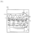
- FIG. 1 is a schematic sectional view of an image forming apparatus.
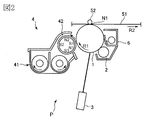
- FIG. 2 is a schematic sectional view of the image forming unit.
- FIG. 3 is a schematic sectional view of the developing device.
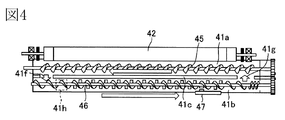
- FIG. 4 is a schematic top view of the developing device.
- FIG. 5 is a block diagram showing a control mode of the main part of the image forming apparatus.
- FIG. 6 is a schematic cross-sectional view for explaining the air flow inside the developing container.
- FIG. 7 is a schematic diagram showing the movement of the developer and the airflow around the developing sleeve.
- FIG. 8 is a graph showing the relationship between the peripheral speed of the developing sleeve and the toner scattering amount.
- FIG. 9 is a graph for explaining the stopping operation of the developing device in the first embodiment.
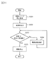
- FIG. 10 is a flowchart of the stopping operation of the developing device in the first embodiment.
- FIG. 11 is a graph showing the relationship between the toner concentration of the developer and the toner scattering amount.
- FIG. 12 is a graph showing the relationship between the peripheral speed of the developing sleeve and the toner charge amount for each toner concentration of the developer.
- FIG. 13 is a graph for explaining the stopping operation of the developing device according to the second embodiment.
- FIG. 14 is a flowchart of the stopping operation of the developing device according to the second embodiment.
- FIG. 15 is a graph showing the relationship between the peripheral speed of the developing sleeve and the toner scattering amount for each relative humidity.
- FIG. 16 is a graph for explaining the stopping operation of the developing device according to the third embodiment.
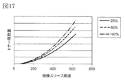
- FIG. 17 is a graph showing the relationship between the peripheral speed of the developing sleeve and the toner scattering amount for each printing rate.
- FIG. 18 is a graph for explaining the stopping operation of the developing device according to the fourth embodiment.
- 19A and 19B are graphs for explaining another example of the stopping operation of the developing device.
- FIG. 1 is a schematic cross-sectional view of an image forming apparatus 100 of the present embodiment.
- the image forming apparatus 100 according to the present exemplary embodiment is a tandem type laser beam printer that employs an intermediate transfer method that can form a full-color image using an electrophotographic method.
- the image forming apparatus 100 includes first, second, third, and fourth image forming units PY, PM, and yellow that respectively form yellow (Y), magenta (M), cyan (C), and black (K) images.
- PC, PK For the elements having the same or corresponding functions or configurations provided in each image forming unit PY, PM, PC, PK, Y, M, C, In some cases, K may be omitted for general explanation.
- FIG. 2 is a schematic cross-sectional view of the image forming unit P.
- the image forming unit P includes a photosensitive drum 1, a charging roller 2, an exposure device 3, a developing device 4, a primary transfer roller 52, and a drum cleaning device 6 which will be described later.
- a photosensitive drum 1 that is a rotatable drum-type photosensitive member (electrophotographic photosensitive member) as an image carrier that carries a toner image is driven to rotate in the direction of arrow R1 (clockwise) in the drawing.
- the surface of the rotating photosensitive drum 1 is uniformly charged to a predetermined potential having a predetermined polarity (negative polarity in this embodiment) by a charging roller 2 as a charging unit.
- a predetermined charging voltage charging bias
- the charged surface of the photosensitive drum 1 is scanned and exposed in accordance with image information by an exposure device (laser scanner) 3 as an exposure unit, and an electrostatic latent image (electrostatic image) is formed on the photosensitive drum 1.
- the exposure apparatus 3 is configured as one unit capable of exposing each photosensitive drum 1 of each image forming unit S.
- the electrostatic latent image formed on the photosensitive drum 1 is developed (visualized) by a developing device 4 as a developing unit, and a toner image is formed on the photosensitive drum 1.
- the same polarity as the charging polarity of the photosensitive drum 1 (negative polarity in this embodiment) is applied to the exposed portion on the photosensitive drum 1 where the absolute value of the potential has been lowered by being exposed after being uniformly charged. ) Is charged with charged toner (reverse development).
- the developing device 4 will be described in detail later.
- a transfer device 5 is arranged above each photosensitive drum 1 in the drawing.
- the transfer device 5 includes an intermediate transfer belt 51 configured by an endless belt as an intermediate transfer member, which is disposed so as to face each photosensitive drum 1 of each image forming unit S.
- the intermediate transfer belt 51 is stretched around a plurality of stretching rollers and stretched with a predetermined tension.
- the intermediate transfer belt 51 rotates (circulates) in the direction of the arrow R2 in the figure when a driving roller that is one of a plurality of stretching rollers is rotationally driven.
- a primary transfer roller 52 as a primary transfer unit is disposed at a position facing each photosensitive drum 1 on the inner peripheral surface side of the intermediate transfer belt 51.
- the primary transfer roller 52 is pressed toward the photosensitive drum 1 through the intermediate transfer belt 51 to form a primary transfer portion N1 where the photosensitive drum 1 and the intermediate transfer belt 51 are in contact with each other.
- a secondary transfer roller 53 as a secondary transfer unit is disposed on the outer peripheral surface side of the intermediate transfer belt 51 at a position facing a secondary transfer counter roller which is one of a plurality of stretching rollers. .
- the secondary transfer roller 53 is pressed toward the secondary transfer counter roller via the intermediate transfer belt 51 to form a secondary transfer portion N2 where the intermediate transfer belt 51 and the secondary transfer roller 53 are in contact with each other.
- the toner image formed on the photosensitive drum 1 as described above is transferred (primary transfer) onto the rotating intermediate transfer belt 51 in the primary transfer portion N1.
- the primary transfer roller 52 is supplied from a primary transfer power source (not shown) with a DC voltage having a polarity (positive in this embodiment) opposite to the toner charging polarity (normal charging polarity) at the time of development.
- a certain primary transfer voltage (primary transfer bias) is applied.
- yellow, magenta, cyan, and black toner images formed on each photosensitive drum 1 are sequentially transferred so as to be superimposed on the intermediate transfer belt 51.
- the toner image formed on the intermediate transfer belt 51 is a recording material such as paper (recording medium, transfer material, and the like) that is nipped and conveyed between the intermediate transfer belt 51 and the secondary transfer roller 53 in the secondary transfer portion N2.
- a sheet (S) is transferred (secondary transfer).
- a secondary transfer roller 53 receives a secondary transfer from a secondary transfer power source (not shown) having a DC voltage having a polarity opposite to the normal charging polarity of the toner (positive in this embodiment). A voltage is applied.
- the recording material S is accommodated in a cassette 9 as a recording material accommodation portion.
- the recording material S accommodated in the cassette 9 is conveyed to the registration roller 11 by a feeding / conveying unit 10 provided with a pickup roller, a conveyance roller, and the like. Then, the recording material S is supplied to the secondary transfer portion N2 by the registration roller 11 in timing with the toner image on the intermediate transfer belt 51.
- the recording material S to which the toner image has been transferred is conveyed to a fixing device 12 as a fixing unit, and is heated and pressed by the fixing device 12 so that the toner image is fixed (melted and fixed). It is discharged to the outside of 100 apparatus main bodies 110.
- the toner (primary transfer residual toner) remaining on the surface of the photosensitive drum 1 after the primary transfer is removed from the surface of the photosensitive drum 1 and collected by a drum cleaning device 6 as a photosensitive member cleaning means. Further, the toner (secondary transfer residual toner) remaining on the surface of the intermediate transfer belt 51 after the secondary transfer is removed from the surface of the intermediate transfer belt 51 and collected by the belt cleaning device 7 as an intermediate transfer body cleaning unit. . 2. Development device
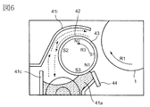
- FIG. 3 is a schematic cross-sectional view of the developing device 4 as viewed in the direction of the rotation axis of the photosensitive drum 1.
- FIG. 4 is a schematic top view of the developing device 4 in a state where an upper lid 41i described later is opened.
- the developing device 4 in this embodiment uses a two-component developer including non-magnetic toner particles (toner) and magnetic carrier particles (carrier) as a developer.
- the developing device 4 includes a developing container 41 that stores a developer.
- the developing container 41 is provided with an opening 41 d at a portion facing the photosensitive drum 1.
- a hollow cylindrical developing sleeve 42 as a developer carrying member is rotatably provided in the developing container 41 so that a part of the opening 41d is exposed to the outside.
- the developing sleeve 42 is made of a nonmagnetic material.
- the developing sleeve 42 is rotationally driven in the direction indicated by an arrow R3 (counterclockwise) in the drawing by a driving unit 120 (FIG. 5) as driving means.
- the developing sleeve 42 is rotationally driven in a direction in which the photosensitive drum 1 and the developing sleeve 42 move in the forward direction at a portion (developing region) between the photosensitive drum 1 and the developing sleeve 42.
- the drive unit 120 includes a DC motor as a drive source and a drive transmission member such as a gear.
- a magnet roll (magnet) 43 is disposed as a magnetic field generating means.
- the magnet roll 43 is fixed to the developing container 41 so as not to rotate.
- the magnet roll 43 has a plurality of magnetic poles along the circumferential direction.
- the amount (layer thickness) of the developer carried on the surface of the developing sleeve 42 is regulated at one edge of the opening 41d of the developing container 41 (the upstream edge in the rotation direction of the developing sleeve 42).
- a developing blade 44 as a regulating member is provided.
- the inside of the developing container 41 is divided into a developing chamber 41a and a stirring chamber 41b by a partition wall 41c extending in a substantially vertical direction. Delivery portions 41f and 41g that allow the developer to pass between the developing chamber 41a and the stirring chamber 41b are provided at both ends in the longitudinal direction of the partition wall 41c (left and right sides in FIG. 4).
- the developing chamber 41a, the stirring chamber 41b, and the transfer portions 41f and 41g constitute a developer transport path.
- the upper part of the container main body 41e that forms the developing chamber 41a and the stirring chamber 41b is closed by an upper lid 41i, and an opening 41d that faces the photosensitive drum 1 is formed by the container main body 41e and the upper lid 41i.
- a first screw 45 as a conveying member is disposed inside the developing chamber 41a, and a second screw 46 as a conveying member is disposed inside the stirring chamber 41b.
- the first and second screws 45 and 46 are screw members each provided with a spiral blade as a transport unit around the axis (rotation axis) of the magnetic body.
- the first and second screws 45 and 46 are driven in conjunction with the developing sleeve 42 by distributing the driving force from the driving unit 120 that drives the developing sleeve 42.
- the first screw 45 agitates and conveys the developer in the developing chamber 41a.
- the second screw 46 agitates and conveys the toner supplied into the agitating chamber 41b via the replenishing port 41h and the developer in the agitating chamber 41b, so that the toner concentration of the developer is uniform.
- the first and second screws 45 and 46 rotate around a rotation axis substantially parallel to the rotation axis direction (development width direction) of the developing sleeve 42.
- the first and second screws 45 and 46 convey the developer in opposite directions along the rotational axis direction of the developing sleeve 42. As a result, the developer is circulated through the inside of the developing container 41 via the transfer portions 41f and 41g.
- the developer in the developing chamber 41a in which the toner is consumed in the developing process and the toner concentration is lowered moves into the stirring chamber 41b through one connecting portion 41f (left side in FIG. 4).
- a toner hopper 8 (FIG. 1) as a replenishing device is connected to a replenishing port 41h provided in the vicinity of the most upstream part of the stirring chamber 41b.
- the toner discharge port (not shown) of the toner hopper 8 is provided with a replenishing screw (not shown) for transporting the toner. Then, an amount of toner commensurate with the amount consumed by the development is supplied from the toner hopper 8 to the stirring chamber 41b through the supply port 41h.
- the developer in the stirring chamber 41b that has been stirred and mixed with the replenished toner moves to the developing chamber 41a via the other connecting portion 41g (right side in FIG. 4). Then, the developer that has moved to the developing chamber 41 a is supplied to the developing sleeve 42.
- the developer container 41 has an inductance for detecting the magnetic permeability of the developer in the stirring chamber 41b as a developer concentration detecting means for detecting the toner concentration T / D of the developer (ratio of the toner weight to the developer weight).
- a sensor 47 is provided.
- the inductance sensor 47 generally detects T / D as follows. An induced current is generated in the coil in accordance with the amount of magnetic material contained in the space in the detection region. The amount of current changes depending on the ratio of the toner, the carrier, and the gap in the detection area. Then, T / D can be detected based on the potential difference between the potential due to the current and the reference voltage applied to the other coil.
- toner replenishment operation control toner replenishment control for the developing device 4 will be described in the second embodiment, which is more relevant.
- the toner supply control employed in this embodiment is the same as that described in the second embodiment.
- the developer is charged negatively and the carrier is positively charged by friction in the process of being conveyed while being stirred.
- the developer that has moved to the developing chamber 41a is in a state where the toner adheres to the surface of the carrier.
- the developer is attracted to the surface of the developing sleeve 42 by the magnetic field generated by the pumping magnetic pole S ⁇ b> 3 of the magnet roll 43 and is carried on the developing sleeve 42.
- a developer pool is formed in the vicinity of the pumping magnetic pole S3 on the developing sleeve.
- the developer on the developing sleeve 42 is conveyed by the rotation of the developing sleeve 42, and forms a magnetic spike that is raised by the magnetic field generated by the cut magnetic pole N ⁇ b> 1 of the magnet roll 43.
- the developer magnetic head is regulated by the developing blade 44 arranged to face the cut magnetic pole N1 so that the magnetic spike of the developer has a predetermined length.
- a predetermined amount of developer is conveyed to the developing area where the photosensitive drum 1 and the developing sleeve 42 face each other.
- the developer on the developing sleeve 42 forms magnetic spikes that are spiked by the magnetic field generated by the developing magnetic pole S 1 of the magnet roll 43.
- the magnetic spike on the developing sleeve 42 contacts the photosensitive drum 1 in the developing region. Then, toner is supplied to the photosensitive drum 1 from the magnetic spikes of the developer, whereby the electrostatic image on the photosensitive drum 1 is developed as a toner image. At this time, a developing voltage (developing bias) in which a DC voltage and an AC voltage are superimposed is applied to the developing sleeve 42 from a developing power source (not shown). This improves the development efficiency, that is, the rate of toner application to the electrostatic latent image.
- the developer on the developing sleeve 42 after supplying the toner to the photosensitive drum 1 is conveyed by the magnetic field generated by the conveying magnetic pole N2 of the magnet roll 43 and the rotation of the developing sleeve 42.
- the developer is peeled off from the surface of the developing sleeve 42 by the repulsive magnetic field formed by the peeling magnetic pole S2 and the pumping magnetic pole S3 of the magnet roll 43 having the same polarity, and returns to the developing chamber 41a. . 3. Control mode
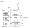
- FIG. 5 is a block diagram illustrating a control mode of a main part of the image forming apparatus 100.
- the operation of each unit of the image forming apparatus 100 is controlled by a control unit 150 provided in the apparatus main body 110.
- the control unit 150 includes a CPU as an arithmetic control unit and a ROM or RAM as a storage unit.
- the control unit 150 controls the image forming apparatus 100 using the RAM as a work area according to a program stored in the ROM.
- the apparatus main body 110 is connected to a host device such as an image reading device (reader) or a personal computer (not shown) so as to communicate with each other.
- a host device such as an image reading device (reader) or a personal computer (not shown) so as to communicate with each other.
- the control unit 150 processes image information from these devices by the image processing unit 153 to generate a drive signal for each unit, and the image forming unit 151 controls the operation of each unit. In addition, the control unit 150 performs toner replenishment control on the developing device 4 by the replenishment control unit 152.
- the optical sensor 54 and the temperature / humidity sensor 60 in FIG. 5 will be described in the second and subsequent embodiments. 4). Toner scattering
- FIG. 6 is a schematic cross-sectional view for explaining the air flow inside the developing container 41.
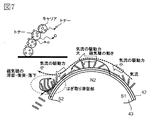
- FIG. 7 is a schematic diagram for explaining the movement of the developer and the airflow around the developing sleeve 42.
- the toner When the magnetic spike is raised by the transport magnetic pole N2, the toner may be released from the carrier by centrifugal force. Further, when the magnetic spike rising by the peeling magnetic pole S2 collides with the developer reservoir formed by the pumping magnetic pole S3 immediately before being peeled off from the developing sleeve 42, the toner is released from the carrier by the impact due to the collision. There are things to do. Further, when the developer peeled off from the developing sleeve 42 collides with the developer surface in the developing chamber 41a, the toner may be released from the carrier due to the impact caused by the collision. Further, the toner replenished to the developing container 41 may fly up into the air due to the impact of the rotation of the second screw 46 before being mixed with the developer in the developing container 41.
- the toner may scatter from the developer immediately after passing through the SB gap, which is the gap between the developing blade 44 and the developing sleeve 42.
- the SD gap which is the gap between the photosensitive drum 1 and the developing sleeve 42, when the toner is released from the carrier due to the action of the electric field, the toner that could not be recovered due to the action of the electric field may be scattered. is there.
- the amount of toner scattered through the gap between the developing sleeve 42 and the upper lid 41i tends to increase. That is, the toner scattered inside the developing container 41 is likely to be scattered on the airflow flowing from the inside of the developing container 41 to the outside along the surface of the upper cover 41 i in the gap between the developing sleeve 42 and the upper cover 41 i.
- toner scattering can be suppressed by attaching a seal member such as a urethane sheet to the developing blade 44.
- the toner scattering amount is relatively small.
- the toner scattering due to the above-described various factors, particularly the toner scattering through the gap between the developing sleeve 42 and the upper lid 41i, is a steady air flow while the developing device 4 is being driven (the developing sleeve 42 is rotating in a steady state). Occurs when the is formed.
- Such toner scattering during driving of the developing device 4 can be countered by, for example, the configurations described in Patent Documents 1 and 2 described above.
- the path of the airflow flowing from the outside to the inside of the developing container 41 in the air flow while the developing device 4 is driven becomes the path of the airflow that flows out from the inside of the developing container 41 to the outside when the developing apparatus 4 is stopped. Therefore, the air containing the toner inside the developing container 41 flows out to the outside of the developing container 41 at a stretch. As a result, irregular toner scattering from the developing device 4 occurs when the developing device 4 is stopped. 5). Toner scattering control
- the amount of toner released from the carrier in a steady state while the developing device 4 is driven is greatly influenced by the centrifugal force according to the rotation speed of the developing sleeve 42, except for fluctuation factors due to physical properties such as the toner charge amount. For this reason, the liberation amount varies greatly depending on the square of the angular velocity of the developing sleeve 42, that is, the rotational speed of the developing sleeve 42. Also, some of the kinetic energy lost due to the collision between the developers by the stripping magnetic pole S2 and part of the kinetic energy lost when the developer peeled off from the developing sleeve 42 collides with the developer surface in the developing chamber 41a. , Acting as a force to release the toner from the carrier.
- the air flow generated by the rotation of the developing sleeve 42 also increases in proportion to the rotation speed of the developing sleeve 42. Therefore, the faster the developing sleeve 42 rotates, the easier the toner released from the carrier rides on the airflow and flows out of the developing container 41.
- the rotation speed of the developing sleeve 42 is represented by “peripheral speed”.
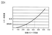
- FIG. 8 shows the relationship between the peripheral speed of the developing sleeve 42 and the toner scattering amount.
- the paper is placed in the vicinity of the gap between the developing sleeve 42 and the upper lid 41i, the developing device 4 is idled for a predetermined time, and the amount of toner adhering to the paper is measured as an integral value of the adhering area and density to determine the toner. The amount of scattering was used.
- FIG. 9 shows the relationship between the time from when the developing sleeve 42 rotates in a steady state until it stops (herein also referred to as “driving stop time”) and the peripheral speed of the developing sleeve 42.
- the peripheral speed of the developing sleeve 42 is 420 [mm / sec] in a steady state during driving of the developing device 4 (FIG. 8). Then, when the drive by the drive unit 120 is simply stopped (the DC motor is turned off) from the state in which the development sleeve 42 is rotationally driven by the drive unit 120 at the steady peripheral speed, the development sleeve is taken in about 200 msec. The rotation of 42 stops (broken line in FIG. 9). If the rotation of the developing sleeve 42 is suddenly stopped in this way, toner scattering occurs at a level that causes a problem for the reasons described above.
- the control unit 150 changes the developing sleeve 42 from being driven and rotated by the driving unit 120 to being stopped without being driven by the driving unit 120 (during the stop operation). ), The following control is performed. That is, the control unit 150 stops the driving of the developing sleeve 42 by the driving unit 120 after reducing the driving speed of the developing sleeve 42 by the driving unit 120.
- the driving speed of the developing sleeve 42 by the driving unit 120 is set so that the peripheral speed of the developing sleeve 42 is a peripheral speed that can sufficiently suppress the blowing of air containing toner from the developing container 4. Until it slows down at a low deceleration rate. Then, after the peripheral speed of the developing sleeve 42 reaches a peripheral speed at which toner scattering can be suppressed, the driving of the developing sleeve 42 by the driving unit 120 is stopped (the DC motor is turned off).
- the peripheral speed of the developing sleeve 42 is decelerated at a deceleration rate higher than the deceleration rate until then, but since the toner has been decelerated so far, toner scattering can be sufficiently suppressed. .
- irregular toner scattering during the stop operation of the developing device 4 depends on the peripheral speed of the developing sleeve 42. Therefore, when the developing device 4 is stopped, it is desired to slowly stop the rotation of the developing sleeve 42 in a state where the airflow is stabilized. However, it is not preferable to extend the drive stop time more than necessary in consideration of stress on the developing sleeve 42 and the developer.
- the peripheral speed of the developing sleeve 42 is once decelerated at a low deceleration rate to a predetermined peripheral speed that can suppress irregular toner scattering. Then, after the airflow is stabilized by decelerating to a predetermined peripheral speed, the driving of the developing sleeve 42 is stopped. Thereby, irregular toner scattering during the stop operation of the developing device 4 can be suppressed. This will be described in more detail below.
- the developing sleeve 42 is slowly decelerated from a state where the developing sleeve 42 is rotating at a high speed to a predetermined peripheral speed at which the toner scattering amount is sufficiently reduced. It is desirable to stop completely.
- the amount of toner scattering changes with the power of the peripheral speed of the developing sleeve 42 (about the square in the configuration of this embodiment). Therefore, in order to reduce the toner scattering amount, it is desired to suppress a rapid speed change on the high speed side of the developing sleeve 42. For this reason, in this embodiment, when the developing device 4 is stopped, the fluctuation in the peripheral speed of the developing sleeve 42 immediately after the stop request is reduced.
- the peripheral speed of the developing sleeve 42 having a diameter of 20 [mm] is the first rotational speed. 420 [mm / sec].
- the peripheral speed of the photosensitive drum 1 having a diameter of 30 [mm] is 240 [mm / sec].
- the developer has a toner concentration T / D of 12%.
- the threshold of the peripheral speed of the developing sleeve 42 (also referred to as “stop upper limit speed” here) that can sufficiently suppress the toner scattering is the second rotation.
- the speed is 280 [mm / sec].
- the circumferential speed of the photosensitive drum is 160 [mm / sec]. That is, the amount of scattered toner can be sufficiently reduced by stopping the driving of the developing sleeve 42 by the driving unit 120 from the state where the peripheral speed of the developing sleeve 42 is equal to or lower than the upper limit stop speed as a predetermined peripheral speed.
- the stop upper limit speed is not limited to the value in this embodiment, and can be set as appropriate so that toner scattering can be sufficiently suppressed.
- the deceleration rate of the peripheral speed of the developing sleeve 42 means a decrease amount of the peripheral speed of the developing sleeve 42 with respect to time (negative acceleration). Since the deceleration rate is acceleration, it is represented by a coefficient that is multiplied by the square value of time. That is, the speed difference is divided by the time. However, the present invention is not limited to this, and an exponential coefficient, a logarithmic coefficient, or the like may be used.
- the driving speed of the developing sleeve 42 by the driving unit 120 is the developing sleeve in a state where the driving unit 120 transmits driving force to the developing sleeve 42 (a state in which the developing sleeve 42 is rotated at a certain rotational speed). Means a rotational speed of 42. This drive speed typically corresponds to the rotational speed of the drive shaft of the drive source in the state where the drive force is transmitted.
- FIG. 10 is a flowchart showing the flow of the stopping operation of the developing device 4.
- the control unit 150 determines whether the peripheral speed of the developing sleeve 42 is larger than the upper limit stop speed (S102).
- a job is a series of operations for forming and outputting an image on one or a plurality of recording materials S according to one start instruction.
- the control unit 150 is configured so that the developing sleeve 42 is driven by the driving unit 120 at the first deceleration rate set in advance as described above (the deceleration rate is increased as the speed is lower) until the peripheral speed of the developing sleeve 42 reaches the upper limit speed.
- the peripheral speed of the developing sleeve 42 can be obtained from a detection result by a rotation speed detection unit that detects the rotation speed of the DC motor of the drive unit 120, for example.
- a rotation speed detection unit that detects the rotation speed of the DC motor of the drive unit 120
- any available mechanism a mechanism for detecting the rotational speed of the drive shaft with an encoder, a mechanism for electrically detecting the rotational speed, etc.
- the peripheral speed of the developing sleeve 42 at each timing in the operation sequence of the image forming apparatus 100 can be obtained in advance. Therefore, the stop operation according to the present embodiment can be performed by performing the stop operation of the developing device 4 according to a preset stop pattern.
- the control unit 150 reduces the driving speed of the developing sleeve 42 by the driving unit 120 until the peripheral speed of the developing sleeve 42 reaches a predetermined peripheral speed during the stop operation. Is decelerated at the first deceleration rate. Then, the control unit 150 stops the driving of the developing sleeve 42 by the driving unit 120 after the peripheral speed of the developing sleeve 42 reaches a predetermined peripheral speed, so that the peripheral speed of the developing sleeve 42 is made higher than the first reduction rate. Decelerate and stop at a high second deceleration rate.
- the first deceleration rate is set such that the deceleration rate increases as the peripheral speed of the developing sleeve 42 decreases.
- first deceleration rate (first rotation speed ⁇ second rotation speed) / time required for deceleration
- second deceleration rate second rotation speed / second rotation speed to stop. It is calculated in the time required.
- the motor is turned off after reaching the stop upper limit speed.
- a target may be set to a new rotation speed smaller than the stop upper limit speed, and the motor may be turned off after reaching the new rotation speed.
- a configuration in which the image forming apparatus has a plurality of image forming speeds and a plurality of rotation speeds of the developing sleeves 42 in association therewith will be described.
- the above stop control is executed.
- the control unit 150 does not perform the above control and turns off the rotation of the developing sleeve 42 after the end of the developing process. Control.
- the stop upper limit speed may be selected and set from the rotation speeds of the plurality of developing sleeves 42. 6).
- the toner scattering amount from the developing device 4 during the stop operation of the developing device 4 was compared between the configuration of this example and the conventional configuration.
- the conventional configuration is substantially the same as the configuration of the present embodiment except that the operation of reducing the drive speed of the developing sleeve 42 by the drive unit 120 is not performed when the developing device 4 is stopped.
- the toner adheres to the upper lid 41i of the developing device 4 and the flange of the developing sleeve 42 at a level where there is a concern that the toner adheres to the charging device 2 and the exposure device 3 when an image is formed over a long period of time.
- toner adhesion at a problematic level was not observed.
- the toner density T / D of the developer in the developing device 4 is detected, and the stop pattern of the developing sleeve 42 during the stop operation of the developing device 4 is optimized according to the detected T / D.
- the stop pattern of the developing sleeve 42 at least one of the stop upper limit speed or the deceleration rate up to the stop upper limit speed can be optimized. In this embodiment, the deceleration rate up to the stop upper limit speed is optimized.
- the release of toner from the carrier is caused by factors such as impact and centrifugal force.
- This adhesion force includes electrostatic adhesion force such as Coulomb force and non-electrostatic adhesion force such as liquid cross-linking force, but electrostatic adhesion force is dominant.
- the charge amounts of the toner and the carrier are determined by the probability of contact of the toner with the carrier, and the charge amount increases as T / D decreases.
- FIG. 11 shows the relationship between T / D and the charge amount of toner. As shown in the figure, the charge amount of the toner is almost inversely proportional to T / D.
- FIG. 12 shows the relationship between the peripheral speed of the developing sleeve 42 and the toner scattering amount when T / D is 8%, 10%, and 12%, respectively. From the figure, it can be seen that the higher the T / D, the easier the toner scattering occurs. Therefore, it is desirable to decrease the deceleration rate up to the stop upper limit speed as T / D increases.
- the toner replenishment control for the developing device 4 will be described.
- the image forming apparatus 100 performs automatic toner replenishment (ATR) that replenishes the developing device 4 with an amount of toner corresponding to the amount consumed by development.
- ATR automatic toner replenishment
- the control unit 150 controls the number of rotations of the replenishing screw of the toner hopper 8 according to the printing rate (image area ratio) at the time of image formation, the detection result of the inductance sensor 47, and the detection result of the image density of the patch image. 41 is replenished with toner. That is, the toner replenishment amount corresponding to the toner consumption amount predicted from the printing rate at the time of image formation is obtained.
- the toner supply amount based on the printing rate is corrected. Further, the target value of the detection result of the inductance sensor 47 is corrected using the density detection result of the patch image formed at a predetermined frequency.
- an arbitrary replenishment amount is not replenished at any time, but the replenishment amount is reduced to a preset replenishment amount (one rotation of the replenishment screw of the toner hopper 8 in this embodiment). The supply screw is rotated once for each supply amount. Thereby, a stable replenishment amount can be obtained.
- the image processing unit 153 of the control unit 150 calculates a toner consumption amount due to image formation based on image information received from an image reading device or a personal computer connected via a network or the like.
- the toner consumption is obtained from the printing rate based on the video count value (image signal value) integrated based on the image information, and integrated for each image output.
- the replenishment control unit 152 of the control unit 150 obtains the toner amount corresponding to the toner consumption amount as the toner replenishment amount, but the T / D detected by the inductance sensor 47 is deviated from the T / D target value.
- the toner replenishment amount is corrected so as to reduce the deviation.
- the replenishment control unit 152 rotates the replenishment screw by the necessary number of rotations to replenish toner to the developing device 4. To do.
- the replenishment control unit 152 forms a patch image of a predetermined size (for example, 15 mm square) with a predetermined latent image contrast on the photosensitive drum 1 at a predetermined frequency (for example, for each predetermined number of image outputs), and this is transferred to the intermediate transfer. Transfer to the belt 51. Then, the image density (reflection density) of the patch image is measured on the intermediate transfer belt 51 by an optical sensor 54 (FIGS. 1 and 5) as image density detection means. Then, the measured image density is compared with the reference image density, and the target value of T / D is changed so as to reduce the deviation of the image density (patch detection control).
- the toner charge amount can be predicted from the toner amount used for forming the patch image, and the variation in the image density caused by the change in the toner charge amount due to the deterioration of the carrier can be dealt with.
- the control unit 150 changes the deceleration rate up to the stop upper limit speed according to the T / D detection result by the inductance sensor 47.
- the control unit 150 performs control so that the deceleration rate up to the stop upper limit speed is decreased stepwise as T / D increases.
- the control unit 150 performs the process up to the stop upper limit speed according to the average value of the T / D detection results by the inductance sensor 47 from the patch detection control immediately before the job ends to immediately before the job. Change the deceleration rate. That is, in this embodiment, the average value of the detection results of T / D when the driving of the developing device 4 is stopped in a state where the target value of T / D is set to the latest.
- T / D detection result after the patch detection control is ignored. Note that the detection result of T / D at an arbitrary timing can be used as long as it can be used as an index of the ease of toner scattering during the stop operation of the developing device 4.
- FIG. 13 shows the relationship between the driving stop time and the peripheral speed of the developing sleeve 42 from the state in which the developing sleeve 42 rotates in a steady state to the stop in the present embodiment.
- T / D is 8% or more and less than 10% (solid line in FIG. 13), 10% or more and less than 12% (broken line in FIG. 13), 12% or more (dashed line in FIG. 13).
- the deceleration rate to the stop upper limit speed is lowered stepwise.
- the attenuation rate up to the stop upper limit speed in each case is set such that the deceleration rate increases as the peripheral speed decreases until the stop upper limit speed is reached.
- FIG. 14 is a flowchart showing the flow of the stopping operation of the developing device 4 in this embodiment.
- the control unit 150 determines a deceleration rate up to the stop upper limit speed based on the detection result of T / D (S202). Thereafter, the control unit 150 determines whether or not the peripheral speed of the developing sleeve 42 is greater than the stop upper limit speed (S203).
- the control unit 150 sets the driving speed of the developing sleeve 42 by the driving unit 120 at the deceleration rate determined as described above (the deceleration rate is increased as the speed decreases) until the peripheral speed of the developing sleeve 42 reaches the stop upper limit speed.
- the image forming apparatus 100 includes the inductance sensor 47 that detects the toner concentration as a concentration detection unit that detects the concentration of the developer contained in the developing container 41.
- the control unit 150 changes the deceleration rate (first deceleration rate) up to the stop upper limit speed according to the detection result of the inductance sensor 47.
- the control unit 150 uses the first deceleration rate when the toner density is a second density higher than the first density than when the toner density is the first density. Lower the direction.
- T / D was varied as 8%, 10%, and 12%, and the same test for checking the level of toner scattering as in Example 1 was performed.
- T / D is 8% which is relatively low, even if the deceleration rate to the stop upper limit speed is relatively high, adhesion of toner to the periphery of the developing device 4 at the level at which the problem occurs is observed. I could't.
- T / D is relatively high of 12%, adhesion of toner to the periphery of the developing device 4 at a problematic level can be seen by making the deceleration rate to the stop upper limit speed relatively low. There wasn't.
- the amount of toner adhering to the periphery of the developing device 4 was substantially the same.
- the toner scattering can be sufficiently suppressed even in a situation where the toner scattering from the developing device 4 is likely to occur during the stop operation of the developing device 4. Further, according to the present embodiment, in a situation where the toner scattering from the developing device 4 is difficult to occur during the stopping operation of the developing device 4, the toner is suppressed while suppressing an increase in the driving stop time of the developing sleeve 42 more than necessary. Scattering can be suppressed.
- the driving speed of the developing sleeve 42 by the driving unit 120 is reduced when T / D is less than a predetermined value (for example, 8%). The operation may not be performed.
- the T / D range (step size) for changing the deceleration rate is not limited to the range of the present embodiment, and can be set as appropriate so that toner scattering can be sufficiently suppressed.
- the concentration detection means for detecting the concentration of the developer stored in the developing container 41 is not limited to the inductance sensor, and any appropriate means can be used.
- the developer concentration indirectly obtained from information such as toner consumption amount and toner supply amount based on image information may be used.
- the environment of the developer atmosphere is detected (measured or predicted), and the stop pattern of the developing sleeve 42 during the stop operation of the developing device 4 is optimized according to the detected environment.
- the environment is typically at least one of temperature and relative humidity in at least one of the inside and the outside of the developing device 4.
- the relative humidity is obtained by detecting the temperature and humidity inside the developing device 4, and the stop pattern of the developing sleeve 42 is optimized according to the relative humidity.
- the stop pattern of the developing sleeve 42 the deceleration rate up to the stop upper limit speed is optimized as in the second embodiment.
- FIG. 15 shows the relationship between the peripheral speed of the developing sleeve 42 and the toner scattering amount when the relative humidity inside the developing device 4 is 5%, 50%, and 80%, respectively. From the figure, it can be seen that toner scattering is more likely to occur as the relative humidity inside the developing device 4 increases. Therefore, it is desirable to decrease the deceleration rate up to the stop upper limit speed as the relative humidity inside the developing device 4 is higher.
- the developing device 4 is provided with a temperature / humidity sensor 60 (FIG. 5) for detecting the temperature and humidity inside the developing device 4 as environment detecting means.
- the control unit 150 obtains the relative humidity of the developer atmosphere in the developing device 4 based on the temperature and humidity detection results input from the temperature and humidity sensor 60.
- the control unit 150 when the obtained relative humidity is 45% or more, changes the deceleration rate up to the stop upper limit speed according to the value of the relative humidity. In the present embodiment, the control unit 150 performs control so that the deceleration rate up to the stop upper limit speed is decreased stepwise as the relative humidity increases. On the other hand, in this embodiment, when the obtained relative humidity is less than 45%, the control unit 150 does not perform an operation of reducing the driving speed of the developing sleeve 42 by the driving unit 120 when the developing device 4 is stopped.
- FIG. 16 shows the relationship between the drive stop time and the peripheral speed of the developing sleeve 42 from the state in which the developing sleeve 42 rotates in a steady state to the stop in the present embodiment.
- the relative humidity inside the image forming apparatus 100 is controlled to be between 5% and 80%.
- the relative humidity is less than 45% (solid line in FIG. 16)
- the driving of the developing sleeve 42 is simply stopped (the DC motor is turned off) when the developing device 4 is stopped.
- the relative humidity is 45% or more and 80% or less
- the deceleration rate up to the stop upper limit speed is decreased stepwise as the relative humidity increases for each predetermined increment (see FIG. 16).
- the attenuation rate up to the stop upper limit speed is set such that the deceleration rate increases as the peripheral speed decreases until the stop upper limit speed is reached.
- control unit 150 decelerates the deceleration rate up to the stop upper limit speed (or the driving speed of the developing sleeve 42 by the driving unit 120) based on the detection result of the relative humidity of the developer atmosphere. Decide not to take action).
- the image forming apparatus 100 is a temperature / humidity sensor 60 that detects the relative humidity in the developing container 41 as an environment detecting unit that detects the environment of the developer contained in the developing container 41.
- the control unit 150 changes the deceleration rate (first deceleration rate) up to the stop upper limit speed according to the detection result of the temperature / humidity sensor 60.
- the control unit 150 performs the first operation when the environmental humidity is a second humidity higher than the first humidity than the first deceleration rate when the environmental humidity is the first humidity. Decrease the deceleration rate.
- Example 2 the same humidity test as in Example 1 was performed to examine the level of toner scattering while shaking the relative humidity between 5% and 80%.
- the relative humidity is less than 45%, no toner adheres to the periphery of the developing device 4 at a problematic level without performing an operation of reducing the driving speed of the developing sleeve 42. It was.
- the relative humidity is 45% to 80%, the reduction rate up to the stop upper limit speed is increased as the relative humidity increases, so that the toner adheres to the periphery of the developing device 4 at a problematic level. was not seen.
- the amount of toner adhered to the periphery of the developing device 4 was substantially the same.
- the configuration for detecting relative humidity which is the configuration for detecting relative humidity
- the configuration for detecting relative humidity may be used.
- the relative humidity inside the developing device 4 is directly detected
- the temperature and humidity outside the apparatus main body 110 and the temperature of the developing device 4 are detected to detect the relative humidity inside the developing device 4.
- a configuration for calculating (predicting) humidity may be employed.
- the control unit 150 sets the deceleration rate (the first speed to the stop upper limit speed). (Deceleration rate) may be changed as follows. That is, the first deceleration rate when the environmental temperature is the second temperature higher than the first temperature is made lower than the first deceleration rate when the environmental temperature is the first temperature. You can do it.
- the control according to T / D described in the second embodiment and the control according to relative humidity described in the present embodiment may be combined.
- the deceleration rate up to the stop upper limit speed for each T / D within a predetermined range may be set for each of the relative humidity with a predetermined step size.
- the relative humidity is less than a predetermined value (for example, 45%) and T / D is less than the predetermined value (for example, 8%)
- the operation of reducing the driving speed of the developing sleeve 42 by the driving unit 120 is not performed. It can be.
- the relative humidity is equal to or higher than the predetermined value and T / D is equal to or higher than the predetermined value
- an operation of reducing the driving speed of the developing sleeve 42 by the driving unit 120 can be performed.
- the stop pattern of the developing sleeve 42 during the stop operation of the developing device 4 is optimized according to the image information. More specifically, in this embodiment, the index is obtained from the video count value (image signal value) integrated based on the image information as an index of the ease of occurrence of toner scattering inside the developing container 41 due to toner replenishment. Use the print rate.
- the deceleration rate up to the stop upper limit speed is optimized as in the second and third embodiments.
- the toner supplied to the developing container 41 is stirred by the second screw 46 before coming into contact with the carrier.
- the printing rate (image duty) 100%
- the largest amount of toner is supplied to the developing container 41.
- about 0.35 [g] is supplied per image output.
- the replenishment amount may further increase, and a maximum of about 0.50 [g] may be replenished by one replenishment. is there.
- a large amount of toner may be scattered inside the developing container 41.
- FIG. 17 shows the relationship between the peripheral speed of the developing sleeve 42 and the toner scattering amount when the average printing rate in the job immediately before the stopping operation of the developing device 4 is 25%, 80%, and 100%. From the figure, it can be seen that the higher the printing rate, the more likely toner scattering occurs. Therefore, the higher the printing rate, the lower the deceleration rate up to the stop upper limit speed.
- the drive stop time (idling time) of the developing sleeve 42 can be shortened by increasing the deceleration rate up to the stop upper limit speed. desirable.
- the control unit 150 changes the deceleration rate up to the stop upper limit speed according to the printing rate.
- the control unit 150 performs control so that the deceleration rate up to the stop upper limit speed is gradually reduced as the printing rate increases.
- the control unit 150 calculates an average printing rate in the job from the start of driving of the developing device 4 to the start of the driving stop operation, and reaches the stop upper limit speed according to the average printing rate. Change the deceleration rate.
- the average printing rate can be obtained by dividing the integrated value of the printing rate for each image output in the job by the number of image outputs in the job.
- the replenishment amount for one rotation of the replenishment screw of the toner hopper 8 is 0.175 [g]
- the replenishment amount for two rotations of the replenishment screw is one image output with a printing rate of 100%. Necessary. In other words, as a guideline, if the average printing rate is less than 50%, it is 0 to 1 rotation per image output, and if the average printing rate is 50% to 99%, it is 1 image output. When the average printing rate is 100% for 1 to 3 rotations, the replenishment amount is 2 to 3 rotations per image output.
- FIG. 18 shows the relationship between the drive stop time and the peripheral speed of the developing sleeve 42 from the state in which the developing sleeve 42 rotates in a steady state to the stop in the present embodiment.
- the upper limit of stoppage in each case where the printing rate is less than 50% (solid line in FIG. 18), 50% or more and less than 100% (broken line in FIG. 18), and 100% (dashed line in FIG. 18). Decrease the deceleration rate to the speed step by step.
- the deceleration rate up to the stop upper limit speed in each case is set such that the deceleration rate increases as the peripheral speed decreases until the stop upper limit speed is reached.
- control unit 150 determines the deceleration rate up to the stop upper limit speed based on the calculation result of the average printing rate.
- the image forming apparatus 100 includes the image processing unit 153 as a processing unit for obtaining the print rate of the output image.
- the control unit 150 changes the deceleration rate (first deceleration rate) up to the stop upper limit speed according to the printing rate obtained by the image processing unit 153.
- the control unit 150 uses the first printing rate when the printing rate is higher than the first printing rate than the first deceleration rate when the printing rate is the first printing rate. Decrease the deceleration rate.
- Example 2 the same test as in Example 1 was conducted to check the level of toner scattering, with the printing rate being changed to 25%, 80%, and 100%.
- the printing rate is relatively low of 25%, even if the deceleration rate up to the stop upper limit speed is relatively high, toner adheres to the periphery of the developing device 4 at a problematic level. There wasn't.
- the printing rate was 100%, the toner was not attached to the periphery of the developing device 4 at a problem level by making the deceleration rate up to the stop upper limit speed relatively low. Further, the amount of toner adhering to the periphery of the developing device 4 was substantially the same for any printing rate.
- the toner replenishment amount based on the printing rate may increase or decrease depending on the detection result of the inductance sensor 47. Therefore, the deceleration rate up to the stop upper limit speed determined according to the printing rate as described above can be corrected according to the detection result of the inductance sensor 47. For example, when the replenishment amount is increased according to the detection result of the inductance sensor 47, the deceleration rate up to the stop upper limit speed can be lowered according to the increase amount. Conversely, when the replenishment amount is decreased according to the detection result of the inductance sensor 47, the deceleration rate up to the stop upper limit speed can be increased according to the decrease amount. As a result, it is possible to perform control in accordance with the state of toner scattering in the developing container 41.
- the average printing rate of the first half of the job is relatively influenced by the scattering of toner in the developing container 41 during the stop operation of the developing device 4. Very few. Therefore, at the end of the job when a job of a certain length or longer (continuous image formation) is executed, the average print rate for a predetermined period immediately before the end of the job is calculated and stopped based on the average print rate The deceleration rate up to the upper limit speed can be determined. As a result, it is possible to perform control according to the average printing rate in a predetermined period in the second half of the job, which has a relatively large influence on the toner scattering in the developing container 41 during the stop operation of the developing device 4.
- the deceleration rate up to the stop upper limit speed during the stop operation of the developing device is set so that the deceleration rate increases as the peripheral speed of the developing sleeve decreases.
- the drive stop time of the developing sleeve can be shortened as much as possible while effectively suppressing a rapid change in the peripheral speed when the peripheral speed of the developing sleeve where toner scattering is likely to occur is large.
- the present invention is not limited to such an embodiment.
- the deceleration rate up to the stop upper limit speed may be substantially constant.
- the stop upper limit speed may be changed as the developing sleeve stop pattern, for example, as shown by the broken line in FIG. Further, for example, as indicated by a one-dot chain line in FIG. 19B, both the deceleration rate up to the stop upper limit speed and the stop upper limit speed may be changed.
- the relatively unlikely situation is a situation where the developer concentration is relatively low, a temperature or humidity is relatively low, or a printing rate is relatively low. Is the situation.
- the relatively likely situation is a situation where the developer concentration is relatively high, a temperature or humidity is relatively high, or a printing rate is relatively high.
- a developing device capable of suppressing toner scattering from the developing device when the driving of the developing device is stopped even when the developer carrying member rotates at a high speed during image formation. Provided.
Landscapes
- Physics & Mathematics (AREA)
- General Physics & Mathematics (AREA)
- Engineering & Computer Science (AREA)
- Life Sciences & Earth Sciences (AREA)
- Atmospheric Sciences (AREA)
- Biodiversity & Conservation Biology (AREA)
- Ecology (AREA)
- Environmental & Geological Engineering (AREA)
- Environmental Sciences (AREA)
- Microelectronics & Electronic Packaging (AREA)
- Dry Development In Electrophotography (AREA)
- Control Or Security For Electrophotography (AREA)
Applications Claiming Priority (2)
| Application Number | Priority Date | Filing Date | Title |
|---|---|---|---|
| JP2016-205363 | 2016-10-19 | ||
| JP2016205363A JP2018066860A (ja) | 2016-10-19 | 2016-10-19 | 画像形成装置 |
Publications (1)
| Publication Number | Publication Date |
|---|---|
| WO2018074613A1 true WO2018074613A1 (ja) | 2018-04-26 |
Family
ID=61903811
Family Applications (1)
| Application Number | Title | Priority Date | Filing Date |
|---|---|---|---|
| PCT/JP2017/038596 Ceased WO2018074613A1 (ja) | 2016-10-19 | 2017-10-19 | 画像形成装置 |
Country Status (3)
| Country | Link |
|---|---|
| US (1) | US10274880B2 (enExample) |
| JP (1) | JP2018066860A (enExample) |
| WO (1) | WO2018074613A1 (enExample) |
Families Citing this family (5)
| Publication number | Priority date | Publication date | Assignee | Title |
|---|---|---|---|---|
| JP6797532B2 (ja) * | 2016-02-19 | 2020-12-09 | キヤノン株式会社 | 画像形成装置 |
| JP2018072565A (ja) | 2016-10-28 | 2018-05-10 | キヤノン株式会社 | 現像装置 |
| JP6971827B2 (ja) | 2017-12-18 | 2021-11-24 | キヤノン株式会社 | 現像装置 |
| JP2021018264A (ja) * | 2019-07-17 | 2021-02-15 | 京セラドキュメントソリューションズ株式会社 | 画像形成装置 |
| JP2021033239A (ja) * | 2019-08-29 | 2021-03-01 | キヤノン株式会社 | 画像形成装置 |
Citations (3)
| Publication number | Priority date | Publication date | Assignee | Title |
|---|---|---|---|---|
| JPH0675466A (ja) * | 1992-08-27 | 1994-03-18 | Sharp Corp | 複写機の現像装置 |
| JP2009116249A (ja) * | 2007-11-09 | 2009-05-28 | Canon Inc | 画像形成装置 |
| US20110311263A1 (en) * | 2010-06-17 | 2011-12-22 | Toshiba Tec Kabushiki Kaisha | Developing device to prevent scattering of toner |
Family Cites Families (6)
| Publication number | Priority date | Publication date | Assignee | Title |
|---|---|---|---|---|
| JPH0635312A (ja) * | 1992-07-15 | 1994-02-10 | Ricoh Co Ltd | 画像形成装置 |
| JP3071672B2 (ja) | 1995-07-18 | 2000-07-31 | キヤノン株式会社 | 現像装置及び画像形成装置 |
| JP2005070583A (ja) | 2003-08-27 | 2005-03-17 | Seiko Epson Corp | 画像形成装置 |
| JP4280909B2 (ja) | 2003-08-19 | 2009-06-17 | セイコーエプソン株式会社 | 画像形成装置 |
| JP6119323B2 (ja) | 2013-03-13 | 2017-04-26 | 株式会社リコー | 現像装置、プロセスカートリッジ及び画像形成装置 |
| JP6127884B2 (ja) | 2013-10-02 | 2017-05-17 | 富士ゼロックス株式会社 | 画像形成装置及び現像装置 |
-
2016
- 2016-10-19 JP JP2016205363A patent/JP2018066860A/ja active Pending
-
2017
- 2017-10-11 US US15/729,950 patent/US10274880B2/en active Active
- 2017-10-19 WO PCT/JP2017/038596 patent/WO2018074613A1/ja not_active Ceased
Patent Citations (3)
| Publication number | Priority date | Publication date | Assignee | Title |
|---|---|---|---|---|
| JPH0675466A (ja) * | 1992-08-27 | 1994-03-18 | Sharp Corp | 複写機の現像装置 |
| JP2009116249A (ja) * | 2007-11-09 | 2009-05-28 | Canon Inc | 画像形成装置 |
| US20110311263A1 (en) * | 2010-06-17 | 2011-12-22 | Toshiba Tec Kabushiki Kaisha | Developing device to prevent scattering of toner |
Also Published As
| Publication number | Publication date |
|---|---|
| JP2018066860A (ja) | 2018-04-26 |
| US10274880B2 (en) | 2019-04-30 |
| US20180107143A1 (en) | 2018-04-19 |
Similar Documents
| Publication | Publication Date | Title |
|---|---|---|
| WO2018074613A1 (ja) | 画像形成装置 | |
| JP5173598B2 (ja) | 画像形成装置 | |
| JP2002072586A (ja) | 画像形成装置 | |
| US9158229B2 (en) | Development device and image forming apparatus including the same | |
| US9046815B2 (en) | Developing device and image forming apparatus provided therewith | |
| US20180284643A1 (en) | Developing device | |
| US10216123B2 (en) | Developing device | |
| US10261442B2 (en) | Developing apparatus and image forming apparatus | |
| JP5196942B2 (ja) | 画像形成装置 | |
| JP7412958B2 (ja) | 画像形成装置 | |
| US10054872B2 (en) | Image forming apparatus having removable developing units | |
| US10795302B2 (en) | Image forming apparatus | |
| US10901358B2 (en) | Image forming apparatus capable of executing a running-in operation for a developing section | |
| US11003110B2 (en) | Developing device | |
| JP2013174781A (ja) | 画像形成装置 | |
| JP6932548B2 (ja) | 搬送スクリュー及び現像装置 | |
| US20250208538A1 (en) | Image forming apparatus | |
| JP7412959B2 (ja) | 画像形成装置 | |
| US11307513B2 (en) | Image forming apparatus | |
| JP7330858B2 (ja) | 画像形成装置 | |
| JP2012003047A (ja) | 画像形成装置 | |
| JP2009008979A (ja) | 画像形成装置の現像制御装置 | |
| JP2022126204A (ja) | 画像形成装置 | |
| JP6314852B2 (ja) | 現像装置、およびこれを備えた画像形成装置 | |
| JP2023109708A (ja) | 現像装置 |
Legal Events
| Date | Code | Title | Description |
|---|---|---|---|
| 121 | Ep: the epo has been informed by wipo that ep was designated in this application |
Ref document number: 17862252 Country of ref document: EP Kind code of ref document: A1 |
|
| NENP | Non-entry into the national phase |
Ref country code: DE |
|
| 122 | Ep: pct application non-entry in european phase |
Ref document number: 17862252 Country of ref document: EP Kind code of ref document: A1 |