WO2018074130A1 - 天井搬送車及び搬送システム - Google Patents
天井搬送車及び搬送システム Download PDFInfo
- Publication number
- WO2018074130A1 WO2018074130A1 PCT/JP2017/033697 JP2017033697W WO2018074130A1 WO 2018074130 A1 WO2018074130 A1 WO 2018074130A1 JP 2017033697 W JP2017033697 W JP 2017033697W WO 2018074130 A1 WO2018074130 A1 WO 2018074130A1
- Authority
- WO
- WIPO (PCT)
- Prior art keywords
- mast
- lifting platform
- traveling body
- track
- traveling
- Prior art date
- Legal status (The legal status is an assumption and is not a legal conclusion. Google has not performed a legal analysis and makes no representation as to the accuracy of the status listed.)
- Ceased
Links
Images




Classifications
-
- B—PERFORMING OPERATIONS; TRANSPORTING
- B66—HOISTING; LIFTING; HAULING
- B66F—HOISTING, LIFTING, HAULING OR PUSHING, NOT OTHERWISE PROVIDED FOR, e.g. DEVICES WHICH APPLY A LIFTING OR PUSHING FORCE DIRECTLY TO THE SURFACE OF A LOAD
- B66F9/00—Devices for lifting or lowering bulky or heavy goods for loading or unloading purposes
- B66F9/06—Devices for lifting or lowering bulky or heavy goods for loading or unloading purposes movable, with their loads, on wheels or the like, e.g. fork-lift trucks
- B66F9/075—Constructional features or details
- B66F9/08—Masts; Guides; Chains
-
- B—PERFORMING OPERATIONS; TRANSPORTING
- B65—CONVEYING; PACKING; STORING; HANDLING THIN OR FILAMENTARY MATERIAL
- B65G—TRANSPORT OR STORAGE DEVICES, e.g. CONVEYORS FOR LOADING OR TIPPING, SHOP CONVEYOR SYSTEMS OR PNEUMATIC TUBE CONVEYORS
- B65G1/00—Storing articles, individually or in orderly arrangement, in warehouses or magazines
- B65G1/02—Storage devices
- B65G1/04—Storage devices mechanical
- B65G1/0407—Storage devices mechanical using stacker cranes
-
- B—PERFORMING OPERATIONS; TRANSPORTING
- B66—HOISTING; LIFTING; HAULING
- B66F—HOISTING, LIFTING, HAULING OR PUSHING, NOT OTHERWISE PROVIDED FOR, e.g. DEVICES WHICH APPLY A LIFTING OR PUSHING FORCE DIRECTLY TO THE SURFACE OF A LOAD
- B66F9/00—Devices for lifting or lowering bulky or heavy goods for loading or unloading purposes
- B66F9/06—Devices for lifting or lowering bulky or heavy goods for loading or unloading purposes movable, with their loads, on wheels or the like, e.g. fork-lift trucks
- B66F9/07—Floor-to-roof stacking devices, e.g. "stacker cranes", "retrievers"
-
- H—ELECTRICITY
- H10—SEMICONDUCTOR DEVICES; ELECTRIC SOLID-STATE DEVICES NOT OTHERWISE PROVIDED FOR
- H10P—GENERIC PROCESSES OR APPARATUS FOR THE MANUFACTURE OR TREATMENT OF DEVICES COVERED BY CLASS H10
- H10P72/00—Handling or holding of wafers, substrates or devices during manufacture or treatment thereof
- H10P72/30—Handling or holding of wafers, substrates or devices during manufacture or treatment thereof for conveying, e.g. between different workstations
- H10P72/32—Handling or holding of wafers, substrates or devices during manufacture or treatment thereof for conveying, e.g. between different workstations between different workstations
- H10P72/3202—Mechanical details, e.g. rollers or belts
-
- H—ELECTRICITY
- H10—SEMICONDUCTOR DEVICES; ELECTRIC SOLID-STATE DEVICES NOT OTHERWISE PROVIDED FOR
- H10P—GENERIC PROCESSES OR APPARATUS FOR THE MANUFACTURE OR TREATMENT OF DEVICES COVERED BY CLASS H10
- H10P72/00—Handling or holding of wafers, substrates or devices during manufacture or treatment thereof
- H10P72/30—Handling or holding of wafers, substrates or devices during manufacture or treatment thereof for conveying, e.g. between different workstations
- H10P72/32—Handling or holding of wafers, substrates or devices during manufacture or treatment thereof for conveying, e.g. between different workstations between different workstations
- H10P72/3218—Conveying cassettes, containers or carriers
-
- H—ELECTRICITY
- H10—SEMICONDUCTOR DEVICES; ELECTRIC SOLID-STATE DEVICES NOT OTHERWISE PROVIDED FOR
- H10P—GENERIC PROCESSES OR APPARATUS FOR THE MANUFACTURE OR TREATMENT OF DEVICES COVERED BY CLASS H10
- H10P72/00—Handling or holding of wafers, substrates or devices during manufacture or treatment thereof
- H10P72/30—Handling or holding of wafers, substrates or devices during manufacture or treatment thereof for conveying, e.g. between different workstations
- H10P72/32—Handling or holding of wafers, substrates or devices during manufacture or treatment thereof for conveying, e.g. between different workstations between different workstations
- H10P72/3221—Overhead conveying
-
- H—ELECTRICITY
- H10—SEMICONDUCTOR DEVICES; ELECTRIC SOLID-STATE DEVICES NOT OTHERWISE PROVIDED FOR
- H10P—GENERIC PROCESSES OR APPARATUS FOR THE MANUFACTURE OR TREATMENT OF DEVICES COVERED BY CLASS H10
- H10P72/00—Handling or holding of wafers, substrates or devices during manufacture or treatment thereof
- H10P72/30—Handling or holding of wafers, substrates or devices during manufacture or treatment thereof for conveying, e.g. between different workstations
- H10P72/32—Handling or holding of wafers, substrates or devices during manufacture or treatment thereof for conveying, e.g. between different workstations between different workstations
- H10P72/3222—Loading to or unloading from a conveyor
-
- B—PERFORMING OPERATIONS; TRANSPORTING
- B07—SEPARATING SOLIDS FROM SOLIDS; SORTING
- B07C—POSTAL SORTING; SORTING INDIVIDUAL ARTICLES, OR BULK MATERIAL FIT TO BE SORTED PIECE-MEAL, e.g. BY PICKING
- B07C5/00—Sorting according to a characteristic or feature of the articles or material being sorted, e.g. by control effected by devices which detect or measure such characteristic or feature; Sorting by manually actuated devices, e.g. switches
- B07C5/36—Sorting apparatus characterised by the means used for distribution
-
- B—PERFORMING OPERATIONS; TRANSPORTING
- B08—CLEANING
- B08B—CLEANING IN GENERAL; PREVENTION OF FOULING IN GENERAL
- B08B5/00—Cleaning by methods involving the use of air flow or gas flow
- B08B5/02—Cleaning by the force of jets, e.g. blowing-out cavities
- B08B5/023—Cleaning travelling work
-
- B—PERFORMING OPERATIONS; TRANSPORTING
- B65—CONVEYING; PACKING; STORING; HANDLING THIN OR FILAMENTARY MATERIAL
- B65G—TRANSPORT OR STORAGE DEVICES, e.g. CONVEYORS FOR LOADING OR TIPPING, SHOP CONVEYOR SYSTEMS OR PNEUMATIC TUBE CONVEYORS
- B65G1/00—Storing articles, individually or in orderly arrangement, in warehouses or magazines
- B65G1/02—Storage devices
- B65G1/04—Storage devices mechanical
- B65G1/0407—Storage devices mechanical using stacker cranes
- B65G1/0428—Transfer means for the stacker crane between the alleys
-
- B—PERFORMING OPERATIONS; TRANSPORTING
- B65—CONVEYING; PACKING; STORING; HANDLING THIN OR FILAMENTARY MATERIAL
- B65G—TRANSPORT OR STORAGE DEVICES, e.g. CONVEYORS FOR LOADING OR TIPPING, SHOP CONVEYOR SYSTEMS OR PNEUMATIC TUBE CONVEYORS
- B65G1/00—Storing articles, individually or in orderly arrangement, in warehouses or magazines
- B65G1/02—Storage devices
- B65G1/04—Storage devices mechanical
- B65G1/0492—Storage devices mechanical with cars adapted to travel in storage aisles
-
- B—PERFORMING OPERATIONS; TRANSPORTING
- B65—CONVEYING; PACKING; STORING; HANDLING THIN OR FILAMENTARY MATERIAL
- B65G—TRANSPORT OR STORAGE DEVICES, e.g. CONVEYORS FOR LOADING OR TIPPING, SHOP CONVEYOR SYSTEMS OR PNEUMATIC TUBE CONVEYORS
- B65G1/00—Storing articles, individually or in orderly arrangement, in warehouses or magazines
- B65G1/02—Storage devices
- B65G1/04—Storage devices mechanical
- B65G1/10—Storage devices mechanical with relatively movable racks to facilitate insertion or removal of articles
-
- B—PERFORMING OPERATIONS; TRANSPORTING
- B65—CONVEYING; PACKING; STORING; HANDLING THIN OR FILAMENTARY MATERIAL
- B65G—TRANSPORT OR STORAGE DEVICES, e.g. CONVEYORS FOR LOADING OR TIPPING, SHOP CONVEYOR SYSTEMS OR PNEUMATIC TUBE CONVEYORS
- B65G2201/00—Indexing codes relating to handling devices, e.g. conveyors, characterised by the type of product or load being conveyed or handled
- B65G2201/02—Articles
- B65G2201/0297—Wafer cassette
Definitions
- the present invention relates to a ceiling transport vehicle and a transport system.
- a stacker crane or the like is used in order to transfer articles in an automatic warehouse or an equipment such as an intrabay where a processing device is arranged (for example, refer to Patent Document 1 below).
- a stacker crane disclosed in Patent Document 1 includes a traveling body that travels while being guided by a floor-side track, a plurality of masts that are erected on the traveling body, a guided portion that is guided by a ceiling-side track, a mast And a lifting platform that moves up and down.
- the mast can be separated and connected to the lower part and the upper part.
- the mast When performing maintenance, the mast may be separated into a lower part and an upper part.
- the lifting belt that suspends the lifting platform is suspended above and below the mast, and is removed from the stacker crane before the mast is separated.
- the lifting belt is pulled out of the mast after both ends of the lifting belt are removed from the lifting platform while the lifting platform is supported. Then, after lowering the lifting platform, the mast is separated into a lower part and an upper part.
- the stacker crane of Patent Document 1 separates the upper structure and the lower structure by separating the mast when performing maintenance, and the separated upper structure or lower structure. May be carried to other places.
- troublesome work such as removing the lifting belt from the mast is required when separating the mast, and not only the work takes time, but also the time during which the conveyance of the article is interrupted.
- the transfer efficiency is lowered.
- the upper structure after separation does not have a function of moving up and down the lifting platform and cannot carry articles.
- the present invention makes it possible to easily separate the mast into an upper mast and a lower mast, so that the work time required for the separation can be shortened, and further, after the lower mast is separated.
- One object is to provide a ceiling transport vehicle and a transport system that can travel a traveling body in a state in which all of the components for raising and lowering the lifting platform are integrated in the upper mast.
- the overhead transport vehicle of the present invention includes a traveling body that travels on a track provided on the ceiling side of the facility, an upper mast that is attached to the lower side of the traveling body and that has an upper guide portion, and on which an article is placed.
- a ceiling transport vehicle comprising a lifting platform that is guided by a guide unit and moves up and down along the upper mast, and a lifting drive device that is provided on the traveling body or the lifting platform and drives the lifting platform to move up and down.
- a lower mast having a lower guide portion connected to the upper guide portion so as to be detachably connected to the upper guide portion. The elevator can be lowered.
- the lower end position of the upper mast may be set below the lower end of the lifting platform arranged at the upper limit of the movable range.
- the lower mast connected to the upper mast and the member attached to the lower mast may be in non-contact with the floor side of the facility when the traveling body is traveling.
- the lifting platform may include a plurality of mast guide portions for moving up and down along the upper mast or the lower mast. Moreover, you may provide the transfer apparatus provided in a lifting platform for transferring an article
- the transport system of the present invention includes the above-described ceiling transport vehicle and a track on which the ceiling transport vehicle travels.
- the transport system may include a support device that supports the lower mast when the connection with the upper mast is released.
- the transport system may include a lifter that can be connected to the track and moves the overhead transport vehicle that has been disconnected from the lower mast in the vertical direction.
- the transport system has a lower guide portion that is detachably connected to the lower end of the upper mast via a connection portion, and is continuous with the upper guide portion, and has a length different from that of the lower mast.
- a second lower mast may be provided.
- the overhead transportation vehicle of the present invention can easily extend the lifting range of the lifting platform by connecting the lower mast to the upper mast. Further, the elevating drive device is supported by the traveling body even when the lower mast is separated from the upper mast. Therefore, the upper structure and the lower structure can be separated by a simple operation of removing the lower mast from the upper mast. Further, since the upper mast, the lifting platform, and the lifting drive device are supported by the traveling body and become compact, after the upper mast is separated from the lower mast, it can be easily moved together with the traveling body to another place. . That is, the traveling body can travel in a state where all of the components for raising and lowering the lifting platform are concentrated on the upper mast (upper structure). Further, after separating the lower mast from the upper mast, the lifting platform can be raised and lowered along the upper mast.
- the lower end position of the upper mast is set below the lower end of the lifting platform arranged at the upper limit of the movable range
- the lower position of the upper mast is below the upper mast.
- the lower part of the platform does not protrude. Therefore, when the traveling body is moved after separating the upper mast from the lower mast, it is possible to avoid the lower part of the lifting platform from interfering with other parts.
- the lower structure including the lower mast Since it is in non-contact with the floor surface, it is possible to reduce the traveling load of the overhead conveyance vehicle.
- the lifting platform includes a plurality of mast guide portions for lifting and lowering along the upper mast or the lower mast
- the lifting platform can be lifted and lowered smoothly along the upper mast or the lower mast.
- goods provided in an elevator the transfer apparatus can transfer articles
- the ceiling transport vehicle can be used by selecting two forms of the upper mast only state and the lower mast connected state, It is possible to improve the versatility of the transport mode of the ceiling transport vehicle.
- the support device which supports the lower mast when releasing the connection with the upper mast, the support device can prevent the lower mast separated from the upper mast from falling down.
- the ceiling transport vehicle from which the lower mast is separated can be easily lifted and lowered by the lifter.
- the second mast has a lower guide portion that is detachably connected to the lower end of the upper mast via a connection portion and is continuous with the upper guide portion, and has a length different from that of the lower mast.
- the lifting platform can easily change the lifting range by connecting the upper mast to the second lower mast.
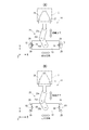
- FIG. 1A is a diagram viewed from a Y direction
- FIG. An example of an upper mast and a mast guide part is shown
- (A) is a diagram in which the mast guide part is applied to an upper mast having a square cross section
- (B) is a rectangular cross section and has increased rigidity in the transfer direction. It is the figure which applied the mast guide part to the upper mast. It is a figure which shows the state which the upper side mast and the lower side mast isolate
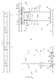
- FIG. 1 An example of the support device which supports a lower mast is shown, (A) is the figure seen from the Y direction including the support device, (B) is the figure seen from the X direction including the support device.
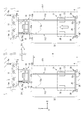
- separates an upper mast and a lower mast is shown, (A) is a figure before an upper mast and a lower mast isolate
- each direction of the X, Y, and Z directions is appropriately expressed as a direction indicated by an arrow + direction (eg, + X direction), and the opposite direction is expressed as a ⁇ direction (eg, ⁇ X direction).
- FIG. 1 is a diagram illustrating a transport system to which an overhead transport vehicle according to the present embodiment is applied.
- the transfer system 1A of the present embodiment is installed in a semiconductor device manufacturing factory, and includes a FOUP (Front Opening Unified Pod) containing a semiconductor wafer used for manufacturing a semiconductor device, or a reticle containing a processing member such as a reticle.
- the present invention is applied to a system for conveying an article 2 such as a pod.
- the article 2 is described as being a FOUP, but the article 2 may be other than the FOUP.
- the transfer system 1A can be applied to facilities other than the semiconductor field, and the article 2 may be various articles handled by the facility where the transfer system 1A is installed.
- the transport system 1 ⁇ / b> A includes a ceiling transport vehicle 3 and a track 4.
- the track 4 is a rail for traveling, and is provided in a state of being suspended from the ceiling 5 of the facility by a plurality of suspension fittings 5a.
- the overhead conveyance vehicle 3 travels along the track 4 and transfers the article 2 to the transfer destination.
- the transfer destination or transfer source of the article 2 is a load port LP of the processing device TL, a stocker (storage device, automatic warehouse) or a storage shelf RL provided in the processing device, Or the buffer ST or the like.
- the processing apparatus TL is, for example, an exposure apparatus, a coater developer, a film forming apparatus, an etching apparatus, or the like, and performs various processes on the semiconductor wafer accommodated in the article 2 transported by the transport system 1A.
- the above-described stocker stores the articles 2 transported by the transport system 1A.
- the above-described buffer ST is a side track buffer (STB), but may be an under track buffer (UTB), and is provided along the track TV while being suspended from the ceiling 5.
- the buffer ST temporarily stores the articles 2 transported by the overhead traveling vehicle VX provided in the transport system 1A.
- the overhead traveling vehicle VX is, for example, an OHT (Overhead Hoist Transport) or an OHV (Overhead Hoist Vehicle).
- the overhead traveling vehicle VX travels along the track TV provided on the ceiling 5.
- the track TV may be the same standard as the track 4, may have a junction or a branch point with the track 4, and a part or all of the track TV may be shared with the track 4.
- the overhead traveling vehicle VX includes a hoist (not shown) as one example, and the article 2 is moved up and down by the hoist so that the article 2 is placed in the load port LP of the processing apparatus TL. Deliver.
- the overhead traveling vehicle VX moves the hoist laterally along the track 4 to move the article 2 up and down, and delivers the article 2 to and from the storage shelf RL.
- One or both of the storage shelf RL and the buffer ST described above may be included in the configuration of the transfer system 1A, or may be included in equipment such as a factory where the transfer system 1A is installed.
- the overhead traveling vehicle VX may be included in the configuration of the transfer system 1A or may be included in the configuration of a transfer system different from the transfer system 1A.
- the ceiling transport vehicle 3 includes a traveling body 11, an upper mast 12, a lifting platform 13, a transfer device 14, and a lifting drive device 15.
- the traveling body 11 travels along the track 4.
- the traveling direction of the traveling body 11 is a direction substantially parallel to the track 4 (the X direction in FIG. 1).
- the traveling body 11 includes a travel drive unit (not shown) such as an electric motor, a speed reducer, an encoder, and the like.
- the traveling body 11 has a drive wheel and a driven wheel.
- the drive wheel is attached so as to be pressed against the inner upper surface of the track 4 by the elastic force of an elastic member such as a coil spring, and is connected to the output shaft of the electric motor via a reduction gear.
- the rotation of the output shaft of the electric motor is transmitted to the drive wheel through the reduction gear, and the traveling body 11 travels by the rotation of the drive wheel.
- Each of the driven wheels includes a caster, and the caster can be rotated around a caster axis in the vertical direction (Z direction) and is disposed so as to be in contact with the inner lower surface of the track 4.
- the encoder detects the rotation speed of the output shaft of the electric motor and outputs the detection result to a control unit (not shown).
- the control unit controls the rotation of the electric motor based on the detection result of the encoder, and controls the speed or stop position of the traveling body 11.
- the stop position of the traveling body 11 may be set by identifying an indicator plate or the like installed in advance along the track 4.
- a linear motor may be used as the travel drive unit.
- the upper mast 12 is attached below the traveling body 11.
- a rotating shaft 16 is provided below the traveling body 11, and an upper support 17 is attached below the rotating shaft 16.
- An upper mast 12 is attached to the upper support 17.
- the upper mast 12 is suspended from the traveling body 11.
- the upper mast 12 is provided on each side of the traveling body 11 in the traveling direction (X direction) (+ X direction ⁇ plus X-direction>, -X direction ⁇ minus X-direction>).
- a fastening member such as a bolt and a nut may be used, or welding may be used.
- the upper mast 12 includes an upper guide portion 12a for guiding an elevator 13 described later, and a connection portion 12b for connecting to a lower mast 112 described later.
- the peripheral surface of the upper mast 12 may be used, and for example, a groove portion along the longitudinal direction of the upper mast 12 may be used.
- the connecting portion 12 b is provided at the lower end portion of the upper mast 12. Moreover, the connection part 12b of the upper mast 12 and the upper end part of the lower mast 112 are detachably connected.
- the lower mast 112 has substantially the same cross section as the upper mast 12 in the direction perpendicular to the longitudinal direction, and is longer than the upper mast 12 as an example in the present embodiment.
- the lower mast 112 includes a lower guide portion 112a configured to be continuous with the upper guide portion 12a when connected to the upper mast 12.
- the lower guide 112a may be a circumferential surface of the lower mast 112, or may be a groove along the longitudinal direction of the lower mast 112, for example.
- the lower guide part 112a is provided so as to be continuous with the upper guide part 12a. That is, when the upper guide portion 12a is the peripheral surface of the upper mast 12, the peripheral surface is used as the lower guide portion 112a and is provided so as to be continuous with the upper guide portion 12a.
- the elevator 13 described later can be lowered from the upper mast 12 to the lower mast 112 and can be raised from the lower mast 112 to the upper mast 12.
- the connecting portion 12b of the upper mast 12 and the upper end portion of the lower mast 112 are combined by inserting one into the other, for example, in an inlay structure.
- the connecting portion 12b is orthogonal to the vertical direction (Z direction).
- the upper mast 12 and the lower mast 112 are connected by fixing with a pin or a fixing screw in the horizontal direction. Further, by removing the above-described pin or fixing screw, the lower mast 112 can be separated in the vertical direction from the connecting portion 12b of the upper mast 12.
- the separation of the upper mast 12 and the lower mast 112 will be described later with reference to FIG.
- the cross-sectional shape of the upper mast 12 and the cross-sectional shape of the lower mast 112 may be different. Even in this form, when the lower mast 112 is connected to the connection portion 12b, the lower guide portion 112a is provided so as to be continuous with the upper guide portion 12a.
- connection structure connection structure by a pin or a fixing screw
- connection part 12b of the upper mast 12 and the upper end part of the lower mast 112 is not limited to the above-mentioned example, Other structures may be sufficient.
- a hook may be provided on one of the upper ends of the connecting portion 12b and the lower mast 112, and a locking pin may be provided on the other.
- the lower mast 112 is fixed to the connecting portion 12b by hooking the hook on the locking pin, and the lower mast 112 can be separated from the connecting portion 12b by removing the hook from the locking pin. Separation or connection of the lower mast 112 to the connection portion 12b may be performed manually (manually) by an operator, or may be automatically performed using an actuator or the like.
- the lower mast 112 has a lower end connected to the lower support 20.
- the lower support 20 is connected to each of the + X side lower mast 112 and the ⁇ X side lower mast 112.
- the lower support 20 has a plate shape, for example.
- the traveling body 11 accelerates in the traveling direction (for example, when traveling from a stopped state), the lower portion of the lower mast 112 cannot follow the traveling body 11 due to inertial force, resulting in a delay.
- the delay in the lower portion of the lower mast 112 is caused by, for example, a travel drive unit (not shown) temporarily reducing the acceleration of the travel unit 11 or reducing such acceleration while the traveling body 11 is accelerating or traveling. It is possible to eliminate the delay in the lower portion of the lower mast 112 by repeating a plurality of times.
- the traveling drive unit temporarily increases the acceleration of the traveling unit 11 during the deceleration of the traveling body 11 or before the deceleration starts, or this increase in acceleration is repeated a plurality of times. It is possible to eliminate the lower part of the lower mast 112.
- the upper mast 12 and the lower mast 112 vibrate or swing in the traveling direction (X direction) due to the inertia acting on the lower support 20 side.
- X direction traveling direction
- the damping unit suppresses vibrations of the upper mast 12 and the like.
- the elevator 13 mounts the article 2 via a transfer device 14 to be described later, and is guided by the upper guide portion 12a of the upper mast 12 or the lower guide portion 112a of the lower mast 112 so that the upper mast 12 or lower It moves up and down along the side mast 112.
- the lifting platform 13 can be lowered from the upper mast 12 to the lower mast 112 and can be raised from the lower mast 112 to the upper mast 12.
- the elevator 13 is disposed between the + X side upper mast 12 (lower mast 112) and the -X side upper mast 12 (lower mast 112).
- the lifting platform 13 is formed, for example, with side portions fixed to both end sides of the bottom in the traveling direction of the traveling body 11.
- a transfer device 14 is attached to the upper surface of the elevator 13.
- the elevating drive device 15 elevates the elevating platform 13 along the upper mast 12 or the lower mast 112.
- the elevating drive device 15 includes a suspension member 15a and an elevating drive unit 15b.
- the hanging member 15a is a belt or a wire as one example of the present embodiment.
- the elevator 13 is suspended from the upper support 17 by the suspension member 15a.
- the raising / lowering drive part 15b is provided in the upper support body 17, and draws out and winds up the suspension member 15a.
- the lifting platform 13 is guided and lowered by the upper mast 12 or the lower mast 112 when the lifting drive unit 15b extends the suspension member. Further, when the elevating drive unit 15b winds the suspension member 15a, the elevating platform 13 is guided by the upper mast 12 or the lower mast 112 and ascends.
- the elevating drive device 15 is provided on the upper support 17 (that is, the traveling body 11), but is not limited thereto.
- the lifting drive device 15 may be provided on the lifting platform 13.
- a belt or a wire suspended from the upper support 17 is wound or fed by a device (for example, a hoist) mounted on the lifting / lowering platform 13.
- the elevator 13 may be raised and lowered.
- an electric motor or the like for driving the pinion gear is mounted on the lift 13 and a rack with which the pinion gear meshes is formed on the upper mast 12 or the lower mast 112, and the electric motor or the like is driven to rotate the pinion gear.
- the elevator 13 may be moved up and down.
- FIG. 2 shows an example of the upper mast 12 and the mast guide portions 28 and 29.
- FIG. 2A is a diagram in which the mast guide portions 28 and 29 are applied to the upper mast 12 having a square cross section.
- the transfer device 14 includes an arm unit 25 and a holding unit 26.
- the arm portion 25 has a structure in which arms 25a and 25b are connected via a joint 25c.
- the arm portion 25 expands and contracts in the horizontal direction including the Y direction when the arms 25a and 25b are bent at the joint 25c.
- the arm portion 25 has a proximal end side connected to the elevator 13 and a distal end side connected to the holding portion 26.
- the holding unit 26 has a plurality of (for example, three) pins 27 (for example, kinematic pins) used for positioning the article 2.
- the pins 27 respectively enter a plurality of radial grooves formed on the bottom surface of the article 2. In this way, this pin determines the exact position of the article 2 on the holding part 26.
- the example regarding the upper mast 12 is shown in FIG. 2, even the lower mast 112 is the same as described above.
- the transfer device 14 When the transfer device 14 receives the article 2 from the transfer source, the arm unit 25 is extended in the direction of the article 2 arranged at the transfer source, and the holding unit 26 is arranged below the bottom surface of the article 2. Then, when the elevator 13 is raised, the transfer device 14 scoops up the article 2 with the holding unit 26. In the transfer device 14, the arm unit 25 is contracted in a state where the article 2 is held on the holding unit 26, and the holding unit 26 is arranged on the lifting platform 13. Further, when transferring the article 2 to the transfer destination, the transfer device 14 positions the transfer object 14, extends the arm unit 25, and arranges the article 2 on the holding unit 26 above the transfer destination. When the lifting platform 13 is lowered, the transfer device 14 delivers the article 2 from the holding unit 26 to the transfer destination.
- the transfer device 14 shown in FIGS. 2A and 2B is an example, and other configurations may be used.
- the transfer device 14 may hold the article 2 by holding the flange 2a (see FIG. 1A) provided on the upper part of the article 2 or sandwich the side surface of the article 2 to sandwich the article 2. May be held.
- the transfer apparatus 14 is not limited to using the arm part 25 mentioned above, For example, an articulated robot arm etc. may be used.
- the direction in which the article 2 moves when the transfer device 14 performs transfer is appropriately referred to as a transfer direction.
- the expression “transfer direction” refers to a direction (Y direction) in which the arm portion 25 expands and contracts, and is orthogonal to the traveling direction (X direction) of the traveling body and also refers to the horizontal direction.
- the raising / lowering stand 13 is provided with several mast guide parts (28, 29).
- the mast guide part 28 and the mast guide part 29 are disposed so as to be able to contact the upper guide part 12a (not shown in FIG. 2) of the upper mast 12, and move up and down the elevator 13 along the upper mast 12. It is provided to make it.
- Examples of the mast guide portion 28 and the mast guide portion 29 each include a guide roller.
- the elevator 13 includes a mast guide portion 28 corresponding to each of the upper mast 12 on the + X side and the upper mast 12 on the ⁇ X side in the traveling direction of the traveling body 11 at a position above the elevator 13.
- the elevator 13 regulates the position of the movement path of the elevator 13 along the upper mast 12 in the X direction by the mast guide 28.
- the mast guide portion 28 regulates the positions of the + X side upper mast 12 and the ⁇ X side upper mast 12 with respect to the lifting platform 13.
- the relative position in the X direction between the upper mast 12 on the ⁇ X side can be restricted to a predetermined position.
- the mast guide portion 29 is perpendicular to the traveling direction of the traveling body 11 with respect to each of the upper mast 12 on the + X side and the upper mast 12 on the ⁇ X side, and the upper mast 12 is moved in the horizontal direction (transfer direction). It is provided at a sandwiching position.
- the mast guide portion 28 can prevent the upper mast 12 and the lifting platform 13 from interfering with each other, so that the lifting platform 13 can smoothly move up and down.
- the mast guide portion 29 suppresses the lifting platform 13 from shifting in the transfer direction from the position of the upper mast 12, and prevents the lifting platform 13 from moving out of the movement path along the upper mast 12.
- two mast guide portions 28 may be provided so as to sandwich each of the upper mast 12 on the + X side and the upper mast 12 on the ⁇ X side.
- each upper mast 12 is in a state surrounded by the mast guide portion 28 and the mast guide portion 29, and the lifting platform 13 can be prevented from coming off the movement path along the upper mast 12.
- the upper mast 12 has been described above, but the same applies to the lower mast 112.
- FIG. 2 (B) is a diagram showing an example in which an upper mast 102 different from the shape of the upper mast 12 shown in FIG. 2 (A) is applied.
- the upper mast 102 is orthogonal to the traveling direction of the traveling body 11 and has a higher rigidity in the horizontal direction (transfer direction, Y direction) than the rigidity of the traveling body 11 in the traveling direction (X direction).
- the rigidity in the transfer direction is the rigidity with respect to the bending moment around the axis in the direction parallel to the X direction.
- the rigidity in the traveling direction is the rigidity against the bending moment around the axis in the direction parallel to the Y direction.
- the upper mast 102 has a dimension in the Y direction that is larger than a dimension in the X direction, and the rigidity in the transfer direction is higher than the rigidity in the traveling direction.
- the lower mast 112 may also be formed with a cross-sectional shape as shown in FIG.
- the transfer device 14 receives a moment around an axis parallel to the X direction in a state where the holding unit 26 holds the article 2 and the arm unit 25 extends. This moment is transmitted to the upper mast 12 (including the lower mast 112) via the lifting platform 13. As shown in FIG. 2B, in the present embodiment, the upper mast 12 has higher rigidity in the transfer direction than that in the traveling direction. Therefore, by lowering the rigidity in the traveling direction, the upper mast 102 (lower mast 12). 112), and the upper mast 102 can withstand the bending moment applied during the transfer due to the rigidity in the transfer direction.
- the storage shelf RL has a plurality of shelf plates RLa arranged in the vertical direction, and the transfer device 14 is configured to be able to deliver the articles 2 to and from each of the plurality of shelf plates RLa.
- the transfer device 14 can also deliver the load port LP and the article 2 of the processing device TL.
- the transfer device 14 receives the article 2 from the storage shelf RL and delivers the article 2 to the load port LP.
- the transfer device 14 receives the article 2 from the load port LP and delivers the article 2 to the storage shelf RL.
- the transfer device 14 can also deliver the article 2 to the buffer ST, similarly to the load port LP.
- the weight of the ceiling transport vehicle 3 supported by the ceiling 5 is larger than the weight supported by the floor surface 6 when the traveling body 11 travels.
- the ceiling transport vehicle 3 is in non-contact with the floor surface 6 when the traveling body 11 travels (a state where it floats from the floor surface 6), and is supported by the track 4 with almost the entire weight supported by the track 4.
- the weight is almost zero.
- the driving force when the traveling body 11 travels is mainly supplied from the driving force provided by the traveling drive unit provided in the upper support part on the upper side including the upper support body 17, and the lower support body
- the lower support portion including 20 is not provided with a traveling drive unit that supplies driving force for traveling of the traveling body 11. Of the upper and lower supports, the lower support 20 moves following the upper support 17.
- the ceiling transport vehicle 3 of the present embodiment includes a fixing unit 30.
- the fixing unit 30 fixes the upper mast 12 and the lower mast 112 to the floor surface 6 of the facility when the article is transferred by the transfer device 14.
- the fixing portions 30 are anchors or the like provided on the lower support 20, and are respectively disposed at both ends of the lower support 20 in the traveling direction (X direction) and can be moved back and forth (up and down) with respect to the floor surface 6.
- the ceiling transport vehicle 3 includes a switching unit (not shown) that switches between a fixed state and a released state with respect to the lower mast 112 of the fixing unit 30. This switching part is attached to the lower support body 20, for example.
- the switching unit includes a drive source (for example, an electric motor or a cylinder device) that moves the fixed unit 30 forward and backward. By driving the drive source, the fixed state and the released state are switched.
- the aforementioned switching unit releases the fixing of the fixing unit 30 and causes the lower mast 112 to follow the traveling direction with respect to the upper mast 12.
- the switching unit described above is configured after the follow-up of the lower mast 112 with respect to the upper mast 12 (after a predetermined time has elapsed since the traveling body 11 stopped) or after the traveling body 11 has stopped.
- the lower mast 112 (the lower part of the lower mast 112) can be fixed by the fixing portion 30.
- the fixing unit 30 fixes the lower mast 112 (lower support 20)
- the relative position between the transfer destination and the lifting platform 13 is determined. Therefore, the fixing of the lower mast 112 by the fixing unit 30 is a preparation for correcting the position of the article 2 relative to the transfer destination.
- the fixing unit 30 advances toward the floor surface 6 by the switching unit when the article is transferred by the transfer device 14 and contacts the floor surface 6 to fix the lower support 20 to the floor surface 6.
- the lower mast 112 since the lower part of the lower mast 112 is connected to the lower support body 20, the lower mast 112 is fixed to the floor surface 6 together with the lower support body 20 by the fixing portion 30.
- the lower mast 112 and the lower support body 20 including the upper mast 12 are fixed to the traveling body 11 that is stopped.
- the upper mast 12 and the lower mast 112 are suspended from the traveling body 11. Therefore, after the traveling body 11 stops at the target position, when the fixing unit 30 fixes the lower part of the lower mast 112 while the upper mast 12 and the lower mast 112 are swinging or vibrating, the lower support 20 May deviate from the target stop position.
- a deviation amount from the target stop position is detected by a detection unit (not shown), and the deviation amount is corrected by a correction unit (not shown). By doing so, the position of the transfer destination with respect to the lifting platform 13 is corrected, and the transfer device 14 can accurately transfer the article 2 to the target position (transfer destination).
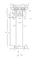
- FIG. 3 is a diagram illustrating a state where the upper mast 12 and the lower mast 112 are separated.
- the symbol La is the length of the lower structure including the lower mast 112
- the symbol Lb is the length of the upper structure including the upper mast 12.
- the length Lb of the upper structure is shorter than the length La of the lower structure.
- the upper mast 12 of the upper structure guides the elevator 13 to the upper limit in the vertical direction of the movable range of the elevator 13.
- the traveling body 11, the upper mast 12, the elevator 13, the elevator driving device 15, and the transfer device 14 are collectively expressed as an upper structure 31.
- the upper structure 31 includes a structure that is at least necessary for traveling operation, elevating operation, and transfer operation.
- the lower mast 112 and its accessories are included and expressed as a lower structure 32.
- the overhead conveyance vehicle 3 is separated into an upper structure 31 and a lower structure 32 by separating the lower mast 112 from the upper mast 12.
- the entire upper structure 31 is configured above (+ Z side) above the separation position SP where the upper mast 12 and the lower mast 112 are separated.
- the elevating drive device 15 winds the suspension member 15 a
- the elevating platform 13 moves above the lower structure 32.
- the upper structure 31 can be gathered above the separation position SP and can be easily separated from the lower structure 32.
- the upper structure 31 has various driving units integrated therein, and can be moved to another place by the traveling of the traveling body 11.
- the lower end of the lifting platform 13 is the lower end of the constituent parts of the upper structure 31 except for the upper mast 12, as shown in FIG.
- the separation position SP between the upper mast 12 and the lower mast 112 is lower than the lower end of the lifting platform 13. Therefore, in the upper structure 31, when the traveling body 11 travels in the traveling direction (X direction), the lifting platform 13 does not interfere (collision) with the lower mast 112.
- the portion 12x when the traveling body 11 travels in the traveling direction (X direction) as the portion 12x of the upper mast 12 projecting downward from the lifting platform 13 is shorter, the portion 12x has another configuration.
- the possibility of interference (collision) with an object (e.g., processing device) decreases. Therefore, the length Lx of the portion 12x, that is, the dimension (height) from the lower end (separation position SP) of the upper mast 12 to the lower end of the elevator 13 that has risen to the upper limit of the movable range is as short as possible.
- the separation position SP is set to a position closest to the lower end of the lifting platform 13 within a range in which the mast guide portions 28 and 29 (see FIG.
- the separation position SP may be set.
- the transport system 1 ⁇ / b> A of the present embodiment may include a support device 35 that supports the lower mast 112 when the lower mast 112 is separated from the upper mast 12.
- 4 shows an example of a support device 35 that supports the lower mast 112.
- FIG. 4A shows the support device 35 as viewed from the Y direction
- FIG. 4B shows the support device 35. It is the figure seen from the X direction.
- the support device 35 is disposed below the track 4 on which the traveling body 11 travels in the facility where the ceiling transport vehicle 3 is installed.
- the support device 35 includes a base 36, side portions 37, and a mast holding portion 38 as shown in FIG.
- the base 36 is installed on the floor surface 6 of the facility, and can support the lower support 20 of the ceiling transport vehicle 3.
- the base 36 can move the position of the upper surface 36a in the vertical direction by a hydraulic or pneumatic cylinder device.
- the upper surface 36a of the base 36 moves upward in a state where the lower support 20 is disposed above, and contacts the lower surface of the lower support 20 to support the lower surface side of the lower support 20.
- the side portion 37 is installed on the base 36 and extends upward on the side of the lower mast 112.
- the mast holding part 38 is attached to the side part 37.
- the mast holding part 38 holds each of the lower masts 112 from the side and holds the lower mast 112 so as not to fall down.
- the structure of the support apparatus 35 of this embodiment as shown in FIG. 4 is an example, and the structure of the support apparatus 35 can be changed suitably.
- the support device 35 may be fixed at a predetermined position, or may include a wheel or the like, and may be configured to be movable below the ceiling transport vehicle 3 stopped on the track 4, for example.
- FIG. 5 shows an operation of separating the upper mast 12 and the lower mast 112
- FIG. 5 (A) is a view before the upper mast 12 and the lower mast 112 are separated
- FIG. It is a figure after the lower mast 112 isolate
- the overhead conveyance vehicle 3 travels along the track 4 and stops above the support device 35 (separation area) as shown in FIG.
- the support apparatus 35 supports the lower support body 20 of the ceiling conveyance vehicle 3 from the downward direction by raising the upper surface 36a of the base 36.
- the support device 35 supports each of the lower masts 112 from the side by the mast holding portion 38. Then, the connection (fixation) between the upper mast 12 and the lower mast 112 is released manually or automatically, so that the lower mast 112 can be separated from the upper mast 12.
- the support device 35 moves the upper surface 36a of the base 36 downward.
- the lower mast 112 and its accessories move downward to separate the lower mast 112 from the connecting portion 12b of the upper mast 12.
- the upper structure 31 including the upper mast 12 can travel along the track 4 independently of the lower structure 32 including the lower mast 112. That is, the ceiling transport vehicle 3 (running body 11) can travel in a state where all the components for raising and lowering the lifting platform 13 are concentrated in the upper mast 12 (upper structure 31).
- the transport system 1A of the present embodiment may include the support device 35 described above, and the support device 35 may be omitted.
- the transfer system 1A may include a lifter 39 for moving the upper structure 31 separated from the lower structure 32 (lower mast 112) in the vertical direction.
- FIG. 6 is a diagram illustrating an example of the lifter 39.
- the lifter 39 is connected to the track 4 and is provided in a facility where the ceiling transport vehicle 3 is installed.
- the upper structure 31 can move to the position of the lifter 39 as the traveling body 11 travels on the track 4.
- the lifter 39 includes a lifting device (not shown) and the like, and the upper structure 31 can be removed from the track 4 and moved in the vertical direction while holding the upper structure 31.
- the lifter 39 may lower the upper structure 31 to the maintenance area MA provided on the floor surface 6 below the track 4.
- the upper structure 31 is subjected to maintenance, inspection, repair, etc. in the maintenance area MA.
- the lifter 39 may lower the upper structure 31 from the track 4 and load it on a carriage or the like.
- the upper structure 31 loaded on the carriage may be carried to another place (for example, the maintenance area MA) by the carriage.
- the lifter 39 may hold the upper structure 31 or the spare upper structure 31 for which maintenance has been completed below the track 4 and raise the upper structure 31 to connect to the track 4.
- the lifter 39 may be provided at a predetermined position, or may be provided with wheels or the like, and may be movable to the position of the upper structure 31 stopped on the track 4, for example.
- the upper structure 31 does not have to travel to the position of the lifter 39, for example, when the traveling body 11 is out of order, and other devices (for example, overhead traveling vehicles, etc.) are towed. It may be carried to the position of the lifter 39.
- FIG. 7 is a diagram showing a state where the lower mast 112 is replaced.
- the lower mast 112 (lower structure 32) supported by another support device 35A.
- the lower mast 112 can be connected to the connecting portion 12b of the upper mast 12 by moving the base 36 upward.
- the overhead conveyance vehicle 3 can attach the lower structure 32 different from the lower structure 32 isolate
- the lower mast 112 supported by the support device 35A has the same vertical length as the previously removed lower mast 112. In this configuration, by removing the lower mast 112 from the connecting portion 12b of the upper mast 12, the lower mast 112 can be easily replaced with the same lower mast 112 (lower structure 32) arranged separately.
- FIG. 8 is a diagram illustrating an example of a transport system 1B to which the ceiling transport vehicle according to the second embodiment is applied.
- 9 and 10 are diagrams illustrating the operation of the transport system 1B according to the present embodiment.
- the conveyance system 1B of the present embodiment includes a track 41, a lower mast 212 having a length different from that of the lower mast 112 described above, and a support device 42.
- the track 41 can travel on the track 41 in the same manner as the track 4.
- the track 41 is provided at a height different from the track 4 from the floor 6, and is disposed below the track 4 in FIG. 8.
- the track 41 may be attached to the ceiling 5 of the facility via a hanging metal fitting 5 a or may be attached to a pedestal formed on the floor surface 6 of the facility.
- the lower mast 212 can be connected to the connecting portion 12b of the upper mast 12 in the same manner as the lower mast 112 described above.
- the lower mast 212 is different in length in the longitudinal direction from the lower mast 112 described above, and includes a lower guide portion 212a continuous with the upper guide portion 12a of the upper mast 12.
- the lower mast 212 is shorter in the longitudinal direction than the lower mast 112 described above, and the upper end of the lower mast 212 is disposed below the upper end of the lower mast 112 described above.
- the lifter 39 is provided, for example, at a position where the track 4 and the track 41 are close to each other, and the support device 42 is disposed below the lifter 39.
- the support device 42 holds the lower structure 43 including the lower mast 212.
- the lower structure 43 is the same as the lower structure 32 described above except for the length of the lower mast 212.
- the upper structure 31 moves to the position of the lifter 39.
- the lifter 39 moves downward while holding the upper structure 31.
- the upper mast 12 and the lower mast 212 of the upper structure 31 have predetermined horizontal positions. Accordingly, as the upper structure 31 moves downward, as shown in FIG. 9, the upper end of the lower mast 212 is connected to the connecting portion 12b of the upper mast 12, and the connecting portion 12b and the lower mast are connected manually or automatically. The upper end of 212 is fixed. In this manner, the upper structure 31 and the lower structure 43 constitute the ceiling transport vehicle 3B.
- the ceiling transport vehicle 3 ⁇ / b> B can travel along the track 41 and transfer articles after the lifter 39 and the support device 35 of FIG. 9 are retracted.
- the ceiling transport vehicle 3B has a different movable range of the lifting platform 13 compared to the ceiling transport vehicle 3 (see FIG. 5A).
- the upper structure 31 including the upper mast 12 can be shared when any one of the overhead transport vehicles 3 and 3B is operated according to the height of the transfer destination.
- FIG. 11 is a diagram illustrating an example in which the upper structure 31 has moved from the storage device (stocker) ST1 to another storage device ST2.
- the ceiling transport vehicle 3 is used for transferring articles in the storage device ST1.
- the storage device ST1 includes a plurality of storage shelves on the top, bottom, left, and right in a space surrounded by side walls and the like, and the article 2 placed on a collection shelf or a loading / unloading port by the ceiling transport vehicle 3 (see FIG. 1). Is being transferred.
- the upper structure 31 separated from the lower structure 32 can pass above the side wall of the storage device ST1. . Thereby, the upper structure 31 can move along the track 4 and move to another storage device ST2.
- the lower structure 32 of the ceiling transport vehicle 3 is prepared in advance in the storage device ST2.
- the upper structure 31 can form the ceiling transport vehicle 3 in the storage device ST2 by connecting the upper mast 12 to the lower mast 112 of the lower structure 32.
- the upper structure 32 moves to one of the storage devices. It is possible to connect to the lower structure 32 prepared in the storage device, and the ceiling transport vehicle 3 for transferring the article 2 can be formed in the storage device.
- the function of the ceiling transport vehicle 3 can be secured in a plurality of storage devices by the number of upper structures 31 smaller than the number of storage devices. Moreover, since each storage apparatus should just prepare the lower structure 31, cost can be reduced. 11 shows an example in which the upper structure 31 moves above the side wall of the storage device ST1, but it can also move above the processing device TL.
- FIG. 12 is a diagram illustrating an example of the ceiling transport vehicle 3A according to the third embodiment.
- the same components as those of the above-described embodiment are denoted by the same reference numerals, and the description thereof is omitted or simplified.
- the connecting portion 18 is, for example, a hinge, and is orthogonal to the traveling direction (X direction) of the traveling body 11 and has an axis in the horizontal direction (Y direction). If the friction is neglected, the connecting portion 18 hardly transmits a moment around the axis.
- the traveling body 11 supports the upper mast 12 by a connecting portion 18 having a mechanism that is rotatable (rotatable) around an axis.
- connection portion 18 receives a moment around two directions (X direction and Z direction) perpendicular to the axis. Therefore, the connecting portion 18 prevents the upper mast 12 whose longitudinal direction is arranged in the vertical direction (Z direction) from being inclined to the side of the track 4 ( ⁇ Y side or + Y side). Further, the connecting portion 18 prevents the upper mast 12 from being twisted around the vertical direction (Z direction) when the traveling body 11 travels.
- connection part 18 contains a hinge as an example, it is not limited to it, Even if it uses the mechanism which can be rotated around a some axial center (example, X direction, Y direction) like a universal joint. Good.
- the lower end of the lower mast 112 is connected to the lower support 20 through the connection portion 19.
- the connecting portion 19 is, for example, a hinge, and has an axis that is orthogonal to the traveling direction (X direction) of the traveling body 11 and that is horizontal (Y direction).
- the connection part 19 hardly transmits the moment around the axis center, except for the influence of friction.
- the connecting portion 19 connects the lower support 20 and the lower mast 112 so as to be rotatable (rotatable) around the axis.
- connection portion 19 receives a moment around two directions (X direction and Z direction) perpendicular to the axis. Further, the connecting portion 19 prevents the lower mast 112 from being twisted around the vertical direction (Z direction) by the lower support body 20.
- connection part 19 contains a hinge as an example, it is not limited to it, Even if it uses the mechanism which can be rotated around a some axial center (example, X direction, Y direction) like a universal joint. Good.
- the upper mast 12 and the lower mast 112 are integrally rotated and tilted in the direction of the arrow due to the inertia of the lower support 20 side. Since the lower support 20 can be rotated around the axis of the connecting portion 19 of the lower mast 112, the lower mast 112 maintains a substantially horizontal state even when the lower mast 112 is inclined. In addition, since the lower support 20 moves behind or ahead of the position below the upper support 17, the ceiling transport vehicle 3 ⁇ / b> A has a parallelogram shape when the traveling body 11 is accelerated or decelerated. However, the lower support 20 can maintain a substantially horizontal state during acceleration and deceleration.
- the lifting platform 13 is formed by connecting a side portion and a bottom portion via a hinge portion 13a.
- This hinge part 13a connects the side part and bottom part of the raising / lowering stand 13 rotatably. Therefore, even when the upper mast 12 or the lower mast 112 is swung, the side portion can be rotated together with the upper mast 12 or the lower mast 112 so that the bottom portion of the lifting platform 13 can be kept horizontal.
- the lifting range of the lifting platform 13 is easy. Can be changed.
- the elevating drive device 15 is supported by the traveling body 11 even when the lower mast 112 is separated from the upper mast 12. Therefore, the upper structure 31 and the lower structure 32 can be separated by a simple operation of removing the lower masts 112 and 212 from the upper mast 12.
- the traveling body 11 and the traveling body 11 can be easily moved to other places. be able to.
- the track 4 is provided on the ceiling 5 of the equipment via the hanging metal fitting 5a.
- the track 4 may be provided directly on the ceiling 5, for example, and is formed in the vicinity of the ceiling 5, for example. It may be provided on a frame or the like.
Landscapes
- Engineering & Computer Science (AREA)
- Transportation (AREA)
- Structural Engineering (AREA)
- Mechanical Engineering (AREA)
- Civil Engineering (AREA)
- Life Sciences & Earth Sciences (AREA)
- Geology (AREA)
- Warehouses Or Storage Devices (AREA)
Abstract
【課題】マストを上側マストと下側マストとに容易に分離可能にして、分離に要する作業時間を短縮する。 【解決手段】設備の天井5側に設けられた軌道4を走行する走行体11と、走行体11の下方に取り付けられ、上側案内部12aを有する上側マスト12と、物品2を載置し、かつ、上側案内部12aに案内されて上側マスト12に沿って昇降する昇降台13と、走行体11または昇降台13に設けられて昇降台13を昇降駆動する昇降駆動装置15と、を備える、天井搬送車3であって、上側マスト12の下端に接続部12bを介して着脱自在に接続されて、上側案内部12aと連続するように成された下側案内部112aを有する下側マスト112が設けられ、昇降駆動装置15により、上側マスト12から下側マスト112に沿って昇降台13が下降可能である。
Description
本発明は、天井搬送車及び搬送システムに関する。
自動倉庫、あるいは処理装置が配置されるイントラベイなどの設備において物品を移載するため、スタッカクレーンなどが利用されている(例えば、以下の特許文献1参照)。特許文献1のスタッカクレーンは、床側の軌道に案内されて走行移動する走行体と、走行体に立設された複数本のマストと、天井側の軌道に案内される被案内部と、マストに沿って昇降する昇降台とを備える。
前記の特許文献1のスタッカクレーンでは、マストが、下側部分と上側部分とに分離及び連結自在である。メンテナンスを行うときなどにおいて、マストは、下側部分と上側部分とに分離される場合がある。昇降台を吊り下げる昇降用ベルトは、マストの上下に掛け渡されており、マストが分離される前に、スタッカクレーンから取り外される。昇降用ベルトは、昇降台を支持した状態で、昇降用ベルトの両端部が昇降台から取り外された後に、マストから引き抜かれる。その後、昇降台を降ろしてからマストを下側部分と上側部分とに分離する。
前記の特許文献1のスタッカクレーンは、メンテナンスを行うときなどにマストを分離することにより上側の構造体と下側の構造体とを分離し、この分離した上側の構造体または下側の構造体が他の場所に運ばれることがある。特許文献1のスタッカクレーンでは、マストを分離する際に、昇降用ベルトをマストから取り外す作業など、面倒な作業が必要となり、作業に時間がかかるだけでなく、その間、物品の搬送を中断する時間が長くなって搬送効率を低下させるといった問題がある。また、分離した後の上側の構造体は、昇降台を昇降させる機能がなく、物品の搬送をすることができない。
本発明は、前述の課題を考慮して、マストを上側マストと下側マストとに容易に分離可能にして、分離に要する作業時間を短縮することができ、さらに、下側マストを分離した後に昇降台を昇降させるための構成の全てを上側マストに集約した状態で走行体を走行させることが可能な天井搬送車及び搬送システムを提供することを1つの目的とする。
本発明の天井搬送車は、設備の天井側に設けられた軌道を走行する走行体と、走行体の下方に取り付けられ、上側案内部を有する上側マストと、物品を載置し、かつ、上側案内部に案内されて上側マストに沿って昇降する昇降台と、走行体または昇降台に設けられて昇降台を昇降駆動する昇降駆動装置と、を備える天井搬送車であって、上側マストの下端に接続部を介して着脱自在に接続されて、上側案内部と連続するように成された下側案内部を有する下側マストが設けられ、昇降駆動装置により、上側マストから下側マストに沿って昇降台が下降可能である。
また、上側マストの下端位置は、可動範囲の上限に配置された昇降台の下端よりも下方に設定されてもよい。また、上側マストに接続された下側マスト、及び下側マストに取り付けられる部材は、走行体の走行時に設備の床面側と非接触でもよい。また、昇降台は、上側マストまたは下側マストに沿って昇降するための複数のマストガイド部を備えてもよい。また、昇降台に設けられ、物品を移載するための移載装置を備えてもよい。
本発明の搬送システムは、前述の天井搬送車と、天井搬送車が走行する軌道と、を備える。
また、搬送システムは、上側マストとの接続を解除する際の下側マストを支持する支持装置を備えてもよい。また、搬送システムは、軌道と接続可能であり、下側マストとの接続を解除した天井搬送車を鉛直方向に移動させるリフタを備えてもよい。また、搬送システムは、上側マストの下端に接続部を介して着脱自在に接続されて、上側案内部と連続するように成された下側案内部を有し、下側マストと長さが異なる第2の下側マストを備えてもよい。
本発明の天井搬送車は、上側マストに下側マストを接続することにより、昇降台の昇降範囲を容易に拡張することができる。また、昇降駆動装置は、下側マストが上側マストから分離したときでも走行体に支持される。したがって、上側マストから下側マストを取り外すといった簡単な作業で上部構造体と下部構造体とを分離することができる。また、上側マスト、昇降台、及び昇降駆動装置が走行体に支持されてコンパクトとなるので、上側マストが下側マストから分離した後に、走行体とともに、他の場所へ容易に移動することができる。つまり、昇降台を昇降させるための構成の全てを上側マスト(上部構造体)に集約した状態で、走行体が走行できる。また、下側マストを上側マストから分離した後に、昇降台を上側マストに沿って昇降させることができる。
また、上側マストの下端位置が、可動範囲の上限に配置された昇降台の下端よりも下方に設定される例では、昇降台が可動範囲の上限に配置されたときに、上側マストの下方に昇降台の下部が突出しない。したがって、上側マストを下側マストから分離した後に走行体を移動させるときに、昇降台の下部が他の部分と干渉するのを回避できる。また、上側マストに接続された下側マスト、及び下側マストに取り付けられる部材が走行体の走行時に設備の床面側と非接触である例では、下側マストを含めた下側の構成体が床面と非接触となるので、天井搬送車の走行の負荷を低減できる。
また、昇降台が、上側マストまたは下側マストに沿って昇降するための複数のマストガイド部を備える例では、上側マストまたは下側マストに沿って昇降台を円滑に昇降させることができる。また、昇降台に設けられ、物品を移載するための移載装置を備える例では、移載装置は、物品を移載先に容易に移載できる。
また、本発明の搬送システムは、前述の天井搬送車を用いるので、上側マストのみの状態と、下側マストを接続した状態との2つの形態を選択して天井搬送車を用いることができ、天井搬送車の搬送形態の汎用性を向上させることができる。また、上側マストとの接続を解除する際の下側マストを支持する支持装置を備える例では、上側マストから分離した下側マストが倒れることを支持装置によって防止できる。
また、軌道と接続可能であり、下側マストとの接続を解除した天井搬送車を鉛直方向に移動させるリフタを備える例では、軌道と下方のメンテナンス場所との間、あるいは軌道と下方の他の軌道との間等において、下側マストを分離した天井搬送車は、リフタによって容易に昇降することができる。また、上側マストの下端に接続部を介して着脱自在に接続されて、上側案内部と連続するように成された下側案内部を有し、下側マストと長さが異なる第2の下側マストを備える例では、昇降台は、上側マストを第2の下側マストと接続することで、昇降範囲を容易に変更できる。
以下、実施形態について図面を参照しながら説明する。以下の各図において、XYZ座標系を用いて図中での方向を説明する。このXYZ座標系においては、鉛直方向(上下方向)をZ方向とし、水平方向をX方向、Y方向とする。X方向は、例えば後述する走行体の走行方向であり、Y方向は、例えば後述する移載装置の移載方向である。また、X、Y、Z方向の各方向について、適宜、矢印の指す方向+方向(例、+X方向)と表現し、その反対方向を-方向(例、-X方向)と表現する。
[第1実施形態]
図1は、本実施形態に関する天井搬送車を適用した搬送システムを示す図である。この本実施形態の搬送システム1Aは、半導体デバイスの製造工場に設置され、半導体デバイスの製造に用いられる半導体ウエハを収容したFOUP(Front Opening Unified Pod)、あるいはレチクルなどの加工用部材を収容したレチクルポッドなどの物品2を搬送するシステムに適用される。ここでは、物品2がFOUPであるとして説明するが、物品2は、FOUP以外でもよい。また、搬送システム1Aは、半導体分野以外の設備に適用可能であり、物品2は、搬送システム1Aが設置される設備で扱われる各種の物品でもよい。
図1は、本実施形態に関する天井搬送車を適用した搬送システムを示す図である。この本実施形態の搬送システム1Aは、半導体デバイスの製造工場に設置され、半導体デバイスの製造に用いられる半導体ウエハを収容したFOUP(Front Opening Unified Pod)、あるいはレチクルなどの加工用部材を収容したレチクルポッドなどの物品2を搬送するシステムに適用される。ここでは、物品2がFOUPであるとして説明するが、物品2は、FOUP以外でもよい。また、搬送システム1Aは、半導体分野以外の設備に適用可能であり、物品2は、搬送システム1Aが設置される設備で扱われる各種の物品でもよい。
搬送システム1Aは、天井搬送車3、及び軌道4を備える。例えば、本実施形態では、1つの例として、軌道4は、走行用のレールであり、設備の天井5から複数の吊り金具5aにより吊り下げられた状態で設けられる。天井搬送車3は、軌道4に沿って走行し、物品2を移載先へ移載する。例えば、本実施形態では、1つの例として、物品2の移載先あるいは移載元は、処理装置TLのロードポートLP、ストッカ(保管装置、自動倉庫)あるいは処理装置に設けられる保管棚RL、あるいはバッファSTなどである。
処理装置TLは、例えば、露光装置、コータディベロッパ、製膜装置、あるいはエッチング装置などであり、搬送システム1Aが搬送する物品2に収容された半導体ウエハに各種処理を施す。前述したストッカは、搬送システム1Aが搬送する物品2を保管する。
前述のバッファSTは、サイドトラックバッファ(STB)が示されているが、アンダートラックバッファ(UTB)であってもよく、天井5から吊り下げられた状態で軌道TVに沿って設けられる。バッファSTは、搬送システム1Aに設けられる天井走行車VXが搬送する物品2を一時的に保管する。天井走行車VXは、例えば、OHT(Overhead Hoist Transport)、あるいはOHV(Overhead Hoist Vehicle)などである。天井走行車VXは、天井5に設けられた軌道TVに沿って走行する。軌道TVは、軌道4と同じ規格であってもよいし、軌道4との合流点あるいは分岐点を有してもよく、軌道TVの一部または全部が軌道4と共通化されてもよい。
例えば、本実施形態の天井走行車VXは、1つの例として、ホイスト(図示せず)を備えており、このホイストで物品2を昇降させることによって、処理装置TLのロードポートLPに物品2の受け渡しを行う。また、天井走行車VXは、ホイストを軌道4の横方向に横出しして物品2を昇降させ、保管棚RLとの間で物品2の受け渡しを行う。前述の保管棚RL及びバッファSTの一方または双方は、搬送システム1Aの構成に含まれてもよいし、搬送システム1Aが設置される工場などの設備に含まれてもよい。また、天井走行車VXは、搬送システム1Aの構成に含まれてもよいし、搬送システム1Aとは別の搬送システムの構成に含まれてもよい。
天井搬送車3は、走行体11と、上側マスト12と、昇降台13と、移載装置14と、昇降駆動装置15と、を備える。走行体11は、軌道4に沿って走行する。走行体11の走行方向は、軌道4とほぼ平行な方向(図1ではX方向)である。走行体11は、電動モータなどの不図示の走行駆動部、減速機、エンコーダなどを有する。また、走行体11は、駆動輪及び従動輪を有する。駆動輪は、コイルスプリング等の弾性部材の弾性力により軌道4の内側上面に押し付けられるように取り付けられ、減速機を介して電動モータの出力軸に接続される。電動モータの出力軸の回転が減速機を介して駆動輪に伝えられ、駆動輪の回転により走行体11が走行する。また、従動輪は、それぞれキャスターを備えており、このキャスターは、上下方向(Z方向)のキャスター軸周りに回転可能で、かつ、軌道4の内側下面に接するように配置される。エンコーダは、電動モータの出力軸の回転数を検出し、その検出結果を制御部(図示せず)に出力する。この制御部は、エンコーダの検出結果に基づいて電動モータの回転を制御し、走行体11の速度あるいは停止位置の制御を行う。なお、走行体11の停止位置の設定は、軌道4に沿って予め設置された指標板等を識別することによって行われてもよい。また、走行駆動部は、電動モータの他に、例えば、リニアモータなどが用いられてもよい。
上側マスト12は、走行体11の下方に取り付けられている。図1において、走行体11から下方に回転軸16が設けられており、回転軸16の下方に上部支持体17が取り付けられている。上部支持体17には、上側マスト12が取り付けられている。上側マスト12は、走行体11から吊り下げられている。上側マスト12は、走行体11の走行方向(X方向)の両側(+X方向<plus X-direction>、-X方向<minus X-direction>)にそれぞれ設けられている。上部支持体17への上側マスト12の取り付けは、例えば、ボルト及びナットなどの締結部材が用いられてもよいし、溶接などが用いられてもよい。
上側マスト12は、後述する昇降台13を案内する上側案内部12aと、後述する下側マスト112に接続するための接続部12bと、を備えている。上側案内部12aは、上側マスト12の周面が用いられてもよいし、例えば、上側マスト12の長手方向に沿った溝部であってもよい。接続部12bは、上側マスト12の下端部に設けられる。また、上側マスト12の接続部12bと下側マスト112の上端部とは、着脱自在に接続される。
下側マスト112は、長手方向に直交する方向の断面が上側マスト12とほぼ同一であって、本実施形態では1つの例として、上側マスト12より長く形成されている。下側マスト112は、上側マスト12に接続したときに、上側案内部12aと連続するように成された下側案内部112aを備える。下側案内部112aは、下側マスト112の周面が用いられてもよいし、例えば、下側マスト112の長手方向に沿った溝部であってもよい。下側案内部112aは、上側案内部12aと連続するように設けられる。すなわち、上側案内部12aが上側マスト12の周面である場合、下側案内部112aとして周面が用いられ、かつ、上側案内部12aと連続するように設けられる。これにより、後述する昇降台13は、上側マスト12から下側マスト112にわたって降下可能となり、また、下側マスト112から上側マスト12にわたって上昇可能となる。
上側マスト12の接続部12bと、下側マスト112の上端部とは、例えばインロー構造のように一方を他方に挿入することで組み合わされ、例えば、この状態で上下方向(Z方向)と直交する水平方向にピンまたは固定ネジで固定することによって、上側マスト12と下側マスト112とを接続する。また、前述のピンまたは固定ネジを外すことによって、上側マスト12の接続部12bから下側マスト112が鉛直方向に分離可能になる。上側マスト12と下側マスト112との分離については、後に図3を参照して説明する。また、上側マスト12の断面形状と、下側マスト112の断面形状とが異なる形態でもよい。この形態であっても、接続部12bに下側マスト112を接続したときに、下側案内部112aが上側案内部12aと連続するように設けられる。
なお、上側マスト12の接続部12bと下側マスト112の上端部との接続構造(ピンまたは固定ネジによる接続構造)は、前述の例に限定されず、他の構造でもよい。例えば、接続部12bと下側マスト112の上端部のうち、一方にフックが設けられ、他方に係止ピンが設けられてもよい。この構成では、フックを係止ピンに掛けることで接続部12bに下側マスト112が固定され、フックを係止ピンから外すことで接続部12bから下側マスト112を分離できる。接続部12bに対する下側マスト112の分離、あるいは接続は、オペレータの手作業(手動)で行われてもよいし、アクチュエータなどを用いて自動的に行われてもよい。
下側マスト112は、その下端が、下部支持体20に接続されている。下部支持体20は、+X側の下側マスト112及び-X側の下側マスト112のそれぞれと接続されている。下部支持体20は、例えば板状である。
なお、走行体11が走行方向に加速する場合(例えば停止状態から走行を開始する場合など)、下側マスト112の下部は慣性力によって走行体11の下方に追従できず、遅れが生じてしまう。この下側マスト112の下部の遅れは、例えば、走行体11の加速中あるいは走行中に、不図示の走行駆動部が走行部11の加速度を一時的に減少させ、またはこのような加速度の減少を複数回繰り返すことで、この下側マスト112の下部の遅れを解消することが可能である。
また、走行体11が走行方向に減速する場合(例えば走行状態から停止する場合など)、下側マスト112の下部は慣性力によって走行体11の下方から前方に先行してしまう。例えば、走行体11の減速中あるいは減速を開始する前に、不図示の走行駆動部が走行部11の加速度を一時的に増加させ、またはこのような加速度の増加を複数回繰り返すことで、この下側マスト112の下部の先行を解消することが可能である。
走行体11が加速中または減速中である場合、下部支持体20側に作用する慣性によって上側マスト12及び下側マスト112が走行方向(X方向)に振動または揺動するが、天井搬送車3は、上側マスト12及び下側マスト112の振動または揺動を減衰させる減衰部を備えてもよい。この減衰部は、上側マスト12等の振動等を抑制する。
昇降台13は、後述する移載装置14を介して物品2を載置し、上側マスト12の上側案内部12aまたは下側マスト112の下側案内部112aに案内されて、上側マスト12または下側マスト112に沿って昇降する。昇降台13が、上側マスト12から下側マスト112にわたって降下可能であり、また、下側マスト112から上側マスト12にわたって上昇可能である点は前述している。昇降台13は、+X側の上側マスト12(下側マスト112)と-X側の上側マスト12(下側マスト112)との間に配置されている。昇降台13は、例えば、走行体11の走行方向における底部の両端側にそれぞれ側部が固定されて形成されている。昇降台13の上面には、移載装置14が取り付けられる。
昇降駆動装置15は、上側マスト12または下側マスト112に沿って昇降台13を昇降させる。昇降駆動装置15は、吊り下げ部材15a及び昇降駆動部15bを備える。吊り下げ部材15aは、本実施形態の1つの例として、ベルトあるいはワイヤである。昇降台13は、この吊り下げ部材15aによって上部支持体17から吊り下げられている。昇降駆動部15bは、上部支持体17に設けられ、吊り下げ部材15aの繰り出し、巻き取りを行う。昇降台13は、昇降駆動部15bが吊り下げ部材を繰り出すと、上側マスト12または下側マスト112に案内されて降下する。また、昇降台13は、昇降駆動部15bが吊り下げ部材15aを巻き取ると、上側マスト12または下側マスト112に案内されて上昇する。
昇降駆動装置15は、上部支持体17(すなわち走行体11)に設けられるが、これに限定されない。本実施形態の他の例として、昇降駆動装置15は、昇降台13に設けられてもよい。昇降台13に昇降駆動装置15が設けられる構成としては、例えば、上部支持体17から吊り下げたベルトあるいはワイヤなどを昇降台13に搭載した装置(例、ホイストなど)により巻き上げまたは繰り出しを行って昇降台13を昇降させてもよい。また、昇降台13にピニオンギアを駆動する電動モータ等が搭載され、このピニオンギアが噛み合うラックが上側マスト12または下側マスト112に形成され、電動モータ等を駆動してピニオンギアを回転させることにより昇降台13を昇降させてもよい。
図2は、上側マスト12及びマストガイド部28、29の一例を示し、図2(A)は断面が正方形状の上側マスト12にマストガイド部28、29が適用された図、図2(B)は断面が長方形状であって移載方向に剛性を高めた上側マスト102にマストガイド部28、29が適用された図である。移載装置14は、アーム部25及び保持部26を備える。アーム部25は、アーム25a、25bが関節25cを介して接続された構造である。アーム部25は、アーム25a、25bが関節25cで折り曲がることで、Y方向を含む水平方向に伸縮する。アーム部25は、基端側が昇降台13と接続され、先端側が保持部26に接続されている。保持部26は、物品2の位置決めに用いられる複数(例、3本)のピン27(例、キネマティックピン)を有している。このピン27は、物品2の底面に形成されている放射状の複数の溝部にそれぞれ入り込む。このようにして、このピンは、物品2の保持部26上での正確な位置を決定する。なお、図2では、上側マスト12に関する例を示しているが、下側マスト112であっても前述と同様である。
移載装置14が移載元から物品2を受け取るときには、アーム部25が移載元に配置された物品2の方向に伸ばされて、物品2の底面の下へ保持部26を配置する。そして、昇降台13が上昇すると、移載装置14が、保持部26で物品2をすくい上げる。そして、移載装置14は、保持部26上に物品2を保持した状態でアーム部25が縮んで、保持部26を昇降台13の上に配置する。また、移載装置14は、移載先へ物品2を渡すときには、移載先に位置決めし、アーム部25を伸ばして、保持部26上の物品2を移載先の上方に配置する。そして、昇降台13が下降すると、移載装置14は、保持部26から移載先へ物品2を渡す。
図2(A)及び図2(B)に示した移載装置14は、一例であり、他の構成でもよい。例えば、移載装置14は、物品2の上部に設けられるフランジ2a(図1(A)参照)を把持し、物品2を保持してもよいし、または物品2の側面を挟むことで物品2を保持してもよい。また、移載装置14は、前述したアーム部25を用いることに限定されず、例えば、多関節のロボットアームなどが用いられてもよい。
以下、移載装置14が移載を行う際に物品2が移動する方向を、適宜、移載方向という。本発明において、移載方向という表現は、アーム部25が伸縮する方向(Y方向)であり、走行体の走行方向(X方向)に直交し、かつ水平方向を意味する。また、図2(A)に示すように、昇降台13は、複数のマストガイド部(28、29)を備える。マストガイド部28及びマストガイド部29は、上側マスト12の上側案内部12a(図2では符号を省略している)に接触可能に配置されており、上側マスト12に沿って昇降台13を昇降させるために設けられる。マストガイド部28及びマストガイド部29の例には、それぞれガイドローラを含む。
昇降台13は、走行体11の走行方向の+X側の上側マスト12及び-X側の上側マスト12のそれぞれに対応するマストガイド部28を、昇降台13の上方の位置に備える。昇降台13は、このマストガイド28により、上側マスト12に沿った昇降台13の移動経路のX方向の位置を規制する。また、マストガイド部28は、+X側の上側マスト12及び-X側の上側マスト12のそれぞれの位置を昇降台13に対して規制するので、それにより、昇降台13が、+X側の上側マスト12と-X側の上側マスト12の間のX方向の相対位置を定められた位置に規制することができる。
マストガイド部29は、+X側の上側マスト12及び-X側の上側マスト12のそれぞれに対して、走行体11の走行方向に直交し、かつ、水平方向(移載方向)で上側マスト12を挟む位置に設けられる。マストガイド部28は、上側マスト12と昇降台13の干渉を防ぐことができるので、これにより昇降台13は、円滑な昇降を行うことができる。また、マストガイド部29は、昇降台13が上側マスト12の位置から移載方向にずれることを抑制し、昇降台13が上側マスト12に沿った移動経路から外れることを防止する。なお、より好ましい例として、マストガイド部28は、+X側の上側マスト12及び-X側の上側マスト12のそれぞれを挟むように2個ずつ設けられてもよい。これにより、各上側マスト12は、マストガイド部28及びマストガイド部29によって囲まれた状態となり、昇降台13が上側マスト12に沿った移動経路から外れるのを回避できる。また、前述では上側マスト12について説明しているが、下側マスト112についても同様である。
図2(B)は、図2(A)に示す上側マスト12の形状と異なる上側マスト102を適用した例を示す図である。この上側マスト102は、走行体11の走行方向に直交し、かつ、水平方向(移載方向、Y方向)における剛性が走行体11の走行方向(X方向)における剛性よりも高い。ここで、移載方向における剛性は、X方向に平行な方向の軸周りの曲げモーメントに対する剛性である。また、走行方向における剛性は、Y方向に平行な方向の軸周りの曲げモーメントに対する剛性である。図2(B)において、上側マスト102は、X方向の寸法に比べてY方向の寸法が大きく、移載方向における剛性が走行方向における剛性よりも高い。なお、上側マスト102が用いられる場合、下側マスト112も図2(B)に示すような断面形状で形成されてもよい。
移載装置14は、保持部26が物品2を保持してアーム部25が伸びた状態において、X方向に平行な軸周りのモーメントを受ける。このモーメントは、昇降台13を介して上側マスト12(下側マスト112を含む。)に伝わる。図2(B)のように、本実施形態では、上側マスト12は、移載方向における剛性が走行方向における剛性よりも高いので、走行方向における剛性を低くすることで上側マスト102(下側マスト112を含む)を軽量化することができ、また、移載方向における剛性によって移載時にかかる曲げモーメントに対して上側マスト102で耐えることが可能となる。
図1の説明に戻り、図1(B)の保管棚RLは、例えば、処理装置TLに対してX方向に並んだ状態で配置される。保管棚RLは、鉛直方向に配列される複数の棚板RLaを有し、移載装置14は、複数の棚板RLaのそれぞれと物品2を受け渡すことができるように構成される。また、移載装置14は、処理装置TLのロードポートLPと物品2を受け渡すことも可能である。例えば、移載装置14は、保管棚RLから物品2を受け取り、この物品2をロードポートLPへ渡す。また、移載装置14は、ロードポートLPから物品2を受け取り、この物品2を保管棚RLに渡す。また、移載装置14は、ロードポートLPと同様に、バッファSTに対して物品2を受け渡すこともできる。
天井搬送車3は、走行体11の走行時に、天井5で支持される重量が床面6で支持される重量よりも大きい。例えば、天井搬送車3は、走行体11の走行時に床面6と非接触(床面6から浮いた状態)であり、そのほぼ全重量を軌道4によって支持され、床面6で支持される重量がほぼ0である。また、本実施形態では、走行体11が走行する際の駆動力は、上部支持体17を含む上部側の上部支持部に設けられた走行駆動部による駆動力から主に供給され、下部支持体20を含む下部支持部には、走行体11の走行用の駆動力を供給する走行駆動部は設けられていない。上下の支持体のうち、下部支持体20は、上部支持体17に追従して移動する。
本実施形態の天井搬送車3は、固定部30を備える。固定部30は、移載装置14による物品の移載時に、設備の床面6に対して上側マスト12及び下側マスト112を固定する。固定部30は、下部支持体20に設けられるアンカーなどであり、下部支持体20の走行方向(X方向)の両端にそれぞれ配置され、床面6に対して進退(昇降)可能である。また、天井搬送車3は、固定部30の下側マスト112への固定状態と解除状態とを切り換える不図示の切換部を備える。この切換部は、例えば、下部支持体20に取り付けられる。また、切換部は、固定部30を進退させる駆動源(例、電動モータあるいはシリンダ装置など)を備えており、この駆動源を駆動することにより、前述の固定状態と解除状態とを切り換える。
走行体11を走行させるときには、前述の切換部は、固定部30の固定を解除して、上側マスト12に対して下側マスト112を走行方向に追従させる。走行体11を停止させたときには、前述の切換部は、上側マスト12に対する下側マスト112の追従終了後(走行体11の停止後から所定時間経過後)に、または走行体11が停止した後、直ちに下側マスト112(下側マスト112の下部)を固定部30で固定することが可能になる。なお、固定部30が下側マスト112(下部支持体20)を固定することにより、移載先と昇降台13との相対位置が決定される。したがって、固定部30による下側マスト112の固定は、物品2の移載先に対する位置補正を行うための準備である。
固定部30は、移載装置14による物品の移載時に、切換部によって床面6に向かって進出し、床面6と接触することで下部支持体20を床面6に対して固定する。こうすることで、下側マスト112の下部が、下部支持体20と接続されているので、下側マスト112は、固定部30によって下部支持体20とともに床面6に固定される。その結果、上側マスト12も含めて、下側マスト112及び下部支持体20は、停止中の走行体11に対して固定された状態となる。
前述の天井搬送車3は、上側マスト12及び下側マスト112が走行体11に対して吊り下げられている。したがって、走行体11が目標位置に停止した後に、上側マスト12及び下側マスト112が揺動または振動している状態で、固定部30が下側マスト112の下部を固定すると、下部支持体20が目標停止位置からずれる場合がある。このような場合、本実施形態の天井搬送車3では、1つの例として、不図示の検出部によって目標停止位置とのズレ量を検出し、不図示の補正部によってズレ量を補正する。こうすることで、昇降台13に対する移載先の位置補正を行い、移載装置14は、物品2を目標の位置(移載先)に正確に移載できる。
次に、上側マスト12から下側マスト112を分離する場合について説明する。図3は、上側マスト12と下側マスト112とが分離する状態を示す図である。図3において、符号Laは下側マスト112を含めた下側の構造体の長さであり、符号Lbは上側マスト12を含めた上側の構造体の長さである。上側の構造体の長さLbは、下側の構造体の長さLaよりも短い。上側の構造体のうちの上側マスト12は、昇降台13の可動範囲の、鉛直方向における上限まで昇降台13を案内する。
以下の説明において、走行体11、上側マスト12、昇降台13、昇降駆動装置15、及び移載装置14を包括して上部構造体31と表現する。上部構造体31は、走行動作、昇降動作、及び移載動作に最低限度必要な構造物を含んでいる。また、以下の説明において、下側マスト112及びその付帯物(例、下部支持体20)を含めて下部構造体32と表現する。天井搬送車3は、上側マスト12から下側マスト112が分離することによって、上部構造体31と下部構造体32とに分離される。
昇降台13が所定の高さ以上まで上昇すると、上部構造体31の全体は、上側マスト12と下側マスト112とが分離する分離位置SPよりも上方(+Z側)で構成される。例えば、昇降駆動装置15が吊り下げ部材15aを巻き取ると、昇降台13が下部構造体32よりも上方に移動する。このように、上部構造体31は、分離位置SPよりも上方に集約可能であり、下部構造体32から容易に分離できる。また、上部構造体31は、各種の駆動部が集約されており、走行体11の走行によって他の場所へ移動可能である。
昇降台13の下端は、図3に示すように、上側マスト12を除いて上部構造体31の構成部分の下端である。上側マスト12と下側マスト112との分離位置SPは、昇降台13の下端よりも下方である。したがって、上部構造体31は、走行体11が走行方向(X方向)に走行する際に、昇降台13が下側マスト112と干渉(衝突)しない。
また、上部構造体31は、上側マスト12の、昇降台13よりも下方に張り出す部分12xが短いほど、走行体11が走行方向(X方向)に走行するときに、部分12xが他の構成物(例、処理装置など)と干渉(衝突)する可能性が低下する。そのため、部分12xの長さLx、すなわち、上側マスト12の下端(分離位置SP)から、可動範囲の上限まで上昇した昇降台13の下端までの寸法(高さ)は、可能な限り短くする構成が好ましい。例えば、分離位置SPは、昇降台13のマストガイド部28、29(図2参照)が上側マスト12から外れないレベルのマージンを確保した範囲で、昇降台13の下端に最も近い位置に設定される。なお、昇降台13と一体として昇降する部材が取り付けられ、かつ、この部材が昇降台13よりも下方に配置される場合には、昇降台13の下端の代わりにこの部材の下端の位置を用いて、分離位置SPが設定されてもよい。
前述の上側マスト12と下側マスト112との分離は、下側マスト112を支持した状態で行われる。本実施形態の搬送システム1Aは、上側マスト12から下側マスト112を分離する際に、下側マスト112を支持する支持装置35を備えてもよい。図4は、下側マスト112を支持する支持装置35の一例を示し、図4(A)は支持装置35を含めてY方向から見た図、図4(B)は支持装置35を含めてX方向から見た図である。本実施形態では、1つの例として、この支持装置35は、天井搬送車3が設置される設備において、走行体11が走行する軌道4の下方に配置される。
支持装置35は、図4に示すように、ベース36、側部37、及びマスト保持部38を備える。例えば、本実施形態では、ベース36は、設備の床面6に設置され、天井搬送車3の下部支持体20を支持できる。ベース36は、本実施形態での1つの例として、油圧式または空圧式シリンダ装置によって、その上面36aの位置を鉛直方向に移動させることができる。ベース36は、その上方に下部支持体20が配置された状態で上面36aが上方に移動し、下部支持体20の下面に接触して、下部支持体20の下面側を支持する。
側部37は、ベース36上に設置され、下側マスト112の側方において上方に延びて設けられる。マスト保持部38は、側部37に取り付けられている。マスト保持部38は、下側マスト112のそれぞれを側方から把持し、下側マスト112が倒れないように保持する。なお、図4に示すような本実施形態の支持装置35の構成は一例であり、支持装置35の構成は適宜変更できる。支持装置35は、予め定められた位置に固定されていてもよいし、車輪などを備え、例えば、軌道4に停止している天井搬送車3の下方へ移動可能とする構成でもよい。
図5は、上側マスト12と下側マスト112とを分離する動作を示し、図5(A)は上側マスト12と下側マスト112とが分離する前の図、(B)は上側マスト12と下側マスト112とが分離した後の図である。天井搬送車3は、軌道4に沿って走行し、図5(A)に示すように、支持装置35の上方(分離エリア)で停止する。そして、支持装置35は、ベース36の上面36aを上昇させることで、天井搬送車3の下部支持体20を下方から支持する。さらに、支持装置35は、マスト保持部38によって、下側マスト112のそれぞれを側方から支持する。そして、上側マスト12と下側マスト112との接続(固定)が手動または自動によって解除されることにより、上側マスト12から下側マスト112が分離可能な状態になる。
次に、図5(B)に示すように、支持装置35は、ベース36の上面36aを下方に移動させる。これにより、下側マスト112及びその付帯物(例、下部支持体20)は、下方に移動して上側マスト12の接続部12bから下側マスト112が分離される。これにより、上側マスト12を含む上部構造体31は、下側マスト112を含む下部構造体32と独立して、軌道4に沿って走行可能になる。つまり、天井搬送車3(走行体11)は、昇降台13を昇降させるための構成の全てを上側マスト12(上部構造体31)に集約した状態で走行できる。なお、本実施形態の搬送システム1Aは、前述した支持装置35を備えるか否かは任意であり、支持装置35がなくてもよい。
本実施形態の他の例では、搬送システム1Aは、下部構造体32(下側マスト112)から分離された上部構造体31を鉛直方向に移動させるためのリフタ39を備えてもよい。図6は、リフタ39の一例を示す図である。リフタ39は、図6に示すように、軌道4に接続され、天井搬送車3が設置される設備に設けられる。上部構造体31は、走行体11が軌道4を走行することによって、リフタ39の位置まで移動できる。リフタ39は、不図示の昇降装置等を有しており、上部構造体31を保持したまま、上部構造体31を軌道4から外して鉛直方向に移動させることができる。例えば、本実施形態の1つの例として、リフタ39は、軌道4の下方において床面6上に設けられるメンテナンスエリアMAへ上部構造体31を下降させてもよい。上部構造体31は、メンテナンスエリアMAにおいて保守、点検、修理などが施される。
リフタ39は、上部構造体31を軌道4から下降させて台車などに積載してもよい。台車に積載された上部構造体31は、台車によって他の場所(例、メンテナンスエリアMA)等に運ばれてもよい。また、リフタ39は、メンテナンスが終了した上部構造体31、あるいは予備の上部構造体31を軌道4の下方で保持し、この上部構造体31を上昇させて軌道4に接続させてもよい。また、リフタ39は、予め定められた位置に設けられてもよいし、車輪などを備え、例えば、軌道4に停止している上部構造体31の位置へ移動可能でもよい。また、上部構造体31は、例えば走行体11が故障している場合などに、リフタ39の位置まで走行しなくてもよく、他の装置(例、天井走行車など)が牽引すること等でリフタ39の位置まで運ばれてもよい。
図7は、下側マスト112を交換した状態を示す図である。図7に示すように、上部構造体31が軌道4を移動可能になった後(図5(B)参照)、別の支持装置35Aに支持されている下側マスト112(下部構造体32)の上方まで移動し、ベース36を上方に移動させることで上側マスト12の接続部12bに別の下側マスト112を接続させることができる。これにより、天井搬送車3は、先に分離した下部構造体32とは別の下部構造体32を、異なる位置で取り付けることができる。なお、支持装置35Aに支持されている下側マスト112は、先に外した下側マスト112と鉛直方向の長さが同一である。この構成では、上側マスト12の接続部12bから下側マスト112を外すことにより、別に配置された同一の下側マスト112(下部構造体32)に容易に交換することができる。
[第2実施形態]
第2実施形態について説明する。本実施形態において、前述の実施形態と同様の構成については、同じ符号を付してその説明を省略あるいは簡略化する。図8は、第2実施形態に関する天井搬送車を適用した搬送システム1Bの一例を示す図である。図9及び図10は、本実施形態に関する搬送システム1Bの動作を示す図である。
第2実施形態について説明する。本実施形態において、前述の実施形態と同様の構成については、同じ符号を付してその説明を省略あるいは簡略化する。図8は、第2実施形態に関する天井搬送車を適用した搬送システム1Bの一例を示す図である。図9及び図10は、本実施形態に関する搬送システム1Bの動作を示す図である。
本実施形態の搬送システム1Bは、軌道41と、前述の下側マスト112と長さが異なる下側マスト212と、支持装置42と、を備える。軌道41は、軌道4と同様に走行体11が走行可能である。軌道41は、軌道4と異なる床面6からの高さに設けられ、図8では軌道4よりも下方に配置されている。軌道41は、軌道4と同様に、設備の天井5に吊り金具5aを介して取り付けられてもよいし、設備の床面6に形成された架台に取り付けられてもよい。下側マスト212は、前述の下側マスト112と同様に、上側マスト12の接続部12bと接続可能である。下側マスト212は、前述の下側マスト112と長手方向の長さが異なり、また、上側マスト12の上側案内部12aと連続する下側案内部212aを備えている。図8では、下側マスト212は、前述の下側マスト112よりも長手方向の長さが短く、下側マスト212の上端は、前述の下側マスト112の上端よりも下方に配置される。
リフタ39は、例えば、軌道4と軌道41とが近接する位置に設けられ、支持装置42は、リフタ39の下方に配置されている。支持装置42は、下側マスト212を含む下部構造体43を保持している。下部構造体43は、下側マスト212の長さ以外の点で前述の下部構造体32と同様である。
天井搬送車3は、図8の左側の図に示すように、上部構造体31と下部構造体32とに分離された後に、その上部構造体31は、リフタ39の位置へ移動する。リフタ39は、上部構造体31を保持した状態のまま、下方へ移動する。なお、上部構造体31の上側マスト12と下側マスト212とは、水平方向の位置が予め決められている。したがって、上部構造体31が下方へ移動することで、図9に示すように、上側マスト12の接続部12bに下側マスト212の上端が接続され、手動または自動によって接続部12bと下側マスト212の上端とが固定される。このようにして、上部構造体31及び下部構造体43は、天井搬送車3Bを構成する。
天井搬送車3Bは、図10に示すように、図9のリフタ39及び支持装置35が退避した後に、軌道41に沿って走行し、物品の移載を行うことができる。天井搬送車3Bは、天井搬送車3(図5(A)参照)と比べて昇降台13の可動範囲が異なる。この本実施形態の構成では、移載先の高さ等に応じて天井搬送車3、3Bのいずれかを運用するときに、上側マスト12を含めた上部構造体31を共用できる。
図11は、上部構造体31が保管装置(ストッカー)ST1から他の保管装置ST2に移動した例を示す図である。図11に示すように、天井搬送車3は、保管装置ST1内で物品の移載を行うために用いられている。保管装置ST1は、側壁等により囲まれた空間内の上下左右に複数の収容棚を備えており、天井搬送車3によって収用棚または入出庫口などに載置される物品2(図1参照)の移載を行っている。また、保管装置ST1の側壁の高さHが上側マスト12の下端よりも低い場合では、下部構造体32から切り離された上部構造体31は、保管装置ST1の側壁の上方を通過することができる。これにより、上部構造体31は、軌道4を移動して他の保管装置ST2に移動することができる。
保管装置ST2には、予め天井搬送車3の下部構造体32が準備されている。上部構造体31は、上側マスト12をこの下部構造体32の下側マスト112と接続することにより保管装置ST2内において天井搬送車3を形成することができる。なお、軌道4に沿って複数の保管装置が配置されている場合では、各保管装置にそれぞれ下部構造体32を準備しておくことにより、上部構造体32はいずれかの保管装置に移動して、その保管装置に準備されている下部構造体32と接続することが可能であり、その保管装置において物品2を移載するための天井搬送車3を形成できる。
従って、保管装置の数より少ない数の上部構造体31により複数の保管装置において天井搬送車3の機能を確保することができる。また、各保管装置は下部構造体31を準備すればよいので、コストを低減できる。なお、図11では、上部構造体31は、保管装置ST1の側壁の上方を移動する例を示しているが、処理装置TLなどの上方も移動可能である。
[第3実施形態]
第3実施形態について説明する。図12は、第3実施形態に関する天井搬送車3Aの一例を示す図である。本実施形態において、前述の実施形態と同様の構成については、同じ符号を付してその説明を省略あるいは簡略化する。図12に示すように、天井搬送車3Aは、上部支持体17に接続部18を介して上側マスト12が取り付けられている。接続部18は、例えば、ヒンジであり、走行体11の走行方向(X方向)に直交し、かつ、水平方向(Y方向)の軸心を有する。接続部18は、摩擦を無視すると、軸心の周りのモーメントをほぼ伝達しない。走行体11は、軸心の周りに回動可能(回動自在)な機構をもつ接続部18で上側マスト12を支持する。
第3実施形態について説明する。図12は、第3実施形態に関する天井搬送車3Aの一例を示す図である。本実施形態において、前述の実施形態と同様の構成については、同じ符号を付してその説明を省略あるいは簡略化する。図12に示すように、天井搬送車3Aは、上部支持体17に接続部18を介して上側マスト12が取り付けられている。接続部18は、例えば、ヒンジであり、走行体11の走行方向(X方向)に直交し、かつ、水平方向(Y方向)の軸心を有する。接続部18は、摩擦を無視すると、軸心の周りのモーメントをほぼ伝達しない。走行体11は、軸心の周りに回動可能(回動自在)な機構をもつ接続部18で上側マスト12を支持する。
また、接続部18は、軸心に垂直な2方向(X方向、Z方向)の周りのモーメントを受ける。したがって、接続部18は、長手方向が鉛直方向(Z方向)に配置された上側マスト12が軌道4の側方(-Y側あるいは+Y側)に傾くことを防止する。また、接続部18は、走行体11が走行するときに、上側マスト12が鉛直方向(Z方向)の周りにねじれることを防止する。なお、接続部18は、例としてヒンジを含むが、それには限定されず、ユニバーサルジョイントのように複数の軸心(例、X方向、Y方向)の周りで回動可能な機構を用いてもよい。
下側マスト112の下端は、接続部19を介して下部支持体20と接続されている。接続部19は、例えばヒンジであり、走行体11の走行方向(X方向)に直交し、かつ、水平方向(Y方向)の軸心を有する。接続部19は、摩擦の影響を除くと、軸心の周りのモーメントをほぼ伝達しない。接続部19は、下部支持体20と下側マスト112を軸心の周りで回動可能(回動自在)に支持する構成で接続する。
また、接続部19は、接続部18と同様に、軸心に垂直な2方向(X方向、Z方向)の周りのモーメントを受ける。また、接続部19は、下部支持体20により、下側マスト112が鉛直方向(Z方向)の周りにねじれることを防止する。なお、接続部19は、例としてヒンジを含むが、それには限定されず、ユニバーサルジョイントのように複数の軸心(例、X方向、Y方向)の周りで回動可能な機構を用いてもよい。
図12に示す天井搬送車3Aは、走行体11の加速時あるいは減速時に、下部支持体20側の慣性によって上側マスト12及び下側マスト112が一体となって矢印方向に回転して傾斜するが、下部支持体20が下側マスト112の接続部19の軸心周りに回動可能なので、下側マスト112が傾斜してもほぼ水平な状態を保持する。また、下部支持体20が上部支持体17の下方の位置より、遅れてあるいは先行して移動するので、天井搬送車3Aは、走行体11の加速時あるいは減速時において、平行四辺形状になる。しかし、加速時も減速時も下部支持体20はほぼ水平な状態を維持できる。
昇降台13は、図12に示すように、ヒンジ部13aを介して側部と底部とを接続して形成される。このヒンジ部13aは、昇降台13の側部と底部を回転可能に接続する。従って、上側マスト12または下側マスト112が揺動した場合であっても、側部が上側マスト12または下側マスト112とともに回転して昇降台13の底部を水平に維持することができる。
このように、本実施形態の天井搬送車3、3A、3B及び搬送システム1A、1Bによれば、上側マスト12に下側マスト112、212を接続することにより、昇降台13の昇降範囲を容易に変更することができる。また、昇降駆動装置15は、下側マスト112が上側マスト12から分離したときでも走行体11に支持される。したがって、上側マスト12から下側マスト112、212を取り外すといった簡単な作業で上部構造体31と下部構造体32とを分離することができる。また、上側マスト12、昇降台13、及び昇降駆動装置15が走行体11に支持されてコンパクト化されるので、下側マスト112から分離後に、走行体11とともに、他の場所へ容易に移動させることができる。
以上、実施形態について説明したが、本発明の技術範囲は、前述の実施形態などで説明した態様に限定されない。前述の実施形態などで説明した要件の1つ以上は、省略されることがある。また、前述の実施形態などで説明した要件は、適宜組み合わせることができる。また、法令で許容される限りにおいて、日本特許出願である特願2016-204184、特願2016-204185、及び本明細書において引用した全ての文献の開示を援用して本文の記載の一部とする。
また、前述の実施形態において、軌道4は、設備の天井5に吊り金具5aを介して設けられるが、例えば、天井5に直接設けられてもよく、また、例えば、天井5の近傍に形成されたフレーム(架台)などに設けられてもよい。
RL・・・保管棚
ST・・・バッファ
ST1、ST2・・・保管装置
TL・・・処理装置
TV・・・軌道
VX・・・天井走行車
1A、1B・・・搬送システム
2・・・物品
3、3A、3B・・・天井搬送車
4・・・軌道
5・・・天井
6・・・床面
11・・・走行体
12、102・・・上側マスト
12a・・・上側案内部
12b・・・接続部
13・・・昇降台
14・・・移載装置
15・・・昇降駆動装置
28、29・・・マストガイド部
36・・・ベース
39・・・リフタ
41・・・軌道
42・・・支持装置
43・・・下部構造体
44・・・マスト(第2のマスト)
112、212・・・下側マスト
112a、212a・・・下側案内部
ST・・・バッファ
ST1、ST2・・・保管装置
TL・・・処理装置
TV・・・軌道
VX・・・天井走行車
1A、1B・・・搬送システム
2・・・物品
3、3A、3B・・・天井搬送車
4・・・軌道
5・・・天井
6・・・床面
11・・・走行体
12、102・・・上側マスト
12a・・・上側案内部
12b・・・接続部
13・・・昇降台
14・・・移載装置
15・・・昇降駆動装置
28、29・・・マストガイド部
36・・・ベース
39・・・リフタ
41・・・軌道
42・・・支持装置
43・・・下部構造体
44・・・マスト(第2のマスト)
112、212・・・下側マスト
112a、212a・・・下側案内部
Claims (9)
- 設備の天井側に設けられた軌道を走行する走行体と、
前記走行体の下方に取り付けられ、上側案内部を有する上側マストと、
物品を載置し、かつ、前記上側案内部に案内されて前記上側マストに沿って昇降する昇降台と、
前記走行体または前記昇降台に設けられて前記昇降台を昇降駆動する昇降駆動装置と、を備える、天井搬送車であって、
前記上側マストの下端に接続部を介して着脱自在に接続されて、前記上側案内部と連続するように成された下側案内部を有する下側マストが設けられ、
前記昇降駆動装置により、前記上側マストから前記下側マストに沿って前記昇降台が下降可能である、天井搬送車。 - 前記上側マストの下端位置は、可動範囲の上限に配置された前記昇降台の下端よりも下方に設定される、請求項1に記載の天井搬送車。
- 前記上側マストに接続された前記下側マスト、及び前記下側マストに取り付けられる部材は、前記走行体の走行時に前記設備の床面側と非接触である、請求項1または請求項2に記載の天井搬送車。
- 前記昇降台は、前記上側マストまたは前記下側マストに沿って昇降するための複数のマストガイド部を備える、請求項1から請求項3のいずれか一項に記載の天井搬送車。
- 前記昇降台に設けられ、前記物品を移載するための移載装置を備える、請求項1から請求項4のいずれか一項に記載の天井搬送車。
- 請求項1から請求項5のいずれか一項に記載の天井搬送車と、
前記天井搬送車が走行する前記軌道と、を備える、搬送システム。 - 前記上側マストとの接続を解除する際の前記下側マストを支持する支持装置を備える、請求項6に記載の搬送システム。
- 前記軌道と接続可能であり、前記下側マストとの接続を解除した前記天井搬送車を鉛直方向に移動させるリフタを備える、請求項6または請求項7に記載の搬送システム。
- 前記上側マストの下端に接続部を介して着脱自在に接続されて、前記上側案内部と連続するように成された下側案内部を有し、前記下側マストと長さが異なる第2の下側マストを備える、請求項6から請求項8のいずれか一項に記載の搬送システム。
Priority Applications (3)
| Application Number | Priority Date | Filing Date | Title |
|---|---|---|---|
| CN201780063797.1A CN109843751B (zh) | 2016-10-18 | 2017-09-19 | 高架输送车以及输送系统 |
| US16/339,731 US10988359B2 (en) | 2016-10-18 | 2017-09-19 | Overhead transport vehicle and transport system |
| JP2018546199A JP6773123B2 (ja) | 2016-10-18 | 2017-09-19 | 搬送システム |
Applications Claiming Priority (2)
| Application Number | Priority Date | Filing Date | Title |
|---|---|---|---|
| JP2016-204185 | 2016-10-18 | ||
| JP2016204185 | 2016-10-18 |
Publications (1)
| Publication Number | Publication Date |
|---|---|
| WO2018074130A1 true WO2018074130A1 (ja) | 2018-04-26 |
Family
ID=62018401
Family Applications (1)
| Application Number | Title | Priority Date | Filing Date |
|---|---|---|---|
| PCT/JP2017/033697 Ceased WO2018074130A1 (ja) | 2016-10-18 | 2017-09-19 | 天井搬送車及び搬送システム |
Country Status (5)
| Country | Link |
|---|---|
| US (1) | US10988359B2 (ja) |
| JP (1) | JP6773123B2 (ja) |
| CN (1) | CN109843751B (ja) |
| TW (1) | TWI714809B (ja) |
| WO (1) | WO2018074130A1 (ja) |
Cited By (3)
| Publication number | Priority date | Publication date | Assignee | Title |
|---|---|---|---|---|
| WO2020154319A1 (en) * | 2019-01-22 | 2020-07-30 | Amazon Technologies, Inc. | Inventory conveyance system that transfers storage containers to and from a vertically arranged array of storage containers |
| WO2020153039A1 (ja) | 2019-01-25 | 2020-07-30 | 村田機械株式会社 | 保管システム |
| WO2020153040A1 (ja) * | 2019-01-25 | 2020-07-30 | 村田機械株式会社 | 保管システム |
Families Citing this family (10)
| Publication number | Priority date | Publication date | Assignee | Title |
|---|---|---|---|---|
| CN112173519A (zh) * | 2019-07-01 | 2021-01-05 | 上海快仓智能科技有限公司 | 控制方法和自动引导车 |
| CN112173518A (zh) * | 2019-07-01 | 2021-01-05 | 上海快仓智能科技有限公司 | 控制方法和自动引导车 |
| CN113340776A (zh) * | 2020-03-02 | 2021-09-03 | 长鑫存储技术有限公司 | 物料搬送系统、自动化天车走行区域微粒监控系统及监控方法 |
| NO346274B1 (en) * | 2020-03-30 | 2022-05-16 | Autostore Tech As | Container handling vehicle |
| KR102651030B1 (ko) * | 2021-06-08 | 2024-03-26 | 세메스 주식회사 | 반송 유닛, 물품 반송 시스템 및 반송 유닛의 제어 방법 |
| EP4361065A4 (en) * | 2021-06-24 | 2025-06-25 | Murata Machinery, Ltd. | Transport vehicle system |
| KR102883719B1 (ko) * | 2021-08-30 | 2025-11-12 | 삼성전자주식회사 | 웨이퍼 보관 시스템 |
| CN114733848B (zh) * | 2022-02-28 | 2023-05-19 | 江苏道达智能科技有限公司 | 一种amhs天车在轨清洗检测机 |
| CN116119241B (zh) * | 2023-04-17 | 2023-07-21 | 杭州慧仓信息科技有限公司 | 一种模块化仓储系统 |
| CN116692668A (zh) * | 2023-05-25 | 2023-09-05 | 亿嘉和科技股份有限公司 | 一种悬挂式空中运输小车及物料搬运方法 |
Citations (4)
| Publication number | Priority date | Publication date | Assignee | Title |
|---|---|---|---|---|
| JPH0648513A (ja) * | 1992-07-28 | 1994-02-22 | Daifuku Co Ltd | 棚設備 |
| JP2013184762A (ja) * | 2012-03-06 | 2013-09-19 | Daifuku Co Ltd | 天井搬送車の清掃装置 |
| JP5545498B2 (ja) * | 2011-12-21 | 2014-07-09 | 株式会社ダイフク | 物品保管設備及び物品保管設備におけるメンテナンス方法 |
| WO2016031352A1 (ja) * | 2014-08-26 | 2016-03-03 | 村田機械株式会社 | 仕分けシステムと仕分け方法 |
Family Cites Families (12)
| Publication number | Priority date | Publication date | Assignee | Title |
|---|---|---|---|---|
| US3445010A (en) * | 1967-07-10 | 1969-05-20 | Triax Co | Automatic warehousing system for bar storage |
| SU685569A1 (ru) * | 1974-03-06 | 1979-09-15 | Ленинградский Государственный Проектный Институт Министерства Промышленнсти Средств Связи | Устройство дл загрузки и разгрузки стеллажей склада штучными грузами |
| US5980183A (en) * | 1997-04-14 | 1999-11-09 | Asyst Technologies, Inc. | Integrated intrabay buffer, delivery, and stocker system |
| US6677690B2 (en) * | 2001-02-02 | 2004-01-13 | Asyst Technologies, Inc. | System for safeguarding integrated intrabay pod delivery and storage system |
| JP4689372B2 (ja) * | 2005-07-04 | 2011-05-25 | 株式会社日立プラントテクノロジー | スタッカクレーンの走行駆動制御方法 |
| JP5162899B2 (ja) * | 2006-12-28 | 2013-03-13 | 村田機械株式会社 | 被搬送物の保管装置 |
| CN101139869A (zh) * | 2007-08-25 | 2008-03-12 | 傅黎明 | 智能化立体仓储设备 |
| JP4807424B2 (ja) * | 2009-03-17 | 2011-11-02 | 村田機械株式会社 | 天井搬送システムと物品の移載方法 |
| JP2010247923A (ja) * | 2009-04-14 | 2010-11-04 | Murata Machinery Ltd | スタッカークレーンおよびその製造方法 |
| JP6007880B2 (ja) * | 2013-10-10 | 2016-10-12 | 株式会社ダイフク | 天井搬送車 |
| EP2990628A1 (de) * | 2014-08-28 | 2016-03-02 | Siemens Aktiengesellschaft | Bremseinrichtung für eine Gasturbine bei Lastabwurf |
| JP6766878B2 (ja) * | 2016-10-18 | 2020-10-14 | 村田機械株式会社 | スタッカクレーン |
-
2017
- 2017-09-19 US US16/339,731 patent/US10988359B2/en active Active
- 2017-09-19 CN CN201780063797.1A patent/CN109843751B/zh active Active
- 2017-09-19 WO PCT/JP2017/033697 patent/WO2018074130A1/ja not_active Ceased
- 2017-09-19 JP JP2018546199A patent/JP6773123B2/ja active Active
- 2017-10-13 TW TW106135122A patent/TWI714809B/zh active
Patent Citations (4)
| Publication number | Priority date | Publication date | Assignee | Title |
|---|---|---|---|---|
| JPH0648513A (ja) * | 1992-07-28 | 1994-02-22 | Daifuku Co Ltd | 棚設備 |
| JP5545498B2 (ja) * | 2011-12-21 | 2014-07-09 | 株式会社ダイフク | 物品保管設備及び物品保管設備におけるメンテナンス方法 |
| JP2013184762A (ja) * | 2012-03-06 | 2013-09-19 | Daifuku Co Ltd | 天井搬送車の清掃装置 |
| WO2016031352A1 (ja) * | 2014-08-26 | 2016-03-03 | 村田機械株式会社 | 仕分けシステムと仕分け方法 |
Cited By (20)
| Publication number | Priority date | Publication date | Assignee | Title |
|---|---|---|---|---|
| GB2595393A (en) * | 2019-01-22 | 2021-11-24 | Amazon Tech Inc | Inventory conveyance system that transfers storage containers to and from a vertically arranged array of storage containers |
| GB2595393B (en) * | 2019-01-22 | 2023-08-09 | Amazon Tech Inc | Inventory conveyance system that transfers storage containers to and from a vertically arranged array of storage containers |
| WO2020154319A1 (en) * | 2019-01-22 | 2020-07-30 | Amazon Technologies, Inc. | Inventory conveyance system that transfers storage containers to and from a vertically arranged array of storage containers |
| US10919747B2 (en) | 2019-01-22 | 2021-02-16 | Amazon Technologies, Inc. | Inventory conveyance system that transfers storage containers to and from a vertically arranged array of storage containers |
| EP3915901A4 (en) * | 2019-01-25 | 2022-09-28 | Murata Machinery, Ltd. | STORAGE SYSTEM |
| EP3915903A4 (en) * | 2019-01-25 | 2022-10-05 | Murata Machinery, Ltd. | STORAGE SYSTEM |
| CN113348140A (zh) * | 2019-01-25 | 2021-09-03 | 村田机械株式会社 | 保管系统 |
| KR20210106549A (ko) | 2019-01-25 | 2021-08-30 | 무라다기카이가부시끼가이샤 | 보관 시스템 |
| JPWO2020153039A1 (ja) * | 2019-01-25 | 2021-11-25 | 村田機械株式会社 | 保管システム |
| JP7136236B2 (ja) | 2019-01-25 | 2022-09-13 | 村田機械株式会社 | 保管システム |
| WO2020153040A1 (ja) * | 2019-01-25 | 2020-07-30 | 村田機械株式会社 | 保管システム |
| KR20210106550A (ko) * | 2019-01-25 | 2021-08-30 | 무라다기카이가부시끼가이샤 | 보관 시스템 |
| US11615975B2 (en) | 2019-01-25 | 2023-03-28 | Murata Machinery, Ltd. | Storage system |
| KR102531954B1 (ko) * | 2019-01-25 | 2023-05-12 | 무라다기카이가부시끼가이샤 | 보관 시스템 |
| KR102531956B1 (ko) | 2019-01-25 | 2023-05-12 | 무라다기카이가부시끼가이샤 | 보관 시스템 |
| US11673741B2 (en) | 2019-01-25 | 2023-06-13 | Murata Machinery, Ltd. | Storage system |
| WO2020153039A1 (ja) | 2019-01-25 | 2020-07-30 | 村田機械株式会社 | 保管システム |
| CN113348140B (zh) * | 2019-01-25 | 2023-08-29 | 村田机械株式会社 | 保管系统 |
| TWI828841B (zh) * | 2019-01-25 | 2024-01-11 | 日商村田機械股份有限公司 | 保管系統 |
| TWI828842B (zh) * | 2019-01-25 | 2024-01-11 | 日商村田機械股份有限公司 | 保管系統 |
Also Published As
| Publication number | Publication date |
|---|---|
| US20200047998A1 (en) | 2020-02-13 |
| TWI714809B (zh) | 2021-01-01 |
| US10988359B2 (en) | 2021-04-27 |
| CN109843751B (zh) | 2021-06-08 |
| CN109843751A (zh) | 2019-06-04 |
| JP6773123B2 (ja) | 2020-10-21 |
| JPWO2018074130A1 (ja) | 2019-07-25 |
| TW201815646A (zh) | 2018-05-01 |
Similar Documents
| Publication | Publication Date | Title |
|---|---|---|
| WO2018074130A1 (ja) | 天井搬送車及び搬送システム | |
| TWI720258B (zh) | 堆高式起重機 | |
| TWI722208B (zh) | 搬送系統 | |
| KR102509136B1 (ko) | 반송 시스템 | |
| KR102336425B1 (ko) | 반송 시스템 및 반송 방법 | |
| KR102531954B1 (ko) | 보관 시스템 | |
| KR102530860B1 (ko) | 보관 시스템 | |
| CN107055013B (zh) | 物品输送设备 | |
| JPWO2020153040A1 (ja) | 保管システム | |
| JPWO2018088089A1 (ja) | 天井搬送車、及び天井搬送車の制御方法 |
Legal Events
| Date | Code | Title | Description |
|---|---|---|---|
| 121 | Ep: the epo has been informed by wipo that ep was designated in this application |
Ref document number: 17862491 Country of ref document: EP Kind code of ref document: A1 |
|
| ENP | Entry into the national phase |
Ref document number: 2018546199 Country of ref document: JP Kind code of ref document: A |
|
| NENP | Non-entry into the national phase |
Ref country code: DE |
|
| 122 | Ep: pct application non-entry in european phase |
Ref document number: 17862491 Country of ref document: EP Kind code of ref document: A1 |