WO2018074033A1 - Siège de véhicule - Google Patents
Siège de véhicule Download PDFInfo
- Publication number
- WO2018074033A1 WO2018074033A1 PCT/JP2017/028022 JP2017028022W WO2018074033A1 WO 2018074033 A1 WO2018074033 A1 WO 2018074033A1 JP 2017028022 W JP2017028022 W JP 2017028022W WO 2018074033 A1 WO2018074033 A1 WO 2018074033A1
- Authority
- WO
- WIPO (PCT)
- Prior art keywords
- seat
- vehicle
- amount
- actuator
- change
- Prior art date
Links
- 238000001514 detection method Methods 0.000 claims description 44
- 230000037007 arousal Effects 0.000 claims description 27
- 206010062519 Poor quality sleep Diseases 0.000 claims description 24
- 230000007423 decrease Effects 0.000 claims description 14
- 238000013459 approach Methods 0.000 claims description 3
- 230000001133 acceleration Effects 0.000 description 84
- 230000029058 respiratory gaseous exchange Effects 0.000 description 9
- 239000000463 material Substances 0.000 description 6
- 239000008186 active pharmaceutical agent Substances 0.000 description 5
- 238000010586 diagram Methods 0.000 description 5
- 230000000694 effects Effects 0.000 description 3
- 238000007664 blowing Methods 0.000 description 2
- 230000001143 conditioned effect Effects 0.000 description 2
- 230000000241 respiratory effect Effects 0.000 description 2
- 238000004088 simulation Methods 0.000 description 2
- 238000012360 testing method Methods 0.000 description 2
- JOYRKODLDBILNP-UHFFFAOYSA-N Ethyl urethane Chemical compound CCOC(N)=O JOYRKODLDBILNP-UHFFFAOYSA-N 0.000 description 1
- 230000003213 activating effect Effects 0.000 description 1
- 238000004378 air conditioning Methods 0.000 description 1
- 238000004364 calculation method Methods 0.000 description 1
- 239000004744 fabric Substances 0.000 description 1
- 239000006260 foam Substances 0.000 description 1
- 239000010985 leather Substances 0.000 description 1
- 238000000034 method Methods 0.000 description 1
- 238000012986 modification Methods 0.000 description 1
- 230000004048 modification Effects 0.000 description 1
- 238000002360 preparation method Methods 0.000 description 1
- 238000003825 pressing Methods 0.000 description 1
- 238000012545 processing Methods 0.000 description 1
- 230000004044 response Effects 0.000 description 1
Images


Classifications
-
- B—PERFORMING OPERATIONS; TRANSPORTING
- B60—VEHICLES IN GENERAL
- B60N—SEATS SPECIALLY ADAPTED FOR VEHICLES; VEHICLE PASSENGER ACCOMMODATION NOT OTHERWISE PROVIDED FOR
- B60N2/00—Seats specially adapted for vehicles; Arrangement or mounting of seats in vehicles
- B60N2/02—Seats specially adapted for vehicles; Arrangement or mounting of seats in vehicles the seat or part thereof being movable, e.g. adjustable
- B60N2/0224—Non-manual adjustments, e.g. with electrical operation
- B60N2/0244—Non-manual adjustments, e.g. with electrical operation with logic circuits
-
- B—PERFORMING OPERATIONS; TRANSPORTING
- B60—VEHICLES IN GENERAL
- B60N—SEATS SPECIALLY ADAPTED FOR VEHICLES; VEHICLE PASSENGER ACCOMMODATION NOT OTHERWISE PROVIDED FOR
- B60N2/00—Seats specially adapted for vehicles; Arrangement or mounting of seats in vehicles
- B60N2/90—Details or parts not otherwise provided for
- B60N2/986—Side-rests
- B60N2/99—Side-rests adjustable
-
- B—PERFORMING OPERATIONS; TRANSPORTING
- B60—VEHICLES IN GENERAL
- B60N—SEATS SPECIALLY ADAPTED FOR VEHICLES; VEHICLE PASSENGER ACCOMMODATION NOT OTHERWISE PROVIDED FOR
- B60N2/00—Seats specially adapted for vehicles; Arrangement or mounting of seats in vehicles
- B60N2/02—Seats specially adapted for vehicles; Arrangement or mounting of seats in vehicles the seat or part thereof being movable, e.g. adjustable
- B60N2/22—Seats specially adapted for vehicles; Arrangement or mounting of seats in vehicles the seat or part thereof being movable, e.g. adjustable the back-rest being adjustable
- B60N2/2222—Seats specially adapted for vehicles; Arrangement or mounting of seats in vehicles the seat or part thereof being movable, e.g. adjustable the back-rest being adjustable the back-rest having two or more parts
-
- B—PERFORMING OPERATIONS; TRANSPORTING
- B60—VEHICLES IN GENERAL
- B60N—SEATS SPECIALLY ADAPTED FOR VEHICLES; VEHICLE PASSENGER ACCOMMODATION NOT OTHERWISE PROVIDED FOR
- B60N2/00—Seats specially adapted for vehicles; Arrangement or mounting of seats in vehicles
- B60N2/02—Seats specially adapted for vehicles; Arrangement or mounting of seats in vehicles the seat or part thereof being movable, e.g. adjustable
- B60N2/0224—Non-manual adjustments, e.g. with electrical operation
- B60N2/02246—Electric motors therefor
-
- B—PERFORMING OPERATIONS; TRANSPORTING
- B60—VEHICLES IN GENERAL
- B60N—SEATS SPECIALLY ADAPTED FOR VEHICLES; VEHICLE PASSENGER ACCOMMODATION NOT OTHERWISE PROVIDED FOR
- B60N2/00—Seats specially adapted for vehicles; Arrangement or mounting of seats in vehicles
- B60N2/02—Seats specially adapted for vehicles; Arrangement or mounting of seats in vehicles the seat or part thereof being movable, e.g. adjustable
- B60N2/0224—Non-manual adjustments, e.g. with electrical operation
- B60N2/0244—Non-manual adjustments, e.g. with electrical operation with logic circuits
- B60N2/0256—Arrangements for facilitating the occupant to get in or out of the vehicle, e.g. stowing a seat forward
-
- B—PERFORMING OPERATIONS; TRANSPORTING
- B60—VEHICLES IN GENERAL
- B60N—SEATS SPECIALLY ADAPTED FOR VEHICLES; VEHICLE PASSENGER ACCOMMODATION NOT OTHERWISE PROVIDED FOR
- B60N2/00—Seats specially adapted for vehicles; Arrangement or mounting of seats in vehicles
- B60N2/02—Seats specially adapted for vehicles; Arrangement or mounting of seats in vehicles the seat or part thereof being movable, e.g. adjustable
- B60N2/0224—Non-manual adjustments, e.g. with electrical operation
- B60N2/0244—Non-manual adjustments, e.g. with electrical operation with logic circuits
- B60N2/026—Non-manual adjustments, e.g. with electrical operation with logic circuits varying hardness or support of upholstery, e.g. for tuning seat comfort when driving curved roads
-
- B—PERFORMING OPERATIONS; TRANSPORTING
- B60—VEHICLES IN GENERAL
- B60N—SEATS SPECIALLY ADAPTED FOR VEHICLES; VEHICLE PASSENGER ACCOMMODATION NOT OTHERWISE PROVIDED FOR
- B60N2/00—Seats specially adapted for vehicles; Arrangement or mounting of seats in vehicles
- B60N2/02—Seats specially adapted for vehicles; Arrangement or mounting of seats in vehicles the seat or part thereof being movable, e.g. adjustable
- B60N2/22—Seats specially adapted for vehicles; Arrangement or mounting of seats in vehicles the seat or part thereof being movable, e.g. adjustable the back-rest being adjustable
-
- B—PERFORMING OPERATIONS; TRANSPORTING
- B60—VEHICLES IN GENERAL
- B60N—SEATS SPECIALLY ADAPTED FOR VEHICLES; VEHICLE PASSENGER ACCOMMODATION NOT OTHERWISE PROVIDED FOR
- B60N2/00—Seats specially adapted for vehicles; Arrangement or mounting of seats in vehicles
- B60N2/64—Back-rests or cushions
-
- B—PERFORMING OPERATIONS; TRANSPORTING
- B60—VEHICLES IN GENERAL
- B60N—SEATS SPECIALLY ADAPTED FOR VEHICLES; VEHICLE PASSENGER ACCOMMODATION NOT OTHERWISE PROVIDED FOR
- B60N2/00—Seats specially adapted for vehicles; Arrangement or mounting of seats in vehicles
- B60N2/64—Back-rests or cushions
- B60N2/643—Back-rests or cushions shape of the back-rests
-
- B—PERFORMING OPERATIONS; TRANSPORTING
- B60—VEHICLES IN GENERAL
- B60N—SEATS SPECIALLY ADAPTED FOR VEHICLES; VEHICLE PASSENGER ACCOMMODATION NOT OTHERWISE PROVIDED FOR
- B60N2/00—Seats specially adapted for vehicles; Arrangement or mounting of seats in vehicles
- B60N2/64—Back-rests or cushions
- B60N2/646—Back-rests or cushions shape of the cushion
-
- B—PERFORMING OPERATIONS; TRANSPORTING
- B60—VEHICLES IN GENERAL
- B60N—SEATS SPECIALLY ADAPTED FOR VEHICLES; VEHICLE PASSENGER ACCOMMODATION NOT OTHERWISE PROVIDED FOR
- B60N2/00—Seats specially adapted for vehicles; Arrangement or mounting of seats in vehicles
- B60N2/68—Seat frames
-
- B—PERFORMING OPERATIONS; TRANSPORTING
- B60—VEHICLES IN GENERAL
- B60N—SEATS SPECIALLY ADAPTED FOR VEHICLES; VEHICLE PASSENGER ACCOMMODATION NOT OTHERWISE PROVIDED FOR
- B60N2/00—Seats specially adapted for vehicles; Arrangement or mounting of seats in vehicles
- B60N2/90—Details or parts not otherwise provided for
- B60N2/986—Side-rests
-
- B—PERFORMING OPERATIONS; TRANSPORTING
- B60—VEHICLES IN GENERAL
- B60W—CONJOINT CONTROL OF VEHICLE SUB-UNITS OF DIFFERENT TYPE OR DIFFERENT FUNCTION; CONTROL SYSTEMS SPECIALLY ADAPTED FOR HYBRID VEHICLES; ROAD VEHICLE DRIVE CONTROL SYSTEMS FOR PURPOSES NOT RELATED TO THE CONTROL OF A PARTICULAR SUB-UNIT
- B60W50/00—Details of control systems for road vehicle drive control not related to the control of a particular sub-unit, e.g. process diagnostic or vehicle driver interfaces
- B60W50/08—Interaction between the driver and the control system
- B60W50/14—Means for informing the driver, warning the driver or prompting a driver intervention
- B60W50/16—Tactile feedback to the driver, e.g. vibration or force feedback to the driver on the steering wheel or the accelerator pedal
-
- B—PERFORMING OPERATIONS; TRANSPORTING
- B60—VEHICLES IN GENERAL
- B60N—SEATS SPECIALLY ADAPTED FOR VEHICLES; VEHICLE PASSENGER ACCOMMODATION NOT OTHERWISE PROVIDED FOR
- B60N2/00—Seats specially adapted for vehicles; Arrangement or mounting of seats in vehicles
- B60N2/90—Details or parts not otherwise provided for
- B60N2002/981—Warning systems, e.g. the seat or seat parts vibrates to warn the passenger when facing a danger
-
- B—PERFORMING OPERATIONS; TRANSPORTING
- B60—VEHICLES IN GENERAL
- B60W—CONJOINT CONTROL OF VEHICLE SUB-UNITS OF DIFFERENT TYPE OR DIFFERENT FUNCTION; CONTROL SYSTEMS SPECIALLY ADAPTED FOR HYBRID VEHICLES; ROAD VEHICLE DRIVE CONTROL SYSTEMS FOR PURPOSES NOT RELATED TO THE CONTROL OF A PARTICULAR SUB-UNIT
- B60W40/00—Estimation or calculation of non-directly measurable driving parameters for road vehicle drive control systems not related to the control of a particular sub unit, e.g. by using mathematical models
- B60W40/08—Estimation or calculation of non-directly measurable driving parameters for road vehicle drive control systems not related to the control of a particular sub unit, e.g. by using mathematical models related to drivers or passengers
- B60W2040/0818—Inactivity or incapacity of driver
- B60W2040/0827—Inactivity or incapacity of driver due to sleepiness
-
- B—PERFORMING OPERATIONS; TRANSPORTING
- B60—VEHICLES IN GENERAL
- B60W—CONJOINT CONTROL OF VEHICLE SUB-UNITS OF DIFFERENT TYPE OR DIFFERENT FUNCTION; CONTROL SYSTEMS SPECIALLY ADAPTED FOR HYBRID VEHICLES; ROAD VEHICLE DRIVE CONTROL SYSTEMS FOR PURPOSES NOT RELATED TO THE CONTROL OF A PARTICULAR SUB-UNIT
- B60W2540/00—Input parameters relating to occupants
- B60W2540/26—Incapacity
Definitions
- the present invention relates to a vehicle seat that can change the orientation of a seating surface to the left and right.
- a seat that can change the direction of a seating surface to the left or right is known.
- the seat surface of the seat back is provided by turning a plate-like member called a back plate or a pressure receiving member disposed between the left and right side frames of the seat back to the left or right.
- a vehicle seat that can change the direction of the vehicle to the left or right is disclosed.
- a side support driving mechanism disclosed in Patent Document 4 can be used in addition to the mechanism disclosed in Patent Document 1-3. Specifically, after the cable pulling mechanism is provided so that the left and right side support devices constituting the side support drive mechanism are driven independently, for example, the left support member is moved forward by driving the left side support device. This allows the left side of the seat back to be pushed forward. When the left side portion of the seat back is pushed forward in this way, the seat back turns right as a whole, so that the seat back can be reoriented. .
- JP 2013-049356 A JP 2013-189141 A JP2015-058794A JP 2014-189127 A
- the orientation of the seating surface of the vehicle seat can be changed according to the situation where the occupant sitting on the vehicle seat is placed.
- an object of this invention is to provide the vehicle seat which can change the direction of a seat surface according to the condition where the passenger
- Another object of the present invention is to propose various uses of a vehicle seat that can change the orientation of a seating surface.
- Another object of the present invention is to improve comfort.
- an object of this invention is to improve boarding / alighting property.
- Another object of the present invention is to enhance the arousal effect.
- Another object of the present invention is to reduce the size of an actuator for changing the orientation of a seating surface.
- Another object of the present invention is to set the amount of change in the orientation of the seat according to the passenger's preference.
- Another object of the present invention is to inform an occupant of information on the amount of change in the orientation of the seating surface that is currently set.
- a vehicle seat includes an actuator that can change the orientation of a seating surface to the left and right by moving at least a part of the seat, and a control device that controls the actuator.
- the control device includes travel posture support means for controlling the actuator to execute a seat posture in a turning direction when the vehicle turns, and the travel posture support means When the posture support control is executed, the actuator is controlled according to the position of the seat in the vehicle.
- the orientation of the seating surface can be changed according to the situation where the occupant is placed.
- the vehicle seat includes a driver seat and a second seat that is a seat other than the driver seat, and the travel posture support means executes the travel posture support control.
- the amount of change in the direction of the seating surface of the second seat may be greater than the amount of change in the direction of the seating surface of the driver seat.
- an occupant sitting in the second seat may not take a posture corresponding to the turning direction because he / she does not drive by himself / herself, but the amount of change in the orientation of the seating surface of the second seat is set to the seat of the driver seat. By making it larger than the amount of change in the direction of the surface, it is possible to satisfactorily catch the occupant sitting on the second seat when the vehicle turns. Thereby, comfort can be improved.
- the second seat includes: a passenger seat disposed on the right or left of the driver seat; and a rear seat disposed on the rear of the driver seat and the passenger seat.
- the travel posture support means when executing the travel posture support control, the amount of change in the direction of the seat surface of the rear seat is greater than or equal to the amount of change in the direction of the seat surface of the passenger seat It can be.
- the front seat is worse than the passenger seat.
- An occupant sitting in the seat can be received well on the seating surface. Thereby, comfort can be improved.
- the travel posture support means indicates the amount of change in the orientation of the seat surface when the vehicle is in an automatic driving mode in which steering is automatically performed when the travel posture support control is executed.
- the change amount of the seating direction in the automatic driving mode is the manual driving mode.
- the occupant can be satisfactorily received by the seating surface when the vehicle turns, by making it larger than the amount of change in the orientation of the seating surface. Thereby, comfort can be improved.
- the control device controls the actuator when the boarding / alighting detecting unit detects the boarding / alighting of the occupant when the boarding / alighting detecting unit detects the boarding / alighting of the vehicle. It can be set as the structure which has a boarding / alighting support means which orient
- the control device controls the actuator when the arousal state detecting means for detecting the driver's arousal state and the arousal state detecting means detect a decrease in the driver's arousal state.
- Warning means for executing warning control for changing the orientation of the seating surface, and the amount of change in the orientation of the seating surface when executing the warning control is the amount of change in the orientation of the seating surface when not executing the warning control.
- the configuration can be larger than the amount of change.
- the awakening effect can be enhanced.
- the control device controls the actuator when the arousal state detecting means for detecting the driver's arousal state and the arousal state detecting means detect a decrease in the driver's arousal state.
- Warning means for executing warning control for changing the orientation of the seating surface, and the running posture support means is an automatic driving mode in which the vehicle automatically steers when executing the running posture support control.
- the amount of change in the direction of the seating surface in a certain case is configured to be larger than the amount of change in the direction of the seating surface in the manual operation mode in which the vehicle does not automatically perform steering, and the warning control is executed.
- the change amount of the seating surface direction may be larger than the change amount of the seating surface direction when the running posture support control is executed.
- the awakening effect can be enhanced.
- the control device controls the actuator when the boarding / alighting detecting unit detects the boarding / alighting of the occupant when the boarding / alighting detecting unit detects the boarding / alighting of the vehicle.
- a warning means for executing a warning control for controlling the actuator to change the direction of the seating surface, and the amount of change in the direction of the seating surface when the boarding / alighting support control is executed is determined by the warning control. It can be set as the structure larger than the change amount of the direction of a seating surface when performing.
- the control device includes a traveling direction information acquisition unit that acquires information on a traveling direction of the vehicle, and before the vehicle turns based on the traveling direction information acquired by the traveling direction information acquisition unit. It is possible to have a structure that includes a turning notification means for notifying the occupant of turning by controlling the actuator and changing the direction of the seating surface.
- the seat has a seat central portion, and left and right seat side portions provided on the left and right sides of the seat central portion and projecting toward the occupant side from the seat central portion at a normal position, It can be set as the structure comprised so that the direction of a seat surface may be changed by moving at least one part of the said seat side part from the said normal position to the direction which approaches a passenger
- the vehicle seat includes a first support part that supports the first part of the occupant, and a second support part that supports a second part that is different from the first part of the occupant
- the actuator includes: A first actuator that changes the orientation of the seating surface of the first support portion to the left and right; and a second actuator that changes the orientation of the seating surface of the second support portion to the left and right
- the running posture support means includes the running posture support
- the control device includes a setting unit that sets a change amount of a seating surface direction based on information input by an occupant's operation
- the traveling posture support unit includes: When the change amount of the seating surface direction is set, the actuator can be controlled according to the change amount of the seating surface direction set by the setting means.
- the setting means can be configured such that the amount of change in the orientation of the seating surface can be set to any amount of change including zero.
- control device may include a display unit that displays information on the amount of change in the currently set seating direction on the display device.
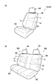
- FIG. 1 It is a figure which shows the vehicle by which the vehicle seat which concerns on one Embodiment of this invention was mounted. It is a perspective view of a vehicle seat as a vehicle seat, and is a diagram (a) showing a driver seat and a passenger seat, and a diagram (b) showing a rear seat. It is a perspective view which shows an example of the structure which changes direction of a seat surface. It is the figure which looked at the vehicle seat from the top, and is a figure (a) showing a state where a side frame is in a normal position, and a figure (b) showing a state where the right side frame rotated forward. It is a figure which shows the state which the door opened and the right side frame rotated later.
- FIG. 2 is a side view of a vehicle seat, and is a view in which the seat back is tilted backward (a), a view in which the front portion of the seat cushion is raised upward (b), and a view in which the seat back is tilted back (c).
- front and rear, left and right, and top and bottom are based on front and rear, left and right, and top and bottom of a vehicle on which a vehicle seat is mounted.
- the vehicle seat of the present embodiment is configured as a vehicle seat S mounted on a vehicle C (automobile) as an example of a vehicle.
- the vehicle seat S includes a driver seat S1 on which the driver sits and a second seat S2 that is a seat other than the driver seat S1.
- the second seat S2 includes a passenger seat S21 disposed on the left side of the driver seat S1, a rear seat S22 disposed behind the driver seat S1, and a rear seat of the passenger seat S21.
- the rear seat S23 is disposed.
- the rear seats S22 and S23 are connected and configured as an integral seat.
- the passenger seat may be arranged on the right side of the driver seat.
- the rear seats S22 and S23 may be configured as independent seats that are not connected.
- the vehicle C includes a steering wheel SW operated by a driver and an operation panel OP provided on the instrument panel. Further, on the left and right outer sides of the seats S1, S21, S22, and S23 (in this embodiment, the right side of the seats S1 and S22 and the left side of the seats S21 and S23) with respect to the left and right direction of the vehicle C, respectively, A door DR that can be opened and closed is provided. An occupant (including a driver) sitting on each of the seats S1, S21, S22, and S23 can get on and off the vehicle C from the entrance of the vehicle C by opening the left and right outer doors DR.
- the vehicle C includes an automatic driving system AS, and the automatic driving mode in which the automatic driving system AS automatically performs steering, and the automatic driving system AS does not automatically perform steering, and steering by the driver is essential.
- the manual operation mode can be executed. Switching between the automatic operation mode and the manual operation mode can be performed, for example, by the driver operating the operation panel OP.
- the automatic driving mode may be a mode in which the automatic driving system AS automatically performs steering and does not automatically accelerate and brake, or the automatic driving system AS performs at least acceleration and braking in addition to steering. A mode in which one of them is automatically performed may be used.
- each of the seats S1, S21, S22, and S23 includes a seat cushion SC, a seat back SB, and a headrest HR.
- the seat backs SB of the seats S1, S21, S22, and S23 are provided on the seat center portion 11 facing the back of the occupant and on both the left and right sides of the seat center portion 11, and are in the normal position (the position shown in FIG. 4A).
- the left and right seat side portions 12 and 13 projecting to the occupant side, more specifically to the front side, from the seat center portion 11.
- a seat cushion frame (not shown) is incorporated in the seat cushion SC.
- the seat cushion SC is configured by covering the seat cushion frame with a pad material made of urethane foam or the like and a skin material made of fabric or leather.
- the seat back SB includes a seat back frame FB.
- the seat back frame FB includes a central frame 21 that constitutes the skeleton of the seat central portion 11 and side frames 22 and 23 that constitute the skeleton of the left and right seat side portions 12 and 13.
- the left and right side frames 22 and 23 are provided so that the front end portions can swing back and forth by the rear end portions being rotatably connected to the central frame 21.
- the seat back SB is configured by covering the seat back frame FB with a pad material and a skin material.
- the actuator 30 for changing the direction of the seating surface, which is the front surface of the seatback SB, to the left and right is disposed inside the seatback SB.
- One actuator 30 is arranged on each of the left and right sides of the seat back SB corresponding to the left and right side frames 22 and 23.
- the actuator 30 rotates and moves a part of the seat back SB, specifically, the side frames 22 and 23 that are part of the seat side parts 12 and 13, thereby moving the seat back SB to the direction of the seating surface. It can be changed to right and left.
- the actuator 30 rotates and moves the side frames 22 and 23 from the normal position (see FIG. 4A) before being in the direction approaching the occupant or after being in the direction away from the occupant.
- the seat back SB is configured such that the direction of the seating surface can be changed to the left and right.
- Such an actuator 30 includes a motor 31 and a gear box 32 as an example.
- the motor 31 is, for example, a stepping motor, and is configured to be capable of forward / reverse switching of the rotation direction of the shaft.
- the gear box 32 is a member that houses a plurality of gears (not shown) for decelerating and transmitting the rotational driving force of the motor 31 to the side frames 22 and 23.
- the actuator 30 is fixed to the left and right portions of the central frame 21 by a bracket (not shown).
- the seat side portions 12 and 13 are positioned at a normal position protruding a predetermined amount from the seat center portion 11 in a non-operating state.
- the motor 31 of the right actuator 30 rotates forward and the side frame 22 moves forward from the normal position under the control of the control device 100 described later. It rotates to the front position which is the position of. Accordingly, the seat side portion 12 is pushed forward from the normal position and the front surface of the seat side portion 12 is directed to the left, so that the seating surface of the seat back SB is directed to the left as a whole.
- the motor 31 of the right actuator 30 is reversely rotated to rotate the side frame 22 from the front position shown in FIG. 4B to the normal position shown in FIG. .
- the motor 31 of the left actuator 30 is rotated forward by the control of the control device 100, and the side frame 23 is rotated from the normal position to the front position.
- the seat side portion 13 is pushed forward from the normal position and the front surface of the seat side portion 13 is directed to the right, so that the seat surface of the seat back SB is directed to the right as a whole.
- the motor 31 of the left actuator 30 is reversely rotated to rotate the side frame 23 from the front position to the normal position.
- the actuator 30 can change the orientation of the seating surface of the seat back SB left and right by rotating the side frames 22 and 23 and pushing the seat side portions 12 and 13 forward from the normal position. It is configured as follows.
- the side frames 22 and 23 are rotatable between the normal position (0) and the fifth front position (5) which is the most rotated position.
- the actuator 30 By appropriately controlling the drive time of the actuator 30 (motor 31), the actuator 30 (motor 31) can be rotated forward from the normal position to an arbitrary position between the normal position and the fifth front position.
- the first front position (1) which is a position rotated before the normal position, is rotated between the normal position and the fifth front position, and the first front position is rotated.
- the second front position (2) which is the position
- the third front position (3) which is the position rotated before the second front position, and the position rotated before the third front position.
- a fourth forward position (4) is set.
- the motor 31 of the actuator 30 on the door DR (entrance / exit DE) side is reversed by the control of the control device 100, and the side frame on the entrance / exit DE side. 22 rotates from the normal position (see the two-dot chain line) to the rear position which is the rear position.
- the front surface of the seat side portion 12 on the entrance / exit DE side is substantially flat with respect to the front surface of the seat central portion 11, so that the seating surface of the seat back SB as a whole is on the entrance / exit DE side. To be directed to.
- the vehicle seat S detects a wheel speed sensor 91 that detects a wheel speed of each wheel W, a steering angle sensor 92 that detects a steering angle of the steering wheel SW, and a driver's arousal state.
- the respiration sensor 93 is a resistance pressure sensor having a circular detection surface, and is provided between the pad material and the skin material of the seat cushion SC of the driver seat S1 (see FIG. 2A).
- the respiration sensor 93 is configured so that the electrical resistance value between the electrodes decreases as the contact resistance increases by being deformed downward according to the magnitude of the pressure applied from the upper surface.
- the respiration sensor 93 outputs an electrical signal related to this electrical resistance value to the control device 100.
- the control device 100 is configured such that the left and right actuators 30 provided on the sheets S1, S21, S22, and S23 can be individually controlled.
- the control device 100 includes a lateral acceleration acquisition means 110, a running posture support means 120, a wakefulness detection means 130, a warning means 140, a boarding / alighting detection means 150, a boarding / alighting support means 160, a setting means 170, and a display means. 180 and a storage device 190.
- the control device 100 includes a CPU (Central Processing Unit), a ROM (Read Only Memory), a RAM (Random Access Memory), and the like (not shown), and reads and executes programs stored in the storage device 190 in advance. Each of these means is realized.
- the lateral acceleration acquisition unit 110 is a unit that acquires the lateral acceleration applied to the vehicle C.
- the lateral acceleration acquisition unit 110 calculates the lateral acceleration GC by calculation based on the wheel speed acquired from the wheel speed sensor 91 and the steering angle acquired from the steering angle sensor 92.
- the lateral acceleration GC is positive on the right and negative on the left.
- the running posture support means 120 is a means for executing the running posture support control that controls the actuator 30 to turn the seating surface of the seat back SB in the turning direction when the vehicle C turns. Specifically, the running posture support means 120 drives the actuator 30 based on the lateral acceleration GC acquired by the lateral acceleration acquisition means 110 and rotates the side frames 22 and 23 to thereby seat the seat back SB. Change the orientation of the face.
- the running posture support means 120 starts running posture support control when the magnitude (absolute value) of the lateral acceleration GC is equal to or greater than the first acceleration threshold GCth1, and as shown in FIG.
- the actuator 30 is rotated forward to rotate the side frames 22 and 23 from the normal position to the first front position (1), and the seat side parts 12 and 13 are pushed forward to push the seat back SB. Turn the seat in the turning direction.
- the traveling posture support means 120 further rotates the actuator 30 in the forward direction for the driver seat S1. Then, the side frames 22 and 23 are rotated to the second front position (2), and the seat side portions 12 and 13 are pushed further forward so that the seating surface of the seat back SB is further directed in the turning direction.
- the running posture support means 120 indicates the amount of change in the orientation of the seating surface of the seat back SB, in this embodiment, the amount of rotation of the side frames 22 and 23. It is configured to be larger than when it is small. Note that the lateral acceleration GC increases when the turn is steep or the vehicle speed is high, and decreases when the turn is slow or the vehicle speed is low. Become.
- the running posture support means 120 reverses the actuator 30 to rotate the side frames 22 and 23. Then, the lateral acceleration GC is rotated back to a position before the magnitude of the lateral acceleration GC becomes equal to or greater than the second acceleration threshold value GCth2, and the direction of the seating surface of the seat back SB is slightly returned.
- the second reset threshold value Rth2 is set to a value smaller than the second acceleration threshold value GCth2 and larger than the first acceleration threshold value GCth1.
- the running posture support means 120 when the magnitude of the lateral acceleration GC becomes smaller than the first reset threshold Rth1, the running posture support means 120 further reverses the actuator 30 to rotate the side frames 22 and 23 to the normal position later, The orientation of the seating surface of the seat back SB is returned to the original, and the running posture support control is ended.
- the first reset threshold value Rth1 is set to a value smaller than the first acceleration threshold value GCth1.
- Each threshold is set in advance by a running test or simulation. Further, GCth1, GCth2, Rth1, Rth2 are set as positive values. In the present embodiment, since the lateral acceleration GC generated in the left direction as in a right turn is treated as negative, the magnitude of the lateral acceleration GC is, for example, in the case of GC ⁇ ⁇ GCth1 during the right turn. It is determined that the value is equal to or greater than one acceleration threshold value GCth1, and when GC> ⁇ Rth1, it is determined that the magnitude of the lateral acceleration GC is smaller than the first reset threshold value Rth1.
- the traveling posture support means 120 individually operates the actuators 30 of the respective sheets S1, S21, S22, S23 according to the arrangement positions of the sheets S1, S21, S22, S23 in the vehicle C when executing the traveling posture support control. It is configured to control. Specifically, when the running posture support means 120 executes the running posture support control, the amount of rotation of the side frames 22 and 23 of the second seat S2 is calculated based on the amount of rotation of the side frames 22 and 23 of the driver seat S1. Make it larger than the amount of rotation. Further, when the running posture support means 120 executes the running posture support control, the running posture support means 120 determines the amount of rotation of the side frames 22 and 23 of the rear seats S22 and S23 by rotating the side frames 22 and 23 of the passenger seat S21. Make it larger than the amount of movement.
- the running posture support means 120 rotates the side frames 22 and 23.
- the amount of movement is increased by adding 0.5 to the amount of rotation (1) of the driver's seat S1, and is rotated from the normal position to a position (1.5) intermediate between the first front position and the second front position.
- the running posture support means 120 sets the rotation amount of the side frames 22 and 23 to 0 as the rotation amount (2) of the driver seat S1. .5 is added to increase the position, and the position is rotated to an intermediate position (2.5) between the second front position and the third front position.
- the running posture support means 120 determines the amount of rotation of the side frames 22 and 23 when the lateral acceleration GC is greater than or equal to the first acceleration threshold GCth1. 1 is added to the rotation amount (1) of S1 to make it larger than the rotation amount (1.5) of the passenger seat S21, and the rotation is performed from the normal position to the second front position (2). Further, when the lateral acceleration GC is equal to or greater than the second acceleration threshold GCth2, the running posture support means 120 sets the rotation amount of the side frames 22 and 23 to the rotation amount (2) of the driver seat S1. Is added to be larger than the rotation amount (2.5) of the passenger seat S21 and is rotated to the third front position (3).
- the intermediate position between the normal position (0) and the first forward position (1) is referred to as a first intermediate position (0.5), and the first forward position (1) and the second forward position (2).
- An intermediate position between the second forward position (2) and the third forward position (3) is referred to as a third intermediate position (2.5), and the third forward position (3) and the fourth forward position (4).
- the intermediate position is referred to as a fourth intermediate position (3.5).
- An intermediate position between the fourth forward position (4) and the fifth forward position (5) is referred to as a fifth intermediate position (4.5).
- the running posture support means 120 executes the running posture support control, the amount of rotation of the side frames 22 and 23 in the automatic operation mode is changed to the side frames 22 and 23 in the manual operation mode. It is comprised so that it may become larger than the rotation amount.
- the running posture support means 120 sets the rotation amount of the side frames 22 and 23 to the rotation amount (2) in the manual operation mode. Is added to increase the rotation to the third forward position (3).
- the running posture support means 120 determines the amount of rotation of the side frames 22 and 23, The rotation amount (2) in the automatic operation mode of the driver's seat S1 is increased by adding 0.5, and is rotated from the normal position to the third intermediate position (2.5). Moreover, when the magnitude of the lateral acceleration GC becomes equal to or greater than the second acceleration threshold value GCth2, the running posture support means 120 determines the rotation amount of the side frames 22 and 23 as the rotation amount in the automatic driving mode of the driver seat S1. (3) is increased by adding 0.5 and rotated to the fourth intermediate position (3.5).
- the running posture support means 120 rotates the side frames 22 and 23. Is increased by adding 1 to the rotation amount (2) of the driver seat S1 in the automatic operation mode, and is rotated from the normal position to the third front position (3). Moreover, when the magnitude of the lateral acceleration GC becomes equal to or greater than the second acceleration threshold value GCth2, the running posture support means 120 determines the rotation amount of the side frames 22 and 23 as the rotation amount in the automatic driving mode of the driver seat S1. (1) is increased by adding 1 to (3) and rotated to the fourth forward position (4).
- the running posture support means 120 is configured to operate the actuator 30 at a slower speed when executing the running posture support control in the automatic operation mode than in the manual operation mode. Also good. According to this, since the sudden operation of the seat side portions 12 and 13 can be avoided, it is possible to suppress giving the passenger discomfort and the like.
- the arousal state detection means 130 is a means for acquiring a signal from the respiration sensor 93 and detecting the awakening state of the driver based on the signal from the respiration sensor 93.
- the wakefulness detection means 130 can determine the driver's wakefulness from the waveform of the respiratory sensor 93 as described in JP-A-2015-80521.
- a signal indicating that is provided. Output to warning means 140.
- the warning means 140 executes warning control for controlling the actuator 30 of the driver's seat S1 to change the seating direction of the seat back SB when the wakefulness detection means 130 detects a decrease in the driver's wakefulness. It is means to do. Specifically, the warning means 140 starts warning control when the wakefulness detection means 130 detects a decrease in the driver's wakefulness, and alternately forward and reverse the left and right actuators 30 of the driver seat S1. Thus, the side frames 22 and 23 are alternately rotated back and forth to change the orientation of the seating surface of the seat back SB alternately left and right.
- the warning means 140 first rotates the right actuator 30 forward to rotate the side frame 22 forward from the normal position to the fifth front position (5), and pushes the seat side part 12 forward.
- the seating surface of the seatback SB is turned to the left, and then the right actuator 30 is reversed to rotate the side frame 22 backward from the fifth front position (5) to the normal position.
- the warning means 140 rotates the left actuator 30 forward to rotate the side frame 23 forward from the normal position to the fifth forward position (5), and pushes out the seat side 13 forward to seat back.
- the seat surface of the seat back SB is turned to the right, and then the left actuator 30 is reversed to rotate the side frame 23 back from the fifth front position (5) to the normal position. return.
- the warning unit 140 repeats this series of operations in the warning control. Thereby, the warning means 140 tries to awaken the driver by swinging the upper body of the driver left and right.
- the amount of rotation of the side frames 22 and 23 when the warning control is executed is set to be larger than the amount of rotation of the side frames 22 and 23 when the warning control is not executed.
- the amount of rotation of the side frames 22 and 23 when executing the warning control is larger than the amount of rotation of the side frames 22 and 23 when the vehicle C executes the running posture support control.
- the amount of rotation (5) of the side frames 22 and 23 when executing the warning control is determined when the running posture support control is executed when the vehicle C is in the automatic driving mode. It is larger than the amount of rotation of the side frames 22 and 23 (3 at the maximum).
- the warning unit 140 may be configured to operate the actuator 30 at a faster speed when executing the warning control than when executing the driving posture support control by the driving posture support unit 120. For example, if the running posture support means 120 operates the actuator 30 at a speed that is 80% of the capacity of the actuator 30, the warning means 140 can be configured to operate the actuator 30 at a speed of 100%.
- the boarding / alighting detection means 150 is a means for detecting boarding / alighting of a passenger on the vehicle C.
- the getting-on / off detection unit 150 acquires a signal from the opening / closing detection sensor 94 that detects opening / closing of the door DR, and detects that the door DR has been opened based on the signal from the opening / closing detection sensor 94. It is determined that there is a passenger getting on and off the vehicle C.
- the boarding / alighting detection unit 150 determines that there is a boarding / alighting of the occupant on the vehicle C, the boarding / alighting detection unit 150 outputs a signal indicating this to the boarding / alighting support unit 160.
- the boarding / alighting support means 160 controls the actuator 30 on the boarding / alighting side of the seats S1, S21, S22, S23 to control the seating surface of the seatback SB. It is a means for executing boarding / alighting support control directed toward the boarding / alighting side of the vehicle C.
- the boarding / alighting support means 160 detects that the door DR is opened by the boarding / alighting detection means 150, as shown in FIG. 5, the boarding / alighting gate DE side of the vehicle seat S corresponding to the opened door DR.
- the side frames 22 and 23 are rotated from the normal position to the rear position by rotating the actuator 30 in the reverse direction so that the seating surface of the seat back SB faces the entrance / exit DE.
- the boarding / alighting support means 160 detects that the door DR is closed by the boarding / alighting detection means 150, the boarding / alighting support means 160 causes the actuator 30 on the boarding gate DE side of the vehicle seat S corresponding to the closed door DR to rotate forward.
- the frames 22 and 23 are rotated from the rear position to the normal position, and the direction of the seating surface of the seat back SB is restored.
- the amount of rotation from the normal position to the rear position of the side frames 22 and 23 when executing the getting-on / off support control is fifth from the normal position of the side frames 22 and 23 when executing the warning control. It is set to be larger than the amount of rotation to the front position. For this reason, the change amount of the seating surface direction of the seat back SB when executing the getting on / off support control is larger than the change amount of the seating surface direction of the seat back SB when executing the warning control.
- the setting means 170 is a means for setting the amount of change in the seating surface direction of the seat back SB based on information input by an occupant's operation. Can be set. Specifically, the setting means 170 is configured to be able to set the amount of rotation of the side frames 22 and 23 for each of the seats S1, S21, S22, and S23 based on information input by the occupant operating the operation panel OP. Has been. The amount of rotation of the side frames 22 and 23 can be set as the amount of rotation from the normal position to an arbitrary position between the normal position and the fifth front position (5).
- the traveling posture support unit 120 when the setting unit 170 sets the amount of rotation of the side frames 22 and 23 (the amount of change in the orientation of the seating surface of the seat back SB), the traveling posture support unit 120 is set by the setting unit 170.
- the actuator 30 is controlled according to the set rotation amount. That is, when the setting unit 170 sets the rotation amounts of the side frames 22 and 23, the traveling posture support unit 120 controls the actuator 30 with priority on the set rotation amount.
- the running posture support unit 120 does not change the side acceleration GC even when the lateral acceleration GC is greater than or equal to the first acceleration threshold GCth1.
- the part frames 22 and 23 are not rotated (the actuator 30 is not driven) and maintained at the normal position.
- the traveling posture support means 120 maintains the normal position without driving the actuator 30 even when the magnitude of the lateral acceleration GC becomes equal to or greater than the second acceleration threshold GCth2. That is, when the setting unit 170 sets the rotation amount to 0, the traveling posture support unit 120 does not execute the traveling posture support control (turns OFF).
- the traveling posture support unit 120 has a lateral acceleration GC magnitude.
- the first acceleration threshold value GCth1 or more is reached, the side frames 22 and 23 are moved from the normal position to the third position from the normal position by the rotation amount (3) set by the setting means 170 instead of the normal rotation amount (1) shown in FIG. Rotate to the forward position.
- the magnitude of the lateral acceleration GC becomes equal to or greater than the second acceleration threshold GCth2
- the running posture support means 120 maintains the third front position without rotating the side frames 22 and 23.
- the setting unit 170 determines the orientation of the seat surface when the lateral acceleration GC is greater than or equal to the first acceleration threshold GCth1 and when the lateral acceleration GC is greater than or equal to the second acceleration threshold GCth2.
- the amount of change may be individually settable.
- the warning unit 140 and the boarding / alighting support unit 160 are configured not to execute the control (set to OFF) when the setting unit 170 prohibits the execution of the warning control or the boarding / alighting support control by an occupant's operation. Also good.
- the display unit 180 is a unit that displays information on the amount of change in the seating surface orientation of the seatback SB that is currently set on the display screen DS of the operation panel OP as a display device. Specifically, the display unit 180 displays the change amount set by the setting unit 170 on the display screen DS of the operation panel OP when the setting unit 170 sets the change amount of the seating direction. When the setting unit 170 does not set the amount of change in the seating direction, the display unit 180 may display the setting value of the running posture support control on the display screen DS of the operation panel OP. It does not have to be displayed. Further, instead of the set value, the fact that the running posture support control is to be executed (that is, ON) may be displayed on the display screen DS of the operation panel OP.
- the storage device 190 is a device that stores values acquired from the sensors 91 to 94, values calculated by each means, threshold values, setting values, and the like.
- a lateral acceleration GC is generated in the vehicle C.
- the running posture support means 120 runs running posture support control that directs the seating surface of the seat back SB of each of the seats S1, S21, S22, S23 in the turning direction. Execute.
- the right actuator 30 when the vehicle is turning left, the right actuator 30 is rotated forward to move the side frame 22 from the normal position, and when the driver's seat S1, the first front position (1 ), In the case of the passenger seat S21, it is rotated to the second intermediate position (1.5), and in the case of the rear seats S22 and S23, it is rotated to the second front position (2), and the seat side portion 12 is pushed forward to seat. Turn the seat of the back SB to the left. If the vehicle is turning right, the left actuator 30 is rotated forward to move the side frame 23 from the normal position to the first front position (1), the second intermediate position (1.5), or the second front position. Rotate to (2), push the seat side portion 13 forward, and turn the seat back SB rightward.
- the traveling posture support means 120 further rotates the right actuator 30 in the forward direction when the vehicle is turning counterclockwise to move the side frame 22 to the second front position when the driver seat S1.
- the front seat S21 is rotated to the third intermediate position (2.5), and the rear seats S22 and S23 are rotated to the third front position (3) to move the seat side portion 12 further forward. Push out and turn the seat back of the seat back SB further to the left.
- the left actuator 30 is further rotated forward so that the side frame 23 moves to the second front position (2), the third intermediate position (2.5), or the third front position (3 ), The seat side portion 13 is pushed further forward, and the seat surface of the seat back SB is further directed to the right.
- the upper body of the occupant can be satisfactorily received by the seat surface of the seat back SB.
- the distance between the steering wheel SW and the seat back SB can be shortened by pushing the end of the seat back SB opposite to the left and right sides in the turning direction, thereby facilitating steering. it can.
- the running posture support means 120 reverses the actuator 30 to the side portion.
- the frames 22 and 23 are rotated back to the first front position (1), the second intermediate position (1.5), or the second front position (2), and the orientation of the seating surface of the seat back SB is slightly returned (see FIG. 8).
- the running posture support means 120 further reverses the actuator 30 and moves the side frames 22, 23 back to the normal position. Rotate to return the seating surface of the seat back SB to the original orientation (see FIG. 1).
- the arousal state detection unit 130 is based on the signal acquired from the respiration sensor 93 and the awakening state. Calculate the value indicating. Then, when it is determined that the value indicating the arousal state satisfies a predetermined arousal state threshold value and the driver's arousal state is lower than a predetermined reference, a signal indicating that is output to the warning unit 140.
- the warning means 140 executes warning control for changing the orientation of the seating surface of the seat back SB of the driver seat S1 in response to this signal.
- FIGS. 10A to 10D are repeated. That is, as shown in FIG. 10A, first, the right actuator 30 is rotated forward to rotate the side frame 22 forward from the normal position to the fifth front position (5), and the seat side portion 12 is moved. Push forward and turn the seat back SB left. Thereafter, as shown in FIG. 10B, the right actuator 30 is reversely rotated to return the seating surface of the seat back SB to the original direction. Next, as shown in FIG. 10C, the left actuator 30 is rotated forward to rotate the side frame 23 forward from the normal position to the fifth front position (5), and the seat side 13 is moved forward. And the seat surface of the seat back SB is directed to the right. Thereafter, as shown in FIG. 10D, the left actuator 30 is reversely rotated to return the seating surface of the seat back SB to the original direction. By repeating this series of operations, the upper body of the driver can be greatly swung left and right, so that the driver can be awakened.
- the driving posture support means 120 executes the driving posture support control when the driver is turning, and in such a case, the driver's arousal state may be reduced. The nature is low. For this reason, there are few situations where the running posture support control by the running posture support means 120 interferes with the warning control by the warning means 140. If the operating condition of the running posture support control and the operating condition of the warning control are satisfied at the same time, it may be configured to give priority to any control, for example, the running posture support control.
- the boarding / alighting support means 160 places the seat back SB of the corresponding seat S1, S21, S22, S23 on the vehicle.
- the boarding / alighting support control for the C side of the boarding / alighting gate DE is executed. Specifically, for example, when the door DR of the driver seat S1 is opened, the boarding / alighting support means 160 reverses the right actuator 30 to move the side frame 22 backward from the normal position as shown in FIG.
- the seat back SB is turned to the position, and the seat surface of the seat back SB is directed to the entrance / exit DE.
- the boarding / alighting support means 160 rotates the right actuator 30 in the normal direction to rotate the side frame 22 from the rear position to the normal position, thereby seating the seat back SB. Restore the orientation of the face.
- the direction of the seating surface of the seat back SB is appropriate depending on the situation in which the occupant is placed, specifically the arrangement position of the seats S1, S21, S22, S23 in the vehicle C. Can be changed. Accordingly, when the vehicle C turns, the occupant can be appropriately supported by the seat surface of the seat back SB according to the situation in which the vehicle C is placed.
- the occupant sitting on the second seat S2 does not drive by himself / herself, the occupant may not take a posture corresponding to the turning direction. Since it is larger than the seat S1, an occupant sitting on the second seat S2 can be satisfactorily received by the seat surface of the seat back SB when the vehicle C turns. Thereby, comfort can be improved.
- the change amount of the seating direction of the rear seats S22, S23 is made larger than the change amount of the seating direction of the passenger seat S21, the rear seat S22 whose front view is worse than that of the passenger seat S21. , S23 can be satisfactorily received by the seat surface of the seat back SB. Thereby, comfort can be improved.
- the amount of change in the seating surface direction of the seat back SB during the automatic operation mode is made larger than that during the manual operation mode, the situation where the occupant is placed in the seating surface direction of the seat back SB, specifically, the vehicle It can be changed according to the operation mode of C.
- the driver does not steer and may not be able to take a posture corresponding to the turning direction.
- the amount of change in the direction of the seating surface of the seat back SB in the automatic driving mode is changed to the manual driving mode.
- the vehicle C is turned larger, the occupant can be satisfactorily received by the seat surface of the seat back SB when the vehicle C turns. Thereby, comfort can be improved.
- the seating surface of the seat back SB is directed toward the entrance / exit DE of the vehicle C when the passenger gets in or out of the vehicle C, the situation in which the occupant is placed in the direction of the seating surface of the seat back SB, specifically Can be changed to an appropriate direction according to the situation of getting on and off the vehicle C. Further, since the seating surface of the seat back SB can be largely moved toward the entrance / exit DE of the vehicle C when the boarding / alighting support control is executed, it is easy to get on and off the vehicle seat S. Thereby, boarding / alighting property can be improved.
- the open / close detection sensor 94 outputs a signal indicating that the door DR is open even in a so-called half-door state
- the seat surface of the seat back SB faces the entrance / exit DE side even in the half-door state. Since it is directed, the passenger can be informed that the door DR is a half-door.
- the amount of change in the seating direction of the seat back SB of the driver's seat S1 is increased when a decrease in the driver's arousal state is detected, the situation where the occupant is placed in the seating direction of the seat back SB Specifically, it can be appropriately changed according to the driver's arousal state. Moreover, since the amount of change in the orientation of the seating surface of the seat back SB of the driver seat S1 when executing the warning control can be increased, the awakening effect can be enhanced.
- the actuator 30 rotates and moves the side frames 22 and 23 that are part of the seat side portions 12 and 13, thereby changing the orientation of the seating surface of the seat back SB.
- the actuator 30 can be reduced in size as compared with the configuration in which the orientation of the seat back is changed.
- control device 100 since the control device 100 has the setting unit 170 and the running posture support unit 120 controls the actuator 30 with priority given to the rotation amounts of the side frames 22 and 23 set by the setting unit 170, the seat back SB The amount of change in the orientation of the seat can be set according to the passenger's preference.
- the setting means 170 can set the change amount of the seating surface of the seat back SB to an arbitrary change amount including 0, the orientation of the seating surface of the seat back SB is not changed (running posture support control is performed).
- the amount of change in the orientation of the seating surface of the seat back SB can be set according to the passenger's preference, including the option of “do not execute”.
- control device 100 since the control device 100 includes the display unit 180, information on the amount of change in the seating direction of the seat back SB that is currently set can be displayed on the display screen DS of the operation panel OP to notify the occupant.
- control device may be configured to correct the rotation amount of the side frame according to the inclination angle of the seat back or the seat cushion.
- the control device normally sets the amount of rotation of the side frame when the tilt angle of the seat back SB is equal to or greater than the back angle threshold (first back angle threshold). For example, the rotation amount may be increased by adding 1, for example.
- the vehicle seat S has a configuration in which the front portion of the seat cushion SC is moved up and down by the tilt mechanism TL and the inclination angle of the seating surface of the seat cushion SC can be changed.
- the amount of rotation of the side frame may be increased by adding 1 to the normal rotation amount, for example.
- the side frame 1 may be added to the normal rotation amount (1) (see FIG. 7) to rotate from the normal position to the second front position (2).
- the inclination angle of the seat back SB is the first back angle described above.
- the amount of rotation of the side frame May be rotated from the normal position to the fourth intermediate position (3.5) by adding 2 to the normal rotation amount (1.5) (see FIG. 7).
- the second seat S2 includes the passenger seat S21 and the rear seats S22 and S23, but is not limited thereto.
- the second seat S2 includes a passenger seat S21, a center seat S24 disposed behind the driver seat S1, and a center seat disposed behind the passenger seat S21.
- the configuration may include S25, the third row seat S26 disposed behind the central seat S24, and the third row seat S27 disposed behind the central seat S25.
- the control device 100 (running posture support means) has center seats S24 and S25.
- the rotation amount of the side frames 22 and 23 is added to the rotation amount (1) of the driver seat S1 by 1.5. Increase and rotate from the normal position to the third intermediate position (2.5).
- the rotation amount of the side frames 22, 23 is increased by adding 1.5 to the rotation amount (2) of the driver seat S1. And rotated to the fourth intermediate position (3.5).
- 1.5 is added to the rotation amount (2 or 3) of the driver seat S1 in the automatic operation mode.
- the control device 100 determines the amount of rotation of the side frames 22 and 23 for the driver seat S1.
- the rotation amount (1) is increased by adding 1, and the rotation amount is rotated from the normal position to the second front position (2).
- the rotation amount of the side frames 22, 23 is increased by adding 1.5 to the rotation amount (2) of the driver seat S1.
- the fourth intermediate position (3.5) is added to the rotation amount (2 or 3) of the driver seat S1 in the automatic operation mode.
- boarding / alighting to the third row seats S26, S27 is performed from doors DR (boarding gates) provided on the left and right outer sides of the center seats S24, S25. That is, doors for getting on and off are not provided on the left and right sides of the third row seats S26 and S27.
- the control device 100 boarding / alighting support means
- the control device 100 does not execute the boarding / alighting support control (see FIG. 5) for the third row seats S26 and S27.
- the control device 100 further includes attachment detection means for detecting whether or not the child seat is attached to the vehicle seat S, and the traveling posture support means attaches the child seat to the vehicle seat S by the attachment detection means.
- the amount of rotation of the side frames 22 and 23 when executing the running posture support may be increased.
- the rotation amount of the side frame 22 is increased by adding, for example, 1 to the normal rotation amount (2.5) (see FIG. 13), and as shown in FIG. You may make it rotate to a 4th intermediate position (3.5).
- the attachment detection means detects that the child seat S3 is attached to the vehicle seat S
- the control device 100 does not drive the actuator 30 of the vehicle seat S to which the child seat S3 is attached (the seat surface). (The orientation is not changed).
- the center seats S24 and S25 may be provided so as to be rotatable with respect to the vehicle body so as to face rearward.
- the control device 100 further includes a direction detection unit that detects the direction of the central seats S24 and S25, and the traveling posture support unit is such that the central seats S24 and S25 are directed rearward by the direction detection unit. Is detected, the side frame 23 is rotated when turning left, and the side frame 22 is rotated when turning right. Further, for example, when the center seat S24 is facing forward (see FIG. 12), the side frame 22 on the entrance / exit side is rotated during the entrance / exit support control. When it is detected that the center seat S24 is facing backward, the side frame 23 moved to the entrance / exit (door DR) side is rotated contrary to when it is facing forward.
- the control device 100 may further include a traveling direction information acquisition unit 210 and a turn notification unit 220.
- the traveling direction information acquisition unit 210 is a unit that acquires information on the traveling direction of the vehicle C. Specifically, the traveling direction information acquisition unit 210 acquires information on the traveling direction of the vehicle C from the car navigation system NS mounted on the vehicle C, specifically, information on a curve or an intersection in the traveling direction of the vehicle C. To do.
- the turning notification means 220 controls the actuator 30 of the driver's seat S1 and controls the seat surface of the seat back SB before the vehicle C actually turns based on the information on the traveling direction acquired by the traveling direction information acquisition means 210. This is means for executing turning notification control for notifying the occupant of turning by changing the direction of the vehicle. Specifically, the turning notification unit 220 performs turning notification control when the traveling direction information acquisition unit 210 detects information such as a curve or an intersection in the traveling direction of the vehicle C.
- the turning notification unit 220 predicts the turning direction of the vehicle C from the information on the traveling direction of the vehicle C detected by the traveling direction information acquisition unit 210. Then, when the predicted turning direction is the left, the turning notification means 220 rotates the right actuator 30 of the driver seat S1 in the normal direction to move the side frame 22 from the normal position to the first intermediate position (0. 5), the seat side portion 12 is pushed forward, the seat surface of the seat back SB is directed to the left, and then the right actuator 30 of the driver seat S1 is reversed to move the side frame 22 to the first position. 1 Rotate later from the intermediate position to the normal position to return the seating surface of the seat back SB.
- the turning notification unit 220 rotates the left actuator 30 of the driver seat S1 in the normal direction so that the side frame 23 is moved from the normal position to the first intermediate position (0. 5), the seat side portion 13 is pushed forward, the seat surface of the seat back SB is directed to the right, and then the left actuator 30 of the driver seat S1 is reversed to move the side frame 23 to the first position. 1 Rotate later from the intermediate position to the normal position to return the seating surface of the seat back SB.
- the turning notification means 220 repeats this series of operations several times in turning notification control. Accordingly, the driver can push the driver several times toward the turning direction by the seat side parts 12 and 13, so that the driver should turn, specifically, turn and inform the turning direction. it can.
- the amount of rotation of the side frames 22 and 23 is preferably at a level at which the driver does not feel uncomfortable, and here, a small amount of rotation, for example, the first intermediate position (0.5) is set.
- the amount of rotation of the side frames 22 and 23 is not limited to this.
- the turning notification means 220 may be configured to change the turning amount of the side frames 22 and 23 according to the position of the vehicle C from the turning start point such as an entrance of a curve or an intersection.
- the turning notification means 220 turns the side frames 22 and 23 from the normal position to the first intermediate position (0.5) at a first point before the turning start point, for example, 50 m before the turning start point.
- the side frames 22 and 23 from the normal position to the first forward position (1) at a second point closer to the turning start point than the first point, for example, 25 m before the turning start point.
- a third point closer to the turning start point than the two points, for example, 15 m before the turning start point, is configured to rotate the side frames 22 and 23 from the normal position to the second forward position (2).
- the turning amount of the side frames 22 and 23 is increased as the turning start point is approached, and the amount of pushing forward of the seat side portions 12 and 13 is gradually increased to effectively notify the turning. And forgetting to turn can be further suppressed.
- the side frames 22 at the second point and the third point, 23 may be configured to reduce the amount of rotation, or may be configured not to drive the actuator 30 at the second point or the third point. According to this, since an unnecessary operation of the actuator 30 can be restricted, it is possible to suppress the driver from feeling uncomfortable.
- the turning notification means 220 does not notify the turning by pressing the driver several times in the turning direction by the seat side parts 12 and 13, but for example, as the vehicle approaches the entrance of a curve or an intersection, the side frame 22 is approached. , 23 may be gradually increased, and the amount of push forward of the seat side portions 12, 13 may be gradually increased to inform the driver of turning. In this case, before the vehicle C starts turning, the control device 100 gradually increases the amount of push forward of the seat side parts 12 and 13 by turning notification control, and when the vehicle C starts turning.
- the running posture support control may be executed continuously without returning the seat side portions 12 and 13 to the normal position.
- the turning notification means 220 may be configured to execute turning notification control for the second seat S2 other than the driver seat S1.
- the turning notification means 220 gradually increases the push-out amount of the seat side portions 12 and 13 by turning notification control before starting the turning, and when the turning is started, It is preferable that the running posture support control is continuously executed without returning the seat side portions 12 and 13 to the normal position. According to this, since the sudden operation of the seat side portions 12 and 13 of the second seat S2 can be avoided, the comfort can be improved.
- the turning notification unit 220 rotates the side frame 23 forward by rotating the left actuator 30 which is the same as the turning direction, so that the seat side 13 is moved.
- the operation of pushing forward, then rotating the left actuator 30 reversely to turn the side frame 23 later, and returning the seat side 13 to the original may be repeated several times.
- the right actuator 30 is driven.
- the turning notification means 220 may be configured to push the driver by the seat side portions 12 and 13 on the turning direction side.
- the turning notification means 220 is set by the setting means 170 when the setting means 170 sets the amount of rotation of the side frames 22 and 23 (the amount of change in the seating surface direction of the seat back SB) by the occupant's operation.
- the actuator 30 may be controlled according to the amount of rotation.
- the turning notification unit 220 may be configured to turn off the turning notification control when the setting unit 170 prohibits the execution of the turning notification control by an occupant's operation.
- the vehicle seat S has a plurality of support portions S11 to S14 that support different parts of the occupant, and the orientations of the seating surfaces of the support portions S11 to S14 are individually set. It may be configured to be changeable.
- the seat back SB includes a waist support portion S11 that supports the occupant's waist, a shoulder support portion S13 that is disposed on the waist support portion S11 and supports the shoulder of the occupant, and a waist support portion S11.
- a chest support part S12 disposed between the shoulder support part S13 and supporting the occupant's chest (the part between the waist and the shoulder), and the headrest HR is a head part that supports the occupant's head. It has support part S14.
- a pair of left and right support members 42 and 43 and actuators 30A and 30B are arranged on the left and right sides in each of the support portions S11 to S14, as shown in FIG.
- the support members 42 and 43 are plate-like members, and the left and right inner end portions are rotatably connected to a frame (not shown) of the seat back SB and the headrest HR so that the left and right outer end portions are It is provided so that it can swing back and forth.
- the actuators 30A and 30B correspond by rotating the corresponding support members 42 and 43 back and forth to push the seating surfaces of the support portions S11 to S14 forward or return them to their original positions. It is configured so that the orientation of the seating surfaces of the support portions S11 to S14 can be changed to the left and right.
- the waist is an example of the first part of the occupant
- the waist support part S11 is an example of the first support part
- the actuators 30A and 30B of the waist support part S11 are examples of the first actuator.
- the shoulder, chest and head are examples of a second part different from the first part of the occupant
- the chest support part S12, the shoulder support part S13 and the head support part S14 are the second support part.
- the actuators 30A and 30B of the support portions S12 to S14 are examples of the second actuator.
- the control device 100 is configured to be able to individually control the drive amounts of the eight actuators 30A and 30B arranged in total in the respective support portions S11 to S14. Accordingly, the vehicle seat S can individually change the orientation of the seating surfaces of the support portions S11 to S14.
- the running posture support means when the running posture support means executes the running posture support control, the running posture support means changes the amount of change in the seating direction of the support portions S12 to S14 from the amount of change in the seating direction of the waist support portion S11. Is also configured to be small. Specifically, when the running posture support control is executed, the running posture support means sets the actuators 30A and 30B of the support portions S12 to S14 to a drive amount of the actuators 30A and 30B of the waist portion support portion S11, more than 1. Drive with a drive amount multiplied by a small coefficient.
- the actuators 30A and 30B of the chest support part S12 are driven by a drive amount obtained by multiplying the drive amount of the actuators 30A and 30B of the waist support part S11 by a factor of 0.9, and the actuators 30A and 30A of the shoulder support part S13 are driven.
- 30B is driven by a drive amount obtained by multiplying the drive amount of the actuators 30A, 30B of the waist support part S11 by a factor of 0.8
- the actuators 30A, 30B of the head support part S14 are driven by the actuators 30A, 30A of the waist support part S11. It is driven with a driving amount obtained by multiplying the driving amount of 30B by a coefficient of 0.5.
- the coefficient can be set in advance by a running test or a simulation.
- the driving posture support means When the driving posture support control is executed, if the driving amount of the actuators 30A, 30B (the amount of change in the orientation of the seating surface) is small, the driving posture support means performs the actuators 30A, 30B of the support portions S11 to S14.
- the driving amounts are equal to each other and the driving amounts of the actuators 30A and 30B are large, the driving amounts of the actuators 30A and 30B of the support portions S12 to S14 are multiplied by a coefficient, for example, and the actuators 30A and 30B of the waist support portion S11. It may be configured to be smaller than the drive amount.
- the running posture support means may be configured to operate the actuators 30A and 30B at a slower speed than the case of the other support portions S11 to S13, for example, for the head support portion S14. According to this, it can suppress giving a discomfort etc. to a passenger
- the wakefulness detection unit 130 is configured to detect the wakefulness of the driver sitting on the driver's seat S1, but the present invention is not limited to this.
- a respiration sensor is provided on a second seat that is a seat other than the driver's seat, and the arousal state detecting means awakens an occupant sitting on the second seat based on a signal from a respiration sensor provided on the second seat.
- the state specifically, whether the occupant sitting on the second seat is asleep may be detected.
- the running posture support means The rotation amount may be configured to be larger than the rotation amount when not sleeping. For example, as shown in FIG.
- the travel posture support means determines the amount of rotation of the side frame of the passenger seat S21 when not sleeping.
- the amount of rotation of the side frames of the rear seats S22 and S23 is set to the rotation amount when not sleeping. You may be comprised so that 1.5 may be added to dynamic amount.
- the running posture support means determines the amount of rotation of the side frame. Further, 1.5 may be added to the amount of rotation when not sleeping.
- the running posture support means is configured to operate the actuator at a slower speed when the occupant sitting on the second seat, which is a seat other than the driver's seat, is sleeping. May be. Further, when executing the running posture support control, the running posture support means drives the actuator only for the driver's seat when the occupant sitting on the second seat is sleeping, and the actuator for the second seat. It is good also as a structure which is not driven.
- the running posture support means 120 is configured to determine that a predetermined turn or more has been performed based on the lateral acceleration GC.
- the present invention is not limited to this.
- the running posture support means may be configured to determine that a predetermined turn or more has been performed based on the steering angle.
- the setting value of the running posture support control may be set in multiple stages so that it increases when the turning is steep and decreases when the turning is slow, depending on the steering angle. Good.
- the vehicle body speed may be taken into account.
- the driving posture support control when executed, if the driver's seat S1 turns slowly during low speed running (small steering angle), the driver seat S1 rotates to the first front position (1).
- the vehicle When the vehicle is turning sharply at a low speed (large steering angle), the vehicle is rotated to the second front position (2).
- the second intermediate position (1) is used. .5), and when the vehicle turns sharply at high speed (large steering angle), it may be configured to rotate to the third front position (3).
- a small steering angle is when the steering angle is greater than or equal to the first steering angle threshold
- a large steering angle is when the steering angle is greater than or equal to the second steering angle threshold greater than the first steering angle threshold. It is. Further, when traveling at low speed, the vehicle body speed V is less than the speed threshold Vth, and when traveling at high speed, the vehicle body speed V is greater than or equal to the speed threshold Vth.
- the running posture support means 120 executes the running posture support control
- the amount of rotation of the side frames 22 and 23 of the rear seats S22 and S23 is determined by the side frame of the passenger seat S21. Although it was configured to be larger than the amount of rotation of 22 and 23, it is not limited to this.
- the running posture support means equalizes the turning amount of the side frame of the rear seat and the turning amount of the side frame of the passenger seat (the same turning amount). It may be configured as follows.
- the control device 100 controls the actuator 30 when the occupant switches the operation mode of the vehicle C from one of the automatic operation mode and the manual operation mode by operating the operation panel OP, etc. You may be comprised so that a passenger
- the left and right actuators 30 of the driver's seat S1 are alternately rotated forward and backward to change the orientation of the seating surface of the seat back SB alternately.
- the operation pattern of the actuator during the warning control is not limited to this.
- the right actuator 30 is slightly forward rotated, then temporarily stopped, and then further forward rotated to push the sheet side portion 12 forward in two stages, and then the right actuator 30 is reversed to reverse the sheet side portion. 12 is returned to the original position, and then the left actuator 30 is slightly forward rotated, then temporarily stopped, and then further forward rotated to push the seat side portion 13 forward in two stages.
- seat side part 13 to the original position may be sufficient.
- the right actuator 30 is reciprocated twice in the forward / reverse and forward / reverse directions to push the seat side 12 forward twice, and then the left actuator 30 in the forward / reverse / forward rotation -The pattern which repeats the operation
- the sheet side portion 13 is pushed forward once, and then the right actuator 30 is reciprocated once forward and backward to push the seat side portion 12 forward once
- a pattern in which the operation of pushing the sheet side portion 13 forward twice by reciprocating the actuator 30 twice in the normal rotation / reverse rotation and the normal rotation / reverse rotation may be used.
- the right side actuator 30 is rotated forward and backward once to push the seat side portion 12 forward one time, and then the left actuator 30 is reciprocated twice forward and backward and forward and backward. By doing so, the pattern of repeating the operation of pushing the sheet side portion 13 forward twice may be used.
- the wakefulness detection means is exemplified by means for detecting the wakefulness of the occupant based on the signal from the respiratory sensor 93, but is not limited thereto.
- the wakefulness detection means is an appropriate means that can be used by those skilled in the art, such as a means for detecting the wakefulness from an image obtained by photographing the occupant's face and a means for detecting the wakefulness from data of the occupant's heart Can do.
- the getting on / off detecting means a means for detecting that there is getting on and off the vehicle C when detecting that the door DR is opened based on the signal of the open / close detection sensor 94 is exemplified. It is not limited to this.
- the boarding / alighting detection means is a means for predicting boarding / alighting of the occupant and activating the boarding / alighting support means early, for example, a means for detecting that there is a boarding / alighting of the occupant when the door is unlocked. Also good.
- the vehicle seat S is a case where the boarding / alighting support control is executed, and particularly when an occupant gets into the vehicle C, cold air and warm air are introduced from the surface of the seat side portion 12.
- the air-conditioning air such as wind may be blown out to the left and right sides, that is, toward an occupant trying to get into the vehicle C.
- the control device 100 has seating detection means for detecting whether or not an occupant is sitting on the vehicle seat S, and the boarding / alighting support means detects that the door DR is opened by the boarding / alighting detection means.
- the getting-on / off support means detects that the occupant is sitting on the vehicle seat S by the seating detection means when it is detected that the door DR is opened by the getting-on / off detection means, it is at the time of getting off the seat back SB.
- the operation of directing the seat surface toward the entrance / exit DE is performed, and the operation of blowing out the conditioned air from the surface of the seat side portion 12 is not performed.
- the seating detection means can detect whether or not an occupant is sitting on the vehicle seat S based on output signals from a weight detection sensor, a pressure detection sensor, and the like provided in the seat cushion SC, for example. .
- the actuator 30 is configured to change the orientation of the seating surface of the seat back SB by moving the side frames 22 and 23 that are part of the seat side portions 12 and 13. It is not limited to.
- the actuator may be configured such that the orientation of the seating surface of the seat back SB can be changed by moving the entire side of the seat.
- the actuator may be configured such that the orientation of the seating surface of the seat back can be changed by moving the entire seat back by rotating the seat back.
- the actuator may be configured to change the orientation of the seating surface of the seat cushion instead of the seat back.
- the orientation of the seat cushion seat surface can be changed, for example, by moving at least a portion of the seat cushion.
- the vehicle seat may be configured to be able to change both the orientation of the seating surface of the seat back and the orientation of the seating surface of the seat cushion.
- the actuator may be configured such that the orientation of the seating surface can be changed by moving the entire seat by rotating the seat.
- the mechanism for changing the direction of the seat surface of the vehicle seat to the left and right is not limited to the mechanism described in the above embodiment.
- a mechanism for changing the orientation of the seating surface to the left and right by directing the direction of the plate-like member arranged between the left and right side frames to the left and right as described in Patent Documents 1-3. May be.
- vehicle seat S mounted in a motor vehicle was illustrated as a vehicle seat, it is not limited to this,
- a vehicle seat is vehicles other than a motor vehicle, for example, a rail vehicle, a ship, an aircraft, etc. It may be a seat to be mounted on.
Landscapes
- Engineering & Computer Science (AREA)
- Transportation (AREA)
- Mechanical Engineering (AREA)
- Aviation & Aerospace Engineering (AREA)
- Automation & Control Theory (AREA)
- Human Computer Interaction (AREA)
- Seats For Vehicles (AREA)
Abstract
La présente invention comprend : un actionneur (30) qui est capable de changer l'orientation gauche et droite de la face d'appui d'un dossier (SB) de siège en faisant tourner, vers l'avant et vers l'arrière, des cadres latéraux (22, 23) constituant au moins une partie d'un siège (S) de véhicule ; et un dispositif de commande (100), qui commande l'actionneur (30). Le dispositif de commande (100) comporte un moyen support d'orientation de mouvement, pour mettre en oeuvre une commande de support d'orientation de mouvement afin de commander l'actionneur (30) et d'orienter la face d'appui du dossier (SB) de siège dans la direction de virage lorsqu'un véhicule (C) effectue un virage. Lors de la mise en oeuvre de la commande de support d'orientation de mouvement, le moyen support d'orientation de mouvement commande l'actionneur (30) en fonction de la position de chaque siège (S1, S21, S22, S23) du véhicule (C).
Priority Applications (5)
| Application Number | Priority Date | Filing Date | Title |
|---|---|---|---|
| CN202210278824.XA CN114633668A (zh) | 2016-10-19 | 2017-08-02 | 车辆座椅 |
| US16/343,677 US11541785B2 (en) | 2016-10-19 | 2017-08-02 | Vehicle seat |
| CN201780071776.4A CN110072731B (zh) | 2016-10-19 | 2017-08-02 | 车辆座椅 |
| CN202210269954.7A CN114590177A (zh) | 2016-10-19 | 2017-08-02 | 车辆座椅 |
| US18/066,130 US11945343B2 (en) | 2016-10-19 | 2022-12-14 | Vehicle seat |
Applications Claiming Priority (2)
| Application Number | Priority Date | Filing Date | Title |
|---|---|---|---|
| JP2016205195A JP6920603B2 (ja) | 2016-10-19 | 2016-10-19 | 乗物用シート |
| JP2016-205195 | 2016-10-19 |
Related Child Applications (2)
| Application Number | Title | Priority Date | Filing Date |
|---|---|---|---|
| US16/343,677 A-371-Of-International US11541785B2 (en) | 2016-10-19 | 2017-08-02 | Vehicle seat |
| US18/066,130 Continuation US11945343B2 (en) | 2016-10-19 | 2022-12-14 | Vehicle seat |
Publications (1)
| Publication Number | Publication Date |
|---|---|
| WO2018074033A1 true WO2018074033A1 (fr) | 2018-04-26 |
Family
ID=62019306
Family Applications (1)
| Application Number | Title | Priority Date | Filing Date |
|---|---|---|---|
| PCT/JP2017/028022 WO2018074033A1 (fr) | 2016-10-19 | 2017-08-02 | Siège de véhicule |
Country Status (4)
| Country | Link |
|---|---|
| US (2) | US11541785B2 (fr) |
| JP (3) | JP6920603B2 (fr) |
| CN (3) | CN110072731B (fr) |
| WO (1) | WO2018074033A1 (fr) |
Families Citing this family (17)
| Publication number | Priority date | Publication date | Assignee | Title |
|---|---|---|---|---|
| US10843611B2 (en) * | 2016-07-19 | 2020-11-24 | Adient Luxembourg Holding S.Á R.L. | Vehicle seat including an adaptive lateral occupant support structure |
| JP6920603B2 (ja) * | 2016-10-19 | 2021-08-18 | テイ・エス テック株式会社 | 乗物用シート |
| CN116653715A (zh) | 2017-03-29 | 2023-08-29 | 提爱思科技股份有限公司 | 车辆控制系统 |
| JP6714552B2 (ja) * | 2017-08-24 | 2020-06-24 | 本田技研工業株式会社 | 車両制御装置 |
| JP7012618B2 (ja) * | 2018-08-07 | 2022-01-28 | 本田技研工業株式会社 | 表示装置、表示制御方法、およびプログラム |
| US10471969B1 (en) * | 2019-01-07 | 2019-11-12 | GM Global Technology Operations LLC | System and method to restrict vehicle operations in response to driver impairment |
| WO2020197567A1 (fr) * | 2019-03-25 | 2020-10-01 | Safran Seats Usa Llc | Capteurs intégrés pour sièges passagers |
| US11254286B2 (en) | 2019-09-17 | 2022-02-22 | GM Global Technology Operations LLC | System and method to disable automated driving mode based on vehicle operation context |
| JP7276271B2 (ja) * | 2020-07-15 | 2023-05-18 | トヨタ自動車株式会社 | 車両制御装置 |
| JP2022026321A (ja) * | 2020-07-30 | 2022-02-10 | 株式会社Subaru | 車両用シート制御装置 |
| JP7457263B2 (ja) | 2020-08-31 | 2024-03-28 | テイ・エス テック株式会社 | 乗物用シート |
| JP2022106427A (ja) * | 2021-01-07 | 2022-07-20 | マツダ株式会社 | 降車支援装置および該方法 |
| US11396253B1 (en) * | 2021-03-15 | 2022-07-26 | Ford Global Technologies, Llc | Adjustment mechanism for seating assembly member |
| CN113602160B (zh) * | 2021-08-25 | 2022-11-11 | 诺博汽车系统有限公司 | 车辆的座椅、车辆座椅的控制方法以及车辆 |
| US11820259B2 (en) * | 2021-09-02 | 2023-11-21 | Ford Global Technologies, Llc | Displaceable panel for seating assembly |
| KR102652858B1 (ko) * | 2021-11-19 | 2024-04-01 | 국립한국교통대학교산학협력단 | 승객 이송 차량용 시트 |
| CN114889540A (zh) * | 2022-05-13 | 2022-08-12 | 重庆金康赛力斯新能源汽车设计院有限公司 | 一种驾驶位姿态调节方法、装置、计算机设备和存储介质 |
Citations (6)
| Publication number | Priority date | Publication date | Assignee | Title |
|---|---|---|---|---|
| JPS60197437A (ja) * | 1984-03-19 | 1985-10-05 | Mitsuba Denki Seisakusho:Kk | 車両用着席姿勢支持装置 |
| JPS61181730A (ja) * | 1985-02-07 | 1986-08-14 | Nhk Spring Co Ltd | 空気圧制御式シ−ト |
| JPH05229372A (ja) * | 1992-02-19 | 1993-09-07 | Mitsubishi Motors Corp | シートのサイドサポート制御装置 |
| JP2003002094A (ja) * | 2001-06-22 | 2003-01-08 | Denso Corp | 車両用搭乗者支援装置 |
| JP2008049837A (ja) * | 2006-08-24 | 2008-03-06 | Toyota Motor Corp | 車両用シート制御装置 |
| JP2010173372A (ja) * | 2009-01-27 | 2010-08-12 | Aisin Aw Co Ltd | シート制御装置、シート制御方法及びシート制御プログラム |
Family Cites Families (41)
| Publication number | Priority date | Publication date | Assignee | Title |
|---|---|---|---|---|
| US4655505A (en) | 1984-12-13 | 1987-04-07 | Nhk Spring Co., Ltd. | Pneumatically controlled seat for vehicle |
| JPS62203835A (ja) * | 1986-03-04 | 1987-09-08 | Nippon Soken Inc | 車両シ−トのサイドサポ−ト |
| JP3551453B2 (ja) * | 1993-12-16 | 2004-08-04 | 日産自動車株式会社 | シート |
| KR200170935Y1 (ko) * | 1996-11-22 | 2000-04-01 | 정몽규 | 차량의 시트 보호대 조절장치 |
| DE10022434A1 (de) * | 2000-05-09 | 2001-11-22 | Daimler Chrysler Ag | Verfahren zur fahrdynamischen Adaption der Körperabstützung eines Sitzenden in einem Fahrzeugsitz und Fahrzeugsitz hierzu |
| JP4774866B2 (ja) * | 2005-08-24 | 2011-09-14 | 日産自動車株式会社 | 車両用運転操作補助装置および車両用運転操作補助装置を備えた車両 |
| JP5018149B2 (ja) * | 2006-04-26 | 2012-09-05 | 日産自動車株式会社 | 運転者感覚調整装置 |
| JP4195052B2 (ja) | 2006-11-06 | 2008-12-10 | アイシン精機株式会社 | 車両用シート装置 |
| JP4245039B2 (ja) * | 2006-11-17 | 2009-03-25 | トヨタ自動車株式会社 | 車両用シート制御システム |
| JP4959305B2 (ja) * | 2006-11-22 | 2012-06-20 | アイシン精機株式会社 | 車両用シート装置 |
| JP2008137551A (ja) * | 2006-12-04 | 2008-06-19 | Aisin Seiki Co Ltd | 車両用シート装置 |
| JP5268133B2 (ja) | 2007-12-07 | 2013-08-21 | 野場電工株式会社 | 車両用シートバック調整装置 |
| JP4422756B2 (ja) * | 2007-12-21 | 2010-02-24 | トヨタ自動車株式会社 | 乗物用シート装置 |
| US7909403B2 (en) * | 2008-03-03 | 2011-03-22 | GM Global Technology Operations LLC | Manipulable seat bolster utilizing active material actuation |
| JP5417749B2 (ja) | 2008-06-25 | 2014-02-19 | 日産自動車株式会社 | 車両用シート及び車両用シートの制御方法 |
| JP5544093B2 (ja) * | 2009-02-09 | 2014-07-09 | 株式会社アドヴィックス | 車両のシート制御装置 |
| DE102009012739A1 (de) * | 2009-03-11 | 2010-09-16 | GM Global Technology Operations, Inc., Detroit | Fahrzeugsitz |
| JP5390929B2 (ja) * | 2009-05-08 | 2014-01-15 | アイシン精機株式会社 | 車両用シート装置 |
| JP2012131269A (ja) | 2010-12-20 | 2012-07-12 | Kagawa Univ | 動揺病低減装置および方法 |
| CN103906654B (zh) | 2011-08-31 | 2016-05-11 | 提爱思科技股份有限公司 | 座椅装置 |
| JP5784420B2 (ja) | 2011-08-31 | 2015-09-24 | テイ・エス テック株式会社 | シート装置 |
| JP5840900B2 (ja) * | 2011-08-31 | 2016-01-06 | テイ・エス テック株式会社 | シート装置 |
| DE102011055895A1 (de) * | 2011-11-30 | 2013-06-06 | Grammer Ag | Fahrzeugsitz mit seitlichem Stützelement |
| JP5863521B2 (ja) | 2012-03-14 | 2016-02-16 | テイ・エス テック株式会社 | 乗物用シート |
| US9079509B2 (en) | 2012-03-14 | 2015-07-14 | Ts Tech Co., Ltd | Vehicle seat |
| JP6140499B2 (ja) * | 2013-03-27 | 2017-05-31 | テイ・エス テック株式会社 | 乗物用駆動機構 |
| JP6204480B2 (ja) * | 2013-09-10 | 2017-09-27 | テイ・エス テック株式会社 | 乗物用シート装置 |
| US20180009348A1 (en) * | 2013-09-12 | 2018-01-11 | Sabic Global Technologies B.V. | Vehicle seating and methods and vehicles using the same |
| JP6105443B2 (ja) | 2013-09-18 | 2017-03-29 | テイ・エス テック株式会社 | 乗物用シート |
| CN108177568B (zh) | 2013-09-18 | 2020-11-06 | 提爱思科技股份有限公司 | 车辆座椅 |
| US10046671B2 (en) * | 2015-08-14 | 2018-08-14 | Faurecia Automotive Seating, Llc | Occupant-recognition system for vehicle seat |
| US20170158088A1 (en) * | 2015-12-04 | 2017-06-08 | Adient Luxembourg Holding S.Á.R.L. | Seat contour control system and method |
| JP6298091B2 (ja) * | 2016-03-18 | 2018-03-20 | 株式会社Subaru | 車両用シート装置 |
| DE102016010469A1 (de) * | 2016-08-31 | 2018-03-01 | Grammer Ag | Innenraum eines Fahrzeugs |
| JP2018062277A (ja) * | 2016-10-13 | 2018-04-19 | トヨタ自動車株式会社 | 車両用シート配置構造及び車両 |
| JP6920603B2 (ja) | 2016-10-19 | 2021-08-18 | テイ・エス テック株式会社 | 乗物用シート |
| DE102016221507A1 (de) * | 2016-11-02 | 2018-05-03 | Bayerische Motoren Werke Aktiengesellschaft | Verstellbarer Fahrzeugsitz |
| KR102347758B1 (ko) * | 2017-09-18 | 2022-01-05 | 현대자동차주식회사 | 자율주행차량의 회전형 시트 제어 장치 및 방법 |
| JP6992575B2 (ja) * | 2018-02-16 | 2022-01-13 | 株式会社アイシン | 車両用シート装置 |
| JP6888587B2 (ja) * | 2018-05-31 | 2021-06-16 | トヨタ自動車株式会社 | シート制御装置 |
| FR3086605B1 (fr) * | 2018-09-28 | 2021-02-26 | Faurecia Sieges Dautomobile | Siege pour vehicule automobile |
-
2016
- 2016-10-19 JP JP2016205195A patent/JP6920603B2/ja active Active
-
2017
- 2017-08-02 CN CN201780071776.4A patent/CN110072731B/zh active Active
- 2017-08-02 CN CN202210269954.7A patent/CN114590177A/zh active Pending
- 2017-08-02 US US16/343,677 patent/US11541785B2/en active Active
- 2017-08-02 CN CN202210278824.XA patent/CN114633668A/zh active Pending
- 2017-08-02 WO PCT/JP2017/028022 patent/WO2018074033A1/fr active Application Filing
-
2021
- 2021-07-21 JP JP2021120878A patent/JP7311798B2/ja active Active
-
2022
- 2022-12-14 US US18/066,130 patent/US11945343B2/en active Active
-
2023
- 2023-07-06 JP JP2023111256A patent/JP2023118914A/ja active Pending
Patent Citations (6)
| Publication number | Priority date | Publication date | Assignee | Title |
|---|---|---|---|---|
| JPS60197437A (ja) * | 1984-03-19 | 1985-10-05 | Mitsuba Denki Seisakusho:Kk | 車両用着席姿勢支持装置 |
| JPS61181730A (ja) * | 1985-02-07 | 1986-08-14 | Nhk Spring Co Ltd | 空気圧制御式シ−ト |
| JPH05229372A (ja) * | 1992-02-19 | 1993-09-07 | Mitsubishi Motors Corp | シートのサイドサポート制御装置 |
| JP2003002094A (ja) * | 2001-06-22 | 2003-01-08 | Denso Corp | 車両用搭乗者支援装置 |
| JP2008049837A (ja) * | 2006-08-24 | 2008-03-06 | Toyota Motor Corp | 車両用シート制御装置 |
| JP2010173372A (ja) * | 2009-01-27 | 2010-08-12 | Aisin Aw Co Ltd | シート制御装置、シート制御方法及びシート制御プログラム |
Also Published As
| Publication number | Publication date |
|---|---|
| JP2023118914A (ja) | 2023-08-25 |
| JP7311798B2 (ja) | 2023-07-20 |
| CN114590177A (zh) | 2022-06-07 |
| CN110072731A (zh) | 2019-07-30 |
| JP2021165145A (ja) | 2021-10-14 |
| CN114633668A (zh) | 2022-06-17 |
| US11541785B2 (en) | 2023-01-03 |
| US20190241099A1 (en) | 2019-08-08 |
| US11945343B2 (en) | 2024-04-02 |
| CN110072731B (zh) | 2022-04-01 |
| US20230119407A1 (en) | 2023-04-20 |
| JP6920603B2 (ja) | 2021-08-18 |
| JP2018065459A (ja) | 2018-04-26 |
Similar Documents
| Publication | Publication Date | Title |
|---|---|---|
| WO2018074033A1 (fr) | Siège de véhicule | |
| EP2952381B1 (fr) | Dispositif de commande de siège de véhicule et dispositif de siège de véhicule | |
| WO2018179513A1 (fr) | Système de commande de véhicule | |
| JP2024053103A (ja) | 乗物用シート | |
| JP2022069594A (ja) | 車両制御システム | |
| JP2022120852A (ja) | 車両制御システム | |
| US20230166638A1 (en) | Seat reclining position control device | |
| JP2022105596A (ja) | 乗員保護システム | |
| JP7348472B2 (ja) | シートシステム | |
| JP2021120267A (ja) | 乗物用シート | |
| JP7348471B2 (ja) | シートシステム | |
| JP6933824B2 (ja) | 乗物用シート | |
| JPH0650277Y2 (ja) | 車上姿勢制御装置 | |
| JP6708089B2 (ja) | 乗物用シート | |
| JPH11165599A (ja) | 車両の制御装置 | |
| JP2022153894A (ja) | 表示システム | |
| JPS61138637U (fr) | ||
| JPS62101553A (ja) | 車両用座席 | |
| JPS61138638U (fr) |
Legal Events
| Date | Code | Title | Description |
|---|---|---|---|
| 121 | Ep: the epo has been informed by wipo that ep was designated in this application |
Ref document number: 17863127 Country of ref document: EP Kind code of ref document: A1 |
|
| NENP | Non-entry into the national phase |
Ref country code: DE |
|
| 122 | Ep: pct application non-entry in european phase |
Ref document number: 17863127 Country of ref document: EP Kind code of ref document: A1 |