WO2018073968A1 - Système de climatisation - Google Patents
Système de climatisation Download PDFInfo
- Publication number
- WO2018073968A1 WO2018073968A1 PCT/JP2016/081356 JP2016081356W WO2018073968A1 WO 2018073968 A1 WO2018073968 A1 WO 2018073968A1 JP 2016081356 W JP2016081356 W JP 2016081356W WO 2018073968 A1 WO2018073968 A1 WO 2018073968A1
- Authority
- WO
- WIPO (PCT)
- Prior art keywords
- cooling water
- cooling
- heat exchanger
- air
- flow path
- Prior art date
Links
Images


Classifications
-
- F—MECHANICAL ENGINEERING; LIGHTING; HEATING; WEAPONS; BLASTING
- F24—HEATING; RANGES; VENTILATING
- F24F—AIR-CONDITIONING; AIR-HUMIDIFICATION; VENTILATION; USE OF AIR CURRENTS FOR SCREENING
- F24F3/00—Air-conditioning systems in which conditioned primary air is supplied from one or more central stations to distributing units in the rooms or spaces where it may receive secondary treatment; Apparatus specially designed for such systems
- F24F3/001—Air-conditioning systems in which conditioned primary air is supplied from one or more central stations to distributing units in the rooms or spaces where it may receive secondary treatment; Apparatus specially designed for such systems in which the air treatment in the central station takes place by means of a heat-pump or by means of a reversible cycle
-
- F—MECHANICAL ENGINEERING; LIGHTING; HEATING; WEAPONS; BLASTING
- F24—HEATING; RANGES; VENTILATING
- F24F—AIR-CONDITIONING; AIR-HUMIDIFICATION; VENTILATION; USE OF AIR CURRENTS FOR SCREENING
- F24F11/00—Control or safety arrangements
- F24F11/70—Control systems characterised by their outputs; Constructional details thereof
- F24F11/80—Control systems characterised by their outputs; Constructional details thereof for controlling the temperature of the supplied air
- F24F11/83—Control systems characterised by their outputs; Constructional details thereof for controlling the temperature of the supplied air by controlling the supply of heat-exchange fluids to heat-exchangers
- F24F11/84—Control systems characterised by their outputs; Constructional details thereof for controlling the temperature of the supplied air by controlling the supply of heat-exchange fluids to heat-exchangers using valves
-
- F—MECHANICAL ENGINEERING; LIGHTING; HEATING; WEAPONS; BLASTING
- F24—HEATING; RANGES; VENTILATING
- F24F—AIR-CONDITIONING; AIR-HUMIDIFICATION; VENTILATION; USE OF AIR CURRENTS FOR SCREENING
- F24F3/00—Air-conditioning systems in which conditioned primary air is supplied from one or more central stations to distributing units in the rooms or spaces where it may receive secondary treatment; Apparatus specially designed for such systems
- F24F3/12—Air-conditioning systems in which conditioned primary air is supplied from one or more central stations to distributing units in the rooms or spaces where it may receive secondary treatment; Apparatus specially designed for such systems characterised by the treatment of the air otherwise than by heating and cooling
- F24F3/14—Air-conditioning systems in which conditioned primary air is supplied from one or more central stations to distributing units in the rooms or spaces where it may receive secondary treatment; Apparatus specially designed for such systems characterised by the treatment of the air otherwise than by heating and cooling by humidification; by dehumidification
-
- F—MECHANICAL ENGINEERING; LIGHTING; HEATING; WEAPONS; BLASTING
- F24—HEATING; RANGES; VENTILATING
- F24F—AIR-CONDITIONING; AIR-HUMIDIFICATION; VENTILATION; USE OF AIR CURRENTS FOR SCREENING
- F24F5/00—Air-conditioning systems or apparatus not covered by F24F1/00 or F24F3/00, e.g. using solar heat or combined with household units such as an oven or water heater
- F24F5/0003—Exclusively-fluid systems
-
- F—MECHANICAL ENGINEERING; LIGHTING; HEATING; WEAPONS; BLASTING
- F24—HEATING; RANGES; VENTILATING
- F24F—AIR-CONDITIONING; AIR-HUMIDIFICATION; VENTILATION; USE OF AIR CURRENTS FOR SCREENING
- F24F5/00—Air-conditioning systems or apparatus not covered by F24F1/00 or F24F3/00, e.g. using solar heat or combined with household units such as an oven or water heater
- F24F5/0046—Air-conditioning systems or apparatus not covered by F24F1/00 or F24F3/00, e.g. using solar heat or combined with household units such as an oven or water heater using natural energy, e.g. solar energy, energy from the ground
-
- F—MECHANICAL ENGINEERING; LIGHTING; HEATING; WEAPONS; BLASTING
- F24—HEATING; RANGES; VENTILATING
- F24F—AIR-CONDITIONING; AIR-HUMIDIFICATION; VENTILATION; USE OF AIR CURRENTS FOR SCREENING
- F24F11/00—Control or safety arrangements
- F24F11/30—Control or safety arrangements for purposes related to the operation of the system, e.g. for safety or monitoring
- F24F11/46—Improving electric energy efficiency or saving
-
- F—MECHANICAL ENGINEERING; LIGHTING; HEATING; WEAPONS; BLASTING
- F24—HEATING; RANGES; VENTILATING
- F24F—AIR-CONDITIONING; AIR-HUMIDIFICATION; VENTILATION; USE OF AIR CURRENTS FOR SCREENING
- F24F11/00—Control or safety arrangements
- F24F11/62—Control or safety arrangements characterised by the type of control or by internal processing, e.g. using fuzzy logic, adaptive control or estimation of values
- F24F11/63—Electronic processing
- F24F11/65—Electronic processing for selecting an operating mode
- F24F11/67—Switching between heating and cooling modes
-
- F—MECHANICAL ENGINEERING; LIGHTING; HEATING; WEAPONS; BLASTING
- F24—HEATING; RANGES; VENTILATING
- F24F—AIR-CONDITIONING; AIR-HUMIDIFICATION; VENTILATION; USE OF AIR CURRENTS FOR SCREENING
- F24F3/00—Air-conditioning systems in which conditioned primary air is supplied from one or more central stations to distributing units in the rooms or spaces where it may receive secondary treatment; Apparatus specially designed for such systems
- F24F3/12—Air-conditioning systems in which conditioned primary air is supplied from one or more central stations to distributing units in the rooms or spaces where it may receive secondary treatment; Apparatus specially designed for such systems characterised by the treatment of the air otherwise than by heating and cooling
- F24F3/14—Air-conditioning systems in which conditioned primary air is supplied from one or more central stations to distributing units in the rooms or spaces where it may receive secondary treatment; Apparatus specially designed for such systems characterised by the treatment of the air otherwise than by heating and cooling by humidification; by dehumidification
- F24F2003/144—Air-conditioning systems in which conditioned primary air is supplied from one or more central stations to distributing units in the rooms or spaces where it may receive secondary treatment; Apparatus specially designed for such systems characterised by the treatment of the air otherwise than by heating and cooling by humidification; by dehumidification by dehumidification only
-
- F—MECHANICAL ENGINEERING; LIGHTING; HEATING; WEAPONS; BLASTING
- F24—HEATING; RANGES; VENTILATING
- F24F—AIR-CONDITIONING; AIR-HUMIDIFICATION; VENTILATION; USE OF AIR CURRENTS FOR SCREENING
- F24F5/00—Air-conditioning systems or apparatus not covered by F24F1/00 or F24F3/00, e.g. using solar heat or combined with household units such as an oven or water heater
- F24F5/0007—Air-conditioning systems or apparatus not covered by F24F1/00 or F24F3/00, e.g. using solar heat or combined with household units such as an oven or water heater cooling apparatus specially adapted for use in air-conditioning
- F24F5/0017—Air-conditioning systems or apparatus not covered by F24F1/00 or F24F3/00, e.g. using solar heat or combined with household units such as an oven or water heater cooling apparatus specially adapted for use in air-conditioning using cold storage bodies, e.g. ice
- F24F2005/0025—Air-conditioning systems or apparatus not covered by F24F1/00 or F24F3/00, e.g. using solar heat or combined with household units such as an oven or water heater cooling apparatus specially adapted for use in air-conditioning using cold storage bodies, e.g. ice using heat exchange fluid storage tanks
-
- F—MECHANICAL ENGINEERING; LIGHTING; HEATING; WEAPONS; BLASTING
- F24—HEATING; RANGES; VENTILATING
- F24F—AIR-CONDITIONING; AIR-HUMIDIFICATION; VENTILATION; USE OF AIR CURRENTS FOR SCREENING
- F24F2203/00—Devices or apparatus used for air treatment
- F24F2203/02—System or Device comprising a heat pump as a subsystem, e.g. combined with humidification/dehumidification, heating, natural energy or with hybrid system
- F24F2203/021—Compression cycle
-
- F—MECHANICAL ENGINEERING; LIGHTING; HEATING; WEAPONS; BLASTING
- F24—HEATING; RANGES; VENTILATING
- F24F—AIR-CONDITIONING; AIR-HUMIDIFICATION; VENTILATION; USE OF AIR CURRENTS FOR SCREENING
- F24F5/00—Air-conditioning systems or apparatus not covered by F24F1/00 or F24F3/00, e.g. using solar heat or combined with household units such as an oven or water heater
- F24F5/0007—Air-conditioning systems or apparatus not covered by F24F1/00 or F24F3/00, e.g. using solar heat or combined with household units such as an oven or water heater cooling apparatus specially adapted for use in air-conditioning
- F24F5/0017—Air-conditioning systems or apparatus not covered by F24F1/00 or F24F3/00, e.g. using solar heat or combined with household units such as an oven or water heater cooling apparatus specially adapted for use in air-conditioning using cold storage bodies, e.g. ice
Definitions
- the present invention relates to an air conditioning system.
- a technology is known in which cold water is cooled by cooling water and air-conditioning is performed by exchanging heat between the cold water and air.
- Patent Document 1 discloses an air conditioning system including a cold water circuit that supplies cold water generated by a heat source device to an air conditioner, and a cooling water circuit that discharges exhaust heat recovered by the cold water circuit to the atmosphere through a cooling tower. is doing.
- the air conditioning system disclosed in Patent Literature 1 performs free cooling by bypassing the heat source device and supplying the cooling water directly to the air conditioner when the temperature of the cooling water becomes equal to or lower than the threshold value. As a result, energy can be saved when the outside air temperature decreases.
- Patent Document 1 can perform free cooling during a period when the outside air temperature is low, but cannot perform free cooling during a period when the outside air temperature is high. Therefore, the period during which free cooling can be implemented is limited. In view of such a situation, there is a demand for air conditioning using cooling water more effectively.
- the present invention has been made to solve the above-described problems, and provides an air conditioning system and the like that can effectively use cooling water in air conditioning using cooling water and cold water. Objective.
- a cooling tower for cooling the cooling water;
- a heat source machine that generates cold water by the cooling water cooled by the cooling tower;
- a cooling water circulation path for circulating the cooling water between the cooling tower and the heat source unit;
- a first heat exchanger for exchanging heat between the cold water generated by the heat source unit and air;
- a cold water circulation path for circulating the cold water between the heat source unit and the first heat exchanger;
- a second heat exchanger for exchanging heat between a part of the cooling water cooled by the cooling tower and the air heat-exchanged with the cold water by the first heat exchanger;
- the cooling water guided from the cooling tower to the heat source unit is guided to the second heat exchanger, and the cooling is heat-exchanged with the air by the second heat exchanger.
- a cooling water branch path for guiding the part of the water to the cooling water circulation path.
- the cooling water cooled by the cooling tower is circulated between the cooling tower and the heat source unit, the cold water generated by the heat source unit is circulated between the heat source unit and the first heat exchanger, In the heat exchanger, the heat exchange between the cold water generated by the heat source machine and the air is conducted, a part of the cooling water led from the cooling tower to the heat source machine is led to the second heat exchanger, and the second heat In the exchanger, heat is exchanged between a part of the cooling water cooled by the cooling tower and the air heat-exchanged with the cold water by the first heat exchanger. Therefore, according to the present invention, cooling water can be effectively used in air conditioning using cooling water and cold water.
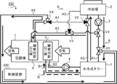
- the air conditioning system 101 is a system that air-conditions a space to be air-conditioned (hereinafter referred to as “air-conditioned space”) using the cooling water cooled by the cooling tower 2.
- Air conditioning refers to adjusting the temperature, humidity, cleanliness, airflow, or the like of air in an air-conditioned space, and specifically includes heating, cooling, dehumidification, humidification, air purification, and the like.
- the air-conditioned space is an internal space such as a general house, apartment house, office building, facility, or factory.
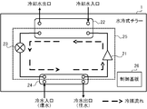
- an air conditioning system 101 includes a water-cooled chiller 1 that generates cold water, a cooling tower 2 that cools cooling water with outside air, a cooling water pump 3 that circulates cooling water, and cold water that circulates cooling water.
- the pump 4 the first heat exchanger 5 that exchanges heat between air and cold water, the second heat exchanger 6 that exchanges heat between air and cooling water, and the first heat exchanger 5
- the air conditioner 7 including the second heat exchanger 6, the three valves (first valve V1, second valve V2, and third valve V3) for switching the flow path of the cooling water, and the entire system are controlled.
- a control device 200 a control device 200.
- the air conditioning system 101 circulates the cooling water as a cooling water or cooling water flow path between the components, the cooling water circulation path A for circulating the cooling water, the cooling water branch path A ′ branched from the cooling water circulation path A, and the cooling water.
- the air-conditioning system 101 is a so-called secondary refrigerant circulation type or indirect cooling system that uses cooling water as a primary refrigerant and cold water as a secondary refrigerant.
- the water-cooled chiller 1 is a device that generates cold water.
- Cold water is a medium for cooling air in an air-conditioned space.
- the water-cooled chiller 1 functions as a heat source device that exchanges heat between the cooling water and the cold water and cools the cold water using the cooling water as a cold heat source.
- the water-cooled chiller 1 is a heat pump chiller using, for example, CO 2 (carbon dioxide) or HFC (hydrofluorocarbon) as a refrigerant.
- the water-cooled chiller 1 is installed outside the air-conditioned space, for example, in the same site as the air-conditioned space.
- the water-cooled chiller 1 includes a compressor 21, a first refrigerant-water heat exchanger 22, an expansion device 23, a second refrigerant-water heat exchanger 24, and an annular structure. And a refrigerant circuit 25 connected to the control board 26.
- the refrigerant circuit 25 is a circuit in which the refrigerant circulates, and is also called a heat pump or a refrigeration cycle.
- the compressor 21 compresses the refrigerant flowing through the refrigerant circuit 25 and increases the temperature and pressure of the refrigerant.
- the compressor 21 includes an inverter circuit that can change the capacity (the amount of delivery per unit) according to the operating frequency (the number of revolutions).
- the compressor 21 changes the operating frequency according to the control value instructed from the control board 26.
- the refrigerant sucked into the compressor 21 is compressed and discharged into a high-temperature and high-pressure gas refrigerant.
- the first refrigerant-water heat exchanger 22 exchanges heat between the refrigerant flowing through the refrigerant circuit 25 and the cooling water supplied from the cooling tower 2.
- the first refrigerant-water heat exchanger 22 is a plate-type or double-tube type heat exchanger, for example.
- the high-temperature and high-pressure refrigerant compressed by the compressor 21 is condensed by exchanging heat with the cooling water in the first refrigerant-water heat exchanger 22 and changed into a high-pressure liquid.
- the refrigerant condenses in the first refrigerant-water heat exchanger 22 the temperature of the cooling water rises because the cooling water is given heat.
- the expansion device 23 expands the refrigerant flowing through the refrigerant circuit 25 and lowers the temperature and pressure of the refrigerant.
- the expansion device 23 changes the opening degree of the valve according to the control value instructed from the control board 26 and adjusts the amount of decompression of the refrigerant.
- the refrigerant changed to a high-pressure liquid in the first refrigerant-water heat exchanger 22 is decompressed to a low-temperature and low-pressure two-phase refrigerant by the expansion device 23.
- the second refrigerant-water heat exchanger 24 exchanges heat between the refrigerant flowing through the refrigerant circuit 25 and the cold water supplied from the air conditioner 7.
- the second refrigerant-water heat exchanger 24 is a heat exchanger such as a plate type or a double pipe type.
- the refrigerant decompressed by the expansion device 23 evaporates by exchanging heat with cold water in the second refrigerant-water heat exchanger 24, and changes to a low-pressure gas.
- the refrigerant that has changed to a low-pressure gas returns to the compressor 21 and is compressed again into a high-temperature and high-pressure gas.
- the refrigerant evaporates in the second refrigerant-water heat exchanger 24, the temperature of the cold water decreases because heat is taken away.
- the control board 26 includes a CPU, a ROM, a RAM, a communication interface, a readable / writable non-volatile semiconductor memory, and the like, although not shown.
- the control board 26 is communicably connected to the compressor 21 and the expansion device 23 via a communication line (not shown).
- the control board 26 is communicably connected to the control device 200 via a communication line (not shown).
- the control board 26 controls the operations of the compressor 21 and the expansion device 23 in accordance with the instruction transmitted from the control device 200.
- the cooling tower 2 is equipment for cooling the cooling water.
- the cooling water is a medium for cooling the cold water with the water-cooled chiller 1.
- the cooling tower 2 includes a blower that blows outside air, and cools the cooling water by exchanging heat between the cooling water and the outside air. More specifically, the cooling tower 2 is a method in which the cooling water is directly contacted with the outside air to evaporate (open type), or the heat medium that is in contact with the outside air is circulated to indirectly cool the cooling water with the outside air.
- the cooling water is cooled by a method of contacting and evaporating (sealed type). As described above, the cooling tower 2 cools the cooling water by bringing the outside air into direct or indirect contact with the cooling water.
- the cooling tower 2 is installed outside the air-conditioned space, for example, in the same site as the air-conditioned space.
- the cooling tower 2 includes a control board including a CPU, a ROM, a RAM, a communication interface, a readable / writable non-volatile semiconductor memory, and the like, although not shown.
- the control board is communicably connected to the control device 200 via a communication line (not shown). The control board controls the operation of the cooling tower 2 according to the instruction transmitted from the control device 200.
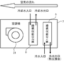
- the air conditioner 7 is a facility that air-conditions the air-conditioned space.
- the air conditioner 7 is also referred to as AHU (air handling unit).
- the air conditioner 7 is installed in a place where air conditioned in the conditioned space can be supplied.
- the air conditioner 7 is installed, for example, on the upper part of the wall of the air-conditioned space or on the ceiling.
- the air conditioner 7 may be installed in a dedicated machine room connected by a duct to a plurality of rooms, each of which is an air-conditioned space.
- the air conditioner 7 includes a first heat exchanger 5 that exchanges heat between air and cold water, and a second heat exchanger 6 that exchanges heat between air and cooling water. And an air blowing device 31 for blowing air.
- Both the first heat exchanger 5 and the second heat exchanger 6 are well-known heat exchangers that exchange heat between air and water.
- the first heat exchanger 5 exchanges heat between the cold water generated by the water-cooled chiller 1 and air.
- the second heat exchanger 6 is installed on the downstream side of the first heat exchanger 5, and a part of the cooling water cooled by the cooling tower 2 and the first heat exchanger 5 chilled water and heat Exchange heat with the exchanged air.
- the air sucked into the air conditioner 7 by the air blower 31 first passes through the first heat exchanger 5 and exchanges heat with cold water.
- the air heat-exchanged with the cold water in the first heat exchanger 5 further passes through the second heat exchanger 6 and exchanges heat with the cooling water.
- the air sucked into the air conditioner 7 is supplied to the conditioned space after heat exchange is performed twice.
- the air conditioner 7 includes a control board including a CPU, a ROM, a RAM, a communication interface, a readable / writable nonvolatile semiconductor memory, and the like, although not shown.
- the control board is communicably connected to the control device 200 via a communication line (not shown).
- the control board controls the operation of the air conditioner 7 according to the instruction transmitted from the control device 200.
- the cooling water circulation path A is provided between the cooling tower 2 and the water-cooled chiller 1, and circulates the cooling water between the cooling tower 2 and the water-cooled chiller 1.
- the cooling water circulation path A includes a first cooling water path A1 and a second cooling water path A2 connected to the cooling tower 2 and the water cooling chiller 1, respectively.
- the first cooling water channel A1 is a cooling water supply channel (outward channel) that guides the cooling water cooled by the cooling tower 2 to the water-cooled chiller 1.
- the second cooling water channel A ⁇ b> 2 is a cooling water reflux channel (return channel) that guides the cooling water that has been cooled by the water-cooled chiller 1 to the cooling tower 2.
- the cooling water branch path A ′ is provided between the cooling water circulation path A and the second heat exchanger 6, and a part of the cooling water flowing through the cooling water circulation path A is branched to provide the second heat exchanger 6. It is a branch path to supply to.
- the cooling water branch A ′ guides a part of the cooling water led from the cooling tower 2 to the water-cooled chiller 1 in the cooling water circulation path A to the second heat exchanger 6. A part of the exchanged cooling water is guided to the cooling water circuit A.
- the cooling water branch A ′ includes a third cooling water passage A3 connected to the middle of the first cooling water passage A1 and the second heat exchanger 6, and a second heat exchange between the middle of the second cooling water passage A2. And a fourth cooling water channel A4 connected to the vessel 6.
- the third cooling water channel A3 guides a part of the cooling water flowing through the first cooling water channel A1 to the second heat exchanger 6.
- the fourth cooling water channel A4 guides the cooling water heat-exchanged with the air by the second heat exchanger 6 to the second cooling water channel A2.
- the cooling water branch A ′ includes a fifth cooling water channel A5 connected to the middle of the third cooling water channel A3 and the cooling tower 2.
- the fifth cooling water channel A5 is a bypass channel that guides the cooling water flowing through the third cooling water channel A3 to the cooling tower 2 without passing through the cooling water circuit A.
- the cooling water circulation path A is provided with a cooling water pump 3.
- the cooling water pump 3 sends out the cooling water generated by the cooling tower 2 and circulates through the cooling water circulation path A and the cooling water branch path A ′.
- the cooling water pump 3 includes an inverter circuit, and changes the amount of cooling water to be sent out by adjusting the drive rotation speed according to the control value instructed from the control device 200.
- the cooling water sent out from the cooling tower 2 by the cooling water pump 3 returns to the water cooling chiller 1 through one or both of the water cooling chiller 1 and the first heat exchanger 5.
- the cooling water circulation path A is provided with a first valve V1, a second valve V2, and a third valve V3.
- Each of the first valve V1, the second valve V2, and the third valve V3 is an electric three-way valve that opens and closes the valve by a known method such as an electromagnetic type or an electric type.
- Each of the first valve V1, the second valve V2, and the third valve V3 changes the flow path of the cooling water by switching the opening and closing of the valves in accordance with a control command from the control device 200.
- the first valve V1 allows the cooling water output from the cooling tower 2 to the first cooling water channel A1 to flow to the water-cooled chiller 1, the second heat exchanger 6, or the water-cooled chiller 1. And whether to flow to both the second heat exchanger 6.
- the second valve V2 includes the cooling water output from the water-cooled chiller 1 to the second cooling water passage A2, and the cooling water output from the second heat exchanger 6 to the fourth cooling water passage A4. Only one of the above is switched to the cooling tower 2 or both are switched to the cooling tower 2.
- the third valve V3 switches whether or not to guide the cooling water flowing through the third cooling water channel A3 to the fifth cooling water channel A5.
- the cold water circulation path B is provided between the water-cooled chiller 1 and the first heat exchanger 5 and circulates cold water between the water-cooled chiller 1 and the first heat exchanger 5.
- the cold water circulation path B includes a first cold water path B1 and a second cold water path B2 connected to the water-cooled chiller 1 and the first heat exchanger 5, respectively.
- the first cold water passage B ⁇ b> 1 is a cold water supply passage (outward water passage) that guides the cold water generated by the water-cooled chiller 1 to the first heat exchanger 5.
- the second cold water passage B2 is a cold water recirculation passage (return water passage) that guides the cold water heat-exchanged with the air by the first heat exchanger 5 to the water-cooled chiller 1.
- a cold water pump 4 is provided in the cold water circulation path B.
- the cold water pump 4 sends out the cold water generated by the water-cooled chiller 1 and circulates the cold water circulation path B.
- the chilled water pump 4 includes an inverter circuit, and changes the amount of chilled water to be sent out by adjusting the drive rotation speed according to the control value instructed from the control device 200.
- the cold water sent out from the water-cooled chiller 1 by the cold water pump 4 returns to the water-cooled chiller 1 through the first heat exchanger 5.
- Control device 200 controls the entire air conditioning system 101 in an integrated manner.
- the control device 200 is installed, for example, inside the air-conditioned space or at an appropriate place in the same site as the air-conditioned space.
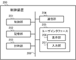
- FIG. 4 shows the hardware configuration of the control device 200.
- the control device 200 includes a control unit 201, a storage unit 202, a time measuring unit 203, a communication unit 204, and a user interface 205. These units are connected via a bus 209.
- the control unit 201 includes a CPU, a ROM, a RAM, and the like, although not shown.
- the CPU is also called a central processing unit, a central processing unit, a processor, a microprocessor, a microcomputer, a DSP (Digital Signal Processor), or the like.
- the CPU reads a program and data stored in the ROM, and performs overall control of the control device 200 using the RAM as a work area.
- the storage unit 202 is a non-volatile semiconductor memory such as a flash memory, an EPROM (Erasable Programmable ROM), or an EEPROM (Electrically Erasable Programmable ROM), and serves as a so-called secondary storage device (auxiliary storage device). .
- the storage unit 202 stores various programs and data used by the control unit 201 to perform various processes, and various data generated or acquired by the control unit 201 performing various processes.
- the timekeeping unit 203 includes an RTC (Real Time Clock), and is a time measuring device that keeps time while the power of the control device 200 is off.
- RTC Real Time Clock
- the communication unit 204 is an interface for communicating with an external device.
- the communication unit 204 is connected to each of the water-cooled chiller 1, the cooling tower 2, the cooling water pump 3, the cold water pump 4, the air conditioner 7, the first valve V1, the second valve V2, and the third valve V3, wired or It is connected so as to be communicable wirelessly, and communicates with these components in accordance with a known communication standard.
- the communication unit 204 is connected to a local area network and a wide area network, and communicates with devices outside the air conditioning system 101.
- the user interface 205 includes a display unit 206 and an input unit 207.
- the display unit 206 is a display device such as an LCD (Liquid Crystal Display) panel, an organic EL, or an LED (Light Emitting Diode).
- the input unit 207 is an input device such as a touch panel, a touch pad, a switch, or various press buttons.
- the user interface 205 accepts various operations from the user via the input unit 207 and displays various display images via the display unit 206.
- the display unit 206 and the input unit 207 may be configured as a touch panel (touch screen) in which these are superimposed on each other.
- the control apparatus 200 may include a user interface 205 (display unit 206 and input unit 207) in the apparatus main body.
- the user interface 205 is not included in the apparatus main body, and a remote controller separated from the apparatus main body is used as the user interface 205. It may be functioning.
- the control device 200 communicates with the remote control via the communication unit 204.
- the communication unit 204 transmits a signal indicating a display image on the display unit 206 of the remote control, and receives a signal indicating the operation content received from the user by the input unit 207 of the remote control.
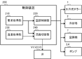
- the control unit 201 functionally includes a request acquisition unit 210, an air conditioning control unit 220, a temperature acquisition unit 230, and a flow path switching unit 240.
- Each of these functions is realized by software, firmware, or a combination of software and firmware.
- Software and firmware are described as programs and stored in the ROM or the storage unit 202.
- Each function is realized by the CPU executing a program stored in the ROM or the storage unit 202.
- the request acquisition unit 210 acquires an operation request for the air conditioning system 101.
- the user can input a request such as start of air conditioning, end of air conditioning, change of set temperature, or change of operation mode by operating the input unit 207 or from the outside via the communication unit 204. .
- the request acquisition unit 210 acquires the request input from the user in this way.
- the request acquisition unit 210 acquires an operation request issued according to a predetermined operation schedule via the communication unit 204.
- the request acquisition unit 210 is realized by the control unit 201 cooperating with the communication unit 204 or the input unit 207.
- the air conditioning system 101 can be air-conditioned in the “cooling” or “reheat dehumidification” operation mode, as will be described in detail later. More specifically, there are “normal cooling” and “free cooling” as operation modes of “cooling”, and “first reheat dehumidification” and “second reheat” as operation modes of “reheat dehumidification”. There is “heat dehumidification”. The user can select a desired operation mode from among the operation modes of “cooling” or “reheat dehumidification”. The request acquisition unit 210 acquires the operation mode selected in this way.
- the air conditioning control unit 220 controls the air conditioning operation in the air conditioning system 101. Specifically, the air conditioning control unit 220 communicates with each of the water-cooled chiller 1, the cooling tower 2, the cooling water pump 3, the cold water pump 4, and the air conditioner 7 via the communication unit 204, and operates each device. Send instructions.
- the air conditioning control unit 220 is realized by the control unit 201 cooperating with the communication unit 204.
- the air conditioning control unit 220 transmits an operation start instruction for the water-cooled chiller 1 to the control board 26 to drive the compressor 21 and the expansion device 23.
- the water-cooled chiller 1 generates cold water.
- the air conditioning control unit 220 drives the cooling water pump 3 and the cold water pump 4 to circulate the cooling water and the cold water.
- the air conditioning control unit 220 transmits an operation start instruction to the cooling tower 2 and the air conditioner 7, causes the cooling tower 2 to cool the cooling water, and causes the air conditioner 7 to start air conditioning.
- the temperature acquisition unit 230 acquires the outside air temperature.
- the outside air temperature is outside the air-conditioned space and means the temperature of outdoor air.
- the outside air temperature is detected by a temperature sensor such as a thermistor or a thermocouple provided outdoors.
- the temperature acquisition unit 230 acquires information on the outside air temperature detected by the temperature sensor via the communication unit 204.
- the temperature acquisition unit 230 is realized when the control unit 201 cooperates with the communication unit 204.
- the flow path switching unit 240 switches the flow path of the cooling water in the cooling water circulation path A and the cooling water branch path A ′.
- the cooling water flow path is a path through which the cooling water circulates in the cooling water circulation path A and the cooling water branch path A ′.
- the flow path switching unit 240 transmits an instruction to switch opening / closing of the valve to each of the first valve V1, the second valve V2, and the third valve V3 via the communication unit 204, thereby cooling the three-way valve. Switch the direction of water flow. Thereby, the flow path switching unit 240 changes the flow path of the cooling water.
- the flow path switching unit 240 is realized by the control unit 201 cooperating with the communication unit 204.
- the flow path switching unit 240 switches the cooling water flow path according to the operation mode acquired by the request acquisition unit 210 and the outside air temperature acquired by the temperature acquisition unit 230.
- the air conditioning system 101 operates in each operation mode of “normal cooling”, “first reheat dehumidification”, “second reheat dehumidification”, and “free cooling” will be described.
- the normal cooling is an operation mode in which the air-conditioned space is cooled by cooling air with the cold water generated by the water-cooled chiller 1.
- the flow path switching unit 240 switches the flow path of the cooling water to a flow path in which all the cooling water flowing through the first cooling water path A1 is supplied to the water-cooled chiller 1.
- the first condition is a condition in which the air conditioning system 101 starts air conditioning in the “normal cooling” operation mode. More specifically, the first condition is satisfied when the request acquisition unit 210 acquires a cooling start request or when the timing for starting the cooling determined in the operation schedule arrives.
- FIG. 6 shows the flow path of the cooling water during normal cooling.
- the flow path switching unit 240 transmits an instruction to the first valve V1 and the second valve V2, and switches the valve on the third cooling water channel A3 side in the first valve V1. Close the valve on the fourth cooling water channel A4 side in the second valve V2. By closing the valve on the third cooling water passage A3 side in the first valve V1, the cooling water cooled in the cooling tower 2 is not supplied to the cooling water branch A ′ and the second heat exchanger 6, All of this is supplied to the water-cooled chiller 1.
- the cooling water after cooling the cold water with the water-cooled chiller 1 is the cooling water branch A ′ and the second heat exchanger 6. Are all supplied to the cooling tower 2. In this way, the cooling water circulates between the cooling tower 2 and the water-cooled chiller 1. In such a flow path, the temperature of the cooling water decreases by absorbing heat to the outside air in the cooling tower 2 and increases by cooling the cold water in the water-cooled chiller 1.
- the cold water cooled by the cooling water in the water-cooled chiller 1 is circulated between the water-cooled chiller 1 and the first heat exchanger 5 by the cold water pump 4. At this time, the temperature of the cold water decreases by exchanging heat with the cooling water in the water-cooled chiller 1 and increases by exchanging heat with the air in the first heat exchanger 5.
- the first heat exchanger 5 exchanges heat between cold water and air, thereby reducing the temperature and humidity of the air and supplying low-temperature and low-humidity air to the air-conditioned space. Thereby, the air-conditioned space is cooled.
- the second heat exchanger 6 is not used because the cooling water does not flow through the cooling water branch A ′.
- the air conditioning system 101 cools the air-conditioned space by heat exchange in the first heat exchanger 5.
- FIG. 6 the direction in which the three-way valve is closed is shown in black. Further, in the cooling water circulation path A and the cooling water branching path A ′, the flow paths through which the cooling water flows are indicated by solid lines, and the flow paths through which the cooling water does not flow are indicated by dotted lines. The same applies to the subsequent drawings.
- first reheat dehumidification is an operation mode in which air is cooled with cold water to reduce the humidity, and then air is reheated with cooling water and supplied to the air-conditioned space.
- the air conditioning system 101 can be operated in two operation modes of “first reheat dehumidification” and “second reheat dehumidification” as reheat dehumidification.
- the “first reheat dehumidification” is an operation mode that is executed in summer when the outside air temperature and the cooling water temperature are relatively high
- the “second reheat dehumidification” is the outside air temperature and the cooling water temperature. This is an operation mode executed in a relatively low intermediate period or winter period.
- the flow path switching unit 240 is configured such that a part of the cooling water flowing through the first cooling water path A1 passes through the third cooling water path A3 through the second cooling water path A3. A part other than the part (that is, the remaining part) of the cooling water supplied to the heat exchanger 6 and flowing through the first cooling water path A1 is switched to a flow path supplied to the water-cooled chiller 1.
- the second condition is a condition in which the air conditioning system 101 starts air conditioning in the operation mode of “first reheat dehumidification”. Specifically, the second condition is established when reheat dehumidification is requested and when the outside air temperature acquired by the temperature acquisition unit 230 is larger than the first threshold.
- the case where reheat dehumidification is requested is when the request acquisition unit 210 acquires a request for starting reheat dehumidification, or when the timing for starting reheat dehumidification defined in the operation schedule has arrived.
- the first threshold value is a reference temperature for switching between “first reheat dehumidification” and “second reheat dehumidification”, and is set in advance to, for example, 25 ° C. or 30 ° C.
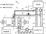
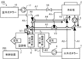
- FIG. 7 shows the flow path of the cooling water during the first reheat dehumidification.
- the flow path switching unit 240 sends instructions to each of the three valves V1 to V3 to open all the valves in the first valve V1 and the second valve V2, And the valve by the side of the 5th cooling water channel A5 in the 3rd valve V3 is closed.
- the cooling water cooled in the cooling tower 2 is divided and supplied to both the water-cooled chiller 1 and the second heat exchanger 6.
- the first part of the cooling water cooled by the cooling tower 2 is supplied to the water-cooled chiller 1, and the second part other than the first part is supplied to the second heat exchanger 6.
- the first valve after the chilled water is cooled by the water-cooled chiller 1 by opening all the valves in the second valve V2 and closing the valve on the fifth cooling water channel A5 side in the third valve V3.
- the cooling water in the part and the cooling water in the second part after heat exchange with the air in the second heat exchanger 6 are merged in the second valve V2, mixed, and returned to the water-cooled chiller 1. In this way, the cooling water circulates between the cooling tower 2 and the water-cooled chiller 1 and between the cooling tower 2 and the second heat exchanger 6.
- the temperature of the cooling water decreases by absorbing heat to the outside air in the cooling tower 2, increases by cooling the cold water in the water-cooled chiller 1, and air in the second heat exchanger 6.
- the temperature decreases by reheating the.
- the cooling water of the first part whose temperature has been increased by the water-cooled chiller 1 is cooled by mixing the cooling water of the second part whose temperature has been decreased by the second heat exchanger 6 with the second valve V2.
- the temperature drops to some extent. Therefore, the load for cooling the cooling water in the cooling tower 2 is reduced, and energy consumption can be saved.
- the cold water cooled by the cooling water in the water-cooled chiller 1 is circulated between the water-cooled chiller 1 and the first heat exchanger 5 by the cold water pump 4. At this time, the temperature of the cold water decreases by exchanging heat with the cooling water in the water-cooled chiller 1 and increases by exchanging heat with the air in the first heat exchanger 5.
- the first heat exchanger 5 reduces the temperature and humidity of the air by exchanging heat between the cold water generated by the water-cooled chiller 1 and the air. By being cooled to cold water by the first heat exchanger 5, the temperature of the air is lower than the temperature of the cooling water supplied from the cooling tower 2.
- the second heat exchanger 6 exchanges heat between a part of the cooling water supplied from the cooling tower 2 and the air heat-exchanged with the cold water in the first heat exchanger 5, so that the air Reheat.
- FIG. 8 shows a change in air temperature and humidity when passing through the first heat exchanger 5 and the second heat exchanger 6 on an air diagram.
- both the temperature and humidity of the air are relatively high near the inlet of the first heat exchanger 5, that is, before the air flows into the air conditioner 7.
- the temperature and humidity of the air near the outlet of the first heat exchanger 5 are reduced by being cooled to cold water by the first heat exchanger 5.
- the temperature of the air near the exit of the second heat exchanger 6 increases by being reheated to the cooling water by the second heat exchanger 6.
- the medium-temperature and low-humidity air generated in this way is supplied to the conditioned space.
- the air conditioning system 101 regenerates the conditioned space by the two-stage heat exchange between the first heat exchanger 5 and the second heat exchanger 6. Heat dehumidify.
- the flow path switching unit 240 supplies all of the cooling water flowing through the first cooling water path A1 to the water-cooled chiller 1 through the cooling water flow path.
- the cooling water cooled is supplied to the second heat exchanger 6 via the second cooling water channel A2 and the fourth cooling water channel A4, and exchanged heat with air in the second heat exchanger 6.
- the cooling water is switched to a flow path that is supplied to the cooling tower 2 via the third cooling water path A3 and the fifth cooling water path A5.
- the third condition is a condition in which the air conditioning system 101 starts air conditioning in the operation mode of “second reheat dehumidification”. Specifically, the third condition is established when reheat dehumidification is requested and when the outside air temperature acquired by the temperature acquisition unit 230 is smaller than the first threshold.
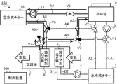
- FIG. 9 shows the flow path of the cooling water during the second reheat dehumidification.
- the flow path switching unit 240 transmits an instruction to each of the three valves V1 to V3 to close the valve on the third cooling water channel A3 side in the first valve V1,
- the valve on the cooling tower 2 side in the second valve V2 is closed, and the valve on the first valve V1 side in the third valve V3 is closed.
- the cooling water cooled in the cooling tower 2 is not supplied to the cooling water branch A ′ and the second heat exchanger 6, All of this is supplied to the water-cooled chiller 1.
- the cooling water after cooling the cooling water with the water-cooled chiller 1 is not supplied to the cooling tower 2, and all of the cooling water is the fourth cooling. It is supplied to the second heat exchanger 6 via the water channel A4. Further, by closing the valve on the first valve V1 side in the third valve V3, the cooling water after the heat exchange with the air in the second heat exchanger 6 is performed in the third cooling water channel A3 and the fifth cooling water channel A3. It returns to the cooling tower 2 via the cooling water channel A5. Thus, the cooling water circulates in the order of the cooling tower 2, the water-cooled chiller 1, and the second heat exchanger 6.
- the temperature of the cooling water decreases by absorbing heat to the outside air in the cooling tower 2, increases by cooling the cold water in the water-cooled chiller 1, and air in the second heat exchanger 6.
- the temperature decreases by reheating the.
- the temperature of the cooling water whose temperature has increased in the water-cooled chiller 1 decreases to some extent before returning to the cooling tower 2 due to reheating of the air in the second heat exchanger 6. Therefore, the load for cooling the cooling water in the cooling tower 2 is reduced, and energy consumption can be saved.
- the cold water cooled by the cooling water in the water-cooled chiller 1 is circulated between the water-cooled chiller 1 and the first heat exchanger 5 by the cold water pump 4. At this time, the temperature of the cold water decreases by exchanging heat with the cooling water in the water-cooled chiller 1 and increases by exchanging heat with the air in the first heat exchanger 5.
- the first heat exchanger 5 reduces the temperature and humidity of the air by exchanging heat between the cold water generated by the water-cooled chiller 1 and the air. By cooling to cold water with the 1st heat exchanger 5, the temperature of air falls rather than the temperature of the cooling water after cooling cold water with the water cooling type chiller 1.
- FIG. The second heat exchanger 6 exchanges heat between the cooling water after cooling the cold water with the water-cooled chiller 1 and the air heat-exchanged with the cold water with the first heat exchanger 5, Reheat the air. Changes in the temperature and humidity of the air at this time are the same as in FIG.
- the air conditioning system 101 regenerates the conditioned space by the two-stage heat exchange between the first heat exchanger 5 and the second heat exchanger 6.
- Heat dehumidify In “first reheat dehumidification”, the cooling water is supplied directly from the cooling tower 2 to the second heat exchanger 6, whereas in “second reheat dehumidification”, the cooling water is a water-cooled chiller. After being heated by the exhaust heat at 1, it is supplied to the second heat exchanger 6. Therefore, “second reheat dehumidification” is an effective operation mode when the temperature of the cooling water is relatively lower than “first reheat dehumidification”.
- the air conditioning system 101 When reheat dehumidification is requested, the air conditioning system 101 operates by changing the operation mode of “first reheat dehumidification” and the operation mode of “second reheat dehumidification” according to the outside air temperature. .
- the flow path switching unit 240 switches the flow path of the cooling water according to such a change in the operation mode.
- Free cooling is an operation mode in which cooling is performed with cooling water cooled by the cooling tower 2 without using the water-cooled chiller 1 when the temperature of the cooling water is sufficiently low in the winter or intermediate period.
- the flow path switching unit 240 is configured so that the cooling water flowing through the first cooling water path A1 is not supplied to the water-cooled chiller 1 and the first cooling water path A1 is passed through the cooling water flow path. All the flowing cooling water is switched to a flow path that is supplied to the second heat exchanger 6 via the third cooling water path A3.
- the fourth condition is a condition in which the air conditioning system 101 starts air conditioning in the “free cooling” operation mode. Specifically, the fourth condition is established when cooling is requested and the outside air temperature acquired by the temperature acquisition unit 230 is smaller than the second threshold.
- the case where cooling is requested is when the request acquisition unit 210 acquires a request for starting cooling, or when the timing for starting the cooling determined in the operation schedule has arrived.
- the second threshold is a reference temperature for switching the operation mode from “normal cooling” to “free cooling”, and is set in advance to 5 ° C. or 10 ° C., for example.
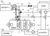
- Fig. 10 shows the flow path of the cooling water during free cooling.
- the flow path switching unit 240 transmits an instruction to each of the three valves V1 to V3, so that the water cooling chiller 1 side of the first valve V1 and the second valve V2 is on the side.
- the valve is closed, and the valve on the fifth cooling water channel A5 side in the third valve V3 is closed.
- the cooling water cooled by the cooling tower 2 is not supplied to the water-cooled chiller 1, all of which passes through the third cooling water channel A3. Then, it is supplied to the second heat exchanger 6.
- the cooling water after heat exchange with air in the second heat exchanger 6 is not supplied to the water-cooled chiller 1, All of this is supplied to the cooling tower 2.
- the cooling water circulates between the cooling tower 2 and the second heat exchanger 6. In such a flow path, the temperature of the cooling water decreases by absorbing heat to the outside air in the cooling tower 2 and increases by cooling the air in the second heat exchanger 6.
- the second heat exchanger 6 reduces the temperature and humidity of the air by exchanging heat between the cooling water and the air, and supplies low-temperature and low-humidity air to the air-conditioned space. Thereby, the air-conditioned space is cooled. During free cooling, the water-cooled chiller 1, the cold water pump 4, and the first heat exchanger 5 are stopped.
- the air conditioning system 101 supplies the cooling water cooled by the outside air in the cooling tower 2 to the second heat exchanger 6 as it is to cool the conditioned space. Since the water-cooled chiller 1, the cold water pump 4 and the first heat exchanger 5 are not used, energy consumption can be saved.
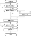
- the flow of air conditioning processing executed in the control device 200 of the air conditioning system 101 configured as described above will be described with reference to the flowchart shown in FIG.
- the air conditioning process illustrated in FIG. 11 is executed as needed by the control unit 201 in a state where power is supplied to the air conditioning system 101 and the air conditioning system 101 can be air conditioned.
- the control unit 201 first determines whether or not a request for starting air conditioning has been acquired (step S1). More specifically, the control unit 201 determines whether or not an input of an air conditioning start request has been received from the user via the input unit 207 or the communication unit 204. Further, the control unit 201 determines that the request for starting air conditioning has been acquired also when the timing for starting air conditioning predetermined in the operation schedule has arrived. In step S ⁇ b> 1, the control unit 201 functions as the request acquisition unit 210.
- step S1 When the request for starting air conditioning has not been acquired (step S1; NO), the control unit 201 stops the process at step S1 and waits until the request for starting air conditioning is acquired.
- step S2 determines whether the operation mode of the air conditioning system 101 should be changed (step S2). For example, the control unit 201 determines that the operation mode should be changed when a request for changing the operation mode is acquired from the user or when the outside air temperature satisfies a condition for switching the operation mode.
- step S ⁇ b> 2 the control unit 201 functions as the request acquisition unit 210 and the temperature acquisition unit 230.
- step S3 When changing the operation mode (step S2; YES), the control unit 201 changes the flow path of the cooling water (step S3). If demonstrating it concretely, the control part 201 will transmit the instruction
- step S2 when the operation mode is not changed (step S2; NO), the control unit 201 skips the process of step S3.
- step S4 the control unit 201 starts air conditioning (step S4). More specifically, the control unit 201 transmits an operation start instruction to the water-cooled chiller 1, the cooling tower 2, the cooling water pump 3, the cold water pump 4, and the air conditioner 7 via the communication unit 204. In step S ⁇ b> 4, the control unit 201 functions as the air conditioning control unit 220.
- control unit 201 determines whether or not a request for air conditioning termination has been acquired (step S5). More specifically, the control unit 201 determines whether or not an input of an air conditioning end request has been received from the user via the input unit 207 or the communication unit 204. Further, the control unit 201 determines that the request for air conditioning termination has been acquired also when the timing for terminating air conditioning predetermined in the operation schedule has come. In step S ⁇ b> 5, the control unit 201 functions as the request acquisition unit 210.
- step S5 When the request for air conditioning end has not been acquired (step S5; NO), the control unit 201 stops the process at step S5 and continues air conditioning until the request for air conditioning end is acquired.
- step S6 when the air conditioning end request is acquired (step S5; YES), the control unit 201 ends the air conditioning (step S6). More specifically, the control unit 201 transmits an operation end instruction to the water-cooled chiller 1, the cooling tower 2, the cooling water pump 3, the cold water pump 4, and the air conditioner 7 via the communication unit 204. In step S ⁇ b> 6, the control unit 201 functions as the air conditioning control unit 220. Thus, the air conditioning process shown in FIG. 11 ends.
- the air conditioning system 101 includes the cooling tower A ′ that is branched from the cooling water circulation path A ′ that circulates the cooling water between the cooling tower 2 and the water-cooled chiller 1.
- a part of the cooling water led from 2 to the water-cooled chiller 1 is supplied to the second heat exchanger 6. Since the air is reheated using the heat of the cooling water without requiring a dedicated heat source device for reheating, energy consumption is saved and costs are reduced.
- the cooling water can be used effectively even when the outside air temperature at which free cooling cannot be performed is relatively high. Since the cooling water branch path A ′ for branching the cooling water to the air conditioner 7 can be used not only for free cooling but also for reheat dehumidification, cost effectiveness for the addition of equipment can be enhanced.
- the air conditioning system 101 can switch the operation modes of normal cooling, first reheat dehumidification, second reheat dehumidification, and free cooling depending on the situation. As a result, it is possible to effectively use the cooling water in various situations for air conditioning, and to improve user convenience.
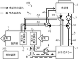
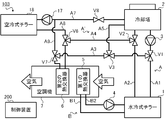
- FIG. 12 shows an outline of the air conditioning system 102 according to the second embodiment.
- the air conditioning system 102 includes a water-cooled chiller 1, a cooling tower 2, a cooling water pump 3, a cold water pump 4, a first heat exchanger 5, a second heat exchanger 6, an air conditioner 7, A cooling water circulation path A, a cooling water branch path A ′, a cooling water circulation path B, a first valve V 1, a second valve V 2, a third valve V 3, and a control device 200 are provided. Since each of these configurations is the same as that of the first embodiment, description thereof is omitted.
- the air conditioning system 102 includes a sixth cooling water channel A6 that guides a part of the cooling water heat-exchanged with air by the second heat exchanger 6 to the first cooling water channel A1, and the cooling water. And a fourth valve V4 and a fifth valve V5 for switching the flow paths.
- the sixth cooling water channel A6 is a position between the branch position of the first cooling water channel A1 to the third cooling water channel A3 (that is, the position where the first valve V1 is provided) and the water-cooled chiller 1. It is connected to the middle of the fourth cooling water channel A4.
- a fourth valve V4 is provided at a branch position of the fourth cooling water path A4 to the sixth cooling water path A6, and a branch position of the first cooling water path A1 to the sixth cooling water path A6 is provided at the branch position.
- a fifth valve V5 is provided.
- Each of the fourth valve V4 and the fifth valve V5 is a three-way valve that opens and closes the valve by a known method such as an electromagnetic type or an electric type.
- the fourth valve V4 switches whether or not to supply the cooling water flowing through the fourth cooling water channel A4 to the sixth cooling water channel A6 by opening and closing the valve according to the control command from the flow path switching unit 240.
- the fifth valve V5 switches whether or not to supply the cooling water flowing through the sixth cooling water channel A6 to the first cooling water channel A1 by opening and closing the valve according to the control command from the flow path switching unit 240.
- the air conditioning system 102 can perform air conditioning in four operation modes of “normal cooling”, “first reheat dehumidification”, “second reheat dehumidification”, and “free cooling”.
- the flow path switching unit 240 transmits an instruction to switch opening / closing of the valves to each of the five valves V1 to V5 via the communication unit 204 in accordance with the operation mode executed by the air conditioning system 102, thereby allowing the flow of the cooling water to flow. Switch the road.
- the three operation modes of “normal cooling”, “second reheat dehumidification”, and “free cooling” are the same as in the first embodiment.
- the flow path switching unit 240 closes the valve on the sixth cooling water channel A6 side in the fourth valve V4, and the sixth valve in the fifth valve V5.
- the valve on the cooling water channel A6 side is closed.
- the flow path of the cooling water is the same as in the first embodiment. Therefore, description of these three operation modes is omitted.
- the flow path switching unit 240 is configured such that a part of the cooling water flowing through the first cooling water path A1 passes through the third cooling water path A3 through the second cooling water path A3.
- a part (that is, the remaining part) other than a part of the cooling water that is supplied to the heat exchanger 6 and flows through the first cooling water passage A1 is supplied to the water-cooled chiller 1 and air is supplied to the second heat exchanger 6 by air.
- a part of the cooling water heat-exchanged with the first cooling water channel A6 and the first cooling water channel A1 is switched to the flow channel supplied to the water-cooled chiller 1.
- the second condition is a condition in which the air conditioning system 102 starts air conditioning in the operation mode of “first reheat dehumidification”. Specifically, the second condition is established when reheat dehumidification is requested and when the outside air temperature acquired by the temperature acquisition unit 230 is larger than the first threshold.
- FIG. 13 shows the flow path of the cooling water during the first reheat dehumidification.
- the flow path switching unit 240 sends instructions to each of the five valves V1 to V5 to open all the valves in the first valve V1 and the fifth valve V5,
- the valve on the fourth cooling water channel A4 side in the second valve V2 is closed
- the valve on the fifth cooling water channel A5 side in the third valve V3 is closed
- the second valve V2 side in the fourth valve V4 Close the valve.
- the cooling water cooled by the cooling tower 2 is divided and supplied to both the water-cooled chiller 1 and the second heat exchanger 6.
- the first part of the cooling water cooled by the cooling tower 2 is supplied to the water-cooled chiller 1, and the second part other than the first part is supplied to the second heat exchanger 6.
- the cooling water after cooling the cold water with the water-cooled chiller 1 is the cooling water branch A ′ and the second heat exchanger 6. Are all supplied to the cooling tower 2.
- the second heat exchanger 6 to the fourth valve
- the cooling water of the second part output to the cooling water channel A4 is supplied to the first cooling water channel A1 via the sixth cooling water channel A6.
- the cooling water in the second part that has flowed in from the sixth cooling water passage A6 in the fifth valve V5 and has exchanged heat with air in the second heat exchanger 6 is divided in the first valve V1. 1 is combined with the cooling water of part 1 and supplied to the water-cooled chiller 1.
- the temperature of the cooling water decreases by absorbing heat to the outside air in the cooling tower 2, increases by cooling the cold water in the water-cooled chiller 1, and air in the second heat exchanger 6. The temperature is further lowered by reheating. Therefore, the temperature of the cooling water flowing into the water-cooled chiller 1 from the second heat exchanger 6 via the sixth cooling water channel A6 is lower than the temperature of the cooling water cooled by the cooling tower 2. In other words, cooling water having a temperature lower than that of the cooling water cooled by the cooling tower 2 is supplied to the water-cooled chiller 1.
- the cold water cooled by the cooling water in the water-cooled chiller 1 is circulated between the water-cooled chiller 1 and the first heat exchanger 5 by the cold water pump 4. At this time, the temperature of the cold water decreases by exchanging heat with the cooling water in the water-cooled chiller 1 and increases by exchanging heat with the air in the first heat exchanger 5.
- the first heat exchanger 5 reduces the temperature and humidity of the air by exchanging heat between the cold water generated by the water-cooled chiller 1 and the air.
- the second heat exchanger 6 exchanges heat between the cooling water after cooling the cold water with the water-cooled chiller 1 and the air heat-exchanged with the cold water with the first heat exchanger 5. Changes in the temperature and humidity of the air at this time are the same as in FIG.
- the temperature of the cooling water flowing into the water-cooled chiller 1 can be lowered while achieving the effects in the first embodiment. Therefore, the cooling efficiency of the water-cooled chiller 1 is improved, and energy consumption can be saved. Thereby, even if the temperature of the cooling water is particularly high, the cold water can be efficiently cooled by the water-cooled chiller 1.
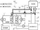
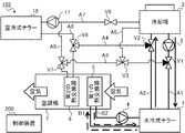
- FIG. 14 shows an outline of the air conditioning system 103 according to the third embodiment.
- the air conditioning system 103 includes a water-cooled chiller 1, a cooling tower 2, a cooling water pump 3, a cold water pump 4, a first heat exchanger 5, a second heat exchanger 6, an air conditioner 7, A cooling water circulation path A, a cooling water branch path A ′, a cooling water circulation path B, a first valve V 1, a second valve V 2, a third valve V 3, and a control device 200 are provided. Since each of these configurations is the same as that of the first embodiment, description thereof is omitted.
- the air conditioning system 103 includes a cooling water pump 17 that circulates cooling water, an air-cooled chiller 18 that cools or heats the cooling water, and a seventh cooling water channel that guides the cooling water to the air-cooled chiller 18.
- A7, the eighth cooling water channel A8 for guiding the cooling water cooled or heated by the air-cooled chiller 18 to the second heat exchanger 6, and the cooling water heat-exchanged with the air by the second heat exchanger 6 are air-cooled.
- a ninth cooling water passage A9 that leads to the chiller 18 and a sixth valve V6, a seventh valve V7, and an eighth valve V8 that switch the cooling water flow path are provided.
- the air-cooled chiller 18 is a device that cools or heats the cooling water by exchanging heat between the outside air and the cooling water.
- the air-cooled chiller 18 is a heat pump chiller using, for example, CO 2 (carbon dioxide) or HFC (hydrofluorocarbon) as a refrigerant.
- the air-cooled chiller 18 is installed, for example, outside the air-conditioned space and in the same site as the air-conditioned space.
- the water-cooled chiller 1 functions as a first heat source device that cools the cold water, whereas the air-cooled chiller 18 functions as a second heat source device that cools or heats the cooling water.
- the air-cooled chiller 18 includes a compressor that compresses the refrigerant, a four-way valve that switches the refrigerant flow path, a refrigerant-air heat exchanger that exchanges heat between the refrigerant and the outside air, and a refrigerant.
- the refrigerant circuit is a circuit through which the refrigerant circulates, and is also called a heat pump or a refrigeration cycle.
- the control board includes a CPU, a ROM, a RAM, a communication interface, a readable / writable nonvolatile semiconductor memory, and the like.
- the control board is communicably connected to the control device 200 via a communication line (not shown).
- the control board controls the operation of the air-cooled chiller 18 in accordance with the instruction transmitted from the control device 200.
- the control board switches the flow path of the four-way valve so that the refrigerant discharged from the compressor flows into the refrigerant-air heat exchanger, and drives the expansion device and the compressor.
- the compressor is driven, the refrigerant discharged from the compressor passes through the four-way valve, flows into the refrigerant-air heat exchanger, exchanges heat with the outside air, and condenses.
- the condensed refrigerant is depressurized by the expansion device, then flows into the refrigerant-water heat exchanger, exchanges heat with the cooling water, and evaporates.
- the evaporated refrigerant passes through the four-way valve and is sucked into the compressor again.
- the low-temperature refrigerant flows into the refrigerant-water heat exchanger, whereby the cooling water passing therethrough is cooled.
- the control board switches the flow path of the four-way valve so that the refrigerant discharged from the compressor flows into the refrigerant-water heat exchanger, and drives the expansion device and the compressor.
- the compressor When the compressor is driven, the refrigerant discharged from the compressor passes through the four-way valve, flows into the refrigerant-water heat exchanger, exchanges heat with the cooling water, and condenses.
- the condensed refrigerant is decompressed by the expansion device, then flows into the refrigerant-air heat exchanger, and evaporates by exchanging heat with the outside air.
- the evaporated refrigerant passes through the four-way valve and is sucked into the compressor again. In this way, when the high-temperature refrigerant flows into the refrigerant-water heat exchanger, the cooling water passing therethrough is heated.
- the seventh cooling water channel A ⁇ b> 7 is connected to the cooling tower 2 and the air-cooled chiller 18.
- a cooling water pump 17 is provided in the seventh cooling water channel A7.
- the cooling water pump 17 sends out and circulates the cooling water generated by the cooling tower 2.
- the cooling water pump 17 includes an inverter circuit, and changes the amount of cooling water to be sent out by adjusting the drive rotation speed according to the control value instructed from the control device 200.
- the cooling water pump 3 is called a first cooling water pump, and the cooling water pump 17 is called a second cooling water pump.
- an eighth valve V8 is provided in the middle of the seventh cooling water channel A7.
- the eighth valve V8 is a two-way valve that opens and closes the valve by a known method such as electromagnetic or electric.
- the eighth valve V8 opens or closes the valve in accordance with a control command from the flow path switching unit 240, thereby switching whether or not to flow the cooling water to the seventh cooling water path A7.
- the eighth cooling water channel A8 is connected to the air-cooled chiller 18 and the middle of the fourth cooling water channel A4.
- the eighth cooling water channel A8 supplies the cooling water output from the air-cooled chiller 18 to the second heat exchanger 6 via the fourth cooling water channel A4.
- the ninth cooling water channel A9 is connected to the middle of the third cooling water channel A3 and the middle of the seventh cooling water channel A7. More specifically, the ninth cooling water channel A9 has a branch position to the fifth cooling water channel A5 in the third cooling water channel A3 (that is, the position where the third valve V3 is provided) and the second heat. It is connected to a position between the exchanger 6. Further, the ninth cooling water channel A9 is connected to a position between the position where the eighth valve V8 is provided in the seventh cooling water channel A7 and the air-cooled chiller 18. The ninth cooling water channel A9 supplies the cooling water flowing through the third cooling water channel A3 to the air-cooled chiller 18 via the seventh cooling water channel A7.
- a sixth valve V6 is provided at a branch position of the fourth cooling water channel A4 to the eighth cooling water channel A8.
- a seventh valve V7 is provided at a branch position of the third cooling water channel A3 to the ninth cooling water channel A9.
- Each of the sixth valve V6 and the seventh valve V7 is a three-way valve that opens and closes the valve by a known method such as electromagnetic or mechanical.
- the sixth valve V6 switches whether to supply the cooling water flowing through the eighth cooling water channel A8 to the fourth cooling water channel A4 by opening and closing the valve according to the control command from the flow path switching unit 240.
- the seventh valve V7 switches whether or not to supply the cooling water flowing through the third cooling water channel A3 to the ninth cooling water channel A9 by opening and closing the valve according to the control command from the flow path switching unit 240.
- the air conditioning system 103 performs air conditioning in six operation modes of “normal cooling”, “first reheat dehumidification”, “second reheat dehumidification”, “free cooling”, “second cooling”, and “heating”. can do.
- the flow path switching unit 240 transmits an instruction to switch the opening / closing of the valves to each of the five valves V1 to V5 via the communication unit 204 in accordance with the operation mode executed by the air conditioning system 103, thereby allowing the flow of the cooling water to flow. Switch the road.
- the four operation modes of “normal cooling”, “first reheat dehumidification”, “second reheat dehumidification”, and “free cooling” are the same as those in the first embodiment.
- the flow path switching unit 240 closes the valve on the eighth cooling water channel A8 side in the sixth valve V6, and the ninth cooling water channel in the seventh valve V7.
- the A9 side valve is closed and the eighth valve V8 is closed.
- the flow path of the cooling water is the same as in the first embodiment.
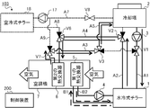
- FIG. 15 shows the flow path of the cooling water in the “normal cooling” operation mode.
- the flow path switching unit 240 transmits an instruction to the first valve V1 and the second valve V2, and switches the valve on the third cooling water channel A3 side in the first valve V1. Close the valve on the fourth cooling water channel A4 side in the second valve V2.
- the flow path switching unit 240 is configured such that the cooling water flowing through the first cooling water path A1 is not supplied to the third cooling water path A3 through the cooling water flow path. Are switched to a flow path that is supplied to the water-cooled chiller 1. Thereby, the cooling water circulates between the cooling tower 2 and the water-cooled chiller 1.
- the cold water cooled by the cooling water in the water-cooled chiller 1 is circulated between the water-cooled chiller 1 and the first heat exchanger 5 by the cold water pump 4.
- the first heat exchanger 5 exchanges heat between cold water and air, thereby reducing the temperature and humidity of the air, and supplying low-temperature and low-humidity air to the conditioned space. Thereby, the air-conditioned space is cooled.
- the air conditioning system 103 cools the air-conditioned space by heat exchange in the first heat exchanger 5.
- the cooling water channels A3 to A5, A7 to A9, the second heat exchanger 6, the cooling water pump 17, and the air cooling chiller 18 are not used.
- FIG. 16 shows a flow path of the cooling water in the operation mode of “first reheat dehumidification” executed in summer when the outside air temperature and the temperature of the cooling water are relatively high.
- the flow path switching unit 240 sends instructions to each of the three valves V1 to V3 to open all the valves in the first valve V1 and the second valve V2, And the valve by the side of the 5th cooling water channel A5 in the 3rd valve V3 is closed.
- the flow path switching unit 240 supplies a part of the cooling water flowing through the first cooling water path A1 to the second heat exchanger 6 via the third cooling water path A3.
- a part other than the part (that is, the remaining part) of the cooling water flowing through the first cooling water channel A1 is switched to the flow path supplied to the water-cooled chiller 1.
- the cooling water circulates between the cooling tower 2 and the water-cooled chiller 1 and between the cooling tower 2 and the second heat exchanger 6.
- the cold water cooled by the cooling water in the water-cooled chiller 1 is circulated between the water-cooled chiller 1 and the first heat exchanger 5 by the cold water pump 4.
- the first heat exchanger 5 reduces the temperature and humidity of the air by exchanging heat between the cold water generated by the water-cooled chiller 1 and the air.
- the second heat exchanger 6 exchanges heat between a part of the cooling water supplied from the cooling tower 2 and the air heat-exchanged with the cold water in the first heat exchanger 5, so that the air Reheat. Changes in the temperature and humidity of the air at this time are the same as in FIG.
- the air conditioning system 103 regenerates the conditioned space by the two-stage heat exchange between the first heat exchanger 5 and the second heat exchanger 6. Heat dehumidify.
- the cooling water channels A5, A7 to A9, the cooling water pump 17 and the air cooling chiller 18 are not used.
- FIG. 17 shows a flow path of the cooling water in the operation mode of “second reheat dehumidification” executed in the intermediate period or winter period when the outside air temperature and the cooling water temperature are relatively low.
- the flow path switching unit 240 transmits an instruction to each of the three valves V1 to V3 to close the valve on the third cooling water channel A3 side in the first valve V1,
- the valve on the cooling tower 2 side in the second valve V2 is closed, and the valve on the first valve V1 side in the third valve V3 is closed.
- the flow path switching unit 240 supplies all of the cooling water flowing through the first cooling water channel A1 to the water-cooled chiller 1, and the cooling water cooled by the water-cooled chiller 1 becomes the second cooling water channel A2.
- the cooling water supplied to the second heat exchanger 6 via the fourth cooling water channel A4 and heat-exchanged with the air in the second heat exchanger 6 is converted into the third cooling water channel A3 and the fifth cooling water channel A4. It switches to the flow path supplied to the cooling tower 2 via cooling water path A5. Accordingly, the cooling water circulates in the order of the cooling tower 2, the water-cooled chiller 1, and the second heat exchanger 6.
- the cold water cooled by the cooling water in the water-cooled chiller 1 is circulated between the water-cooled chiller 1 and the first heat exchanger 5 by the cold water pump 4.
- the first heat exchanger 5 reduces the temperature and humidity of the air by exchanging heat between the cold water generated by the water-cooled chiller 1 and the air.
- the second heat exchanger 6 exchanges heat between a part of the cooling water supplied from the cooling tower 2 and the air heat-exchanged with the cold water in the first heat exchanger 5, so that the air Reheat. Changes in the temperature and humidity of the air at this time are the same as in FIG.
- the air conditioning system 103 regenerates the conditioned space by the two-stage heat exchange between the first heat exchanger 5 and the second heat exchanger 6. Heat dehumidify.
- the cooling water channels A7 to A9, the cooling water pump 17 and the air cooling chiller 18 are not used.
- FIG. 18 shows the flow path of the cooling water in the “free cooling” operation mode that is executed when the temperature of the cooling water is sufficiently low in the winter or intermediate period.
- the flow path switching unit 240 transmits an instruction to each of the three valves V1 to V3, so that the water cooling chiller 1 side of the first valve V1 and the second valve V2 is on the side.
- the valve is closed, and the valve on the fifth cooling water channel A5 side in the third valve V3 is closed.
- the flow path switching unit 240 is configured such that the cooling water flowing through the first cooling water path A1 is not supplied to the water-cooled chiller 1 and all of the cooling water flowing through the first cooling water path A1 It switches to the flow path supplied to the 2nd heat exchanger 6 via 3rd cooling water path A3. Thereby, the cooling water circulates between the cooling tower 2 and the second heat exchanger 6.
- the air conditioning system 103 supplies the cooling water cooled by the outside air in the cooling tower 2 to the second heat exchanger 6 as it is to cool the air-conditioned space.
- the cooling water channels A5, A7 to A9, the water cooling chiller 1, the cooling water pump 4, the first heat exchanger 5, the cooling water pump 17 and the air cooling chiller 18 are not used.
- the “second cooling” is an operation mode in which the cooling capacity is insufficient in “free cooling”, but the cooling water is cooled by the air-cooled chiller 18 when a high cooling capacity is not required compared to “normal cooling”. is there.
- the operation mode of “second cooling” is executed, for example, when the outside air temperature is medium in the intermediate period.
- the air-cooled chiller 18 cools the cooling water cooled by the cooling tower.
- the air conditioning control unit 220 transmits an instruction to switch the flow path of the four-way valve to the air-cooled chiller 18 via the communication unit 204 to cool the cooling water.
- the flow path switching unit 240 supplies the cooling water cooled by the cooling tower 2 to the air-cooled chiller 18 via the seventh cooling water path A7.
- the cooling water cooled by the air-cooled chiller 18 is switched to a flow path that is supplied to the second heat exchanger 6 via the eighth cooling water path A8.
- the flow path switching unit 240 is configured such that the cooling water that has exchanged heat with the air in the second heat exchanger 6 is the third cooling water path A3 and the fifth cooling water path A5. The flow path is switched to the flow path supplied to the cooling tower 2 via the cooling water path A5.
- the fifth condition is a condition under which the air conditioning system 103 starts air conditioning in the “second cooling” operation mode. More specifically, the fifth condition is established when cooling is requested and the outside air temperature is lower than the third threshold value. The case where cooling is requested is when the request acquisition unit 210 acquires a request for starting cooling, or when the timing for starting the cooling determined in the operation schedule has arrived.
- the third threshold is a reference temperature for switching the operation mode from “normal cooling” to “second cooling”, and is set to 15 ° C. or 20 ° C., for example.
- the third threshold value is set to a temperature higher than the above-described second threshold value, which is a reference temperature for switching the operation mode to “free cooling”.
- the air conditioning system 103 performs cooling in the “second cooling” operation mode when the outside air temperature is higher than the second threshold and lower than the third threshold when cooling is requested, and the outside air temperature is When it is smaller than the threshold value of 2 (that is, when the above-described fourth condition is satisfied), the cooling is performed in the “free cooling” operation mode.
- FIG. 19 shows the flow path of the cooling water during the second cooling.
- the flow path switching unit 240 transmits an instruction to each of the six valves V1 to V3 and V6 to V8, so that all of the first valve V1 and the second valve V2 The valve is closed, the valve on the fifth cooling water channel A5 side in the third valve V3 is closed, the valve on the second valve V2 side in the sixth valve V6 is closed, and the ninth cooling water channel in the seventh valve V7 The A9 side valve is closed and the eighth valve V8 is opened.
- the second heat exchanger 6 Since the valve on the ninth cooling water channel A9 side in the seventh valve V7 is closed and the valve on the fifth cooling water channel A5 side in the third valve V3 is closed, the second heat exchanger 6 The output cooling water is supplied to the cooling tower 2 via the third cooling water channel A3 and the fifth cooling water channel A5. Thus, the cooling water circulates through the cooling tower 2, the air-cooled chiller 18 and the second heat exchanger 6 in this order.
- the temperature of the cooling water is lowered by absorbing heat to the outside air in the cooling tower 2, further lowered by being cooled in the air-cooled chiller 18, and in the second heat exchanger 6 It rises by cooling.
- the cooling water whose temperature has risen in the second heat exchanger 6 returns to the cooling tower 2 and is cooled again.
- the second heat exchanger 6 reduces the temperature and humidity of the air by exchanging heat between the cooling water and the air, and supplies low-temperature and low-humidity air to the air-conditioned space. Thereby, the air-conditioned space is cooled. During the second cooling, the water-cooled chiller 1, the cooling water pump 3, the cold water pump 4, and the first heat exchanger 5 are stopped.
- the air-conditioning system 103 saves energy compared to the “normal cooling” operation mode. be able to. Further, since the cooling water is cooled by the air-cooled chiller 18, the cooling can be performed with a higher cooling capacity than the “free cooling” operation mode.
- the air conditioning system 103 can also perform air conditioning in the “heating” operation mode. This will be described below.
- the air-cooled chiller 18 heats the cooling water to generate hot water.
- the air conditioning control unit 220 transmits an instruction to switch the flow path of the four-way valve to the air-cooled chiller 18 via the communication unit 204 to heat the cooling water.
- the flow path switching unit 240 passes through the cooling water flow path through the cooling water (hot water) heated by the air-cooled chiller 18 via the eighth cooling water path A8.
- the cooling water supplied to the heat exchanger 6 and cooled by the second heat exchanger 6 is switched to a flow path that is supplied to the air-cooled chiller 18 via the ninth cooling water path A9.
- the sixth condition is a condition in which the air conditioning system 103 starts air conditioning in the “heating” operation mode. More specifically, the sixth condition is satisfied when the request acquisition unit 210 acquires a request for starting heating, or when the timing for starting heating defined in the operation schedule has arrived.
- FIG. 20 shows the flow path of the cooling water during heating.
- the flow path switching unit 240 transmits an instruction to each of the sixth to eighth valves V6 to V8 and closes the valve on the second valve V2 side in the sixth valve V6.
- the valve on the first valve V1 side in the seventh valve V7 is closed, and the eighth valve V8 is closed. Further, since the first to third valves V1 to V3 are not used, the flow path switching unit 240 closes all these valves.
- the cooling water heated by the air-cooled chiller 18 is supplied to the second heat exchanger 6 by closing the valve on the second valve V2 side in the sixth valve V6.
- the cooling water heat-exchanged with air in the second heat exchanger 6 is air-cooled chiller. 18 is supplied.
- the cooling water circulates between the air-cooled chiller 18 and the second heat exchanger 6.
- the temperature of the cooling water rises by being heated in the air-cooled chiller 18, and the temperature is lowered by exchanging heat with air in the second heat exchanger 6.
- the cooling water whose temperature has decreased in the second heat exchanger 6 returns to the air-cooled chiller 18 and is heated again.
- the second heat exchanger 6 heats the air by exchanging heat between the heated cooling water and the air, and supplies high-temperature air to the air-conditioned space. Thereby, the air-conditioned space is heated.
- the air conditioning system 103 heats the air-conditioned space by circulating the hot water generated by the air-cooled chiller 18. During heating, the water-cooled chiller 1, the cooling tower 2, the cooling water pump 3, the cold water pump 4, and the first heat exchanger 5 are stopped.
- the air conditioning system 103 has a heating operation function in addition to the reheat dehumidification function and the free cooling function, so that it is possible to improve cost effectiveness and user convenience.
- the air conditioning system 101 according to the first embodiment and the air conditioning system 102 according to the second embodiment include “normal cooling”, “first reheat dehumidification”, “second reheat dehumidification”, and “ It was possible to air-condition in four operation modes of “free cooling”.
- the air conditioning system according to the present invention may not have the function of air conditioning in all of these operation modes.
- the air conditioning system may not have the function of “second reheat dehumidification”, may not have the function of “free cooling”, or may not have both functions.
- the air conditioning system may include only the functions of “normal cooling” and “first reheat dehumidification” among these four operation modes, or only the function of “first reheat dehumidification”. May be.
- the control device 200 may not include the temperature acquisition unit 230 that acquires the outside air temperature and the flow path switching unit 240 that switches the flow path of the cooling water.
- the temperature acquisition unit 230 acquires the outside air temperature.
- the temperature acquisition unit 230 may acquire the temperature of the cooling water output from the cooling tower 2.
- the temperature of the cooling water output from the cooling tower 2 is the temperature of the cooling water immediately after being cooled by exchanging heat with the outside air in the cooling tower 2. Since the cooling water is cooled by the outside air in the cooling tower 2, the temperature of the cooling water output from the cooling tower 2 has a large correlation with the outside air temperature.
- the temperature acquisition unit 230 acquires information on the temperature of the cooling water detected by the temperature sensor provided at the cooling water outlet in the cooling tower 2 via the communication unit 204. Then, the flow path switching unit 240 switches the flow path of the cooling water according to the operation mode acquired by the request acquisition unit 210 and the temperature of the cooling water acquired by the temperature acquisition unit 230.
- the eighth cooling water channel A8 from which the cooling water cooled or heated by the air-cooled chiller 18 is output is connected to the fourth cooling water channel A4, and the second heat exchanger 6
- the ninth cooling water channel A9 that guides the cooling water output from the air-cooled chiller 18 was connected to the third cooling water channel A3.
- the eighth cooling water channel A8 may be connected to the third cooling water channel A3, and the ninth cooling water channel A9 may be connected to the fourth cooling water channel A4.
- the cooling water cooled or heated by the air-cooled chiller 18 is supplied to the second heat exchanger 6 via the eighth cooling water channel A8 and the third cooling water channel A3.
- the cooling water output from the second heat exchanger 6 is transferred to the seventh cooling water passage A7 via the fourth cooling water passage A4 and the ninth cooling water passage A9 in the “heating” operation mode. It flows in and is supplied to the air-cooled chiller 18.
- the cooling water output from the second heat exchanger 6 passes to the cooling tower 2 via the fourth cooling water channel A4 and the second cooling water channel A2.
- the flow path switching unit 240 transmits instructions to the second valve V2, the sixth valve V6, and the seventh valve V7 to switch the flow path of the cooling water to such a flow path.
- control device 200 is installed outside the water-cooled chiller 1, the cooling tower 2, and the air conditioner 7, and has been described as an independent device.
- any of the control boards provided in the water-cooled chiller 1, the cooling tower 2, and the air conditioner 7 may function as the control device 200 described above.
- the control device described above is obtained by cooperation of a plurality of devices among the control board provided in the water-cooled chiller 1, the cooling tower 2 and the air conditioner 7 and the devices installed outside these. 200 may function.
- control unit 201 of the control device 200 the CPU executes a program stored in the ROM or the storage unit 202, whereby the request acquisition unit 210, the air conditioning control unit 220, the temperature acquisition unit 230, and the flow path. It functioned as each of the switching unit 240.
- the control unit 201 may be dedicated hardware.
- the dedicated hardware is, for example, a single circuit, a composite circuit, a programmed processor, an ASIC (Application Specific Integrated ⁇ Circuit), an FPGA (Field-Programmable Gate Array), or a combination thereof.
- ASIC Application Specific Integrated ⁇ Circuit
- FPGA Field-Programmable Gate Array
- each unit may be realized by dedicated hardware, and the other part may be realized by software or firmware.
- the control unit 201 can realize the above-described functions by hardware, software, firmware, or a combination thereof.
- the computer can also function as the control device 200 according to the present invention. is there.
- a program distribution method is arbitrary.
- a computer-readable record such as a CD-ROM (Compact Disk ROM), a DVD (Digital Versatile Disk), an MO (Magneto Optical Disk), or a memory card. It may be distributed by being stored in a medium or distributed via a communication network such as the Internet.
- the present invention can be suitably employed in an air conditioning system or the like.
Abstract
L'invention concerne un système de climatisation (101), dans lequel une colonne de refroidissement (2) refroidit de l'eau de refroidissement. Un dispositif source de chaleur génère de l'eau froide au moyen de l'eau de refroidissement refroidie par la colonne de refroidissement (2). Un trajet de circulation d'eau de refroidissement (A) met en circulation l'eau de refroidissement entre la colonne de refroidissement (2) et le dispositif source de chaleur. Un premier échangeur de chaleur (5) échange de la chaleur entre l'air et l'eau froide générée par un dispositif source de chaleur. Un trajet de circulation d'eau froide (B) met en circulation de l'eau froide entre le dispositif source de chaleur et le premier échangeur de chaleur (5). Un second échangeur de chaleur (6) échange de la chaleur entre une partie de l'eau de refroidissement refroidie par la colonne de refroidissement (2) et l'air amené à échanger de la chaleur avec l'eau froide dans le premier échangeur de chaleur (5). Un trajet de dérivation d'eau de refroidissement (A') guide, vers le second échangeur de chaleur (6), une partie de l'eau de refroidissement guidée de la colonne de refroidissement (2) au dispositif source de chaleur dans le trajet de circulation d'eau de refroidissement (A), et guide, vers le trajet de circulation d'eau de refroidissement (A), une partie de l'eau de refroidissement amenée à échanger de la chaleur avec de l'air dans le second échangeur de chaleur (6).
Priority Applications (5)
| Application Number | Priority Date | Filing Date | Title |
|---|---|---|---|
| EP16919578.1A EP3531034B1 (fr) | 2016-10-21 | 2016-10-21 | Système de climatisation |
| JP2018546132A JP6641500B2 (ja) | 2016-10-21 | 2016-10-21 | 空調システム |
| CN201680090079.9A CN109844413B (zh) | 2016-10-21 | 2016-10-21 | 空调系统 |
| PCT/JP2016/081356 WO2018073968A1 (fr) | 2016-10-21 | 2016-10-21 | Système de climatisation |
| US16/327,178 US11131476B2 (en) | 2016-10-21 | 2016-10-21 | Water cooled-type air conditioning system |
Applications Claiming Priority (1)
| Application Number | Priority Date | Filing Date | Title |
|---|---|---|---|
| PCT/JP2016/081356 WO2018073968A1 (fr) | 2016-10-21 | 2016-10-21 | Système de climatisation |
Publications (1)
| Publication Number | Publication Date |
|---|---|
| WO2018073968A1 true WO2018073968A1 (fr) | 2018-04-26 |
Family
ID=62018290
Family Applications (1)
| Application Number | Title | Priority Date | Filing Date |
|---|---|---|---|
| PCT/JP2016/081356 WO2018073968A1 (fr) | 2016-10-21 | 2016-10-21 | Système de climatisation |
Country Status (5)
| Country | Link |
|---|---|
| US (1) | US11131476B2 (fr) |
| EP (1) | EP3531034B1 (fr) |
| JP (1) | JP6641500B2 (fr) |
| CN (1) | CN109844413B (fr) |
| WO (1) | WO2018073968A1 (fr) |
Cited By (3)
| Publication number | Priority date | Publication date | Assignee | Title |
|---|---|---|---|---|
| WO2020035946A1 (fr) * | 2018-08-17 | 2020-02-20 | 三菱電機株式会社 | Machine à source de chaleur et unité de refroidissement naturel |
| WO2020035945A1 (fr) * | 2018-08-17 | 2020-02-20 | 三菱電機株式会社 | Unité de refroidissement naturel |
| KR20200082462A (ko) * | 2018-12-28 | 2020-07-08 | 서울대학교산학협력단 | 각각의 냉방공간에 설치된 제습 냉방기를 포함하는 건물용 제습냉방 시스템 |
Families Citing this family (4)
| Publication number | Priority date | Publication date | Assignee | Title |
|---|---|---|---|---|
| JP6835141B2 (ja) * | 2019-05-31 | 2021-02-24 | ダイキン工業株式会社 | 空調システム |
| US11441797B1 (en) * | 2019-09-04 | 2022-09-13 | Altaire Systems LLC | Systems and methods for commercial airstream pretreatment |
| CN110715431B (zh) * | 2019-10-25 | 2021-07-06 | 厦门烟草工业有限责任公司 | 换热控制系统及其控制方法和装置 |
| CN112856723B (zh) * | 2021-01-07 | 2022-07-12 | 丁一 | 冷却水泵控制方法、装置、控制器及制冷系统 |
Citations (7)
| Publication number | Priority date | Publication date | Assignee | Title |
|---|---|---|---|---|
| US5170635A (en) * | 1990-05-21 | 1992-12-15 | Honeywell Inc. | Defrost for air handling system utilizing direct expansion cooling |
| JP2002061911A (ja) * | 2000-08-17 | 2002-02-28 | Takasago Thermal Eng Co Ltd | 電算機室の冷房方法 |
| JP2004316980A (ja) * | 2003-04-14 | 2004-11-11 | Hitachi Plant Eng & Constr Co Ltd | 空気調和装置 |
| JP2005061647A (ja) * | 2003-08-18 | 2005-03-10 | Sanki Eng Co Ltd | 空調システム |
| JP2005207712A (ja) * | 2004-01-26 | 2005-08-04 | Techno Ryowa Ltd | 空気調和装置 |
| JP2008215679A (ja) * | 2007-03-01 | 2008-09-18 | Sanki Eng Co Ltd | 空気調和設備 |
| JP2014037936A (ja) * | 2012-08-20 | 2014-02-27 | Takasago Thermal Eng Co Ltd | 冷却システム |
Family Cites Families (9)
| Publication number | Priority date | Publication date | Assignee | Title |
|---|---|---|---|---|
| JPS5852924A (ja) * | 1981-09-22 | 1983-03-29 | Sumitomo Electric Ind Ltd | 冷媒の凝縮熱を利用した空気調和装置 |
| JP2979061B2 (ja) * | 1991-01-31 | 1999-11-15 | 三機工業株式会社 | 自然冷却空調装置 |
| CN1240975C (zh) * | 2003-11-06 | 2006-02-08 | 上海交通大学 | 基于固体吸附制冷机的微型冷热电三联供系统 |
| JP4652371B2 (ja) * | 2007-05-08 | 2011-03-16 | 株式会社Nttファシリティーズ | 空気調和システム及びその運転方法 |
| CN100545521C (zh) * | 2007-11-01 | 2009-09-30 | 上海交通大学 | 太阳能与建筑一体化复合能量系统 |
| JP5902053B2 (ja) * | 2012-06-28 | 2016-04-13 | 株式会社日立製作所 | 冷却システム及び冷却方法 |
| US20140298834A1 (en) * | 2013-04-03 | 2014-10-09 | William A. Gast, Jr. | Method and system for hybrid cooling systems |
| CN103912943A (zh) * | 2014-03-27 | 2014-07-09 | 成信绿集成股份有限公司 | 一种温湿度独立控制及免费冷热湿的系统及方法 |
| CN204513625U (zh) * | 2014-12-22 | 2015-07-29 | 丛旭日 | 一种冷却塔式热力再生溶液除湿机组 |
-
2016
- 2016-10-21 US US16/327,178 patent/US11131476B2/en active Active
- 2016-10-21 EP EP16919578.1A patent/EP3531034B1/fr active Active
- 2016-10-21 WO PCT/JP2016/081356 patent/WO2018073968A1/fr unknown
- 2016-10-21 JP JP2018546132A patent/JP6641500B2/ja active Active
- 2016-10-21 CN CN201680090079.9A patent/CN109844413B/zh active Active
Patent Citations (7)
| Publication number | Priority date | Publication date | Assignee | Title |
|---|---|---|---|---|
| US5170635A (en) * | 1990-05-21 | 1992-12-15 | Honeywell Inc. | Defrost for air handling system utilizing direct expansion cooling |
| JP2002061911A (ja) * | 2000-08-17 | 2002-02-28 | Takasago Thermal Eng Co Ltd | 電算機室の冷房方法 |
| JP2004316980A (ja) * | 2003-04-14 | 2004-11-11 | Hitachi Plant Eng & Constr Co Ltd | 空気調和装置 |
| JP2005061647A (ja) * | 2003-08-18 | 2005-03-10 | Sanki Eng Co Ltd | 空調システム |
| JP2005207712A (ja) * | 2004-01-26 | 2005-08-04 | Techno Ryowa Ltd | 空気調和装置 |
| JP2008215679A (ja) * | 2007-03-01 | 2008-09-18 | Sanki Eng Co Ltd | 空気調和設備 |
| JP2014037936A (ja) * | 2012-08-20 | 2014-02-27 | Takasago Thermal Eng Co Ltd | 冷却システム |
Cited By (5)
| Publication number | Priority date | Publication date | Assignee | Title |
|---|---|---|---|---|
| WO2020035946A1 (fr) * | 2018-08-17 | 2020-02-20 | 三菱電機株式会社 | Machine à source de chaleur et unité de refroidissement naturel |
| WO2020035945A1 (fr) * | 2018-08-17 | 2020-02-20 | 三菱電機株式会社 | Unité de refroidissement naturel |
| JPWO2020035945A1 (ja) * | 2018-08-17 | 2021-04-30 | 三菱電機株式会社 | フリークーリングユニット |
| KR20200082462A (ko) * | 2018-12-28 | 2020-07-08 | 서울대학교산학협력단 | 각각의 냉방공간에 설치된 제습 냉방기를 포함하는 건물용 제습냉방 시스템 |
| KR102152390B1 (ko) * | 2018-12-28 | 2020-09-04 | 주식회사 휴마스터 | 각각의 냉방공간에 설치된 제습 냉방기를 포함하는 건물용 제습냉방 시스템 |
Also Published As
| Publication number | Publication date |
|---|---|
| CN109844413B (zh) | 2021-04-06 |
| JPWO2018073968A1 (ja) | 2019-03-14 |
| JP6641500B2 (ja) | 2020-02-05 |
| EP3531034B1 (fr) | 2020-09-02 |
| CN109844413A (zh) | 2019-06-04 |
| EP3531034A4 (fr) | 2019-10-30 |
| US11131476B2 (en) | 2021-09-28 |
| US20200018513A1 (en) | 2020-01-16 |
| EP3531034A1 (fr) | 2019-08-28 |
Similar Documents
| Publication | Publication Date | Title |
|---|---|---|
| WO2018073968A1 (fr) | Système de climatisation | |
| US11512879B2 (en) | Method and apparatus for charge compensator reheat valve | |
| US20150369498A1 (en) | Air-conditioning apparatus | |
| US11306928B2 (en) | Method and apparatus for re-heat circuit operation | |
| JP2017150778A (ja) | 地中熱を利用する除湿再熱空調システム | |
| US10989456B2 (en) | Method and apparatus for common manifold charge compensator | |
| WO2014132433A1 (fr) | Dispositif de climatisation | |
| WO2011099059A1 (fr) | Dispositif de climatisation | |
| US20150159935A1 (en) | Apparatus with dehumidification and defrosting abilities and controlling method thereof | |
| WO2018066089A1 (fr) | Machine de réfrigération et système de climatisation | |
| EP2339267B1 (fr) | Appareil à cycle de réfrigération, climatiseur d'air alimenté en eau chaude de type pompe à chaleur et unité d'extérieur correspondante | |
| KR20150009201A (ko) | 히트펌프 시스템 및 그 제어방법 | |
| JP5827717B2 (ja) | ヒートポンプ付ファンコイル式放射空調パネル用空調機 | |
| JP2005283058A (ja) | 再熱除湿型空気調和機 | |
| CN114026367B (zh) | 空调系统 | |
| KR102265011B1 (ko) | 냉난방기 온도조절 자동제어 시스템 | |
| KR102493156B1 (ko) | 공기 조화기 및 그 제어 방법 | |
| JP2022124107A (ja) | 温水暖房システム | |
| US20210140700A1 (en) | Control scheme for automatic fan mode for use with variable refrigerant flow systems | |
| JP2023091400A (ja) | 空気調和システム | |
| KR100942542B1 (ko) | 혼합 열교환기 및 이를 이용한 glp전용 공기조화기 | |
| JP2020024058A (ja) | 複合熱源ヒートポンプ装置 | |
| JP2004028522A (ja) | 空気調和機 | |
| KR20080079475A (ko) | 멀티형 공기조화기 시스템 | |
| KR20080105581A (ko) | 공기조화기 시스템 |
Legal Events
| Date | Code | Title | Description |
|---|---|---|---|
| ENP | Entry into the national phase |
Ref document number: 2018546132 Country of ref document: JP Kind code of ref document: A |
|
| 121 | Ep: the epo has been informed by wipo that ep was designated in this application |
Ref document number: 16919578 Country of ref document: EP Kind code of ref document: A1 |
|
| NENP | Non-entry into the national phase |
Ref country code: DE |
|
| ENP | Entry into the national phase |
Ref document number: 2016919578 Country of ref document: EP Effective date: 20190521 |