WO2018073968A1 - 空調システム - Google Patents
空調システム Download PDFInfo
- Publication number
- WO2018073968A1 WO2018073968A1 PCT/JP2016/081356 JP2016081356W WO2018073968A1 WO 2018073968 A1 WO2018073968 A1 WO 2018073968A1 JP 2016081356 W JP2016081356 W JP 2016081356W WO 2018073968 A1 WO2018073968 A1 WO 2018073968A1
- Authority
- WO
- WIPO (PCT)
- Prior art keywords
- cooling water
- cooling
- heat exchanger
- air
- flow path
- Prior art date
Links
Images


Classifications
-
- F—MECHANICAL ENGINEERING; LIGHTING; HEATING; WEAPONS; BLASTING
- F24—HEATING; RANGES; VENTILATING
- F24F—AIR-CONDITIONING; AIR-HUMIDIFICATION; VENTILATION; USE OF AIR CURRENTS FOR SCREENING
- F24F3/00—Air-conditioning systems in which conditioned primary air is supplied from one or more central stations to distributing units in the rooms or spaces where it may receive secondary treatment; Apparatus specially designed for such systems
- F24F3/001—Air-conditioning systems in which conditioned primary air is supplied from one or more central stations to distributing units in the rooms or spaces where it may receive secondary treatment; Apparatus specially designed for such systems in which the air treatment in the central station takes place by means of a heat-pump or by means of a reversible cycle
-
- F—MECHANICAL ENGINEERING; LIGHTING; HEATING; WEAPONS; BLASTING
- F24—HEATING; RANGES; VENTILATING
- F24F—AIR-CONDITIONING; AIR-HUMIDIFICATION; VENTILATION; USE OF AIR CURRENTS FOR SCREENING
- F24F11/00—Control or safety arrangements
- F24F11/70—Control systems characterised by their outputs; Constructional details thereof
- F24F11/80—Control systems characterised by their outputs; Constructional details thereof for controlling the temperature of the supplied air
- F24F11/83—Control systems characterised by their outputs; Constructional details thereof for controlling the temperature of the supplied air by controlling the supply of heat-exchange fluids to heat-exchangers
- F24F11/84—Control systems characterised by their outputs; Constructional details thereof for controlling the temperature of the supplied air by controlling the supply of heat-exchange fluids to heat-exchangers using valves
-
- F—MECHANICAL ENGINEERING; LIGHTING; HEATING; WEAPONS; BLASTING
- F24—HEATING; RANGES; VENTILATING
- F24F—AIR-CONDITIONING; AIR-HUMIDIFICATION; VENTILATION; USE OF AIR CURRENTS FOR SCREENING
- F24F3/00—Air-conditioning systems in which conditioned primary air is supplied from one or more central stations to distributing units in the rooms or spaces where it may receive secondary treatment; Apparatus specially designed for such systems
- F24F3/12—Air-conditioning systems in which conditioned primary air is supplied from one or more central stations to distributing units in the rooms or spaces where it may receive secondary treatment; Apparatus specially designed for such systems characterised by the treatment of the air otherwise than by heating and cooling
- F24F3/14—Air-conditioning systems in which conditioned primary air is supplied from one or more central stations to distributing units in the rooms or spaces where it may receive secondary treatment; Apparatus specially designed for such systems characterised by the treatment of the air otherwise than by heating and cooling by humidification; by dehumidification
-
- F—MECHANICAL ENGINEERING; LIGHTING; HEATING; WEAPONS; BLASTING
- F24—HEATING; RANGES; VENTILATING
- F24F—AIR-CONDITIONING; AIR-HUMIDIFICATION; VENTILATION; USE OF AIR CURRENTS FOR SCREENING
- F24F5/00—Air-conditioning systems or apparatus not covered by F24F1/00 or F24F3/00, e.g. using solar heat or combined with household units such as an oven or water heater
- F24F5/0003—Exclusively-fluid systems
-
- F—MECHANICAL ENGINEERING; LIGHTING; HEATING; WEAPONS; BLASTING
- F24—HEATING; RANGES; VENTILATING
- F24F—AIR-CONDITIONING; AIR-HUMIDIFICATION; VENTILATION; USE OF AIR CURRENTS FOR SCREENING
- F24F5/00—Air-conditioning systems or apparatus not covered by F24F1/00 or F24F3/00, e.g. using solar heat or combined with household units such as an oven or water heater
- F24F5/0046—Air-conditioning systems or apparatus not covered by F24F1/00 or F24F3/00, e.g. using solar heat or combined with household units such as an oven or water heater using natural energy, e.g. solar energy, energy from the ground
-
- F—MECHANICAL ENGINEERING; LIGHTING; HEATING; WEAPONS; BLASTING
- F24—HEATING; RANGES; VENTILATING
- F24F—AIR-CONDITIONING; AIR-HUMIDIFICATION; VENTILATION; USE OF AIR CURRENTS FOR SCREENING
- F24F11/00—Control or safety arrangements
- F24F11/30—Control or safety arrangements for purposes related to the operation of the system, e.g. for safety or monitoring
- F24F11/46—Improving electric energy efficiency or saving
-
- F—MECHANICAL ENGINEERING; LIGHTING; HEATING; WEAPONS; BLASTING
- F24—HEATING; RANGES; VENTILATING
- F24F—AIR-CONDITIONING; AIR-HUMIDIFICATION; VENTILATION; USE OF AIR CURRENTS FOR SCREENING
- F24F11/00—Control or safety arrangements
- F24F11/62—Control or safety arrangements characterised by the type of control or by internal processing, e.g. using fuzzy logic, adaptive control or estimation of values
- F24F11/63—Electronic processing
- F24F11/65—Electronic processing for selecting an operating mode
- F24F11/67—Switching between heating and cooling modes
-
- F—MECHANICAL ENGINEERING; LIGHTING; HEATING; WEAPONS; BLASTING
- F24—HEATING; RANGES; VENTILATING
- F24F—AIR-CONDITIONING; AIR-HUMIDIFICATION; VENTILATION; USE OF AIR CURRENTS FOR SCREENING
- F24F3/00—Air-conditioning systems in which conditioned primary air is supplied from one or more central stations to distributing units in the rooms or spaces where it may receive secondary treatment; Apparatus specially designed for such systems
- F24F3/12—Air-conditioning systems in which conditioned primary air is supplied from one or more central stations to distributing units in the rooms or spaces where it may receive secondary treatment; Apparatus specially designed for such systems characterised by the treatment of the air otherwise than by heating and cooling
- F24F3/14—Air-conditioning systems in which conditioned primary air is supplied from one or more central stations to distributing units in the rooms or spaces where it may receive secondary treatment; Apparatus specially designed for such systems characterised by the treatment of the air otherwise than by heating and cooling by humidification; by dehumidification
- F24F2003/144—Air-conditioning systems in which conditioned primary air is supplied from one or more central stations to distributing units in the rooms or spaces where it may receive secondary treatment; Apparatus specially designed for such systems characterised by the treatment of the air otherwise than by heating and cooling by humidification; by dehumidification by dehumidification only
-
- F—MECHANICAL ENGINEERING; LIGHTING; HEATING; WEAPONS; BLASTING
- F24—HEATING; RANGES; VENTILATING
- F24F—AIR-CONDITIONING; AIR-HUMIDIFICATION; VENTILATION; USE OF AIR CURRENTS FOR SCREENING
- F24F5/00—Air-conditioning systems or apparatus not covered by F24F1/00 or F24F3/00, e.g. using solar heat or combined with household units such as an oven or water heater
- F24F5/0007—Air-conditioning systems or apparatus not covered by F24F1/00 or F24F3/00, e.g. using solar heat or combined with household units such as an oven or water heater cooling apparatus specially adapted for use in air-conditioning
- F24F5/0017—Air-conditioning systems or apparatus not covered by F24F1/00 or F24F3/00, e.g. using solar heat or combined with household units such as an oven or water heater cooling apparatus specially adapted for use in air-conditioning using cold storage bodies, e.g. ice
- F24F2005/0025—Air-conditioning systems or apparatus not covered by F24F1/00 or F24F3/00, e.g. using solar heat or combined with household units such as an oven or water heater cooling apparatus specially adapted for use in air-conditioning using cold storage bodies, e.g. ice using heat exchange fluid storage tanks
-
- F—MECHANICAL ENGINEERING; LIGHTING; HEATING; WEAPONS; BLASTING
- F24—HEATING; RANGES; VENTILATING
- F24F—AIR-CONDITIONING; AIR-HUMIDIFICATION; VENTILATION; USE OF AIR CURRENTS FOR SCREENING
- F24F2203/00—Devices or apparatus used for air treatment
- F24F2203/02—System or Device comprising a heat pump as a subsystem, e.g. combined with humidification/dehumidification, heating, natural energy or with hybrid system
- F24F2203/021—Compression cycle
-
- F—MECHANICAL ENGINEERING; LIGHTING; HEATING; WEAPONS; BLASTING
- F24—HEATING; RANGES; VENTILATING
- F24F—AIR-CONDITIONING; AIR-HUMIDIFICATION; VENTILATION; USE OF AIR CURRENTS FOR SCREENING
- F24F5/00—Air-conditioning systems or apparatus not covered by F24F1/00 or F24F3/00, e.g. using solar heat or combined with household units such as an oven or water heater
- F24F5/0007—Air-conditioning systems or apparatus not covered by F24F1/00 or F24F3/00, e.g. using solar heat or combined with household units such as an oven or water heater cooling apparatus specially adapted for use in air-conditioning
- F24F5/0017—Air-conditioning systems or apparatus not covered by F24F1/00 or F24F3/00, e.g. using solar heat or combined with household units such as an oven or water heater cooling apparatus specially adapted for use in air-conditioning using cold storage bodies, e.g. ice
Definitions
- the present invention relates to an air conditioning system.
- a technology is known in which cold water is cooled by cooling water and air-conditioning is performed by exchanging heat between the cold water and air.
- Patent Document 1 discloses an air conditioning system including a cold water circuit that supplies cold water generated by a heat source device to an air conditioner, and a cooling water circuit that discharges exhaust heat recovered by the cold water circuit to the atmosphere through a cooling tower. is doing.
- the air conditioning system disclosed in Patent Literature 1 performs free cooling by bypassing the heat source device and supplying the cooling water directly to the air conditioner when the temperature of the cooling water becomes equal to or lower than the threshold value. As a result, energy can be saved when the outside air temperature decreases.
- Patent Document 1 can perform free cooling during a period when the outside air temperature is low, but cannot perform free cooling during a period when the outside air temperature is high. Therefore, the period during which free cooling can be implemented is limited. In view of such a situation, there is a demand for air conditioning using cooling water more effectively.
- the present invention has been made to solve the above-described problems, and provides an air conditioning system and the like that can effectively use cooling water in air conditioning using cooling water and cold water. Objective.
- a cooling tower for cooling the cooling water;
- a heat source machine that generates cold water by the cooling water cooled by the cooling tower;
- a cooling water circulation path for circulating the cooling water between the cooling tower and the heat source unit;
- a first heat exchanger for exchanging heat between the cold water generated by the heat source unit and air;
- a cold water circulation path for circulating the cold water between the heat source unit and the first heat exchanger;
- a second heat exchanger for exchanging heat between a part of the cooling water cooled by the cooling tower and the air heat-exchanged with the cold water by the first heat exchanger;
- the cooling water guided from the cooling tower to the heat source unit is guided to the second heat exchanger, and the cooling is heat-exchanged with the air by the second heat exchanger.
- a cooling water branch path for guiding the part of the water to the cooling water circulation path.
- the cooling water cooled by the cooling tower is circulated between the cooling tower and the heat source unit, the cold water generated by the heat source unit is circulated between the heat source unit and the first heat exchanger, In the heat exchanger, the heat exchange between the cold water generated by the heat source machine and the air is conducted, a part of the cooling water led from the cooling tower to the heat source machine is led to the second heat exchanger, and the second heat In the exchanger, heat is exchanged between a part of the cooling water cooled by the cooling tower and the air heat-exchanged with the cold water by the first heat exchanger. Therefore, according to the present invention, cooling water can be effectively used in air conditioning using cooling water and cold water.
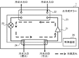
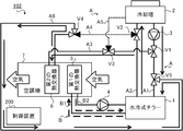
- the air conditioning system 101 is a system that air-conditions a space to be air-conditioned (hereinafter referred to as “air-conditioned space”) using the cooling water cooled by the cooling tower 2.
- Air conditioning refers to adjusting the temperature, humidity, cleanliness, airflow, or the like of air in an air-conditioned space, and specifically includes heating, cooling, dehumidification, humidification, air purification, and the like.
- the air-conditioned space is an internal space such as a general house, apartment house, office building, facility, or factory.
- an air conditioning system 101 includes a water-cooled chiller 1 that generates cold water, a cooling tower 2 that cools cooling water with outside air, a cooling water pump 3 that circulates cooling water, and cold water that circulates cooling water.
- the pump 4 the first heat exchanger 5 that exchanges heat between air and cold water, the second heat exchanger 6 that exchanges heat between air and cooling water, and the first heat exchanger 5
- the air conditioner 7 including the second heat exchanger 6, the three valves (first valve V1, second valve V2, and third valve V3) for switching the flow path of the cooling water, and the entire system are controlled.
- a control device 200 a control device 200.
- the air conditioning system 101 circulates the cooling water as a cooling water or cooling water flow path between the components, the cooling water circulation path A for circulating the cooling water, the cooling water branch path A ′ branched from the cooling water circulation path A, and the cooling water.
- the air-conditioning system 101 is a so-called secondary refrigerant circulation type or indirect cooling system that uses cooling water as a primary refrigerant and cold water as a secondary refrigerant.
- the water-cooled chiller 1 is a device that generates cold water.
- Cold water is a medium for cooling air in an air-conditioned space.
- the water-cooled chiller 1 functions as a heat source device that exchanges heat between the cooling water and the cold water and cools the cold water using the cooling water as a cold heat source.
- the water-cooled chiller 1 is a heat pump chiller using, for example, CO 2 (carbon dioxide) or HFC (hydrofluorocarbon) as a refrigerant.
- the water-cooled chiller 1 is installed outside the air-conditioned space, for example, in the same site as the air-conditioned space.
- the water-cooled chiller 1 includes a compressor 21, a first refrigerant-water heat exchanger 22, an expansion device 23, a second refrigerant-water heat exchanger 24, and an annular structure. And a refrigerant circuit 25 connected to the control board 26.
- the refrigerant circuit 25 is a circuit in which the refrigerant circulates, and is also called a heat pump or a refrigeration cycle.
- the compressor 21 compresses the refrigerant flowing through the refrigerant circuit 25 and increases the temperature and pressure of the refrigerant.
- the compressor 21 includes an inverter circuit that can change the capacity (the amount of delivery per unit) according to the operating frequency (the number of revolutions).
- the compressor 21 changes the operating frequency according to the control value instructed from the control board 26.
- the refrigerant sucked into the compressor 21 is compressed and discharged into a high-temperature and high-pressure gas refrigerant.
- the first refrigerant-water heat exchanger 22 exchanges heat between the refrigerant flowing through the refrigerant circuit 25 and the cooling water supplied from the cooling tower 2.
- the first refrigerant-water heat exchanger 22 is a plate-type or double-tube type heat exchanger, for example.
- the high-temperature and high-pressure refrigerant compressed by the compressor 21 is condensed by exchanging heat with the cooling water in the first refrigerant-water heat exchanger 22 and changed into a high-pressure liquid.
- the refrigerant condenses in the first refrigerant-water heat exchanger 22 the temperature of the cooling water rises because the cooling water is given heat.
- the expansion device 23 expands the refrigerant flowing through the refrigerant circuit 25 and lowers the temperature and pressure of the refrigerant.
- the expansion device 23 changes the opening degree of the valve according to the control value instructed from the control board 26 and adjusts the amount of decompression of the refrigerant.
- the refrigerant changed to a high-pressure liquid in the first refrigerant-water heat exchanger 22 is decompressed to a low-temperature and low-pressure two-phase refrigerant by the expansion device 23.
- the second refrigerant-water heat exchanger 24 exchanges heat between the refrigerant flowing through the refrigerant circuit 25 and the cold water supplied from the air conditioner 7.
- the second refrigerant-water heat exchanger 24 is a heat exchanger such as a plate type or a double pipe type.
- the refrigerant decompressed by the expansion device 23 evaporates by exchanging heat with cold water in the second refrigerant-water heat exchanger 24, and changes to a low-pressure gas.
- the refrigerant that has changed to a low-pressure gas returns to the compressor 21 and is compressed again into a high-temperature and high-pressure gas.
- the refrigerant evaporates in the second refrigerant-water heat exchanger 24, the temperature of the cold water decreases because heat is taken away.
- the control board 26 includes a CPU, a ROM, a RAM, a communication interface, a readable / writable non-volatile semiconductor memory, and the like, although not shown.
- the control board 26 is communicably connected to the compressor 21 and the expansion device 23 via a communication line (not shown).
- the control board 26 is communicably connected to the control device 200 via a communication line (not shown).
- the control board 26 controls the operations of the compressor 21 and the expansion device 23 in accordance with the instruction transmitted from the control device 200.
- the cooling tower 2 is equipment for cooling the cooling water.
- the cooling water is a medium for cooling the cold water with the water-cooled chiller 1.
- the cooling tower 2 includes a blower that blows outside air, and cools the cooling water by exchanging heat between the cooling water and the outside air. More specifically, the cooling tower 2 is a method in which the cooling water is directly contacted with the outside air to evaporate (open type), or the heat medium that is in contact with the outside air is circulated to indirectly cool the cooling water with the outside air.
- the cooling water is cooled by a method of contacting and evaporating (sealed type). As described above, the cooling tower 2 cools the cooling water by bringing the outside air into direct or indirect contact with the cooling water.
- the cooling tower 2 is installed outside the air-conditioned space, for example, in the same site as the air-conditioned space.
- the cooling tower 2 includes a control board including a CPU, a ROM, a RAM, a communication interface, a readable / writable non-volatile semiconductor memory, and the like, although not shown.
- the control board is communicably connected to the control device 200 via a communication line (not shown). The control board controls the operation of the cooling tower 2 according to the instruction transmitted from the control device 200.
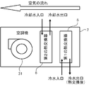
- the air conditioner 7 is a facility that air-conditions the air-conditioned space.
- the air conditioner 7 is also referred to as AHU (air handling unit).
- the air conditioner 7 is installed in a place where air conditioned in the conditioned space can be supplied.
- the air conditioner 7 is installed, for example, on the upper part of the wall of the air-conditioned space or on the ceiling.
- the air conditioner 7 may be installed in a dedicated machine room connected by a duct to a plurality of rooms, each of which is an air-conditioned space.
- the air conditioner 7 includes a first heat exchanger 5 that exchanges heat between air and cold water, and a second heat exchanger 6 that exchanges heat between air and cooling water. And an air blowing device 31 for blowing air.
- Both the first heat exchanger 5 and the second heat exchanger 6 are well-known heat exchangers that exchange heat between air and water.
- the first heat exchanger 5 exchanges heat between the cold water generated by the water-cooled chiller 1 and air.
- the second heat exchanger 6 is installed on the downstream side of the first heat exchanger 5, and a part of the cooling water cooled by the cooling tower 2 and the first heat exchanger 5 chilled water and heat Exchange heat with the exchanged air.
- the air sucked into the air conditioner 7 by the air blower 31 first passes through the first heat exchanger 5 and exchanges heat with cold water.
- the air heat-exchanged with the cold water in the first heat exchanger 5 further passes through the second heat exchanger 6 and exchanges heat with the cooling water.
- the air sucked into the air conditioner 7 is supplied to the conditioned space after heat exchange is performed twice.
- the air conditioner 7 includes a control board including a CPU, a ROM, a RAM, a communication interface, a readable / writable nonvolatile semiconductor memory, and the like, although not shown.
- the control board is communicably connected to the control device 200 via a communication line (not shown).
- the control board controls the operation of the air conditioner 7 according to the instruction transmitted from the control device 200.
- the cooling water circulation path A is provided between the cooling tower 2 and the water-cooled chiller 1, and circulates the cooling water between the cooling tower 2 and the water-cooled chiller 1.
- the cooling water circulation path A includes a first cooling water path A1 and a second cooling water path A2 connected to the cooling tower 2 and the water cooling chiller 1, respectively.
- the first cooling water channel A1 is a cooling water supply channel (outward channel) that guides the cooling water cooled by the cooling tower 2 to the water-cooled chiller 1.
- the second cooling water channel A ⁇ b> 2 is a cooling water reflux channel (return channel) that guides the cooling water that has been cooled by the water-cooled chiller 1 to the cooling tower 2.
- the cooling water branch path A ′ is provided between the cooling water circulation path A and the second heat exchanger 6, and a part of the cooling water flowing through the cooling water circulation path A is branched to provide the second heat exchanger 6. It is a branch path to supply to.
- the cooling water branch A ′ guides a part of the cooling water led from the cooling tower 2 to the water-cooled chiller 1 in the cooling water circulation path A to the second heat exchanger 6. A part of the exchanged cooling water is guided to the cooling water circuit A.
- the cooling water branch A ′ includes a third cooling water passage A3 connected to the middle of the first cooling water passage A1 and the second heat exchanger 6, and a second heat exchange between the middle of the second cooling water passage A2. And a fourth cooling water channel A4 connected to the vessel 6.
- the third cooling water channel A3 guides a part of the cooling water flowing through the first cooling water channel A1 to the second heat exchanger 6.
- the fourth cooling water channel A4 guides the cooling water heat-exchanged with the air by the second heat exchanger 6 to the second cooling water channel A2.
- the cooling water branch A ′ includes a fifth cooling water channel A5 connected to the middle of the third cooling water channel A3 and the cooling tower 2.
- the fifth cooling water channel A5 is a bypass channel that guides the cooling water flowing through the third cooling water channel A3 to the cooling tower 2 without passing through the cooling water circuit A.
- the cooling water circulation path A is provided with a cooling water pump 3.
- the cooling water pump 3 sends out the cooling water generated by the cooling tower 2 and circulates through the cooling water circulation path A and the cooling water branch path A ′.
- the cooling water pump 3 includes an inverter circuit, and changes the amount of cooling water to be sent out by adjusting the drive rotation speed according to the control value instructed from the control device 200.
- the cooling water sent out from the cooling tower 2 by the cooling water pump 3 returns to the water cooling chiller 1 through one or both of the water cooling chiller 1 and the first heat exchanger 5.
- the cooling water circulation path A is provided with a first valve V1, a second valve V2, and a third valve V3.
- Each of the first valve V1, the second valve V2, and the third valve V3 is an electric three-way valve that opens and closes the valve by a known method such as an electromagnetic type or an electric type.
- Each of the first valve V1, the second valve V2, and the third valve V3 changes the flow path of the cooling water by switching the opening and closing of the valves in accordance with a control command from the control device 200.
- the first valve V1 allows the cooling water output from the cooling tower 2 to the first cooling water channel A1 to flow to the water-cooled chiller 1, the second heat exchanger 6, or the water-cooled chiller 1. And whether to flow to both the second heat exchanger 6.
- the second valve V2 includes the cooling water output from the water-cooled chiller 1 to the second cooling water passage A2, and the cooling water output from the second heat exchanger 6 to the fourth cooling water passage A4. Only one of the above is switched to the cooling tower 2 or both are switched to the cooling tower 2.
- the third valve V3 switches whether or not to guide the cooling water flowing through the third cooling water channel A3 to the fifth cooling water channel A5.
- the cold water circulation path B is provided between the water-cooled chiller 1 and the first heat exchanger 5 and circulates cold water between the water-cooled chiller 1 and the first heat exchanger 5.
- the cold water circulation path B includes a first cold water path B1 and a second cold water path B2 connected to the water-cooled chiller 1 and the first heat exchanger 5, respectively.
- the first cold water passage B ⁇ b> 1 is a cold water supply passage (outward water passage) that guides the cold water generated by the water-cooled chiller 1 to the first heat exchanger 5.
- the second cold water passage B2 is a cold water recirculation passage (return water passage) that guides the cold water heat-exchanged with the air by the first heat exchanger 5 to the water-cooled chiller 1.
- a cold water pump 4 is provided in the cold water circulation path B.
- the cold water pump 4 sends out the cold water generated by the water-cooled chiller 1 and circulates the cold water circulation path B.
- the chilled water pump 4 includes an inverter circuit, and changes the amount of chilled water to be sent out by adjusting the drive rotation speed according to the control value instructed from the control device 200.
- the cold water sent out from the water-cooled chiller 1 by the cold water pump 4 returns to the water-cooled chiller 1 through the first heat exchanger 5.
- Control device 200 controls the entire air conditioning system 101 in an integrated manner.
- the control device 200 is installed, for example, inside the air-conditioned space or at an appropriate place in the same site as the air-conditioned space.
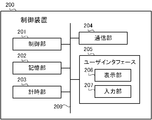
- FIG. 4 shows the hardware configuration of the control device 200.
- the control device 200 includes a control unit 201, a storage unit 202, a time measuring unit 203, a communication unit 204, and a user interface 205. These units are connected via a bus 209.
- the control unit 201 includes a CPU, a ROM, a RAM, and the like, although not shown.
- the CPU is also called a central processing unit, a central processing unit, a processor, a microprocessor, a microcomputer, a DSP (Digital Signal Processor), or the like.
- the CPU reads a program and data stored in the ROM, and performs overall control of the control device 200 using the RAM as a work area.
- the storage unit 202 is a non-volatile semiconductor memory such as a flash memory, an EPROM (Erasable Programmable ROM), or an EEPROM (Electrically Erasable Programmable ROM), and serves as a so-called secondary storage device (auxiliary storage device). .
- the storage unit 202 stores various programs and data used by the control unit 201 to perform various processes, and various data generated or acquired by the control unit 201 performing various processes.
- the timekeeping unit 203 includes an RTC (Real Time Clock), and is a time measuring device that keeps time while the power of the control device 200 is off.
- RTC Real Time Clock
- the communication unit 204 is an interface for communicating with an external device.
- the communication unit 204 is connected to each of the water-cooled chiller 1, the cooling tower 2, the cooling water pump 3, the cold water pump 4, the air conditioner 7, the first valve V1, the second valve V2, and the third valve V3, wired or It is connected so as to be communicable wirelessly, and communicates with these components in accordance with a known communication standard.
- the communication unit 204 is connected to a local area network and a wide area network, and communicates with devices outside the air conditioning system 101.
- the user interface 205 includes a display unit 206 and an input unit 207.
- the display unit 206 is a display device such as an LCD (Liquid Crystal Display) panel, an organic EL, or an LED (Light Emitting Diode).
- the input unit 207 is an input device such as a touch panel, a touch pad, a switch, or various press buttons.
- the user interface 205 accepts various operations from the user via the input unit 207 and displays various display images via the display unit 206.
- the display unit 206 and the input unit 207 may be configured as a touch panel (touch screen) in which these are superimposed on each other.
- the control apparatus 200 may include a user interface 205 (display unit 206 and input unit 207) in the apparatus main body.
- the user interface 205 is not included in the apparatus main body, and a remote controller separated from the apparatus main body is used as the user interface 205. It may be functioning.
- the control device 200 communicates with the remote control via the communication unit 204.
- the communication unit 204 transmits a signal indicating a display image on the display unit 206 of the remote control, and receives a signal indicating the operation content received from the user by the input unit 207 of the remote control.
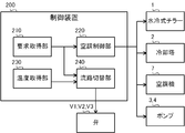
- the control unit 201 functionally includes a request acquisition unit 210, an air conditioning control unit 220, a temperature acquisition unit 230, and a flow path switching unit 240.
- Each of these functions is realized by software, firmware, or a combination of software and firmware.
- Software and firmware are described as programs and stored in the ROM or the storage unit 202.
- Each function is realized by the CPU executing a program stored in the ROM or the storage unit 202.
- the request acquisition unit 210 acquires an operation request for the air conditioning system 101.
- the user can input a request such as start of air conditioning, end of air conditioning, change of set temperature, or change of operation mode by operating the input unit 207 or from the outside via the communication unit 204. .
- the request acquisition unit 210 acquires the request input from the user in this way.
- the request acquisition unit 210 acquires an operation request issued according to a predetermined operation schedule via the communication unit 204.
- the request acquisition unit 210 is realized by the control unit 201 cooperating with the communication unit 204 or the input unit 207.
- the air conditioning system 101 can be air-conditioned in the “cooling” or “reheat dehumidification” operation mode, as will be described in detail later. More specifically, there are “normal cooling” and “free cooling” as operation modes of “cooling”, and “first reheat dehumidification” and “second reheat” as operation modes of “reheat dehumidification”. There is “heat dehumidification”. The user can select a desired operation mode from among the operation modes of “cooling” or “reheat dehumidification”. The request acquisition unit 210 acquires the operation mode selected in this way.
- the air conditioning control unit 220 controls the air conditioning operation in the air conditioning system 101. Specifically, the air conditioning control unit 220 communicates with each of the water-cooled chiller 1, the cooling tower 2, the cooling water pump 3, the cold water pump 4, and the air conditioner 7 via the communication unit 204, and operates each device. Send instructions.
- the air conditioning control unit 220 is realized by the control unit 201 cooperating with the communication unit 204.
- the air conditioning control unit 220 transmits an operation start instruction for the water-cooled chiller 1 to the control board 26 to drive the compressor 21 and the expansion device 23.
- the water-cooled chiller 1 generates cold water.
- the air conditioning control unit 220 drives the cooling water pump 3 and the cold water pump 4 to circulate the cooling water and the cold water.
- the air conditioning control unit 220 transmits an operation start instruction to the cooling tower 2 and the air conditioner 7, causes the cooling tower 2 to cool the cooling water, and causes the air conditioner 7 to start air conditioning.
- the temperature acquisition unit 230 acquires the outside air temperature.
- the outside air temperature is outside the air-conditioned space and means the temperature of outdoor air.
- the outside air temperature is detected by a temperature sensor such as a thermistor or a thermocouple provided outdoors.
- the temperature acquisition unit 230 acquires information on the outside air temperature detected by the temperature sensor via the communication unit 204.
- the temperature acquisition unit 230 is realized when the control unit 201 cooperates with the communication unit 204.
- the flow path switching unit 240 switches the flow path of the cooling water in the cooling water circulation path A and the cooling water branch path A ′.
- the cooling water flow path is a path through which the cooling water circulates in the cooling water circulation path A and the cooling water branch path A ′.
- the flow path switching unit 240 transmits an instruction to switch opening / closing of the valve to each of the first valve V1, the second valve V2, and the third valve V3 via the communication unit 204, thereby cooling the three-way valve. Switch the direction of water flow. Thereby, the flow path switching unit 240 changes the flow path of the cooling water.
- the flow path switching unit 240 is realized by the control unit 201 cooperating with the communication unit 204.
- the flow path switching unit 240 switches the cooling water flow path according to the operation mode acquired by the request acquisition unit 210 and the outside air temperature acquired by the temperature acquisition unit 230.
- the air conditioning system 101 operates in each operation mode of “normal cooling”, “first reheat dehumidification”, “second reheat dehumidification”, and “free cooling” will be described.
- the normal cooling is an operation mode in which the air-conditioned space is cooled by cooling air with the cold water generated by the water-cooled chiller 1.
- the flow path switching unit 240 switches the flow path of the cooling water to a flow path in which all the cooling water flowing through the first cooling water path A1 is supplied to the water-cooled chiller 1.
- the first condition is a condition in which the air conditioning system 101 starts air conditioning in the “normal cooling” operation mode. More specifically, the first condition is satisfied when the request acquisition unit 210 acquires a cooling start request or when the timing for starting the cooling determined in the operation schedule arrives.
- FIG. 6 shows the flow path of the cooling water during normal cooling.
- the flow path switching unit 240 transmits an instruction to the first valve V1 and the second valve V2, and switches the valve on the third cooling water channel A3 side in the first valve V1. Close the valve on the fourth cooling water channel A4 side in the second valve V2. By closing the valve on the third cooling water passage A3 side in the first valve V1, the cooling water cooled in the cooling tower 2 is not supplied to the cooling water branch A ′ and the second heat exchanger 6, All of this is supplied to the water-cooled chiller 1.
- the cooling water after cooling the cold water with the water-cooled chiller 1 is the cooling water branch A ′ and the second heat exchanger 6. Are all supplied to the cooling tower 2. In this way, the cooling water circulates between the cooling tower 2 and the water-cooled chiller 1. In such a flow path, the temperature of the cooling water decreases by absorbing heat to the outside air in the cooling tower 2 and increases by cooling the cold water in the water-cooled chiller 1.
- the cold water cooled by the cooling water in the water-cooled chiller 1 is circulated between the water-cooled chiller 1 and the first heat exchanger 5 by the cold water pump 4. At this time, the temperature of the cold water decreases by exchanging heat with the cooling water in the water-cooled chiller 1 and increases by exchanging heat with the air in the first heat exchanger 5.
- the first heat exchanger 5 exchanges heat between cold water and air, thereby reducing the temperature and humidity of the air and supplying low-temperature and low-humidity air to the air-conditioned space. Thereby, the air-conditioned space is cooled.
- the second heat exchanger 6 is not used because the cooling water does not flow through the cooling water branch A ′.
- the air conditioning system 101 cools the air-conditioned space by heat exchange in the first heat exchanger 5.
- FIG. 6 the direction in which the three-way valve is closed is shown in black. Further, in the cooling water circulation path A and the cooling water branching path A ′, the flow paths through which the cooling water flows are indicated by solid lines, and the flow paths through which the cooling water does not flow are indicated by dotted lines. The same applies to the subsequent drawings.
- first reheat dehumidification is an operation mode in which air is cooled with cold water to reduce the humidity, and then air is reheated with cooling water and supplied to the air-conditioned space.
- the air conditioning system 101 can be operated in two operation modes of “first reheat dehumidification” and “second reheat dehumidification” as reheat dehumidification.
- the “first reheat dehumidification” is an operation mode that is executed in summer when the outside air temperature and the cooling water temperature are relatively high
- the “second reheat dehumidification” is the outside air temperature and the cooling water temperature. This is an operation mode executed in a relatively low intermediate period or winter period.
- the flow path switching unit 240 is configured such that a part of the cooling water flowing through the first cooling water path A1 passes through the third cooling water path A3 through the second cooling water path A3. A part other than the part (that is, the remaining part) of the cooling water supplied to the heat exchanger 6 and flowing through the first cooling water path A1 is switched to a flow path supplied to the water-cooled chiller 1.
- the second condition is a condition in which the air conditioning system 101 starts air conditioning in the operation mode of “first reheat dehumidification”. Specifically, the second condition is established when reheat dehumidification is requested and when the outside air temperature acquired by the temperature acquisition unit 230 is larger than the first threshold.
- the case where reheat dehumidification is requested is when the request acquisition unit 210 acquires a request for starting reheat dehumidification, or when the timing for starting reheat dehumidification defined in the operation schedule has arrived.
- the first threshold value is a reference temperature for switching between “first reheat dehumidification” and “second reheat dehumidification”, and is set in advance to, for example, 25 ° C. or 30 ° C.
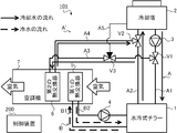
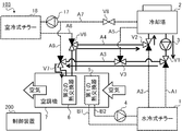
- FIG. 7 shows the flow path of the cooling water during the first reheat dehumidification.
- the flow path switching unit 240 sends instructions to each of the three valves V1 to V3 to open all the valves in the first valve V1 and the second valve V2, And the valve by the side of the 5th cooling water channel A5 in the 3rd valve V3 is closed.
- the cooling water cooled in the cooling tower 2 is divided and supplied to both the water-cooled chiller 1 and the second heat exchanger 6.
- the first part of the cooling water cooled by the cooling tower 2 is supplied to the water-cooled chiller 1, and the second part other than the first part is supplied to the second heat exchanger 6.
- the first valve after the chilled water is cooled by the water-cooled chiller 1 by opening all the valves in the second valve V2 and closing the valve on the fifth cooling water channel A5 side in the third valve V3.
- the cooling water in the part and the cooling water in the second part after heat exchange with the air in the second heat exchanger 6 are merged in the second valve V2, mixed, and returned to the water-cooled chiller 1. In this way, the cooling water circulates between the cooling tower 2 and the water-cooled chiller 1 and between the cooling tower 2 and the second heat exchanger 6.
- the temperature of the cooling water decreases by absorbing heat to the outside air in the cooling tower 2, increases by cooling the cold water in the water-cooled chiller 1, and air in the second heat exchanger 6.
- the temperature decreases by reheating the.
- the cooling water of the first part whose temperature has been increased by the water-cooled chiller 1 is cooled by mixing the cooling water of the second part whose temperature has been decreased by the second heat exchanger 6 with the second valve V2.
- the temperature drops to some extent. Therefore, the load for cooling the cooling water in the cooling tower 2 is reduced, and energy consumption can be saved.
- the cold water cooled by the cooling water in the water-cooled chiller 1 is circulated between the water-cooled chiller 1 and the first heat exchanger 5 by the cold water pump 4. At this time, the temperature of the cold water decreases by exchanging heat with the cooling water in the water-cooled chiller 1 and increases by exchanging heat with the air in the first heat exchanger 5.
- the first heat exchanger 5 reduces the temperature and humidity of the air by exchanging heat between the cold water generated by the water-cooled chiller 1 and the air. By being cooled to cold water by the first heat exchanger 5, the temperature of the air is lower than the temperature of the cooling water supplied from the cooling tower 2.
- the second heat exchanger 6 exchanges heat between a part of the cooling water supplied from the cooling tower 2 and the air heat-exchanged with the cold water in the first heat exchanger 5, so that the air Reheat.
- FIG. 8 shows a change in air temperature and humidity when passing through the first heat exchanger 5 and the second heat exchanger 6 on an air diagram.
- both the temperature and humidity of the air are relatively high near the inlet of the first heat exchanger 5, that is, before the air flows into the air conditioner 7.
- the temperature and humidity of the air near the outlet of the first heat exchanger 5 are reduced by being cooled to cold water by the first heat exchanger 5.
- the temperature of the air near the exit of the second heat exchanger 6 increases by being reheated to the cooling water by the second heat exchanger 6.
- the medium-temperature and low-humidity air generated in this way is supplied to the conditioned space.
- the air conditioning system 101 regenerates the conditioned space by the two-stage heat exchange between the first heat exchanger 5 and the second heat exchanger 6. Heat dehumidify.
- the flow path switching unit 240 supplies all of the cooling water flowing through the first cooling water path A1 to the water-cooled chiller 1 through the cooling water flow path.
- the cooling water cooled is supplied to the second heat exchanger 6 via the second cooling water channel A2 and the fourth cooling water channel A4, and exchanged heat with air in the second heat exchanger 6.
- the cooling water is switched to a flow path that is supplied to the cooling tower 2 via the third cooling water path A3 and the fifth cooling water path A5.
- the third condition is a condition in which the air conditioning system 101 starts air conditioning in the operation mode of “second reheat dehumidification”. Specifically, the third condition is established when reheat dehumidification is requested and when the outside air temperature acquired by the temperature acquisition unit 230 is smaller than the first threshold.
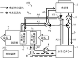
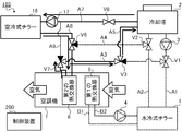
- FIG. 9 shows the flow path of the cooling water during the second reheat dehumidification.
- the flow path switching unit 240 transmits an instruction to each of the three valves V1 to V3 to close the valve on the third cooling water channel A3 side in the first valve V1,
- the valve on the cooling tower 2 side in the second valve V2 is closed, and the valve on the first valve V1 side in the third valve V3 is closed.
- the cooling water cooled in the cooling tower 2 is not supplied to the cooling water branch A ′ and the second heat exchanger 6, All of this is supplied to the water-cooled chiller 1.
- the cooling water after cooling the cooling water with the water-cooled chiller 1 is not supplied to the cooling tower 2, and all of the cooling water is the fourth cooling. It is supplied to the second heat exchanger 6 via the water channel A4. Further, by closing the valve on the first valve V1 side in the third valve V3, the cooling water after the heat exchange with the air in the second heat exchanger 6 is performed in the third cooling water channel A3 and the fifth cooling water channel A3. It returns to the cooling tower 2 via the cooling water channel A5. Thus, the cooling water circulates in the order of the cooling tower 2, the water-cooled chiller 1, and the second heat exchanger 6.
- the temperature of the cooling water decreases by absorbing heat to the outside air in the cooling tower 2, increases by cooling the cold water in the water-cooled chiller 1, and air in the second heat exchanger 6.
- the temperature decreases by reheating the.
- the temperature of the cooling water whose temperature has increased in the water-cooled chiller 1 decreases to some extent before returning to the cooling tower 2 due to reheating of the air in the second heat exchanger 6. Therefore, the load for cooling the cooling water in the cooling tower 2 is reduced, and energy consumption can be saved.
- the cold water cooled by the cooling water in the water-cooled chiller 1 is circulated between the water-cooled chiller 1 and the first heat exchanger 5 by the cold water pump 4. At this time, the temperature of the cold water decreases by exchanging heat with the cooling water in the water-cooled chiller 1 and increases by exchanging heat with the air in the first heat exchanger 5.
- the first heat exchanger 5 reduces the temperature and humidity of the air by exchanging heat between the cold water generated by the water-cooled chiller 1 and the air. By cooling to cold water with the 1st heat exchanger 5, the temperature of air falls rather than the temperature of the cooling water after cooling cold water with the water cooling type chiller 1.
- FIG. The second heat exchanger 6 exchanges heat between the cooling water after cooling the cold water with the water-cooled chiller 1 and the air heat-exchanged with the cold water with the first heat exchanger 5, Reheat the air. Changes in the temperature and humidity of the air at this time are the same as in FIG.
- the air conditioning system 101 regenerates the conditioned space by the two-stage heat exchange between the first heat exchanger 5 and the second heat exchanger 6.
- Heat dehumidify In “first reheat dehumidification”, the cooling water is supplied directly from the cooling tower 2 to the second heat exchanger 6, whereas in “second reheat dehumidification”, the cooling water is a water-cooled chiller. After being heated by the exhaust heat at 1, it is supplied to the second heat exchanger 6. Therefore, “second reheat dehumidification” is an effective operation mode when the temperature of the cooling water is relatively lower than “first reheat dehumidification”.
- the air conditioning system 101 When reheat dehumidification is requested, the air conditioning system 101 operates by changing the operation mode of “first reheat dehumidification” and the operation mode of “second reheat dehumidification” according to the outside air temperature. .
- the flow path switching unit 240 switches the flow path of the cooling water according to such a change in the operation mode.
- Free cooling is an operation mode in which cooling is performed with cooling water cooled by the cooling tower 2 without using the water-cooled chiller 1 when the temperature of the cooling water is sufficiently low in the winter or intermediate period.
- the flow path switching unit 240 is configured so that the cooling water flowing through the first cooling water path A1 is not supplied to the water-cooled chiller 1 and the first cooling water path A1 is passed through the cooling water flow path. All the flowing cooling water is switched to a flow path that is supplied to the second heat exchanger 6 via the third cooling water path A3.
- the fourth condition is a condition in which the air conditioning system 101 starts air conditioning in the “free cooling” operation mode. Specifically, the fourth condition is established when cooling is requested and the outside air temperature acquired by the temperature acquisition unit 230 is smaller than the second threshold.
- the case where cooling is requested is when the request acquisition unit 210 acquires a request for starting cooling, or when the timing for starting the cooling determined in the operation schedule has arrived.
- the second threshold is a reference temperature for switching the operation mode from “normal cooling” to “free cooling”, and is set in advance to 5 ° C. or 10 ° C., for example.
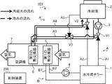
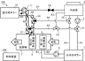
- Fig. 10 shows the flow path of the cooling water during free cooling.
- the flow path switching unit 240 transmits an instruction to each of the three valves V1 to V3, so that the water cooling chiller 1 side of the first valve V1 and the second valve V2 is on the side.
- the valve is closed, and the valve on the fifth cooling water channel A5 side in the third valve V3 is closed.
- the cooling water cooled by the cooling tower 2 is not supplied to the water-cooled chiller 1, all of which passes through the third cooling water channel A3. Then, it is supplied to the second heat exchanger 6.
- the cooling water after heat exchange with air in the second heat exchanger 6 is not supplied to the water-cooled chiller 1, All of this is supplied to the cooling tower 2.
- the cooling water circulates between the cooling tower 2 and the second heat exchanger 6. In such a flow path, the temperature of the cooling water decreases by absorbing heat to the outside air in the cooling tower 2 and increases by cooling the air in the second heat exchanger 6.
- the second heat exchanger 6 reduces the temperature and humidity of the air by exchanging heat between the cooling water and the air, and supplies low-temperature and low-humidity air to the air-conditioned space. Thereby, the air-conditioned space is cooled. During free cooling, the water-cooled chiller 1, the cold water pump 4, and the first heat exchanger 5 are stopped.
- the air conditioning system 101 supplies the cooling water cooled by the outside air in the cooling tower 2 to the second heat exchanger 6 as it is to cool the conditioned space. Since the water-cooled chiller 1, the cold water pump 4 and the first heat exchanger 5 are not used, energy consumption can be saved.
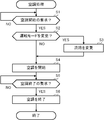
- the flow of air conditioning processing executed in the control device 200 of the air conditioning system 101 configured as described above will be described with reference to the flowchart shown in FIG.
- the air conditioning process illustrated in FIG. 11 is executed as needed by the control unit 201 in a state where power is supplied to the air conditioning system 101 and the air conditioning system 101 can be air conditioned.
- the control unit 201 first determines whether or not a request for starting air conditioning has been acquired (step S1). More specifically, the control unit 201 determines whether or not an input of an air conditioning start request has been received from the user via the input unit 207 or the communication unit 204. Further, the control unit 201 determines that the request for starting air conditioning has been acquired also when the timing for starting air conditioning predetermined in the operation schedule has arrived. In step S ⁇ b> 1, the control unit 201 functions as the request acquisition unit 210.
- step S1 When the request for starting air conditioning has not been acquired (step S1; NO), the control unit 201 stops the process at step S1 and waits until the request for starting air conditioning is acquired.
- step S2 determines whether the operation mode of the air conditioning system 101 should be changed (step S2). For example, the control unit 201 determines that the operation mode should be changed when a request for changing the operation mode is acquired from the user or when the outside air temperature satisfies a condition for switching the operation mode.
- step S ⁇ b> 2 the control unit 201 functions as the request acquisition unit 210 and the temperature acquisition unit 230.
- step S3 When changing the operation mode (step S2; YES), the control unit 201 changes the flow path of the cooling water (step S3). If demonstrating it concretely, the control part 201 will transmit the instruction
- step S2 when the operation mode is not changed (step S2; NO), the control unit 201 skips the process of step S3.
- step S4 the control unit 201 starts air conditioning (step S4). More specifically, the control unit 201 transmits an operation start instruction to the water-cooled chiller 1, the cooling tower 2, the cooling water pump 3, the cold water pump 4, and the air conditioner 7 via the communication unit 204. In step S ⁇ b> 4, the control unit 201 functions as the air conditioning control unit 220.
- control unit 201 determines whether or not a request for air conditioning termination has been acquired (step S5). More specifically, the control unit 201 determines whether or not an input of an air conditioning end request has been received from the user via the input unit 207 or the communication unit 204. Further, the control unit 201 determines that the request for air conditioning termination has been acquired also when the timing for terminating air conditioning predetermined in the operation schedule has come. In step S ⁇ b> 5, the control unit 201 functions as the request acquisition unit 210.
- step S5 When the request for air conditioning end has not been acquired (step S5; NO), the control unit 201 stops the process at step S5 and continues air conditioning until the request for air conditioning end is acquired.
- step S6 when the air conditioning end request is acquired (step S5; YES), the control unit 201 ends the air conditioning (step S6). More specifically, the control unit 201 transmits an operation end instruction to the water-cooled chiller 1, the cooling tower 2, the cooling water pump 3, the cold water pump 4, and the air conditioner 7 via the communication unit 204. In step S ⁇ b> 6, the control unit 201 functions as the air conditioning control unit 220. Thus, the air conditioning process shown in FIG. 11 ends.
- the air conditioning system 101 includes the cooling tower A ′ that is branched from the cooling water circulation path A ′ that circulates the cooling water between the cooling tower 2 and the water-cooled chiller 1.
- a part of the cooling water led from 2 to the water-cooled chiller 1 is supplied to the second heat exchanger 6. Since the air is reheated using the heat of the cooling water without requiring a dedicated heat source device for reheating, energy consumption is saved and costs are reduced.
- the cooling water can be used effectively even when the outside air temperature at which free cooling cannot be performed is relatively high. Since the cooling water branch path A ′ for branching the cooling water to the air conditioner 7 can be used not only for free cooling but also for reheat dehumidification, cost effectiveness for the addition of equipment can be enhanced.
- the air conditioning system 101 can switch the operation modes of normal cooling, first reheat dehumidification, second reheat dehumidification, and free cooling depending on the situation. As a result, it is possible to effectively use the cooling water in various situations for air conditioning, and to improve user convenience.
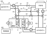
- FIG. 12 shows an outline of the air conditioning system 102 according to the second embodiment.
- the air conditioning system 102 includes a water-cooled chiller 1, a cooling tower 2, a cooling water pump 3, a cold water pump 4, a first heat exchanger 5, a second heat exchanger 6, an air conditioner 7, A cooling water circulation path A, a cooling water branch path A ′, a cooling water circulation path B, a first valve V 1, a second valve V 2, a third valve V 3, and a control device 200 are provided. Since each of these configurations is the same as that of the first embodiment, description thereof is omitted.
- the air conditioning system 102 includes a sixth cooling water channel A6 that guides a part of the cooling water heat-exchanged with air by the second heat exchanger 6 to the first cooling water channel A1, and the cooling water. And a fourth valve V4 and a fifth valve V5 for switching the flow paths.
- the sixth cooling water channel A6 is a position between the branch position of the first cooling water channel A1 to the third cooling water channel A3 (that is, the position where the first valve V1 is provided) and the water-cooled chiller 1. It is connected to the middle of the fourth cooling water channel A4.
- a fourth valve V4 is provided at a branch position of the fourth cooling water path A4 to the sixth cooling water path A6, and a branch position of the first cooling water path A1 to the sixth cooling water path A6 is provided at the branch position.
- a fifth valve V5 is provided.
- Each of the fourth valve V4 and the fifth valve V5 is a three-way valve that opens and closes the valve by a known method such as an electromagnetic type or an electric type.
- the fourth valve V4 switches whether or not to supply the cooling water flowing through the fourth cooling water channel A4 to the sixth cooling water channel A6 by opening and closing the valve according to the control command from the flow path switching unit 240.
- the fifth valve V5 switches whether or not to supply the cooling water flowing through the sixth cooling water channel A6 to the first cooling water channel A1 by opening and closing the valve according to the control command from the flow path switching unit 240.
- the air conditioning system 102 can perform air conditioning in four operation modes of “normal cooling”, “first reheat dehumidification”, “second reheat dehumidification”, and “free cooling”.
- the flow path switching unit 240 transmits an instruction to switch opening / closing of the valves to each of the five valves V1 to V5 via the communication unit 204 in accordance with the operation mode executed by the air conditioning system 102, thereby allowing the flow of the cooling water to flow. Switch the road.
- the three operation modes of “normal cooling”, “second reheat dehumidification”, and “free cooling” are the same as in the first embodiment.
- the flow path switching unit 240 closes the valve on the sixth cooling water channel A6 side in the fourth valve V4, and the sixth valve in the fifth valve V5.
- the valve on the cooling water channel A6 side is closed.
- the flow path of the cooling water is the same as in the first embodiment. Therefore, description of these three operation modes is omitted.
- the flow path switching unit 240 is configured such that a part of the cooling water flowing through the first cooling water path A1 passes through the third cooling water path A3 through the second cooling water path A3.
- a part (that is, the remaining part) other than a part of the cooling water that is supplied to the heat exchanger 6 and flows through the first cooling water passage A1 is supplied to the water-cooled chiller 1 and air is supplied to the second heat exchanger 6 by air.
- a part of the cooling water heat-exchanged with the first cooling water channel A6 and the first cooling water channel A1 is switched to the flow channel supplied to the water-cooled chiller 1.
- the second condition is a condition in which the air conditioning system 102 starts air conditioning in the operation mode of “first reheat dehumidification”. Specifically, the second condition is established when reheat dehumidification is requested and when the outside air temperature acquired by the temperature acquisition unit 230 is larger than the first threshold.
- FIG. 13 shows the flow path of the cooling water during the first reheat dehumidification.
- the flow path switching unit 240 sends instructions to each of the five valves V1 to V5 to open all the valves in the first valve V1 and the fifth valve V5,
- the valve on the fourth cooling water channel A4 side in the second valve V2 is closed
- the valve on the fifth cooling water channel A5 side in the third valve V3 is closed
- the second valve V2 side in the fourth valve V4 Close the valve.
- the cooling water cooled by the cooling tower 2 is divided and supplied to both the water-cooled chiller 1 and the second heat exchanger 6.
- the first part of the cooling water cooled by the cooling tower 2 is supplied to the water-cooled chiller 1, and the second part other than the first part is supplied to the second heat exchanger 6.
- the cooling water after cooling the cold water with the water-cooled chiller 1 is the cooling water branch A ′ and the second heat exchanger 6. Are all supplied to the cooling tower 2.
- the second heat exchanger 6 to the fourth valve
- the cooling water of the second part output to the cooling water channel A4 is supplied to the first cooling water channel A1 via the sixth cooling water channel A6.
- the cooling water in the second part that has flowed in from the sixth cooling water passage A6 in the fifth valve V5 and has exchanged heat with air in the second heat exchanger 6 is divided in the first valve V1. 1 is combined with the cooling water of part 1 and supplied to the water-cooled chiller 1.
- the temperature of the cooling water decreases by absorbing heat to the outside air in the cooling tower 2, increases by cooling the cold water in the water-cooled chiller 1, and air in the second heat exchanger 6. The temperature is further lowered by reheating. Therefore, the temperature of the cooling water flowing into the water-cooled chiller 1 from the second heat exchanger 6 via the sixth cooling water channel A6 is lower than the temperature of the cooling water cooled by the cooling tower 2. In other words, cooling water having a temperature lower than that of the cooling water cooled by the cooling tower 2 is supplied to the water-cooled chiller 1.
- the cold water cooled by the cooling water in the water-cooled chiller 1 is circulated between the water-cooled chiller 1 and the first heat exchanger 5 by the cold water pump 4. At this time, the temperature of the cold water decreases by exchanging heat with the cooling water in the water-cooled chiller 1 and increases by exchanging heat with the air in the first heat exchanger 5.
- the first heat exchanger 5 reduces the temperature and humidity of the air by exchanging heat between the cold water generated by the water-cooled chiller 1 and the air.
- the second heat exchanger 6 exchanges heat between the cooling water after cooling the cold water with the water-cooled chiller 1 and the air heat-exchanged with the cold water with the first heat exchanger 5. Changes in the temperature and humidity of the air at this time are the same as in FIG.
- the temperature of the cooling water flowing into the water-cooled chiller 1 can be lowered while achieving the effects in the first embodiment. Therefore, the cooling efficiency of the water-cooled chiller 1 is improved, and energy consumption can be saved. Thereby, even if the temperature of the cooling water is particularly high, the cold water can be efficiently cooled by the water-cooled chiller 1.
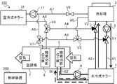
- FIG. 14 shows an outline of the air conditioning system 103 according to the third embodiment.
- the air conditioning system 103 includes a water-cooled chiller 1, a cooling tower 2, a cooling water pump 3, a cold water pump 4, a first heat exchanger 5, a second heat exchanger 6, an air conditioner 7, A cooling water circulation path A, a cooling water branch path A ′, a cooling water circulation path B, a first valve V 1, a second valve V 2, a third valve V 3, and a control device 200 are provided. Since each of these configurations is the same as that of the first embodiment, description thereof is omitted.
- the air conditioning system 103 includes a cooling water pump 17 that circulates cooling water, an air-cooled chiller 18 that cools or heats the cooling water, and a seventh cooling water channel that guides the cooling water to the air-cooled chiller 18.
- A7, the eighth cooling water channel A8 for guiding the cooling water cooled or heated by the air-cooled chiller 18 to the second heat exchanger 6, and the cooling water heat-exchanged with the air by the second heat exchanger 6 are air-cooled.
- a ninth cooling water passage A9 that leads to the chiller 18 and a sixth valve V6, a seventh valve V7, and an eighth valve V8 that switch the cooling water flow path are provided.
- the air-cooled chiller 18 is a device that cools or heats the cooling water by exchanging heat between the outside air and the cooling water.
- the air-cooled chiller 18 is a heat pump chiller using, for example, CO 2 (carbon dioxide) or HFC (hydrofluorocarbon) as a refrigerant.
- the air-cooled chiller 18 is installed, for example, outside the air-conditioned space and in the same site as the air-conditioned space.
- the water-cooled chiller 1 functions as a first heat source device that cools the cold water, whereas the air-cooled chiller 18 functions as a second heat source device that cools or heats the cooling water.
- the air-cooled chiller 18 includes a compressor that compresses the refrigerant, a four-way valve that switches the refrigerant flow path, a refrigerant-air heat exchanger that exchanges heat between the refrigerant and the outside air, and a refrigerant.
- the refrigerant circuit is a circuit through which the refrigerant circulates, and is also called a heat pump or a refrigeration cycle.
- the control board includes a CPU, a ROM, a RAM, a communication interface, a readable / writable nonvolatile semiconductor memory, and the like.
- the control board is communicably connected to the control device 200 via a communication line (not shown).
- the control board controls the operation of the air-cooled chiller 18 in accordance with the instruction transmitted from the control device 200.
- the control board switches the flow path of the four-way valve so that the refrigerant discharged from the compressor flows into the refrigerant-air heat exchanger, and drives the expansion device and the compressor.
- the compressor is driven, the refrigerant discharged from the compressor passes through the four-way valve, flows into the refrigerant-air heat exchanger, exchanges heat with the outside air, and condenses.
- the condensed refrigerant is depressurized by the expansion device, then flows into the refrigerant-water heat exchanger, exchanges heat with the cooling water, and evaporates.
- the evaporated refrigerant passes through the four-way valve and is sucked into the compressor again.
- the low-temperature refrigerant flows into the refrigerant-water heat exchanger, whereby the cooling water passing therethrough is cooled.
- the control board switches the flow path of the four-way valve so that the refrigerant discharged from the compressor flows into the refrigerant-water heat exchanger, and drives the expansion device and the compressor.
- the compressor When the compressor is driven, the refrigerant discharged from the compressor passes through the four-way valve, flows into the refrigerant-water heat exchanger, exchanges heat with the cooling water, and condenses.
- the condensed refrigerant is decompressed by the expansion device, then flows into the refrigerant-air heat exchanger, and evaporates by exchanging heat with the outside air.
- the evaporated refrigerant passes through the four-way valve and is sucked into the compressor again. In this way, when the high-temperature refrigerant flows into the refrigerant-water heat exchanger, the cooling water passing therethrough is heated.
- the seventh cooling water channel A ⁇ b> 7 is connected to the cooling tower 2 and the air-cooled chiller 18.
- a cooling water pump 17 is provided in the seventh cooling water channel A7.
- the cooling water pump 17 sends out and circulates the cooling water generated by the cooling tower 2.
- the cooling water pump 17 includes an inverter circuit, and changes the amount of cooling water to be sent out by adjusting the drive rotation speed according to the control value instructed from the control device 200.
- the cooling water pump 3 is called a first cooling water pump, and the cooling water pump 17 is called a second cooling water pump.
- an eighth valve V8 is provided in the middle of the seventh cooling water channel A7.
- the eighth valve V8 is a two-way valve that opens and closes the valve by a known method such as electromagnetic or electric.
- the eighth valve V8 opens or closes the valve in accordance with a control command from the flow path switching unit 240, thereby switching whether or not to flow the cooling water to the seventh cooling water path A7.
- the eighth cooling water channel A8 is connected to the air-cooled chiller 18 and the middle of the fourth cooling water channel A4.
- the eighth cooling water channel A8 supplies the cooling water output from the air-cooled chiller 18 to the second heat exchanger 6 via the fourth cooling water channel A4.
- the ninth cooling water channel A9 is connected to the middle of the third cooling water channel A3 and the middle of the seventh cooling water channel A7. More specifically, the ninth cooling water channel A9 has a branch position to the fifth cooling water channel A5 in the third cooling water channel A3 (that is, the position where the third valve V3 is provided) and the second heat. It is connected to a position between the exchanger 6. Further, the ninth cooling water channel A9 is connected to a position between the position where the eighth valve V8 is provided in the seventh cooling water channel A7 and the air-cooled chiller 18. The ninth cooling water channel A9 supplies the cooling water flowing through the third cooling water channel A3 to the air-cooled chiller 18 via the seventh cooling water channel A7.
- a sixth valve V6 is provided at a branch position of the fourth cooling water channel A4 to the eighth cooling water channel A8.
- a seventh valve V7 is provided at a branch position of the third cooling water channel A3 to the ninth cooling water channel A9.
- Each of the sixth valve V6 and the seventh valve V7 is a three-way valve that opens and closes the valve by a known method such as electromagnetic or mechanical.
- the sixth valve V6 switches whether to supply the cooling water flowing through the eighth cooling water channel A8 to the fourth cooling water channel A4 by opening and closing the valve according to the control command from the flow path switching unit 240.
- the seventh valve V7 switches whether or not to supply the cooling water flowing through the third cooling water channel A3 to the ninth cooling water channel A9 by opening and closing the valve according to the control command from the flow path switching unit 240.
- the air conditioning system 103 performs air conditioning in six operation modes of “normal cooling”, “first reheat dehumidification”, “second reheat dehumidification”, “free cooling”, “second cooling”, and “heating”. can do.
- the flow path switching unit 240 transmits an instruction to switch the opening / closing of the valves to each of the five valves V1 to V5 via the communication unit 204 in accordance with the operation mode executed by the air conditioning system 103, thereby allowing the flow of the cooling water to flow. Switch the road.
- the four operation modes of “normal cooling”, “first reheat dehumidification”, “second reheat dehumidification”, and “free cooling” are the same as those in the first embodiment.
- the flow path switching unit 240 closes the valve on the eighth cooling water channel A8 side in the sixth valve V6, and the ninth cooling water channel in the seventh valve V7.
- the A9 side valve is closed and the eighth valve V8 is closed.
- the flow path of the cooling water is the same as in the first embodiment.
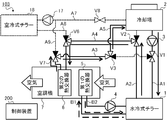
- FIG. 15 shows the flow path of the cooling water in the “normal cooling” operation mode.
- the flow path switching unit 240 transmits an instruction to the first valve V1 and the second valve V2, and switches the valve on the third cooling water channel A3 side in the first valve V1. Close the valve on the fourth cooling water channel A4 side in the second valve V2.
- the flow path switching unit 240 is configured such that the cooling water flowing through the first cooling water path A1 is not supplied to the third cooling water path A3 through the cooling water flow path. Are switched to a flow path that is supplied to the water-cooled chiller 1. Thereby, the cooling water circulates between the cooling tower 2 and the water-cooled chiller 1.
- the cold water cooled by the cooling water in the water-cooled chiller 1 is circulated between the water-cooled chiller 1 and the first heat exchanger 5 by the cold water pump 4.
- the first heat exchanger 5 exchanges heat between cold water and air, thereby reducing the temperature and humidity of the air, and supplying low-temperature and low-humidity air to the conditioned space. Thereby, the air-conditioned space is cooled.
- the air conditioning system 103 cools the air-conditioned space by heat exchange in the first heat exchanger 5.
- the cooling water channels A3 to A5, A7 to A9, the second heat exchanger 6, the cooling water pump 17, and the air cooling chiller 18 are not used.
- FIG. 16 shows a flow path of the cooling water in the operation mode of “first reheat dehumidification” executed in summer when the outside air temperature and the temperature of the cooling water are relatively high.
- the flow path switching unit 240 sends instructions to each of the three valves V1 to V3 to open all the valves in the first valve V1 and the second valve V2, And the valve by the side of the 5th cooling water channel A5 in the 3rd valve V3 is closed.
- the flow path switching unit 240 supplies a part of the cooling water flowing through the first cooling water path A1 to the second heat exchanger 6 via the third cooling water path A3.
- a part other than the part (that is, the remaining part) of the cooling water flowing through the first cooling water channel A1 is switched to the flow path supplied to the water-cooled chiller 1.
- the cooling water circulates between the cooling tower 2 and the water-cooled chiller 1 and between the cooling tower 2 and the second heat exchanger 6.
- the cold water cooled by the cooling water in the water-cooled chiller 1 is circulated between the water-cooled chiller 1 and the first heat exchanger 5 by the cold water pump 4.
- the first heat exchanger 5 reduces the temperature and humidity of the air by exchanging heat between the cold water generated by the water-cooled chiller 1 and the air.
- the second heat exchanger 6 exchanges heat between a part of the cooling water supplied from the cooling tower 2 and the air heat-exchanged with the cold water in the first heat exchanger 5, so that the air Reheat. Changes in the temperature and humidity of the air at this time are the same as in FIG.
- the air conditioning system 103 regenerates the conditioned space by the two-stage heat exchange between the first heat exchanger 5 and the second heat exchanger 6. Heat dehumidify.
- the cooling water channels A5, A7 to A9, the cooling water pump 17 and the air cooling chiller 18 are not used.
- FIG. 17 shows a flow path of the cooling water in the operation mode of “second reheat dehumidification” executed in the intermediate period or winter period when the outside air temperature and the cooling water temperature are relatively low.
- the flow path switching unit 240 transmits an instruction to each of the three valves V1 to V3 to close the valve on the third cooling water channel A3 side in the first valve V1,
- the valve on the cooling tower 2 side in the second valve V2 is closed, and the valve on the first valve V1 side in the third valve V3 is closed.
- the flow path switching unit 240 supplies all of the cooling water flowing through the first cooling water channel A1 to the water-cooled chiller 1, and the cooling water cooled by the water-cooled chiller 1 becomes the second cooling water channel A2.
- the cooling water supplied to the second heat exchanger 6 via the fourth cooling water channel A4 and heat-exchanged with the air in the second heat exchanger 6 is converted into the third cooling water channel A3 and the fifth cooling water channel A4. It switches to the flow path supplied to the cooling tower 2 via cooling water path A5. Accordingly, the cooling water circulates in the order of the cooling tower 2, the water-cooled chiller 1, and the second heat exchanger 6.
- the cold water cooled by the cooling water in the water-cooled chiller 1 is circulated between the water-cooled chiller 1 and the first heat exchanger 5 by the cold water pump 4.
- the first heat exchanger 5 reduces the temperature and humidity of the air by exchanging heat between the cold water generated by the water-cooled chiller 1 and the air.
- the second heat exchanger 6 exchanges heat between a part of the cooling water supplied from the cooling tower 2 and the air heat-exchanged with the cold water in the first heat exchanger 5, so that the air Reheat. Changes in the temperature and humidity of the air at this time are the same as in FIG.
- the air conditioning system 103 regenerates the conditioned space by the two-stage heat exchange between the first heat exchanger 5 and the second heat exchanger 6. Heat dehumidify.
- the cooling water channels A7 to A9, the cooling water pump 17 and the air cooling chiller 18 are not used.
- FIG. 18 shows the flow path of the cooling water in the “free cooling” operation mode that is executed when the temperature of the cooling water is sufficiently low in the winter or intermediate period.
- the flow path switching unit 240 transmits an instruction to each of the three valves V1 to V3, so that the water cooling chiller 1 side of the first valve V1 and the second valve V2 is on the side.
- the valve is closed, and the valve on the fifth cooling water channel A5 side in the third valve V3 is closed.
- the flow path switching unit 240 is configured such that the cooling water flowing through the first cooling water path A1 is not supplied to the water-cooled chiller 1 and all of the cooling water flowing through the first cooling water path A1 It switches to the flow path supplied to the 2nd heat exchanger 6 via 3rd cooling water path A3. Thereby, the cooling water circulates between the cooling tower 2 and the second heat exchanger 6.
- the air conditioning system 103 supplies the cooling water cooled by the outside air in the cooling tower 2 to the second heat exchanger 6 as it is to cool the air-conditioned space.
- the cooling water channels A5, A7 to A9, the water cooling chiller 1, the cooling water pump 4, the first heat exchanger 5, the cooling water pump 17 and the air cooling chiller 18 are not used.
- the “second cooling” is an operation mode in which the cooling capacity is insufficient in “free cooling”, but the cooling water is cooled by the air-cooled chiller 18 when a high cooling capacity is not required compared to “normal cooling”. is there.
- the operation mode of “second cooling” is executed, for example, when the outside air temperature is medium in the intermediate period.
- the air-cooled chiller 18 cools the cooling water cooled by the cooling tower.
- the air conditioning control unit 220 transmits an instruction to switch the flow path of the four-way valve to the air-cooled chiller 18 via the communication unit 204 to cool the cooling water.
- the flow path switching unit 240 supplies the cooling water cooled by the cooling tower 2 to the air-cooled chiller 18 via the seventh cooling water path A7.
- the cooling water cooled by the air-cooled chiller 18 is switched to a flow path that is supplied to the second heat exchanger 6 via the eighth cooling water path A8.
- the flow path switching unit 240 is configured such that the cooling water that has exchanged heat with the air in the second heat exchanger 6 is the third cooling water path A3 and the fifth cooling water path A5. The flow path is switched to the flow path supplied to the cooling tower 2 via the cooling water path A5.
- the fifth condition is a condition under which the air conditioning system 103 starts air conditioning in the “second cooling” operation mode. More specifically, the fifth condition is established when cooling is requested and the outside air temperature is lower than the third threshold value. The case where cooling is requested is when the request acquisition unit 210 acquires a request for starting cooling, or when the timing for starting the cooling determined in the operation schedule has arrived.
- the third threshold is a reference temperature for switching the operation mode from “normal cooling” to “second cooling”, and is set to 15 ° C. or 20 ° C., for example.
- the third threshold value is set to a temperature higher than the above-described second threshold value, which is a reference temperature for switching the operation mode to “free cooling”.
- the air conditioning system 103 performs cooling in the “second cooling” operation mode when the outside air temperature is higher than the second threshold and lower than the third threshold when cooling is requested, and the outside air temperature is When it is smaller than the threshold value of 2 (that is, when the above-described fourth condition is satisfied), the cooling is performed in the “free cooling” operation mode.
- FIG. 19 shows the flow path of the cooling water during the second cooling.
- the flow path switching unit 240 transmits an instruction to each of the six valves V1 to V3 and V6 to V8, so that all of the first valve V1 and the second valve V2 The valve is closed, the valve on the fifth cooling water channel A5 side in the third valve V3 is closed, the valve on the second valve V2 side in the sixth valve V6 is closed, and the ninth cooling water channel in the seventh valve V7 The A9 side valve is closed and the eighth valve V8 is opened.
- the second heat exchanger 6 Since the valve on the ninth cooling water channel A9 side in the seventh valve V7 is closed and the valve on the fifth cooling water channel A5 side in the third valve V3 is closed, the second heat exchanger 6 The output cooling water is supplied to the cooling tower 2 via the third cooling water channel A3 and the fifth cooling water channel A5. Thus, the cooling water circulates through the cooling tower 2, the air-cooled chiller 18 and the second heat exchanger 6 in this order.
- the temperature of the cooling water is lowered by absorbing heat to the outside air in the cooling tower 2, further lowered by being cooled in the air-cooled chiller 18, and in the second heat exchanger 6 It rises by cooling.
- the cooling water whose temperature has risen in the second heat exchanger 6 returns to the cooling tower 2 and is cooled again.
- the second heat exchanger 6 reduces the temperature and humidity of the air by exchanging heat between the cooling water and the air, and supplies low-temperature and low-humidity air to the air-conditioned space. Thereby, the air-conditioned space is cooled. During the second cooling, the water-cooled chiller 1, the cooling water pump 3, the cold water pump 4, and the first heat exchanger 5 are stopped.
- the air-conditioning system 103 saves energy compared to the “normal cooling” operation mode. be able to. Further, since the cooling water is cooled by the air-cooled chiller 18, the cooling can be performed with a higher cooling capacity than the “free cooling” operation mode.
- the air conditioning system 103 can also perform air conditioning in the “heating” operation mode. This will be described below.
- the air-cooled chiller 18 heats the cooling water to generate hot water.
- the air conditioning control unit 220 transmits an instruction to switch the flow path of the four-way valve to the air-cooled chiller 18 via the communication unit 204 to heat the cooling water.
- the flow path switching unit 240 passes through the cooling water flow path through the cooling water (hot water) heated by the air-cooled chiller 18 via the eighth cooling water path A8.
- the cooling water supplied to the heat exchanger 6 and cooled by the second heat exchanger 6 is switched to a flow path that is supplied to the air-cooled chiller 18 via the ninth cooling water path A9.
- the sixth condition is a condition in which the air conditioning system 103 starts air conditioning in the “heating” operation mode. More specifically, the sixth condition is satisfied when the request acquisition unit 210 acquires a request for starting heating, or when the timing for starting heating defined in the operation schedule has arrived.
- FIG. 20 shows the flow path of the cooling water during heating.
- the flow path switching unit 240 transmits an instruction to each of the sixth to eighth valves V6 to V8 and closes the valve on the second valve V2 side in the sixth valve V6.
- the valve on the first valve V1 side in the seventh valve V7 is closed, and the eighth valve V8 is closed. Further, since the first to third valves V1 to V3 are not used, the flow path switching unit 240 closes all these valves.
- the cooling water heated by the air-cooled chiller 18 is supplied to the second heat exchanger 6 by closing the valve on the second valve V2 side in the sixth valve V6.
- the cooling water heat-exchanged with air in the second heat exchanger 6 is air-cooled chiller. 18 is supplied.
- the cooling water circulates between the air-cooled chiller 18 and the second heat exchanger 6.
- the temperature of the cooling water rises by being heated in the air-cooled chiller 18, and the temperature is lowered by exchanging heat with air in the second heat exchanger 6.
- the cooling water whose temperature has decreased in the second heat exchanger 6 returns to the air-cooled chiller 18 and is heated again.
- the second heat exchanger 6 heats the air by exchanging heat between the heated cooling water and the air, and supplies high-temperature air to the air-conditioned space. Thereby, the air-conditioned space is heated.
- the air conditioning system 103 heats the air-conditioned space by circulating the hot water generated by the air-cooled chiller 18. During heating, the water-cooled chiller 1, the cooling tower 2, the cooling water pump 3, the cold water pump 4, and the first heat exchanger 5 are stopped.
- the air conditioning system 103 has a heating operation function in addition to the reheat dehumidification function and the free cooling function, so that it is possible to improve cost effectiveness and user convenience.
- the air conditioning system 101 according to the first embodiment and the air conditioning system 102 according to the second embodiment include “normal cooling”, “first reheat dehumidification”, “second reheat dehumidification”, and “ It was possible to air-condition in four operation modes of “free cooling”.
- the air conditioning system according to the present invention may not have the function of air conditioning in all of these operation modes.
- the air conditioning system may not have the function of “second reheat dehumidification”, may not have the function of “free cooling”, or may not have both functions.
- the air conditioning system may include only the functions of “normal cooling” and “first reheat dehumidification” among these four operation modes, or only the function of “first reheat dehumidification”. May be.
- the control device 200 may not include the temperature acquisition unit 230 that acquires the outside air temperature and the flow path switching unit 240 that switches the flow path of the cooling water.
- the temperature acquisition unit 230 acquires the outside air temperature.
- the temperature acquisition unit 230 may acquire the temperature of the cooling water output from the cooling tower 2.
- the temperature of the cooling water output from the cooling tower 2 is the temperature of the cooling water immediately after being cooled by exchanging heat with the outside air in the cooling tower 2. Since the cooling water is cooled by the outside air in the cooling tower 2, the temperature of the cooling water output from the cooling tower 2 has a large correlation with the outside air temperature.
- the temperature acquisition unit 230 acquires information on the temperature of the cooling water detected by the temperature sensor provided at the cooling water outlet in the cooling tower 2 via the communication unit 204. Then, the flow path switching unit 240 switches the flow path of the cooling water according to the operation mode acquired by the request acquisition unit 210 and the temperature of the cooling water acquired by the temperature acquisition unit 230.
- the eighth cooling water channel A8 from which the cooling water cooled or heated by the air-cooled chiller 18 is output is connected to the fourth cooling water channel A4, and the second heat exchanger 6
- the ninth cooling water channel A9 that guides the cooling water output from the air-cooled chiller 18 was connected to the third cooling water channel A3.
- the eighth cooling water channel A8 may be connected to the third cooling water channel A3, and the ninth cooling water channel A9 may be connected to the fourth cooling water channel A4.
- the cooling water cooled or heated by the air-cooled chiller 18 is supplied to the second heat exchanger 6 via the eighth cooling water channel A8 and the third cooling water channel A3.
- the cooling water output from the second heat exchanger 6 is transferred to the seventh cooling water passage A7 via the fourth cooling water passage A4 and the ninth cooling water passage A9 in the “heating” operation mode. It flows in and is supplied to the air-cooled chiller 18.
- the cooling water output from the second heat exchanger 6 passes to the cooling tower 2 via the fourth cooling water channel A4 and the second cooling water channel A2.
- the flow path switching unit 240 transmits instructions to the second valve V2, the sixth valve V6, and the seventh valve V7 to switch the flow path of the cooling water to such a flow path.
- control device 200 is installed outside the water-cooled chiller 1, the cooling tower 2, and the air conditioner 7, and has been described as an independent device.
- any of the control boards provided in the water-cooled chiller 1, the cooling tower 2, and the air conditioner 7 may function as the control device 200 described above.
- the control device described above is obtained by cooperation of a plurality of devices among the control board provided in the water-cooled chiller 1, the cooling tower 2 and the air conditioner 7 and the devices installed outside these. 200 may function.
- control unit 201 of the control device 200 the CPU executes a program stored in the ROM or the storage unit 202, whereby the request acquisition unit 210, the air conditioning control unit 220, the temperature acquisition unit 230, and the flow path. It functioned as each of the switching unit 240.
- the control unit 201 may be dedicated hardware.
- the dedicated hardware is, for example, a single circuit, a composite circuit, a programmed processor, an ASIC (Application Specific Integrated ⁇ Circuit), an FPGA (Field-Programmable Gate Array), or a combination thereof.
- ASIC Application Specific Integrated ⁇ Circuit
- FPGA Field-Programmable Gate Array
- each unit may be realized by dedicated hardware, and the other part may be realized by software or firmware.
- the control unit 201 can realize the above-described functions by hardware, software, firmware, or a combination thereof.
- the computer can also function as the control device 200 according to the present invention. is there.
- a program distribution method is arbitrary.
- a computer-readable record such as a CD-ROM (Compact Disk ROM), a DVD (Digital Versatile Disk), an MO (Magneto Optical Disk), or a memory card. It may be distributed by being stored in a medium or distributed via a communication network such as the Internet.
- the present invention can be suitably employed in an air conditioning system or the like.
Landscapes
- Engineering & Computer Science (AREA)
- Combustion & Propulsion (AREA)
- Mechanical Engineering (AREA)
- General Engineering & Computer Science (AREA)
- Chemical & Material Sciences (AREA)
- Life Sciences & Earth Sciences (AREA)
- Signal Processing (AREA)
- Sustainable Development (AREA)
- Sustainable Energy (AREA)
- Physics & Mathematics (AREA)
- Fuzzy Systems (AREA)
- Mathematical Physics (AREA)
- Other Air-Conditioning Systems (AREA)
- Air Conditioning Control Device (AREA)
- Central Air Conditioning (AREA)
Abstract
空調システム(101)において、冷却塔(2)は、冷却水を冷却する。熱源機は、冷却塔(2)で冷却された冷却水によって冷水を生成する。冷却水循環路(A)は、冷却塔(2)と熱源機との間で冷却水を循環させる。第1の熱交換器(5)は、熱源機で生成された冷水と、空気と、の間で熱交換する。冷水循環路(B)は、熱源機と第1の熱交換器(5)との間で冷水を循環させる。第2の熱交換器(6)は、冷却塔(2)で冷却された冷却水の一部と、第1の熱交換器(5)で冷水と熱交換された空気と、の間で熱交換する。冷却水分岐路(A')は、冷却水循環路(A)において冷却塔(2)から熱源機に導かれる冷却水の一部を第2の熱交換器(6)に導き、第2の熱交換器(6)で空気と熱交換された冷却水の一部を冷却水循環路(A)に導く。
Description
本発明は、空調システムに関する。
冷却水によって冷水を冷却し、冷水と空気との間で熱交換することによって空調する技術が知られている。
例えば、特許文献1は、熱源機で生成した冷水を空調機に供給する冷水回路と、冷水回路で回収した排熱を冷却塔により大気に放出する冷却水回路と、を備えた空調システムを開示している。特許文献1に開示された空調システムは、冷却水の温度が閾値以下となったときに、熱源機をバイパスして冷却水を直接空調機に供給することで、フリークーリングを実施する。これにより、外気温度の低下時に省エネが可能となる。
特許文献1に開示された空調システムは、外気温度が低くなる期間にはフリークーリングを実施できるが、外気温度が高くなる期間にはフリークーリングを実施できない。そのため、フリークーリングを実施できる期間が限られている。このような状況に鑑み、冷却水をより有効に利用して空調することが求められている。
本発明は、上述のような課題を解決するためになされたものであり、冷却水と冷水とを用いた空調において、冷却水を有効に利用することが可能な空調システム等を提供することを目的とする。
冷却水を冷却する冷却塔と、
前記冷却塔で冷却された前記冷却水によって冷水を生成する熱源機と、
前記冷却塔と前記熱源機との間で前記冷却水を循環させる冷却水循環路と、
前記熱源機で生成された前記冷水と、空気と、の間で熱交換する第1の熱交換器と、
前記熱源機と前記第1の熱交換器との間で前記冷水を循環させる冷水循環路と、
前記冷却塔で冷却された前記冷却水の一部と、前記第1の熱交換器で前記冷水と熱交換された前記空気と、の間で熱交換する第2の熱交換器と、
前記冷却水循環路において前記冷却塔から前記熱源機に導かれる前記冷却水の前記一部を前記第2の熱交換器に導き、前記第2の熱交換器で前記空気と熱交換された前記冷却水の前記一部を前記冷却水循環路に導く冷却水分岐路と、を備える。
本発明では、冷却塔で冷却された冷却水を冷却塔と熱源機との間で循環させ、熱源機で生成した冷水を熱源機と第1の熱交換器との間で循環させ、第1の熱交換器において、熱源機で生成された冷水と空気との間で熱交換し、冷却塔から熱源機に導かれる冷却水の一部を第2の熱交換器に導き、第2の熱交換器において、冷却塔で冷却された冷却水の一部と第1の熱交換器で冷水と熱交換された空気との間で熱交換する。従って、本発明によれば、冷却水と冷水とを用いた空調において、冷却水を有効に利用することができる。
以下、本発明の実施の形態について、図面を参照しながら詳細に説明する。なお、図中同一又は相当部分には同一符号を付す。なお、実施の形態2,3以降において特に記述されない事項については、実施の形態1と同様である。
(実施の形態1)
図1に、本発明の実施の形態1における空調システム101の概略を示す。空調システム101は、冷却塔2で冷却された冷却水を利用して、空調対象の空間(以下、「空調空間」という。)を空調するシステムである。空調とは、空調空間の空気の温度、湿度、清浄度又は気流等を調整することであって、具体的には、暖房、冷房、除湿、加湿及び空気清浄等を含む。空調空間とは、例えば一般的な家屋、集合住宅、オフィスビル、施設又は工場等の内部の空間である。
図1に、本発明の実施の形態1における空調システム101の概略を示す。空調システム101は、冷却塔2で冷却された冷却水を利用して、空調対象の空間(以下、「空調空間」という。)を空調するシステムである。空調とは、空調空間の空気の温度、湿度、清浄度又は気流等を調整することであって、具体的には、暖房、冷房、除湿、加湿及び空気清浄等を含む。空調空間とは、例えば一般的な家屋、集合住宅、オフィスビル、施設又は工場等の内部の空間である。
図1に示すように、空調システム101は、冷水を生成する水冷式チラー1と、冷却水を外気で冷却する冷却塔2と、冷却水を循環させる冷却水ポンプ3と、冷水を循環させる冷水ポンプ4と、空気と冷水との間で熱交換する第1の熱交換器5と、空気と冷却水との間で熱交換する第2の熱交換器6と、第1の熱交換器5及び第2の熱交換器6を含む空調機7と、冷却水の流路を切り替える3つの弁(第1の弁V1、第2の弁V2及び第3の弁V3)と、システム全体を制御する制御装置200と、を備える。
また、空調システム101は、各構成の間における冷却水又は冷水の流路として、冷却水を循環させる冷却水循環路Aと、冷却水循環路Aから分岐した冷却水分岐路A’と、冷水を循環させる冷水循環路Bと、を備える。空調システム101は、冷却水を一次冷媒として用い、且つ、冷水を二次冷媒として用いた、いわゆる二次冷媒循環型又は間接冷却方式のシステムである。
<水冷式チラー1>
水冷式チラー1は、冷水を生成する装置である。冷水とは、空調空間の空気を冷却するための媒体である。水冷式チラー1は、冷却水と冷水との間で熱交換し、冷却水を冷熱源として冷水を冷却する熱源機として機能する。水冷式チラー1は、例えばCO2(二酸化炭素)又はHFC(ハイドロフルオロカーボン)等を冷媒として用いたヒートポンプ方式のチラーである。水冷式チラー1は、例えば空調空間の外側であって、空調空間と同じ敷地内に設置される。
水冷式チラー1は、冷水を生成する装置である。冷水とは、空調空間の空気を冷却するための媒体である。水冷式チラー1は、冷却水と冷水との間で熱交換し、冷却水を冷熱源として冷水を冷却する熱源機として機能する。水冷式チラー1は、例えばCO2(二酸化炭素)又はHFC(ハイドロフルオロカーボン)等を冷媒として用いたヒートポンプ方式のチラーである。水冷式チラー1は、例えば空調空間の外側であって、空調空間と同じ敷地内に設置される。
図2に示すように、水冷式チラー1は、圧縮機21と、第1の冷媒-水熱交換器22と、膨張装置23と、第2の冷媒-水熱交換器24と、これらを環状に接続している冷媒回路25と、制御基板26と、を備える。冷媒回路25は、冷媒が循環する回路であって、ヒートポンプ又は冷凍サイクル等とも呼ばれる。
圧縮機21は、冷媒回路25を流れる冷媒を圧縮し、冷媒の温度及び圧力を上昇させる。圧縮機21は、運転周波数(回転数)に応じて容量(単位当たりの送り出し量)を変化させることができるインバータ回路を備える。圧縮機21は、制御基板26から指示される制御値に従って運転周波数を変更する。圧縮機21に吸入された冷媒は、高温且つ高圧のガス冷媒に圧縮されて吐出される。
第1の冷媒-水熱交換器22は、冷媒回路25を流れる冷媒と、冷却塔2から供給される冷却水と、の間で熱交換する。第1の冷媒-水熱交換器22は、例えばプレート式又は二重管式等の熱交換器である。圧縮機21で圧縮された高温且つ高圧の冷媒は、第1の冷媒-水熱交換器22で冷却水と熱交換することで凝縮し、高圧の液体に変化する。第1の冷媒-水熱交換器22で冷媒が凝縮する際、冷却水は熱を与えられるのでその温度は上昇する。
膨張装置23は、冷媒回路25を流れる冷媒を膨張させて、冷媒の温度及び圧力を下降させる。膨張装置23は、制御基板26から指示される制御値に従って弁の開度を変更し、冷媒の減圧量を調整する。第1の冷媒-水熱交換器22で高圧の液体に変化した冷媒は、膨張装置23で低温且つ低圧の二相冷媒に減圧される。
第2の冷媒-水熱交換器24は、冷媒回路25を流れる冷媒と、空調機7から供給される冷水と、の間で熱交換する。第2の冷媒-水熱交換器24は、例えばプレート式又は二重管式等の熱交換器である。膨張装置23で減圧された冷媒は、第2の冷媒-水熱交換器24で冷水と熱交換することで蒸発し、低圧の気体に変化する。低圧の気体に変化した冷媒は、圧縮機21に戻って再び高温且つ高圧の気体に圧縮される。第2の冷媒-水熱交換器24で冷媒が蒸発する際、冷水は熱を奪われるのでその温度は低下する。
制御基板26は、いずれも図示しないが、CPU、ROM、RAM、通信インタフェース及び読み書き可能な不揮発性の半導体メモリ等を備える。制御基板26は、圧縮機21及び膨張装置23と、図示しない通信線を介して通信可能に接続している。また、制御基板26は、図示しない通信線を介して、制御装置200と通信可能に接続している。制御基板26は、制御装置200から送信された指示に従って、圧縮機21及び膨張装置23の動作を制御する。
<冷却塔2>
冷却塔2は、冷却水を冷却する設備である。冷却水とは、水冷式チラー1で冷水を冷却するための媒体である。冷却塔2は、外気を送風する送風機を備えており、冷却水を外気と熱交換させることで、冷却水を冷却する。具体的に説明すると、冷却塔2は、冷却水を外気と直接的に接触させて蒸発させる方式(開放式)、又は、外気と接触した熱媒体を循環させることで冷却水を外気と間接的に接触させて蒸発させる方式(密閉式)で、冷却水を冷却する。このように、冷却塔2は、外気を冷却水に直接的又は間接的に接触させることで、冷却水を冷却する。冷却塔2は、例えば空調空間の外側であって、空調空間と同じ敷地内に設置される。
冷却塔2は、冷却水を冷却する設備である。冷却水とは、水冷式チラー1で冷水を冷却するための媒体である。冷却塔2は、外気を送風する送風機を備えており、冷却水を外気と熱交換させることで、冷却水を冷却する。具体的に説明すると、冷却塔2は、冷却水を外気と直接的に接触させて蒸発させる方式(開放式)、又は、外気と接触した熱媒体を循環させることで冷却水を外気と間接的に接触させて蒸発させる方式(密閉式)で、冷却水を冷却する。このように、冷却塔2は、外気を冷却水に直接的又は間接的に接触させることで、冷却水を冷却する。冷却塔2は、例えば空調空間の外側であって、空調空間と同じ敷地内に設置される。
冷却塔2は、いずれも図示しないが、CPU、ROM、RAM、通信インタフェース及び読み書き可能な不揮発性の半導体メモリ等を含む制御基板を備える。制御基板は、図示しない通信線を介して、制御装置200と通信可能に接続している。制御基板は、制御装置200から送信された指示に従って、冷却塔2の動作を制御する。
<空調機7>
空調機7は、空調空間を空調する設備である。空調機7は、AHU(エアハンドリングユニット)とも呼ばれる。空調機7は、空調空間に空調された空気を供給可能な場所に設置される。空調機7は、例えば、空調空間の壁の上部又は天井に設置される。或いは、空調機7は、それぞれが空調空間である複数の部屋にダクトで接続された専用の機械室に設置されても良い。
空調機7は、空調空間を空調する設備である。空調機7は、AHU(エアハンドリングユニット)とも呼ばれる。空調機7は、空調空間に空調された空気を供給可能な場所に設置される。空調機7は、例えば、空調空間の壁の上部又は天井に設置される。或いは、空調機7は、それぞれが空調空間である複数の部屋にダクトで接続された専用の機械室に設置されても良い。
図3に示すように、空調機7は、空気と冷水との間で熱交換する第1の熱交換器5と、空気と冷却水との間で熱交換する第2の熱交換器6と、空気を送風する空気送風装置31と、を備える。第1の熱交換器5及び第2の熱交換器6は、いずれも空気と水との間で熱交換する、周知の方式の熱交換器である。第1の熱交換器5は、水冷式チラー1で生成された冷水と、空気と、の間で熱交換する。第2の熱交換器6は、第1の熱交換器5の下流側に設置されており、冷却塔2で冷却された冷却水の一部と、第1の熱交換器5で冷水と熱交換された空気と、の間で熱交換する。
空気送風装置31によって空調機7に吸い込まれた空気は、まず第1の熱交換器5を通過し、冷水と熱交換される。第1の熱交換器5で冷水と熱交換された空気は、更に第2の熱交換器6を通過し、冷却水と熱交換される。このように、空調機7に吸い込まれた空気は、2回に亘って熱交換された後、空調空間へ供給される。
空調機7は、いずれも図示しないが、CPU、ROM、RAM、通信インタフェース及び読み書き可能な不揮発性の半導体メモリ等を含む制御基板を備える。制御基板は、図示しない通信線を介して、制御装置200と通信可能に接続している。制御基板は、制御装置200から送信された指示に従って、空調機7の動作を制御する。
<冷却水循環路A、冷却水分岐路A’及び冷水循環路B>
冷却水循環路Aは、冷却塔2と水冷式チラー1との間に設けられており、冷却塔2と水冷式チラー1との間で冷却水を循環させる。冷却水循環路Aは、それぞれ冷却塔2と水冷式チラー1とに接続された第1の冷却水路A1と第2の冷却水路A2とを備える。第1の冷却水路A1は、冷却塔2で冷却された冷却水を水冷式チラー1に導く、冷却水の供給路(往水路)である。第2の冷却水路A2は、水冷式チラー1で冷水を冷却した冷却水を冷却塔2に導く、冷却水の還流路(還水路)である。
冷却水循環路Aは、冷却塔2と水冷式チラー1との間に設けられており、冷却塔2と水冷式チラー1との間で冷却水を循環させる。冷却水循環路Aは、それぞれ冷却塔2と水冷式チラー1とに接続された第1の冷却水路A1と第2の冷却水路A2とを備える。第1の冷却水路A1は、冷却塔2で冷却された冷却水を水冷式チラー1に導く、冷却水の供給路(往水路)である。第2の冷却水路A2は、水冷式チラー1で冷水を冷却した冷却水を冷却塔2に導く、冷却水の還流路(還水路)である。
冷却水分岐路A’は、冷却水循環路Aと第2の熱交換器6との間に設けられており、冷却水循環路Aを流れる冷却水の一部を分岐させて第2の熱交換器6に供給する分岐路である。冷却水分岐路A’は、冷却水循環路Aにおいて冷却塔2から水冷式チラー1に導かれる冷却水の一部を第2の熱交換器6に導き、第2の熱交換器6で空気と熱交換された冷却水の一部を冷却水循環路Aに導く。
冷却水分岐路A’は、第1の冷却水路A1の途中と第2の熱交換器6とに接続された第3の冷却水路A3と、第2の冷却水路A2の途中と第2の熱交換器6とに接続された第4の冷却水路A4と、を備える。第3の冷却水路A3は、第1の冷却水路A1を流れる冷却水の一部を第2の熱交換器6に導く。第4の冷却水路A4は、第2の熱交換器6で空気と熱交換した冷却水を第2の冷却水路A2に導く。
また、冷却水分岐路A’は、第3の冷却水路A3の途中と冷却塔2とに接続された第5の冷却水路A5を備える。第5の冷却水路A5は、第3の冷却水路A3を流れる冷却水を、冷却水循環路Aを経由せずに冷却塔2に導くバイパス路である。
冷却水循環路Aには、冷却水ポンプ3が設けられている。冷却水ポンプ3は、冷却塔2によって生成された冷却水を送り出し、冷却水循環路A及び冷却水分岐路A’を循環させる。冷却水ポンプ3は、インバータ回路を備えており、制御装置200から指示される制御値に従って駆動回転数を調整することで、送り出す冷却水の量を変化させる。冷却水ポンプ3によって冷却塔2から送り出された冷却水は、水冷式チラー1と第1の熱交換器5とのいずれか一方又は両方を通って水冷式チラー1に戻る。
冷却水循環路Aには、第1の弁V1、第2の弁V2及び第3の弁V3が設けられている。第1の弁V1、第2の弁V2及び第3の弁V3のそれぞれは、電磁式又は電動式等の周知の方式で弁を開閉する電動式の三方弁である。第1の弁V1、第2の弁V2及び第3の弁V3のそれぞれは、制御装置200からの制御指令に従って弁の開閉を切り替えることで、冷却水の流路を変更する。
第1の弁V1は、冷却塔2から第1の冷却水路A1に出力された冷却水を、水冷式チラー1に流すか、第2の熱交換器6に流すか、又は、水冷式チラー1と第2の熱交換器6との両方に流すかを切り替える。第2の弁V2は、水冷式チラー1から第2の冷却水路A2に出力された冷却水と、第2の熱交換器6から第4の冷却水路A4に出力された冷却水と、のうちのいずれか一方のみを冷却塔2に導くか、又は、その両方を冷却塔2へ導くかを切り替える。第3の弁V3は、第3の冷却水路A3を流れる冷却水を、第5の冷却水路A5に導くか否かを切り替える。
冷水循環路Bは、水冷式チラー1と第1の熱交換器5との間に設けられており、水冷式チラー1と第1の熱交換器5との間で冷水を循環させる。冷水循環路Bは、それぞれ水冷式チラー1と第1の熱交換器5とに接続された、第1の冷水路B1と第2の冷水路B2とを備える。第1の冷水路B1は、水冷式チラー1で生成された冷水を第1の熱交換器5に導く、冷水の供給路(往水路)である。第2の冷水路B2は、第1の熱交換器5で空気と熱交換された冷水を水冷式チラー1に導く、冷水の還流路(還水路)である。
冷水循環路Bには、冷水ポンプ4が設けられている。冷水ポンプ4は、水冷式チラー1によって生成された冷水を送り出し、冷水循環路Bを循環させる。冷水ポンプ4は、インバータ回路を備えており、制御装置200から指示される制御値に従って駆動回転数を調整することで、送り出す冷水の量を変化させる。冷水ポンプ4によって水冷式チラー1から送り出された冷水は、第1の熱交換器5を通って水冷式チラー1に戻る。
<制御装置200>
制御装置200は、空調システム101の全体を統括的に制御する。制御装置200は、例えば空調空間の内側、又は、空調空間と同じ敷地内の適宜の場所に設置される。
制御装置200は、空調システム101の全体を統括的に制御する。制御装置200は、例えば空調空間の内側、又は、空調空間と同じ敷地内の適宜の場所に設置される。
図4に、制御装置200のハードウェア構成を示す。図4に示すように、制御装置200は、制御部201と、記憶部202と、計時部203と、通信部204と、ユーザインタフェース205と、を備える。これら各部はバス209を介して接続されている。
制御部201は、いずれも図示しないが、CPU、ROM及びRAM等を備える。CPUは、中央処理装置、中央演算装置、プロセッサ、マイクロプロセッサ、マイクロコンピュータ又はDSP(Digital Signal Processor)等ともいう。制御部201において、CPUは、ROMに格納されたプログラム及びデータを読み出し、RAMをワークエリアとして用いて、制御装置200を統括制御する。
記憶部202は、例えば、フラッシュメモリ、EPROM(Erasable Programmable ROM)又はEEPROM(Electrically Erasable Programmable ROM)等の不揮発性の半導体メモリであって、いわゆる二次記憶装置(補助記憶装置)としての役割を担う。記憶部202は、制御部201が各種処理を行うために使用する各種プログラム及びデータ、並びに、制御部201が各種処理を行うことにより生成又は取得する各種データを記憶する。
計時部203は、RTC(Real Time Clock)を備えており、制御装置200の電源がオフの間も計時を継続する計時デバイスである。
通信部204は、外部の機器と通信するためのインタフェースである。通信部204は、水冷式チラー1、冷却塔2、冷却水ポンプ3、冷水ポンプ4、空調機7、第1の弁V1、第2の弁V2及び第3の弁V3のそれぞれと、有線又は無線で通信可能に接続されており、これら各構成要素と周知の通信規格に則って通信する。また、通信部204は、ローカルエリアネットワーク及び広域ネットワークに接続されており、空調システム101の外部の機器と通信する。
ユーザインタフェース205は、表示部206と入力部207とを備える。表示部206は、LCD(Liquid Crystal Display)パネル、有機EL又はLED(Light Emitting Diode)等の表示デバイスである。入力部207は、タッチパネル、タッチパッド、スイッチ又は各種の押圧ボタン等の入力デバイスである。ユーザインタフェース205は、入力部207を介してユーザから各種の操作を受け付け、また、表示部206を介して各種の表示画像を表示する。なお、表示部206と入力部207とは、これらが互いに重畳して配置されたタッチパネル(タッチスクリーン)として構成されるものであってもよい。
制御装置200は、ユーザインタフェース205(表示部206及び入力部207)を装置本体に備えていても良いし、ユーザインタフェース205を装置本体に備えず、装置本体から分離されたリモコンがユーザインタフェース205として機能していても良い。リモコンがユーザインタフェース205として機能する場合、制御装置200は、通信部204を介してリモコンと通信する。通信部204は、リモコンの表示部206での表示画像を示す信号を送信し、リモコンの入力部207によってユーザから受け付けた操作内容を示す信号を受信する。
次に、図5を参照して、制御部201の機能的な構成について説明する。図5に示すように、制御部201は、機能的に、要求取得部210と、空調制御部220と、温度取得部230と、流路切替部240と、を備える。これらの各機能は、ソフトウェア、ファームウェア、又は、ソフトウェアとファームウェアとの組み合わせによって実現される。ソフトウェア及びファームウェアは、プログラムとして記述され、ROM又は記憶部202に格納される。そして、CPUが、ROM又は記憶部202に記憶されたプログラムを実行することによって、各機能を実現する。
要求取得部210は、空調システム101に対する運転の要求を取得する。例えば、ユーザは、入力部207を操作して、又は通信部204を介して外部から、空調の開始、空調の終了、設定温度の変更、又は運転モードの変更等の要求を入力することができる。要求取得部210は、このようにしてユーザから入力された要求を取得する。或いは、要求取得部210は、予め定められた運転スケジュールに従って発せられる運転の要求を、通信部204を介して取得する。要求取得部210は、制御部201が通信部204又は入力部207等と協働することによって実現する。
空調システム101は、詳細には後述するように、「冷房」又は「再熱除湿」の運転モードで空調することができる。より詳細には、「冷房」の運転モードとして、「通常冷房」と「フリークーリング」とがあり、「再熱除湿」の運転モードとして、「第1の再熱除湿」と「第2の再熱除湿」とがある。ユーザは、「冷房」又は「再熱除湿」の運転モードのうちから所望の運転モードを選択することができる。要求取得部210は、このようにして選択された運転モードを取得する。
空調制御部220は、空調システム101における空調動作を制御する。具体的に説明すると、空調制御部220は、通信部204を介して水冷式チラー1、冷却塔2、冷却水ポンプ3、冷水ポンプ4及び空調機7のそれぞれと通信し、各機器に動作の指示を送信する。空調制御部220は、制御部201が通信部204と協働することによって実現する。
例えば、要求取得部210が空調開始の要求を取得した場合、空調制御部220は、水冷式チラー1の動作開始の指示を制御基板26に送信し、圧縮機21及び膨張装置23を駆動させて、水冷式チラー1に冷水を生成させる。これと共に、空調制御部220は、冷却水ポンプ3及び冷水ポンプ4を駆動させて、冷却水及び冷水を循環させる。更に、空調制御部220は、冷却塔2及び空調機7に動作開始の指示を送信し、冷却塔2に冷却水を冷却させ、空調機7に空調を開始させる。
温度取得部230は、外気温度を取得する。外気温度とは、空調空間の外部であって、屋外の空気の温度をいう。外気温度は、図示しないが、屋外に設けられたサーミスタ又は熱電対等の温度センサによって検知される。温度取得部230は、温度センサによって検知された外気温度の情報を、通信部204を介して取得する。温度取得部230は、制御部201が通信部204と協働することによって実現する。
流路切替部240は、冷却水循環路A及び冷却水分岐路A’における冷却水の流路を切り替える。冷却水の流路とは、冷却水循環路A及び冷却水分岐路A’において冷却水が循環する経路である。流路切替部240は、通信部204を介して第1の弁V1、第2の弁V2及び第3の弁V3のそれぞれに弁の開閉を切り替える指示を送信することで、各三方弁における冷却水が流れる方向を切り替える。これにより、流路切替部240は、冷却水の流路を変更する。流路切替部240は、制御部201が通信部204と協働することによって実現する。
より詳細に説明すると、流路切替部240は、要求取得部210によって取得された運転モードと、温度取得部230によって取得された外気温度と、に応じて、冷却水の流路を切り替える。以下、空調システム101が「通常冷房」、「第1の再熱除湿」、「第2の再熱除湿」及び「フリークーリング」の各運転モードで運転する場合について説明する。
<通常冷房>
第1に、「通常冷房」の運転モードについて説明する。通常冷房とは、水冷式チラー1で生成された冷水によって空気を冷却することで空調空間を冷房する運転モードである。
第1に、「通常冷房」の運転モードについて説明する。通常冷房とは、水冷式チラー1で生成された冷水によって空気を冷却することで空調空間を冷房する運転モードである。
流路切替部240は、第1の条件が成立した場合、冷却水の流路を、第1の冷却水路A1を流れる冷却水の全てが水冷式チラー1に供給される流路に切り替える。第1の条件とは、空調システム101が「通常冷房」の運転モードで空調を開始する条件である。具体的に説明すると、第1の条件は、要求取得部210が冷房の開始の要求を取得した場合、又は、運転スケジュールに定められた冷房を開始するタイミングが到来した場合に、成立する。
図6に、通常冷房時における冷却水の流路を示す。第1の条件が成立した場合、流路切替部240は、第1の弁V1と第2の弁V2とに指示を送信し、第1の弁V1における第3の冷却水路A3側の弁を閉じ、第2の弁V2における第4の冷却水路A4側の弁を閉じる。第1の弁V1における第3の冷却水路A3側の弁を閉じることで、冷却塔2で冷却された冷却水は、冷却水分岐路A’及び第2の熱交換器6には供給されず、その全てが水冷式チラー1に供給される。また、第2の弁V2における第4の冷却水路A4側の弁を閉じることで、水冷式チラー1で冷水を冷却した後の冷却水は、冷却水分岐路A’及び第2の熱交換器6には供給されず、その全てが冷却塔2に供給される。このように、冷却水は、冷却塔2と水冷式チラー1との間で循環する。このような流路において、冷却水の温度は、冷却塔2では外気に吸熱されることで低下し、水冷式チラー1では冷水を冷却することで上昇する。
水冷式チラー1で冷却水によって冷却された冷水は、冷水ポンプ4によって水冷式チラー1と第1の熱交換器5の間を循環する。このとき、冷水の温度は、水冷式チラー1で冷却水と熱交換することによって低下し、第1の熱交換器5で空気と熱交換することにより上昇する。
第1の熱交換器5は、冷水と空気との間で熱交換することで、空気の温度と湿度とを低下させ、低温低湿度の空気を空調空間に供給する。これにより、空調空間が冷房される。なお、第2の熱交換器6は、冷却水分岐路A’に冷却水が流れていないため、使用されない。このように、「通常冷房」の運転モードでは、空調システム101は、第1の熱交換器5での熱交換によって、空調空間を冷房する。
なお、図6では、三方弁において弁が閉じられた方向を黒く塗り潰して示している。また、冷却水循環路A及び冷却水分岐路A’において冷却水が流れる流路を実線で示し、冷却水が流れない流路を点線で示している。以降の図においても同様である。
<第1の再熱除湿>
第2に、「第1の再熱除湿」の運転モードについて説明する。再熱除湿とは、冷水によって空気を冷却してその湿度を低下させた後、冷却水によって空気を再熱して空調空間に供給する運転モードである。空調システム101は、再熱除湿として、「第1の再熱除湿」及び「第2の再熱除湿」の2つの運転モードで運転できる。「第1の再熱除湿」は、外気温度及び冷却水の温度が相対的に高い夏期に実行される運転モードであり、「第2の再熱除湿」は、外気温度及び冷却水の温度が相対的に低い中間期又は冬期に実行される運転モードである。
第2に、「第1の再熱除湿」の運転モードについて説明する。再熱除湿とは、冷水によって空気を冷却してその湿度を低下させた後、冷却水によって空気を再熱して空調空間に供給する運転モードである。空調システム101は、再熱除湿として、「第1の再熱除湿」及び「第2の再熱除湿」の2つの運転モードで運転できる。「第1の再熱除湿」は、外気温度及び冷却水の温度が相対的に高い夏期に実行される運転モードであり、「第2の再熱除湿」は、外気温度及び冷却水の温度が相対的に低い中間期又は冬期に実行される運転モードである。
流路切替部240は、第2の条件が成立した場合、冷却水の流路を、第1の冷却水路A1を流れる冷却水の一部が第3の冷却水路A3を経由して第2の熱交換器6に供給され、第1の冷却水路A1を流れる冷却水の当該一部以外の部分(すなわち残りの部分)が水冷式チラー1に供給される流路に切り替える。第2の条件とは、空調システム101が「第1の再熱除湿」の運転モードで空調を開始する条件である。具体的に説明すると、第2の条件は、再熱除湿が要求された場合であって、且つ、温度取得部230によって取得された外気温度が第1の閾値より大きい場合に、成立する。
再熱除湿が要求された場合とは、要求取得部210が再熱除湿の開始の要求を取得した場合、又は、運転スケジュールに定められた再熱除湿を開始するタイミングが到来した場合である。第1の閾値は、「第1の再熱除湿」と「第2の再熱除湿」とを切り替える基準となる温度であって、例えば25℃又は30℃等に予め設定される。
図7に、第1の再熱除湿時における冷却水の流路を示す。第2の条件が成立した場合、流路切替部240は、3つの弁V1~V3のそれぞれに指示を送信することで、第1の弁V1及び第2の弁V2における全ての弁を開き、且つ、第3の弁V3における第5の冷却水路A5側の弁を閉じる。第1の弁V1における全ての弁を開くことで、冷却塔2で冷却された冷却水は、水冷式チラー1と第2の熱交換器6との両方に分割されて供給される。言い換えると、冷却塔2で冷却された冷却水のうちの、第1の部分が水冷式チラー1に供給され、第1の部分以外の第2の部分が第2の熱交換器6に供給される。また、第2の弁V2における全ての弁を開き、且つ、第3の弁V3における第5の冷却水路A5側の弁を閉じることで、水冷式チラー1で冷水を冷却した後の第1の部分の冷却水と、第2の熱交換器6で空気と熱交換した後の第2の部分の冷却水とは、第2の弁V2で合流し、混合されて水冷式チラー1に戻る。このように、冷却水は、冷却塔2と水冷式チラー1との間、及び、冷却塔2と第2の熱交換器6との間のそれぞれで循環する。
このような流路において、冷却水の温度は、冷却塔2では外気に吸熱されることで低下し、水冷式チラー1では冷水を冷却することで上昇し、第2の熱交換器6では空気を再熱することで温度が低下する。水冷式チラー1で温度が上昇した第1の部分の冷却水は、第2の熱交換器6で温度が低下した第2の部分の冷却水と第2の弁V2で混合することで、冷却塔2に戻る前にある程度その温度が低下する。そのため、冷却塔2で冷却水を冷却する負荷が減少し、消費エネルギーを節約することができる。
水冷式チラー1で冷却水によって冷却された冷水は、冷水ポンプ4によって水冷式チラー1と第1の熱交換器5の間を循環する。このとき、冷水の温度は、水冷式チラー1で冷却水と熱交換することによって低下し、第1の熱交換器5で空気と熱交換することにより上昇する。
第1の熱交換器5は、水冷式チラー1で生成された冷水と、空気と、の間で熱交換することで、空気の温度と湿度とを低下させる。第1の熱交換器5で冷水に冷却されることで、空気の温度は、冷却塔2から供給される冷却水の温度よりも低下する。第2の熱交換器6は、冷却塔2から供給された冷却水の一部と、第1の熱交換器5で冷水と熱交換された空気と、の間で熱交換することで、空気を再熱する。
図8に、第1の熱交換器5及び第2の熱交換器6を通過する際における空気の温度及び湿度の変化を、空気線図上に示す。図8に示すように、第1の熱交換器5の入口付近、すなわち空調機7に空気が流入する前においては、空気の温度及び湿度は、どちらも比較的高い。これに対して、第1の熱交換器5の出口付近での空気の温度及び湿度は、第1の熱交換器5で冷水に冷却されることで低下する。その後、第2の熱交換器6で冷却水に再熱されることによって、第2の熱交換器6の出口付近での空気の温度は上昇する。このようにして生成された中温度且つ低湿度の空気が、空調空間に供給される。このように、「第1の再熱除湿」の運転モードでは、空調システム101は、第1の熱交換器5と第2の熱交換器6とによる2段階の熱交換によって、空調空間を再熱除湿する。
<第2の再熱除湿>
第3に、「第2の再熱除湿」の運転モードについて説明する。
第3に、「第2の再熱除湿」の運転モードについて説明する。
流路切替部240は、第3の条件が成立した場合、冷却水の流路を、第1の冷却水路A1を流れる冷却水の全てが水冷式チラー1に供給され、水冷式チラー1で冷水を冷却した冷却水が第2の冷却水路A2と第4の冷却水路A4とを経由して第2の熱交換器6に供給され、且つ、第2の熱交換器6で空気と熱交換した冷却水が第3の冷却水路A3と第5の冷却水路A5とを経由して冷却塔2に供給される流路に切り替える。第3の条件とは、空調システム101が「第2の再熱除湿」の運転モードで空調を開始する条件である。具体的に説明すると、第3の条件は、再熱除湿が要求された場合であって、且つ、温度取得部230によって取得された外気温度が第1の閾値より小さい場合に、成立する。
図9に、第2の再熱除湿時における冷却水の流路を示す。第3の条件が成立した場合、流路切替部240は、3つの弁V1~V3のそれぞれに指示を送信することで、第1の弁V1における第3の冷却水路A3側の弁を閉じ、第2の弁V2における冷却塔2側の弁を閉じ、第3の弁V3における第1の弁V1側の弁を閉じる。第1の弁V1における第3の冷却水路A3側の弁を閉じることで、冷却塔2で冷却された冷却水は、冷却水分岐路A’及び第2の熱交換器6には供給されず、その全てが水冷式チラー1に供給される。また、第2の弁V2における冷却塔2側の弁を閉じることで、水冷式チラー1で冷水を冷却した後の冷却水は、冷却塔2には供給されず、その全てが第4の冷却水路A4を経由して第2の熱交換器6には供給される。更に、第3の弁V3における第1の弁V1側の弁を閉じることで、第2の熱交換器6で空気と熱交換された後の冷却水は、第3の冷却水路A3と第5の冷却水路A5とを経由して冷却塔2に戻る。このように、冷却水は、冷却塔2、水冷式チラー1、及び第2の熱交換器6の順で循環する。
このような流路において、冷却水の温度は、冷却塔2では外気に吸熱されることで低下し、水冷式チラー1では冷水を冷却することで上昇し、第2の熱交換器6では空気を再熱することで温度が低下する。水冷式チラー1で温度が上昇した冷却水は、第2の熱交換器6での空気の再熱により、冷却塔2に戻る前にある程度その温度が低下する。そのため、冷却塔2で冷却水を冷却する負荷が減少し、消費エネルギーを節約することができる。
水冷式チラー1で冷却水によって冷却された冷水は、冷水ポンプ4によって水冷式チラー1と第1の熱交換器5の間を循環する。このとき、冷水の温度は、水冷式チラー1で冷却水と熱交換することによって低下し、第1の熱交換器5で空気と熱交換することにより上昇する。
第1の熱交換器5は、水冷式チラー1で生成された冷水と、空気と、の間で熱交換することで、空気の温度と湿度とを低下させる。第1の熱交換器5で冷水に冷却されることで、空気の温度は、水冷式チラー1で冷水を冷却した後の冷却水の温度よりも低下する。第2の熱交換器6は、水冷式チラー1で冷水を冷却した後の冷却水と、第1の熱交換器5で冷水と熱交換された空気と、の間で熱交換することで、空気を再熱する。このときの空気の温度及び湿度の変化は、図8と同様である。
このように、「第2の再熱除湿」の運転モードでは、空調システム101は、第1の熱交換器5と第2の熱交換器6とによる2段階の熱交換によって、空調空間を再熱除湿する。「第1の再熱除湿」では、冷却水は冷却塔2から直接第2の熱交換器6に供給されるのに対して、「第2の再熱除湿」では、冷却水は水冷式チラー1での排熱により加熱されてから第2の熱交換器6に供給される。そのため、「第2の再熱除湿」は、「第1の再熱除湿」よりも、冷却水の温度が相対的に低くなる場合において有効な運転モードである。
空調システム101は、再熱除湿が要求された場合、外気温度に応じて、「第1の再熱除湿」の運転モードと「第2の再熱除湿」の運転モードとを変更して運転する。流路切替部240は、このような運転モードの変更に応じて、冷却水の流路を切り替える。これにより、状況に合った方式で再熱除湿を実行できるため、省エネの効果をより高めることができる。
<フリークーリング>
第4に、「フリークーリング」の運転モードについて説明する。フリークーリングとは、冬期又は中間期において冷却水の温度が充分に低い場合に、水冷式チラー1を使用せずに、冷却塔2で冷却された冷却水で冷房する運転モードである。
第4に、「フリークーリング」の運転モードについて説明する。フリークーリングとは、冬期又は中間期において冷却水の温度が充分に低い場合に、水冷式チラー1を使用せずに、冷却塔2で冷却された冷却水で冷房する運転モードである。
流路切替部240は、第4の条件が成立した場合、冷却水の流路を、第1の冷却水路A1を流れる冷却水が水冷式チラー1に供給されず、第1の冷却水路A1を流れる冷却水の全てが第3の冷却水路A3を経由して第2の熱交換器6に供給される流路に切り替える。第4の条件とは、空調システム101が「フリークーリング」の運転モードで空調を開始する条件である。具体的に説明すると、第4の条件は、冷房が要求された場合であって、且つ、温度取得部230によって取得された外気温度が第2の閾値より小さい場合に、成立する。
冷房が要求された場合とは、要求取得部210が冷房の開始の要求を取得した場合、又は、運転スケジュールに定められた冷房を開始するタイミングが到来した場合である。第2の閾値は、運転モードを「通常冷房」から「フリークーリング」に切り替える基準となる温度であって、例えば5℃又は10℃等に予め設定される。
図10に、フリークーリング時における冷却水の流路を示す。第4の条件が成立した場合、流路切替部240は、3つの弁V1~V3のそれぞれに指示を送信することで、第1の弁V1及び第2の弁V2における水冷式チラー1側の弁を閉じ、第3の弁V3における第5の冷却水路A5側の弁を閉じる。第1の弁V1における水冷式チラー1側の弁を閉じることで、冷却塔2で冷却された冷却水は、水冷式チラー1には供給されず、その全てが第3の冷却水路A3を経由して第2の熱交換器6に供給される。また、第2の弁V2における水冷式チラー1側の弁を閉じることで、第2の熱交換器6で空気と熱交換された後の冷却水は、水冷式チラー1には供給されず、その全てが冷却塔2に供給される。このように、冷却水は、冷却塔2と第2の熱交換器6との間で循環する。このような流路において、冷却水の温度は、冷却塔2では外気に吸熱されることで低下し、第2の熱交換器6では空気を冷却することで上昇する。
第2の熱交換器6は、冷却水と空気との間で熱交換することで、空気の温度と湿度とを低下させ、低温低湿度の空気を空調空間に供給する。これにより、空調空間が冷房される。なお、フリークーリング時には、水冷式チラー1、冷水ポンプ4及び第1の熱交換器5は停止している。
このように、「フリークーリング」の運転モードでは、空調システム101は、冷却塔2で外気によって冷却された冷却水をそのまま第2の熱交換器6に供給して、空調空間を冷房する。水冷式チラー1、冷水ポンプ4及び第1の熱交換器5を使用していないため、消費エネルギーを節約することができる。
以上のように構成された空調システム101の制御装置200において実行される空調処理の流れについて、図11に示すフローチャートを参照して、説明する。図11に示す空調処理は、空調システム101に電源が供給され、空調システム101が空調可能な状態において、制御部201によって随時実行される。
空調処理において、制御部201は、まず、空調開始の要求を取得したか否かを判定する(ステップS1)。具体的に説明すると、制御部201は、入力部207又は通信部204を介してユーザから空調開始の要求の入力を受け付けたか否かを判定する。また、制御部201は、運転スケジュールに予め定められた空調を開始するタイミングが到来した場合にも、空調開始の要求を取得したと判定する。ステップS1において、制御部201は、要求取得部210として機能する。
空調開始の要求を取得していない場合(ステップS1;NO)、制御部201は、処理をステップS1に留め、空調開始の要求を取得するまで待機する。
これに対して、空調開始の要求を取得した場合(ステップS1;YES)、制御部201は、空調システム101の運転モードを変更すべきか否かを判定する(ステップS2)。例えば、制御部201は、ユーザから運転モードを変更する要求を取得した場合、又は、外気温度が運転モードを切り替える条件を満たした場合に、運転モードを変更すべきであると判定する。ステップS2において、制御部201は、要求取得部210及び温度取得部230として機能する。
運転モードを変更する場合(ステップS2;YES)、制御部201は、冷却水の流路を変更する(ステップS3)。具体的に説明すると、制御部201は、変更する運転モードに応じて、第1の弁V1、第2の弁V2又は第3の弁V3に弁の開閉を切り替える指示を送信する。これにより、制御部201は、冷却水の流路を、図6、図7、図9又は図10のいずれかに示した流路に変更する。ステップS3において、制御部201は、流路切替部240として機能する。
これに対して、運転モードを変更しない場合(ステップS2;NO)、制御部201は、ステップS3の処理をスキップする。
このようにして冷却水の流路を設定すると、制御部201は、空調を開始する(ステップS4)。具体的に説明すると、制御部201は、水冷式チラー1、冷却塔2、冷却水ポンプ3、冷水ポンプ4及び空調機7のそれぞれに、通信部204を介して動作開始の指示を送信する。ステップS4において、制御部201は、空調制御部220として機能する。
その後、制御部201は、空調終了の要求を取得したか否かを判定する(ステップS5)。具体的に説明すると、制御部201は、入力部207又は通信部204を介してユーザから空調終了の要求の入力を受け付けたか否かを判定する。また、制御部201は、運転スケジュールに予め定められた空調を終了するタイミングが到来した場合にも、空調終了の要求を取得したと判定する。ステップS5において、制御部201は、要求取得部210として機能する。
空調終了の要求を取得していない場合(ステップS5;NO)、制御部201は、処理をステップS5に留め、空調終了の要求を取得するまで空調を継続する。
これに対して、空調終了の要求を取得した場合(ステップS5;YES)、制御部201は、空調を終了する(ステップS6)。具体的に説明すると、制御部201は、水冷式チラー1、冷却塔2、冷却水ポンプ3、冷水ポンプ4及び空調機7のそれぞれに、通信部204を介して動作終了の指示を送信する。ステップS6において、制御部201は、空調制御部220として機能する。以上により、図11に示した空調処理は終了する。
以上説明したように、実施の形態1に係る空調システム101は、冷却塔2と水冷式チラー1との間で冷却水を循環させる冷却水循環路Aから分岐した冷却水分岐路A’によって、冷却塔2から水冷式チラー1に導かれる冷却水の一部を第2の熱交換器6に供給する。再熱専用の熱源機を必要とせず、冷却水の熱を利用して空気を再熱するため、消費エネルギーの節約及びコストの削減につながる。また、フリークーリングを実施することができない外気温度が相対的に高い時期においても、冷却水を有効に利用することができる。冷却水を空調機7に分岐させるための冷却水分岐路A’を、フリークーリングだけでなく再熱除湿にも利用することができるため、設備の追加に対する費用対効果を高めることができる。
また、空調システム101は、通常冷房、第1の再熱除湿、第2の再熱除湿及びフリークーリングの運転モードを、状況に応じて切り替えることができる。その結果、様々な状況において冷却水を有効に利用して空調することができ、ユーザの利便性を高めることができる。
(実施の形態2)
次に、本発明の実施の形態2について説明する。
次に、本発明の実施の形態2について説明する。
図12に、実施の形態2における空調システム102の概略を示す。空調システム102は、水冷式チラー1と、冷却塔2と、冷却水ポンプ3と、冷水ポンプ4と、第1の熱交換器5と、第2の熱交換器6と、空調機7と、冷却水循環路Aと、冷却水分岐路A’と、冷水循環路Bと、第1の弁V1と、第2の弁V2と、第3の弁V3と、制御装置200と、を備える。これら各構成は、実施の形態1と同様であるため、説明を省略する。
空調システム102は、上記の構成に加えて、第2の熱交換器6で空気と熱交換された冷却水の一部を第1の冷却水路A1に導く第6の冷却水路A6と、冷却水の流路を切り替える第4の弁V4及び第5の弁V5と、を更に備える。第6の冷却水路A6は、第1の冷却水路A1における第3の冷却水路A3への分岐位置(すなわち第1の弁V1が設けられた位置)と水冷式チラー1との間の位置と、第4の冷却水路A4の途中と、に接続されている。
第4の冷却水路A4における第6の冷却水路A6への分岐位置には、第4の弁V4が設けられており、第1の冷却水路A1における第6の冷却水路A6への分岐位置には、第5の弁V5が設けられている。第4の弁V4及び第5の弁V5のそれぞれは、電磁式又は電動式等の周知の方式で弁を開閉する三方弁である。第4の弁V4は、流路切替部240からの制御指令に従って弁を開閉することで、第4の冷却水路A4を流れる冷却水を第6の冷却水路A6に供給するか否かを切り替える。第5の弁V5は、流路切替部240からの制御指令に従って弁を開閉することで、第6の冷却水路A6を流れる冷却水を第1の冷却水路A1に供給するか否かを切り替える。
空調システム102は、「通常冷房」、「第1の再熱除湿」、「第2の再熱除湿」及び「フリークーリング」の4つの運転モードで空調することができる。流路切替部240は、空調システム102が実行する運転モードに応じて、通信部204を介して5つの弁V1~V5のそれぞれに弁の開閉を切り替える指示を送信することで、冷却水の流路を切り替える。
上記の運転モードのうち、「通常冷房」、「第2の再熱除湿」及び「フリークーリング」の3つの運転モードは、実施の形態1と同様である。空調システム102がこれら3つの運転モードで空調する場合、流路切替部240は、第4の弁V4における第6の冷却水路A6側の弁を閉じ、且つ、第5の弁V5における第6の冷却水路A6側の弁を閉じる。これにより、冷却水の流路は、実施の形態1と同じとなる。そのため、これら3つの運転モードについては、説明を省略する。
<第1の再熱除湿>
以下、空調システム102が「第1の再熱除湿」の運転モードで運転する場合について説明する。
以下、空調システム102が「第1の再熱除湿」の運転モードで運転する場合について説明する。
流路切替部240は、第2の条件が成立した場合、冷却水の流路を、第1の冷却水路A1を流れる冷却水の一部が第3の冷却水路A3を経由して第2の熱交換器6に供給され、第1の冷却水路A1を流れる冷却水の一部以外の部分(すなわち残りの部分)が水冷式チラー1に供給され、且つ、第2の熱交換器6で空気と熱交換した冷却水の一部が第6の冷却水路A6と第1の冷却水路A1とを経由して水冷式チラー1に供給される流路に切り替える。第2の条件とは、空調システム102が「第1の再熱除湿」の運転モードで空調を開始する条件である。具体的に説明すると、第2の条件は、再熱除湿が要求された場合であって、且つ、温度取得部230によって取得された外気温度が第1の閾値より大きい場合に、成立する。
図13に、第1の再熱除湿時における冷却水の流路を示す。第2の条件が成立した場合、流路切替部240は、5つの弁V1~V5のそれぞれに指示を送信することで、第1の弁V1及び第5の弁V5における全ての弁を開き、第2の弁V2における第4の冷却水路A4側の弁を閉じ、第3の弁V3における第5の冷却水路A5側の弁を閉じ、且つ、第4の弁V4における第2の弁V2側の弁を閉じる。
第1の弁V1における全ての弁を開くことで、冷却塔2で冷却された冷却水は、水冷式チラー1と第2の熱交換器6との両方に分割されて供給される。言い換えると、冷却塔2で冷却された冷却水のうちの、第1の部分が水冷式チラー1に供給され、第1の部分以外の第2の部分が第2の熱交換器6に供給される。また、第2の弁V2における第4の冷却水路A4側の弁を閉じることで、水冷式チラー1で冷水を冷却した後の冷却水は、冷却水分岐路A’及び第2の熱交換器6には供給されず、その全てが冷却塔2に供給される。更に、第3の弁V3における第5の冷却水路A5側の弁を閉じ、第4の弁V4における第2の弁V2側の弁を閉じることで、第2の熱交換器6から第4の冷却水路A4に出力された第2の部分の冷却水は、第6の冷却水路A6を経由して、第1の冷却水路A1へと供給される。第5の弁V5において第6の冷却水路A6から流入した、第2の熱交換器6で空気と熱交換した後の第2の部分の冷却水は、第1の弁V1において分割された第1の部分の冷却水と合流し、水冷式チラー1に供給される。
このような流路において、冷却水の温度は、冷却塔2では外気に吸熱されることで低下し、水冷式チラー1では冷水を冷却することで上昇し、第2の熱交換器6では空気を再熱することで温度が更に低下する。そのため、第2の熱交換器6から第6の冷却水路A6を経由して水冷式チラー1に流入する冷却水の温度は、冷却塔2で冷却された冷却水の温度よりも低い。言い換えると、冷却塔2で冷却された冷却水よりも低い温度の冷却水が水冷式チラー1に供給される。
水冷式チラー1で冷却水によって冷却された冷水は、冷水ポンプ4によって水冷式チラー1と第1の熱交換器5の間を循環する。このとき、冷水の温度は、水冷式チラー1で冷却水と熱交換することによって低下し、第1の熱交換器5で空気と熱交換することにより上昇する。
第1の熱交換器5は、水冷式チラー1で生成された冷水と、空気と、の間で熱交換することで、空気の温度と湿度とを低下させる。第2の熱交換器6は、水冷式チラー1で冷水を冷却した後の冷却水と、第1の熱交換器5で冷水と熱交換された空気と、の間で熱交換する。このときの空気の温度及び湿度の変化は、図8と同様である。
このように、実施の形態2における「第1の再熱除湿」の運転モードでは、実施の形態1における効果を奏しつつ、水冷式チラー1に流入する冷却水の温度を低くすることができる。そのため、水冷式チラー1の冷却効率が向上し、消費エネルギーを節約することができる。これにより、特に冷却水の温度が高い場合であっても、水冷式チラー1で効率的に冷水を冷却することができる。
(実施の形態3)
次に、本発明の実施の形態3について説明する。
次に、本発明の実施の形態3について説明する。
図14に、実施の形態3における空調システム103の概略を示す。空調システム103は、水冷式チラー1と、冷却塔2と、冷却水ポンプ3と、冷水ポンプ4と、第1の熱交換器5と、第2の熱交換器6と、空調機7と、冷却水循環路Aと、冷却水分岐路A’と、冷水循環路Bと、第1の弁V1と、第2の弁V2と、第3の弁V3と、制御装置200と、を備える。これら各構成は、実施の形態1と同様であるため、説明を省略する。
空調システム103は、上記の構成に加えて、冷却水を循環させる冷却水ポンプ17と、冷却水を冷却又は加熱する空冷式チラー18と、冷却水を空冷式チラー18に導く第7の冷却水路A7と、空冷式チラー18で冷却又は加熱された冷却水を第2の熱交換器6に導く第8の冷却水路A8と、第2の熱交換器6で空気と熱交換した冷却水を空冷式チラー18に導く第9の冷却水路A9と、冷却水の流路を切り替える第6の弁V6、第7の弁V7及び第8の弁V8と、を備える。
<空冷式チラー18>
空冷式チラー18は、外気と冷却水との間で熱交換することによって、冷却水を冷却又は加熱する装置である。空冷式チラー18は、例えばCO2(二酸化炭素)又はHFC(ハイドロフルオロカーボン)等を冷媒として用いたヒートポンプ方式のチラーである。空冷式チラー18は、例えば空調空間の外側であって、空調空間と同じ敷地内に設置される。水冷式チラー1が冷水を冷却する第1の熱源機として機能するのに対して、空冷式チラー18は、冷却水を冷却又は加熱する第2の熱源機として機能する。
空冷式チラー18は、外気と冷却水との間で熱交換することによって、冷却水を冷却又は加熱する装置である。空冷式チラー18は、例えばCO2(二酸化炭素)又はHFC(ハイドロフルオロカーボン)等を冷媒として用いたヒートポンプ方式のチラーである。空冷式チラー18は、例えば空調空間の外側であって、空調空間と同じ敷地内に設置される。水冷式チラー1が冷水を冷却する第1の熱源機として機能するのに対して、空冷式チラー18は、冷却水を冷却又は加熱する第2の熱源機として機能する。
空冷式チラー18は、いずれも図示しないが、冷媒を圧縮する圧縮機と、冷媒の流路を切り替える四方弁と、冷媒と外気との間で熱交換する冷媒-空気熱交換器と、冷媒を膨張させる膨張装置と、冷媒と冷却水との間で熱交換する冷媒-水熱交換器と、これらを環状に接続している冷媒回路と、空冷式チラー18を統轄制御する制御基板と、を備える。冷媒回路は、冷媒が循環する回路であって、ヒートポンプ又は冷凍サイクル等とも呼ばれる。
制御基板は、CPU、ROM、RAM、通信インタフェース及び読み書き可能な不揮発性の半導体メモリ等を備える。制御基板は、図示しない通信線を介して、制御装置200と通信可能に接続している。制御基板は、制御装置200から送信された指示に従って、空冷式チラー18の動作を制御する。
冷却水を冷却する場合、制御基板は、圧縮機から吐出された冷媒が冷媒-空気熱交換器に流入するように四方弁の流路を切り替え、膨張装置及び圧縮機を駆動させる。圧縮機が駆動すると、圧縮機から吐出された冷媒は、四方弁を通過して冷媒-空気熱交換器へと流入し、外気と熱交換して凝縮する。凝縮した冷媒は、膨張装置で減圧された後、冷媒-水熱交換器へと流入し、冷却水と熱交換して蒸発する。蒸発した冷媒は、四方弁を通過して、再び圧縮機に吸入される。このように、低温の冷媒が冷媒-水熱交換器に流入することで、そこを通過する冷却水が冷却される。
冷却水を加熱する場合、制御基板は、圧縮機から吐出された冷媒が冷媒-水熱交換器に流入するように四方弁の流路を切り替え、膨張装置及び圧縮機を駆動させる。圧縮機が駆動すると、圧縮機から吐出された冷媒は、四方弁を通過して冷媒-水熱交換器へと流入し、冷却水と熱交換して凝縮する。凝縮した冷媒は、膨張装置で減圧された後、冷媒-空気熱交換器へと流入し、外気と熱交換して蒸発する。蒸発した冷媒は、四方弁を通過して、再び圧縮機に吸入される。このように、高温の冷媒が冷媒-水熱交換器に流入することで、そこを通過する冷却水が加熱される。
<冷却水路A7~A9>
第7の冷却水路A7は、冷却塔2と空冷式チラー18とに接続されている。第7の冷却水路A7には、冷却水ポンプ17が設けられている。冷却水ポンプ17は、冷却塔2によって生成された冷却水を送り出して循環させる。冷却水ポンプ17は、インバータ回路を備えており、制御装置200から指示される制御値に従って駆動回転数を調整することで、送り出す冷却水の量を変化させる。なお、冷却水ポンプ3を第1の冷却水ポンプと呼び、冷却水ポンプ17を第2の冷却水ポンプと呼ぶ。
第7の冷却水路A7は、冷却塔2と空冷式チラー18とに接続されている。第7の冷却水路A7には、冷却水ポンプ17が設けられている。冷却水ポンプ17は、冷却塔2によって生成された冷却水を送り出して循環させる。冷却水ポンプ17は、インバータ回路を備えており、制御装置200から指示される制御値に従って駆動回転数を調整することで、送り出す冷却水の量を変化させる。なお、冷却水ポンプ3を第1の冷却水ポンプと呼び、冷却水ポンプ17を第2の冷却水ポンプと呼ぶ。
第7の冷却水路A7の途中には、第8の弁V8が設けられている。第8の弁V8は、電磁式又は電動式等の周知の方式で弁を開閉する二方弁である。第8の弁V8は、流路切替部240からの制御指令に従って弁を開閉することで、第7の冷却水路A7に冷却水を流すか否かを切り替える。
第8の冷却水路A8は、空冷式チラー18と、第4の冷却水路A4の途中と、に接続されている。第8の冷却水路A8は、空冷式チラー18から出力された冷却水を、第4の冷却水路A4を経由して第2の熱交換器6に供給する。
第9の冷却水路A9は、第3の冷却水路A3の途中と、第7の冷却水路A7の途中と、に接続されている。より詳細に説明すると、第9の冷却水路A9は、第3の冷却水路A3における第5の冷却水路A5への分岐位置(すなわち第3の弁V3が設けられた位置)と、第2の熱交換器6と、の間の位置に接続されている。且つ、第9の冷却水路A9は、第7の冷却水路A7における第8の弁V8が設けられた位置と、空冷式チラー18と、の間の位置に接続されている。第9の冷却水路A9は、第3の冷却水路A3を流れる冷却水を、第7の冷却水路A7を経由して空冷式チラー18に供給する。
第4の冷却水路A4における第8の冷却水路A8への分岐位置には、第6の弁V6が設けられている。また、第3の冷却水路A3における第9の冷却水路A9への分岐位置には、第7の弁V7が設けられている。第6の弁V6及び第7の弁V7のそれぞれは、電磁式又は機械式等の周知の方式で弁を開閉する三方弁である。第6の弁V6は、流路切替部240からの制御指令に従って弁を開閉することで、第8の冷却水路A8を流れる冷却水を第4の冷却水路A4に供給するか否かを切り替える。第7の弁V7は、流路切替部240からの制御指令に従って弁を開閉することで、第3の冷却水路A3を流れる冷却水を第9の冷却水路A9に供給するか否かを切り替える。
空調システム103は、「通常冷房」、「第1の再熱除湿」、「第2の再熱除湿」、「フリークーリング」、「第2の冷房」及び「暖房」の6つの運転モードで空調することができる。流路切替部240は、空調システム103が実行する運転モードに応じて、通信部204を介して5つの弁V1~V5のそれぞれに弁の開閉を切り替える指示を送信することで、冷却水の流路を切り替える。
上記の運転モードのうち、「通常冷房」、「第1の再熱除湿」、「第2の再熱除湿」及び「フリークーリング」の4つの運転モードは、実施の形態1と同様である。空調システム103がこれら4つの運転モードで空調する場合、流路切替部240は、第6の弁V6における第8の冷却水路A8側の弁を閉じ、第7の弁V7における第9の冷却水路A9側の弁を閉じ、且つ、第8の弁V8を閉じる。これにより、冷却水の流路は、実施の形態1と同じとなる。
<通常冷房>
図15に、「通常冷房」の運転モードでの冷却水の流路を示す。
図15に、「通常冷房」の運転モードでの冷却水の流路を示す。
第1の条件が成立した場合、流路切替部240は、第1の弁V1と第2の弁V2とに指示を送信し、第1の弁V1における第3の冷却水路A3側の弁を閉じ、第2の弁V2における第4の冷却水路A4側の弁を閉じる。言い換えると、流路切替部240は、冷却水の流路を、第1の冷却水路A1を流れる冷却水が第3の冷却水路A3には供給されず、第1の冷却水路A1を流れる冷却水の全てが水冷式チラー1に供給される流路に切り替える。これにより、冷却水は、冷却塔2と水冷式チラー1との間で循環する。
水冷式チラー1で冷却水によって冷却された冷水は、冷水ポンプ4によって水冷式チラー1と第1の熱交換器5の間を循環する。第1の熱交換器5は、冷水と空気との間で熱交換することで、空気の温度と湿度とを低下させ、低温低湿度の空気を空調空間に供給する。これにより、空調空間が冷房される。
このように、「通常冷房」の運転モードでは、空調システム103は、第1の熱交換器5での熱交換によって、空調空間を冷房する。この運転モードでは、冷却水路A3~A5,A7~A9、第2の熱交換器6、冷却水ポンプ17及び空冷式チラー18は、使用されない。
<第1の再熱除湿>
図16に、外気温度及び冷却水の温度が相対的に高い夏期に実行される「第1の再熱除湿」の運転モードでの冷却水の流路を示す。
図16に、外気温度及び冷却水の温度が相対的に高い夏期に実行される「第1の再熱除湿」の運転モードでの冷却水の流路を示す。
第2の条件が成立した場合、流路切替部240は、3つの弁V1~V3のそれぞれに指示を送信することで、第1の弁V1及び第2の弁V2における全ての弁を開き、且つ、第3の弁V3における第5の冷却水路A5側の弁を閉じる。言い換えると、流路切替部240は、冷却水の流路を、第1の冷却水路A1を流れる冷却水の一部が第3の冷却水路A3を経由して第2の熱交換器6に供給され、第1の冷却水路A1を流れる冷却水の当該一部以外の部分(すなわち残りの部分)が水冷式チラー1に供給される流路に切り替える。これにより、冷却水は、冷却塔2と水冷式チラー1との間、及び、冷却塔2と第2の熱交換器6との間のそれぞれで循環する。
水冷式チラー1で冷却水によって冷却された冷水は、冷水ポンプ4によって水冷式チラー1と第1の熱交換器5の間を循環する。第1の熱交換器5は、水冷式チラー1で生成された冷水と、空気と、の間で熱交換することで、空気の温度と湿度とを低下させる。第2の熱交換器6は、冷却塔2から供給された冷却水の一部と、第1の熱交換器5で冷水と熱交換された空気と、の間で熱交換することで、空気を再熱する。このときの空気の温度及び湿度の変化は、図8と同様である。
このように、「第1の再熱除湿」の運転モードでは、空調システム103は、第1の熱交換器5と第2の熱交換器6とによる2段階の熱交換によって、空調空間を再熱除湿する。この運転モードでは、冷却水路A5,A7~A9、冷却水ポンプ17及び空冷式チラー18は、使用されない。
<第2の再熱除湿>
図17に、外気温度及び冷却水の温度が相対的に低い中間期又は冬期に実行される「第2の再熱除湿」の運転モードでの冷却水の流路を示す。
図17に、外気温度及び冷却水の温度が相対的に低い中間期又は冬期に実行される「第2の再熱除湿」の運転モードでの冷却水の流路を示す。
第3の条件が成立した場合、流路切替部240は、3つの弁V1~V3のそれぞれに指示を送信することで、第1の弁V1における第3の冷却水路A3側の弁を閉じ、第2の弁V2における冷却塔2側の弁を閉じ、第3の弁V3における第1の弁V1側の弁を閉じる。言い換えると、流路切替部240は、第1の冷却水路A1を流れる冷却水の全てが水冷式チラー1に供給され、水冷式チラー1で冷水を冷却した冷却水が第2の冷却水路A2と第4の冷却水路A4とを経由して第2の熱交換器6に供給され、且つ、第2の熱交換器6で空気と熱交換した冷却水が第3の冷却水路A3と第5の冷却水路A5とを経由して冷却塔2に供給される流路に切り替える。これにより、冷却水は、冷却塔2、水冷式チラー1、及び第2の熱交換器6の順で循環する。
水冷式チラー1で冷却水によって冷却された冷水は、冷水ポンプ4によって水冷式チラー1と第1の熱交換器5の間を循環する。第1の熱交換器5は、水冷式チラー1で生成された冷水と、空気と、の間で熱交換することで、空気の温度と湿度とを低下させる。第2の熱交換器6は、冷却塔2から供給された冷却水の一部と、第1の熱交換器5で冷水と熱交換された空気と、の間で熱交換することで、空気を再熱する。このときの空気の温度及び湿度の変化は、図8と同様である。
このように、「第2の再熱除湿」の運転モードでは、空調システム103は、第1の熱交換器5と第2の熱交換器6とによる2段階の熱交換によって、空調空間を再熱除湿する。この運転モードでは、冷却水路A7~A9、冷却水ポンプ17及び空冷式チラー18は、使用されない。
<フリークーリング>
図18に、冬期又は中間期において冷却水の温度が充分に低い場合に実行される「フリークーリング」の運転モードでの冷却水の流路を示す。
図18に、冬期又は中間期において冷却水の温度が充分に低い場合に実行される「フリークーリング」の運転モードでの冷却水の流路を示す。
第4の条件が成立した場合、流路切替部240は、3つの弁V1~V3のそれぞれに指示を送信することで、第1の弁V1及び第2の弁V2における水冷式チラー1側の弁を閉じ、第3の弁V3における第5の冷却水路A5側の弁を閉じる。言い換えると、流路切替部240は、冷却水の流路を、第1の冷却水路A1を流れる冷却水が水冷式チラー1に供給されず、第1の冷却水路A1を流れる冷却水の全てが第3の冷却水路A3を経由して第2の熱交換器6に供給される流路に切り替える。これにより、冷却水は、冷却塔2と第2の熱交換器6との間で循環する。
このように、「フリークーリング」の運転モードでは、空調システム103は、冷却塔2で外気によって冷却された冷却水をそのまま第2の熱交換器6に供給して、空調空間を冷房する。この運転モードでは、冷却水路A5,A7~A9、水冷式チラー1、冷水ポンプ4、第1の熱交換器5、冷却水ポンプ17及び空冷式チラー18は、使用されない。
次に、実施の形態1に係る空調システム101が実行できなかった「第2の冷房」及び「暖房」の運転モードについて説明する。
<第2の冷房>
「第2の冷房」は、「フリークーリング」では冷却能力が不足するが、「通常冷房」に比べて高い冷却能力を必要としない場合に、空冷式チラー18で冷却水を冷却する運転モードである。「第2の冷房」の運転モードは、例えば中間期において外気温度が中程度である場合に実行される。
「第2の冷房」は、「フリークーリング」では冷却能力が不足するが、「通常冷房」に比べて高い冷却能力を必要としない場合に、空冷式チラー18で冷却水を冷却する運転モードである。「第2の冷房」の運転モードは、例えば中間期において外気温度が中程度である場合に実行される。
第2の冷房時には、空冷式チラー18は、冷却塔によって冷却された冷却水を冷却する。空調制御部220は、通信部204を介して空冷式チラー18に四方弁の流路を切り替える指示を送信して、冷却水を冷却させる。
流路切替部240は、第5の条件が成立した場合、冷却水の流路を、冷却塔2によって冷却された冷却水が第7の冷却水路A7を経由して空冷式チラー18に供給され、且つ、空冷式チラー18によって冷却された冷却水が第8の冷却水路A8を経由して第2の熱交換器6に供給される流路に切り替える。また、流路切替部240は、第5の条件が成立した場合、冷却水の流路を、第2の熱交換器6で空気と熱交換した冷却水が第3の冷却水路A3と第5の冷却水路A5とを経由して冷却塔2に供給される流路に切り替える。
第5の条件とは、空調システム103が「第2の冷房」の運転モードで空調を開始する条件である。具体的に説明すると、第5の条件は、冷房が要求された場合であって、且つ、外気温度が第3の閾値より小さい場合に、成立する。冷房が要求された場合とは、要求取得部210が冷房の開始の要求を取得した場合、又は、運転スケジュールに定められた冷房を開始するタイミングが到来した場合である。
第3の閾値は、運転モードを「通常冷房」から「第2の冷房」に切り替える基準となる温度であって、例えば15℃又は20℃等に設定される。第3の閾値は、運転モードを「フリークーリング」に切り替える基準となる温度である、上述した第2の閾値よりも高い温度に設定される。空調システム103は、冷房が要求された際において、外気温度が第2の閾値より大きく、且つ第3の閾値より小さい場合は、「第2の冷房」の運転モードで冷房し、外気温度が第2の閾値より小さい場合(すなわち上述した第4の条件が満たされた場合)は、「フリークーリング」の運転モードで冷房する。
図19に、第2の冷房時における冷却水の流路を示す。第5の条件が成立した場合、流路切替部240は、6つの弁V1~V3,V6~V8のそれぞれに指示を送信することで、第1の弁V1及び第2の弁V2における全ての弁を閉じ、第3の弁V3における第5の冷却水路A5側の弁を閉じ、第6の弁V6における第2の弁V2側の弁を閉じ、第7の弁V7における第9の冷却水路A9側の弁を閉じ、且つ、第8の弁V8を開く。
第1の弁V1及び第2の弁V2における全ての弁を閉じ、且つ、第8の弁V8を開いているため、冷却塔2で冷却された冷却水の全ては、冷却水ポンプ17によって、第7の冷却水路A7を経由して空冷式チラー18に供給される。第6の弁V6における第2の弁V2側の弁を閉じていることで、空冷式チラー18から出力された冷却水は、第8の冷却水路A8と第4の冷却水路A4とを経由して、第2の熱交換器6に供給される。第7の弁V7における第9の冷却水路A9側の弁を閉じ、且つ、第3の弁V3における第5の冷却水路A5側の弁を閉じていることで、第2の熱交換器6から出力された冷却水は、第3の冷却水路A3と第5の冷却水路A5とを経由して、冷却塔2に供給される。このように、冷却水は、冷却塔2、空冷式チラー18及び第2の熱交換器6をこの順で循環する。
このような流路において、冷却水の温度は、冷却塔2では外気に吸熱されることで低下し、空冷式チラー18では冷却されることで更に低下し、第2の熱交換器6では空気を冷却することで上昇する。第2の熱交換器6で温度が上昇した冷却水は、冷却塔2に戻って再び冷却される。
第2の熱交換器6は、冷却水と空気との間で熱交換することで、空気の温度と湿度とを低下させ、低温低湿度の空気を空調空間に供給する。これにより、空調空間が冷房される。なお、第2の冷房時には、水冷式チラー1、冷却水ポンプ3、冷水ポンプ4及び第1の熱交換器5は停止している。
このように、「第2の冷房」の運転モードでは、水冷式チラー1及び冷水ポンプ4を停止しているため、空調システム103は、「通常冷房」の運転モードに比べて消費エネルギーを節約することができる。また、空冷式チラー18で冷却水を冷却するため、「フリークーリング」の運転モードよりも高い冷却能力で冷房することができる。
<暖房>
空調システム103は、「暖房」の運転モードで空調することもできる。以下、説明する。
空調システム103は、「暖房」の運転モードで空調することもできる。以下、説明する。
暖房時には、空冷式チラー18は、冷却水を加熱して温水を生成する。空調制御部220は、通信部204を介して空冷式チラー18に四方弁の流路を切り替える指示を送信して、冷却水を加熱させる。
流路切替部240は、第6の条件が成立した場合、冷却水の流路を、空冷式チラー18で加熱された冷却水(温水)が第8の冷却水路A8を経由して第2の熱交換器6に供給され、且つ、第2の熱交換器6によって冷却された冷却水が第9の冷却水路A9を経由して空冷式チラー18に供給される流路に切り替える。第6の条件とは、空調システム103が「暖房」の運転モードで空調を開始する条件である。具体的に説明すると、第6の条件は、要求取得部210が暖房の開始の要求を取得した場合、又は、運転スケジュールに定められた暖房を開始するタイミングが到来した場合に、成立する。
図20に、暖房時における冷却水の流路を示す。第6の条件が成立した場合、流路切替部240は、第6から第8の弁V6~V8のそれぞれに指示を送信し、第6の弁V6における第2の弁V2側の弁を閉じ、第7の弁V7における第1の弁V1側の弁を閉じ、且つ、第8の弁V8を閉じる。また、第1から第3の弁V1~V3は使用しないため、流路切替部240は、これら全ての弁を閉じる。
第6の弁V6における第2の弁V2側の弁を閉じることで、空冷式チラー18で加熱された冷却水は、第2の熱交換器6に供給される。第7の弁V7における第1の弁V1側の弁を閉じ、且つ、第8の弁V8を閉じることで、第2の熱交換器6で空気と熱交換された冷却水は、空冷式チラー18に供給される。このように、冷却水は、空冷式チラー18と第2の熱交換器6との間で循環する。
このような流路において、冷却水の温度は、空冷式チラー18では加熱されて上昇し、第2の熱交換器6では空気と熱交換することで温度が低下する。第2の熱交換器6で温度が低下した冷却水は、空冷式チラー18に戻って再び加熱される。
第2の熱交換器6は、加熱された冷却水と空気との間で熱交換することで空気を加熱し、高温の空気を空調空間に供給する。これにより、空調空間が暖房される。このように、「暖房」の運転モードでは、空調システム103は、空冷式チラー18で生成した温水を循環させて、空調空間を暖房する。なお、暖房時には、水冷式チラー1、冷却塔2、冷却水ポンプ3、冷水ポンプ4及び第1の熱交換器5は停止している。
このように、空調システム103は、再熱除湿及びフリークーリングの機能に加えて、暖房運転の機能も備えることで、費用対効果及びユーザの利便性を高めることができる。
(変形例)
以上、本発明の実施の形態を説明したが、本発明を実施するにあたっては、種々の形態による変形及び応用が可能である。
以上、本発明の実施の形態を説明したが、本発明を実施するにあたっては、種々の形態による変形及び応用が可能である。
例えば、上記実施の形態1に係る空調システム101、及び上記実施の形態2に係る空調システム102は、「通常冷房」、「第1の再熱除湿」、「第2の再熱除湿」及び「フリークーリング」の4つの運転モードで空調することができた。しかしながら、本発明に係る空調システムは、これらの運転モードの全てで空調する機能を備えていなくても良い。例えば、空調システムは、「第2の再熱除湿」の機能を備えなくても良いし、「フリークーリング」の機能を備えなくても良いし、この両方の機能を備えなくても良い。或いは、空調システムは、これら4つの運転モードのうち、「通常冷房」及び「第1の再熱除湿」の機能のみを備えても良いし、「第1の再熱除湿」の機能のみを備えても良い。空調システムが1つの運転モードの機能のみを備える場合には、制御装置200は、外気温度を取得する温度取得部230及び冷却水の流路を切り替える流路切替部240を備えなくても良い。
上記実施の形態では、温度取得部230は、外気温度を取得した。しかしながら、本発明において、温度取得部230は、冷却塔2から出力される冷却水の温度を取得しても良い。冷却塔2から出力される冷却水の温度とは、冷却塔2において外気と熱交換されて冷却された直後の冷却水の温度である。冷却塔2において冷却水は外気によって冷却されるため、冷却塔2から出力される冷却水の温度は、外気温度と相関が大きい。この場合、温度取得部230は、冷却塔2における冷却水の出口に設けられた温度センサによって検知された冷却水の温度の情報を、通信部204を介して取得する。そして、流路切替部240は、要求取得部210によって取得された運転モードと、温度取得部230によって取得された冷却水の温度と、に応じて、冷却水の流路を切り替える。
上記実施の形態3において、空冷式チラー18で冷却又は加熱された冷却水が出力される第8の冷却水路A8は、第4の冷却水路A4に接続されており、第2の熱交換器6から出力された冷却水を空冷式チラー18に導く第9の冷却水路A9は、第3の冷却水路A3に接続されていた。しかしながら、第8の冷却水路A8が第3の冷却水路A3に接続され、第9の冷却水路A9が第4の冷却水路A4に接続されていても良い。この場合、空冷式チラー18で冷却又は加熱された冷却水は、第8の冷却水路A8と第3の冷却水路A3とを経由して第2の熱交換器6に供給される。そして、第2の熱交換器6から出力された冷却水は、「暖房」の運転モードでは、第4の冷却水路A4と第9の冷却水路A9とを経由して第7の冷却水路A7に流入して空冷式チラー18に供給される。一方、「第2の冷房」の運転モードでは、第2の熱交換器6から出力された冷却水は、第4の冷却水路A4と第2の冷却水路A2とを経由して冷却塔2に供給される。流路切替部240は、第2の弁V2、第6の弁V6及び第7の弁V7に指示を送信して、冷却水の流路をこのような流路に切り替える。
上記実施の形態では、制御装置200は、水冷式チラー1、冷却塔2及び空調機7の外部に設置されており、これらとは独立した装置として説明した。しかしながら、水冷式チラー1、冷却塔2及び空調機7に備えられた制御基板のいずれかが、上述した制御装置200として機能しても良い。或いは、水冷式チラー1、冷却塔2及び空調機7に備えられた制御基板と、これらの外部に設置された装置と、のうちのいずれか複数の装置が協働して、上述した制御装置200として機能しても良い。
上記実施の形態では、制御装置200の制御部201において、CPUがROM又は記憶部202に記憶されたプログラムを実行することによって、要求取得部210、空調制御部220、温度取得部230及び流路切替部240のそれぞれとして機能した。しかしながら、本発明において、制御部201は、専用のハードウェアであってもよい。専用のハードウェアとは、例えば単一回路、複合回路、プログラム化されたプロセッサ、ASIC(Application Specific Integrated Circuit)、FPGA(Field-Programmable Gate Array)、又は、これらの組み合わせ等である。制御部201が専用のハードウェアである場合、各部の機能それぞれを個別のハードウェアで実現してもよいし、各部の機能をまとめて単一のハードウェアで実現してもよい。
また、各部の機能のうち、一部を専用のハードウェアによって実現し、他の一部をソフトウェア又はファームウェアによって実現してもよい。このように、制御部201は、ハードウェア、ソフトウェア、ファームウェア、又は、これらの組み合わせによって、上述の各機能を実現することができる。
本発明に係る制御装置200の動作を規定する動作プログラムを既存のパーソナルコンピュータ又は情報端末装置等のコンピュータに適用することで、当該コンピュータを、本発明に係る制御装置200として機能させることも可能である。
また、このようなプログラムの配布方法は任意であり、例えば、CD-ROM(Compact Disk ROM)、DVD(Digital Versatile Disk)、MO(Magneto Optical Disk)、又は、メモリカード等のコンピュータ読み取り可能な記録媒体に格納して配布してもよいし、インターネット等の通信ネットワークを介して配布してもよい。
本発明は、本発明の広義の精神と範囲を逸脱することなく、様々な実施の形態及び変形が可能とされるものである。また、上述した実施の形態は、この発明を説明するためのものであり、本発明の範囲を限定するものではない。すなわち、本発明の範囲は、実施の形態ではなく、請求の範囲によって示される。そして請求の範囲内及びそれと同等の発明の意義の範囲内で施される様々な変形が、この発明の範囲内とみなされる。
本発明は、空調システム等に好適に採用され得る。
1 水冷式チラー、2 冷却塔、3,17 冷却水ポンプ、4 冷水ポンプ、5 第1の熱交換器、6 第2の熱交換器、7 空調器、18 空冷式チラー、21 圧縮機、22 第1の冷媒-水熱交換器、23 膨張装置、24 第2の冷媒-水熱交換器、25 冷媒回路、26 制御基板、31 空気送風装置、101,102,103 空調システム、200 制御装置、201 制御部、202 記憶部、203 計時部、204 通信部、205 ユーザインタフェース、206 表示部、207 入力部、209 バス、210 要求取得部、220 空調制御部、230 温度取得部、240 流路切替部、A 冷却水循環路、A’ 冷却水分岐路、B 冷水循環路、A1,A2,A3,A4,A5,A6,A7,A8,A9 冷却水路、B1,B2 冷水路、V1~V3,V4,V5,V6,V7,V8 弁
Claims (14)
- 冷却水を冷却する冷却塔と、
前記冷却塔で冷却された前記冷却水によって冷水を生成する熱源機と、
前記冷却塔と前記熱源機との間で前記冷却水を循環させる冷却水循環路と、
前記熱源機で生成された前記冷水と、空気と、の間で熱交換する第1の熱交換器と、
前記熱源機と前記第1の熱交換器との間で前記冷水を循環させる冷水循環路と、
前記冷却塔で冷却された前記冷却水の一部と、前記第1の熱交換器で前記冷水と熱交換された前記空気と、の間で熱交換する第2の熱交換器と、
前記冷却水循環路において前記冷却塔から前記熱源機に導かれる前記冷却水の前記一部を前記第2の熱交換器に導き、前記第2の熱交換器で前記空気と熱交換された前記冷却水の前記一部を前記冷却水循環路に導く冷却水分岐路と、を備える、
空調システム。 - 前記冷却水循環路は、
前記冷却塔で冷却された前記冷却水を前記熱源機に導く第1の冷却水路と、
前記熱源機で前記冷水を冷却した前記冷却水を前記冷却塔に導く第2の冷却水路と、を備え、
前記冷却水分岐路は、
前記第1の冷却水路を流れる前記冷却水の前記一部を前記第2の熱交換器に導く第3の冷却水路と、
前記第2の熱交換器で前記空気と熱交換された前記冷却水の前記一部を前記第2の冷却水路に導く第4の冷却水路と、を備える、
請求項1に記載の空調システム。 - 前記冷却水循環路及び前記冷却水分岐路における前記冷却水の流路を切り替える流路切替手段、を更に備え、
前記流路切替手段は、第1の条件が成立した場合、前記冷却水の流路を、前記第1の冷却水路を流れる前記冷却水の全てが前記熱源機に供給される流路に切り替え、第2の条件が成立した場合、前記冷却水の流路を、前記第1の冷却水路を流れる前記冷却水の前記一部が前記第3の冷却水路を経由して前記第2の熱交換器に供給され、且つ、前記第1の冷却水路を流れる前記冷却水の前記一部以外の部分が前記熱源機に供給される流路に切り替える、
請求項2に記載の空調システム。 - 前記冷却水分岐路は、前記第3の冷却水路を流れる前記冷却水を前記冷却塔に導く第5の冷却水路、を更に備え、
前記流路切替手段は、第3の条件が成立した場合、前記冷却水の流路を、前記第1の冷却水路を流れる前記冷却水の全てが前記熱源機に供給され、前記熱源機で前記冷水を冷却した前記冷却水が前記第2の冷却水路と前記第4の冷却水路とを経由して前記第2の熱交換器に供給され、且つ、前記第2の熱交換器で前記空気と熱交換した前記冷却水が前記第3の冷却水路と前記第5の冷却水路とを経由して前記冷却塔に供給される流路に切り替える、
請求項3に記載の空調システム。 - 前記第2の条件は、再熱除湿が要求された場合であって、且つ、外気温度又は前記冷却塔から出力される前記冷却水の温度が第1の閾値より大きい場合に、成立し、
前記第3の条件は、前記再熱除湿が要求された場合であって、且つ、前記外気温度又は前記冷却塔から出力される前記冷却水の温度が前記第1の閾値より小さい場合に、成立する、
請求項4に記載の空調システム。 - 前記流路切替手段は、第4の条件が成立した場合、前記冷却水の流路を、前記第1の冷却水路を流れる前記冷却水の全てが前記第3の冷却水路を経由して前記第2の熱交換器に供給される流路に切り替える、
請求項3から5のいずれか1項に記載の空調システム。 - 前記第4の条件は、冷房が要求された場合であって、且つ、外気温度又は前記冷却塔から出力される前記冷却水の温度が第2の閾値より小さい場合に、成立する、
請求項6に記載の空調システム。 - 前記冷却水循環路は、
前記冷却塔で冷却された前記冷却水を前記熱源機に導く第1の冷却水路と、
前記熱源機で前記冷水を冷却した前記冷却水を前記冷却塔に導く第2の冷却水路と、を備え、
前記冷却水分岐路は、
前記第1の冷却水路を流れる前記冷却水の前記一部を前記第2の熱交換器に導く第3の冷却水路と、
前記第2の熱交換器で前記空気と熱交換された前記冷却水の前記一部を前記第1の冷却水路に導く第6の冷却水路と、を備える、
請求項1に記載の空調システム。 - 前記冷却水循環路及び前記冷却水分岐路における前記冷却水の流路を切り替える流路切替手段、を更に備え、
前記流路切替手段は、第1の条件が成立した場合、前記冷却水の流路を、前記第1の冷却水路を流れる前記冷却水の全てが前記熱源機に供給される流路に切り替え、第2の条件が成立した場合、前記冷却水の流路を、前記第1の冷却水路を流れる前記冷却水の前記一部が前記第3の冷却水路を経由して前記第2の熱交換器に供給され、前記第1の冷却水路を流れる前記冷却水の前記一部以外の部分が前記熱源機に供給され、且つ、前記第2の熱交換器で前記空気と熱交換された前記冷却水の前記一部が前記第6の冷却水路と前記第1の冷却水路とを経由して前記熱源機に供給される流路に切り替える、
請求項8に記載の空調システム。 - 前記冷却水を冷却又は加熱する第2の熱源機と、
前記冷却水を前記第2の熱源機に導く第7の冷却水路と、
前記第2の熱源機によって冷却又は加熱された前記冷却水を前記第2の熱交換器に導く第8の冷却水路と、を更に備え、
前記第2の熱交換器は、前記第2の熱源機によって冷却又は加熱された前記冷却水と、前記空気と、の間で熱交換する、
請求項4から7又は9のいずれか1項に記載の空調システム。 - 前記第2の熱源機は、前記冷却塔によって冷却された前記冷却水を冷却し、
前記流路切替手段は、第5の条件が成立した場合、前記冷却水の流路を、前記冷却塔によって冷却された前記冷却水が前記第7の冷却水路を経由して前記第2の熱源機に供給され、且つ、前記第2の熱源機によって冷却された前記冷却水が前記第8の冷却水路を経由して前記第2の熱交換器に供給される流路に切り替える、
請求項10に記載の空調システム。 - 前記冷却水分岐路は、前記第3の冷却水路を流れる前記冷却水を前記冷却塔に導く第5の冷却水路、を更に備え、
前記流路切替手段は、前記第5の条件が成立した場合、前記冷却水の流路を、前記第2の熱交換器で前記空気と熱交換した前記冷却水が前記第3の冷却水路と前記第5の冷却水路とを経由して前記冷却塔に供給される流路に切り替える、
請求項11に記載の空調システム。 - 前記第5の条件は、冷房が要求された場合であって、且つ、前記外気温度又は前記冷却塔から出力される前記冷却水の温度が第3の閾値より小さい場合に、成立する、
請求項12に記載の空調システム。 - 前記第2の熱交換器で前記空気と熱交換した前記冷却水を前記第2の熱源機に導く第9の冷却水路、を更に備え、
前記第2の熱源機は、前記冷却水を加熱し、
前記流路切替手段は、第6の条件が成立した場合、前記冷却水の流路を、前記第2の熱源機で加熱された前記冷却水が前記第8の冷却水路を経由して前記第2の熱交換器に供給され、且つ、前記第2の熱交換器によって冷却された前記冷却水が前記第9の冷却水路を経由して前記第2の熱源機に供給される流路に切り替える、
請求項10から13のいずれか1項に記載の空調システム。
Priority Applications (5)
| Application Number | Priority Date | Filing Date | Title |
|---|---|---|---|
| JP2018546132A JP6641500B2 (ja) | 2016-10-21 | 2016-10-21 | 空調システム |
| US16/327,178 US11131476B2 (en) | 2016-10-21 | 2016-10-21 | Water cooled-type air conditioning system |
| EP16919578.1A EP3531034B1 (en) | 2016-10-21 | 2016-10-21 | Air conditioning system |
| PCT/JP2016/081356 WO2018073968A1 (ja) | 2016-10-21 | 2016-10-21 | 空調システム |
| CN201680090079.9A CN109844413B (zh) | 2016-10-21 | 2016-10-21 | 空调系统 |
Applications Claiming Priority (1)
| Application Number | Priority Date | Filing Date | Title |
|---|---|---|---|
| PCT/JP2016/081356 WO2018073968A1 (ja) | 2016-10-21 | 2016-10-21 | 空調システム |
Publications (1)
| Publication Number | Publication Date |
|---|---|
| WO2018073968A1 true WO2018073968A1 (ja) | 2018-04-26 |
Family
ID=62018290
Family Applications (1)
| Application Number | Title | Priority Date | Filing Date |
|---|---|---|---|
| PCT/JP2016/081356 WO2018073968A1 (ja) | 2016-10-21 | 2016-10-21 | 空調システム |
Country Status (5)
| Country | Link |
|---|---|
| US (1) | US11131476B2 (ja) |
| EP (1) | EP3531034B1 (ja) |
| JP (1) | JP6641500B2 (ja) |
| CN (1) | CN109844413B (ja) |
| WO (1) | WO2018073968A1 (ja) |
Cited By (3)
| Publication number | Priority date | Publication date | Assignee | Title |
|---|---|---|---|---|
| WO2020035946A1 (ja) * | 2018-08-17 | 2020-02-20 | 三菱電機株式会社 | 熱源機及びフリークーリングユニット |
| WO2020035945A1 (ja) * | 2018-08-17 | 2020-02-20 | 三菱電機株式会社 | フリークーリングユニット |
| KR20200082462A (ko) * | 2018-12-28 | 2020-07-08 | 서울대학교산학협력단 | 각각의 냉방공간에 설치된 제습 냉방기를 포함하는 건물용 제습냉방 시스템 |
Families Citing this family (4)
| Publication number | Priority date | Publication date | Assignee | Title |
|---|---|---|---|---|
| JP6835141B2 (ja) * | 2019-05-31 | 2021-02-24 | ダイキン工業株式会社 | 空調システム |
| US11441797B1 (en) * | 2019-09-04 | 2022-09-13 | Altaire Systems LLC | Systems and methods for commercial airstream pretreatment |
| CN110715431B (zh) * | 2019-10-25 | 2021-07-06 | 厦门烟草工业有限责任公司 | 换热控制系统及其控制方法和装置 |
| CN112856723B (zh) * | 2021-01-07 | 2022-07-12 | 丁一 | 冷却水泵控制方法、装置、控制器及制冷系统 |
Citations (7)
| Publication number | Priority date | Publication date | Assignee | Title |
|---|---|---|---|---|
| US5170635A (en) * | 1990-05-21 | 1992-12-15 | Honeywell Inc. | Defrost for air handling system utilizing direct expansion cooling |
| JP2002061911A (ja) * | 2000-08-17 | 2002-02-28 | Takasago Thermal Eng Co Ltd | 電算機室の冷房方法 |
| JP2004316980A (ja) * | 2003-04-14 | 2004-11-11 | Hitachi Plant Eng & Constr Co Ltd | 空気調和装置 |
| JP2005061647A (ja) * | 2003-08-18 | 2005-03-10 | Sanki Eng Co Ltd | 空調システム |
| JP2005207712A (ja) * | 2004-01-26 | 2005-08-04 | Techno Ryowa Ltd | 空気調和装置 |
| JP2008215679A (ja) * | 2007-03-01 | 2008-09-18 | Sanki Eng Co Ltd | 空気調和設備 |
| JP2014037936A (ja) * | 2012-08-20 | 2014-02-27 | Takasago Thermal Eng Co Ltd | 冷却システム |
Family Cites Families (9)
| Publication number | Priority date | Publication date | Assignee | Title |
|---|---|---|---|---|
| JPS5852924A (ja) * | 1981-09-22 | 1983-03-29 | Sumitomo Electric Ind Ltd | 冷媒の凝縮熱を利用した空気調和装置 |
| JP2979061B2 (ja) * | 1991-01-31 | 1999-11-15 | 三機工業株式会社 | 自然冷却空調装置 |
| CN1240975C (zh) * | 2003-11-06 | 2006-02-08 | 上海交通大学 | 基于固体吸附制冷机的微型冷热电三联供系统 |
| JP4652371B2 (ja) * | 2007-05-08 | 2011-03-16 | 株式会社Nttファシリティーズ | 空気調和システム及びその運転方法 |
| CN100545521C (zh) * | 2007-11-01 | 2009-09-30 | 上海交通大学 | 太阳能与建筑一体化复合能量系统 |
| JP5902053B2 (ja) * | 2012-06-28 | 2016-04-13 | 株式会社日立製作所 | 冷却システム及び冷却方法 |
| US20140298834A1 (en) * | 2013-04-03 | 2014-10-09 | William A. Gast, Jr. | Method and system for hybrid cooling systems |
| CN103912943A (zh) * | 2014-03-27 | 2014-07-09 | 成信绿集成股份有限公司 | 一种温湿度独立控制及免费冷热湿的系统及方法 |
| CN204513625U (zh) * | 2014-12-22 | 2015-07-29 | 丛旭日 | 一种冷却塔式热力再生溶液除湿机组 |
-
2016
- 2016-10-21 CN CN201680090079.9A patent/CN109844413B/zh active Active
- 2016-10-21 WO PCT/JP2016/081356 patent/WO2018073968A1/ja unknown
- 2016-10-21 EP EP16919578.1A patent/EP3531034B1/en active Active
- 2016-10-21 JP JP2018546132A patent/JP6641500B2/ja active Active
- 2016-10-21 US US16/327,178 patent/US11131476B2/en active Active
Patent Citations (7)
| Publication number | Priority date | Publication date | Assignee | Title |
|---|---|---|---|---|
| US5170635A (en) * | 1990-05-21 | 1992-12-15 | Honeywell Inc. | Defrost for air handling system utilizing direct expansion cooling |
| JP2002061911A (ja) * | 2000-08-17 | 2002-02-28 | Takasago Thermal Eng Co Ltd | 電算機室の冷房方法 |
| JP2004316980A (ja) * | 2003-04-14 | 2004-11-11 | Hitachi Plant Eng & Constr Co Ltd | 空気調和装置 |
| JP2005061647A (ja) * | 2003-08-18 | 2005-03-10 | Sanki Eng Co Ltd | 空調システム |
| JP2005207712A (ja) * | 2004-01-26 | 2005-08-04 | Techno Ryowa Ltd | 空気調和装置 |
| JP2008215679A (ja) * | 2007-03-01 | 2008-09-18 | Sanki Eng Co Ltd | 空気調和設備 |
| JP2014037936A (ja) * | 2012-08-20 | 2014-02-27 | Takasago Thermal Eng Co Ltd | 冷却システム |
Cited By (5)
| Publication number | Priority date | Publication date | Assignee | Title |
|---|---|---|---|---|
| WO2020035946A1 (ja) * | 2018-08-17 | 2020-02-20 | 三菱電機株式会社 | 熱源機及びフリークーリングユニット |
| WO2020035945A1 (ja) * | 2018-08-17 | 2020-02-20 | 三菱電機株式会社 | フリークーリングユニット |
| JPWO2020035945A1 (ja) * | 2018-08-17 | 2021-04-30 | 三菱電機株式会社 | フリークーリングユニット |
| KR20200082462A (ko) * | 2018-12-28 | 2020-07-08 | 서울대학교산학협력단 | 각각의 냉방공간에 설치된 제습 냉방기를 포함하는 건물용 제습냉방 시스템 |
| KR102152390B1 (ko) * | 2018-12-28 | 2020-09-04 | 주식회사 휴마스터 | 각각의 냉방공간에 설치된 제습 냉방기를 포함하는 건물용 제습냉방 시스템 |
Also Published As
| Publication number | Publication date |
|---|---|
| US11131476B2 (en) | 2021-09-28 |
| US20200018513A1 (en) | 2020-01-16 |
| JPWO2018073968A1 (ja) | 2019-03-14 |
| CN109844413B (zh) | 2021-04-06 |
| EP3531034A1 (en) | 2019-08-28 |
| CN109844413A (zh) | 2019-06-04 |
| JP6641500B2 (ja) | 2020-02-05 |
| EP3531034B1 (en) | 2020-09-02 |
| EP3531034A4 (en) | 2019-10-30 |
Similar Documents
| Publication | Publication Date | Title |
|---|---|---|
| WO2018073968A1 (ja) | 空調システム | |
| US11512879B2 (en) | Method and apparatus for charge compensator reheat valve | |
| US20150369498A1 (en) | Air-conditioning apparatus | |
| US11306928B2 (en) | Method and apparatus for re-heat circuit operation | |
| JP2017150778A (ja) | 地中熱を利用する除湿再熱空調システム | |
| US10989456B2 (en) | Method and apparatus for common manifold charge compensator | |
| WO2014132433A1 (ja) | 空気調和装置 | |
| WO2011099059A1 (ja) | 空気調和装置 | |
| US20150159935A1 (en) | Apparatus with dehumidification and defrosting abilities and controlling method thereof | |
| WO2018066089A1 (ja) | 冷凍機及び空調システム | |
| EP2339267B1 (en) | Refrigerating cycle apparatus, heat pump type hot water supply air conditioner and outdoor unit thereof | |
| KR20150009201A (ko) | 히트펌프 시스템 및 그 제어방법 | |
| JP2005283058A (ja) | 再熱除湿型空気調和機 | |
| JP5827717B2 (ja) | ヒートポンプ付ファンコイル式放射空調パネル用空調機 | |
| CN114026367B (zh) | 空调系统 | |
| KR102265011B1 (ko) | 냉난방기 온도조절 자동제어 시스템 | |
| KR102493156B1 (ko) | 공기 조화기 및 그 제어 방법 | |
| JP2022124107A (ja) | 温水暖房システム | |
| US20210140700A1 (en) | Control scheme for automatic fan mode for use with variable refrigerant flow systems | |
| JP2023091400A (ja) | 空気調和システム | |
| KR100942542B1 (ko) | 혼합 열교환기 및 이를 이용한 glp전용 공기조화기 | |
| JP2020024058A (ja) | 複合熱源ヒートポンプ装置 | |
| JP2004028522A (ja) | 空気調和機 | |
| KR20080079475A (ko) | 멀티형 공기조화기 시스템 | |
| KR20080105581A (ko) | 공기조화기 시스템 |
Legal Events
| Date | Code | Title | Description |
|---|---|---|---|
| ENP | Entry into the national phase |
Ref document number: 2018546132 Country of ref document: JP Kind code of ref document: A |
|
| 121 | Ep: the epo has been informed by wipo that ep was designated in this application |
Ref document number: 16919578 Country of ref document: EP Kind code of ref document: A1 |
|
| NENP | Non-entry into the national phase |
Ref country code: DE |
|
| ENP | Entry into the national phase |
Ref document number: 2016919578 Country of ref document: EP Effective date: 20190521 |