WO2018066695A1 - 車載表示制御装置 - Google Patents
車載表示制御装置 Download PDFInfo
- Publication number
- WO2018066695A1 WO2018066695A1 PCT/JP2017/036483 JP2017036483W WO2018066695A1 WO 2018066695 A1 WO2018066695 A1 WO 2018066695A1 JP 2017036483 W JP2017036483 W JP 2017036483W WO 2018066695 A1 WO2018066695 A1 WO 2018066695A1
- Authority
- WO
- WIPO (PCT)
- Prior art keywords
- display
- vehicle
- display control
- display image
- control device
- Prior art date
Links
- 238000000034 method Methods 0.000 claims description 35
- 230000004304 visual acuity Effects 0.000 claims description 19
- 230000008569 process Effects 0.000 claims description 15
- 230000008859 change Effects 0.000 claims description 11
- 238000012937 correction Methods 0.000 claims description 5
- 206010047571 Visual impairment Diseases 0.000 claims description 2
- 238000012545 processing Methods 0.000 description 37
- 238000001514 detection method Methods 0.000 description 22
- 230000000007 visual effect Effects 0.000 description 16
- 238000012806 monitoring device Methods 0.000 description 15
- 230000006870 function Effects 0.000 description 9
- 238000006243 chemical reaction Methods 0.000 description 7
- 230000007613 environmental effect Effects 0.000 description 7
- 230000009466 transformation Effects 0.000 description 7
- 230000006978 adaptation Effects 0.000 description 5
- 230000000694 effects Effects 0.000 description 5
- 206010020675 Hypermetropia Diseases 0.000 description 4
- 230000003190 augmentative effect Effects 0.000 description 4
- 230000004305 hyperopia Effects 0.000 description 4
- 201000006318 hyperopia Diseases 0.000 description 4
- 208000001491 myopia Diseases 0.000 description 4
- 230000004379 myopia Effects 0.000 description 4
- 241000282412 Homo Species 0.000 description 3
- 201000009310 astigmatism Diseases 0.000 description 3
- 239000011159 matrix material Substances 0.000 description 3
- 230000003287 optical effect Effects 0.000 description 3
- 239000004065 semiconductor Substances 0.000 description 3
- 230000001133 acceleration Effects 0.000 description 2
- 230000002411 adverse Effects 0.000 description 2
- 230000008901 benefit Effects 0.000 description 2
- 238000010586 diagram Methods 0.000 description 2
- 206010025482 malaise Diseases 0.000 description 2
- 230000002093 peripheral effect Effects 0.000 description 2
- 230000009467 reduction Effects 0.000 description 2
- 230000004044 response Effects 0.000 description 2
- 230000007704 transition Effects 0.000 description 2
- 230000005856 abnormality Effects 0.000 description 1
- 230000004397 blinking Effects 0.000 description 1
- 239000003086 colorant Substances 0.000 description 1
- 238000004891 communication Methods 0.000 description 1
- 230000000295 complement effect Effects 0.000 description 1
- 239000000470 constituent Substances 0.000 description 1
- 238000006073 displacement reaction Methods 0.000 description 1
- 238000003384 imaging method Methods 0.000 description 1
- 230000010365 information processing Effects 0.000 description 1
- 238000009434 installation Methods 0.000 description 1
- 238000012423 maintenance Methods 0.000 description 1
- 238000005259 measurement Methods 0.000 description 1
- 230000007246 mechanism Effects 0.000 description 1
- 230000004048 modification Effects 0.000 description 1
- 238000012986 modification Methods 0.000 description 1
- 239000000725 suspension Substances 0.000 description 1
- 230000002123 temporal effect Effects 0.000 description 1
- 238000000844 transformation Methods 0.000 description 1
Images
Classifications
-
- G—PHYSICS
- G02—OPTICS
- G02B—OPTICAL ELEMENTS, SYSTEMS OR APPARATUS
- G02B27/00—Optical systems or apparatus not provided for by any of the groups G02B1/00 - G02B26/00, G02B30/00
- G02B27/01—Head-up displays
- G02B27/0101—Head-up displays characterised by optical features
-
- G—PHYSICS
- G06—COMPUTING; CALCULATING OR COUNTING
- G06F—ELECTRIC DIGITAL DATA PROCESSING
- G06F3/00—Input arrangements for transferring data to be processed into a form capable of being handled by the computer; Output arrangements for transferring data from processing unit to output unit, e.g. interface arrangements
- G06F3/01—Input arrangements or combined input and output arrangements for interaction between user and computer
- G06F3/011—Arrangements for interaction with the human body, e.g. for user immersion in virtual reality
- G06F3/013—Eye tracking input arrangements
-
- B—PERFORMING OPERATIONS; TRANSPORTING
- B60—VEHICLES IN GENERAL
- B60K—ARRANGEMENT OR MOUNTING OF PROPULSION UNITS OR OF TRANSMISSIONS IN VEHICLES; ARRANGEMENT OR MOUNTING OF PLURAL DIVERSE PRIME-MOVERS IN VEHICLES; AUXILIARY DRIVES FOR VEHICLES; INSTRUMENTATION OR DASHBOARDS FOR VEHICLES; ARRANGEMENTS IN CONNECTION WITH COOLING, AIR INTAKE, GAS EXHAUST OR FUEL SUPPLY OF PROPULSION UNITS IN VEHICLES
- B60K35/00—Arrangement of adaptations of instruments
-
- B60K35/23—
-
- B60K35/28—
-
- B60K35/65—
-
- B—PERFORMING OPERATIONS; TRANSPORTING
- B60—VEHICLES IN GENERAL
- B60R—VEHICLES, VEHICLE FITTINGS, OR VEHICLE PARTS, NOT OTHERWISE PROVIDED FOR
- B60R11/00—Arrangements for holding or mounting articles, not otherwise provided for
- B60R11/02—Arrangements for holding or mounting articles, not otherwise provided for for radio sets, television sets, telephones, or the like; Arrangement of controls thereof
-
- B—PERFORMING OPERATIONS; TRANSPORTING
- B60—VEHICLES IN GENERAL
- B60R—VEHICLES, VEHICLE FITTINGS, OR VEHICLE PARTS, NOT OTHERWISE PROVIDED FOR
- B60R11/00—Arrangements for holding or mounting articles, not otherwise provided for
- B60R11/04—Mounting of cameras operative during drive; Arrangement of controls thereof relative to the vehicle
-
- G—PHYSICS
- G02—OPTICS
- G02B—OPTICAL ELEMENTS, SYSTEMS OR APPARATUS
- G02B27/00—Optical systems or apparatus not provided for by any of the groups G02B1/00 - G02B26/00, G02B30/00
- G02B27/01—Head-up displays
-
- B60K2360/167—
-
- B60K2360/334—
-
- B—PERFORMING OPERATIONS; TRANSPORTING
- B60—VEHICLES IN GENERAL
- B60W—CONJOINT CONTROL OF VEHICLE SUB-UNITS OF DIFFERENT TYPE OR DIFFERENT FUNCTION; CONTROL SYSTEMS SPECIALLY ADAPTED FOR HYBRID VEHICLES; ROAD VEHICLE DRIVE CONTROL SYSTEMS FOR PURPOSES NOT RELATED TO THE CONTROL OF A PARTICULAR SUB-UNIT
- B60W2540/00—Input parameters relating to occupants
- B60W2540/221—Physiology, e.g. weight, heartbeat, health or special needs
-
- G—PHYSICS
- G02—OPTICS
- G02B—OPTICAL ELEMENTS, SYSTEMS OR APPARATUS
- G02B27/00—Optical systems or apparatus not provided for by any of the groups G02B1/00 - G02B26/00, G02B30/00
- G02B27/01—Head-up displays
- G02B27/0179—Display position adjusting means not related to the information to be displayed
- G02B2027/0187—Display position adjusting means not related to the information to be displayed slaved to motion of at least a part of the body of the user, e.g. head, eye
-
- G—PHYSICS
- G02—OPTICS
- G02B—OPTICAL ELEMENTS, SYSTEMS OR APPARATUS
- G02B27/00—Optical systems or apparatus not provided for by any of the groups G02B1/00 - G02B26/00, G02B30/00
- G02B27/0093—Optical systems or apparatus not provided for by any of the groups G02B1/00 - G02B26/00, G02B30/00 with means for monitoring data relating to the user, e.g. head-tracking, eye-tracking
Definitions
- the present disclosure relates to an in-vehicle display control device that controls display by a head-up display mounted on a vehicle.
- a so-called head-up display in which information is displayed at the tip of the driver's line of sight by forming a display image with a virtual image in the front field of view of the driver of the car.
- the head-up display is referred to as HUD.
- HUD head-up display
- augmented reality As a practical example of a HUD mounted on a vehicle, there is a so-called augmented reality.
- the augmented reality using the HUD mounted on the vehicle for example, the actual landscape recognized by the driver is expanded by displaying information superimposed on the actual landscape seen through the windshield of the vehicle.
- a symbol such as an arrow indicating the course of the vehicle at which the host vehicle should travel is displayed in accordance with the shape of the road in the actual scenery.
- attention is drawn by highlighting road signs that the driver has not seen.
- the position of the driver's face is not necessarily fixed in the vehicle.
- the position of the driver's face changes, there is a case where the actual landscape and the display image of the HUD are displaced in the driver's field of view, and the advantage of the superimposed display may not be utilized.
- the display image of the HUD is not displayed at an appropriate position, there may be a problem that the driver feels uncomfortable or misunderstood.
- Patent Document 1 discloses the following technique. That is, by detecting the position of the driver's eyes and forming a display image in a straight line connecting the position of the driver's eyes and the guidance route on the road, the display image of the HUD is displayed at an appropriate position. .
- the cause of the display of the HUD display image deviating from the actual scene is not limited to the driver's face position.
- the inventor has found that there is a possibility that the display image of the HUD and the actual scene may be shifted due to various factors relating to a sudden change in the behavior of the vehicle, the characteristics of the external environment, the physical ability of the driver, and the like. I found it. Further, the inventor has found that the driver may feel uncomfortable due to a mismatch between the display image of the HUD and the actual scenery due to these factors.
- An in-vehicle display control device controls a head-up display.
- This head-up display displays information to be displayed to the driver of the vehicle as a display image composed of a virtual image recognized in front of the driver's field of view.
- the in-vehicle display control device includes a spatial information acquisition unit, a viewpoint information acquisition unit, a display control unit, and an output unit.
- the spatial information acquisition unit is configured to acquire information representing the position in the absolute coordinate system of an object existing in a real landscape in front of the vehicle.
- the viewpoint information acquisition unit is configured to acquire information representing the position of the driver's eyes.
- the display control unit is configured to determine the display mode of the display image based on the information on the position of the object and the information on the position of the eye. Specifically, the display control unit determines a display mode of a display image including at least a position where the display image is projected so that the display image is superimposed on a specific object in the driver's field of view.
- the output unit is configured to cause the head-up display to form a display image according to the display mode determined by the display control unit.
- the display control unit is configured to execute at least one of behavior related control, environment related control, and physical ability related control.
- the behavior-related control is control that adjusts the display mode of the display image based on information representing the behavior of the vehicle.
- the environment-related control is control that adjusts the display mode of the display image based on information representing the characteristics of the external environment.
- Physical ability related control is control which adjusts the display mode of a display image based on information showing a driver's physical ability.
- the display mode of the display image can be adjusted according to various factors that may cause a deviation or a sense of incongruity between the HUD display image and the actual scenery. Therefore, it is possible to reduce display image incompatibility and discomfort in the HUD.
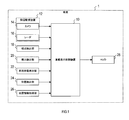
- FIG. 1 is a block diagram illustrating a configuration of an in-vehicle display system according to the embodiment.
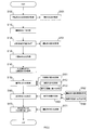
- FIG. 2 is a flowchart showing the procedure of the display control process.
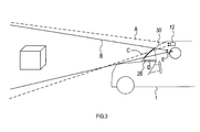
- FIG. 3 is an explanatory diagram illustrating the relationship among the field of view of the periphery monitoring device, the field of view of the driver, the HUD projection surface, and the HUD display surface.
- in-vehicle display system The configuration of the in-vehicle display system according to the embodiment will be described with reference to FIG.
- This in-vehicle display system is a system that presents information to a driver using a HUD, and is mounted on the vehicle 1.
- the in-vehicle display system includes an in-vehicle display control device 10 and each unit connected to the in-vehicle display control device 10.
- the in-vehicle display control device 10 includes a periphery monitoring device 12, a viewpoint detection unit 18, a visual acuity detection unit 20, a vehicle behavior detection unit 22, a position detection unit 24, a map information acquisition unit 26, and a head-up display projector (hereinafter referred to as a HUD projector). ) 28 is connected.
- a HUD projector head-up display projector
- the in-vehicle display control device 10 is an information processing device mainly configured by a semiconductor memory (not shown) such as a CPU, RAM, ROM, flash memory, and an input / output interface.
- the vehicle-mounted display control device 10 forms a display image with a virtual image in the driver's front field of view by the HUD projector 28, thereby providing information on the actual scenery seen by the driver through the windshield provided in front of the driver's seat of the vehicle 1. Overlapping display.
- the in-vehicle display control device 10 is embodied by, for example, a microcontroller or the like in which functions as a computer system are integrated.
- the function of the in-vehicle display control device 10 is realized by the CPU executing a program stored in a substantial storage medium such as a ROM or a semiconductor memory.
- the number of microcontrollers constituting the in-vehicle display control device 10 may be one or more.
- the method for realizing the function of the in-vehicle display control device 10 is not limited to software, and some or all of the elements may be realized using hardware in which a logic circuit, an analog circuit, or the like is combined.
- the periphery monitoring device 12 is an optical or electromagnetic sensor for recognizing the scenery in front of the vehicle 1.
- the periphery monitoring device 12 includes, for example, a camera 14 and a radar 16.
- the camera 14 captures the front area of the vehicle 1 that can be seen through the windshield and outputs data of the captured image to the in-vehicle display control device 10.
- the radar 16 transmits radio waves and laser light toward a front area common to the imaging range of the camera 14 and receives the reflected waves to detect the presence / absence of the object and the distance to the object.
- an objective sensor such as an infrared sensor or an ultrasonic sensor may be used as the periphery monitoring device 12.
- the viewpoint detection unit 18 is a sensor having a function of detecting the position of the driver's eyes.
- a camera system having a function of measuring the coordinates of the driver's eye position in the viewpoint vehicle coordinate system can be applied.
- the camera system detects the coordinates of the position of the driver's eye in the vehicle coordinate system by performing image processing on the image of the driver's eye captured by the infrared camera.
- the visual acuity detection unit 20 is a device that detects the state of visual acuity of the driver.
- the visual acuity detection unit 20 it is conceivable to implement an autorefractometer function in cooperation with a known driver status monitor that recognizes a driver's face image using an infrared camera and a computer.
- the autorefractometer is a well-known measuring device that applies infrared light to a subject's eye and automatically analyzes and measures the refractive state of the eye and the presence and degree of myopia, hyperopia, astigmatism, and the like.
- the vehicle behavior detection unit 22 is a sensor for detecting a physical quantity representing the behavior of the vehicle 1.
- the vehicle behavior detection unit 22 includes a gyroscope, a suspension stroke sensor, a vehicle height sensor, a wheel speed sensor, an acceleration sensor, and the like.
- the position detection unit 24 is for detecting the current location of the vehicle 1 based on detection results by a GPS receiver, a gyroscope, a vehicle speed sensor, and the like.
- the map information acquisition unit 26 acquires terrain data including information representing the terrain, road shape, and the like in the coordinates of the absolute coordinate system, and outputs the acquired terrain data to the in-vehicle display control device 10.
- the terrain data acquired by the map information acquisition unit 26 may be recorded in a map information storage medium mounted on the vehicle 1 or acquired by communication with an external device. Good.
- the HUD projector 28 is a display device that projects light constituting information to be displayed to the driver onto the windshield and forms a virtual display image in the driver's front field of view.
- a projector having a structure in which a display panel that displays image information to be projected directly faces a windshield as a projection surface can be used as appropriate.
- a projector having a structure for projecting image information from the display panel via an optical system including a mirror, a lens, and the like can be used as appropriate.
- the in-vehicle display control device 10 controls the position where the display image is projected based on the position of the object recognized by the periphery monitoring device 12 and the position of the driver's eyes. Specifically, the in-vehicle display control device 10 projects the display image so that the display image of the HUD is superimposed on a specific object in the driver's field of view.
- the in-vehicle display control device 10 is configured to perform control for appropriately displaying the HUD display image with respect to the following factors (1) to (7).
- the in-vehicle display control device 10 acquires three-dimensional information of the foreground from the viewpoint position of the periphery monitoring device 12. Specifically, as illustrated in FIG. 3, the in-vehicle display control device 10 uses a visual field space A that is a visual field based on the viewpoint position (that is, the installation position) of the periphery monitoring device 12 in the absolute coordinate system. Get the coordinates of a 3D object.
- the in-vehicle display control device 10 calculates coordinates in the visual field A based on the camera image information and / or radar detection information acquired by the periphery monitoring device 12.
- the information acquired by the periphery monitoring device 12 in a state where the pitch, roll, and yaw are not generated, the ground height of the periphery monitoring device 12, and Coordinates in the visual field space A are calculated using known parameters representing the mounting angle and the like. Even if the pitch of the vehicle 1 is changing, if the frequency of the fluctuation is not more than the specified position, it is assumed that no pitch fluctuation has occurred, and the coordinates are calculated by the first method. And
- the in-vehicle display control device 10 calculates the coordinates in the visual field space A based on the topographic data around the current location acquired by the map information acquisition unit 26.
- This terrain data presupposes that objects such as terrain and roads are recorded in the coordinates of the absolute coordinate system.
- the in-vehicle display control device 10 represents the coordinates represented by the acquired terrain data, the coordinates of the current location of the vehicle 1 detected by the position detection unit 24, the ground height and the mounting angle of the periphery monitoring device 12, and the like. Coordinates in the visual field space A are calculated using known parameters.
- the first method is basically applied.
- the first method considering that a moving object can be an object to be observed, the coordinates of the time when the change of pitch, roll, yaw, etc. occurs and the object is not the object of observation are the past observed. It is assumed that the prediction is made from the coordinates of a plurality of times.
- the in-vehicle display control device 10 analyzes the environmental properties of the information acquired by the periphery monitoring device 12 in S100. Specifically, the in-vehicle display control device 10 performs brightness and color of ambient light, weather (for example, rain / snow), a color of a superimposed object (for example, a color of a vehicle), by image processing on image information of the camera. And the visibility of the superimposed object is recognized. Note that S101 is processing related to the countermeasure to the above-mentioned “(3) Factors related to compatibility between HUD display image and environmental properties”.
- the in-vehicle display control device 10 specifies the superimposed shape A1 based on the three-dimensional information acquired in S100.
- the superimposed shape A1 is the position and shape in the visual field space A of the display image to be displayed superimposed on a specific superimposed object.
- the in-vehicle display control device 10 detects specific superimposed objects such as lane markings, vehicles ahead, and road signs marked on the road from the information on the foreground landscape acquired by the surrounding monitoring device 12. To detect. Then, the position and shape of the display image in the coordinate system of the visual field A are superimposed so that the display image corresponding to the detected superimposition object overlaps the position of the superimposition object as viewed from the viewpoint of the periphery monitoring device 12. It is specified as A1.
- the in-vehicle display control device 10 acquires the eye position as the driver's viewpoint position based on the information acquired by the viewpoint detection unit 18. Specifically, the in-vehicle display control device 10 obtains the driver's viewpoint position as coordinates in a relative coordinate system based on, for example, the mounting position of the infrared camera constituting the viewpoint detection unit 18 or a predetermined position in the vehicle 1. To do.
- the vehicle-mounted display control device 10 acquires information representing the driver's visual acuity based on the detection result by the visual acuity detection unit 20. Specifically, the in-vehicle display control device 10 acquires the presence / absence and degree of myopia, hyperopia, astigmatism, and the eye refraction state as information representing the driver's visual acuity.
- S121 is processing related to the countermeasure to the above-mentioned “(5) Factors related to the physical ability of the driver”. If the response to changes in visual acuity that changes from moment to moment is omitted, the processing of S121 is not required to be performed periodically, and may be configured to be performed only once. Further, instead of actually measuring the visual acuity by the visual acuity detection unit 20, information on the visual acuity of the driver registered in advance may be read and acquired.
- the in-vehicle display control device 10 acquires the superimposed shape A2 corresponding to the driver's visual field B for the superimposed shape A1 specified in S110.
- the visual field B is a visual field based on the start position E of the driver as illustrated in FIG.
- the in-vehicle display control device 10 converts the coordinates of the superimposed shape A1 specified in S110 into a coordinate system based on the viewpoint position of the driver acquired in S120, thereby superimposing the shape A2. Is calculated.
- the superimposed shape A2 represents the position and shape of the display image in the visual field space B.
- a known view conversion method may be used.
- View conversion is a method for expressing a figure viewed from the position of the viewpoint for viewing the figure by moving it to another place in the three-dimensional space.
- the view conversion is a coordinate conversion that moves a figure to a coordinate system (that is, a viewpoint coordinate system) viewed from the position and direction of the viewpoint.
- this is a combination of coordinate transformation that translates the position of the figure in accordance with the coordinates of the viewpoint using the parallel transformation matrix and coordinate transformation that rotates the figure toward the viewpoint using the rotation transformation matrix.
- the superimposed shape A2 is specified so that the display image of the HUD is superimposed on the superimposed object as viewed from the driver's viewpoint.
- the in-vehicle display control device 10 acquires the position and shape of the display frame in the projection plane space C.
- the display frame is a frame that represents a predetermined range in which a display image can be displayed in accordance with the displacement of the superimposed object.
- the display frame is drawn so as to surround the display image.
- the projection plane space C is a coordinate system assigned to a range in which video light output from the HUD projector 28 is projected on the windshield 30 of the vehicle 1.
- the in-vehicle display control device 10 acquires a superimposed shape A3 corresponding to the projection plane space C for the superimposed shape A2 acquired in S130. Specifically, the in-vehicle display control device 10 converts the coordinates of the superimposed shape A2 into a two-dimensional coordinate system assigned on the windshield along a projection line connecting the viewpoint position of the driver and the superimposed shape A2. . In this way, the in-vehicle display control device 10 calculates the superimposed shape A3 that represents the position and shape of the display image in the projection plane space C.
- Perspective projection is a method for drawing on a two-dimensional plane as if a three-dimensional object was viewed. That is, in perspective projection, the apparent size of an object is inversely proportional to the distance. Specifically, if the viewpoint is the origin and the line of sight is in the negative direction on the z-axis perpendicular to the xy plane, the point at the position (x, y, z) is Projected to the position ( ⁇ Ax / z, ⁇ Ay / z) in the forward direction at the position.
- the in-vehicle display control device 10 is configured to correct the display mode for the superimposed shape A3 by executing the processes of S151, S152, and S153 described below.
- the in-vehicle display control device 10 reflects the distortion of the superimposed object on the display mode of the superimposed shape A3. Note that S151 is processing related to the countermeasure to the above-mentioned “(2) Factors related to variation in superimposed objects”. Specifically:
- a HUD display image is superimposed and displayed on a dividing line that divides a road lane.
- the marking lines on the road are drawn so that there is no sudden change using straight lines, clothoid curves, etc., in order to prevent sudden changes in the behavior of vehicles traveling along the driving lane. It is common.
- the display image of the HUD displayed superimposed on such a dividing line is generally expressed by converting a predetermined figure made of a straight line, a clothoid curve, etc. into a shape that matches the driver's viewpoint. is there.
- the road surface on which the marking line is marked is not necessarily a clean plane and may be uneven or distorted. In such a case, there is a possibility that a position or shape shift may occur between the actual landscape and the HUD display image. Therefore, the in-vehicle display control device 10 recognizes the shape of the ground surface using a radar, a camera, an ultrasonic sensor, an infrared sensor, or the like. If the recognized ground surface has a distortion or variation in shape that exceeds an allowable value, the superimposed shape A3 to be superimposed on the ground surface is deformed in accordance with the ground surface distortion or variation. By doing so, even when there is distortion or variation on the ground surface, the display of the HUD adapted to the actual landscape is continued.
- the vehicle-mounted display control device 10 uses a point where a line from the driver's viewpoint position in the vehicle traveling direction intersects the horizon as a reference point, and gradually increases the upper limit of distortion according to the distance from this reference point. Increase By doing so, it is possible to accurately transmit HUD information in the vicinity of the center of the driver's visual field, and to reduce the deviation between the actual scenery and the HUD display image in the vicinity of the driver's visual field.
- the in-vehicle display control device 10 reflects the environmental properties in the display mode of the superimposed shape A3. Note that S152 is processing related to countermeasures for the above-mentioned “(4) Factors related to compatibility between HUD display image and environmental properties”. Specifically:
- the in-vehicle display control device 10 corrects the display mode of the superimposed shape A3 according to the analysis result of the environmental information in S101. Specifically, the in-vehicle display control device 10 determines the color of the superimposition object, and emphasizes the contrast by changing the color of the HUD display image to a color different from that of the superimposition object. For example, if the superimposed object is a white vehicle, the in-vehicle display control device 10 changes the color of the HUD display image to yellow. Moreover, when superimposing the information showing a warning with respect to a yellow vehicle, the vehicle-mounted display control apparatus 10 does not use yellow for the display image of HUD, but uses other colors, such as a yellow complementary color.
- the in-vehicle display control device 10 determines the color of the ambient light and the weather, and adjusts the color of the HUD display image according to the environment. For example, during snowfall, the in-vehicle display control device 10 changes the original white display to another color. Further, when the ambient light looks red due to sunset or the like, the in-vehicle display control device 10 creates a real feeling by adding redness to the display image of the HUD.
- the in-vehicle display control device 10 is configured to perform a display simulating the shape of the superimposed object itself from the display image of the HUD when it is determined that the visibility of the superimposed object is poor from the analysis result of the environmental information. May be. By doing in this way, the visibility of a superposition target object can be supplemented. Specifically, in a situation where visibility is poor due to rain or fog, when the HUD is superimposed on the assumption that there is a lane marking, the vehicle-mounted display control device 10 displays a display that simulates the lane itself. It is possible to do it. By doing in this way, the effective augmented reality by HUD is realizable without being influenced as much as possible by the quality of a visual field.
- S153 the in-vehicle display control device 10 performs a countermeasure regarding the moving expression of the display image of the HUD. Note that S153 is processing related to the above-mentioned “(6) Consideration for imperfection of countermeasures”. Specifically:
- the in-vehicle display control device 10 performs the entire display control process in a period that can be realized.
- the in-vehicle display control device 10 adds an afterimage expression when moving the display image of the HUD. By doing so, it is possible to make the driver perceive the movement of the display image of the HUD as a smooth movement, and the effect of reducing the burden on the eyes of the driver can be expected.
- the in-vehicle display control device 10 sets a margin part that is a room for the display image not being completely visible in the outer peripheral part of the displayable area of the HUD. And the vehicle-mounted display control apparatus 10 produces
- a determination means for detecting a delay is provided in the in-vehicle display control device 10. If it is detected that a delay occurs, the in-vehicle display control device 10 does not update the display itself at that time.
- the in-vehicle display control device 10 acquires the display shape C4 corresponding to the display surface space D of the HUD projector 28 for the superimposed shape A3 acquired in S150.
- the display surface space D is a two-dimensional coordinate system assigned to the image display area in the display panel of the HUD projector 28, as illustrated in FIG.
- the in-vehicle display control apparatus 10 converts the two-dimensional coordinates of the superimposed shape A3 into the two-dimensional display surface space D according to the characteristics such as the curvature of the projection surface space C and the refractive index of the optical path of the HUD projector 28. Convert coordinates to coordinate system.
- the in-vehicle display control device 10 calculates the display shape C4 representing the position and shape of the display image in the display surface space D. This coordinate transformation is calculated using, for example, a transformation matrix between two planes of the projection plane space C and the image display area.
- the in-vehicle display control device 10 is configured to correct the display mode for the display shape C4 by executing the processes of S161, S162, and S163 described below.
- the in-vehicle display control device 10 reflects the change in the behavior of the vehicle 1 in the display mode of the display shape C4. Note that S161 is processing related to the countermeasure to the above-mentioned “(1) Factors related to vehicle behavior”. Specifically:
- the in-vehicle display control device 10 detects a vehicle rotation angle such as a pitch angle, a roll angle, and a yaw angle of the vehicle 1 based on information acquired by the vehicle behavior detection unit 22, the camera 14, and the radar 16. And the relative position with respect to the real scenery of the vehicle 1 is estimated using together the detected vehicle rotation angle and detection results, such as a wheel speed sensor and an acceleration sensor. And the vehicle-mounted display control apparatus 10 estimates the deviation
- a vehicle rotation angle such as a pitch angle, a roll angle, and a yaw angle of the vehicle 1 based on information acquired by the vehicle behavior detection unit 22, the camera 14, and the radar 16.
- the relative position with respect to the real scenery of the vehicle 1 is estimated using together the
- the in-vehicle display control device 10 reflects the driver's adaptation factor for the processing in S161.
- S162 is processing related to the countermeasure to the above-mentioned “(3) Factors relating to human adaptation to vehicle behavior”. Specifically:
- the in-vehicle display control device 10 analyzes the time transition of the pitch angle as a frequency component, and performs a high-pass filter process corresponding to a predetermined lower limit frequency region. Thereby, the in-vehicle display control device 10 excludes the correction of the display shape C4 from a gentle pitch change lower than the frequency range of the high-pass filter. In this way, the driver's adaptation to a gradual pitch change can be reflected in the display mode of the HUD display image.
- the in-vehicle display control device 10 implements measures for reducing the processing load for the processing in S161.
- S163 is processing related to the above-mentioned “(7) Consideration for reduction in processing load”. Specifically:
- the in-vehicle display control device 10 is used to change behavior in a frequency range that exceeds a limit value (for example, about 30 to 50 Hz) of a frequency at which humans can recognize blinking. Does not correct the display shape C4.
- a limit value for example, about 30 to 50 Hz
- the in-vehicle display control device 10 analyzes temporal transitions of the vehicle posture such as the pitch angle, the roll angle, and the yaw angle as frequency components, and performs a low-pass filter process corresponding to a predetermined upper limit frequency range. Thereby, the vehicle-mounted display control apparatus 10 does not correct the display shape C4 for a behavior change in a frequency range that cannot be recognized by a human. In this way, the processing load can be reduced by omitting the processing for an unnecessary behavior change that cannot be recognized by a human.
- the in-vehicle display control device 10 may be configured to stop the display mode correction or the HUD display itself. This is effective from the viewpoint of reducing processing load and power consumption.
- the in-vehicle display control device 10 outputs the display shape C4 acquired in S160 to the display panel of the HUD projector 28. Thereby, the display shape C4 is projected from the HUD projector 28 onto the windshield 30, and a display image recognized in front of the driver's field of view is formed.
- the in-vehicle display control device 10 is configured to correct the display mode for the display shape C4 by executing the process of S171 described below.
- the vehicle-mounted display control device 10 reflects the measurement result of the driver's visual acuity in the display mode of the display shape C4. Note that S171 is processing related to the countermeasure to the above-mentioned “(5) Factors related to the physical ability of the driver”. Specifically:
- the vehicle-mounted display control device 10 is based on the information on the driver's visual acuity acquired in S121, and the display image of the HUD from the driver according to the quality of visual acuity and the degree of refractive abnormality such as myopia, hyperopia, astigmatism And the brightness of the HUD display image are adjusted. By doing in this way, it is possible to cope with individual differences in visual acuity for each driver and situations where the visual acuity changes from moment to moment due to fatigue or the like in the same driver.
- the vehicle-mounted display system has the following effects.
- various factors that may cause a deviation or discomfort between the display image of the HUD and the actual scenery depending on the situation such as the behavior of the vehicle, the nature of the external environment, the physical ability of the driver, etc.
- the display mode of the HUD display image can be adjusted. This can reduce display image incompatibility and discomfort in the HUD.
- the processing of S100 executed by the in-vehicle display control device 10 corresponds to processing as a spatial information acquisition unit.
- the process of S120 executed by the in-vehicle display control device 10 corresponds to the process as the viewpoint information acquisition unit.
- the processing of S110, S130, S150 to S153, S160 to S163, and S171 executed by the in-vehicle display control device 10 corresponds to processing as a display control unit.
- the process of S170 executed by the in-vehicle display control device 10 corresponds to a process as an output unit.
- the processing of S161 executed by the in-vehicle display control device 10 corresponds to behavior related control.
- the processing of S101, S151, and S152 executed by the in-vehicle display control device 10 corresponds to environment-related control.
- the processing of S121 and S171 executed by the in-vehicle display control device 10 corresponds to physical ability related control.
Abstract
車載表示制御装置(10)は、車両(1)の運転者に対して表示すべき情報を運転者の視界前方において認識される虚像からなる表示像として表示するHUD(28)を制御する。この車載表示制御装置は、挙動関連制御、環境関連制御、及び身体能力関連制御の少なくとも何れかの制御を実行するように構成されている。挙動関連制御は、車両の挙動を表す情報に基づいてHUDの表示像の表示態様を調節する制御である。環境関連制御は、外部環境の性状を現す情報に基づいてHUDの表示像の表示態様を調節する制御である。身体能力関連制御は、運転者の身体能力を表す情報に基づいてHUDの表示像の表示態様を調節する制御である。
Description
本国際出願は、2016年10月7日に日本国特許庁に出願された日本国特許出願第2016-199185号に基づく優先権を主張するものであり、日本国特許出願第2016-199185号の全内容を本国際出願に参照により援用する。
本開示は、車両に搭載されるヘッドアップディスプレイによる表示を制御する車載表示制御装置に関する。
従来、自動車の運転者の前方視界に虚像による表示像を形成することにより、運転者の視線の先に情報を表示する、いわゆるヘッドアップディスプレイが知られている。以下、ヘッドアップディスプレイをHUDと表記する。車両に搭載されるHUDの実用例として、いわゆる拡張現実がある。車両に搭載されるHUDを用いた拡張現実では、例えば、車両のウインドシールド越しに見える実風景に情報を重ねて表示することで、運転者が認識する実風景を拡張する。一例では、交差点において自車両が進むべき進路方向を示す矢印等の図柄を、実風景の道路の形状に合わせて表示させる。あるいは、運転者が見ていない道路標識に対して強調表示を施すことで注意を喚起する。
しかしながら、車両内において運転者の顔の位置は必ずしも固定された位置にあるわけではない。運転者の顔の位置が変化することで、運転者の視界において実風景とHUDの表示像との位置にずれが生じてしまい、重畳表示の利点を活かせない場合がある。さらには、HUDの表示像が適切な位置に表示されないことで、運転者に違和感や誤解を与えるといった問題が生じることがある。
上述のような問題に対して、特許文献1には、次のような技術が開示されている。すなわち、運転者の眼の位置を検出し、運転者の眼の位置と道路上の誘導経路とを結ぶ直線状に表示像を結像させることにより、HUDの表示像を適切な位置に表示する。
しかしながら、発明者の詳細な検討の結果、HUDの表示像が実風景とずれて表示される要因は、運転者の顔の位置に関するものだけに限らないという課題が見出された。例えば、発明者は、車両の挙動の急激な変化、外部環境の性状、及び運転者の身体能力等に関する様々な要因によって、HUDの表示像と実風景とのずれが生じる可能性があることを見出した。また、発明者は、これらの要因によりHUDの表示像と実風景との不適合が生じ、運転者が違和感を覚える場合もあることを見出した。
本開示の一局面は、HUDの表示像と実風景とのずれや違和感を生じる様々な要因に対して、HUDの表示像を適切に表示するための技術を提供することが好ましい。
本開示の一態様に係る車載表示制御装置は、ヘッドアップディスプレイを制御するものである。このヘッドアップディスプレイは、車両の運転者に対して表示すべき情報を運転者の視界前方において認識される虚像からなる表示像として表示する。車載表示制御装置は、空間情報取得部と、視点情報取得部と、表示制御部と、出力部とを備える。
本開示の一態様に係る車載表示制御装置は、ヘッドアップディスプレイを制御するものである。このヘッドアップディスプレイは、車両の運転者に対して表示すべき情報を運転者の視界前方において認識される虚像からなる表示像として表示する。車載表示制御装置は、空間情報取得部と、視点情報取得部と、表示制御部と、出力部とを備える。
空間情報取得部は、車両の前方の実風景に存在する物体の絶対座標系における位置を表す情報を取得するように構成されている。視点情報取得部は、運転者の眼の位置を表す情報を取得するように構成されている。表示制御部は、物体の位置の情報と眼の位置の情報とに基づいて、表示像の表示態様を決定するように構成されている。具体的には、表示制御部は、運転者の視界において特定の対象物に表示像が重畳して表示されるように、表示像を投影する位置を少なくとも含む表示像の表示態様を決定する。出力部は、表示制御部によって決定された表示態様に従って、ヘッドアップディスプレイに表示像を形成させるように構成されている。
また、表示制御部は、挙動関連制御、環境関連制御、及び身体能力関連制御の少なくとも何れかの制御を実行するように構成されている。挙動関連制御は、車両の挙動を表す情報に基づいて表示像の表示態様を調節する制御である。環境関連制御は、外部環境の性状を現す情報に基づいて表示像の表示態様を調節する制御である。身体能力関連制御は、運転者の身体能力を表す情報に基づいて表示像の表示態様を調節する制御である。
本開示に係る車載表示制御装置によれば、HUDの表示像と実風景とのずれや違和感を生じ得る様々な要因に応じて、表示像の表示態様を調節することができる。したがって、HUDにおける表示像の不適合や違和感を低減できる。
本開示についての上記目的及びその他の目的、特徴や利点は、添付の図面を参照しながら下記の詳細な記述により、より明確になる。その図面の概要は次のとおりである。
図1は、実施形態の車載表示システム構成を表すブロック図である。
図2は、表示制御処理の手順を表すフローチャートである。
図3は、周辺監視装置の視界、運転者の視界、HUD投影面、HUD表示面の関係を表す説明図である。
以下、本開示の実施形態を図面に基づいて説明する。なお、本開示は下記の実施形態に限定されるものではなく様々な態様にて実施することが可能である。
[車載表示システムの構成の説明]
実施形態の車載表示システムの構成について、図1を参照しながら説明する。この車載表示システムは、HUDを用いて運転者に情報を提示するシステムであり、車両1に搭載されている。図1に例示されるとおり、車載表示システムは、車載表示制御装置10と、この車載表示制御装置10に接続される各部を含んで構成されている。車載表示制御装置10には、周辺監視装置12、視点検出部18、視力検出部20、車両挙動検出部22、位置検出部24、地図情報取得部26、及びヘッドアップディスプレイプロジェクタ(以下、HUDプロジェクタ)28が接続される。
[車載表示システムの構成の説明]
実施形態の車載表示システムの構成について、図1を参照しながら説明する。この車載表示システムは、HUDを用いて運転者に情報を提示するシステムであり、車両1に搭載されている。図1に例示されるとおり、車載表示システムは、車載表示制御装置10と、この車載表示制御装置10に接続される各部を含んで構成されている。車載表示制御装置10には、周辺監視装置12、視点検出部18、視力検出部20、車両挙動検出部22、位置検出部24、地図情報取得部26、及びヘッドアップディスプレイプロジェクタ(以下、HUDプロジェクタ)28が接続される。
車載表示制御装置10は、図示しないCPU、RAM、ROM、フラッシュメモリ等の半導体メモリ、及び入出力インタフェース等を中心に構成された情報処理装置である。車載表示制御装置10は、HUDプロジェクタ28によって運転者の前方視界に虚像による表示像を形成することにより、車両1の運転席前方に設けられたウインドシールド越しに運転者が見る実風景に情報を重ねて表示する。
車載表示制御装置10は、例えば、コンピュータシステムとしての機能が集約されたマイクロコントローラ等により具現化される。車載表示制御装置10の機能は、CPUがROMや半導体メモリ等の実体的な記憶媒体に格納されたプログラムを実行することにより実現される。なお、車載表示制御装置10を構成するマイクロコントローラの数は1つでも複数でもよい。また、車載表示制御装置10の機能を実現する手法はソフトウェアに限るものではなく、その一部又は全部の要素を論理回路やアナログ回路等を組合せたハードウェアを用いて実現してもよい。
周辺監視装置12は、車両1の前方風景を認識するための光学的あるいは電磁的なセンサである。この周辺監視装置12は、例えば、カメラ14及びレーダ16により構成される。カメラ14は、車両1のウインドシールド越しに見える前方領域を撮影し、撮影された画像のデータを車載表示制御装置10に出力する。レーダ16は、カメラ14の撮影範囲と共通の前方領域に向けて電波やレーザ光を発信し、その反射波を受信することにより対象物の有無や対象物までの距離を検出する。また、カメラ14やレーダ16の他に、赤外線センサや超音波センサ等の対物センサを周辺監視装置12として用いてもよい。
視点検出部18は、運転者の眼の位置を検出する機能を有するセンサである。検出部18としては、例えば、視点車両座標系における運転者の眼の位置の座標を測定する機能を有するカメラシステム等を適用することができる。このカメラシステムは、例えば、赤外線カメラにより撮像された運転者の眼の画像に画像処理を施すことにより、車両座標系における運転者の眼の位置の座標を検出する。
視力検出部20は、運転者の視力の状態を検出する装置である。視力検出部20の具体例としては、赤外線カメラとコンピュータにより運転者の顔画像を認識する周知のドライバステータスモニタと連携し、オートレフラクトメータの機能を実装することが考えられる。オートレフラクトメータとは、被験者の眼に赤外線光を当て、眼の屈折状態や、近視・遠視・乱視等の有無や度合いを自動的にコンピュータで解析して計測する周知の計測機器である。
車両挙動検出部22は、車両1の挙動を表す物理量を検出するためのセンサである。この車両挙動検出部22は、ジャイロスコープ、サスペンションストロークセンサ、車高センサ、車輪速センサ、及び加速度センサ等によって構成される。位置検出部24は、GPS受信機、ジャイロスコープ、及び車速センサ等による検出結果に基づき、車両1の現在地を検出するためのものである。
地図情報取得部26は、地形や道路形状等を絶対座標系の座標で表した情報が含まれた地形データを取得し、その取得された地形データを車載表示制御装置10に出力する。地図情報取得部26により取得される地形データは、車両1に搭載された地図情報記憶媒体に収録されているものであってもよいし、外部装置との通信により取得されるものであってもよい。
HUDプロジェクタ28は、運転者に対して表示すべき情報を構成する光をウインドシールドに投射し、運転者の前方視界に虚像による表示像を形成する表示装置である。HUDプロジェクタ28として、例えば、投影される画像情報を表示する表示パネルが、投影面としてのウインドシールドに直接対面する構造のプロジェクタを適宜利用できる。あるいは、表示パネルからミラーやレンズ等からなる光学系を介して画像情報を投影する構造のプロジェクタ等を適宜利用できる。
車載表示制御装置10は、周辺監視装置12により認識された物体の位置と、運転者の眼の位置と基づいて、表示像を投影する位置を制御する。具体的には、車載表示制御装置10は、運転者の視界において特定の対象物にHUDの表示像が重畳して表示されるように、表示像を投影する。車載表示制御装置10は、次の(1)~(7)の要因に関して、HUDの表示像を適切に表示するための制御を行うように構成されている。
(1)車両の挙動に関する要因
HUDは車両に取付けられた機構において表示されるものである。そのため、車両のピッチ、ロール、及びヨー等の急激な変化が発生した場合に、表示像のぶれ等に起因するHUD酔い等の悪影響を運転者に与えるおそれがある。このような悪影響は、HUDの表示像の焦点距離が遠距離である場合に顕著である。このような問題は、ウインドシールド越しに見える実風景に対して運転者の視線が合っている状態から、そこに重畳表示されていたHUDの表示像が突発的にずれることにより、運転者の脳において違和感として認識されることに起因すると推測される。
HUDは車両に取付けられた機構において表示されるものである。そのため、車両のピッチ、ロール、及びヨー等の急激な変化が発生した場合に、表示像のぶれ等に起因するHUD酔い等の悪影響を運転者に与えるおそれがある。このような悪影響は、HUDの表示像の焦点距離が遠距離である場合に顕著である。このような問題は、ウインドシールド越しに見える実風景に対して運転者の視線が合っている状態から、そこに重畳表示されていたHUDの表示像が突発的にずれることにより、運転者の脳において違和感として認識されることに起因すると推測される。
(2)重畳対象物のばらつきに関する要因
例えば、道路面上に走行レーンの区分等を表す図柄を重畳表示するケースにおいて、道路面に凸凹等のばらつきや歪みあることにより、HUDの表示像の形状と実風景内の重畳対象物の形状とが適合せず、表示のずれが発生する場合がある。このように、重畳対象物の形状の歪みに起因してHUDの表示像と実風景とのずれが生じ、HUD酔い等を誘発するおそれがある。
例えば、道路面上に走行レーンの区分等を表す図柄を重畳表示するケースにおいて、道路面に凸凹等のばらつきや歪みあることにより、HUDの表示像の形状と実風景内の重畳対象物の形状とが適合せず、表示のずれが発生する場合がある。このように、重畳対象物の形状の歪みに起因してHUDの表示像と実風景とのずれが生じ、HUD酔い等を誘発するおそれがある。
(3)車両の挙動への人の適応に関する要因
車両の挙動の変化について、例えば、勾配が一定の坂路やバンクを走行する時のように、定常的な姿勢変化に対して運転者が姿勢を合わせるなどして適応可能な場合、上記(1)の要因における挙動の変化とは区別してHUDの表示態様を調節する必要がある。
車両の挙動の変化について、例えば、勾配が一定の坂路やバンクを走行する時のように、定常的な姿勢変化に対して運転者が姿勢を合わせるなどして適応可能な場合、上記(1)の要因における挙動の変化とは区別してHUDの表示態様を調節する必要がある。
(4)HUDの表示像と環境の性状との相性に関する要因
HUDの表示像は、風景内に半透過的に表示されるものであるため、例えば、天気、環境光の色・明るさ、重畳対象物の色、及び見通し等の周辺環境の性状によって、見栄えにばらつきが生じるという問題がある。
HUDの表示像は、風景内に半透過的に表示されるものであるため、例えば、天気、環境光の色・明るさ、重畳対象物の色、及び見通し等の周辺環境の性状によって、見栄えにばらつきが生じるという問題がある。
(5)運転者の身体能力に関する要因
運転者の身体能力に個人差があることによって、HUDの表示像の見え方に差が生じる場合がある。例えば、運転者の身体能力の一つとしての視力に関して、運転者が近視傾向であるか遠視傾向であるかによって、HUDの表示像を結像させる適切な焦点距離が異なるという問題がある。
運転者の身体能力に個人差があることによって、HUDの表示像の見え方に差が生じる場合がある。例えば、運転者の身体能力の一つとしての視力に関して、運転者が近視傾向であるか遠視傾向であるかによって、HUDの表示像を結像させる適切な焦点距離が異なるという問題がある。
(6)対策の不完全性に対する配慮
上記(1)~(5)の要因に対する対策を行うシステムには処理限界があるため、対策が不完全であることを前提とした工夫が肝要である。
上記(1)~(5)の要因に対する対策を行うシステムには処理限界があるため、対策が不完全であることを前提とした工夫が肝要である。
(7)処理負荷に軽減に関する配慮
上記(1)~(5)の要因に対する対策を行う処理は、一度の処理でも複数回の座標変換を伴うものである。また、対策のための処理が頻繁に発生する可能性があることから、システムの処理負荷が高くなるという問題がある。このような高い処理能力を実現するシステムは、高コストであるという問題に直結するため、処理負荷を軽減するための工夫が肝要である。
上記(1)~(5)の要因に対する対策を行う処理は、一度の処理でも複数回の座標変換を伴うものである。また、対策のための処理が頻繁に発生する可能性があることから、システムの処理負荷が高くなるという問題がある。このような高い処理能力を実現するシステムは、高コストであるという問題に直結するため、処理負荷を軽減するための工夫が肝要である。
[表示制御処理の手順の説明]
車載表示制御装置10のCPUがプログラムに従って実行する表示制御処理の手順について、図2のフローチャートを参照しながら説明する。この表示制御処理は、所定の制御周期ごとに繰返し実行される。
車載表示制御装置10のCPUがプログラムに従って実行する表示制御処理の手順について、図2のフローチャートを参照しながら説明する。この表示制御処理は、所定の制御周期ごとに繰返し実行される。
S100では、車載表示制御装置10は、周辺監視装置12の視点位置からの前風景の三次元情報を取得する。具体的には、車載表示制御装置10は、図3に例示されるように、周辺監視装置12の視点位置(すなわち、設置位置)を基準とする視野である視野空間Aについて、絶対座標系における三次元対象物の座標を取得する。
三次元対象物の絶対座標系の座標を取得する方法としては次のようにする。第1の方法として、車載表示制御装置10は、周辺監視装置12により取得されたカメラの画像情報及び/又はレーダの検出情報に基づいて視野空間Aにおける座標を算出する。第1の方法では、車両挙動検出部22と連携して、ピッチ、ロール、及びヨーの変動が発生してない状態で周辺監視装置12により取得された情報と、周辺監視装置12の地上高及び取付角度等を表す既知のパラメータとを用いて、視野空間Aにおける座標を算出する。なお、車両1のピッチが変化している場合であっても、その変動の周波数が規定位置以下である場合、ピッチの変動は発生していないものとして、第1の方法による座標の算出の対象とする。
第2の方法として、車載表示制御装置10は、地図情報取得部26により取得された現在地周辺の地形データに基づいて視野空間Aにおける座標を算出する。この地形データは、地形や道路等の対象物が絶対座標系の座標で記録されていることを前提とする。そして、車載表示制御装置10は、取得された地形データで表される座標と、位置検出部24により検出された車両1の現在地の座標と、周辺監視装置12の地上高及び取付角度等を表す既知のパラメータとを用いて、視野空間Aにおける座標を算出する。
ただし、上記第2の方法では、車両等の移動物に関する三次元情報は取得できない。そのため、移動物を対象にHUDの表示像を重畳表示することが前提となる場合、基本的には上記第1の方法を適用するものとする。また、上記第1の方法においては、移動物も観測対象となり得ることを考慮し、ピッチ、ロール、及びヨー等の変動が発生して観測対象外となる時間の座標は、観測されている過去の複数の時間の座標から予測するものとする。
図2のフローチャートの説明に戻る。S101では、車載表示制御装置10は、S100において周辺監視装置12により取得された情報について、環境の性状を解析する。具体的には、車載表示制御装置10は、カメラの画像情報に対する画像処理により、環境光の明るさや色、天気(例えば、降雨・降雪)、重畳対象物の色(例えば、車両の色)、及び重畳対象物の視認性を認識する。なお、S101は、上述の「(3)HUDの表示像と環境の性状との相性に関する要因」への対策に関連する処理である。
S110では、車載表示制御装置10は、S100において取得された三次元情報に基づいて、重畳形状A1を特定する。重畳形状A1は、特定の重畳対象物に重畳して表示すべき表示像の視野空間Aにおける位置及び形状である。具体的には、車載表示制御装置10は、周辺監視装置12により取得された前風景の情報から、例えば道路上に標示された区分線、前方車両、及び道路標識等の特定の重畳対象物を検出する。そして、検出された重畳対象物に対応する表示像が、周辺監視装置12の視点から見て重畳対象物の位置に重なるように、視野空間Aの座標系における表示像の位置及び形状を重畳形状A1として特定する。
S120では、車載表示制御装置10は、視点検出部18により取得された情報に基づいて、運転者の視点位置として眼の位置を取得する。具体的には、車載表示制御装置10は、例えば、視点検出部18を構成する赤外線カメラの取付位置や車両1内の所定位置を基準とする相対座標系における座標として運転者の視点位置を取得する。
S121では、車載表示制御装置10は、視力検出部20による検出結果に基づいて、運転者の視力を表す情報を取得する。具体的には、車載表示制御装置10は、運転者の視力を表す情報として、近視・遠視・乱視等の有無や度合い、眼の屈折状態を取得する。なお、S121は、上述の「(5)運転者の身体能力に関する要因」への対策に関連する処理である。なお、時々刻々変化する視力の変化への対応を省略するのであれば、S121の処理を周期的に行う必要はなく、最初の一度のみ実施するように構成してもよい。また、視力検出部20により視力を実測する代わりに、予め登録されている運転者の視力の情報を読出して取得するように構成してもよい。
S130では、車載表示制御装置10は、S110において特定された重畳形状A1について、運転者の視野空間Bに対応する重畳形状A2を取得する。視野空間Bとは、図3に例示されるように、運転者の始点位置Eを基準とする視野である。具体的には、車載表示制御装置10は、S110において特定された重畳形状A1の座標を、S120において取得された運転者の視点位置を基準とする座標系に座標変換することで、重畳形状A2を算出する。この重畳形状A2は、視野空間Bにおける表示像の位置及び形状を表す。この座標変換は、例えば、周知のビュー変換の手法を用いることが考えられる。ビュー変換とは、図形を見る視点の位置を三次元空間中の別の場所に移して、そこから見た図形を表現するための図法である。つまり、ビュー変換は、図形を視点の位置と方向から見た座標系(すなわち、視点座標系)に移す座標変換である。具体的には、平行変換行列を用いて図形の位置を視点の座標に合わせて平行移動させる座標変換と、回転変換行列を用いて図形を視点に向けて回転させる座標変換との組み合せからなる。この座標変換により、運転者の視点から見てHUDの表示像が重畳対象物に重畳されて表示されるように重畳形状A2が特定される。
S140では、車載表示制御装置10は、表示枠の投影面空間Cにおける位置及び形状を取得する。表示枠は、重畳対象物の変位に合わせて表示像を表示可能な所定の範囲を表す枠である。表示枠は、表示像を囲むようにして描画される。なお、投影面空間Cとは、図3に例示されるように、車両1のウインドシールド30上において、HUDプロジェクタ28から出力される映像光が投影される範囲に割当てられた座標系である。
S150では、車載表示制御装置10は、S130において取得された重畳形状A2について、投影面空間Cに対応する重畳形状A3を取得する。具体的には、車載表示制御装置10は、運転者の視点位置と重畳形状A2とを結ぶ投影線に沿って重畳形状A2の座標をウインドシールド上に割当てられた二次元座標系に座標変換する。このようにして、車載表示制御装置10は、投影面空間Cにおける表示像の位置及び形状を表す重畳形状A3を算出する。この座標変換は、例えば、周知の透視投影により、3点座標を持つ重畳形状A2を二次元座標系の仮想面上に投影する手法を用いることが考えられる。透視投影とは、三次元の物体を見たとおりに二次元平面上に描画するための図法である。つまり、透視投影では、物体の見かけの大きさが距離に反比例する。具体的には視点を原点とし、視線がxy平面に垂直なz軸上の負の方向を向いているとした場合、(x,y,z)の位置にある点は、視点から-Aの位置にある前方向の(-Ax/z,-Ay/z)の位置に投影される。なお、このS150において、車載表示制御装置10は、以下に説明するS151,S152,S153の各処理を実行することにより、重畳形状A3について表示態様を補正するように構成されている。
S151では、車載表示制御装置10は、重畳対象物の歪みを重畳形状A3の表示態様に反映する。なお、S151は、上述の「(2)重畳対象物のばらつきに関する要因」への対策に関連する処理である。具体的には次のようにする。
例えば、道路の走行レーンを区分する区分線に対して、HUDの表示像を重畳表示する事例について説明する。道路整備の観点において、道路上に標示する区分線は、走行レーンに沿って走行する車両の挙動を急変させないために、直線やクロソイド曲線等を用いて急峻な変化が発生しないように描かれているのが一般的である。このような区分線に対して重畳表示されるHUDの表示像も、直線やクロソイド曲線等からなる予め決められた図形を運転者の視点に合わせた形状に変換した表現とするのが一般的である。
しかしながら、区分線等が標示されている道路面は、必ずしも綺麗な平面であるとは限らず、凸凹があったり歪んだりすることがある。そのような場合、実風景とHUDの表示像との間で位置や形状のずれが発生するおそれがある。そこで、車載表示制御装置10は、レーダ、カメラ、超音波センサ、赤外線センサ等を用いて地表面の形状を認識する。認識された地表面に許容値を超える歪みや形状のばらつきがある場合には、地表面に重畳表示する重畳形状A3を、地表面の歪みやばらつきに合わせて変形させる。こうすることにより、地表面に歪みやばらつきがある場合でも、実風景と適合したHUDの表示が継続される。
ただし、重畳対象物の歪みの程度が甚だしい場合、その重畳対象物の歪みに合わせてHUDの表示像を変形させることで、情報としての意味合いを失う状態にまで歪みが酷くなるという問題がある。そのような問題への対策として、HUDの表示像に対して歪みの上限を設定するということが考えられる。しかしながら、単に歪みの上限を設定するだけでは、実風景と表示像とのズレが発生するという問題が再発することになる。
そこで、車載表示制御装置10は、運転者の視点位置から車両進行方向へと向かう線と、地平線とが交差する点を基準点とし、この基準点からの距離に応じて、徐々に歪みの上限を大きくする。このようにすることで、運転者の視野の中心付近においてHUDの情報を的確に伝達しつつ、運転者の視野の周辺においては実風景とHUD表示像とのずれを低減することができる。
S152では、車載表示制御装置10は、環境の性状を重畳形状A3の表示態様に反映する。なお、S152は、上述の「(4)HUDの表示像と環境の性状との相性に関する要因」への対策に関連する処理である。具体的には次のようにする。
車載表示制御装置10は、S101における環境情報の解析結果に応じて、重畳形状A3の表示態様を補正する。具体的には、車載表示制御装置10は、重畳対象物の色を判別し、HUDの表示像の色を当該重畳対象物とは異なる色にしてコントラストを強調する。例えば、重畳対象物が白色の車両であれば、車載表示制御装置10は、HUDの表示像の色を黄色にする。また、黄色の車両に対して警告を表す情報を重畳する場合には、車載表示制御装置10は、HUDの表示像に黄色を使用せず、黄色の補色等の他の色を使用する。
また、車載表示制御装置10は、環境光の色や天気を判別し、HUDの表示像の色を環境に合わせて調節する。例えば、降雪時においては、車載表示制御装置10は、本来の白色の表示を他の色に変更する。また、夕焼け等により環境光が赤く見える場合、車載表示制御装置10は、HUDの表示像に赤みを加えることでリアル感を演出する。
さらには、車載表示制御装置10は、環境情報の解析結果から重畳対象物の視認性が悪いと判断した場合には、HUDの表示像により重畳対象物そのもの形状を模擬した表示を行うように構成されていてもよい。このようにすることで、重畳対象物の視認性を補完することができる。具体的には、降雨や霧等により視界が悪い状況において、走行レーンの区分線がある前提でHUDの重畳表示を行う場合には、車載表示制御装置10は、走行レーンそのものを模擬した表示を行うことが考えられる。このようにすることで、視界の良否に極力影響されずにHUDによる効果的な拡張現実を実現できる。
S153では、車載表示制御装置10は、HUDの表示像の移動表現に関する対策を行う。なお、S153は、上述の「(6)対策の不完全性に対する配慮」に関連する処理である。具体的には次のようにする。
システムの処理限界のため対策が不完全であるという前述の問題に対して、その不完全性を補完する処理を行うことで、問題を軽減することが可能となる。例えば、HUDの表示像の位置を、動的かつリアルタイムに人間が認知できる以上の速いリフレッシュレートで補正するということが理想ではある。しかしながら、システムによっては、速いリフレッシュレートでHUDの表示像の位置を補正するような高速な処理を実現できないことがある。そのような場合には、車載表示制御装置10は、表示制御処理全体を実現可能な周期で実施する。それに加えて、車載表示制御装置10は、HUDの表示像を移動させる際に残像表現を加える。このようにすることで、HUDの表示像の移動を滑らかな動きとして運転者に知覚させることができ、ドライバの目への負担を軽減するという効果も期待できる。
また、HUDによる表示が可能な領域が有限である状況において、表示像の位置を移動させるということは、移動によって表示像が表示可能な領域から見切れてしまう可能性がある。そこで、車載表示制御装置10は、HUDの表示可能領域の外周部分に表示像が見切れないための余地となる余裕部分を設定する。そして、車載表示制御装置10は、余裕部分を除いた表示可能領域内に収まるようにHUDの表示像の基となる重畳形状A3を生成する。このようにすることで、HUDの表示像の移動が発生しても見切れを発生しづらくすることができる。
また、HUDの表示において重畳対象物への追従が間に合わない程の移動等が突発的に発生することが考えられる。そこで、次のような対策を行うことも有効である。すなわち、車載表示制御装置10において遅れを検出する判定手段を設ける。そして、遅れが発生することが検出された場合は、車載表示制御装置10は、その回は表示そのものを更新しない。
S160では、車載表示制御装置10は、S150において取得された重畳形状A3について、HUDプロジェクタ28の表示面空間Dに対応する表示形状C4を取得する。表示面空間Dとは、図3に例示されるように、HUDプロジェクタ28の表示パネルにおける画像表示領域に割当てられた二次元座標系である。具体的には、車載表示制御装置10は、投影面空間Cの曲率やHUDプロジェクタ28の光学経路の屈折率等の特性に応じて、重畳形状A3の二次元座標を表示面空間Dの二次元座標系に座標変換する。このようにして、車載表示制御装置10は、表示面空間Dにおける表示像の位置及び形状を表す表示形状C4を算出する。この座標変換は、例えば、投影面空間C及び画像表示領域の2平面間の変換行列を用いて演算される。なお、このS160において、車載表示制御装置10は、以下に説明するS161,S162,S163の各処理を実行することにより、表示形状C4について表示態様を補正するように構成されている。
S161では、車載表示制御装置10は、車両1の挙動の変化を表示形状C4の表示態様に反映する。なお、S161は、上述の「(1)車両の挙動に関する要因」への対策に関連する処理である。具体的には次のようにする。
車載表示制御装置10は、車両挙動検出部22、カメラ14、及びレーダ16により取得された情報に基づいて、車両1のピッチ角、ロール角、及びヨー角等の車両回転角を検出する。そして、検出された車両回転角と、車輪速センサや加速度センサ等の検出結果とを併用して、車両1の実風景に対する相対的な位置を推定する。そして、車載表示制御装置10は、推定された相対的な位置に基づいて補正前の表示形状C4による表示像と実風景とのずれ量を推定し、このずれ量を修正する。このようにすることで、車両1において一時的な挙動が発生しても、実風景とマッチしたHUDの表示が維持される。
S162では、車載表示制御装置10は、S161の処理について運転者の適応要因を反映する。なお、S162は、上述の「(3)車両の挙動への人の適応に関する要因」への対策に関連する処理である。具体的には次のようにする。
一定の勾配が連続する登坂や降坂を走行しているときのように、車両のピッチが定常的に傾いている場合には、運転者はその勾配に対して姿勢を合わせることにより適応することができる。これにより、実際には車両がピッチ方向に傾いた状態であっても、運転者の視野はピッチ角0度の状態と変わらないようにすることができる。このため、上述のS161において全てのピッチの変化に対して必ずしもHUDの表示像の表示態様を補正する必要があるわけではない。
そこで、車載表示制御装置10は、ピッチ角の時間的推移を周波数成分として解析し、所定の下限周波数域に対応するハイパスフィルタ処理を施す。これにより、車載表示制御装置10は、ハイパスフィルタの周波数域より低い緩やかなピッチの変化に対しては、表示形状C4の補正の対象外とする。このようにすることで、緩やかなピッチの変化に対する運転者の適応を、HUDの表示像の表示態様に反映させることができる。
S163では、車載表示制御装置10は、S161の処理について処理負荷を低減するための対策を実施する。なお、S163は、上述の「(7)処理負荷に軽減に関する配慮」に関連する処理である。具体的には次のようにする。
HUDによる拡張現実は人間が視覚で認識するものであるため、人間が点滅を認識可能な周波数の限界値(例えば、30~50Hz程度)を越える周波数域の挙動変化については、車載表示制御装置10が表示形状C4の補正を行わないようにする。
具体的には、車載表示制御装置10は、ピッチ角、ロール角、及びヨー角等の車両姿勢の時間的推移を周波数成分として解析し、所定の上限周波数域に対応するローパスフィルタ処理を施す。これにより、車載表示制御装置10は、人間が認識できない周波数域の挙動変化に対しては、表示形状C4の補正を行わない。このように、人間が認識できない不要な挙動変化に対する処理を省略することで、処理負荷を低減することができる。あるいは、運転者がHUDの表示像を周辺視野においてさえも捕捉できない状況においては、車載表示制御装置10が表示態様の補正やHUDの表示そのものを止めるように構成してもよい。これは処理負荷や消費電力の低減という観点で有効である。
S170では、車載表示制御装置10は、S160において取得された表示形状C4をHUDプロジェクタ28の表示パネルに出力する。これにより、HUDプロジェクタ28からウインドシールド30に表示形状C4が投影され、運転者の視界前方において認識される表示像が形成される。なお、このS170において、車載表示制御装置10は、以下に説明するS171の処理を実行することにより、表示形状C4について表示態様を補正するように構成されている。
S171では、車載表示制御装置10は、運転者の視力の測定結果を表示形状C4の表示態様に反映する。なお、S171は、上述の「(5)運転者の身体能力に関する要因」への対策に関連する処理である。具体的には次のようにする。
車載表示制御装置10は、S121において取得された運転者の視力の情報に基づき、視力の良否や、近視・遠視・乱視等の屈折異常の度合に応じて、運転者からのHUDの表示像との距離の遠近、及びHUDの表示像の輝度を調節する。このようにすることで、運転者ごとの視力の個人差や、同一の運転者において疲労等により視力が時々刻々と変化する状況への対応も可能である。
[効果]
実施形態の車載表示システムによれば、以下の効果を奏する。
車載表示制御装置10によれば、HUDの表示像と実風景とのずれや違和感を生じ得る様々な要因として、車両の挙動や、外部環境の性状、運転者の身体能力等の状況に応じて、HUDの表示像の表示態様を調節することができる。これにより、HUDにおける表示像の不適合や違和感を低減できる。
実施形態の車載表示システムによれば、以下の効果を奏する。
車載表示制御装置10によれば、HUDの表示像と実風景とのずれや違和感を生じ得る様々な要因として、車両の挙動や、外部環境の性状、運転者の身体能力等の状況に応じて、HUDの表示像の表示態様を調節することができる。これにより、HUDにおける表示像の不適合や違和感を低減できる。
車載表示制御装置10が実行するS100の処理が、空間情報取得部としての処理に相当する。車載表示制御装置10が実行するS120の処理が、視点情報取得部としての処理に相当する。車載表示制御装置10が実行するS110,S130,S150~S153,S160~S163,S171の処理が、表示制御部としての処理に相当する。車載表示制御装置10が実行するS170の処理が、出力部としての処理に相当する。
また、車載表示制御装置10が実行するS161の処理が、挙動関連制御に相当する。車載表示制御装置10が実行するS101,S151,S152の処理が、環境関連制御に相当する。車載表示制御装置10が実行するS121,S171の処理が、身体能力関連制御に相当する。
[変形例]
上記各実施形態における1つの構成要素が有する機能を複数の構成要素に分担させたり、複数の構成要素が有する機能を1つの構成要素に発揮させたりしてもよい。また、上記各実施形態の構成の一部を省略してもよい。また、上記各実施形態の構成の少なくとも一部を、他の上記実施形態の構成に対して付加、置換等してもよい。なお、特許請求の範囲に記載の文言から特定される技術思想に含まれるあらゆる態様が、本開示の実施形態である。
上記各実施形態における1つの構成要素が有する機能を複数の構成要素に分担させたり、複数の構成要素が有する機能を1つの構成要素に発揮させたりしてもよい。また、上記各実施形態の構成の一部を省略してもよい。また、上記各実施形態の構成の少なくとも一部を、他の上記実施形態の構成に対して付加、置換等してもよい。なお、特許請求の範囲に記載の文言から特定される技術思想に含まれるあらゆる態様が、本開示の実施形態である。
上述した車載表示制御装置10を構成要件とするシステム、車載表示制御装置10としてコンピュータを機能させるためのプログラム、このプログラムを記録した半導体メモリ等の実体的な記録媒体、表示制御方法等の種々の形態で本開示を実現することもできる。
Claims (12)
- 車両(1)に搭載される車載表示制御装置(10)であって、
前記車載表示制御装置は、前記車両の運転者に対して表示すべき情報を前記運転者の視界前方において認識される虚像からなる表示像として表示するヘッドアップディスプレイ(28)を制御するように構成されており、
前記車両の前方の実風景に存在する物体の絶対座標系における位置を表す情報を取得するように構成された空間情報取得部(S100)と、
前記運転者の眼の位置を表す情報を取得するように構成された視点情報取得部(S120)と、
前記空間情報取得部により取得された物体の位置と、前記視点情報取得部により取得された眼の位置とに基づいて、前記運転者の視界において特定の対象物に前記表示像が重畳して表示されるように、前記表示像を投影する位置を少なくとも含む前記表示像の表示態様を決定するように構成された表示制御部(S130~S160)と、
前記表示制御部によって決定された表示態様に従って、前記ヘッドアップディスプレイに前記表示像を形成させるように構成された出力部(S170)とを備え、
前記表示制御部は、前記車両の挙動を表す情報に基づいて前記表示像の表示態様を調節する制御である挙動関連制御、外部環境の性状を現す情報に基づいて前記表示像の表示態様を調節する制御である環境関連制御、及び、前記運転者の身体能力を表す情報に基づいて前記表示像の表示態様を調節する制御である身体能力関連制御の少なくとも何れかの制御を実行するように構成されている、
車載表示制御装置。 - 前記表示制御部は、前記挙動関連制御として、前記車両の姿勢を表す車両回転角に基づいて、実風景に対する前記車両の相対的な位置及び姿勢を推定し、その推定された相対的な位置及び姿勢に基づいて前記表示像の位置を補正するように構成されている、
請求項1に記載の車載表示制御装置。 - 前記表示制御部は、前記挙動関連制御において、前記車両回転角のピッチ方向の変動の周波数成分を取得し、所定の下限周波数より低い周波数を示すピッチの変動については、前記表示像の位置の補正に反映しないように構成されている、
請求項2に記載の車載表示制御装置。 - 前記表示制御部は、前記挙動関連制御において、前記車両回転角の変動の周波数成分を取得し、所定の上限周波数より高い周波数を示す車両回転角の変動については、前記表示像の位置の補正に反映しないように構成されている、
請求項2又は請求項3に記載の車載表示制御装置。 - 前記表示制御部は、前記環境関連制御として、前記特定の対象物である地表面の形状の歪みを認識し、認識された地表面の歪みに合わせて前記表示像の形状を変更する補正をするように構成されている、
請求項1ないし請求項4の何れか1項に記載の車載表示制御装置。 - 前記表示制御部は、前記環境関連制御において、前記表示像の形状を所定の許容範囲内の度合で歪ませる補正をするように構成されており、
前記所定の許容範囲は、前記運転者の視界における所定の基準位置から前記表示像の位置までの距離に応じて可変に設定されている、
請求項5に記載の車載表示制御装置。 - 前記表示制御部は、前記環境関連制御として、外部環境の明るさ、色、及び/又は天気を認識し、認識された外部環境に応じて前記表示像の色を補正するように構成されている、
請求項1ないし請求項6の何れか1項に記載の車載表示制御装置。 - 前記表示制御部は、前記環境関連制御において、外部環境について視界不良と認識した場合、前記運転者の視界において風景を補填する図柄からなる前記表示像を表示させるように構成されている、
請求項7に記載の車載表示制御装置。 - 前記表示制御部は、前記身体能力関連制御として、前記運転者の視力を表す情報を取得し、前記運転者の視力に応じて、前記運転者の眼の位置から前記表示像までの距離を調節するように構成されている、
請求項1ないし請求項8の何れか1項に記載の車載表示制御装置。 - 前記表示制御部は、前記表示像を移動させる制御を行う際、残像表現を付加するように構成されている、
請求項1ないし請求項9の何れか1項に記載の車載表示制御装置。 - 前記表示制御部は、前記ヘッドアップディスプレイの表示可能範囲の外縁部に前記表示像が移動可能な所定の余地を残した範囲内に前記表示像の初期位置を設定するように構成されている、
請求項1ないし請求項10の何れか1項に記載の車載表示制御装置。 - 前記表示制御部は、前記表示像の表示態様を所定の制御周期ごとに更新する処理を行うように構成されており、前記処理の遅れが発生した場合には、その時点における前記表示像の更新を行わないように構成されている、
請求項1ないし請求項11の何れか1項に記載の車載表示制御装置。
Priority Applications (2)
| Application Number | Priority Date | Filing Date | Title |
|---|---|---|---|
| DE112017005111.8T DE112017005111T5 (de) | 2016-10-07 | 2017-10-06 | Bordanzeigesteuervorrichtung |
| US16/375,898 US11194154B2 (en) | 2016-10-07 | 2019-04-05 | Onboard display control apparatus |
Applications Claiming Priority (2)
| Application Number | Priority Date | Filing Date | Title |
|---|---|---|---|
| JP2016-199185 | 2016-10-07 | ||
| JP2016199185A JP6756228B2 (ja) | 2016-10-07 | 2016-10-07 | 車載表示制御装置 |
Related Child Applications (1)
| Application Number | Title | Priority Date | Filing Date |
|---|---|---|---|
| US16/375,898 Continuation US11194154B2 (en) | 2016-10-07 | 2019-04-05 | Onboard display control apparatus |
Publications (1)
| Publication Number | Publication Date |
|---|---|
| WO2018066695A1 true WO2018066695A1 (ja) | 2018-04-12 |
Family
ID=61831171
Family Applications (1)
| Application Number | Title | Priority Date | Filing Date |
|---|---|---|---|
| PCT/JP2017/036483 WO2018066695A1 (ja) | 2016-10-07 | 2017-10-06 | 車載表示制御装置 |
Country Status (4)
| Country | Link |
|---|---|
| US (1) | US11194154B2 (ja) |
| JP (1) | JP6756228B2 (ja) |
| DE (1) | DE112017005111T5 (ja) |
| WO (1) | WO2018066695A1 (ja) |
Cited By (1)
| Publication number | Priority date | Publication date | Assignee | Title |
|---|---|---|---|---|
| JP2021043901A (ja) * | 2019-09-13 | 2021-03-18 | マレリ株式会社 | 表示装置及び表示方法 |
Families Citing this family (15)
| Publication number | Priority date | Publication date | Assignee | Title |
|---|---|---|---|---|
| CN108139584B (zh) * | 2015-10-15 | 2020-08-28 | 麦克赛尔株式会社 | 信息显示装置 |
| FR3075986B1 (fr) * | 2017-12-21 | 2022-07-15 | Thales Sa | Procede d'harmonisation duale d'un sous-systeme de detection de posture ddp integre dans un systeme de visualisation tete haute porte |
| CN108499104B (zh) * | 2018-04-17 | 2022-04-15 | 腾讯科技(深圳)有限公司 | 虚拟场景中的方位显示方法、装置、电子装置及介质 |
| KR102116783B1 (ko) * | 2018-10-10 | 2020-05-29 | 네이버랩스 주식회사 | 영상을 지면에 위치시켜 운전자의 시점에 증강현실을 구현하는 3차원 증강현실 헤드업 디스플레이 |
| WO2020075911A1 (ko) | 2018-10-10 | 2020-04-16 | 네이버랩스 주식회사 | 영상을 지면에 위치시켜 운전자의 시점에 증강현실을 구현하는 3차원 증강현실 헤드업 디스플레이 |
| JP2020069824A (ja) * | 2018-10-29 | 2020-05-07 | 株式会社デンソー | 車両用表示装置 |
| CN109889807A (zh) * | 2019-03-14 | 2019-06-14 | 百度在线网络技术(北京)有限公司 | 车载投射调节方法、装置、设备和存储介质 |
| WO2020209298A1 (ja) * | 2019-04-11 | 2020-10-15 | パナソニックIpマネジメント株式会社 | 勾配変化検出システム、それを用いた表示システム及び移動体用プログラム |
| JP7063856B2 (ja) * | 2019-07-30 | 2022-05-09 | 株式会社Soken | 表示制御装置 |
| JP7441628B2 (ja) | 2019-10-08 | 2024-03-01 | 株式会社Subaru | 車両のヘッドアップディスプレイシステム |
| CN113129224B (zh) | 2019-12-31 | 2023-11-28 | 精工爱普生株式会社 | 显示系统、电子设备、移动体和显示方法 |
| EP3848781B1 (en) | 2019-12-31 | 2023-05-10 | Seiko Epson Corporation | Circuit device, electronic apparatus, and mobile body |
| US11623653B2 (en) | 2020-01-23 | 2023-04-11 | Toyota Motor Engineering & Manufacturing North America, Inc. | Augmented reality assisted traffic infrastructure visualization |
| WO2021251115A1 (ja) * | 2020-06-08 | 2021-12-16 | パナソニックIpマネジメント株式会社 | 表示システム |
| CN115167743B (zh) * | 2022-06-10 | 2024-04-02 | 东风汽车集团股份有限公司 | 一种车载智能屏幕调节方法、系统及电子设备 |
Citations (8)
| Publication number | Priority date | Publication date | Assignee | Title |
|---|---|---|---|---|
| JP2002159011A (ja) * | 2000-11-20 | 2002-05-31 | Sharp Corp | 画像復号装置 |
| JP2005207777A (ja) * | 2004-01-20 | 2005-08-04 | Mazda Motor Corp | 車両用画像表示装置、車両用画像表示方法及び車両用画像表示プログラム |
| JP2005322143A (ja) * | 2004-05-11 | 2005-11-17 | Namco Ltd | プログラム、情報記憶媒体及び画像生成システム |
| JP2009210432A (ja) * | 2008-03-04 | 2009-09-17 | Alpine Electronics Inc | 運転支援装置 |
| JP2010156608A (ja) * | 2008-12-26 | 2010-07-15 | Toshiba Corp | 車載用表示システム及び表示方法 |
| JP2013047021A (ja) * | 2011-08-28 | 2013-03-07 | Nippon Seiki Co Ltd | 車両用ヘッドアップディスプレイ装置 |
| JP2015080988A (ja) * | 2013-10-22 | 2015-04-27 | 日本精機株式会社 | 車両情報投影システム及び投影装置 |
| JP2017094882A (ja) * | 2015-11-23 | 2017-06-01 | アイシン・エィ・ダブリュ株式会社 | 虚像生成システム、虚像生成方法及びコンピュータプログラム |
Family Cites Families (12)
| Publication number | Priority date | Publication date | Assignee | Title |
|---|---|---|---|---|
| JPS60131328A (ja) * | 1983-12-19 | 1985-07-13 | Nissan Motor Co Ltd | 車両用表示装置 |
| JPH07257228A (ja) | 1994-03-18 | 1995-10-09 | Nissan Motor Co Ltd | 車両用表示装置 |
| JP2007318324A (ja) * | 2006-05-24 | 2007-12-06 | Toyota Motor Corp | 画像表示装置 |
| JP2011007562A (ja) * | 2009-06-24 | 2011-01-13 | Toshiba Alpine Automotive Technology Corp | 車両用ナビゲーション装置及びナビゲーション方法 |
| JP5286243B2 (ja) * | 2009-12-18 | 2013-09-11 | 矢崎総業株式会社 | ヘッドアップディスプレイ装置 |
| JP2013148599A (ja) * | 2010-04-27 | 2013-08-01 | Panasonic Electric Works Co Ltd | 表示装置 |
| US8730319B2 (en) | 2010-07-09 | 2014-05-20 | Kabushiki Kaisha Toshiba | Display device, image data generating device, image data generating program, and display method |
| JP2013154712A (ja) * | 2012-01-27 | 2013-08-15 | Denso Corp | 表示制御装置 |
| JP2013237320A (ja) * | 2012-05-14 | 2013-11-28 | Toshiba Alpine Automotive Technology Corp | 違和感軽減表示装置およびその表示制御方法 |
| US20160216521A1 (en) * | 2013-10-22 | 2016-07-28 | Nippon Seiki Co., Ltd. | Vehicle information projection system and projection device |
| JP2016048344A (ja) * | 2014-08-28 | 2016-04-07 | パナソニックIpマネジメント株式会社 | ヘッドアップディスプレイシステム、虚像表示装置 |
| JP6521302B2 (ja) | 2015-04-13 | 2019-05-29 | 株式会社ジェイテクト | 車両用操舵装置 |
-
2016
- 2016-10-07 JP JP2016199185A patent/JP6756228B2/ja active Active
-
2017
- 2017-10-06 WO PCT/JP2017/036483 patent/WO2018066695A1/ja active Application Filing
- 2017-10-06 DE DE112017005111.8T patent/DE112017005111T5/de not_active Ceased
-
2019
- 2019-04-05 US US16/375,898 patent/US11194154B2/en active Active
Patent Citations (8)
| Publication number | Priority date | Publication date | Assignee | Title |
|---|---|---|---|---|
| JP2002159011A (ja) * | 2000-11-20 | 2002-05-31 | Sharp Corp | 画像復号装置 |
| JP2005207777A (ja) * | 2004-01-20 | 2005-08-04 | Mazda Motor Corp | 車両用画像表示装置、車両用画像表示方法及び車両用画像表示プログラム |
| JP2005322143A (ja) * | 2004-05-11 | 2005-11-17 | Namco Ltd | プログラム、情報記憶媒体及び画像生成システム |
| JP2009210432A (ja) * | 2008-03-04 | 2009-09-17 | Alpine Electronics Inc | 運転支援装置 |
| JP2010156608A (ja) * | 2008-12-26 | 2010-07-15 | Toshiba Corp | 車載用表示システム及び表示方法 |
| JP2013047021A (ja) * | 2011-08-28 | 2013-03-07 | Nippon Seiki Co Ltd | 車両用ヘッドアップディスプレイ装置 |
| JP2015080988A (ja) * | 2013-10-22 | 2015-04-27 | 日本精機株式会社 | 車両情報投影システム及び投影装置 |
| JP2017094882A (ja) * | 2015-11-23 | 2017-06-01 | アイシン・エィ・ダブリュ株式会社 | 虚像生成システム、虚像生成方法及びコンピュータプログラム |
Cited By (3)
| Publication number | Priority date | Publication date | Assignee | Title |
|---|---|---|---|---|
| JP2021043901A (ja) * | 2019-09-13 | 2021-03-18 | マレリ株式会社 | 表示装置及び表示方法 |
| WO2021049141A1 (ja) * | 2019-09-13 | 2021-03-18 | マレリ株式会社 | 表示装置及び表示方法 |
| US11758102B2 (en) | 2019-09-13 | 2023-09-12 | Marelli Corporation | Display device and display method |
Also Published As
| Publication number | Publication date |
|---|---|
| JP6756228B2 (ja) | 2020-09-16 |
| DE112017005111T5 (de) | 2019-07-11 |
| US20190235241A1 (en) | 2019-08-01 |
| JP2018058544A (ja) | 2018-04-12 |
| US11194154B2 (en) | 2021-12-07 |
Similar Documents
| Publication | Publication Date | Title |
|---|---|---|
| WO2018066695A1 (ja) | 車載表示制御装置 | |
| JP6608146B2 (ja) | ライブ映像を有する仮想透過型インストルメントクラスタ | |
| JP4978721B2 (ja) | 運転支援装置 | |
| US10179588B2 (en) | Autonomous vehicle control system | |
| CN107438538B (zh) | 用于显示车辆的车辆周围环境的方法 | |
| CN103885573B (zh) | 车用显示系统的自动校正方法及其系统 | |
| US9463743B2 (en) | Vehicle information display device and vehicle information display method | |
| JP5600256B2 (ja) | 情報表示装置 | |
| Langner et al. | Traffic awareness driver assistance based on stereovision, eye-tracking, and head-up display | |
| EP3811326B1 (en) | Heads up display (hud) content control system and methodologies | |
| US20190241070A1 (en) | Display control device and display control method | |
| JP2016210212A (ja) | 情報提供装置、情報提供方法及び情報提供用制御プログラム | |
| US20190283778A1 (en) | Controlling the operation of a head-up display apparatus | |
| CN114025983A (zh) | 显示控制装置、图像显示系统、移动体、显示控制方法、程序 | |
| CN114063295A (zh) | 增强现实图像的动态调整 | |
| JP2017056909A (ja) | 車両用画像表示装置 | |
| CN112987053A (zh) | 监测偏航传感器的方法和设备 | |
| CN113767026A (zh) | 用于运行机动车的方法 | |
| JP7126115B2 (ja) | 表示システム、移動体、及び、設計方法 | |
| WO2022230995A1 (ja) | 表示制御装置、ヘッドアップディスプレイ装置、及び表示制御方法 | |
| US20230298491A1 (en) | System and method to adjust inclined heads-up display perspective | |
| US20220270527A1 (en) | Display control device | |
| CN111086518B (zh) | 显示方法、装置、车载平视显示设备及存储介质 | |
| JP2019081480A (ja) | ヘッドアップディスプレイ装置 | |
| WO2023184140A1 (zh) | 显示方法、装置及系统 |
Legal Events
| Date | Code | Title | Description |
|---|---|---|---|
| 121 | Ep: the epo has been informed by wipo that ep was designated in this application |
Ref document number: 17858531 Country of ref document: EP Kind code of ref document: A1 |
|
| 122 | Ep: pct application non-entry in european phase |
Ref document number: 17858531 Country of ref document: EP Kind code of ref document: A1 |