WO2018066695A1 - Dispositif de commande d'affichage embarqué - Google Patents
Dispositif de commande d'affichage embarqué Download PDFInfo
- Publication number
- WO2018066695A1 WO2018066695A1 PCT/JP2017/036483 JP2017036483W WO2018066695A1 WO 2018066695 A1 WO2018066695 A1 WO 2018066695A1 JP 2017036483 W JP2017036483 W JP 2017036483W WO 2018066695 A1 WO2018066695 A1 WO 2018066695A1
- Authority
- WO
- WIPO (PCT)
- Prior art keywords
- display
- vehicle
- display control
- display image
- control device
- Prior art date
Links
- 238000000034 method Methods 0.000 claims description 35
- 230000004304 visual acuity Effects 0.000 claims description 19
- 230000008569 process Effects 0.000 claims description 15
- 230000008859 change Effects 0.000 claims description 11
- 238000012937 correction Methods 0.000 claims description 5
- 206010047571 Visual impairment Diseases 0.000 claims description 2
- 238000012545 processing Methods 0.000 description 37
- 238000001514 detection method Methods 0.000 description 22
- 230000000007 visual effect Effects 0.000 description 16
- 238000012806 monitoring device Methods 0.000 description 15
- 230000006870 function Effects 0.000 description 9
- 238000006243 chemical reaction Methods 0.000 description 7
- 230000007613 environmental effect Effects 0.000 description 7
- 230000009466 transformation Effects 0.000 description 7
- 230000006978 adaptation Effects 0.000 description 5
- 230000000694 effects Effects 0.000 description 5
- 206010020675 Hypermetropia Diseases 0.000 description 4
- 230000003190 augmentative effect Effects 0.000 description 4
- 230000004305 hyperopia Effects 0.000 description 4
- 201000006318 hyperopia Diseases 0.000 description 4
- 208000001491 myopia Diseases 0.000 description 4
- 230000004379 myopia Effects 0.000 description 4
- 241000282412 Homo Species 0.000 description 3
- 201000009310 astigmatism Diseases 0.000 description 3
- 239000011159 matrix material Substances 0.000 description 3
- 230000003287 optical effect Effects 0.000 description 3
- 239000004065 semiconductor Substances 0.000 description 3
- 230000001133 acceleration Effects 0.000 description 2
- 230000002411 adverse Effects 0.000 description 2
- 230000008901 benefit Effects 0.000 description 2
- 238000010586 diagram Methods 0.000 description 2
- 206010025482 malaise Diseases 0.000 description 2
- 230000002093 peripheral effect Effects 0.000 description 2
- 230000009467 reduction Effects 0.000 description 2
- 230000004044 response Effects 0.000 description 2
- 230000007704 transition Effects 0.000 description 2
- 230000005856 abnormality Effects 0.000 description 1
- 230000004397 blinking Effects 0.000 description 1
- 239000003086 colorant Substances 0.000 description 1
- 238000004891 communication Methods 0.000 description 1
- 230000000295 complement effect Effects 0.000 description 1
- 239000000470 constituent Substances 0.000 description 1
- 238000006073 displacement reaction Methods 0.000 description 1
- 238000003384 imaging method Methods 0.000 description 1
- 230000010365 information processing Effects 0.000 description 1
- 238000009434 installation Methods 0.000 description 1
- 238000012423 maintenance Methods 0.000 description 1
- 238000005259 measurement Methods 0.000 description 1
- 230000007246 mechanism Effects 0.000 description 1
- 230000004048 modification Effects 0.000 description 1
- 238000012986 modification Methods 0.000 description 1
- 239000000725 suspension Substances 0.000 description 1
- 230000002123 temporal effect Effects 0.000 description 1
- 238000000844 transformation Methods 0.000 description 1
Images
Classifications
-
- G—PHYSICS
- G02—OPTICS
- G02B—OPTICAL ELEMENTS, SYSTEMS OR APPARATUS
- G02B27/00—Optical systems or apparatus not provided for by any of the groups G02B1/00 - G02B26/00, G02B30/00
- G02B27/01—Head-up displays
- G02B27/0101—Head-up displays characterised by optical features
-
- G—PHYSICS
- G06—COMPUTING; CALCULATING OR COUNTING
- G06F—ELECTRIC DIGITAL DATA PROCESSING
- G06F3/00—Input arrangements for transferring data to be processed into a form capable of being handled by the computer; Output arrangements for transferring data from processing unit to output unit, e.g. interface arrangements
- G06F3/01—Input arrangements or combined input and output arrangements for interaction between user and computer
- G06F3/011—Arrangements for interaction with the human body, e.g. for user immersion in virtual reality
- G06F3/013—Eye tracking input arrangements
-
- B—PERFORMING OPERATIONS; TRANSPORTING
- B60—VEHICLES IN GENERAL
- B60K—ARRANGEMENT OR MOUNTING OF PROPULSION UNITS OR OF TRANSMISSIONS IN VEHICLES; ARRANGEMENT OR MOUNTING OF PLURAL DIVERSE PRIME-MOVERS IN VEHICLES; AUXILIARY DRIVES FOR VEHICLES; INSTRUMENTATION OR DASHBOARDS FOR VEHICLES; ARRANGEMENTS IN CONNECTION WITH COOLING, AIR INTAKE, GAS EXHAUST OR FUEL SUPPLY OF PROPULSION UNITS IN VEHICLES
- B60K35/00—Instruments specially adapted for vehicles; Arrangement of instruments in or on vehicles
- B60K35/20—Output arrangements, i.e. from vehicle to user, associated with vehicle functions or specially adapted therefor
- B60K35/21—Output arrangements, i.e. from vehicle to user, associated with vehicle functions or specially adapted therefor using visual output, e.g. blinking lights or matrix displays
- B60K35/23—Head-up displays [HUD]
-
- B—PERFORMING OPERATIONS; TRANSPORTING
- B60—VEHICLES IN GENERAL
- B60K—ARRANGEMENT OR MOUNTING OF PROPULSION UNITS OR OF TRANSMISSIONS IN VEHICLES; ARRANGEMENT OR MOUNTING OF PLURAL DIVERSE PRIME-MOVERS IN VEHICLES; AUXILIARY DRIVES FOR VEHICLES; INSTRUMENTATION OR DASHBOARDS FOR VEHICLES; ARRANGEMENTS IN CONNECTION WITH COOLING, AIR INTAKE, GAS EXHAUST OR FUEL SUPPLY OF PROPULSION UNITS IN VEHICLES
- B60K35/00—Instruments specially adapted for vehicles; Arrangement of instruments in or on vehicles
- B60K35/20—Output arrangements, i.e. from vehicle to user, associated with vehicle functions or specially adapted therefor
- B60K35/28—Output arrangements, i.e. from vehicle to user, associated with vehicle functions or specially adapted therefor characterised by the type of the output information, e.g. video entertainment or vehicle dynamics information; characterised by the purpose of the output information, e.g. for attracting the attention of the driver
-
- B—PERFORMING OPERATIONS; TRANSPORTING
- B60—VEHICLES IN GENERAL
- B60K—ARRANGEMENT OR MOUNTING OF PROPULSION UNITS OR OF TRANSMISSIONS IN VEHICLES; ARRANGEMENT OR MOUNTING OF PLURAL DIVERSE PRIME-MOVERS IN VEHICLES; AUXILIARY DRIVES FOR VEHICLES; INSTRUMENTATION OR DASHBOARDS FOR VEHICLES; ARRANGEMENTS IN CONNECTION WITH COOLING, AIR INTAKE, GAS EXHAUST OR FUEL SUPPLY OF PROPULSION UNITS IN VEHICLES
- B60K35/00—Instruments specially adapted for vehicles; Arrangement of instruments in or on vehicles
- B60K35/65—Instruments specially adapted for specific vehicle types or users, e.g. for left- or right-hand drive
-
- B—PERFORMING OPERATIONS; TRANSPORTING
- B60—VEHICLES IN GENERAL
- B60R—VEHICLES, VEHICLE FITTINGS, OR VEHICLE PARTS, NOT OTHERWISE PROVIDED FOR
- B60R11/00—Arrangements for holding or mounting articles, not otherwise provided for
- B60R11/02—Arrangements for holding or mounting articles, not otherwise provided for for radio sets, television sets, telephones, or the like; Arrangement of controls thereof
-
- B—PERFORMING OPERATIONS; TRANSPORTING
- B60—VEHICLES IN GENERAL
- B60R—VEHICLES, VEHICLE FITTINGS, OR VEHICLE PARTS, NOT OTHERWISE PROVIDED FOR
- B60R11/00—Arrangements for holding or mounting articles, not otherwise provided for
- B60R11/04—Mounting of cameras operative during drive; Arrangement of controls thereof relative to the vehicle
-
- G—PHYSICS
- G02—OPTICS
- G02B—OPTICAL ELEMENTS, SYSTEMS OR APPARATUS
- G02B27/00—Optical systems or apparatus not provided for by any of the groups G02B1/00 - G02B26/00, G02B30/00
- G02B27/01—Head-up displays
-
- B—PERFORMING OPERATIONS; TRANSPORTING
- B60—VEHICLES IN GENERAL
- B60K—ARRANGEMENT OR MOUNTING OF PROPULSION UNITS OR OF TRANSMISSIONS IN VEHICLES; ARRANGEMENT OR MOUNTING OF PLURAL DIVERSE PRIME-MOVERS IN VEHICLES; AUXILIARY DRIVES FOR VEHICLES; INSTRUMENTATION OR DASHBOARDS FOR VEHICLES; ARRANGEMENTS IN CONNECTION WITH COOLING, AIR INTAKE, GAS EXHAUST OR FUEL SUPPLY OF PROPULSION UNITS IN VEHICLES
- B60K2360/00—Indexing scheme associated with groups B60K35/00 or B60K37/00 relating to details of instruments or dashboards
- B60K2360/16—Type of output information
- B60K2360/167—Vehicle dynamics information
-
- B—PERFORMING OPERATIONS; TRANSPORTING
- B60—VEHICLES IN GENERAL
- B60K—ARRANGEMENT OR MOUNTING OF PROPULSION UNITS OR OF TRANSMISSIONS IN VEHICLES; ARRANGEMENT OR MOUNTING OF PLURAL DIVERSE PRIME-MOVERS IN VEHICLES; AUXILIARY DRIVES FOR VEHICLES; INSTRUMENTATION OR DASHBOARDS FOR VEHICLES; ARRANGEMENTS IN CONNECTION WITH COOLING, AIR INTAKE, GAS EXHAUST OR FUEL SUPPLY OF PROPULSION UNITS IN VEHICLES
- B60K2360/00—Indexing scheme associated with groups B60K35/00 or B60K37/00 relating to details of instruments or dashboards
- B60K2360/20—Optical features of instruments
- B60K2360/33—Illumination features
- B60K2360/334—Projection means
-
- B—PERFORMING OPERATIONS; TRANSPORTING
- B60—VEHICLES IN GENERAL
- B60W—CONJOINT CONTROL OF VEHICLE SUB-UNITS OF DIFFERENT TYPE OR DIFFERENT FUNCTION; CONTROL SYSTEMS SPECIALLY ADAPTED FOR HYBRID VEHICLES; ROAD VEHICLE DRIVE CONTROL SYSTEMS FOR PURPOSES NOT RELATED TO THE CONTROL OF A PARTICULAR SUB-UNIT
- B60W2540/00—Input parameters relating to occupants
- B60W2540/221—Physiology, e.g. weight, heartbeat, health or special needs
-
- G—PHYSICS
- G02—OPTICS
- G02B—OPTICAL ELEMENTS, SYSTEMS OR APPARATUS
- G02B27/00—Optical systems or apparatus not provided for by any of the groups G02B1/00 - G02B26/00, G02B30/00
- G02B27/01—Head-up displays
- G02B27/0179—Display position adjusting means not related to the information to be displayed
- G02B2027/0187—Display position adjusting means not related to the information to be displayed slaved to motion of at least a part of the body of the user, e.g. head, eye
-
- G—PHYSICS
- G02—OPTICS
- G02B—OPTICAL ELEMENTS, SYSTEMS OR APPARATUS
- G02B27/00—Optical systems or apparatus not provided for by any of the groups G02B1/00 - G02B26/00, G02B30/00
- G02B27/0093—Optical systems or apparatus not provided for by any of the groups G02B1/00 - G02B26/00, G02B30/00 with means for monitoring data relating to the user, e.g. head-tracking, eye-tracking
Definitions
- the present disclosure relates to an in-vehicle display control device that controls display by a head-up display mounted on a vehicle.
- a so-called head-up display in which information is displayed at the tip of the driver's line of sight by forming a display image with a virtual image in the front field of view of the driver of the car.
- the head-up display is referred to as HUD.
- HUD head-up display
- augmented reality As a practical example of a HUD mounted on a vehicle, there is a so-called augmented reality.
- the augmented reality using the HUD mounted on the vehicle for example, the actual landscape recognized by the driver is expanded by displaying information superimposed on the actual landscape seen through the windshield of the vehicle.
- a symbol such as an arrow indicating the course of the vehicle at which the host vehicle should travel is displayed in accordance with the shape of the road in the actual scenery.
- attention is drawn by highlighting road signs that the driver has not seen.
- the position of the driver's face is not necessarily fixed in the vehicle.
- the position of the driver's face changes, there is a case where the actual landscape and the display image of the HUD are displaced in the driver's field of view, and the advantage of the superimposed display may not be utilized.
- the display image of the HUD is not displayed at an appropriate position, there may be a problem that the driver feels uncomfortable or misunderstood.
- Patent Document 1 discloses the following technique. That is, by detecting the position of the driver's eyes and forming a display image in a straight line connecting the position of the driver's eyes and the guidance route on the road, the display image of the HUD is displayed at an appropriate position. .
- the cause of the display of the HUD display image deviating from the actual scene is not limited to the driver's face position.
- the inventor has found that there is a possibility that the display image of the HUD and the actual scene may be shifted due to various factors relating to a sudden change in the behavior of the vehicle, the characteristics of the external environment, the physical ability of the driver, and the like. I found it. Further, the inventor has found that the driver may feel uncomfortable due to a mismatch between the display image of the HUD and the actual scenery due to these factors.
- An in-vehicle display control device controls a head-up display.
- This head-up display displays information to be displayed to the driver of the vehicle as a display image composed of a virtual image recognized in front of the driver's field of view.
- the in-vehicle display control device includes a spatial information acquisition unit, a viewpoint information acquisition unit, a display control unit, and an output unit.
- the spatial information acquisition unit is configured to acquire information representing the position in the absolute coordinate system of an object existing in a real landscape in front of the vehicle.
- the viewpoint information acquisition unit is configured to acquire information representing the position of the driver's eyes.
- the display control unit is configured to determine the display mode of the display image based on the information on the position of the object and the information on the position of the eye. Specifically, the display control unit determines a display mode of a display image including at least a position where the display image is projected so that the display image is superimposed on a specific object in the driver's field of view.
- the output unit is configured to cause the head-up display to form a display image according to the display mode determined by the display control unit.
- the display control unit is configured to execute at least one of behavior related control, environment related control, and physical ability related control.
- the behavior-related control is control that adjusts the display mode of the display image based on information representing the behavior of the vehicle.
- the environment-related control is control that adjusts the display mode of the display image based on information representing the characteristics of the external environment.
- Physical ability related control is control which adjusts the display mode of a display image based on information showing a driver's physical ability.
- the display mode of the display image can be adjusted according to various factors that may cause a deviation or a sense of incongruity between the HUD display image and the actual scenery. Therefore, it is possible to reduce display image incompatibility and discomfort in the HUD.
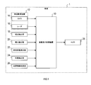
- FIG. 1 is a block diagram illustrating a configuration of an in-vehicle display system according to the embodiment.
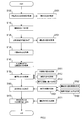
- FIG. 2 is a flowchart showing the procedure of the display control process.
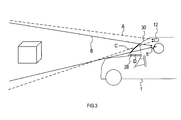
- FIG. 3 is an explanatory diagram illustrating the relationship among the field of view of the periphery monitoring device, the field of view of the driver, the HUD projection surface, and the HUD display surface.
- in-vehicle display system The configuration of the in-vehicle display system according to the embodiment will be described with reference to FIG.
- This in-vehicle display system is a system that presents information to a driver using a HUD, and is mounted on the vehicle 1.
- the in-vehicle display system includes an in-vehicle display control device 10 and each unit connected to the in-vehicle display control device 10.
- the in-vehicle display control device 10 includes a periphery monitoring device 12, a viewpoint detection unit 18, a visual acuity detection unit 20, a vehicle behavior detection unit 22, a position detection unit 24, a map information acquisition unit 26, and a head-up display projector (hereinafter referred to as a HUD projector). ) 28 is connected.
- a HUD projector head-up display projector
- the in-vehicle display control device 10 is an information processing device mainly configured by a semiconductor memory (not shown) such as a CPU, RAM, ROM, flash memory, and an input / output interface.
- the vehicle-mounted display control device 10 forms a display image with a virtual image in the driver's front field of view by the HUD projector 28, thereby providing information on the actual scenery seen by the driver through the windshield provided in front of the driver's seat of the vehicle 1. Overlapping display.
- the in-vehicle display control device 10 is embodied by, for example, a microcontroller or the like in which functions as a computer system are integrated.
- the function of the in-vehicle display control device 10 is realized by the CPU executing a program stored in a substantial storage medium such as a ROM or a semiconductor memory.
- the number of microcontrollers constituting the in-vehicle display control device 10 may be one or more.
- the method for realizing the function of the in-vehicle display control device 10 is not limited to software, and some or all of the elements may be realized using hardware in which a logic circuit, an analog circuit, or the like is combined.
- the periphery monitoring device 12 is an optical or electromagnetic sensor for recognizing the scenery in front of the vehicle 1.
- the periphery monitoring device 12 includes, for example, a camera 14 and a radar 16.
- the camera 14 captures the front area of the vehicle 1 that can be seen through the windshield and outputs data of the captured image to the in-vehicle display control device 10.
- the radar 16 transmits radio waves and laser light toward a front area common to the imaging range of the camera 14 and receives the reflected waves to detect the presence / absence of the object and the distance to the object.
- an objective sensor such as an infrared sensor or an ultrasonic sensor may be used as the periphery monitoring device 12.
- the viewpoint detection unit 18 is a sensor having a function of detecting the position of the driver's eyes.
- a camera system having a function of measuring the coordinates of the driver's eye position in the viewpoint vehicle coordinate system can be applied.
- the camera system detects the coordinates of the position of the driver's eye in the vehicle coordinate system by performing image processing on the image of the driver's eye captured by the infrared camera.
- the visual acuity detection unit 20 is a device that detects the state of visual acuity of the driver.
- the visual acuity detection unit 20 it is conceivable to implement an autorefractometer function in cooperation with a known driver status monitor that recognizes a driver's face image using an infrared camera and a computer.
- the autorefractometer is a well-known measuring device that applies infrared light to a subject's eye and automatically analyzes and measures the refractive state of the eye and the presence and degree of myopia, hyperopia, astigmatism, and the like.
- the vehicle behavior detection unit 22 is a sensor for detecting a physical quantity representing the behavior of the vehicle 1.
- the vehicle behavior detection unit 22 includes a gyroscope, a suspension stroke sensor, a vehicle height sensor, a wheel speed sensor, an acceleration sensor, and the like.
- the position detection unit 24 is for detecting the current location of the vehicle 1 based on detection results by a GPS receiver, a gyroscope, a vehicle speed sensor, and the like.
- the map information acquisition unit 26 acquires terrain data including information representing the terrain, road shape, and the like in the coordinates of the absolute coordinate system, and outputs the acquired terrain data to the in-vehicle display control device 10.
- the terrain data acquired by the map information acquisition unit 26 may be recorded in a map information storage medium mounted on the vehicle 1 or acquired by communication with an external device. Good.
- the HUD projector 28 is a display device that projects light constituting information to be displayed to the driver onto the windshield and forms a virtual display image in the driver's front field of view.
- a projector having a structure in which a display panel that displays image information to be projected directly faces a windshield as a projection surface can be used as appropriate.
- a projector having a structure for projecting image information from the display panel via an optical system including a mirror, a lens, and the like can be used as appropriate.
- the in-vehicle display control device 10 controls the position where the display image is projected based on the position of the object recognized by the periphery monitoring device 12 and the position of the driver's eyes. Specifically, the in-vehicle display control device 10 projects the display image so that the display image of the HUD is superimposed on a specific object in the driver's field of view.
- the in-vehicle display control device 10 is configured to perform control for appropriately displaying the HUD display image with respect to the following factors (1) to (7).
- the in-vehicle display control device 10 acquires three-dimensional information of the foreground from the viewpoint position of the periphery monitoring device 12. Specifically, as illustrated in FIG. 3, the in-vehicle display control device 10 uses a visual field space A that is a visual field based on the viewpoint position (that is, the installation position) of the periphery monitoring device 12 in the absolute coordinate system. Get the coordinates of a 3D object.
- the in-vehicle display control device 10 calculates coordinates in the visual field A based on the camera image information and / or radar detection information acquired by the periphery monitoring device 12.
- the information acquired by the periphery monitoring device 12 in a state where the pitch, roll, and yaw are not generated, the ground height of the periphery monitoring device 12, and Coordinates in the visual field space A are calculated using known parameters representing the mounting angle and the like. Even if the pitch of the vehicle 1 is changing, if the frequency of the fluctuation is not more than the specified position, it is assumed that no pitch fluctuation has occurred, and the coordinates are calculated by the first method. And
- the in-vehicle display control device 10 calculates the coordinates in the visual field space A based on the topographic data around the current location acquired by the map information acquisition unit 26.
- This terrain data presupposes that objects such as terrain and roads are recorded in the coordinates of the absolute coordinate system.
- the in-vehicle display control device 10 represents the coordinates represented by the acquired terrain data, the coordinates of the current location of the vehicle 1 detected by the position detection unit 24, the ground height and the mounting angle of the periphery monitoring device 12, and the like. Coordinates in the visual field space A are calculated using known parameters.
- the first method is basically applied.
- the first method considering that a moving object can be an object to be observed, the coordinates of the time when the change of pitch, roll, yaw, etc. occurs and the object is not the object of observation are the past observed. It is assumed that the prediction is made from the coordinates of a plurality of times.
- the in-vehicle display control device 10 analyzes the environmental properties of the information acquired by the periphery monitoring device 12 in S100. Specifically, the in-vehicle display control device 10 performs brightness and color of ambient light, weather (for example, rain / snow), a color of a superimposed object (for example, a color of a vehicle), by image processing on image information of the camera. And the visibility of the superimposed object is recognized. Note that S101 is processing related to the countermeasure to the above-mentioned “(3) Factors related to compatibility between HUD display image and environmental properties”.
- the in-vehicle display control device 10 specifies the superimposed shape A1 based on the three-dimensional information acquired in S100.
- the superimposed shape A1 is the position and shape in the visual field space A of the display image to be displayed superimposed on a specific superimposed object.
- the in-vehicle display control device 10 detects specific superimposed objects such as lane markings, vehicles ahead, and road signs marked on the road from the information on the foreground landscape acquired by the surrounding monitoring device 12. To detect. Then, the position and shape of the display image in the coordinate system of the visual field A are superimposed so that the display image corresponding to the detected superimposition object overlaps the position of the superimposition object as viewed from the viewpoint of the periphery monitoring device 12. It is specified as A1.
- the in-vehicle display control device 10 acquires the eye position as the driver's viewpoint position based on the information acquired by the viewpoint detection unit 18. Specifically, the in-vehicle display control device 10 obtains the driver's viewpoint position as coordinates in a relative coordinate system based on, for example, the mounting position of the infrared camera constituting the viewpoint detection unit 18 or a predetermined position in the vehicle 1. To do.
- the vehicle-mounted display control device 10 acquires information representing the driver's visual acuity based on the detection result by the visual acuity detection unit 20. Specifically, the in-vehicle display control device 10 acquires the presence / absence and degree of myopia, hyperopia, astigmatism, and the eye refraction state as information representing the driver's visual acuity.
- S121 is processing related to the countermeasure to the above-mentioned “(5) Factors related to the physical ability of the driver”. If the response to changes in visual acuity that changes from moment to moment is omitted, the processing of S121 is not required to be performed periodically, and may be configured to be performed only once. Further, instead of actually measuring the visual acuity by the visual acuity detection unit 20, information on the visual acuity of the driver registered in advance may be read and acquired.
- the in-vehicle display control device 10 acquires the superimposed shape A2 corresponding to the driver's visual field B for the superimposed shape A1 specified in S110.
- the visual field B is a visual field based on the start position E of the driver as illustrated in FIG.
- the in-vehicle display control device 10 converts the coordinates of the superimposed shape A1 specified in S110 into a coordinate system based on the viewpoint position of the driver acquired in S120, thereby superimposing the shape A2. Is calculated.
- the superimposed shape A2 represents the position and shape of the display image in the visual field space B.
- a known view conversion method may be used.
- View conversion is a method for expressing a figure viewed from the position of the viewpoint for viewing the figure by moving it to another place in the three-dimensional space.
- the view conversion is a coordinate conversion that moves a figure to a coordinate system (that is, a viewpoint coordinate system) viewed from the position and direction of the viewpoint.
- this is a combination of coordinate transformation that translates the position of the figure in accordance with the coordinates of the viewpoint using the parallel transformation matrix and coordinate transformation that rotates the figure toward the viewpoint using the rotation transformation matrix.
- the superimposed shape A2 is specified so that the display image of the HUD is superimposed on the superimposed object as viewed from the driver's viewpoint.
- the in-vehicle display control device 10 acquires the position and shape of the display frame in the projection plane space C.
- the display frame is a frame that represents a predetermined range in which a display image can be displayed in accordance with the displacement of the superimposed object.
- the display frame is drawn so as to surround the display image.
- the projection plane space C is a coordinate system assigned to a range in which video light output from the HUD projector 28 is projected on the windshield 30 of the vehicle 1.
- the in-vehicle display control device 10 acquires a superimposed shape A3 corresponding to the projection plane space C for the superimposed shape A2 acquired in S130. Specifically, the in-vehicle display control device 10 converts the coordinates of the superimposed shape A2 into a two-dimensional coordinate system assigned on the windshield along a projection line connecting the viewpoint position of the driver and the superimposed shape A2. . In this way, the in-vehicle display control device 10 calculates the superimposed shape A3 that represents the position and shape of the display image in the projection plane space C.
- Perspective projection is a method for drawing on a two-dimensional plane as if a three-dimensional object was viewed. That is, in perspective projection, the apparent size of an object is inversely proportional to the distance. Specifically, if the viewpoint is the origin and the line of sight is in the negative direction on the z-axis perpendicular to the xy plane, the point at the position (x, y, z) is Projected to the position ( ⁇ Ax / z, ⁇ Ay / z) in the forward direction at the position.
- the in-vehicle display control device 10 is configured to correct the display mode for the superimposed shape A3 by executing the processes of S151, S152, and S153 described below.
- the in-vehicle display control device 10 reflects the distortion of the superimposed object on the display mode of the superimposed shape A3. Note that S151 is processing related to the countermeasure to the above-mentioned “(2) Factors related to variation in superimposed objects”. Specifically:
- a HUD display image is superimposed and displayed on a dividing line that divides a road lane.
- the marking lines on the road are drawn so that there is no sudden change using straight lines, clothoid curves, etc., in order to prevent sudden changes in the behavior of vehicles traveling along the driving lane. It is common.
- the display image of the HUD displayed superimposed on such a dividing line is generally expressed by converting a predetermined figure made of a straight line, a clothoid curve, etc. into a shape that matches the driver's viewpoint. is there.
- the road surface on which the marking line is marked is not necessarily a clean plane and may be uneven or distorted. In such a case, there is a possibility that a position or shape shift may occur between the actual landscape and the HUD display image. Therefore, the in-vehicle display control device 10 recognizes the shape of the ground surface using a radar, a camera, an ultrasonic sensor, an infrared sensor, or the like. If the recognized ground surface has a distortion or variation in shape that exceeds an allowable value, the superimposed shape A3 to be superimposed on the ground surface is deformed in accordance with the ground surface distortion or variation. By doing so, even when there is distortion or variation on the ground surface, the display of the HUD adapted to the actual landscape is continued.
- the vehicle-mounted display control device 10 uses a point where a line from the driver's viewpoint position in the vehicle traveling direction intersects the horizon as a reference point, and gradually increases the upper limit of distortion according to the distance from this reference point. Increase By doing so, it is possible to accurately transmit HUD information in the vicinity of the center of the driver's visual field, and to reduce the deviation between the actual scenery and the HUD display image in the vicinity of the driver's visual field.
- the in-vehicle display control device 10 reflects the environmental properties in the display mode of the superimposed shape A3. Note that S152 is processing related to countermeasures for the above-mentioned “(4) Factors related to compatibility between HUD display image and environmental properties”. Specifically:
- the in-vehicle display control device 10 corrects the display mode of the superimposed shape A3 according to the analysis result of the environmental information in S101. Specifically, the in-vehicle display control device 10 determines the color of the superimposition object, and emphasizes the contrast by changing the color of the HUD display image to a color different from that of the superimposition object. For example, if the superimposed object is a white vehicle, the in-vehicle display control device 10 changes the color of the HUD display image to yellow. Moreover, when superimposing the information showing a warning with respect to a yellow vehicle, the vehicle-mounted display control apparatus 10 does not use yellow for the display image of HUD, but uses other colors, such as a yellow complementary color.
- the in-vehicle display control device 10 determines the color of the ambient light and the weather, and adjusts the color of the HUD display image according to the environment. For example, during snowfall, the in-vehicle display control device 10 changes the original white display to another color. Further, when the ambient light looks red due to sunset or the like, the in-vehicle display control device 10 creates a real feeling by adding redness to the display image of the HUD.
- the in-vehicle display control device 10 is configured to perform a display simulating the shape of the superimposed object itself from the display image of the HUD when it is determined that the visibility of the superimposed object is poor from the analysis result of the environmental information. May be. By doing in this way, the visibility of a superposition target object can be supplemented. Specifically, in a situation where visibility is poor due to rain or fog, when the HUD is superimposed on the assumption that there is a lane marking, the vehicle-mounted display control device 10 displays a display that simulates the lane itself. It is possible to do it. By doing in this way, the effective augmented reality by HUD is realizable without being influenced as much as possible by the quality of a visual field.
- S153 the in-vehicle display control device 10 performs a countermeasure regarding the moving expression of the display image of the HUD. Note that S153 is processing related to the above-mentioned “(6) Consideration for imperfection of countermeasures”. Specifically:
- the in-vehicle display control device 10 performs the entire display control process in a period that can be realized.
- the in-vehicle display control device 10 adds an afterimage expression when moving the display image of the HUD. By doing so, it is possible to make the driver perceive the movement of the display image of the HUD as a smooth movement, and the effect of reducing the burden on the eyes of the driver can be expected.
- the in-vehicle display control device 10 sets a margin part that is a room for the display image not being completely visible in the outer peripheral part of the displayable area of the HUD. And the vehicle-mounted display control apparatus 10 produces
- a determination means for detecting a delay is provided in the in-vehicle display control device 10. If it is detected that a delay occurs, the in-vehicle display control device 10 does not update the display itself at that time.
- the in-vehicle display control device 10 acquires the display shape C4 corresponding to the display surface space D of the HUD projector 28 for the superimposed shape A3 acquired in S150.
- the display surface space D is a two-dimensional coordinate system assigned to the image display area in the display panel of the HUD projector 28, as illustrated in FIG.
- the in-vehicle display control apparatus 10 converts the two-dimensional coordinates of the superimposed shape A3 into the two-dimensional display surface space D according to the characteristics such as the curvature of the projection surface space C and the refractive index of the optical path of the HUD projector 28. Convert coordinates to coordinate system.
- the in-vehicle display control device 10 calculates the display shape C4 representing the position and shape of the display image in the display surface space D. This coordinate transformation is calculated using, for example, a transformation matrix between two planes of the projection plane space C and the image display area.
- the in-vehicle display control device 10 is configured to correct the display mode for the display shape C4 by executing the processes of S161, S162, and S163 described below.
- the in-vehicle display control device 10 reflects the change in the behavior of the vehicle 1 in the display mode of the display shape C4. Note that S161 is processing related to the countermeasure to the above-mentioned “(1) Factors related to vehicle behavior”. Specifically:
- the in-vehicle display control device 10 detects a vehicle rotation angle such as a pitch angle, a roll angle, and a yaw angle of the vehicle 1 based on information acquired by the vehicle behavior detection unit 22, the camera 14, and the radar 16. And the relative position with respect to the real scenery of the vehicle 1 is estimated using together the detected vehicle rotation angle and detection results, such as a wheel speed sensor and an acceleration sensor. And the vehicle-mounted display control apparatus 10 estimates the deviation
- a vehicle rotation angle such as a pitch angle, a roll angle, and a yaw angle of the vehicle 1 based on information acquired by the vehicle behavior detection unit 22, the camera 14, and the radar 16.
- the relative position with respect to the real scenery of the vehicle 1 is estimated using together the
- the in-vehicle display control device 10 reflects the driver's adaptation factor for the processing in S161.
- S162 is processing related to the countermeasure to the above-mentioned “(3) Factors relating to human adaptation to vehicle behavior”. Specifically:
- the in-vehicle display control device 10 analyzes the time transition of the pitch angle as a frequency component, and performs a high-pass filter process corresponding to a predetermined lower limit frequency region. Thereby, the in-vehicle display control device 10 excludes the correction of the display shape C4 from a gentle pitch change lower than the frequency range of the high-pass filter. In this way, the driver's adaptation to a gradual pitch change can be reflected in the display mode of the HUD display image.
- the in-vehicle display control device 10 implements measures for reducing the processing load for the processing in S161.
- S163 is processing related to the above-mentioned “(7) Consideration for reduction in processing load”. Specifically:
- the in-vehicle display control device 10 is used to change behavior in a frequency range that exceeds a limit value (for example, about 30 to 50 Hz) of a frequency at which humans can recognize blinking. Does not correct the display shape C4.
- a limit value for example, about 30 to 50 Hz
- the in-vehicle display control device 10 analyzes temporal transitions of the vehicle posture such as the pitch angle, the roll angle, and the yaw angle as frequency components, and performs a low-pass filter process corresponding to a predetermined upper limit frequency range. Thereby, the vehicle-mounted display control apparatus 10 does not correct the display shape C4 for a behavior change in a frequency range that cannot be recognized by a human. In this way, the processing load can be reduced by omitting the processing for an unnecessary behavior change that cannot be recognized by a human.
- the in-vehicle display control device 10 may be configured to stop the display mode correction or the HUD display itself. This is effective from the viewpoint of reducing processing load and power consumption.
- the in-vehicle display control device 10 outputs the display shape C4 acquired in S160 to the display panel of the HUD projector 28. Thereby, the display shape C4 is projected from the HUD projector 28 onto the windshield 30, and a display image recognized in front of the driver's field of view is formed.
- the in-vehicle display control device 10 is configured to correct the display mode for the display shape C4 by executing the process of S171 described below.
- the vehicle-mounted display control device 10 reflects the measurement result of the driver's visual acuity in the display mode of the display shape C4. Note that S171 is processing related to the countermeasure to the above-mentioned “(5) Factors related to the physical ability of the driver”. Specifically:
- the vehicle-mounted display control device 10 is based on the information on the driver's visual acuity acquired in S121, and the display image of the HUD from the driver according to the quality of visual acuity and the degree of refractive abnormality such as myopia, hyperopia, astigmatism And the brightness of the HUD display image are adjusted. By doing in this way, it is possible to cope with individual differences in visual acuity for each driver and situations where the visual acuity changes from moment to moment due to fatigue or the like in the same driver.
- the vehicle-mounted display system has the following effects.
- various factors that may cause a deviation or discomfort between the display image of the HUD and the actual scenery depending on the situation such as the behavior of the vehicle, the nature of the external environment, the physical ability of the driver, etc.
- the display mode of the HUD display image can be adjusted. This can reduce display image incompatibility and discomfort in the HUD.
- the processing of S100 executed by the in-vehicle display control device 10 corresponds to processing as a spatial information acquisition unit.
- the process of S120 executed by the in-vehicle display control device 10 corresponds to the process as the viewpoint information acquisition unit.
- the processing of S110, S130, S150 to S153, S160 to S163, and S171 executed by the in-vehicle display control device 10 corresponds to processing as a display control unit.
- the process of S170 executed by the in-vehicle display control device 10 corresponds to a process as an output unit.
- the processing of S161 executed by the in-vehicle display control device 10 corresponds to behavior related control.
- the processing of S101, S151, and S152 executed by the in-vehicle display control device 10 corresponds to environment-related control.
- the processing of S121 and S171 executed by the in-vehicle display control device 10 corresponds to physical ability related control.
Landscapes
- Engineering & Computer Science (AREA)
- Physics & Mathematics (AREA)
- Mechanical Engineering (AREA)
- General Physics & Mathematics (AREA)
- Combustion & Propulsion (AREA)
- Chemical & Material Sciences (AREA)
- Transportation (AREA)
- General Engineering & Computer Science (AREA)
- Theoretical Computer Science (AREA)
- Optics & Photonics (AREA)
- Human Computer Interaction (AREA)
- Instrument Panels (AREA)
- Controls And Circuits For Display Device (AREA)
- Fittings On The Vehicle Exterior For Carrying Loads, And Devices For Holding Or Mounting Articles (AREA)
Abstract
L'invention concerne un dispositif (10) d'affichage embarqué qui commande un affichage tête haute (28) pour afficher des informations devant être présentées au conducteur d'un véhicule (1) en tant qu'image d'affichage sous la forme d'une image virtuelle devant être vue dans le champ de vision avant du conducteur. Le dispositif d'affichage embarqué est configuré de façon à exécuter au moins une commande parmi une commande liée au comportement, une commande liée à l'environnement et une commande liée à la capacité physique. La commande liée au comportement se réfère à une commande de réglage du mode d'affichage de l'image affichée par l'affichage tête haute sur la base d'informations indiquant le comportement du véhicule. La commande liée à l'environnement se réfère à une commande de réglage du mode d'affichage de l'image affichée par l'affichage tête haute sur la base d'informations indiquant les attributs d'un environnement externe. La commande liée à la capacité physique se réfère à une commande de réglage du mode d'affichage de l'image affichée par l'affichage tête haute sur la base d'informations indiquant la capacité physique du conducteur.
Priority Applications (2)
| Application Number | Priority Date | Filing Date | Title |
|---|---|---|---|
| DE112017005111.8T DE112017005111T5 (de) | 2016-10-07 | 2017-10-06 | Bordanzeigesteuervorrichtung |
| US16/375,898 US11194154B2 (en) | 2016-10-07 | 2019-04-05 | Onboard display control apparatus |
Applications Claiming Priority (2)
| Application Number | Priority Date | Filing Date | Title |
|---|---|---|---|
| JP2016-199185 | 2016-10-07 | ||
| JP2016199185A JP6756228B2 (ja) | 2016-10-07 | 2016-10-07 | 車載表示制御装置 |
Related Child Applications (1)
| Application Number | Title | Priority Date | Filing Date |
|---|---|---|---|
| US16/375,898 Continuation US11194154B2 (en) | 2016-10-07 | 2019-04-05 | Onboard display control apparatus |
Publications (1)
| Publication Number | Publication Date |
|---|---|
| WO2018066695A1 true WO2018066695A1 (fr) | 2018-04-12 |
Family
ID=61831171
Family Applications (1)
| Application Number | Title | Priority Date | Filing Date |
|---|---|---|---|
| PCT/JP2017/036483 WO2018066695A1 (fr) | 2016-10-07 | 2017-10-06 | Dispositif de commande d'affichage embarqué |
Country Status (4)
| Country | Link |
|---|---|
| US (1) | US11194154B2 (fr) |
| JP (1) | JP6756228B2 (fr) |
| DE (1) | DE112017005111T5 (fr) |
| WO (1) | WO2018066695A1 (fr) |
Cited By (1)
| Publication number | Priority date | Publication date | Assignee | Title |
|---|---|---|---|---|
| WO2021049141A1 (fr) * | 2019-09-13 | 2021-03-18 | マレリ株式会社 | Dispositif d'affichage et procédé d'affichage |
Families Citing this family (15)
| Publication number | Priority date | Publication date | Assignee | Title |
|---|---|---|---|---|
| US11119315B2 (en) * | 2015-10-15 | 2021-09-14 | Maxell, Ltd. | Information display apparatus |
| FR3075986B1 (fr) * | 2017-12-21 | 2022-07-15 | Thales Sa | Procede d'harmonisation duale d'un sous-systeme de detection de posture ddp integre dans un systeme de visualisation tete haute porte |
| CN108499104B (zh) * | 2018-04-17 | 2022-04-15 | 腾讯科技(深圳)有限公司 | 虚拟场景中的方位显示方法、装置、电子装置及介质 |
| KR102116783B1 (ko) * | 2018-10-10 | 2020-05-29 | 네이버랩스 주식회사 | 영상을 지면에 위치시켜 운전자의 시점에 증강현실을 구현하는 3차원 증강현실 헤드업 디스플레이 |
| WO2020075911A1 (fr) | 2018-10-10 | 2020-04-16 | 네이버랩스 주식회사 | Dispositif d'affichage tête haute tridimensionnel à réalité augmentée permettant de mettre en œuvre une réalité augmentée dans le point de vue du conducteur en plaçant une image sur le sol |
| JP2020069824A (ja) * | 2018-10-29 | 2020-05-07 | 株式会社デンソー | 車両用表示装置 |
| CN109889807A (zh) * | 2019-03-14 | 2019-06-14 | 百度在线网络技术(北京)有限公司 | 车载投射调节方法、装置、设备和存储介质 |
| EP3968630A4 (fr) * | 2019-04-11 | 2022-05-18 | Panasonic Intellectual Property Management Co., Ltd. | Système de détection de changement de gradient, système d'affichage l'utilisant, et programme pour le déplacement d'un corps |
| JP7063856B2 (ja) * | 2019-07-30 | 2022-05-09 | 株式会社Soken | 表示制御装置 |
| JP7441628B2 (ja) * | 2019-10-08 | 2024-03-01 | 株式会社Subaru | 車両のヘッドアップディスプレイシステム |
| CN113129224B (zh) | 2019-12-31 | 2023-11-28 | 精工爱普生株式会社 | 显示系统、电子设备、移动体和显示方法 |
| EP3848781B1 (fr) | 2019-12-31 | 2023-05-10 | Seiko Epson Corporation | Dispositif de circuit, appareil électronique et corps mobile |
| US11623653B2 (en) | 2020-01-23 | 2023-04-11 | Toyota Motor Engineering & Manufacturing North America, Inc. | Augmented reality assisted traffic infrastructure visualization |
| WO2021251115A1 (fr) | 2020-06-08 | 2021-12-16 | パナソニックIpマネジメント株式会社 | Systéme d'affichage |
| CN115167743B (zh) * | 2022-06-10 | 2024-04-02 | 东风汽车集团股份有限公司 | 一种车载智能屏幕调节方法、系统及电子设备 |
Citations (8)
| Publication number | Priority date | Publication date | Assignee | Title |
|---|---|---|---|---|
| JP2002159011A (ja) * | 2000-11-20 | 2002-05-31 | Sharp Corp | 画像復号装置 |
| JP2005207777A (ja) * | 2004-01-20 | 2005-08-04 | Mazda Motor Corp | 車両用画像表示装置、車両用画像表示方法及び車両用画像表示プログラム |
| JP2005322143A (ja) * | 2004-05-11 | 2005-11-17 | Namco Ltd | プログラム、情報記憶媒体及び画像生成システム |
| JP2009210432A (ja) * | 2008-03-04 | 2009-09-17 | Alpine Electronics Inc | 運転支援装置 |
| JP2010156608A (ja) * | 2008-12-26 | 2010-07-15 | Toshiba Corp | 車載用表示システム及び表示方法 |
| JP2013047021A (ja) * | 2011-08-28 | 2013-03-07 | Nippon Seiki Co Ltd | 車両用ヘッドアップディスプレイ装置 |
| JP2015080988A (ja) * | 2013-10-22 | 2015-04-27 | 日本精機株式会社 | 車両情報投影システム及び投影装置 |
| JP2017094882A (ja) * | 2015-11-23 | 2017-06-01 | アイシン・エィ・ダブリュ株式会社 | 虚像生成システム、虚像生成方法及びコンピュータプログラム |
Family Cites Families (12)
| Publication number | Priority date | Publication date | Assignee | Title |
|---|---|---|---|---|
| JPS60131328A (ja) * | 1983-12-19 | 1985-07-13 | Nissan Motor Co Ltd | 車両用表示装置 |
| JPH07257228A (ja) | 1994-03-18 | 1995-10-09 | Nissan Motor Co Ltd | 車両用表示装置 |
| JP2007318324A (ja) * | 2006-05-24 | 2007-12-06 | Toyota Motor Corp | 画像表示装置 |
| JP2011007562A (ja) * | 2009-06-24 | 2011-01-13 | Toshiba Alpine Automotive Technology Corp | 車両用ナビゲーション装置及びナビゲーション方法 |
| JP5286243B2 (ja) * | 2009-12-18 | 2013-09-11 | 矢崎総業株式会社 | ヘッドアップディスプレイ装置 |
| JP2013148599A (ja) * | 2010-04-27 | 2013-08-01 | Panasonic Electric Works Co Ltd | 表示装置 |
| JP5685499B2 (ja) * | 2010-07-09 | 2015-03-18 | 株式会社東芝 | 表示装置、画像データ生成装置、画像データ生成プログラム及び表示方法 |
| JP2013154712A (ja) * | 2012-01-27 | 2013-08-15 | Denso Corp | 表示制御装置 |
| JP2013237320A (ja) * | 2012-05-14 | 2013-11-28 | Toshiba Alpine Automotive Technology Corp | 違和感軽減表示装置およびその表示制御方法 |
| CN105682973B (zh) * | 2013-10-22 | 2018-06-19 | 日本精机株式会社 | 车辆信息投影系统和投影装置 |
| JP2016048344A (ja) * | 2014-08-28 | 2016-04-07 | パナソニックIpマネジメント株式会社 | ヘッドアップディスプレイシステム、虚像表示装置 |
| JP6521302B2 (ja) | 2015-04-13 | 2019-05-29 | 株式会社ジェイテクト | 車両用操舵装置 |
-
2016
- 2016-10-07 JP JP2016199185A patent/JP6756228B2/ja active Active
-
2017
- 2017-10-06 DE DE112017005111.8T patent/DE112017005111T5/de not_active Ceased
- 2017-10-06 WO PCT/JP2017/036483 patent/WO2018066695A1/fr active Application Filing
-
2019
- 2019-04-05 US US16/375,898 patent/US11194154B2/en active Active
Patent Citations (8)
| Publication number | Priority date | Publication date | Assignee | Title |
|---|---|---|---|---|
| JP2002159011A (ja) * | 2000-11-20 | 2002-05-31 | Sharp Corp | 画像復号装置 |
| JP2005207777A (ja) * | 2004-01-20 | 2005-08-04 | Mazda Motor Corp | 車両用画像表示装置、車両用画像表示方法及び車両用画像表示プログラム |
| JP2005322143A (ja) * | 2004-05-11 | 2005-11-17 | Namco Ltd | プログラム、情報記憶媒体及び画像生成システム |
| JP2009210432A (ja) * | 2008-03-04 | 2009-09-17 | Alpine Electronics Inc | 運転支援装置 |
| JP2010156608A (ja) * | 2008-12-26 | 2010-07-15 | Toshiba Corp | 車載用表示システム及び表示方法 |
| JP2013047021A (ja) * | 2011-08-28 | 2013-03-07 | Nippon Seiki Co Ltd | 車両用ヘッドアップディスプレイ装置 |
| JP2015080988A (ja) * | 2013-10-22 | 2015-04-27 | 日本精機株式会社 | 車両情報投影システム及び投影装置 |
| JP2017094882A (ja) * | 2015-11-23 | 2017-06-01 | アイシン・エィ・ダブリュ株式会社 | 虚像生成システム、虚像生成方法及びコンピュータプログラム |
Cited By (3)
| Publication number | Priority date | Publication date | Assignee | Title |
|---|---|---|---|---|
| WO2021049141A1 (fr) * | 2019-09-13 | 2021-03-18 | マレリ株式会社 | Dispositif d'affichage et procédé d'affichage |
| JP2021043901A (ja) * | 2019-09-13 | 2021-03-18 | マレリ株式会社 | 表示装置及び表示方法 |
| US11758102B2 (en) | 2019-09-13 | 2023-09-12 | Marelli Corporation | Display device and display method |
Also Published As
| Publication number | Publication date |
|---|---|
| US20190235241A1 (en) | 2019-08-01 |
| JP6756228B2 (ja) | 2020-09-16 |
| US11194154B2 (en) | 2021-12-07 |
| DE112017005111T5 (de) | 2019-07-11 |
| JP2018058544A (ja) | 2018-04-12 |
Similar Documents
| Publication | Publication Date | Title |
|---|---|---|
| WO2018066695A1 (fr) | Dispositif de commande d'affichage embarqué | |
| JP6608146B2 (ja) | ライブ映像を有する仮想透過型インストルメントクラスタ | |
| JP4978721B2 (ja) | 運転支援装置 | |
| US10179588B2 (en) | Autonomous vehicle control system | |
| CN103885573B (zh) | 车用显示系统的自动校正方法及其系统 | |
| JP6559253B2 (ja) | 車両の車両周囲を表示するための方法 | |
| US9463743B2 (en) | Vehicle information display device and vehicle information display method | |
| JP5600256B2 (ja) | 情報表示装置 | |
| Langner et al. | Traffic awareness driver assistance based on stereovision, eye-tracking, and head-up display | |
| US20190241070A1 (en) | Display control device and display control method | |
| JP2016210212A (ja) | 情報提供装置、情報提供方法及び情報提供用制御プログラム | |
| US20190283778A1 (en) | Controlling the operation of a head-up display apparatus | |
| EP3811326A1 (fr) | Système et méthodologies de commande de contenu d'affichage tête haute (hud) | |
| CN114063295A (zh) | 增强现实图像的动态调整 | |
| US20200239018A1 (en) | Method for displaying safety-relevant information on a display device of a vehicle | |
| JP2017056909A (ja) | 車両用画像表示装置 | |
| CN112987053A (zh) | 监测偏航传感器的方法和设备 | |
| CN113767026A (zh) | 用于运行机动车的方法 | |
| JP7126115B2 (ja) | 表示システム、移動体、及び、設計方法 | |
| US11990066B2 (en) | System and method to adjust inclined heads-up display perspective | |
| WO2022230995A1 (fr) | Dispositif de commande d'affichage, dispositif d'affichage tête haute et procédé de commande d'affichage | |
| US20220270527A1 (en) | Display control device | |
| CN111086518B (zh) | 显示方法、装置、车载平视显示设备及存储介质 | |
| JP2019081480A (ja) | ヘッドアップディスプレイ装置 | |
| WO2023184140A1 (fr) | Procédé, appareil et système d'affichage |
Legal Events
| Date | Code | Title | Description |
|---|---|---|---|
| 121 | Ep: the epo has been informed by wipo that ep was designated in this application |
Ref document number: 17858531 Country of ref document: EP Kind code of ref document: A1 |
|
| 122 | Ep: pct application non-entry in european phase |
Ref document number: 17858531 Country of ref document: EP Kind code of ref document: A1 |