WO2018062013A1 - ブレード - Google Patents
ブレード Download PDFInfo
- Publication number
- WO2018062013A1 WO2018062013A1 PCT/JP2017/034214 JP2017034214W WO2018062013A1 WO 2018062013 A1 WO2018062013 A1 WO 2018062013A1 JP 2017034214 W JP2017034214 W JP 2017034214W WO 2018062013 A1 WO2018062013 A1 WO 2018062013A1
- Authority
- WO
- WIPO (PCT)
- Prior art keywords
- blade
- support film
- thermosetting polyurethane
- polyurethane layer
- thickness
- Prior art date
- Legal status (The legal status is an assumption and is not a legal conclusion. Google has not performed a legal analysis and makes no representation as to the accuracy of the status listed.)
- Ceased
Links
Images

Classifications
-
- G—PHYSICS
- G03—PHOTOGRAPHY; CINEMATOGRAPHY; ANALOGOUS TECHNIQUES USING WAVES OTHER THAN OPTICAL WAVES; ELECTROGRAPHY; HOLOGRAPHY
- G03G—ELECTROGRAPHY; ELECTROPHOTOGRAPHY; MAGNETOGRAPHY
- G03G15/00—Apparatus for electrographic processes using a charge pattern
-
- G—PHYSICS
- G03—PHOTOGRAPHY; CINEMATOGRAPHY; ANALOGOUS TECHNIQUES USING WAVES OTHER THAN OPTICAL WAVES; ELECTROGRAPHY; HOLOGRAPHY
- G03G—ELECTROGRAPHY; ELECTROPHOTOGRAPHY; MAGNETOGRAPHY
- G03G21/00—Arrangements not provided for by groups G03G13/00 - G03G19/00, e.g. cleaning, elimination of residual charge
Definitions
- the present invention relates to a blade used in an electrophotographic apparatus such as a copying machine, a printer, a facsimile machine, or a multifunction machine of these.
- blades such as a cleaning blade, a developing blade, a conductive blade, a polishing blade, and a coating blade are used.
- a blade generally used has a metal support member and an elastic body made of a thermosetting polyurethane bonded to the support member.
- An elastic body made of thermosetting polyurethane may have a release agent applied to a mold used in the thermosetting process.
- the support member may be attached with mineral oil called punching oil for reducing the frictional resistance used in the pressing process. For this reason, the elastic body and the support member cannot be firmly joined as they are, and often require a degreasing cleaning treatment or the like before joining.
- Patent Document 1 discloses that a ditan acid is used as a mold release agent applied to a mold used when a blade member (elastic body) is molded.
- a cleaning blade excellent in adhesiveness between an elastic body and a support member has been proposed by combining with an adhesive composed of a base compound.
- Patent Document 2 uses a holder (support member) formed from an organic lubricating film steel plate that does not require oil during press processing, and uses a specific material such as polyurethane as an organic lubricating film, thereby A cleaning blade excellent in adhesiveness with a support member has been proposed.
- the pretreatment for joining the elastic body and the supporting member as described above, a special adhesive, and a steel plate are unnecessary.
- An object of the present invention is to provide a novel blade that does not require a metal support member.
- a blade comprising: a support film; and a thermosetting polyurethane layer laminated on the support film.
- the thickness of the support film is 0.02 mm or more and 1 mm or less.
- the blade described in. 3. 1.
- the thermosetting polyurethane has a thickness of 0.1 mm or more and less than 0.5 mm. Or 2.
- the support film is any one of polyethylene terephthalate, polycarbonate, polyimide, ultrahigh molecular weight polyethylene, and fluororesin.
- One or both of the support film and the thermosetting polyurethane layer contain a conductive material. ⁇ 4.
- 1. A polishing layer is provided on the surface of the support film opposite to the thermosetting polyurethane layer. ⁇ 5.
- the thermosetting polyurethane layer contains an abrasive. ⁇ 5.
- a housing 1. a photoreceptor disposed in the casing; To 7.
- a blade according to any one of It is detachable from the main body of the electrophotographic device, A process cartridge, wherein the blade is directly fixed to the casing. 9. 7.
- the thermosetting polyurethane layer of the blade is in contact with the photoreceptor. Process cartridge according to. 10.
- Process cartridge according to. 11 A method of manufacturing a blade having a support film and a thermosetting polyurethane layer laminated on the support film, Pouring the polyurethane composition into the gap between the first and second gap maintaining members fed by a pair of spaced apart rollers; The polyurethane composition is thermoset while being held between the first and second gap maintaining members to form the thermosetting polyurethane layer; One of said 1st and 2nd gap
- thermosetting polyurethane layer A support film obtained by a manufacturing method using one of the first and second gap maintaining members as a support film, and a thermosetting polyurethane layer laminated on the support film, Blade to be.
- the blade of the present invention has a novel configuration completely different from a conventionally used blade having a metal support member and an elastic body made of thermosetting polyurethane joined to the support member. That is, the blade of the present invention has a support film and a thermosetting polyurethane layer. Since the dimensional stability of the blade of the present invention is improved by having a support film having rigidity higher than that of the thermosetting polyurethane, even when there is no metal support member, the blade is uniformly deformed without being deformed. Can contact.
- the blade of the present invention can be pretreated for joining the elastic body and the support member, and can use a special adhesive, a steel plate, or the support member itself, which is very low compared to the conventional blade. Cost.
- the blade of the present invention can be adjusted in strength and elasticity according to the material and thickness of the support film and the thermosetting polyurethane, and can be used as a blade for various applications.
- both the corners on the thermosetting polyurethane layer side and the support film side can be used as edge portions in contact with the photoreceptor.
- thermosetting polyurethane is conventionally used as a material for forming an elastic body for blades, and thus has high reliability.
- the edge on the support film side is the edge part, a material having higher hardness and lower friction than the thermosetting polyurethane is used as the support film, so that it cannot be achieved with the blades using the conventional thermosetting polyurethane as the edge part.
- Possible low friction can be imparted. By reducing the friction of the edges, it is possible to prevent filming (adherence) of toner and external additives to the photoconductor, and to reduce the wear of the photoconductor, thus extending the life of the photoconductor. Can be achieved.
- a blade having an edge portion on the side of the support film, which has high hardness and low friction, can be suitably used for low-melting-point toners that are increasingly used in recent years.
- the blade of the present invention is a laminate of a support film made of a flexible material and a thermosetting polyurethane layer, it can prevent damage due to contact. Therefore, the blade of the present invention does not require a packing material when stored, transported, and the like, and even if packed, the packing can be simplified as compared with the conventional one.
- the blade of the present invention can greatly reduce the space and cost required for storage and transportation.
- a laminate in which a support film / thermosetting polyurethane layer / release film or a second support film is laminated in this order can be continuously produced by a so-called roll-to-roll. it can.
- the blade of the present invention can be manufactured only by cutting this laminate into a predetermined size, and the manufacturing cost of the blade can be greatly reduced.
- the laminated body wound in roll shape is not bulky and is excellent in handleability.
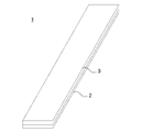
- FIG. 1 shows a schematic view of one embodiment of the blade of the present invention.
- the thickness of each layer does not mean the actual thickness.
- the blade 1 which is one embodiment has a support film 2 and a thermosetting polyurethane layer 3 laminated on the support film 2.
- the blade 1 according to one embodiment includes flexibility and elasticity derived from the thermosetting polyurethane layer 3, and stiffness, dimensional stability, wear resistance, and a low coefficient of friction derived from the support film 2,
- the photosensitive member can be contacted at an appropriate pressure.
- thermosetting polyurethane layer The thermosetting polyurethane layer 3 is obtained by thermosetting a polyurethane composition containing a polyol and a polyisocyanate.
- Polyol Polyols include polyoxyalkylene glycols such as polyethylene glycol, polypropylene glycol and polyoxytetramethylene glycol, or polyether-type polyols of alkylene oxide adducts such as bisphenol A, glycerin ethylene oxide and propylene oxide; adipic acid, By polymerization reaction of dibasic acids such as phthalic anhydride, isophthalic acid, maleic acid and fumaric acid with glycols such as ethylene glycol, propylene glycol, 1,4-butanediol, 1,6-hexanediol and trimethylolpropane Examples thereof include polyester polyols obtained; polycaprolactone diols; polycarbonate diols and the like.
- the blade of the present invention can be used as an edge portion in contact with the photoconductor or the like at both corners on the thermosetting polyurethane layer 3 side and the support film 2 side.
- a polyester type polyol is preferable because it is excellent in flexibility, wear resistance, cost, and the like.
- a polyether type polyol having less environmental dependency of viscoelasticity is preferable.
- Polyisocyanate Polyisocyanates include meta-xylene diisocyanate (XDI), tolylene diisocyanate (TDI), 4,4-diphenylmethane diisocyanate (MDI), hexamethylene diisocyanate (HDI), isophorone diisocyanate (IPDI), 1,4-cyclohexane diisocyanate, hydrogen And diphenylmethane diisocyanate.
- XDI meta-xylene diisocyanate
- TDI tolylene diisocyanate
- MDI 4,4-diphenylmethane diisocyanate
- HDI hexamethylene diisocyanate
- IPDI isophorone diisocyanate
- 1,4-cyclohexane diisocyanate 1,4-cyclohexane diisocyanate
- the equivalent ratio of OH group / NCO group is preferably 0.8 or more and 1.10 or less, more preferably 0.90 or more and 1.05 or less, from the physical properties of the polyurethane to be produced.
- polyurethane compositions include crosslinking agents (chain extenders), surfactants, flame retardants, colorants, fillers, plasticizers, stabilizers, mold release agents, catalysts (reaction promotion)
- An additive such as an agent can be blended.
- a conductive material and an abrasive can be blended.
- chain extender examples include low molecular weight diols such as ethylene glycol, 1,4-butanediol, diethylene glycol, 1,6-hexanediol, and neopentyl glycol, and diamines such as ethylenediamine, hexamethylenediamine, and isophoronediamine. Desirably, a low molecular weight diol is used.
- triols such as trimethylolpropane, triamines such as triethanolamine, glycerin, and these ethylene oxide and propylene oxide adducts can be added as a polyfunctional component as necessary.
- a reaction accelerator such as a general amine compound or an organic tin compound can be used as necessary.
- examples thereof include imidazole derivatives disclosed in Japanese Patent No. 2942183 and paragraphs 0022 to 0023. Specific examples thereof include 2-methylimidazole and 1,2-dimethylimidazole which are highly dependent on reaction temperature in terms of chemical structure.
- the reaction accelerator is preferably used in a range of 0.001 part by weight to 0.5 part by weight with respect to a total of 100 parts by weight of polyol and polyisocyanate, and 0.01 part by weight or more and 0.3 part by weight or less. It is more preferable to use within a range.
- reaction accelerator those having temperature sensitivity or slow-acting property prevent the urethane resin composition mixed with the reaction accelerator from being cured before molding, can extend the pot life, and the demolding time. Is preferable because of shortening. Specifically, 1,8-diazabicyclo (5,4,0) undecene-7-organic acid salt, 1,5-diazabicyclo (4,3,0) nonene-5-organic acid salt called block amine Or a mixture thereof.
- the conventional elastic body for blades made of only thermosetting polyurethane is required to have a thickness of about 2 mm in order to obtain firmness.
- the thickness of the thermosetting polyurethane layer can be less than 0.5 mm. Even if the thickness of the thermosetting polyurethane layer is 0.5 mm or more, the cleaning property is not deteriorated, but the material cost is increased, the amount of heat necessary for uniform thermosetting is increased, and the production cost is also increased.
- the thermosetting polyurethane layer only needs to have a thickness capable of exhibiting sufficient elasticity to be in close contact with the photosensitive member when it is pressed against the photosensitive member and deformed while being laminated on the support film.
- thermosetting polyurethane layer it is preferable to have a thickness of 1 mm or more. If the thickness of the thermosetting polyurethane layer is less than 0.1 mm, the force for pressing the surface of the photoreceptor becomes weak, and the cleaning property is deteriorated. The thicker the thermosetting polyurethane layer, the greater the elasticity. Therefore, it is more preferable to have a thickness of 0.2 mm or more.
- the support film 2 supports the thermosetting polyurethane layer 3.
- the material constituting the support film 2 can be used without particular limitation as long as it is excellent in dimensional stability under the use environment and satisfies the elastic modulus for complementing the strength of stiffness, Ultra high molecular weight polyethylene (UHMWPE), polytetrafluoroethylene (PTFE), tetrafluoroethylene / perfluoroalkyl vinyl ether copolymer (PFA), tetrafluoroethylene / hexafluoropropylene copolymer (FEP), tetrafluoroethylene / ethylene Fluorine resin such as copolymer (ETFE), polyacetal resin (POM), polyamide resin (PA), polyimide (PI), polyetheretherketone (PEEK), polyphenylene sulfide (PPS), polyethylene terephthalate (PET), polycarbonate ( P ), Etc.
- UHMWPE Ultra high molecular weight polyethylene
- PTFE
- ultrahigh molecular weight polyethylene fluororesin, polyetheretherketone, polyimide, polyphenylene sulfide, and polyethylene terephthalate having excellent wear resistance and a small friction coefficient are particularly preferable.
- the ultra-high molecular weight polyethylene is a polyethylene having a weight average molecular weight increased to 1 million or more, and those commercially available from trade names such as Dyneema (Ran DSM) and Spectra (Honeywell) can be used.
- thermosetting polyurethane layer 3 In order to improve the adhesiveness between the support film 2 and the thermosetting polyurethane layer 3, it is preferable to perform a surface treatment on the surface of the support film 2 on the thermosetting polyurethane layer 3 side.
- the surface treatment method is not particularly limited, and examples thereof include flame treatment, corona treatment, plasma treatment, UV treatment, ozone treatment, chemical treatment, and roughening treatment.
- an adhesive layer can be provided on the support film 2 and the thermosetting polyurethane layer 3 can be formed on the adhesive layer.
- the blade 1 can be imparted with antistatic properties.
- the thickness of the support film is preferably 0.02 mm or more and 1 mm or less, more preferably 0.025 mm or more and 0.5 mm or less, and further preferably 0.1 mm or more and 0.2 mm or less. If the thickness of the support film is less than 0.02 mm, the stiffness of the blade is weak and the cleaning performance is lowered. Further, as will be described in detail in the following “Blade manufacturing method”, there is a possibility of deformation during heating in the manufacturing process. If the thickness of the support film is greater than 1 mm, the blade becomes too hard and is difficult to be deformed when pressed against the photoreceptor, and the cleaning property is deteriorated.
- thermosetting polyurethane layer 3 A release film (not shown) can be provided on the surface of the thermosetting polyurethane layer 3 in order to protect the blade 1 as an embodiment from the production until it is installed in the housing of the process cartridge.
- the release film is a film that has been subjected to a release treatment on the surface to be bonded to the thermosetting polyurethane layer 3, and prevents the thermosetting polyurethane layer 3 from being contaminated or adhering to dust.
- the release film is preferably made of a material having a lower hardness than the support film 2 so as not to damage the support film 2 when rubbed.
- the thermosetting polyurethane layer 3 can be directly formed on the release film, as will be described in detail in the following “Blade manufacturing method”.
- thermosetting polyurethane layer 3 is directly formed on the release film by this production method, the thermosetting polyurethane is thermally cured to form a thermosetting polyurethane layer 3, thereby preventing deformation during heating, and releasing the mold.
- the thickness of the release film is preferably 0.018 mm or more and 1 mm or less.
- the blade 1 which is one embodiment has a support film 2 and a thermosetting polyurethane layer 3.
- the two-layer blade 1 can be used as an edge portion in contact with the photoconductor or the like on either side of the thermosetting polyurethane layer 3 side or the support film 2 side.
- Thermosetting polyurethane is a material that has been used as an edge so far and has high reliability.
- the support film uses a material having higher hardness, abrasion resistance, low friction, etc. than thermosetting polyurethane, so that performance that cannot be achieved with blades made of thermosetting polyurethane at the edges so far. It can be demonstrated.
- filming of toner, external additives, and the like on the photosensitive member can be performed by using the corners of the support film 2 made of a material having excellent wear resistance and a low friction coefficient such as ultrahigh molecular weight polyethylene and fluororesin as edge portions. (Fixing) can be prevented, and wear of the photoreceptor can be reduced.
- an edge part uses the angle
- the blade of the present invention is not limited to the two-layer blade according to one embodiment, and may have a layer other than the support film and the thermosetting polyurethane layer.
- a blade composed of a three-layer laminate in which a thermosetting polyurethane layer is sandwiched between a first support film and a second support film. be able to. Since this three-layered blade has a vertically symmetric structure by using the same member for the first support film and the second support film, it is excellent in workability at the time of attachment. Further, as described below, a polishing layer can be provided on the surface of the blade on the support film side.
- the blade 1 according to one embodiment is predetermined without using a metal support member by applying an adhesive, an adhesive tape, a double-sided tape or the like to either the support film 2 side or the thermosetting polyurethane layer 3 side. Can be fixed directly to the position.
- the blade 1 can be fixed with high positional accuracy by providing a concave portion to be fitted to the blade 1 at a place where the blade 1 according to one embodiment is fixed. Since the blade 1 which is one embodiment is excellent in dimensional stability by including the support film 2, the thermosetting polyurethane layer 3 is not easily deformed even when pressure is applied at the time of attachment. The object can be uniformly contacted.
- the blade of the present invention can be directly fixed without using a support member as described above, but a conventional support member can also be used. By joining the blade of the present invention to a conventional support member, the blade of the present invention can be introduced without changing the design of the housing or the support member.
- the blade of the present invention can be used without being limited to various blades such as a cleaning blade, a developing blade, a conductive blade, a polishing blade, and a coating blade.
- the polishing blade if the corner on the thermosetting polyurethane layer side is an edge portion, the polyurethane may contain an abrasive. Further, if the corners on the support film side are edge portions, a polishing layer may be provided on the support film side surface by coating or the like. Examples of the abrasive include cerium oxide, silica, cerium, zirconium, strontium and the like.
- the blade of the present invention can be suitably used for an application mounted inside a process cartridge.
- the process cartridge has a structure in which a plurality of blades such as a photosensitive drum, a charging unit, a developing blade, and a cleaning blade are integrated, and is configured to be detachable from an electrophotographic apparatus.
- a plurality of blades such as a photosensitive drum, a charging unit, a developing blade, and a cleaning blade are integrated, and is configured to be detachable from an electrophotographic apparatus.
- Blade manufacturing method In the blade of the present invention, a long, first and a long composition in which a polyurethane composition containing at least a polyol and a polyisocyanate (or a urethane prepolymer made of these) is sent between a pair of rollers arranged at a distance from each other are provided. Pour into the gap of the second gap maintaining member, and cure the polyurethane composition in a state of being held between the first and second gap maintaining members to form a sheet of a thermosetting polyurethane layer, and then cut. Can be manufactured.
- FIG. 2 shows a schematic diagram of the blade manufacturing method of the present invention.
- a method of manufacturing the blade will be described with reference to FIG.
- a long support film and a long release film are used as the gap maintaining member.
- a polyurethane composition 40a containing at least a polyol and a polyisocyanate (or a urethane prepolymer made of these) is sent through a casting machine 41 between a pair of conveying rollers 43a and 43b that are spaced apart from each other. Pour into the gap between the long support film 42a and the long release film 42b.
- the long support film 42a and the long release film 42b are guided into the heating device 46 while holding the polyurethane composition 40a therebetween.
- the polyurethane composition 40a is thermoset while being held between the long support film 42a and the long release film 42b to form a thermosetting polyurethane sheet 40.
- 44 is a conveying roller for feeding out the long support film 42a and the long release film 42b
- 45 is an auxiliary roller
- 47 is a long support film 42a holding the polyurethane composition 40a. It is a conveyor belt for conveying the long release film 42b in the heating device 46.
- the gap can be maintained at a constant size. it can. Since the polyurethane composition 40a is sandwiched between the long support film 42a and the long release film 42b and is cured while maintaining a constant thickness, the polyurethane composition 40a becomes a sheet 40 having excellent thickness accuracy.
- the sheet-like object 40 having a thickness of 0.1 mm or more, which is difficult to be applied, can be continuously formed with high thickness accuracy.
- the position of the head portion 41a of the casting machine 41 is either one of the conveyance rollers 43a and 43b from the central portion (the central portion of the gap formed by the long support film and the long release films 42a and 42b). It is preferable to be unevenly distributed on the roller side, and the uneven distribution distance is preferably equal to or less than the radius of the transport roller. That is, it is preferable that the position immediately below the head portion 41a of the casting machine 41 is located between the central portion of the pair of transport rollers 43a and 43b and the central axis of one transport roller. Moreover, it is preferable that the shortest distance between the tip of the head portion 41a and the surface of the transport roller is 5 cm or less.
- the head portion 41a By disposing the head portion 41a in this way, the thickness accuracy of the thermosetting polyurethane layer 40 is further improved, and the head portion 41a is not yet poured into the gap between the long support film 42a and the long release film 42b. Air bubbles are not easily mixed into the cured polyurethane composition 40a, and the mixed air bubbles are easily removed.
- the transport rollers 43a and 43b may have only a transport function, but are preferably heating rollers.
- the conveying roller is a heating roller
- the polyurethane composition 40a can be cured immediately after being held in the gap between the long support film 42a and the long release film 42b, and the polyurethane composition 40a is heated by a heating device.
- the thickness can be kept more uniform before being introduced into the sheet 46, and the sheet-like product 40 having more excellent thickness accuracy can be formed.
- the conveying surface temperature when heating the conveying roller is preferably set to 10 to 60 ° C.
- the polyurethane composition 40a may be cured on the transport roller, or air bubbles may enter the sheet-like material 40.
- the heating device 46 is a heating furnace provided with a heater and may be anything that can raise the furnace temperature to the curing temperature of the polyurethane composition 40a. Further, the heating conditions (curing conditions) in the heating device 46 are not particularly limited, and may be appropriately set according to the composition of the polyurethane composition 40a. For example, the conditions are 40 ° C. to 160 ° C., 1 minute to 180 minutes. Just do it.
- the long blade precursor 10 in which the long support film 42a, the thermosetting polyurethane sheet 40, and the long release film 42b are laminated in this order is carried out.
- the long support film 42a is the support film 2
- the sheet-like material 40 is the thermosetting polyurethane layer 3.
- the blade 1 of the present invention in which the thermosetting polyurethane layer 3 is protected with a release film derived from the long release film 42b is obtained.
- the long blade precursor 10 can be continuously produced by a so-called roll-to-roll process, which is excellent in productivity as compared with the conventional method.
- the manufactured long blade precursor 10 may be wound into a roll and shipped, or may be cut and shipped as the blade 1.
- PET having a thickness of 100 ⁇ m treated as a long support film (trade name: Lumirror S10, manufactured by Toray Industries, Inc.) and PET having a thickness of 38 ⁇ m subjected to silicon treatment as a long release film (manufactured by Toray Industries, Inc.).
- a product name: Lumirror S10 manufactured by Toray Industries, Inc.
- thermosetting at 140 ° C. for 1 minute Using a product name: Lumirror S10) and thermosetting at 140 ° C. for 1 minute using the above production method, a long blade precursor having a thermosetting polyurethane layer thickness of 0.3 mm was obtained. .
- This blade precursor was cut into a width of 30 mm and a length of 320 mm, and the release film was peeled off to obtain a blade 1.
- Example 2 A blade 2 was obtained in the same manner as in Example 1, except that corona-treated PET having a thickness of 250 ⁇ m (trade name: Lumirror S10) was used as the support film.
- Example 3 A blade 3 was obtained in the same manner as in Example 1 except that UHMWPE (trade name: No. 440, manufactured by Nitto Denko Corporation) having a corona treatment thickness of 200 ⁇ m was used as the support film.
- Example 4 A blade 4 was obtained in the same manner as in Example 1 except that a corona-treated UHMWPE having a thickness of 500 ⁇ m (manufactured by Nitto Denko Corporation, trade name: No. 440) was used as the support film.
- Example 5" A blade 5 was obtained in the same manner as in Example 1 except that UHMWPE having a thickness of 50 ⁇ m treated with corona (trade name: Ultra Polymer, manufactured by Yodogawa Hutec Co., Ltd.) was used as the support film.
- UHMWPE Ultra Polymer, manufactured by Yodogawa Hutec Co., Ltd.
- Example 6 A blade 6 was obtained in the same manner as in Example 1 except that corona-treated ETFE (trade name: Aflex) manufactured by Asahi Glass Co., Ltd. was used as the support film.
- Example 7 A blade 7 was obtained in the same manner as in Example 1 above, except that corona-treated ETFE (trade name: Aflex) manufactured by Asahi Glass Co., Ltd. was used as the support film.
- Example 8 A blade 8 was obtained in the same manner as in Example 1 except that the thickness of the polyurethane layer was 100 ⁇ m.
- Example 9 A blade 9 was obtained in the same manner as in Example 1 except that the thickness of the polyurethane layer was 480 ⁇ m.
- Example 10 A blade 10 was obtained in the same manner as in Example 1 except that PET having a corona-treated thickness of 480 ⁇ m (trade name: Lumirror H10) was used as the support film.
- Example 11 A blade 11 was obtained in the same manner as in Example 1 except that corona-treated PET with a thickness of 25 ⁇ m (trade name: Lumirror S10) was used as the support film.
- Comparative Example 1 A blade 12 was obtained in the same manner as in Example 1 except that PET having a corona treatment thickness of 16 ⁇ m (Toray, Lumirror FB50) was used as the support film.
- Comparative Example 2 A blade 13 was obtained in the same manner as in Example 1 except that a corona-treated 1.5 mm thick UHMWPE (manufactured by Nitto Denko Corporation, trade name: No. 440) was used as the support film.
- Comparative Example 3 A blade 14 was obtained in the same manner as in Example 1 except that the thickness of the polyurethane layer was 0.05 mm.
- Example 12 A printing running test (30000 sheets) was carried out on the produced blade as a cleaning blade of a commercially available digital color composite machine (manufactured by Ricoh Co., Ltd., MP C2503) using the corners of polyurethane as edges. Further, as Example 12, a printing running test was similarly conducted using the edge of the blade produced in Example 1 on the support film side as an edge portion. The wear of the edge part after the test was confirmed by visual observation or enlarged observation with a microscope or the like, and evaluated according to the following criteria. Further, occurrence of inconvenience due to the blade was visually confirmed on the charging roller and the printed matter after the test. The results are shown in Table 1 below. In each evaluation, “ ⁇ ” is equivalent to a conventional blade using an elastic body made only of polyurethane.
Landscapes
- Physics & Mathematics (AREA)
- General Physics & Mathematics (AREA)
- Cleaning In Electrography (AREA)
- Electrophotography Configuration And Component (AREA)
- Laminated Bodies (AREA)
Abstract
金属製の支持部材が不要である新規なブレードを提供することを課題とする。解決手段として、支持フィルムと、前記支持フィルムに積層された熱硬化性ポリウレタン層とを有するブレードを提供する。
Description
本発明は、複写機、プリンタ、ファクシミリ、これらの複合機等の電子写真装置において用いられるブレードに関する。
複写機、プリンタ等の電子写真装置では、クリーニングブレード、現像ブレード、導電ブレード、研磨ブレード、塗布ブレード等のブレードが用いられている。従来、一般的に用いられているブレードは、金属製の支持部材と、この支持部材に接合された熱硬化性ポリウレタンからなる弾性体を有する。
熱硬化性ポリウレタンからなる弾性体は、熱硬化工程で使用する金型に塗布される離型剤が付着している場合がある。また、支持部材は、プレス工程で使用される摩擦抵抗を軽減するためのパンチングオイルと称される鉱物油が付着している場合がある。そのため、弾性体と支持部材とは、そのままでは強固に接合できず、接合前に脱脂洗浄処理等が必要なことが多い。
弾性体とブレードとを強固に接合するために、例えば、特許文献1には、ブレード部材(弾性体)の成形時に使用する金型に塗布する離型剤としてモンタン酸エステルを使用し、ダイマー酸ベースの化合物からなる接着剤と組み合わせることで、弾性体と支持部材との接着性に優れたクリーニングブレードが提案されている。また、特許文献2には、プレス加工時に油が不要である有機潤滑皮膜鋼板から形成したホルダー(支持部材)を使用し、有機潤滑皮膜としてポリウレタン系等の特定材料を用いることにより、弾性体と支持部材との接着性に優れたクリーニングブレードが提案されている。
弾性体とブレードとを強固に接合するために、例えば、特許文献1には、ブレード部材(弾性体)の成形時に使用する金型に塗布する離型剤としてモンタン酸エステルを使用し、ダイマー酸ベースの化合物からなる接着剤と組み合わせることで、弾性体と支持部材との接着性に優れたクリーニングブレードが提案されている。また、特許文献2には、プレス加工時に油が不要である有機潤滑皮膜鋼板から形成したホルダー(支持部材)を使用し、有機潤滑皮膜としてポリウレタン系等の特定材料を用いることにより、弾性体と支持部材との接着性に優れたクリーニングブレードが提案されている。
ここで、弾性体のみをブレードとして使用することができれば、上記したような弾性体と支持部材とを接合するための前処理や、特殊な接着剤、鋼板が不要である。しかし、弾性体のみでは、ブレードとして使用することが困難である。これは、ポリウレタンは弾性を有するため、取り付け時に応力が加わると変形して感光体ドラム等の対象物に均一に接触せず、ブレードとしての機能を果たせないためである。
本発明は、金属製の支持部材が不要である新規なブレードを提供することを課題とする。
本発明の課題を解決するための手段は以下のとおりである。
1.支持フィルムと、前記支持フィルムに積層された熱硬化性ポリウレタン層とを有することを特徴とするブレード。
2.前記支持フィルムの厚さが、0.02mm以上1mm以下であることを特徴とする1.に記載のブレード。
3.前記熱硬化性ポリウレタンの厚さが、0.1mm以上0.5mm未満であることを特徴とする1.または2.に記載のブレード。
4.前記支持フィルムが、ポリエチレンテレフタレート、ポリカーボネート、ポリイミド、超高分子量ポリエチレン、フッ素樹脂のいずれかであることを特徴とする1.~3.のいずれかに記載のブレード。
5.前記支持フィルムと前記熱硬化性ポリウレタン層のいずれか、または両方が導電材を含有することを特徴とする1.~4.のいずれかに記載のブレード。
6.前記支持フィルムの前記熱硬化性ポリウレタン層とは反対側の面に、研磨層を有することを特徴とする1.~5.のいずれかに記載のブレード。
7.前記熱硬化性ポリウレタン層が、研磨剤を含有することを特徴とする1.~5.のいずれかに記載のブレード。
8.筐体と、
前記筐体内に配置される感光体と1.から7.のいずれかに記載のブレードとを有し、
電子写真装置本体に脱着自在であり、
前記ブレードが、前記筐体に直接固定されていることを特徴とするプロセスカートリッジ。
9.前記ブレードの熱硬化性ポリウレタン層が、前記感光体に接触することを特徴とする8.に記載のプロセスカートリッジ。
10.前記ブレードの支持フィルム、または研磨層のいずれかが、前記感光体に接触することを特徴とする8.に記載のプロセスカートリッジ。
11.支持フィルムと、前記支持フィルムに積層された熱硬化性ポリウレタン層とを有するブレードの製造方法であって、
ポリウレタン組成物を、離間して配置された一対のローラにより送り出される第一および第二の間隙維持部材の間隙に流し込み、
前記ポリウレタン組成物を、前記第一および第二の間隙維持部材の間に保持された状態で熱硬化して前記熱硬化性ポリウレタン層とし、
前記第一および第二の間隙維持部材の一方を前記支持フィルムとすることを特徴とするブレードの製造方法。
12.ポリウレタン組成物を、離間して配置された一対のローラにより送り出される第一および第二の間隙維持部材の間隙に流し込み、
前記ポリウレタン組成物を、前記第一および第二の間隙維持部材の間に保持された状態で熱硬化して熱硬化性ポリウレタン層とし、
前記第一および第二の間隙維持部材の一方を支持フィルムとする製造方法により得られることを特徴とする支持フィルムと、該支持フィルムに積層された熱硬化性ポリウレタン層とを有することを特徴とするブレード。
1.支持フィルムと、前記支持フィルムに積層された熱硬化性ポリウレタン層とを有することを特徴とするブレード。
2.前記支持フィルムの厚さが、0.02mm以上1mm以下であることを特徴とする1.に記載のブレード。
3.前記熱硬化性ポリウレタンの厚さが、0.1mm以上0.5mm未満であることを特徴とする1.または2.に記載のブレード。
4.前記支持フィルムが、ポリエチレンテレフタレート、ポリカーボネート、ポリイミド、超高分子量ポリエチレン、フッ素樹脂のいずれかであることを特徴とする1.~3.のいずれかに記載のブレード。
5.前記支持フィルムと前記熱硬化性ポリウレタン層のいずれか、または両方が導電材を含有することを特徴とする1.~4.のいずれかに記載のブレード。
6.前記支持フィルムの前記熱硬化性ポリウレタン層とは反対側の面に、研磨層を有することを特徴とする1.~5.のいずれかに記載のブレード。
7.前記熱硬化性ポリウレタン層が、研磨剤を含有することを特徴とする1.~5.のいずれかに記載のブレード。
8.筐体と、
前記筐体内に配置される感光体と1.から7.のいずれかに記載のブレードとを有し、
電子写真装置本体に脱着自在であり、
前記ブレードが、前記筐体に直接固定されていることを特徴とするプロセスカートリッジ。
9.前記ブレードの熱硬化性ポリウレタン層が、前記感光体に接触することを特徴とする8.に記載のプロセスカートリッジ。
10.前記ブレードの支持フィルム、または研磨層のいずれかが、前記感光体に接触することを特徴とする8.に記載のプロセスカートリッジ。
11.支持フィルムと、前記支持フィルムに積層された熱硬化性ポリウレタン層とを有するブレードの製造方法であって、
ポリウレタン組成物を、離間して配置された一対のローラにより送り出される第一および第二の間隙維持部材の間隙に流し込み、
前記ポリウレタン組成物を、前記第一および第二の間隙維持部材の間に保持された状態で熱硬化して前記熱硬化性ポリウレタン層とし、
前記第一および第二の間隙維持部材の一方を前記支持フィルムとすることを特徴とするブレードの製造方法。
12.ポリウレタン組成物を、離間して配置された一対のローラにより送り出される第一および第二の間隙維持部材の間隙に流し込み、
前記ポリウレタン組成物を、前記第一および第二の間隙維持部材の間に保持された状態で熱硬化して熱硬化性ポリウレタン層とし、
前記第一および第二の間隙維持部材の一方を支持フィルムとする製造方法により得られることを特徴とする支持フィルムと、該支持フィルムに積層された熱硬化性ポリウレタン層とを有することを特徴とするブレード。
本発明のブレードは、従来使用されている金属製の支持部材と、この支持部材に接合された熱硬化性ポリウレタンかならる弾性体とを有するブレードとは全く異なる新規な構成を有する。すなわち、本発明のブレードは、支持フィルムと熱硬化性ポリウレタン層とを有する。本発明のブレードは、熱硬化性ポリウレタンよりも剛性の高い支持フィルムを有することにより寸法安定性が向上しているため、金属製の支持部材がなくとも取り付け時に変形することなく、対象物に均一に接触することができる。
本発明のブレードは、弾性体と支持部材とを接合するための前処理や、特殊な接着剤、鋼板、また、支持部材そのものを使用しないこともでき、従来のブレードと比較して非常に低コストである。
本発明のブレードは、弾性体と支持部材とを接合するための前処理や、特殊な接着剤、鋼板、また、支持部材そのものを使用しないこともでき、従来のブレードと比較して非常に低コストである。
本発明のブレードは、支持フィルムと熱硬化性ポリウレタンの材質、厚さ等により、コシの強さと弾性とを調整することができ、様々な用途のブレードとして用いることができる。また、熱硬化性ポリウレタン層側、支持フィルム側のいずれの角も感光体に接触するエッジ部として用いることができる。熱硬化性ポリウレタン層側の角をエッジ部とする場合、熱硬化性ポリウレタンは、従来、ブレード用弾性体を形成する材料として利用されているため、信頼性が高い。支持フィルム側の角をエッジ部とする場合、支持フィルムとして熱硬化性ポリウレタンよりも高硬度、低摩擦である材料を用いることにより、これまでの熱硬化性ポリウレタンをエッジ部とするブレードでは達成不可能な低摩擦性を付与することができる。エッジ部を低摩擦とすることにより、感光体へのトナー・外添剤などのフィルミング(固着)を防止したり、感光体の摩耗を低減したりすることができ、感光体の長寿命化が達成できる。高硬度、低摩擦である支持フィルム側の角をエッジ部とするブレードは、近年、利用が拡大している低融点トナーに好適に利用することができる。
従来の金属製の支持部材を有するブレードを保管、運搬等する際には、ブレード同士が接触し、硬い支持部材により弾性体が傷付かないように、ブレードを1つずつ梱包材等で包む必要があった。それに対し、本発明のブレードは、いずれも柔軟な材料からなる支持フィルムと熱硬化性ポリウレタン層の積層体であるため、接触による傷付きを防ぐことができる。そのため、本発明のブレードは、保管、運搬等する際に梱包材が不要であり、仮に、梱包するにしても、従来のものと比較して梱包を簡素化することができる。また、本発明のブレードは、保管、運搬等に必要なスペース、費用を大幅に減らすことができる。
本発明の製造方法により、支持フィルム/熱硬化性ポリウレタン層/離型フィルム、または第二の支持フィルム、がこの順で積層された積層体を連続的に、いわゆるロールtoロールで製造することができる。この積層体を所定の寸法に裁断するだけで、本発明のブレードを製造することができ、ブレードの製造コストを非常に小さくすることができる。また、ロール状に巻回した積層体は、嵩張らず、取り扱い性に優れる。
本発明の製造方法により、支持フィルム/熱硬化性ポリウレタン層/離型フィルム、または第二の支持フィルム、がこの順で積層された積層体を連続的に、いわゆるロールtoロールで製造することができる。この積層体を所定の寸法に裁断するだけで、本発明のブレードを製造することができ、ブレードの製造コストを非常に小さくすることができる。また、ロール状に巻回した積層体は、嵩張らず、取り扱い性に優れる。
1 ブレード
2 支持フィルム
3 熱硬化性ポリウレタン層
10 長尺状ブレード前駆体
40 シート状物
40a ポリウレタン組成物
41 注型機
41a ヘッド部
42a 長尺状支持フィルム
42b 長尺状離型フィルム
43a 搬送ローラ
43b 搬送ローラ
44 搬送ローラ
45 補助ローラ
46 加熱装置
47 コンベアベルト
2 支持フィルム
3 熱硬化性ポリウレタン層
10 長尺状ブレード前駆体
40 シート状物
40a ポリウレタン組成物
41 注型機
41a ヘッド部
42a 長尺状支持フィルム
42b 長尺状離型フィルム
43a 搬送ローラ
43b 搬送ローラ
44 搬送ローラ
45 補助ローラ
46 加熱装置
47 コンベアベルト
図1に本発明のブレードの一実施態様の概略図を示す。なお、図1に示す一実施態様であるブレードにおいて、各層の厚さは実際の厚さを意味するものではない。
一実施態様であるブレード1は、支持フィルム2と、この支持フィルム2に積層された熱硬化性ポリウレタン層3とを有する。一実施態様であるブレード1は、熱硬化性ポリウレタン層3に由来する柔軟性、弾性と、支持フィルム2に由来するコシの強さ、寸法安定性、耐摩耗性、低摩擦係数とを備え、感光体に適度な圧力で接触することができる。
一実施態様であるブレード1は、支持フィルム2と、この支持フィルム2に積層された熱硬化性ポリウレタン層3とを有する。一実施態様であるブレード1は、熱硬化性ポリウレタン層3に由来する柔軟性、弾性と、支持フィルム2に由来するコシの強さ、寸法安定性、耐摩耗性、低摩擦係数とを備え、感光体に適度な圧力で接触することができる。
「熱硬化性ポリウレタン層」
熱硬化性ポリウレタン層3は、ポリオールとポリイソシアネートとを含有するポリウレタン組成物を熱硬化させて得られる。
熱硬化性ポリウレタン層3は、ポリオールとポリイソシアネートとを含有するポリウレタン組成物を熱硬化させて得られる。
「ポリオール」
ポリオールとしては、ポリエチレングルコール、ポリプロピレングリコール、ポリオキシテトラメチレングリコール等のポリオキシアルキレングリコール類あるいは、ビスフェノールA、グリセリンのエチレンオキシド、プロピレンオキシド等のアルキレンオキシド付加物類のポリエーテル型ポリオール;アジピン酸、無水フタル酸、イソフタル酸、マレイン酸、フマール酸等の2塩基酸とエチレングリコール、プロピレングリコール、1,4-ブタンジオール、1,6-ヘキサンジオール、トリメチロールプロパン等のグリコール類との重合反応により得られるポリエステル型ポリオール;ポリカプロラクトンジオール;ポリカーボネートジオール等を挙げることができる。
本発明のブレードは、熱硬化性ポリウレタン層3側、支持フィルム2側のどちら角も感光体等に接するエッジ部として用いることができる。熱硬化性ポリウレタン層をエッジ部として用いる場合は、柔軟性、耐摩耗性、コスト等に優れるため、ポリエステル型ポリオールが好ましい。支持フィルムをエッジ部として用いる場合は、粘弾性の環境依存性が少ないポリエーテル型ポリオールが好ましい。
ポリオールとしては、ポリエチレングルコール、ポリプロピレングリコール、ポリオキシテトラメチレングリコール等のポリオキシアルキレングリコール類あるいは、ビスフェノールA、グリセリンのエチレンオキシド、プロピレンオキシド等のアルキレンオキシド付加物類のポリエーテル型ポリオール;アジピン酸、無水フタル酸、イソフタル酸、マレイン酸、フマール酸等の2塩基酸とエチレングリコール、プロピレングリコール、1,4-ブタンジオール、1,6-ヘキサンジオール、トリメチロールプロパン等のグリコール類との重合反応により得られるポリエステル型ポリオール;ポリカプロラクトンジオール;ポリカーボネートジオール等を挙げることができる。
本発明のブレードは、熱硬化性ポリウレタン層3側、支持フィルム2側のどちら角も感光体等に接するエッジ部として用いることができる。熱硬化性ポリウレタン層をエッジ部として用いる場合は、柔軟性、耐摩耗性、コスト等に優れるため、ポリエステル型ポリオールが好ましい。支持フィルムをエッジ部として用いる場合は、粘弾性の環境依存性が少ないポリエーテル型ポリオールが好ましい。
「ポリイソシアネート」
ポリイソシアネートとしては、メタキシレンジイソシアネート(XDI)、トリレンジイソシアネート(TDI)、4,4-ジフェニルメタンジイソシアネート(MDI)、ヘキサメチレンジイソシアネート(HDI)、イソホロンジイソシアネート(IPDI)、1,4-シクロヘキサンジイソシアネート、水素化ジフェニルメタンジイソシアネート等を挙げることができる。
ポリイソシアネートとしては、メタキシレンジイソシアネート(XDI)、トリレンジイソシアネート(TDI)、4,4-ジフェニルメタンジイソシアネート(MDI)、ヘキサメチレンジイソシアネート(HDI)、イソホロンジイソシアネート(IPDI)、1,4-シクロヘキサンジイソシアネート、水素化ジフェニルメタンジイソシアネート等を挙げることができる。
上記のポリウレタンの製造においては、OH基/NCO基の当量比は生成するポリウレタンの物性から0.8以上1.10以下が好ましく、0.90以上1.05以下がより好ましい。
ポリウレタン組成物には、上記したポリオール、ポリイソシアネート以外に、架橋剤(鎖延長剤)、界面活性剤、難燃剤、着色剤、充填剤、可塑剤、安定剤、離型剤、触媒(反応促進剤)等の添加剤を配合することができる。また、導電材、研磨剤を配合することもできる。
鎖延長剤として、エチレングリコール、1,4-ブタンジオール、ジエチレングリコール、1,6-ヘキサンジオール、ネオペンチルグリコール等の低分子量ジオール並びにエチレンジアミン、ヘキサメチレンジアミン、イソホロンジアミン等のジアミンを挙げることができる。望ましくは、低分子量ジオールが用いられる。さらに必要に応じて多官能成分としてトリメチロールプロパン等のトリオール、トリエタノールアミン等のトリアミン、グリセリン、及びこれらのエチレンオキシド、プロピレンオキシド付加物を添加することもできる。
ポリウレタン組成物には、必要に応じて一般的なアミン化合物や有機錫系化合物等の反応促進剤を用いることができる。例えば、特許第2942183号公報、第0022~0023段落に開示されるイミダゾール誘導体等が挙げられる。その具体例としては、化学構造上から反応温度依存性の高い2-メチルイミダゾールや1,2-ジメチルイミダゾール等を挙げることができる。
反応促進剤は、ポリオールとポリイソシアネート合計100重量部に対して、0.001重量部以上0.5重量部以下の範囲で用いることが好ましく、0.01重量部以上0.3重量部以下の範囲で用いることがより好ましい。反応促進剤としては、感温性、あるいは遅効性を有するものが、反応促進剤を混合したウレタン樹脂組成物が成形前に硬化してしまうことを防ぎ、可使時間を長くでき、脱型時間が短くなるため好ましい。具体的には、ブロックアミンと称される1,8-ジアザビシクロ(5,4,0)ウンデセン-7-有機酸塩、1,5-ジアザビシクロ(4,3,0)ノネン-5-有機酸塩、またはこれらの混合物等が挙げられる。
反応促進剤は、ポリオールとポリイソシアネート合計100重量部に対して、0.001重量部以上0.5重量部以下の範囲で用いることが好ましく、0.01重量部以上0.3重量部以下の範囲で用いることがより好ましい。反応促進剤としては、感温性、あるいは遅効性を有するものが、反応促進剤を混合したウレタン樹脂組成物が成形前に硬化してしまうことを防ぎ、可使時間を長くでき、脱型時間が短くなるため好ましい。具体的には、ブロックアミンと称される1,8-ジアザビシクロ(5,4,0)ウンデセン-7-有機酸塩、1,5-ジアザビシクロ(4,3,0)ノネン-5-有機酸塩、またはこれらの混合物等が挙げられる。
ここで、従来の熱硬化性ポリウレタンのみからなるブレード用弾性体は、コシの強さを出すために2mm程度の厚さが要求される。
それに対し、本発明のブレードは、支持フィルムでコシの強さを補完するため、熱硬化性ポリウレタン層の厚さを0.5mm未満とすることができる。熱硬化性ポリウレタン層の厚さが0.5mm以上でもクリーニング性は低下しないが、材料コストが増加し、また、均一に熱硬化するために必要な熱量等が大きくなり、生産コストも増加する。
熱硬化性ポリウレタン層は、支持フィルムに積層した状態で感光体に押し付けて変形させた際に、感光体に密着できるだけの弾性を発揮できる厚さを有していればよく、具体的には0.1mm以上の厚さを有することが好ましい。熱硬化性ポリウレタン層の厚さが0.1mm未満では、感光体表面を押し付ける力が弱くなり、クリーニング性が低下する。熱硬化性ポリウレタン層は、厚いほど弾性が大きくなるため、0.2mm以上の厚さを有することがより好ましい。
それに対し、本発明のブレードは、支持フィルムでコシの強さを補完するため、熱硬化性ポリウレタン層の厚さを0.5mm未満とすることができる。熱硬化性ポリウレタン層の厚さが0.5mm以上でもクリーニング性は低下しないが、材料コストが増加し、また、均一に熱硬化するために必要な熱量等が大きくなり、生産コストも増加する。
熱硬化性ポリウレタン層は、支持フィルムに積層した状態で感光体に押し付けて変形させた際に、感光体に密着できるだけの弾性を発揮できる厚さを有していればよく、具体的には0.1mm以上の厚さを有することが好ましい。熱硬化性ポリウレタン層の厚さが0.1mm未満では、感光体表面を押し付ける力が弱くなり、クリーニング性が低下する。熱硬化性ポリウレタン層は、厚いほど弾性が大きくなるため、0.2mm以上の厚さを有することがより好ましい。
「支持フィルム」
支持フィルム2は、熱硬化性ポリウレタン層3を支持するものである。支持フィルム2を構成する材料は、使用環境下での寸法安定性に優れ、コシの強さを補完するための弾性率を満足するものであれば特に制限することなく用いることができ、例えば、超高分子量ポリエチレン(UHMWPE)、ポリテトラフルオロエチレン(PTFE)、テトラフルオロエチレン・パーフルオロアルキルビニルエーテル共重合体(PFA)、テトラフルオロエチレン・ヘキサフルオロプロピレン共重合体(FEP)、テトラフルオロエチレン・エチレン共重合体(ETFE)等のフッ素樹脂、ポリアセタール樹脂(POM)、ポリアミド樹脂(PA)、ポリイミド(PI)、ポリエーテルエーテルケトン(PEEK)、ポリフェニレンスルフィド(PPS)、ポリエチレンテレフタレート(PET)、ポリカーボネート(PC)などを好適に用いることができる。支持フィルム2側の角をエッジ部とする場合は、耐摩耗性に優れ、摩擦係数が小さい超高分子量ポリエチレン、フッ素樹脂、ポリエーテルエーテルケトン、ポリイミド、ポリフェニレンスルフィド、ポリエチレンテレフタレートが特に好ましい。なお、超高分子量ポリエチレンは、重量平均分子量を100万以上に高めたポリエチレンであり、商品名Dyneema(蘭DSM社)、Spectra(米ハネウェル社)等から市販されているものを用いることができる。
支持フィルム2は、熱硬化性ポリウレタン層3を支持するものである。支持フィルム2を構成する材料は、使用環境下での寸法安定性に優れ、コシの強さを補完するための弾性率を満足するものであれば特に制限することなく用いることができ、例えば、超高分子量ポリエチレン(UHMWPE)、ポリテトラフルオロエチレン(PTFE)、テトラフルオロエチレン・パーフルオロアルキルビニルエーテル共重合体(PFA)、テトラフルオロエチレン・ヘキサフルオロプロピレン共重合体(FEP)、テトラフルオロエチレン・エチレン共重合体(ETFE)等のフッ素樹脂、ポリアセタール樹脂(POM)、ポリアミド樹脂(PA)、ポリイミド(PI)、ポリエーテルエーテルケトン(PEEK)、ポリフェニレンスルフィド(PPS)、ポリエチレンテレフタレート(PET)、ポリカーボネート(PC)などを好適に用いることができる。支持フィルム2側の角をエッジ部とする場合は、耐摩耗性に優れ、摩擦係数が小さい超高分子量ポリエチレン、フッ素樹脂、ポリエーテルエーテルケトン、ポリイミド、ポリフェニレンスルフィド、ポリエチレンテレフタレートが特に好ましい。なお、超高分子量ポリエチレンは、重量平均分子量を100万以上に高めたポリエチレンであり、商品名Dyneema(蘭DSM社)、Spectra(米ハネウェル社)等から市販されているものを用いることができる。
支持フィルム2と熱硬化性ポリウレタン層3との接着性を高めるために、支持フィルム2の熱硬化性ポリウレタン層3側の面に、表面処理を施すことが好ましい。表面処理の方法としては特に制限されず、火炎処理、コロナ処理、プラズマ処理、UV処理、オゾン処理、化学処理、粗面化処理等が挙げられる。また、支持フィルム2に接着剤層を設け、接着剤層上に熱硬化性ポリウレタン層3を形成することもできる。
支持フィルム2が、導電材を含有する、または、導電材を含有する層を有することにより、ブレード1に帯電防止性を付与することもできる。
支持フィルム2が、導電材を含有する、または、導電材を含有する層を有することにより、ブレード1に帯電防止性を付与することもできる。
支持フィルムの厚さは、0.02mm以上1mm以下であることが好ましく、0.025mm以上0.5mm以下であることがより好ましく、0.1mm以上0.2mm以下であることがさらに好ましい。支持フィルムの厚さが0.02mmより薄いと、ブレードとした時にコシが弱く、クリーニング性能が低下する。また、下記「ブレードの製造方法」で詳述するが、製造工程の加熱時に変形してしまう可能性がある。支持フィルムの厚さが1mmより厚いと、ブレードが硬くなりすぎて、感光体に押し付けた際に変形しにくくなり、クリーニング性が低下する。
「離型フィルム」
一実施態様であるブレード1を、生産からプロセスカートリッジの筐体内に設置するまで保護するために、熱硬化性ポリウレタン層3の表面に離型フィルム(図示せず)を設けることができる。離型フィルムは、熱硬化性ポリウレタン層3と貼り合わせる側の表面に離型処理が施されたフィルムであり、熱硬化性ポリウレタン層3の汚れや埃付着等を防止する。離型フィルムは、擦れた際に支持フィルム2を傷つけないように、支持フィルム2よりも硬度の低い材料を用いることが好ましい。
下記「ブレードの製造方法」で詳述するが、熱硬化性ポリウレタン層3は、離型フィルム上に直接成形することもできる。この製造方法により離型フィルム上に直接熱硬化性ポリウレタン層3を成形する場合は、熱硬化性ポリウレタンを熱硬化させて熱硬化性ポリウレタン層3とする際の加熱時の変形防止と、離型フィルムの可撓性とを両立させるために、離型フィルムの厚さは、0.018mm以上1mm以下であることが好ましい。
一実施態様であるブレード1を、生産からプロセスカートリッジの筐体内に設置するまで保護するために、熱硬化性ポリウレタン層3の表面に離型フィルム(図示せず)を設けることができる。離型フィルムは、熱硬化性ポリウレタン層3と貼り合わせる側の表面に離型処理が施されたフィルムであり、熱硬化性ポリウレタン層3の汚れや埃付着等を防止する。離型フィルムは、擦れた際に支持フィルム2を傷つけないように、支持フィルム2よりも硬度の低い材料を用いることが好ましい。
下記「ブレードの製造方法」で詳述するが、熱硬化性ポリウレタン層3は、離型フィルム上に直接成形することもできる。この製造方法により離型フィルム上に直接熱硬化性ポリウレタン層3を成形する場合は、熱硬化性ポリウレタンを熱硬化させて熱硬化性ポリウレタン層3とする際の加熱時の変形防止と、離型フィルムの可撓性とを両立させるために、離型フィルムの厚さは、0.018mm以上1mm以下であることが好ましい。
「ブレード」
一実施態様であるブレード1は、支持フィルム2と熱硬化性ポリウレタン層3を有する。この二層からなるブレード1は、熱硬化性ポリウレタン層3側、支持フィルム2側のどちら角も感光体等に接するエッジ部として用いることができる。熱硬化性ポリウレタンは、これまでエッジとして利用されてきた素材であり、信頼性が高い。他方、支持フィルムは、熱硬化性ポリウレタンよりも高硬度、耐摩耗性、低摩擦等を有する材料を用いることにより、これまでのエッジ部が熱硬化性ポリウレタンからなるブレードでは達成不可能な性能を発揮することができる。例えば、超高分子量ポリエチレン、フッ素樹脂等の耐摩耗性に優れ、摩擦係数が小さい材質からなる支持フィルム2の角をエッジ部とすることにより、感光体へのトナー・外添剤などのフィルミング(固着)を防止したり、感光体の摩耗を低減したりすることができる。なお、エッジ部は、鋭利に成形するために裁断により新たに生じた角を用いる。
一実施態様であるブレード1は、支持フィルム2と熱硬化性ポリウレタン層3を有する。この二層からなるブレード1は、熱硬化性ポリウレタン層3側、支持フィルム2側のどちら角も感光体等に接するエッジ部として用いることができる。熱硬化性ポリウレタンは、これまでエッジとして利用されてきた素材であり、信頼性が高い。他方、支持フィルムは、熱硬化性ポリウレタンよりも高硬度、耐摩耗性、低摩擦等を有する材料を用いることにより、これまでのエッジ部が熱硬化性ポリウレタンからなるブレードでは達成不可能な性能を発揮することができる。例えば、超高分子量ポリエチレン、フッ素樹脂等の耐摩耗性に優れ、摩擦係数が小さい材質からなる支持フィルム2の角をエッジ部とすることにより、感光体へのトナー・外添剤などのフィルミング(固着)を防止したり、感光体の摩耗を低減したりすることができる。なお、エッジ部は、鋭利に成形するために裁断により新たに生じた角を用いる。
本発明のブレードは、一実施態様である二層からなるブレードに限定されず、支持フィルムと熱硬化性ポリウレタン層以外の層を有することもできる。例えば、離型フィルムに変えて、第二の支持フィルムを用いることにより、第一の支持フィルムと第二の支持フィルムで熱硬化性ポリウレタン層が挟まれた三層の積層体からなるブレードとすることができる。この三層の積層体からなるブレードは、第一の支持フィルムと第二の支持フィルムとに同一の部材を用いることにより上下対称構造となるため、取り付け時の作業性に優れる。また、下記で述べるように、ブレードの支持フィルム側表面に研磨層を設けることもできる。
一実施態様であるブレード1は、支持フィルム2側、熱硬化性ポリウレタン層3側のいずれかに接着剤、粘着テープ、両面テープ等を適用することにより、金属製の支持部材を用いることなく所定の位置に直接固定することができる。一実施態様であるブレード1を固定する箇所に、ブレード1と嵌合する凹部を設けることにより、位置精度よくブレード1を固定することができる。一実施態様であるブレード1は、支持フィルム2を備えることにより寸法安定性に優れているため、取り付け時に圧力が加わっても熱硬化性ポリウレタン層3が変形しにくく、ブレード1を感光体等の対象物に均一に接触させることができる。
なお、本発明のブレードは、上記したように支持部材を用いることなく直接固定することができるが、従来の支持部材を用いることもできる。従来の支持部材に本発明のブレードを接合することにより、筐体や支持部材を設計変更することなく、本発明のブレードを導入することができる。
なお、本発明のブレードは、上記したように支持部材を用いることなく直接固定することができるが、従来の支持部材を用いることもできる。従来の支持部材に本発明のブレードを接合することにより、筐体や支持部材を設計変更することなく、本発明のブレードを導入することができる。
本発明のブレードは、クリーニングブレード、現像ブレード、導電ブレード、研磨ブレード、塗布ブレード等の各種ブレードに制限することなく利用することができる。
研磨ブレードとする際は、熱硬化性ポリウレタン層側の角をエッジ部とするのであれば、ポリウレタンに研磨剤を含有させればよい。また、支持フィルム側の角をエッジ部とするのであれば、支持フィルム側表面に塗布等により研磨層を設ければよい。研磨剤としては、酸化セリウム、シリカ、セリウム、ジルコニウム、ストロンチウム等が挙げられる。
研磨ブレードとする際は、熱硬化性ポリウレタン層側の角をエッジ部とするのであれば、ポリウレタンに研磨剤を含有させればよい。また、支持フィルム側の角をエッジ部とするのであれば、支持フィルム側表面に塗布等により研磨層を設ければよい。研磨剤としては、酸化セリウム、シリカ、セリウム、ジルコニウム、ストロンチウム等が挙げられる。
「プロセスカートリッジ」
本発明のブレードは、プロセスカートリッジ内部に取付けられる用途に好適に利用することができる。プロセスカートリッジは、感光体ドラム、帯電手段、現像ブレード、クリーニングブレード等の複数本のブレードを一体構造としたものであり、電子写真装置に脱着自在に構成されている。本発明のブレードを支持部材を用いることなくプロセスカートリッジに取付けることにより、複数本の金属製の支持部材が不要となり、交換部材であるプロセスカートリッジに求められる軽量化、小型化、低コスト化を達成することができる。
本発明のブレードは、プロセスカートリッジ内部に取付けられる用途に好適に利用することができる。プロセスカートリッジは、感光体ドラム、帯電手段、現像ブレード、クリーニングブレード等の複数本のブレードを一体構造としたものであり、電子写真装置に脱着自在に構成されている。本発明のブレードを支持部材を用いることなくプロセスカートリッジに取付けることにより、複数本の金属製の支持部材が不要となり、交換部材であるプロセスカートリッジに求められる軽量化、小型化、低コスト化を達成することができる。
「ブレードの製造方法」
本発明のブレードは、少なくともポリオール、ポリイソシアネート(または、これらからなるウレタンプレポリマー)を含有するポリウレタン組成物を、離間して配置された一対のローラの間に送り出される長尺状の第一および第二の間隙維持部材の間隙に流し込み、ポリウレタン組成物を第一および第二の間隙維持部材の間に保持された状態で硬化して熱硬化性ポリウレタン層のシート状物とした後に、裁断することにより製造することができる。
本発明のブレードは、少なくともポリオール、ポリイソシアネート(または、これらからなるウレタンプレポリマー)を含有するポリウレタン組成物を、離間して配置された一対のローラの間に送り出される長尺状の第一および第二の間隙維持部材の間隙に流し込み、ポリウレタン組成物を第一および第二の間隙維持部材の間に保持された状態で硬化して熱硬化性ポリウレタン層のシート状物とした後に、裁断することにより製造することができる。
図2に、本発明のブレードの製造方法の模式図を示す。以下、図2を用いてブレードの製造方法を説明する。この製造例では、間隙維持部材として、長尺状支持フィルムと長尺状離型フィルムを用いる。
少なくともポリオール、ポリイソシアネート(または、これらからなるウレタンプレポリマー)を含有するポリウレタン組成物40aを、注型機41を介して、離間して配置された一対の搬送ローラ43a、43bの間に送り出される長尺状支持フィルム42aと長尺状離型フィルム42bの間隙に流し込む。長尺状支持フィルム42aと長尺状離型フィルム42bは、その間にポリウレタン組成物40aを保持した状態で加熱装置46内に導かれる。ポリウレタン組成物40aは、長尺状支持フィルム42aと長尺状離型フィルム42bの間に保持された状態で熱硬化して、熱硬化性ポリウレタンのシート状物40となる。
なお、図2において、44は長尺状支持フィルム42aと長尺状離型フィルム42bを送り出すための搬送ローラ、45は補助ローラ、47はポリウレタン組成物40aを保持した長尺状支持フィルム42aと長尺状離型フィルム42bを加熱装置46内で搬送するためのコンベアベルトである。
少なくともポリオール、ポリイソシアネート(または、これらからなるウレタンプレポリマー)を含有するポリウレタン組成物40aを、注型機41を介して、離間して配置された一対の搬送ローラ43a、43bの間に送り出される長尺状支持フィルム42aと長尺状離型フィルム42bの間隙に流し込む。長尺状支持フィルム42aと長尺状離型フィルム42bは、その間にポリウレタン組成物40aを保持した状態で加熱装置46内に導かれる。ポリウレタン組成物40aは、長尺状支持フィルム42aと長尺状離型フィルム42bの間に保持された状態で熱硬化して、熱硬化性ポリウレタンのシート状物40となる。
なお、図2において、44は長尺状支持フィルム42aと長尺状離型フィルム42bを送り出すための搬送ローラ、45は補助ローラ、47はポリウレタン組成物40aを保持した長尺状支持フィルム42aと長尺状離型フィルム42bを加熱装置46内で搬送するためのコンベアベルトである。
長尺状支持フィルム42aと長尺状離型フィルム42bは、その間にポリウレタン組成物40aを保持しながら同一の張力で引っ張られて搬送されるため、その間隙を一定の大きさに維持することができる。ポリウレタン組成物40aは、長尺状支持フィルム42aと長尺状離型フィルム42bに挟まれ、一定の厚さを維持した状態で硬化するため、厚さ精度に優れたシート状物40となる。この製造方法により、塗布では困難な0.1mm以上の厚さを有するシート状物40を高い厚さ精度で連続的に成形することができる。
注型機41のヘッド部41aの位置は、搬送ローラ43a、43bの中央部(長尺状支持フィルムと長尺状離型フィルム42a、42bがなす間隙の中央部)より、いずれか一方の搬送ローラ側に偏在していることが好ましく、また、偏在距離が搬送ローラの半径以下であることが好ましい。すなわち、注型機41のヘッド部41aの直下は、一対の搬送ローラ43a、43bの中央部から一方の搬送ローラの中心軸までの間に位置することが好ましい。また、ヘッド部41aの先端部と、搬送ローラの表面との最短距離は、5cm以下であることが好ましい。ヘッド部41aをこのように配設することにより、熱硬化性ポリウレタン層40の厚さ精度がより向上するとともに、長尺状支持フィルム42aと長尺状離型フィルム42bの間隙に流し込まれた未硬化のポリウレタン組成物40aに気泡が混入しにくく、また、混入した気泡が抜けやすい。
搬送ローラ43a、43bは、単に搬送機能のみを有するものでもよいが、加熱ローラであることが好ましい。搬送ローラが加熱ローラであると、ポリウレタン組成物40aを、長尺状支持フィルム42aと長尺状離型フィルム42bの間隙に保持された直後から硬化させることができ、ポリウレタン組成物40aが加熱装置46内に導入されるまでに厚さをより均一に維持することができ、より厚さ精度に優れたシート状物40を成形することができる。搬送ローラを加熱する際の搬送面温度は、10~60℃に設定することが好ましい。10℃未満では、ポリウレタン組成物40aの粘度が高くなって気泡が抜けにくくなるとともに、硬化反応が遅くなってシート状物40の厚さ精度が低下する。60℃を超えると、搬送ローラ上でポリウレタン組成物40aが硬化したり、シート状物40に気泡が入ったりすることがある。
加熱装置46は、ヒータを備えた加熱炉であり、ポリウレタン組成物40aの硬化温度まで炉内温度を上昇させることができるものであればよい。また、加熱装置46内での加熱条件(硬化条件)は特に限定されず、ポリウレタン組成物40aの組成に応じて適宜設定すればよく、例えば、40℃~160℃、1分~180分の条件で行えばよい。
加熱装置46からは、長尺状支持フィルム42a、熱硬化性ポリウレタンのシート状物40、長尺状離型フィルム42bがこの順で積層した長尺状ブレード前駆体10が搬出される。
加熱装置から搬出された長尺状ブレード前駆体10を所定の寸法に裁断する(図示せず)ことにより、長尺状支持フィルム42aが支持フィルム2、シート状物40が熱硬化性ポリウレタン層3となり、熱硬化性ポリウレタン層3が長尺状離型フィルム42b由来の離型フィルムで保護されている本発明のブレード1が得られる。
本製造方法により、長尺状ブレード前駆体10を、いわゆるロールtoロールで連続的に製造することができ、従来の方法と比較して生産性に優れている。製造された長尺状ブレード前駆体10は、ロール状に巻回して出荷してもよく、裁断してブレード1としてから出荷してもよい。
加熱装置から搬出された長尺状ブレード前駆体10を所定の寸法に裁断する(図示せず)ことにより、長尺状支持フィルム42aが支持フィルム2、シート状物40が熱硬化性ポリウレタン層3となり、熱硬化性ポリウレタン層3が長尺状離型フィルム42b由来の離型フィルムで保護されている本発明のブレード1が得られる。
本製造方法により、長尺状ブレード前駆体10を、いわゆるロールtoロールで連続的に製造することができ、従来の方法と比較して生産性に優れている。製造された長尺状ブレード前駆体10は、ロール状に巻回して出荷してもよく、裁断してブレード1としてから出荷してもよい。
以下、本発明について実施例を挙げてさらに詳しく説明するが、本発明はこれらの実施例のみに限定されるものではない。
「実施例1」
ポリテトラメチレングリコールをポリオール成分、水素化ジフェニルメタンジイソシアネートをイソシアネート成分とするプレポリマー(NCO%=10%)100gに対して、1,4-ブタンジオール/トリメチロールプロパン=60/40の重量比からなるアルコール系硬化剤を11.6g、非アミン系触媒として有機錫化合物触媒を250ppm添加し、撹拌・混合を行った。
その後、長尺状支持フィルムとしてコロナ処理した厚さ100μmのPET(東レ株式会社製、商品名:ルミラーS10)、長尺状離型フィルムとして、シリコン処理した厚さ38μmのPET(東レ株式会社製、商品名:ルミラーS10)を用い、上記製造方法を用いて140℃、1分熱硬化することより、熱硬化性ポリウレタン層の厚さが0.3mmである長尺状ブレード前駆体を得た。このブレード前駆体を幅30mm、長さ320mmに裁断し、離型フィルムを剥離して、ブレード1を得た。
「実施例1」
ポリテトラメチレングリコールをポリオール成分、水素化ジフェニルメタンジイソシアネートをイソシアネート成分とするプレポリマー(NCO%=10%)100gに対して、1,4-ブタンジオール/トリメチロールプロパン=60/40の重量比からなるアルコール系硬化剤を11.6g、非アミン系触媒として有機錫化合物触媒を250ppm添加し、撹拌・混合を行った。
その後、長尺状支持フィルムとしてコロナ処理した厚さ100μmのPET(東レ株式会社製、商品名:ルミラーS10)、長尺状離型フィルムとして、シリコン処理した厚さ38μmのPET(東レ株式会社製、商品名:ルミラーS10)を用い、上記製造方法を用いて140℃、1分熱硬化することより、熱硬化性ポリウレタン層の厚さが0.3mmである長尺状ブレード前駆体を得た。このブレード前駆体を幅30mm、長さ320mmに裁断し、離型フィルムを剥離して、ブレード1を得た。
「実施例2」
支持フィルムとして、コロナ処理した厚さ250μmのPET(東レ株式会社製、商品名:ルミラーS10)を用いた以外は実施例1と同様にして、ブレード2を得た。
支持フィルムとして、コロナ処理した厚さ250μmのPET(東レ株式会社製、商品名:ルミラーS10)を用いた以外は実施例1と同様にして、ブレード2を得た。
「実施例3」
支持フィルムとして、コロナ処理した厚さ200μmのUHMWPE(日東電工株式会社製、商品名:No.440)を用いた以外は上記実施例1と同様にして、ブレード3を得た。
「実施例4」
支持フィルムとして、コロナ処理した厚さ500μmのUHMWPE(日東電工株式会社製、商品名:No.440)を用いた以外は上記実施例1と同様にして、ブレード4を得た。
「実施例5」
支持フィルムとして、コロナ処理した厚さ50μmのUHMWPE(淀川ヒューテック株式会社製、商品名:ウルトラポリマー)を用いた以外は上記実施例1と同様にして、ブレード5を得た。
支持フィルムとして、コロナ処理した厚さ200μmのUHMWPE(日東電工株式会社製、商品名:No.440)を用いた以外は上記実施例1と同様にして、ブレード3を得た。
「実施例4」
支持フィルムとして、コロナ処理した厚さ500μmのUHMWPE(日東電工株式会社製、商品名:No.440)を用いた以外は上記実施例1と同様にして、ブレード4を得た。
「実施例5」
支持フィルムとして、コロナ処理した厚さ50μmのUHMWPE(淀川ヒューテック株式会社製、商品名:ウルトラポリマー)を用いた以外は上記実施例1と同様にして、ブレード5を得た。
「実施例6」
支持フィルムとして、コロナ処理した厚さ100μmのETFE(旭硝子株式会社製、商品名:アフレックス)を使用した以外は上記実施例1と同様にして、ブレード6を得た。
「実施例7」
支持フィルムとして、コロナ処理した厚さ25μmのETFE(旭硝子株式会社製、商品名:アフレックス)を使用した以外は上記実施例1と同様にして、ブレード7を得た。
支持フィルムとして、コロナ処理した厚さ100μmのETFE(旭硝子株式会社製、商品名:アフレックス)を使用した以外は上記実施例1と同様にして、ブレード6を得た。
「実施例7」
支持フィルムとして、コロナ処理した厚さ25μmのETFE(旭硝子株式会社製、商品名:アフレックス)を使用した以外は上記実施例1と同様にして、ブレード7を得た。
「実施例8」
ポリウレタン層の厚さを100μmとした以外は実施例1と同様にして、ブレード8を得た。
「実施例9」
ポリウレタン層の厚さを480μmとした以外は実施例1と同様にして、ブレード9を得た。
ポリウレタン層の厚さを100μmとした以外は実施例1と同様にして、ブレード8を得た。
「実施例9」
ポリウレタン層の厚さを480μmとした以外は実施例1と同様にして、ブレード9を得た。
「実施例10」
支持フィルムとして、コロナ処理した厚さ480μmのPET(東レ株式会社製、商品名:ルミラーH10)を用いた以外は実施例1と同様にして、ブレード10を得た。
「実施例11」
支持フィルムとして、コロナ処理した厚さ25μmのPET(東レ株式会社製、商品名:ルミラーS10)を用いた以外は実施例1と同様にして、ブレード11を得た。
支持フィルムとして、コロナ処理した厚さ480μmのPET(東レ株式会社製、商品名:ルミラーH10)を用いた以外は実施例1と同様にして、ブレード10を得た。
「実施例11」
支持フィルムとして、コロナ処理した厚さ25μmのPET(東レ株式会社製、商品名:ルミラーS10)を用いた以外は実施例1と同様にして、ブレード11を得た。
「比較例1」
支持フィルムとして、コロナ処理した厚さ16μmのPET(東レ、ルミラーFB50)を用いた以外は実施例1と同様にして、ブレード12を得た。
「比較例2」
支持フィルムとして、コロナ処理した厚さ1.5mmのUHMWPE(日東電工株式会社製、商品名:No.440)を用いた以外は実施例1と同様にして、ブレード13を得た。
支持フィルムとして、コロナ処理した厚さ16μmのPET(東レ、ルミラーFB50)を用いた以外は実施例1と同様にして、ブレード12を得た。
「比較例2」
支持フィルムとして、コロナ処理した厚さ1.5mmのUHMWPE(日東電工株式会社製、商品名:No.440)を用いた以外は実施例1と同様にして、ブレード13を得た。
「比較例3」
ポリウレタン層の厚さを0.05mmとした以外は上記実施例1と同様にして、ブレード14を得た。
ポリウレタン層の厚さを0.05mmとした以外は上記実施例1と同様にして、ブレード14を得た。
<評価>
作製した上記ブレードを、ポリウレタンの角をエッジ部として、市販のデジタルカラー複合機(株式会社リコー製、MP C2503)のクリーニングブレードとして印字走行試験(30000枚)を実施した。また、実施例12として、実施例1で作製したブレードの支持フィルム側の角をエッジ部として、同様に印字走行試験を行った。
試験後のエッジ部の摩耗を目視又はマイクロスコープ等の拡大観察で確認し、下記基準で評価した。また、試験後の帯電ローラおよび印刷物に、ブレード起因の不都合の発生を目視で確認した。結果を下記表1に示す。なお、各評価において、「△」が、従来のポリウレタンのみからなる弾性体を用いたブレードと同等である。
作製した上記ブレードを、ポリウレタンの角をエッジ部として、市販のデジタルカラー複合機(株式会社リコー製、MP C2503)のクリーニングブレードとして印字走行試験(30000枚)を実施した。また、実施例12として、実施例1で作製したブレードの支持フィルム側の角をエッジ部として、同様に印字走行試験を行った。
試験後のエッジ部の摩耗を目視又はマイクロスコープ等の拡大観察で確認し、下記基準で評価した。また、試験後の帯電ローラおよび印刷物に、ブレード起因の不都合の発生を目視で確認した。結果を下記表1に示す。なお、各評価において、「△」が、従来のポリウレタンのみからなる弾性体を用いたブレードと同等である。
・耐摩耗性(エッジ部)
○:エッジ部に変形が見られない。
△:エッジ部に0.01mm以下の摩耗、欠けが見られる。
×:エッジ部に0.01mmより大きな摩耗、欠けが見られる。
・クリーニング性(トナー又は外添剤すり抜け)
帯電ローラの汚れ状態を確認する
○:帯電ローラの汚れなし。
△:帯電ローラが均一に薄ら汚れ。
×:帯電ローラに局所的な汚れ、又は汚れによる不具合画像発生。
○:エッジ部に変形が見られない。
△:エッジ部に0.01mm以下の摩耗、欠けが見られる。
×:エッジ部に0.01mmより大きな摩耗、欠けが見られる。
・クリーニング性(トナー又は外添剤すり抜け)
帯電ローラの汚れ状態を確認する
○:帯電ローラの汚れなし。
△:帯電ローラが均一に薄ら汚れ。
×:帯電ローラに局所的な汚れ、又は汚れによる不具合画像発生。

「まとめ」
本発明の実施例であるブレードは、いずれも従来品と同等以上の耐摩耗性、クリーニング性を示した。特に、実施例1,3,6,9で作製したブレードは、従来品よりも優れていた。また、実施例12で使用したように、支持フィルム側をエッジ部として用いることもできた。
支持フィルムが0.016mmと薄い比較例1は、コシが弱く、感光体へ十分な圧力で押し付けられなかったため、クリーニング性に劣っていた。
支持フィルムが1.5mmと厚い比較例2は、コシが強すぎて感光体へ押し付けられる圧力が強く、摩耗してしまい、また、摩耗のせいでクリーニング性も劣っていた。また、厚い支持フィルムは、高コストであった。
ポリウレタン層が0.05mmと薄い比較例3は、ブレードの弾性が弱く、感光体へ押し付けられる圧力が弱いため、クリーニング性に劣っていた。
本発明の実施例であるブレードは、いずれも従来品と同等以上の耐摩耗性、クリーニング性を示した。特に、実施例1,3,6,9で作製したブレードは、従来品よりも優れていた。また、実施例12で使用したように、支持フィルム側をエッジ部として用いることもできた。
支持フィルムが0.016mmと薄い比較例1は、コシが弱く、感光体へ十分な圧力で押し付けられなかったため、クリーニング性に劣っていた。
支持フィルムが1.5mmと厚い比較例2は、コシが強すぎて感光体へ押し付けられる圧力が強く、摩耗してしまい、また、摩耗のせいでクリーニング性も劣っていた。また、厚い支持フィルムは、高コストであった。
ポリウレタン層が0.05mmと薄い比較例3は、ブレードの弾性が弱く、感光体へ押し付けられる圧力が弱いため、クリーニング性に劣っていた。
Claims (11)
- 支持フィルムと、前記支持フィルムに積層された熱硬化性ポリウレタン層とを有することを特徴とするブレード。
- 前記支持フィルムの厚さが、0.02mm以上1mm以下であることを特徴とする請求項1に記載のブレード。
- 前記熱硬化性ポリウレタンの厚さが、0.1mm以上0.5mm未満であることを特徴とする請求項1または2に記載のブレード。
- 前記支持フィルムが、ポリエチレンテレフタレート、ポリカーボネート、ポリイミド、超高分子量ポリエチレン、フッ素樹脂のいずれかであることを特徴とする請求項1~3のいずれかに記載のブレード。
- 前記支持フィルムと前記熱硬化性ポリウレタン層のいずれか、または両方が導電材を含有することを特徴とする請求項1~4のいずれかに記載のブレード。
- 前記支持フィルムの前記熱硬化性ポリウレタン層とは反対側の面に、研磨層を有することを特徴とする請求項1~5のいずれかに記載のブレード。
- 前記熱硬化性ポリウレタン層が、研磨剤を含有することを特徴とする請求項1~5のいずれかに記載のブレード。
- 筐体と、
前記筐体内に配置される感光体と請求項1から7のいずれかに記載のブレードとを有し、
電子写真装置本体に脱着自在であり、
前記ブレードが、前記筐体に直接固定されていることを特徴とするプロセスカートリッジ。 - 前記ブレードの熱硬化性ポリウレタン層が、前記感光体に接触することを特徴とする請求項8に記載のプロセスカートリッジ。
- 前記ブレードの支持フィルム、または研磨層のいずれかが、前記感光体に接触することを特徴とする請求項8に記載のプロセスカートリッジ。
- 支持フィルムと、前記支持フィルムに積層された熱硬化性ポリウレタン層とを有するブレードの製造方法であって、
ポリウレタン組成物を、離間して配置された一対のローラにより送り出される第一および第二の間隙維持部材の間隙に流し込み、
前記ポリウレタン組成物を、前記第一および第二の間隙維持部材の間に保持された状態で熱硬化して前記熱硬化性ポリウレタン層とし、
前記第一および第二の間隙維持部材の一方を前記支持フィルムとすることを特徴とするブレードの製造方法。
Priority Applications (1)
| Application Number | Priority Date | Filing Date | Title |
|---|---|---|---|
| JP2017568308A JP6483295B2 (ja) | 2016-09-29 | 2017-09-22 | プロセスカートリッジ |
Applications Claiming Priority (2)
| Application Number | Priority Date | Filing Date | Title |
|---|---|---|---|
| JP2016-190663 | 2016-09-29 | ||
| JP2016190663 | 2016-09-29 |
Publications (1)
| Publication Number | Publication Date |
|---|---|
| WO2018062013A1 true WO2018062013A1 (ja) | 2018-04-05 |
Family
ID=61760411
Family Applications (1)
| Application Number | Title | Priority Date | Filing Date |
|---|---|---|---|
| PCT/JP2017/034214 Ceased WO2018062013A1 (ja) | 2016-09-29 | 2017-09-22 | ブレード |
Country Status (2)
| Country | Link |
|---|---|
| JP (1) | JP6483295B2 (ja) |
| WO (1) | WO2018062013A1 (ja) |
Cited By (1)
| Publication number | Priority date | Publication date | Assignee | Title |
|---|---|---|---|---|
| CN112824978A (zh) * | 2019-11-20 | 2021-05-21 | 株式会社理光 | 清洁刮板,处理卡盒,以及图像形成装置 |
Citations (10)
| Publication number | Priority date | Publication date | Assignee | Title |
|---|---|---|---|---|
| JPH11143324A (ja) * | 1997-11-11 | 1999-05-28 | Ricoh Co Ltd | ブレード部材の取付機構,プロセスカートリッジおよび画像形成装置 |
| JP2004077882A (ja) * | 2002-08-20 | 2004-03-11 | Oki Data Corp | 画像形成装置 |
| JP2007163676A (ja) * | 2005-12-12 | 2007-06-28 | Bando Chem Ind Ltd | 電子写真装置用ブレードの製法および電子写真装置用ブレード |
| JP2007232759A (ja) * | 2006-02-27 | 2007-09-13 | Tokai Rubber Ind Ltd | 電子写真複写機用クリーニングブレード |
| JP2008114387A (ja) * | 2006-10-31 | 2008-05-22 | Tandem:Kk | シート体、ならびにその製造方法および製造装置 |
| JP2009051037A (ja) * | 2007-08-24 | 2009-03-12 | Bando Chem Ind Ltd | ブレードの連続製造方法及び連続製造装置 |
| EP2065757A1 (en) * | 2007-11-30 | 2009-06-03 | Ricoh Company, Ltd. | Electrophotographic image forming method and apparatus |
| JP2010102327A (ja) * | 2008-09-24 | 2010-05-06 | Ist Corp | クリーニングブレード及びそれを用いた電子写真画像形成装置 |
| JP2013233776A (ja) * | 2012-05-11 | 2013-11-21 | Fujikura Rubber Ltd | 現像ブレード製造用金型およびそれを用いた現像ブレードの製造方法 |
| JP2016009078A (ja) * | 2014-06-24 | 2016-01-18 | 富士ゼロックス株式会社 | 画像形成装置、およびプロセスカートリッジ |
Family Cites Families (11)
| Publication number | Priority date | Publication date | Assignee | Title |
|---|---|---|---|---|
| JPH04130974U (ja) * | 1991-05-22 | 1992-12-01 | 北辰工業株式会社 | クリーニングブレード |
| JPH0635385A (ja) * | 1992-05-21 | 1994-02-10 | Canon Inc | ブレード装置及びこのブレード装置を用いた画像形成装置 |
| JPH11219082A (ja) * | 1998-02-02 | 1999-08-10 | Bridgestone Corp | クリーニングブレード及びその製造方法 |
| JP2001255800A (ja) * | 2000-03-10 | 2001-09-21 | Toyo Tire & Rubber Co Ltd | クリーニングブレードその製造方法 |
| JP2001290403A (ja) * | 2000-04-10 | 2001-10-19 | Toyo Tire & Rubber Co Ltd | クリーニングブレード及びその製造方法 |
| JP2003280475A (ja) * | 2002-03-25 | 2003-10-02 | Toyo Tire & Rubber Co Ltd | 画像形成装置用ブレード構造、これを装着したブレード部材、及び画像形成装置用ブレード構造の製造方法 |
| JP5407580B2 (ja) * | 2009-06-17 | 2014-02-05 | 株式会社リコー | 画像除去装置及び画像形成除去システム |
| JP2014235312A (ja) * | 2013-06-03 | 2014-12-15 | コニカミノルタ株式会社 | 画像形成装置 |
| JPWO2015064184A1 (ja) * | 2013-10-31 | 2017-03-09 | バンドー化学株式会社 | 電子写真装置用ブレード支持体 |
| JP6502964B2 (ja) * | 2014-12-22 | 2019-04-24 | 住友理工株式会社 | クリーニングブレード |
| JP2018022074A (ja) * | 2016-08-04 | 2018-02-08 | キヤノン株式会社 | 電子写真用部材、プロセスカートリッジ及び電子写真装置 |
-
2017
- 2017-09-22 JP JP2017568308A patent/JP6483295B2/ja active Active
- 2017-09-22 WO PCT/JP2017/034214 patent/WO2018062013A1/ja not_active Ceased
Patent Citations (10)
| Publication number | Priority date | Publication date | Assignee | Title |
|---|---|---|---|---|
| JPH11143324A (ja) * | 1997-11-11 | 1999-05-28 | Ricoh Co Ltd | ブレード部材の取付機構,プロセスカートリッジおよび画像形成装置 |
| JP2004077882A (ja) * | 2002-08-20 | 2004-03-11 | Oki Data Corp | 画像形成装置 |
| JP2007163676A (ja) * | 2005-12-12 | 2007-06-28 | Bando Chem Ind Ltd | 電子写真装置用ブレードの製法および電子写真装置用ブレード |
| JP2007232759A (ja) * | 2006-02-27 | 2007-09-13 | Tokai Rubber Ind Ltd | 電子写真複写機用クリーニングブレード |
| JP2008114387A (ja) * | 2006-10-31 | 2008-05-22 | Tandem:Kk | シート体、ならびにその製造方法および製造装置 |
| JP2009051037A (ja) * | 2007-08-24 | 2009-03-12 | Bando Chem Ind Ltd | ブレードの連続製造方法及び連続製造装置 |
| EP2065757A1 (en) * | 2007-11-30 | 2009-06-03 | Ricoh Company, Ltd. | Electrophotographic image forming method and apparatus |
| JP2010102327A (ja) * | 2008-09-24 | 2010-05-06 | Ist Corp | クリーニングブレード及びそれを用いた電子写真画像形成装置 |
| JP2013233776A (ja) * | 2012-05-11 | 2013-11-21 | Fujikura Rubber Ltd | 現像ブレード製造用金型およびそれを用いた現像ブレードの製造方法 |
| JP2016009078A (ja) * | 2014-06-24 | 2016-01-18 | 富士ゼロックス株式会社 | 画像形成装置、およびプロセスカートリッジ |
Cited By (3)
| Publication number | Priority date | Publication date | Assignee | Title |
|---|---|---|---|---|
| CN112824978A (zh) * | 2019-11-20 | 2021-05-21 | 株式会社理光 | 清洁刮板,处理卡盒,以及图像形成装置 |
| JP2021081613A (ja) * | 2019-11-20 | 2021-05-27 | 株式会社リコー | クリーニングブレード、プロセスカートリッジ、および画像形成装置 |
| JP7375488B2 (ja) | 2019-11-20 | 2023-11-08 | 株式会社リコー | クリーニングブレード、プロセスカートリッジ、および画像形成装置 |
Also Published As
| Publication number | Publication date |
|---|---|
| JP6483295B2 (ja) | 2019-03-13 |
| JPWO2018062013A1 (ja) | 2018-10-04 |
Similar Documents
| Publication | Publication Date | Title |
|---|---|---|
| CN101588904B (zh) | 电子照相装置用刮板及其制造方法 | |
| CN107430375B (zh) | 清洁刮板 | |
| JP6191062B1 (ja) | クリーニングブレード | |
| CN106104391A (zh) | 清洁刮板 | |
| JP2022071172A (ja) | 現像ローラ及びその製造方法 | |
| JP5326002B2 (ja) | 電子写真機器用現像ロール | |
| JP6483295B2 (ja) | プロセスカートリッジ | |
| JP2008114387A (ja) | シート体、ならびにその製造方法および製造装置 | |
| JP5998001B2 (ja) | 電子写真装置用現像部材 | |
| JP3555707B2 (ja) | ローラ | |
| CN107430374B (zh) | 清洁刮板 | |
| WO2018235853A1 (ja) | 弾性体、及びその製造方法 | |
| WO1999034123A1 (en) | Sponge roll and method of manufacturing the same | |
| CN106458485B (zh) | 供纸运送辊及其制造方法 | |
| JP2018159939A (ja) | 弾性体、及びその製造方法 | |
| JP2008268494A (ja) | 電子写真装置用クリーニングブレード及びその製造方法 | |
| JP2010085518A (ja) | 無端ベルト及び画像形成装置 | |
| CN113795793B (zh) | 显影辊及电子照相装置 | |
| US20250013183A1 (en) | Image forming apparatus and process cartridge | |
| US12298684B2 (en) | Belt cleaning blade, image forming apparatus, and transfer device | |
| WO2016133006A1 (ja) | クリーニングブレード | |
| JP2016041627A (ja) | 紙送りローラ | |
| JP2012247718A (ja) | 電子写真用ブレード | |
| JP2001356594A (ja) | 現像剤量規制ブレード | |
| JP2018087873A (ja) | 定着装置及び画像形成装置 |
Legal Events
| Date | Code | Title | Description |
|---|---|---|---|
| WWE | Wipo information: entry into national phase |
Ref document number: 2017568308 Country of ref document: JP |
|
| 121 | Ep: the epo has been informed by wipo that ep was designated in this application |
Ref document number: 17855967 Country of ref document: EP Kind code of ref document: A1 |
|
| NENP | Non-entry into the national phase |
Ref country code: DE |
|
| 122 | Ep: pct application non-entry in european phase |
Ref document number: 17855967 Country of ref document: EP Kind code of ref document: A1 |