WO2018056227A1 - 塗布装置 - Google Patents
塗布装置 Download PDFInfo
- Publication number
- WO2018056227A1 WO2018056227A1 PCT/JP2017/033569 JP2017033569W WO2018056227A1 WO 2018056227 A1 WO2018056227 A1 WO 2018056227A1 JP 2017033569 W JP2017033569 W JP 2017033569W WO 2018056227 A1 WO2018056227 A1 WO 2018056227A1
- Authority
- WO
- WIPO (PCT)
- Prior art keywords
- flow path
- nozzle
- viscous material
- sealing agent
- chamber
- Prior art date
Links
Images


Classifications
-
- B—PERFORMING OPERATIONS; TRANSPORTING
- B05—SPRAYING OR ATOMISING IN GENERAL; APPLYING FLUENT MATERIALS TO SURFACES, IN GENERAL
- B05C—APPARATUS FOR APPLYING FLUENT MATERIALS TO SURFACES, IN GENERAL
- B05C5/00—Apparatus in which liquid or other fluent material is projected, poured or allowed to flow on to the surface of the work
- B05C5/02—Apparatus in which liquid or other fluent material is projected, poured or allowed to flow on to the surface of the work the liquid or other fluent material being discharged through an outlet orifice by pressure, e.g. from an outlet device in contact or almost in contact, with the work
- B05C5/0254—Coating heads with slot-shaped outlet
-
- B—PERFORMING OPERATIONS; TRANSPORTING
- B05—SPRAYING OR ATOMISING IN GENERAL; APPLYING FLUENT MATERIALS TO SURFACES, IN GENERAL
- B05B—SPRAYING APPARATUS; ATOMISING APPARATUS; NOZZLES
- B05B1/00—Nozzles, spray heads or other outlets, with or without auxiliary devices such as valves, heating means
- B05B1/02—Nozzles, spray heads or other outlets, with or without auxiliary devices such as valves, heating means designed to produce a jet, spray, or other discharge of particular shape or nature, e.g. in single drops, or having an outlet of particular shape
- B05B1/04—Nozzles, spray heads or other outlets, with or without auxiliary devices such as valves, heating means designed to produce a jet, spray, or other discharge of particular shape or nature, e.g. in single drops, or having an outlet of particular shape in flat form, e.g. fan-like, sheet-like
- B05B1/044—Slits, i.e. narrow openings defined by two straight and parallel lips; Elongated outlets for producing very wide discharges, e.g. fluid curtains
-
- B—PERFORMING OPERATIONS; TRANSPORTING
- B05—SPRAYING OR ATOMISING IN GENERAL; APPLYING FLUENT MATERIALS TO SURFACES, IN GENERAL
- B05B—SPRAYING APPARATUS; ATOMISING APPARATUS; NOZZLES
- B05B13/00—Machines or plants for applying liquids or other fluent materials to surfaces of objects or other work by spraying, not covered by groups B05B1/00 - B05B11/00
- B05B13/02—Means for supporting work; Arrangement or mounting of spray heads; Adaptation or arrangement of means for feeding work
- B05B13/04—Means for supporting work; Arrangement or mounting of spray heads; Adaptation or arrangement of means for feeding work the spray heads being moved during spraying operation
- B05B13/0431—Means for supporting work; Arrangement or mounting of spray heads; Adaptation or arrangement of means for feeding work the spray heads being moved during spraying operation with spray heads moved by robots or articulated arms, e.g. for applying liquid or other fluent material to 3D-surfaces
-
- B—PERFORMING OPERATIONS; TRANSPORTING
- B05—SPRAYING OR ATOMISING IN GENERAL; APPLYING FLUENT MATERIALS TO SURFACES, IN GENERAL
- B05B—SPRAYING APPARATUS; ATOMISING APPARATUS; NOZZLES
- B05B15/00—Details of spraying plant or spraying apparatus not otherwise provided for; Accessories
- B05B15/14—Arrangements for preventing or controlling structural damage to spraying apparatus or its outlets, e.g. for breaking at desired places; Arrangements for handling or replacing damaged parts
-
- B—PERFORMING OPERATIONS; TRANSPORTING
- B05—SPRAYING OR ATOMISING IN GENERAL; APPLYING FLUENT MATERIALS TO SURFACES, IN GENERAL
- B05C—APPARATUS FOR APPLYING FLUENT MATERIALS TO SURFACES, IN GENERAL
- B05C5/00—Apparatus in which liquid or other fluent material is projected, poured or allowed to flow on to the surface of the work
- B05C5/02—Apparatus in which liquid or other fluent material is projected, poured or allowed to flow on to the surface of the work the liquid or other fluent material being discharged through an outlet orifice by pressure, e.g. from an outlet device in contact or almost in contact, with the work
- B05C5/0204—Apparatus in which liquid or other fluent material is projected, poured or allowed to flow on to the surface of the work the liquid or other fluent material being discharged through an outlet orifice by pressure, e.g. from an outlet device in contact or almost in contact, with the work for applying liquid or other fluent material to the edges of essentially flat articles
-
- B—PERFORMING OPERATIONS; TRANSPORTING
- B05—SPRAYING OR ATOMISING IN GENERAL; APPLYING FLUENT MATERIALS TO SURFACES, IN GENERAL
- B05C—APPARATUS FOR APPLYING FLUENT MATERIALS TO SURFACES, IN GENERAL
- B05C5/00—Apparatus in which liquid or other fluent material is projected, poured or allowed to flow on to the surface of the work
- B05C5/02—Apparatus in which liquid or other fluent material is projected, poured or allowed to flow on to the surface of the work the liquid or other fluent material being discharged through an outlet orifice by pressure, e.g. from an outlet device in contact or almost in contact, with the work
- B05C5/0208—Apparatus in which liquid or other fluent material is projected, poured or allowed to flow on to the surface of the work the liquid or other fluent material being discharged through an outlet orifice by pressure, e.g. from an outlet device in contact or almost in contact, with the work for applying liquid or other fluent material to separate articles
- B05C5/0212—Apparatus in which liquid or other fluent material is projected, poured or allowed to flow on to the surface of the work the liquid or other fluent material being discharged through an outlet orifice by pressure, e.g. from an outlet device in contact or almost in contact, with the work for applying liquid or other fluent material to separate articles only at particular parts of the articles
- B05C5/0216—Apparatus in which liquid or other fluent material is projected, poured or allowed to flow on to the surface of the work the liquid or other fluent material being discharged through an outlet orifice by pressure, e.g. from an outlet device in contact or almost in contact, with the work for applying liquid or other fluent material to separate articles only at particular parts of the articles by relative movement of article and outlet according to a predetermined path
-
- B—PERFORMING OPERATIONS; TRANSPORTING
- B05—SPRAYING OR ATOMISING IN GENERAL; APPLYING FLUENT MATERIALS TO SURFACES, IN GENERAL
- B05C—APPARATUS FOR APPLYING FLUENT MATERIALS TO SURFACES, IN GENERAL
- B05C5/00—Apparatus in which liquid or other fluent material is projected, poured or allowed to flow on to the surface of the work
- B05C5/02—Apparatus in which liquid or other fluent material is projected, poured or allowed to flow on to the surface of the work the liquid or other fluent material being discharged through an outlet orifice by pressure, e.g. from an outlet device in contact or almost in contact, with the work
- B05C5/0283—Flat jet coaters, i.e. apparatus in which the liquid or other fluent material is projected from the outlet as a cohesive flat jet in direction of the work
-
- B—PERFORMING OPERATIONS; TRANSPORTING
- B05—SPRAYING OR ATOMISING IN GENERAL; APPLYING FLUENT MATERIALS TO SURFACES, IN GENERAL
- B05C—APPARATUS FOR APPLYING FLUENT MATERIALS TO SURFACES, IN GENERAL
- B05C17/00—Hand tools or apparatus using hand held tools, for applying liquids or other fluent materials to, for spreading applied liquids or other fluent materials on, or for partially removing applied liquids or other fluent materials from, surfaces
- B05C17/005—Hand tools or apparatus using hand held tools, for applying liquids or other fluent materials to, for spreading applied liquids or other fluent materials on, or for partially removing applied liquids or other fluent materials from, surfaces for discharging material from a reservoir or container located in or on the hand tool through an outlet orifice by pressure without using surface contacting members like pads or brushes
- B05C17/00503—Details of the outlet element
- B05C17/00516—Shape or geometry of the outlet orifice or the outlet element
Definitions
- the present invention relates to an applicator for applying a viscous material such as a sealant.
- two body plates may be laminated.
- a mutual tolerance is added between the end portion of one vehicle body plate and the surface of the other vehicle body plate, so that there is a gap. it can. If such a gap remains open, there is a problem that water leakage or rust is generated from that portion, or the appearance is impaired when visually recognized in the appearance of the vehicle body. Then, the sealing agent is applied to the gap to prevent rust and improve the appearance.
- an application device described in Patent Document 1 is configured such that a second plate material is stacked on a first plate material, and the viscous material is discharged from a nozzle outlet. The viscous material is applied to the overlapping portion of the first plate member and the second plate member.
- the coating apparatus described in Patent Document 1 is formed so as to penetrate inside the nozzle, and the flow path through which the viscous material flows has a rectangular shape with an elongated cross section.
- the end of the viscous material flowing through the flow channel that is in contact with the longitudinal wall surface is not in contact with the longitudinal wall surface due to contact resistance with the longitudinal wall surface.
- the flow velocity is slower than the part.
- the discharge amount from the longitudinal end portion of the discharge port is smaller than the discharge amount from the central portion.
- This invention is made
- An applicator of the present invention is an applicator for forming a flow path for flowing a viscous material, including a nozzle for discharging the viscous material flowing through the flow path, and applying the viscous material discharged from the nozzle to an object.
- the flow path is smaller than the downstream end of the first flow path section and the first flow path section through which the viscous material flows, and communicates with the downstream end of the first flow path section from the first flow path section.
- the viscous material in the first flow path part is vigorously sent to the discharge part through the second flow path part. And discharged to the outside.
- the amount of viscous material discharged at the portion close to the end wall surface of the discharge portion is not smaller than that at the central portion, and almost the same amount of viscous material can be discharged over the entire range of the discharge portion.
- the viscous material can be applied uniformly.
- the flow path includes an upstream flow path section that is provided on the upstream side of the first flow path section, is larger than the upstream end of the first flow path section, and allows a viscous material to flow through the first flow path section. It is preferable.
- downstream end of the discharge part is formed in an elongated shape
- the nozzle is formed in a circular shape at the upstream end
- the downstream end is formed in an elongated shape corresponding to the discharge part.
- the tip of the nozzle can be made smaller than the rear end. Accordingly, the tip of the nozzle can be inserted into a narrow portion as compared with the tip having the same shape as the rear end.
- the viscous material can be applied uniformly.
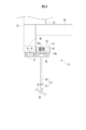
- the side view which shows the coating device of this invention The front view which shows an application
- the coating device 10 includes a coating robot 11, a robot control device 12, a coating unit 13, and a coating control device 14.
- the application robot 11 is, for example, a multi-axis multi-joint type robot, and is provided with arms 11a to 11d in order from the tip.
- the coating robot 11 is provided with a plurality of motors (not shown) for driving the joints (not shown) of the arms 11a to 11d, and the driving is controlled by the robot controller 12.
- a mounting portion 15 is attached to the arm 11 a on the distal end side of the coating robot 11, and a coating unit 13 is mounted on the mounting portion 15.
- the robot controller 12 drives the arms 11a to 11d by driving a plurality of motors of the coating robot 11, and moves the coating unit 13 mounted on the mounting unit 15 to a position facing the coating target. .
- the application unit 13 applies a sealant 25 (see FIG. 4) to the gap between the two vehicle body plates 23 and 24 constituting the vehicle body, for example.
- the coating unit 13 includes a nozzle unit 31, a main body portion 33 having a nozzle support portion 32 that rotatably supports the nozzle unit 31, and a connecting portion that protrudes from a base end portion of the main body portion 33. 34.
- the nozzle support portion 32 is shown in cross section, and illustration of the sealing agent 25 and its flow path is omitted.
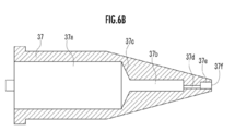
- the nozzle unit 31 is for discharging the sealing agent 25 and includes a cylindrical nozzle cylinder 36 and a nozzle body 37 fixed to the tip of the nozzle cylinder 36.
- the flow path that penetrates the inside of the nozzle body 37 includes a main body flow path portion 37 a (upstream flow path portion), a first flow path portion 37 b, a main body flow path portion 37 a, and A connecting part 37c for connecting the first flow path part 37b, a plurality of (for example, 19) second flow path parts 37d, and a chamber 37e (discharge part) for discharging the sealant 25 formed at the tip part. And.
- the nozzle body 37 has an upstream end formed in a circular shape and a downstream end formed in an elongated quadrilateral shape. Further, the nozzle body 37 is formed so as to change from a circular shape to an elongated quadrilateral shape corresponding to the chamber 37e as it goes from the central portion toward the downstream end side.
- the shape of the nozzle body 37 can be changed as appropriate, and may be formed in a circular cross section from the upstream end to the downstream end.
- the main body flow path portion 37a is formed in a circular shape in a cross section in an orthogonal plane orthogonal to the direction in which the sealant 25 flows.
- the first flow path portion 37b is formed in an elongated cross-sectional shape and has a smaller cross-sectional shape than the main body flow path portion 37a. Note that the first flow path portion 37b may be extended to the upstream end of the nozzle body 37 without providing the main body flow path portion 37a.
- the connecting portion 37c is formed so as to change from the circular shape of the main body flow passage portion 37a to the elongated shape of the first flow passage portion 37b toward the distal end side (downstream end side).
- the chamber 37e is formed in a rectangular shape having an elongated cross section.
- the plurality of second flow path portions 37d connect the first flow path portion 37b and the chamber 37e.
- the sealing agent 25 sent from the nozzle cylinder 36 is sent to the chamber 37e through the main body flow passage portion 37a, the first flow passage portion 37b, and the plurality of second flow passage portions 37d.
- the sealing agent 25 sent to the chamber 37e is discharged to the outside from a nozzle port 37f that is an opening on the front end side of the chamber 37e.
- 6A is a front view seen from the front end side of the nozzle body 37
- FIG. 6B is a sectional view taken along the line VIB-VIB in FIG. 6A
- FIG. 6C is a sectional view taken along the line VIC-VIC in FIG. is there.
- the nozzle port 37f of the nozzle body 37 is formed in a rectangular shape and has directivity.
- the nozzle body 37 discharges the sealing agent 25 in a state where the nozzle body 37 is in contact with the vehicle body plate 23.
- the nozzle unit 31 is set so that its central axis is perpendicular to the surface of the vehicle body plate 23 when viewed from the front (FIG. 2). 2 is the longitudinal direction of the nozzle opening 37f. Further, the central axis of the nozzle unit 31 may be inclined with respect to the surface of the vehicle body plate 23 in a front view (FIG. 2).
- the base end portion of the nozzle cylinder 36 is inserted into support holes 32 a and 32 b formed in the nozzle support portion 32, and the nozzle unit 31 is rotatable around the central axis and is the nozzle support portion 32. Is supported by the nozzle support portion 32 so as to be capable of moving forward and backward.
- a motor 40 is disposed inside the main body 33.
- a first gear 41 connected to the motor 40 is rotatably attached to the lower surface of the main body 33.
- the first gear 41 meshes with a second gear 42 attached to the proximal end portion of the nozzle cylinder 36.
- the rotation of the motor 40 is transmitted to the second gear 42 via the first gear 41, and the nozzle unit 31 composed of the nozzle cylinder 36 and the nozzle body 37 to which the second gear 42 is attached rotates.
- a receiving plate 46 is attached to the base end portion of the nozzle cylinder 36.
- the receiving plate 46 is disposed in the nozzle support portion 32.
- the receiving plate 46 is fixed to the nozzle cylinder 36 and receives the lower end of a coil spring 47 inserted through the nozzle cylinder 36.
- the upper end of the coil spring 47 is in contact with the inner surface of the upper plate portion of the nozzle support portion 32, and the nozzle unit 31 is urged by the coil spring 47 in the protruding direction (downward in FIG. 3). In the state of being biased in the protruding direction, there is a gap between the second gear 42 and the lower surfaces of the nozzle support portion 32 and the main body portion 33, and the nozzle unit 31 can be retracted.
- the vehicle body plates 23 and 24 have convex portions different from the design shape.
- the nozzle unit 31 moves backward against the bias of the coil spring 47. Thereby, even if the nozzle main body 37 is pushed by the convex part of the vehicle body plates 23 and 24, damage to the nozzle unit 31 can be prevented. In addition, you may make it project by the dead weight of the nozzle unit 31, without providing a spring.
- the connecting portion 34 is connected to a supply tube (not shown) of a sealant supply device.
- the supply tube is connected to a supply path (not shown) provided inside the connecting portion 34.
- the sealant 25 supplied from the sealant supply device passes through the supply tube, the supply path of the connecting portion 34, and the supply path (not shown) provided inside the main body 33 to the nozzle cylinder 36 of the nozzle unit 31. Supplied.
- the nozzle unit 31 is in a state in which the nozzle port 37 f is inclined with respect to the surface of the vehicle body plate 23 so that the sealant 25 can be discharged in a state where the nozzle body 37 is in contact with the vehicle body plate 23.
- the gap between the vehicle body plates 23 and 24 is filled with the discharged sealant 25.
- the operator When the sealing agent 25 is applied to the gap between the vehicle body plates 23 and 24 by the application device 10, the operator operates an operation panel (not shown) to drive the application robot 11 and the motor 40 of the application unit 13. Input application execution data. Based on this application execution data, the robot controller 12 drives the application robot 11 to set the nozzle unit 31 of the application unit 13 mounted on the mounting unit 15 to a desired position as shown in FIG.
- the application control device 14 drives the motor 40 of the nozzle unit 31 to rotate the nozzle unit 31 to a desired direction.
- the desired position of the nozzle unit 31 is a position where the tip surface of the nozzle unit 31 contacts the end of the vehicle body plate 23.
- the desired direction of the nozzle unit 31 is such that the longitudinal direction of the nozzle port 37f of the nozzle unit 31 (the left-right direction in FIG. 2) extends over both of the vehicle body plates 23 and 24 at the step portions of the vehicle body plates 23 and 24. Is the right direction.
- the sealing agent supply device When the nozzle unit 31 is set in a desired position and orientation, the sealing agent supply device is driven to supply the sealing agent 25 to the nozzle unit 31.
- the sealant 25 supplied to the nozzle unit 31 is sent to the nozzle body 37 through the nozzle cylinder 36. As shown in FIG. 4, the sealant 25 sent to the nozzle body 37 is discharged toward the vehicle body plates 23 and 24 from the nozzle port 37 f. The gap between the vehicle body plates 23 and 24 is filled with the discharged sealing agent 25.
- the sealant 25 sent from the nozzle cylinder 36 is provided with a main body flow path portion 37 a, a connection portion 37 c, a first flow path portion 37 b, and a plurality of second flow path portions 37 d. Then, it is sent to the chamber 37e and discharged to the outside from a nozzle port 37f that is an opening on the front end side of the chamber 37e.
- the sealing agent 25 Since the sealing agent 25 is sent from the main body flow path portion 37a having a circular cross section to the first flow path portion 37b having an elongated cross section and smaller than the downstream end of the main body flow path portion 37a via the connecting portion 37c, the first flow The pressure is applied to the sealing agent 25 inside the passage portion 37b. Thereby, the sealing agent 25 flows vigorously from the first flow path portion 37b to the second flow path portion 37d.
- the sealing agent 25 in the first flow path portion 37b is vigorously sent to the chamber 37e and is externally supplied from the nozzle port 37f. Discharged. Therefore, the discharge amount at both ends in the longitudinal direction of the chamber 37e is not smaller than that at the center. Thereby, substantially the same amount of the sealing agent 25 can be discharged in the entire range of the chamber 37e.
- the sealing agent 25 can be discharged at substantially the same speed in the entire range of the chamber 37e, the gap between the vehicle body plates 23 and 24 can be filled without unevenness.
- a sufficient amount of sealing agent 25 is also applied to the body plate 24 on the far side in a state where the application amount (primary amount) of the sealing agent 25 to the body plate 23 on the side close to the nozzle body 37 is maintained at an appropriate thickness. Can be applied.
- the nozzle body 37 discharges the sealing agent 25 in a state of being in contact with the vehicle body plate 23, but a gap may be provided between the nozzle body 37 and the vehicle body plate 23. .
- cross-sectional shapes of the main body flow passage portion 37a and the first flow passage portion 37b are not limited to circular and elongated shapes, and can be appropriately changed.
- what is discharged from the nozzle is not limited to a sealing agent, and any material having viscosity may be used.
Abstract
Description
Claims (3)
- 粘性材料を流す流路が形成され、前記流路を流れた粘性材料を吐出するノズルを備え、前記ノズルから吐出される粘性材料を対象物に塗布する塗布装置であって、
前記流路は、
粘性材料を流す第1流路部と、
前記第1流路部の下流端より小さく、前記第1流路部の下流端に連通されて前記第1流路部から流入する粘性材料を流す複数の第2流路部と、
前記複数の第2流路部の下流端全てに連通され、前記複数の第2流路部から流入する粘性材料を吐出する吐出部と、
を備えることを特徴とする塗布装置。 - 請求項1に記載の塗布装置において、
前記流路は、前記第1流路部の上流側に設けられ、前記第1流路部の上流端より大きく、前記第1流路部に粘性材料を流す上流側流路部を備えることを特徴とする塗布装置。 - 請求項1に記載の塗布装置において、
前記吐出部の下流端は細長形状で形成され、
前記ノズルは、上流端が円形状で形成され、下流端が前記吐出部に応じた細長形状で形成されていることを特徴とする塗布装置。
Priority Applications (4)
| Application Number | Priority Date | Filing Date | Title |
|---|---|---|---|
| CN201780055599.0A CN109689222B (zh) | 2016-09-23 | 2017-09-15 | 涂敷装置 |
| US16/334,645 US11065638B2 (en) | 2016-09-23 | 2017-09-15 | Application device |
| JP2018541052A JP6724148B2 (ja) | 2016-09-23 | 2017-09-15 | 塗布装置 |
| CA3037660A CA3037660C (en) | 2016-09-23 | 2017-09-15 | Application device |
Applications Claiming Priority (2)
| Application Number | Priority Date | Filing Date | Title |
|---|---|---|---|
| JP2016186214 | 2016-09-23 | ||
| JP2016-186214 | 2016-09-23 |
Publications (1)
| Publication Number | Publication Date |
|---|---|
| WO2018056227A1 true WO2018056227A1 (ja) | 2018-03-29 |
Family
ID=61689914
Family Applications (1)
| Application Number | Title | Priority Date | Filing Date |
|---|---|---|---|
| PCT/JP2017/033569 WO2018056227A1 (ja) | 2016-09-23 | 2017-09-15 | 塗布装置 |
Country Status (5)
| Country | Link |
|---|---|
| US (1) | US11065638B2 (ja) |
| JP (1) | JP6724148B2 (ja) |
| CN (1) | CN109689222B (ja) |
| CA (1) | CA3037660C (ja) |
| WO (1) | WO2018056227A1 (ja) |
Cited By (1)
| Publication number | Priority date | Publication date | Assignee | Title |
|---|---|---|---|---|
| CN111282740A (zh) * | 2018-12-06 | 2020-06-16 | 现代自动车株式会社 | 密封剂施用装置 |
Families Citing this family (1)
| Publication number | Priority date | Publication date | Assignee | Title |
|---|---|---|---|---|
| CN115815043B (zh) * | 2021-11-03 | 2024-03-26 | 宁德时代新能源科技股份有限公司 | 出胶装置及涂胶设备 |
Citations (7)
| Publication number | Priority date | Publication date | Assignee | Title |
|---|---|---|---|---|
| JPH0316665A (ja) * | 1989-06-14 | 1991-01-24 | Toto Ltd | シャワーヘッド |
| JPH0647669A (ja) * | 1992-07-30 | 1994-02-22 | Babcock Hitachi Kk | キヤビテーシヨンジエツトノズル |
| JP2000334333A (ja) * | 1999-05-31 | 2000-12-05 | Daiko Kennetsu Kk | 流体の整流機構 |
| JP2006122834A (ja) * | 2004-10-29 | 2006-05-18 | Sugino Mach Ltd | キャビテーション安定器 |
| JP2008205059A (ja) * | 2007-02-19 | 2008-09-04 | Tokyo Electron Ltd | 処理液供給装置 |
| WO2014038208A1 (ja) * | 2012-09-06 | 2014-03-13 | 株式会社エンプラス | 点滴灌漑用ドリッパおよびこれを備えた点滴灌漑装置 |
| JP2014069095A (ja) * | 2012-09-27 | 2014-04-21 | Gunze Ltd | 樹脂の塗布ノズル |
Family Cites Families (3)
| Publication number | Priority date | Publication date | Assignee | Title |
|---|---|---|---|---|
| DE3929002A1 (de) * | 1989-09-01 | 1991-03-14 | Schmidt Erwepa Maschf | Vorrichtung zum extrudieren von kunststoff-mehrschichtfolien oder -platten |
| CN1318799C (zh) * | 2004-01-21 | 2007-05-30 | 中国石油化工集团公司<Del/> | 气相介质气化喷嘴及使用方法 |
| JP2016043312A (ja) | 2014-08-22 | 2016-04-04 | 本田技研工業株式会社 | 高粘度材料の塗布方法及び塗布装置並びに高粘度材料塗布物 |
-
2017
- 2017-09-15 JP JP2018541052A patent/JP6724148B2/ja active Active
- 2017-09-15 US US16/334,645 patent/US11065638B2/en active Active
- 2017-09-15 CN CN201780055599.0A patent/CN109689222B/zh active Active
- 2017-09-15 CA CA3037660A patent/CA3037660C/en active Active
- 2017-09-15 WO PCT/JP2017/033569 patent/WO2018056227A1/ja active Application Filing
Patent Citations (7)
| Publication number | Priority date | Publication date | Assignee | Title |
|---|---|---|---|---|
| JPH0316665A (ja) * | 1989-06-14 | 1991-01-24 | Toto Ltd | シャワーヘッド |
| JPH0647669A (ja) * | 1992-07-30 | 1994-02-22 | Babcock Hitachi Kk | キヤビテーシヨンジエツトノズル |
| JP2000334333A (ja) * | 1999-05-31 | 2000-12-05 | Daiko Kennetsu Kk | 流体の整流機構 |
| JP2006122834A (ja) * | 2004-10-29 | 2006-05-18 | Sugino Mach Ltd | キャビテーション安定器 |
| JP2008205059A (ja) * | 2007-02-19 | 2008-09-04 | Tokyo Electron Ltd | 処理液供給装置 |
| WO2014038208A1 (ja) * | 2012-09-06 | 2014-03-13 | 株式会社エンプラス | 点滴灌漑用ドリッパおよびこれを備えた点滴灌漑装置 |
| JP2014069095A (ja) * | 2012-09-27 | 2014-04-21 | Gunze Ltd | 樹脂の塗布ノズル |
Cited By (2)
| Publication number | Priority date | Publication date | Assignee | Title |
|---|---|---|---|---|
| CN111282740A (zh) * | 2018-12-06 | 2020-06-16 | 现代自动车株式会社 | 密封剂施用装置 |
| CN111282740B (zh) * | 2018-12-06 | 2023-05-16 | 现代自动车株式会社 | 密封剂施用装置 |
Also Published As
| Publication number | Publication date |
|---|---|
| US11065638B2 (en) | 2021-07-20 |
| CN109689222B (zh) | 2021-10-22 |
| JPWO2018056227A1 (ja) | 2019-03-28 |
| CA3037660C (en) | 2021-06-22 |
| JP6724148B2 (ja) | 2020-07-15 |
| CA3037660A1 (en) | 2018-03-29 |
| CN109689222A (zh) | 2019-04-26 |
| US20200139396A1 (en) | 2020-05-07 |
Similar Documents
| Publication | Publication Date | Title |
|---|---|---|
| JP6437016B2 (ja) | 塗布装置 | |
| EP2711088B1 (en) | Film-coating nozzle, coating device and coating method | |
| WO2018056227A1 (ja) | 塗布装置 | |
| EP3636352B1 (en) | Sealant discharging nozzle and sealant discharging apparatus | |
| JP2015213907A (ja) | 塗布装置 | |
| JP2016055284A (ja) | 粘性材料の小ビードを吐出する装置及び方法 | |
| JP2019107606A (ja) | 塗工装置 | |
| JP6724147B2 (ja) | 塗布装置 | |
| JP4749141B2 (ja) | 塗装システム | |
| WO2014192579A1 (ja) | 吐出幅可変装置、及び吐出装置 | |
| PT1521642E (pt) | Dispositivo para a aplicação de um fluido. | |
| JP2008246476A (ja) | ガラス用シーラントを塗布するアプリケータノズル及び該アプリケータノズルの使用方法 | |
| CN103752450B (zh) | 喷涂设备 | |
| EP3639934B1 (en) | Sealant discharging nozzle and sealant discharging apparatus | |
| EP3639935B1 (en) | Sealant discharging nozzle and sealant discharging apparatus | |
| JP6057419B2 (ja) | 高粘度流体塗布装置 | |
| JP6443483B2 (ja) | 塗布装置 | |
| JP6496330B2 (ja) | 吐出装置 | |
| JP2007253002A (ja) | 塗布剤の塗布方法とそれに用いる塗布ノズル | |
| JP2009150176A (ja) | コーキングノズル装置 | |
| JP2005262081A5 (ja) |
Legal Events
| Date | Code | Title | Description |
|---|---|---|---|
| 121 | Ep: the epo has been informed by wipo that ep was designated in this application |
Ref document number: 17853000 Country of ref document: EP Kind code of ref document: A1 |
|
| ENP | Entry into the national phase |
Ref document number: 2018541052 Country of ref document: JP Kind code of ref document: A |
|
| ENP | Entry into the national phase |
Ref document number: 3037660 Country of ref document: CA |
|
| NENP | Non-entry into the national phase |
Ref country code: DE |
|
| 122 | Ep: pct application non-entry in european phase |
Ref document number: 17853000 Country of ref document: EP Kind code of ref document: A1 |