以下、本発明の実施形態について、図面を参照しながら説明する。
Hereinafter, embodiments of the present invention will be described with reference to the drawings.
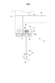
図1に示すように、塗布装置10は、塗布ロボット11と、ロボット制御装置12と、塗布ユニット13と、塗布制御装置14とを備える。
As shown in FIG. 1, the coating device 10 includes a coating robot 11, a robot control device 12, a coating unit 13, and a coating control device 14.
塗布ロボット11は、例えば、多軸多関節型のロボットであり、先端から順にアーム11a~11dが設けられている。塗布ロボット11は、各アーム11a~11dの関節部(図示せず)を駆動する複数のモータ(図示せず)が設けられ、ロボット制御装置12により駆動が制御される。
The application robot 11 is, for example, a multi-axis multi-joint type robot, and is provided with arms 11a to 11d in order from the tip. The coating robot 11 is provided with a plurality of motors (not shown) for driving the joints (not shown) of the arms 11a to 11d, and the driving is controlled by the robot controller 12.
塗布ロボット11の先端側のアーム11aには装着部15が取り付けられており、この装着部15には、塗布ユニット13が装着されている。
A mounting portion 15 is attached to the arm 11 a on the distal end side of the coating robot 11, and a coating unit 13 is mounted on the mounting portion 15.
ロボット制御装置12は、塗布ロボット11の複数のモータを駆動することで、各アーム11a~11dを駆動して、装着部15に装着された塗布ユニット13を塗布対象物に対面する位置まで移動させる。
The robot controller 12 drives the arms 11a to 11d by driving a plurality of motors of the coating robot 11, and moves the coating unit 13 mounted on the mounting unit 15 to a position facing the coating target. .
図2に示すように、塗布ユニット13は、例えば、車体を構成する2枚の車体板23,24の間隙に、シール剤25(図4参照)を塗布する。
As shown in FIG. 2, the application unit 13 applies a sealant 25 (see FIG. 4) to the gap between the two vehicle body plates 23 and 24 constituting the vehicle body, for example.
図3に示すように、塗布ユニット13は、ノズルユニット31と、このノズルユニット31を回転可能に支持するノズル支持部32を有する本体部33と、本体部33の基端部から突出する連結部34とを備える。なお、図3では、ノズル支持部32のみを断面で示し、シール剤25及びその流路の図示を省略している。
As shown in FIG. 3, the coating unit 13 includes a nozzle unit 31, a main body portion 33 having a nozzle support portion 32 that rotatably supports the nozzle unit 31, and a connecting portion that protrudes from a base end portion of the main body portion 33. 34. In FIG. 3, only the nozzle support portion 32 is shown in cross section, and illustration of the sealing agent 25 and its flow path is omitted.
ノズルユニット31は、シール剤25を吐出するものであり、円筒状のノズル筒36と、このノズル筒36の先端部に固定されたノズル本体37とを備えている。
The nozzle unit 31 is for discharging the sealing agent 25 and includes a cylindrical nozzle cylinder 36 and a nozzle body 37 fixed to the tip of the nozzle cylinder 36.
図5及び図6に示すように、ノズル本体37の内部を貫通する流路は、本体流路部37a(上流側流路部)と、第1流路部37bと、本体流路部37a及び第1流路部37bを連結する連結部37cと、複数(例えば、19個)の第2流路部37dと、先端部に形成され、シール剤25を吐出するためのチャンバ37e(吐出部)とを備えている。
As shown in FIGS. 5 and 6, the flow path that penetrates the inside of the nozzle body 37 includes a main body flow path portion 37 a (upstream flow path portion), a first flow path portion 37 b, a main body flow path portion 37 a, and A connecting part 37c for connecting the first flow path part 37b, a plurality of (for example, 19) second flow path parts 37d, and a chamber 37e (discharge part) for discharging the sealant 25 formed at the tip part. And.
ノズル本体37は、上流端が円形状で形成され、下流端が細長の四辺形状で形成されている。また、ノズル本体37は、中央部分から下流端側に向かうにつれて、円形状からチャンバ37eに応じた細長の四辺形状に変化するように形成されている。なお、ノズル本体37の形状は適宜変更可能であり、上流端から下流端まで断面円形状で形成してもよい。
The nozzle body 37 has an upstream end formed in a circular shape and a downstream end formed in an elongated quadrilateral shape. Further, the nozzle body 37 is formed so as to change from a circular shape to an elongated quadrilateral shape corresponding to the chamber 37e as it goes from the central portion toward the downstream end side. The shape of the nozzle body 37 can be changed as appropriate, and may be formed in a circular cross section from the upstream end to the downstream end.
本体流路部37aは、シール剤25が流れる方向に直交する直交面での断面において円形状で形成されている。第1流路部37bは、断面細長形状で形成され、本体流路部37aより断面形状が小さい。なお、本体流路部37aを設けずに、第1流路部37bをノズル本体37の上流端まで延ばすようにしてもよい。
The main body flow path portion 37a is formed in a circular shape in a cross section in an orthogonal plane orthogonal to the direction in which the sealant 25 flows. The first flow path portion 37b is formed in an elongated cross-sectional shape and has a smaller cross-sectional shape than the main body flow path portion 37a. Note that the first flow path portion 37b may be extended to the upstream end of the nozzle body 37 without providing the main body flow path portion 37a.
連結部37cは、先端側(下流端側)に向かうにつれて、本体流路部37aの円形状から第1流路部37bの細長形状に変化するように形成されている。チャンバ37eは、断面細長の矩形状で形成されている。
The connecting portion 37c is formed so as to change from the circular shape of the main body flow passage portion 37a to the elongated shape of the first flow passage portion 37b toward the distal end side (downstream end side). The chamber 37e is formed in a rectangular shape having an elongated cross section.
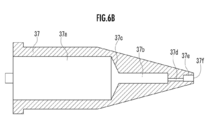
複数の第2流路部37dは、第1流路部37bとチャンバ37eとを連結している。これにより、ノズル筒36から送られたシール剤25は、本体流路部37a、第1流路部37b、複数の第2流路部37dを通って、チャンバ37eに送られる。チャンバ37eに送られたシール剤25は、チャンバ37eの先端側の開口であるノズル口37fから外部に吐出される。なお、図6Aは、ノズル本体37の先端側から見た正面図であり、図6Bは、図6AのVIB-VIB線断面図であり、図6Cは、図6AのVIC-VIC線断面図である。
The plurality of second flow path portions 37d connect the first flow path portion 37b and the chamber 37e. Thereby, the sealing agent 25 sent from the nozzle cylinder 36 is sent to the chamber 37e through the main body flow passage portion 37a, the first flow passage portion 37b, and the plurality of second flow passage portions 37d. The sealing agent 25 sent to the chamber 37e is discharged to the outside from a nozzle port 37f that is an opening on the front end side of the chamber 37e. 6A is a front view seen from the front end side of the nozzle body 37, FIG. 6B is a sectional view taken along the line VIB-VIB in FIG. 6A, and FIG. 6C is a sectional view taken along the line VIC-VIC in FIG. is there.
ノズル本体37のノズル口37fは、矩形状に形成され、指向性を有する。ノズル本体37は、車体板23に当接した状態でシール剤25を吐出する。ノズルユニット31は、その中心軸線が正面視(図2)において車体板23の表面に対して垂直となるようにセットされる。なお、図2における左右方向がノズル口37fの長手方向となる。また、ノズルユニット31の中心軸線が正面視(図2)において車体板23の表面に対して傾いていてもよい。
The nozzle port 37f of the nozzle body 37 is formed in a rectangular shape and has directivity. The nozzle body 37 discharges the sealing agent 25 in a state where the nozzle body 37 is in contact with the vehicle body plate 23. The nozzle unit 31 is set so that its central axis is perpendicular to the surface of the vehicle body plate 23 when viewed from the front (FIG. 2). 2 is the longitudinal direction of the nozzle opening 37f. Further, the central axis of the nozzle unit 31 may be inclined with respect to the surface of the vehicle body plate 23 in a front view (FIG. 2).
図3に示すように、ノズル筒36の基端部は、ノズル支持部32に形成された支持孔32a,32bに挿通され、ノズルユニット31は、中心軸線周りに回転可能で且つノズル支持部32に対して進退可能に、ノズル支持部32に支持されている。
As shown in FIG. 3, the base end portion of the nozzle cylinder 36 is inserted into support holes 32 a and 32 b formed in the nozzle support portion 32, and the nozzle unit 31 is rotatable around the central axis and is the nozzle support portion 32. Is supported by the nozzle support portion 32 so as to be capable of moving forward and backward.
本体部33の内部には、モータ40が配置されている。本体部33の下面には、モータ40に接続される第1ギヤ41が回転可能に取り付けられている。第1ギヤ41は、ノズル筒36の基端部に取り付けられた第2ギヤ42に噛合している。モータ40の回転は、第1ギヤ41を介して第2ギヤ42に伝わり、第2ギヤ42が取り付けられたノズル筒36とノズル本体37とからなるノズルユニット31が回転する。
A motor 40 is disposed inside the main body 33. A first gear 41 connected to the motor 40 is rotatably attached to the lower surface of the main body 33. The first gear 41 meshes with a second gear 42 attached to the proximal end portion of the nozzle cylinder 36. The rotation of the motor 40 is transmitted to the second gear 42 via the first gear 41, and the nozzle unit 31 composed of the nozzle cylinder 36 and the nozzle body 37 to which the second gear 42 is attached rotates.
ノズル筒36の基端部には、受け板46が取り付けられている。この受け板46は、ノズル支持部32内に配置される。受け板46は、ノズル筒36に固定され、ノズル筒36を挿通されたコイルバネ47の下端を受ける。コイルバネ47の上端は、ノズル支持部32の上板部の内面に当接しており、コイルバネ47により、ノズルユニット31は突出方向(図3における下方)に付勢されている。この突出方向に付勢された状態では、第2ギヤ42とノズル支持部32及び本体部33の下面との間に隙間があり、ノズルユニット31は後退可能となる。
A receiving plate 46 is attached to the base end portion of the nozzle cylinder 36. The receiving plate 46 is disposed in the nozzle support portion 32. The receiving plate 46 is fixed to the nozzle cylinder 36 and receives the lower end of a coil spring 47 inserted through the nozzle cylinder 36. The upper end of the coil spring 47 is in contact with the inner surface of the upper plate portion of the nozzle support portion 32, and the nozzle unit 31 is urged by the coil spring 47 in the protruding direction (downward in FIG. 3). In the state of being biased in the protruding direction, there is a gap between the second gear 42 and the lower surfaces of the nozzle support portion 32 and the main body portion 33, and the nozzle unit 31 can be retracted.
車体板23,24に設計形状とは異なる凸部があり、この凸部によりノズル本体37の先端が押されると、コイルバネ47の付勢に抗してノズルユニット31が後退する。これにより、ノズル本体37が車体板23,24の凸部により押されても、ノズルユニット31の破損を防止することができる。なお、バネを設けずに、ノズルユニット31の自重により突出させてもよい。
The vehicle body plates 23 and 24 have convex portions different from the design shape. When the tip of the nozzle body 37 is pushed by the convex portions, the nozzle unit 31 moves backward against the bias of the coil spring 47. Thereby, even if the nozzle main body 37 is pushed by the convex part of the vehicle body plates 23 and 24, damage to the nozzle unit 31 can be prevented. In addition, you may make it project by the dead weight of the nozzle unit 31, without providing a spring.
連結部34には、シール剤供給装置の供給チューブ(図示せず)が連結されている。この供給チューブは、連結部34の内部に設けられた供給路(図示せず)に接続されている。シール剤供給装置から供給されたシール剤25は、供給チューブ、連結部34の供給路、本体部33の内部に設けられた供給路(図示せず)を通ってノズルユニット31のノズル筒36に供給される。
The connecting portion 34 is connected to a supply tube (not shown) of a sealant supply device. The supply tube is connected to a supply path (not shown) provided inside the connecting portion 34. The sealant 25 supplied from the sealant supply device passes through the supply tube, the supply path of the connecting portion 34, and the supply path (not shown) provided inside the main body 33 to the nozzle cylinder 36 of the nozzle unit 31. Supplied.
図4に示すように、ノズルユニット31は、ノズル本体37が車体板23に当接した状態でシール剤25を吐出できるように、車体板23の表面に対してノズル口37fが傾斜された状態で車体板23に当接する。この状態で、ノズル口37fから車体板23,24の段差部に向けてシール剤25を吐出すると、吐出されたシール剤25により、車体板23,24の間隙が埋められる。
As shown in FIG. 4, the nozzle unit 31 is in a state in which the nozzle port 37 f is inclined with respect to the surface of the vehicle body plate 23 so that the sealant 25 can be discharged in a state where the nozzle body 37 is in contact with the vehicle body plate 23. To contact the vehicle body plate 23. In this state, when the sealant 25 is discharged from the nozzle port 37f toward the step portions of the vehicle body plates 23 and 24, the gap between the vehicle body plates 23 and 24 is filled with the discharged sealant 25.
塗布装置10により、車体板23,24の間隙にシール剤25を塗布する場合、オペレータが操作パネル(図示せず)を操作して、塗布ロボット11、塗布ユニット13のモータ40を駆動するための塗布実行データを入力する。この塗布実行データに基づいて、ロボット制御装置12は塗布ロボット11を駆動して、図1に示すように、装着部15に装着された塗布ユニット13のノズルユニット31を所望する位置にセットする。
When the sealing agent 25 is applied to the gap between the vehicle body plates 23 and 24 by the application device 10, the operator operates an operation panel (not shown) to drive the application robot 11 and the motor 40 of the application unit 13. Input application execution data. Based on this application execution data, the robot controller 12 drives the application robot 11 to set the nozzle unit 31 of the application unit 13 mounted on the mounting unit 15 to a desired position as shown in FIG.
次に、図2に示すように、塗布制御装置14は、ノズルユニット31のモータ40を駆動して、ノズルユニット31を所望する向きまで回転させる。
Next, as shown in FIG. 2, the application control device 14 drives the motor 40 of the nozzle unit 31 to rotate the nozzle unit 31 to a desired direction.
なお、ノズルユニット31の所望する位置とは、ノズルユニット31の先端面が、車体板23の端部に当接する位置である。また、ノズルユニット31の所望する向きとは、ノズルユニット31のノズル口37fの長手方向(図2における左右方向)が、車体板23,24の段差部で車体板23,24の両方に跨るような向きである。
The desired position of the nozzle unit 31 is a position where the tip surface of the nozzle unit 31 contacts the end of the vehicle body plate 23. The desired direction of the nozzle unit 31 is such that the longitudinal direction of the nozzle port 37f of the nozzle unit 31 (the left-right direction in FIG. 2) extends over both of the vehicle body plates 23 and 24 at the step portions of the vehicle body plates 23 and 24. Is the right direction.
ノズルユニット31が所望する位置及び向きにセットされると、シール剤供給装置を駆動して、シール剤25をノズルユニット31に供給する。ノズルユニット31に供給されたシール剤25は、ノズル筒36を通ってノズル本体37に送られる。そして、図4に示すように、ノズル本体37に送られたシール剤25は、ノズル口37fから車体板23,24に向けて吐出される。この吐出されたシール剤25により、車体板23,24の間隙が埋められる。
When the nozzle unit 31 is set in a desired position and orientation, the sealing agent supply device is driven to supply the sealing agent 25 to the nozzle unit 31. The sealant 25 supplied to the nozzle unit 31 is sent to the nozzle body 37 through the nozzle cylinder 36. As shown in FIG. 4, the sealant 25 sent to the nozzle body 37 is discharged toward the vehicle body plates 23 and 24 from the nozzle port 37 f. The gap between the vehicle body plates 23 and 24 is filled with the discharged sealing agent 25.
本実施形態では、ノズル筒36から送られたシール剤25は、図5に示すように、本体流路部37a、連結部37c、第1流路部37b、複数の第2流路部37dを通って、チャンバ37eに送られ、チャンバ37eの先端側の開口であるノズル口37fから外部に吐出される。
In the present embodiment, as shown in FIG. 5, the sealant 25 sent from the nozzle cylinder 36 is provided with a main body flow path portion 37 a, a connection portion 37 c, a first flow path portion 37 b, and a plurality of second flow path portions 37 d. Then, it is sent to the chamber 37e and discharged to the outside from a nozzle port 37f that is an opening on the front end side of the chamber 37e.
断面円形状の本体流路部37aから、連結部37cを介して、断面細長形状で本体流路部37aの下流端より小さい第1流路部37bにシール剤25は送られるので、第1流路部37bの内部では、シール剤25に圧力がかかった状態となっている。これにより、第1流路部37bから第2流路部37dに勢いよくシール剤25が流れる。
Since the sealing agent 25 is sent from the main body flow path portion 37a having a circular cross section to the first flow path portion 37b having an elongated cross section and smaller than the downstream end of the main body flow path portion 37a via the connecting portion 37c, the first flow The pressure is applied to the sealing agent 25 inside the passage portion 37b. Thereby, the sealing agent 25 flows vigorously from the first flow path portion 37b to the second flow path portion 37d.
さらに、第2流路部37dは、第1流路部37bの下流端より小さいので、第1流路部37b内にあるシール剤25は、勢いよくチャンバ37eに送られ、ノズル口37fから外部に吐出される。したがって、チャンバ37eの長手方向の両端部における吐出量が、中央部より少なくなることがない。これにより、チャンバ37eの全範囲においてほぼ同じ量のシール剤25を吐出することができる。
Further, since the second flow path portion 37d is smaller than the downstream end of the first flow path portion 37b, the sealing agent 25 in the first flow path portion 37b is vigorously sent to the chamber 37e and is externally supplied from the nozzle port 37f. Discharged. Therefore, the discharge amount at both ends in the longitudinal direction of the chamber 37e is not smaller than that at the center. Thereby, substantially the same amount of the sealing agent 25 can be discharged in the entire range of the chamber 37e.
チャンバ37eの全範囲においてほぼ同じ速度でシール剤25を吐出することができるので、ムラなく車体板23,24の間隙を埋めることができる。特に、ノズル本体37に近い側の車体板23へのシール剤25の塗布量(盛り量)を適切な厚さに維持した状態で、遠い側の車体板24へも十分な量のシール剤25を塗布することができる。
Since the sealing agent 25 can be discharged at substantially the same speed in the entire range of the chamber 37e, the gap between the vehicle body plates 23 and 24 can be filled without unevenness. In particular, a sufficient amount of sealing agent 25 is also applied to the body plate 24 on the far side in a state where the application amount (primary amount) of the sealing agent 25 to the body plate 23 on the side close to the nozzle body 37 is maintained at an appropriate thickness. Can be applied.
上記実施形態では、ノズル本体37は、車体板23に当接した状態でシール剤25を吐出するようにしているが、ノズル本体37と車体板23との間に隙間を設けるようにしてもよい。
In the above embodiment, the nozzle body 37 discharges the sealing agent 25 in a state of being in contact with the vehicle body plate 23, but a gap may be provided between the nozzle body 37 and the vehicle body plate 23. .
また、本体流路部37a及び第1流路部37bの断面形状は、円形及び細長形状に限らず、適宜変更可能である。
Further, the cross-sectional shapes of the main body flow passage portion 37a and the first flow passage portion 37b are not limited to circular and elongated shapes, and can be appropriately changed.
さらに、ノズルから吐出するものはシール剤に限らず、粘性を有する材料であればよい。
Furthermore, what is discharged from the nozzle is not limited to a sealing agent, and any material having viscosity may be used.