WO2018056047A1 - コイル、磁性コア、及びリアクトル - Google Patents
コイル、磁性コア、及びリアクトル Download PDFInfo
- Publication number
- WO2018056047A1 WO2018056047A1 PCT/JP2017/031940 JP2017031940W WO2018056047A1 WO 2018056047 A1 WO2018056047 A1 WO 2018056047A1 JP 2017031940 W JP2017031940 W JP 2017031940W WO 2018056047 A1 WO2018056047 A1 WO 2018056047A1
- Authority
- WO
- WIPO (PCT)
- Prior art keywords
- coil
- winding
- magnetic core
- core
- reactor
- Prior art date
- Legal status (The legal status is an assumption and is not a legal conclusion. Google has not performed a legal analysis and makes no representation as to the accuracy of the status listed.)
- Ceased
Links
Images


Classifications
-
- H—ELECTRICITY
- H01—ELECTRIC ELEMENTS
- H01F—MAGNETS; INDUCTANCES; TRANSFORMERS; SELECTION OF MATERIALS FOR THEIR MAGNETIC PROPERTIES
- H01F27/00—Details of transformers or inductances, in general
- H01F27/24—Magnetic cores
-
- H—ELECTRICITY
- H01—ELECTRIC ELEMENTS
- H01F—MAGNETS; INDUCTANCES; TRANSFORMERS; SELECTION OF MATERIALS FOR THEIR MAGNETIC PROPERTIES
- H01F27/00—Details of transformers or inductances, in general
- H01F27/28—Coils; Windings; Conductive connections
- H01F27/2847—Sheets; Strips
-
- H—ELECTRICITY
- H01—ELECTRIC ELEMENTS
- H01F—MAGNETS; INDUCTANCES; TRANSFORMERS; SELECTION OF MATERIALS FOR THEIR MAGNETIC PROPERTIES
- H01F27/00—Details of transformers or inductances, in general
- H01F27/24—Magnetic cores
- H01F27/255—Magnetic cores made from particles
-
- H—ELECTRICITY
- H01—ELECTRIC ELEMENTS
- H01F—MAGNETS; INDUCTANCES; TRANSFORMERS; SELECTION OF MATERIALS FOR THEIR MAGNETIC PROPERTIES
- H01F27/00—Details of transformers or inductances, in general
- H01F27/24—Magnetic cores
- H01F27/26—Fastening parts of the core together; Fastening or mounting the core on casing or support
- H01F27/263—Fastening parts of the core together
-
- H—ELECTRICITY
- H01—ELECTRIC ELEMENTS
- H01F—MAGNETS; INDUCTANCES; TRANSFORMERS; SELECTION OF MATERIALS FOR THEIR MAGNETIC PROPERTIES
- H01F27/00—Details of transformers or inductances, in general
- H01F27/28—Coils; Windings; Conductive connections
- H01F27/32—Insulating of coils, windings, or parts thereof
-
- H—ELECTRICITY
- H01—ELECTRIC ELEMENTS
- H01F—MAGNETS; INDUCTANCES; TRANSFORMERS; SELECTION OF MATERIALS FOR THEIR MAGNETIC PROPERTIES
- H01F37/00—Fixed inductances not covered by group H01F17/00
-
- H—ELECTRICITY
- H01—ELECTRIC ELEMENTS
- H01F—MAGNETS; INDUCTANCES; TRANSFORMERS; SELECTION OF MATERIALS FOR THEIR MAGNETIC PROPERTIES
- H01F27/00—Details of transformers or inductances, in general
- H01F27/02—Casings
- H01F27/022—Encapsulation
-
- H—ELECTRICITY
- H01—ELECTRIC ELEMENTS
- H01F—MAGNETS; INDUCTANCES; TRANSFORMERS; SELECTION OF MATERIALS FOR THEIR MAGNETIC PROPERTIES
- H01F27/00—Details of transformers or inductances, in general
- H01F27/28—Coils; Windings; Conductive connections
- H01F27/32—Insulating of coils, windings, or parts thereof
- H01F27/327—Encapsulating or impregnating
Definitions
- the present invention relates to a coil, a magnetic core, and a reactor.
- This application claims priority based on the Japanese application “Japanese Patent Application No. 2016-184615” dated September 21, 2016, and uses all the contents described in the above Japanese application.
- FIG. 4 and FIG. 5 of Patent Document 1 show, as a reactor for an in-vehicle converter, a coil having one rectangular cylindrical winding portion formed by spirally winding a winding, and a pair of E-shaped split cores. What is provided with the magnetic core which combines is disclosed.
- the magnetic core includes a middle leg (inner core part 31) disposed on the inner periphery of the winding part, a pair of side legs disposed on the outer periphery of the winding part and sandwiching the middle leg, and the middle leg and both legs. And two connecting portions for connecting them.
- the coil of the present disclosure includes: It has a cylindrical winding part formed by winding a winding, The said winding part is provided with two coil recessed parts provided so that a dent direction might become reverse direction mutually toward the inner space enclosed by the internal peripheral surface.
- the magnetic core of the present disclosure is A middle leg portion arranged on the inner circumference of the coil winding portion, two side leg portions arranged on the outer circumference of the winding portion and sandwiching the middle leg portion, and sandwiching the middle leg portion and both side leg portions And two connecting portions for connecting these,
- the middle leg is Including an overhanging portion not sandwiched between the two side legs, To the inside of the middle leg portion, comprising two core recesses provided so that the recess directions are opposite to each other,
- Each side leg is A convex surface is provided that protrudes toward each core recess and is disposed with a predetermined gap between each core recess.
- the reactor of the present disclosure is The coil of the present disclosure described above and the magnetic core of the present disclosure described above, Each coil recess is disposed between each core recess of the middle leg and the convex surface of each side leg, A portion other than the coil recess in the winding portion is exposed without being covered by the magnetic core.
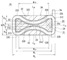
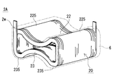
- FIG. FIG. 2 is a cross-sectional view of the reactor according to the first embodiment taken along the line (II)-(II) shown in FIG. 1 is a schematic perspective view showing a coil according to Embodiment 1.
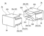
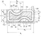
- FIG. FIG. 3 is an exploded perspective view showing a magnetic core according to the first embodiment. It is a cross-sectional view which shows the state in which the reactor of Embodiment 1 was accommodated in the case. It is a cross-sectional view which shows the reactor of Embodiment 2.
- a reactor having a low installation height, low loss, and excellent heat dissipation is desired.
- a coil and a magnetic core capable of constructing such a reactor are desired.
- FIG. 4 of Patent Document 1 a configuration in which the reactor is installed on the installation target so that the axial direction of the coil winding portion is parallel to the mounting surface on which the reactor is to be installed (hereinafter referred to as a horizontal configuration). Is).
- the height from the mounting surface (hereinafter sometimes referred to as the installation height) can be reduced.
- FIG. 4 a configuration in which the reactor is installed on the installation target so that the axial direction of the coil winding portion is parallel to the mounting surface on which the reactor is to be installed.
- the lower surface located in the installation object side in the outer peripheral surface of a winding part and the upper surface in the opposing position are exposed without covering with a magnetic core, and the lower surface of a winding part is mounted in the mounting object. Proximity to the surface. By doing so, the heat of the coil can be easily transmitted to the installation target, and it can be easily dissipated from the upper surface of the winding portion to the surrounding atmosphere, and the heat dissipation is excellent.
- the magnetic flux to the winding portion described above It is easy to reduce the increase in loss.
- the side leg is interposed between the long side part of the winding part and the mounting surface of the installation target, the installation height is increased by the thickness of the side leg, and the heat is dissipated from the coil to the installation target. It also causes a decline in sex.
- an object is to provide a reactor having a low installation height, low loss, and excellent heat dissipation. Another object is to provide a coil and a magnetic core that can construct a reactor having a low installation height, low loss, and excellent heat dissipation.
- the coil of the present disclosure and the magnetic core of the present disclosure described above can construct a reactor having a low installation height, low loss, and excellent heat dissipation.
- the reactor of the present disclosure described above has a low installation height, low loss, and excellent heat dissipation.
- a coil according to an aspect of the present disclosure has a cylindrical winding part formed by winding a winding, The said winding part is provided with two coil recessed parts provided so that a dent direction might become reverse direction mutually toward the inner space enclosed by the internal peripheral surface.
- a reactor having a low installation height, low loss, and excellent heat dissipation can be constructed. Details are as follows.
- the coil described above can use the coil concave portion of the winding portion as the magnetic core arrangement location. If a magnetic core (particularly a magnetic core of (5) described later) is assembled to the coil and a part of the magnetic core is disposed in the coil recess, the coil recess and the magnetic core partially overlap, The size of the assembly including the coil and the magnetic core can be reduced. Therefore, a reactor having a low installation height can be constructed by using the above-described coil, preferably in a horizontally placed form.
- the coil concave portion of the winding portion is the magnetic core arrangement portion and the portion other than the coil concave portion in the winding portion is an exposed portion that is not covered by the magnetic core, at least a part of the exposed portion is installed. It can be brought close to the target mounting surface or exposed to the surrounding atmosphere. Therefore, a reactor having excellent heat dissipation can be constructed by using the above coil.
- the coil concave portion of the winding portion can be used as a magnetic core arrangement location, and the coil concave portion can be sandwiched between a location arranged in the winding portion of the magnetic core and a location arranged in the coil concave portion. Therefore, even if the end face shape of the winding part is horizontally long and the coil concave part is relatively long, it is easy to reduce the loss due to the linkage of the leakage magnetic flux. Therefore, a low-loss reactor or the like can be constructed by using the above coil.
- the above form is a flat coil and can be installed horizontally. Therefore, the said form can construct
- the two coil recesses may be arranged to face each other.
- the above-mentioned form can be made, for example, a symmetrical shape in which the coil concave portions face each other, and it is easier to form a coil and to allow the magnetic flux to flow through the magnetic core in a well-balanced manner than in the asymmetric case. Therefore, the above configuration can construct a reactor having a low installation height, low loss, excellent heat dissipation, and a reactor excellent in manufacturability and excellent in electromagnetic balance.
- the above configuration can improve the insulation between the magnetic core and surrounding parts. Therefore, the above-described configuration can construct a reactor having a low installation height, low loss, and excellent heat dissipation, and is also excellent in insulation.
- a magnetic core according to an aspect of the present disclosure is provided.
- a middle leg portion arranged on the inner circumference of the coil winding portion, two side leg portions arranged on the outer circumference of the winding portion and sandwiching the middle leg portion, and sandwiching the middle leg portion and both side leg portions And two connecting portions for connecting these,
- the middle leg is Including an overhanging portion not sandwiched between the two side legs, To the inside of the middle leg portion, comprising two core recesses provided so that the recess directions are opposite to each other,
- Each side leg is A convex surface is provided that protrudes toward each core recess and is disposed with a predetermined gap between each core recess.
- the gap between the core concave portion of the middle leg portion and the convex surface of the side leg portion can be used as an arrangement location of the coil winding portion. If a coil (particularly the coil of (1) described above) is assembled to the magnetic core, the middle leg portion is inserted and arranged in the winding portion, and a part of the winding portion is arranged in the gap, the magnetic core The size of the assembly including the magnetic core and the coil can be reduced by overlapping the part of the coil and the part of the winding part. Therefore, by using the magnetic core described above, the installation height is preferably set so that the axial direction of the middle leg portion is parallel to the placement surface of the installation target (corresponding to the horizontal installation form). It is possible to build a reactor with low.
- the gap between the core concave portion of the middle leg portion and the convex surface of the side leg portion is used as a part of the winding portion, and the other part of the winding portion surrounds the protruding portion of the middle leg portion. If this is arranged, the other part of the winding part can be an exposed part that is not covered by the magnetic core. At least a part of the exposed portion can be brought close to the placement surface to be installed, or exposed to the surrounding atmosphere. Therefore, by using the magnetic core, a reactor having excellent heat dissipation can be constructed.
- each side leg part is provided so that each core recessed part of a middle leg part may be filled, and since a middle leg part and a side leg part are included, the leakage magnetic flux can be reduced. Therefore, even if the outer shape of the cross section (described later) of the magnetic core is horizontally long, if a part of the winding part is arranged in the gap between the core concave part of the middle leg part and the convex surface of the side leg part, the leakage flux chain Loss caused by crossing can be reduced and a low-loss reactor can be constructed.
- the above form is a flat magnetic core and can be installed horizontally. Therefore, the said form can construct
- the above-mentioned form can be formed into a symmetrical shape in which, for example, the core concave portions face each other and the convex surfaces face each other, and the magnetic core can be easily formed and the magnetic flux can be passed in a balanced manner as compared with the asymmetric case. Therefore, the above configuration can construct a reactor having a low installation height, low loss, excellent heat dissipation, and a reactor excellent in manufacturability and excellent in electromagnetic balance.
- the above-mentioned form can be an integral molded product composed of a composite material molded body, or an assembly of a plurality of divided core pieces composed of at least one of a composite material molded body and a powder compacted body.
- the degree of freedom of selection is high.
- each of the split core pieces is provided with one of the connecting parts, and an intermediate leg piece that forms a part of the middle leg part and two side legs that form a part of each of the side leg parts.
- the form provided with a piece is mentioned.
- the above form is easy to assemble with the coil and the number of parts to be assembled is small. Therefore, the said form can construct a reactor etc. while being able to construct
- a reactor according to an aspect of the present disclosure is: The coil according to any one of (1) to (4), and the magnetic core according to any one of (5) to (9), Each coil recess is disposed between each core recess of the middle leg and the convex surface of each side leg, A portion other than the coil recess in the winding portion is exposed without being covered by the magnetic core.
- the reactor includes a coil having a specific shape including a coil recess, and a magnetic core having a specific shape including a core recess in the middle leg and a convex surface in the side leg, and each coil recess has a middle leg. It arrange
- the size of the reactor can be reduced by overlapping the coil concave portion with the middle leg portion and the side leg portion.
- said reactor makes a part (mainly coil recessed part) of a winding part into the location covered with a magnetic core, and makes the other part (mainly other than coil recessed part) of a winding part into the exposed part which is not covered with a magnetic core. .
- the reactor is preferably in a horizontally placed form, so that the installation height can be lowered, and the loss is low and the heat dissipation is excellent.
- the said side leg part has a form provided with a part of the exposed part from the said magnetic core in the said winding part, and a flush surface.
- FIGS. 2 and 5 are cross-sectional views of the reactor 1A cut along a plane orthogonal to the axial direction of the coil 2A.
- a reactor 1A includes a coil 2A including one cylindrical winding portion 20 formed by winding a winding 2w as shown in FIG. 1, and a magnetic core 3A disposed inside and outside the coil 2A. Is provided.
- the magnetic core 3 ⁇ / b> A includes a middle leg portion 31 disposed on the inner periphery of the winding portion 20 of the coil 2 ⁇ / b> A and two sides sandwiching the middle leg portion 31 disposed on the outer periphery of the winding portion 20.
- Two connecting portions 34 and 35 (FIGS.
- the magnetic core 3A is an assembly obtained by deforming a pair of E-shaped split cores (FIG. 4).
- Reactor 1A of this example is installed so that the axial direction of winding part 20 (or the axial direction of middle leg part 31) is parallel to the mounting surface of an installation target (not shown) such as a converter case. Used in horizontal form.
- the reactor 1A of Embodiment 1 includes the coil 2A of Embodiment 1 having a specific shape in which a part of the cylindrical winding portion 20 is recessed inward as shown in FIG. Further, the reactor 1A according to the first embodiment is provided with a portion (an overhanging portion 31p) that is not sandwiched between the side leg portions 32 and 33 in the middle leg portion 31 as shown in FIG. 2, and as shown in FIG.
- the magnetic core 3 ⁇ / b> A according to the first embodiment having a specific shape in which a part of the leg portion 31 is recessed inward and the side leg portions 32 and 33 protrude toward the recess of the middle leg portion 31 is provided. Further, as shown in FIG.
- the reactor 1 ⁇ / b> A has the above-described recessed portion (coil recessed portions 22, 23) in the winding portion 20 side of the recessed portion (core recessed portions 312, 313) of the middle leg portion 31.
- the portions sandwiched between the protruding portions (convex surfaces 320, 330) of the leg portions 32, 33 are covered with the magnetic core 3A, and the portions other than the recessed portion of the winding portion 20 are exposed portions not covered with the magnetic core 3A.
- each component will be described in detail.
- the coil 2A of the first embodiment includes a cylindrical winding part 20 in which one winding 2w is spirally wound.
- the winding part 20 is provided with two coil recessed parts 22 and 23 provided so that the dent directions are opposite to each other toward the inner space surrounded by the inner peripheral surface thereof.
- the two coil recesses 22 and 23 are arranged to face each other. 2 and 3, the concave direction of the coil concave portion 22 is downward, the concave direction of the coil concave portion 23 is upward, and the concave portion is concave in the opposite direction at the same position in the width direction of the winding portion 20 (left and right direction in FIG. 2). Indicates the case.
- the winding portion 20 in this example has a horizontally long appearance that is enclosed in a horizontally long rectangular parallelepiped.
- the winding portion 20 has a long side portion of the horizontally long rectangular parallelepiped cylindrical body that is recessed toward the inside, and a center portion in the width direction is constricted, and the height increases as the distance from the center portion in the width direction increases. It is a ribbon-like cylinder that grows.
- the coil recesses 22, 23 are formed by using the inner space as the location where the middle leg 31 is disposed and the coil recesses 22, 23 as locations where the side legs 32, 33 are disposed. It is sandwiched between the middle leg portion 31 and the side leg portions 32 and 33, and portions other than the coil recess portions 22 and 23 are exposed from the magnetic core 3A.
- the winding 2w in this example is a covered wire including a conductor wire made of copper or the like and an insulating coating made of an insulating material such as polyamideimide covering the outer periphery of the conductor wire, and a rectangular wire having a rectangular cross-sectional shape. It is.
- the winding part 20 of this example is an edgewise coil.
- the winding 2w can be a wire having various shapes such as a round wire. When a rectangular wire edgewise coil is used as in this example, the space factor is increased and the size can be reduced (especially, the length can be easily reduced) as compared to a round wire coil. It is easy to make the outer peripheral surface of the turning part 20 smooth.
- the coil recesses 22 and 23 are formed as arcuate surfaces, and in the installed state, the installation surfaces 235 and 235 located below, the opposing surfaces 225 and 225 located above and facing the installation surface 235, and the width direction
- the side surfaces located on both sides are formed by flat surfaces (see FIG. 2).
- FIG. 3 illustrates a case where each end of the winding 2w is drawn upward so as to be separated from the winding part 20, the drawing direction, the drawing length, and the like can be changed as appropriate.
- the coil recesses 22 and 23 in this example are both arc-shaped (FIG. 2), but can be changed as appropriate. If it is circular arc like this example, the square part in the winding part 20 can be reduced, and it is easy to manufacture the coil 2A. In addition, it is expected that the magnetic core 3A corresponding to the winding portion 20 can be reduced in the angular portion, so that cracks and the like are not easily generated, and the assembling workability is excellent.
- the coil recesses 22 and 23 in this example have the same shape and the same size as shown in FIG. 2, the formation positions in the width direction are equal, and the formation position in the height direction is set to the center line L H in the height direction.
- the center is symmetrical. Therefore, the end surface shape and cross-sectional shape of the winding portion 20 is symmetrical about the center line L W in the width direction, and is symmetrical about the center line L H in the height direction.
- the shape and size of the coil recesses 22 and 23 (bending radius, protruding height to the inside of the winding part 20, etc.), the formation position, etc. are different, and the end face shape and the cross-sectional shape of the winding part 20 are non-linear.
- each coil recessed part 22 and 23 the space
- the inner peripheral surfaces of the coil recesses 22 and 23 are not in contact with each other, and a predetermined gap H 2 (here, the shortest distance between the coil recesses 22 and 23) is provided at the center of the winding portion 20 in the width direction.
- the opening widths W 22 and W 23 of the coil recesses 22 and 23 are about 20% to 90% of the width W 2 of the winding part 20, and the maximum depths H 22 and H 23 of the coil recesses 22 and 23 are windings.
- the height H of the portion 20 may be about 10% or more and less than 50%.
- the ratio of the long side to the short side of the virtual rectangle exceeds 1.
- the installation height of the reactor 1A tends to be relatively small.
- the ratio is too large, the productivity of the coil 2 ⁇ / b> A is reduced, and therefore the ratio can be set to about 4.0 or less in consideration of manufacturability. If the absolute value of the short side length (height H) is small, the installation height can be further reduced.
- a manufacturing method of the coil 2A including the coil recesses 22 and 23 for example, a method of forming a cylindrical body including the coil recesses 22 and 23 by spirally winding the winding 2w, and winding the winding 2w spirally.
- a method of forming the coil recesses 22 and 23 by, for example, pressing a predetermined position of the cylindrical body after forming a rectangular cylindrical body or a cylindrical body can be used.
- the coil 2 ⁇ / b> A can include a resin mold portion 6 that covers at least a part of the outer periphery of the winding portion 20.
- the resin mold portion 6 that covers substantially the entire inside and outside of the winding portion 20 is indicated by a virtual line (two-dot chain line), but at least a part of the inner and outer peripheral surfaces and the end surface of the winding portion 20. It is also possible to adopt a form that is exposed without covering. For example, if the exposed part from the magnetic core 3 ⁇ / b> A in the winding part 20 is also exposed from the resin mold part 6, it is easy to improve heat dissipation.
- the electrical insulation between the coil 2A and the magnetic core 3A can be improved.
- the electrical insulation between the coil 2A and the magnetic core 3A can be enhanced by using the above-described covered wire as the winding 2w.
- Examples of the constituent material of the resin mold portion 6 include insulating resins such as thermoplastic resins and thermosetting resins.
- the thermoplastic resin include polyphenylene sulfide (PPS) resin, polytetrafluoroethylene (PTFE) resin, liquid crystal polymer (LCP), polyamide (PA) resin such as nylon 6 and nylon 66, polybutylene terephthalate (PBT) resin, and acrylonitrile. -Butadiene styrene (ABS) resin etc. are mentioned.
- Examples of the thermosetting resin include unsaturated polyester resins, epoxy resins, urethane resins, and silicone resins.
- the insulating resin can contain nonmagnetic and nonmetallic powders such as alumina and silica. In this case, heat dissipation and electrical insulation can be improved.
- the magnetic core 3 ⁇ / b> A has a middle leg portion 31 interposed between the side leg portions 32 and 33, which are in the order of the side leg portion 32, the middle leg portion 31, and the side leg portion 33. In an overlapped state, it is sandwiched between two connecting portions 34 and 35 that are arranged to face each other.
- the middle leg portion 31 includes two core concave portions 312 and 313 provided so that the dent directions are opposite to each other toward the inside, and the side leg portions 32 and 33 are respectively provided with the core concave portions 312 and 313.
- projecting surfaces 320 and 330 that are arranged with predetermined gaps between the core recesses 312 and 313.
- the two core concave portions 312 and 313 are opposed to each other, and the two convex surfaces 320 and 330 are opposed to each other.
- the concave direction of the core concave portion 312 and the protruding direction of the convex surface 320 are downward
- the concave direction of the core concave portion 313 and the convex direction of the convex surface 330 are upward, and are opposite at the same position in the width direction in the cross section of the magnetic core 3A.
- the case where the core concave portions 312 and 313 are recessed in the direction of, and the convex surfaces 320 and 330 protrude is shown.
- the magnetic core 3A of this example has a horizontally long appearance that is enclosed in a horizontally long rectangular parallelepiped (FIG. 1).
- the middle leg part 31 includes an interposition part 31d sandwiched between the two side leg parts 32 and 33 and an overhanging part 31p not sandwiched between the two side leg parts 32 and 33.
- the point including the overhanging portion 31p is one of the differences from the conventional E-shaped magnetic core in which the width of the middle leg is equal to or less than the width of the side leg.
- the overhanging portion 31p is shown with cross hatching so that it can be easily understood.
- the gap between the core concave portion 312 and the convex surface 320 is used as the location where the coil concave portion 22 is arranged
- the gap between the core concave portion 313 and the convex surface 330 is used as the location where the coil concave portion 23 is arranged
- the protruding portion 31p of the middle leg portion 31 is used. Is a place other than the coil recesses 22 and 23 in the winding part 20.
- the coil recesses 22 and 23 are covered with the magnetic core 3A, and portions other than the coil recesses 22 and 23 are exposed from the magnetic core 3A (FIGS. 1 and 2). 2).
- the magnetic core 3 ⁇ / b> A can include a molded body of a composite material including magnetic powder and resin.
- the particles of the magnetic powder include particles composed of soft magnetic metals and soft magnetic non-metals, and coated particles including an insulating coating composed of phosphate or the like on the outer periphery of the soft magnetic metal particles.
- the soft magnetic metal include iron group metals such as pure iron and iron base alloys (Fe—Si alloy, Fe—Ni alloy, etc.), and examples of the soft magnetic nonmetal include ferrite.
- the content of the magnetic powder in the composite material is 30% by volume to 80% by volume, and the content of the resin is 10% by volume to 70% by volume.
- the content of the magnetic powder can be 50% by volume or more, further 55% by volume or more, and 60% by volume or more.
- the content of the magnetic powder can be 75% by volume or less, further 70% by volume or less, and the resin content can be more than 30% by volume.
- the resin in the composite material examples include the thermosetting resin, the thermoplastic resin, the room temperature curable resin, and the low temperature curable resin described in the section of the resin mold portion 6 described above.
- BMC Bulk molding compound in which calcium carbonate or glass fiber is mixed with unsaturated polyester, millable silicone rubber, millable urethane rubber, or the like can also be used.
- a composite material containing non-magnetic and non-metallic powder such as alumina or silica can be obtained.
- the content of the non-magnetic and non-metallic powder is 0.2% by mass or more and 20% by mass or less, further 0.3% by mass or more and 15% by mass or less, and 0.5% by mass or more and 10% by mass or less.
- the molded body of the composite material can be manufactured by an appropriate molding method such as injection molding or cast molding.
- an appropriate molding method such as injection molding or cast molding.
- the coil 2A is housed in a molding die or case 4 (FIG. 5) and the composite material in a fluid state is filled into the inside and outside of the coil 2A, an integrally formed magnetic core 3A can be manufactured.
- a mold having an appropriate shape is used, it is possible to manufacture a split core piece composed of a composite material molded body.
- a molded body of a composite material can be easily molded even in a complicated shape, and is excellent in manufacturability.
- the magnetic core 3A can include a compacted body containing magnetic powder.
- a compacted body containing magnetic powder typically, a mixed powder containing magnetic powder and a binder is compression-molded into a predetermined shape, and further subjected to heat treatment after molding.
- the binder a resin or the like can be used, and the content thereof is about 30% by volume or less. When heat treatment is performed, the binder disappears or becomes a heat-denatured product.
- a mold having an appropriate shape it is possible to manufacture a split core piece composed of a compacted body.
- the compacted body has a higher content of magnetic powder than the compacted body of the composite material, and can easily construct a magnetic core having a high saturation magnetic flux density.
- the magnetic core 3A can include a laminate in which soft magnetic plates such as silicon steel plates are laminated, a sintered body such as a ferrite core, and the like.
- the magnetic core 3A can be provided with a gap material or an air gap.
- the gap material include a material composed of a nonmagnetic material such as alumina, a material composed of a mixture of a magnetic material and a nonmagnetic material, and a material having a lower relative magnetic permeability than a molded body such as a split core piece.
- a magnetic gap such as a gap material or an air gap can be omitted or the magnetic gap can be reduced. In this case, it is easy to reduce the loss caused by the leakage magnetic flux in the magnetic gap portion, the coil 2A and the magnetic core 3A can be arranged close to each other, and the size can be easily reduced.
- the magnetic core 3A can be an integrally molded product.
- the composite material can be easily manufactured as described above.
- the coil 2A including the resin mold portion 6 is used, the shape of the coil 2A can be easily maintained.
- FIG. 4 is similar to a state in which the magnetic core 3A, which is an integrally molded product, is cut along a plane perpendicular to the axial direction of the middle leg portion 31 and the cut pieces are separated.
- the magnetic core 3A can be a combination of a plurality of divided core pieces.
- the number of divisions, the shape of each divided core piece, the constituent material, and the like can be selected as appropriate.
- FIG. 4 shows a configuration in which a pair of split core pieces 3a and 3b are combined.
- One split core piece 3a is erected from one connecting portion 34, the connecting portion 34, and forms a middle leg piece 31a that forms part of the middle leg portion 31 and a part of each side leg portion 32, 33.
- the other split core piece 3b is erected from the other connecting part 35 and the connecting part 35, and forms the other part of the middle leg part 31b and the other part of each side leg part 32, 33.
- 3A of magnetic cores contain the split core piece comprised from a different material (For example, the form containing the split core piece comprised from the molded object of a composite material, and the divided core piece comprised from a compacting body etc.) Any form in which all the divided core pieces are made of the same material can be used.
- the middle leg portion 31 of this example is a ribbon-like columnar body in which the regions on the long sides of the horizontally long rectangular parallelepiped are recessed toward the inside, and the height increases as the distance from the central portion in the width direction increases. It is.
- the recessed portions are the core recesses 312 and 313.
- the middle leg portion 31 includes an arcuate surface that forms the core recesses 312 and 313 and a side surface that is disposed on both sides in the width direction and is configured by a rectangular plane. Each arcuate surface has the same shape and the same size.
- the side leg portions 32 and 33 in this example have the same shape and the same size, arc-shaped convex surfaces 320 and 330 along the core concave portions 312 and 313, and columnar shapes having a dome-shaped end surface and a cross section. Is the body.
- the side leg portion 33 arranged on the installation target side has an installation surface 335 constituted by a rectangular plane (FIG. 2).
- the side leg portion 32 disposed on the side away from the installation target is disposed to face the installation surface 335 and has a facing surface 325 configured by a rectangular plane.
- the connecting portions 34 and 35 in this example are thin rectangular parallelepipeds having the same shape and the same size, and have the same width as the width W 3 (FIG. 2) of the middle leg portion 31 and the height H of the winding portion 20 (FIG. 2). ).
- the side surfaces of the connecting portions 34 and 35 and the side surface of the middle leg portion 31 are provided flush with each other (FIG. 4).
- the installation surface (the lower surface in FIGS. 2 and 4) of the coupling portions 34 and 35 and the installation surface 335 (FIG. 2) of the side leg portion 33 are provided flush with each other.
- the facing surface (upper surface in FIGS. 2 and 4) that is disposed to face the installation surface of the coupling portions 34 and 35 is flush with the facing surface 325 (FIG.
- the magnetic core 3A of this example the cross-sectional shape (the split core piece 3a, similarly edge shapes of 3b) is symmetrical about the center line L W in the width direction as shown in FIG. 2, and high it is symmetrical about the center line L H direction is.
- the core recesses 312 and 313 and the convex surfaces 320 and 330 in this example are arcuate, but can be changed as appropriate.
- the shape and size of the core recesses 312 and 313 and the convex surfaces 320 and 330 are typically set to the shape and size of the coil 2A to be assembled to the magnetic core 3A, particularly the coil recesses 22 and 23.
- the magnetic core 3A is an integrally molded product, if the magnetic core 3A is manufactured along the coil 2A, the magnetic core 3A including the core concave portions 312 and 313 and the convex surfaces 320 and 330 corresponding to the coil concave portions 22 and 23, and can do.
- a gap having a size that can accommodate the coil recesses 22 and 23 between the core recess 312 and the convex surface 320 and between the core recess 313 and the convex surface 330 (for example, The shape, size, arrangement position, etc. of the middle leg portion 31 and the side leg portions 32, 33 may be adjusted so that a gap slightly larger than the width of the winding 2w is formed.
- the core concave portions 312 and 313 and the convex surfaces 320 and 330 are arc-shaped as in this example, the angular portions can be reduced, and cracks and the like occur when assembled with the coil 2A. It is difficult and is expected to be excellent in assembly workability.
- the middle leg portion 31 of this example has a width W 3 longer than the widths of the side leg portions 32 and 33.
- a central portion (intervening portion 31d) in the width direction of the middle leg portion 31 is sandwiched between side leg portions 32 and 33 positioned vertically in FIG. Both end portions in the width direction of the middle leg portion 31 (projecting portions 31p) are not sandwiched between the side leg portions 32 and 33, and protrude in the width direction from the side leg portions 32 and 33.
- the intervening portion 31d refers to both the leg portions 32 and 33 in the middle leg portion 31 when projected in a direction orthogonal to the facing surface 325 of the side leg portion 32 (or the installation surface 335 of the side leg portion 33). Let it be a part which overlaps and let the part which does not overlap be the overhanging part 31p.
- the intervening part 31d in this example is a straight line (indicated by a two-dot chain line in FIG. 2) that is orthogonal to the opposing surface 325 and the installation surface 335 of the side legs 32 and 33 and passes through the end portions in the width direction of the side legs 32 and 33. It is an area sandwiched by (shown).
- the formation length in the width direction at the intervening portion 31d and the overhanging portion 31p can be appropriately selected.
- the greater the formation length of the intervening portion 31d the easier it is to reduce the increase in loss due to leakage magnetic flux.
- the larger the formation location of the overhanging portion 31p the larger the region arranged along the overhanging portion 31p in the winding portion 20, and the easier it is to secure the exposed portion, and the easier it is to improve the heat dissipation.
- the formation length of the intervening portions 31d for example, 80% lower than about 1% or more of the width W 3 of the center leg 31, the formation length of the overhang portion 31p (2 places in total length), for example,
- the width W 3 of the middle leg portion 31 can be about 20% or more and 80% or less.
- the horizontally long magnetic core 3A is quantitatively assumed to be a rectangle containing a cross section obtained by cutting the magnetic core 3A along a plane orthogonal to the axial direction of the middle leg portion 31, the short side of this virtual rectangle is assumed.
- the ratio of the long side to the width exceeds 1.
- the installation height of the reactor 1A tends to be relatively small.
- the ratio is too large, the productivity of the magnetic core 3A is reduced, and therefore the ratio can be set to about 4.0 or less in consideration of manufacturability. If the absolute value of the short side length (height H) is small, the installation height can be further reduced.
- a reactor 1A according to the first embodiment includes the coil 2A according to the first embodiment described above and the magnetic core 3A according to the first embodiment.
- the coil recesses 22 and 23 in the winding part 20 of the coil 2A have the core recesses 312 and 313 of the middle leg part 31 and the convex surfaces 320 and 330 of the side leg parts 32 and 33, respectively.
- the magnetic flux from the winding part 20 is sandwiched between the middle leg part 31 and the side leg parts 32 and 33. Is easy to pass through the magnetic core 3A, and it is easy to reduce the magnetic flux interlinking with the winding part 20.
- the exposed portion of the winding portion 20 from the magnetic core 3A is a portion that surrounds the protruding portion 31p of the middle leg portion 31, and includes an installation surface 235, a facing surface 225, and side surfaces, and these surfaces dissipate heat to the outside. Available as a face.
- the side surface can be used as a heat radiating surface.
- the side leg portions 32 and 33 in this example have a surface that is flush with a part of the exposed portion of the winding portion 20 from the magnetic core 3A.
- the installation surface 335 of the side leg portion 33 is flush with the installation surface 235 of the winding unit 20. Therefore, the installation surface of the reactor 1 ⁇ / b> A includes the winding part 20, the side legs 33 and the connecting parts 34 and 35 of the magnetic core 3 ⁇ / b> A.
- the installation surface 235 of the winding unit 20 can be used as a heat dissipation surface to dissipate heat to the installation target.
- the facing surface 325 of the side leg portion 32 and the facing surface 225 of the winding portion 20 are also flush. Therefore, reactor 1A has a flat rectangular parallelepiped appearance as a whole as shown in FIG.
- the reactor 1A can be provided with a case 4 that houses an assembly including a coil 2A and a magnetic core 3A as shown in FIG.
- the case 4 includes a box body that includes a bottom portion 40 that supports the installation surface of the reactor 1 ⁇ / b> A and a wall portion 41 that is erected from the bottom portion 40. If the shape and size of the case 4 is a shape and size corresponding to the assembly, it is easy to reduce the size even if the case 4 is provided. If the constituent material of the case 4 is a metal such as aluminum or aluminum alloy, the case 4 can be used as a heat dissipation path, and effects such as excellent strength and easy mechanical protection can be expected. In FIG.
- the shape and size are such that the assembly installation surface is close to the inner bottom surface of the case 4, and the side surface of the assembly (here, the side surface of the winding portion 20) is close to the inner wall surface of the case 4.
- a metal case 4 is shown.
- the reactor 1 ⁇ / b> A can include a heat dissipation layer 9 between the assembly including the coil 2 ⁇ / b> A and the magnetic core 3 ⁇ / b> A and the inner bottom surface of the case 4 as shown in FIG. 5.
- the heat dissipating layer 9 is made of a material having excellent heat dissipating properties, and enhances the heat conductivity from the coil 2A to the case 4. Specific examples of the material include those containing a filler (nonmagnetic and nonmetallic powder such as alumina) having excellent heat dissipation and a resin, and a sheet or the like may be used.
- the heat dissipation layer 9 includes an adhesive, the assembly can be fixed to the case 4 by the heat dissipation layer 9. At least one of the case 4 and the heat dissipation layer 9 may be omitted.
- the reactor 1A according to the first embodiment includes various in-vehicle converters (typically DC-DC converters) and air conditioner converters mounted on vehicles such as hybrid vehicles, plug-in hybrid vehicles, electric vehicles, and fuel cell vehicles. It can be used as a component of power converters and converters.
- the reactor 1A of the first embodiment is used for a large current (100A or more, more preferably 150A or more), and can be suitably used when it is required to have excellent heat dissipation and a low profile is desired.
- the coil 2A of the first embodiment and the magnetic core 3A of the first embodiment can be used for components such as the reactor 1A.
- the reactor 1A according to the first embodiment has a horizontally long appearance, and the installation height can be lowered when a horizontally placed form is adopted.
- the reactor 1A of the first embodiment includes the coil 2A of the first embodiment including the coil concave portions 22 and 23 and the magnetic core 3A of the first embodiment including the core concave portions 312 and 313 and the convex surfaces 320 and 330.
- the installation height is lower, and the loss is low and the heat dissipation is excellent.
- the coil concave portions 22 and 23 of the winding portion 20 are arranged between the core concave portions 312 and 313 of the middle leg portion 31 and the convex surfaces 320 and 330 of the side leg portions 32 and 33 in the magnetic core 3A, in the height direction. When viewed, a part of the winding part 20 and a part of the magnetic core 3A are arranged in an overlapping manner, so that the height can be reduced.
- the protruding portion 31p is provided in the middle leg portion 31 of the magnetic core 3A, and the portion surrounding the protruding portion 31p in the winding portion 20 is defined as an exposed portion that is not covered by the magnetic core 3A. It can be used for heat dissipation points.
- the middle leg portion 31 in the magnetic core 3A includes the protruding portion 31p and the intervening portion 31d, the magnetic path area can be secured and the leakage magnetic flux can be reduced. As a result, the magnetic flux interlinking with the winding part 20 can be reduced.
- the reactor 1A of this example has the following effects.
- A Since a part of the exposed part of the winding part 20 and a part of the side leg parts 32 and 33 are flush with each other, the height H can be easily reduced and the installation height can be further reduced.
- B Since the exposed part of the winding part 20 includes the three surfaces of the installation surface 235, the opposing surface 225, and a side surface, each surface can be made into a heat radiation surface, and heat dissipation can be improved more.
- the coil 2A is symmetrical with the coil recesses 22 and 23 facing each other, and the magnetic core 3A is symmetrical with the core recesses 312 and 313 and the convex surfaces 320 and 330 facing each other. In addition to excellent manufacturability of the core 3A, it is also excellent in electromagnetic balance.
- FIG. 6 is a cross-sectional view of the reactor 1B cut along a plane orthogonal to the axial direction of the coil 2B.
- the basic configuration of the reactor 1B of the second embodiment is the same as that of the reactor 1A of the first embodiment. That is, the reactor 1 ⁇ / b> B has a horizontally long appearance, and the installation height can be lowered when it is in a horizontally placed form.
- the reactor 1B includes the coil 2B according to the second embodiment in which the winding portion 20 includes the coil concave portions 22 and 23, the core leg portions 31 and 313 in the middle leg portion 31, and the convex surfaces 320 and 330 in the side leg portions 32 and 33.
- the magnetic core 3B of Embodiment 2 is provided.
- the main difference between the reactor 1B of the second embodiment and the first embodiment is that the coil concave portions 22 and 23 are arranged so as to be shifted from each other in the width direction of the winding portion 20 and correspond to the shape of the winding portion 20.
- the concave portions 312 and 313 and the convex surfaces 320 and 330 are also arranged so as to be shifted in the width direction of the winding portion 20.
- the coil recess 22 is positioned closer to one side (the left side in FIG. 6) of the winding portion 20 and the coil recess 23 is positioned closer to the other side (the right side in FIG. 6).
- the two coil recesses 22 and 23 are located almost diagonally. Therefore, although part of the coil recesses 22 and 23 face each other, the other parts do not face each other.
- FIG. 6 shows a case where the recess direction of the coil recess 22 is downward, the recess direction of the coil recess 23 is upward, and the winding recess 20 is recessed in the opposite direction at a position shifted to the left and right in the width direction.
- the installation surface 235 and the facing surface 225 of the coil 2B are likely to have a larger area than the coil 2A of the first embodiment.
- the coil 2A of the first embodiment includes relatively small installation surfaces 235 and 235 and opposing surfaces 225 and 225 on both sides of the coil recesses 22 and 23 as shown in FIG.
- the installation surface 235 and the opposing surface 225 are each configured by one continuous surface, so that a large area can be secured. From this point, further improvement in heat dissipation can be expected.
- the core recess 312 is positioned closer to one side in the width direction of the middle leg 31 (leftward in FIG. 6), and the convex surface of the side leg 32 corresponds to the position of the core recess 312. 320 is also located.
- the core concave portion 313 is located on the other side in the width direction of the middle leg portion 31 (right side in FIG. 6), and the convex surface 330 of the side leg portion 33 is also located corresponding to the position of the core concave portion 313.
- Both core recesses 312 and 313 are located substantially diagonally, and correspondingly, both convex surfaces 320 and 330 are also located substantially diagonally.
- the overhanging portion 31p is shown with cross-hatching so that it can be easily understood. Since the formation positions of the core concave portions 312 and 313 are shifted in the width direction, the width of the interposition portion 31d sandwiched between the two side leg portions 32 and 33 in the middle leg portion 31 is compared with the magnetic core 3A of the first embodiment. The protruding portions 31p, 31p of the middle leg 31 that are not sandwiched between the two side legs 32, 33 are larger than the magnetic core 3A of the first embodiment. Therefore, it is easy to ensure a large exposed portion of the winding portion 20 arranged so as to surround the overhanging portion 31p, and heat dissipation can be improved.
- the reactor 1B according to the second embodiment includes the coil 2B according to the second embodiment including the coil concave portions 22 and 23, and the magnetic core 3B according to the second embodiment including the core concave portions 312 and 313 and the convex surfaces 320 and 330. Therefore, the installation height is low, low loss and excellent heat dissipation. In particular, the reactor 1B of the second embodiment is more excellent in heat dissipation because it is easy to ensure a large exposed portion of the winding part 20 as described above.
- a sensor for measuring a physical quantity of the reactor such as a temperature sensor, a current sensor, a voltage sensor, and a magnetic flux sensor is provided.
- a heat radiating plate is provided at an exposed portion of the winding unit 20 (for example, a side surface of the winding unit 20).
- an insulating interposed member such as a bobbin is provided.
- a heat fusion resin part (not shown) for joining adjacent turns constituting the winding part 20 is provided.
- the case 4 includes a sealing resin that seals the assembly including the coil 2A and the magnetic core 3A.
- the present invention is not limited to these exemplifications, but is defined by the scope of the claims, and is intended to include all modifications within the scope and meaning equivalent to the scope of the claims.
- it can be set as an installation form other than the horizontal installation form.
- the installation mode in which the axial direction of the winding part 20 is orthogonal to the installation surface to be installed is rotated 90 degrees right or left from the state shown in FIG.
- the installation form etc. which become an installation surface are mentioned.
- These forms can be a low-loss reactor or the like. Moreover, these forms are expected to be excellent in heat dissipation depending on the arrangement state of the cooling mechanism.
- the reactor having a low installation height, low loss, and excellent heat dissipation can be configured as follows.
- [Appendix 1] A coil having a cylindrical winding portion formed by winding a winding; A middle leg portion arranged on the inner circumference of the winding portion, two side leg portions arranged on the outer circumference of the winding portion and sandwiching the middle leg portion, and sandwiching the middle leg portion and both side leg portions, A magnetic core comprising two coupling parts for coupling these,
- the winding part is Toward the inner space surrounded by the inner peripheral surface, two coil recesses provided between the middle leg part and the side leg part, so that the dent directions are opposite to each other, An exposed portion that is exposed without being covered by the magnetic core,
- the middle leg is An overhanging portion not sandwiched between the two side legs, Two core recesses provided along the coil recess and recessed toward the inside of the middle leg,
- Each side leg is A reactor including a convex surface that protrudes toward each core recess and sandwiches
Landscapes
- Engineering & Computer Science (AREA)
- Power Engineering (AREA)
- Coils Of Transformers For General Uses (AREA)
- Insulating Of Coils (AREA)
- Dc-Dc Converters (AREA)
Priority Applications (2)
| Application Number | Priority Date | Filing Date | Title |
|---|---|---|---|
| US16/334,617 US11342105B2 (en) | 2016-09-21 | 2017-09-05 | Coil, magnetic core, and reactor |
| CN201780053752.6A CN109791832B (zh) | 2016-09-21 | 2017-09-05 | 线圈、磁性芯及电抗器 |
Applications Claiming Priority (2)
| Application Number | Priority Date | Filing Date | Title |
|---|---|---|---|
| JP2016184615A JP6561953B2 (ja) | 2016-09-21 | 2016-09-21 | 磁性コア、及びリアクトル |
| JP2016-184615 | 2016-09-21 |
Publications (1)
| Publication Number | Publication Date |
|---|---|
| WO2018056047A1 true WO2018056047A1 (ja) | 2018-03-29 |
Family
ID=61689960
Family Applications (1)
| Application Number | Title | Priority Date | Filing Date |
|---|---|---|---|
| PCT/JP2017/031940 Ceased WO2018056047A1 (ja) | 2016-09-21 | 2017-09-05 | コイル、磁性コア、及びリアクトル |
Country Status (4)
| Country | Link |
|---|---|
| US (1) | US11342105B2 (enExample) |
| JP (1) | JP6561953B2 (enExample) |
| CN (1) | CN109791832B (enExample) |
| WO (1) | WO2018056047A1 (enExample) |
Families Citing this family (1)
| Publication number | Priority date | Publication date | Assignee | Title |
|---|---|---|---|---|
| CN113421751B (zh) * | 2021-06-18 | 2023-03-07 | 台达电子企业管理(上海)有限公司 | 磁性组件及功率模块 |
Citations (6)
| Publication number | Priority date | Publication date | Assignee | Title |
|---|---|---|---|---|
| JP2003229314A (ja) * | 2002-02-06 | 2003-08-15 | Nec Tokin Corp | モールドコイル |
| JP2006032663A (ja) * | 2004-07-16 | 2006-02-02 | Nec Tokin Corp | インダクタおよびその製造方法 |
| JP2013026419A (ja) * | 2011-07-20 | 2013-02-04 | Sumitomo Electric Ind Ltd | リアクトル |
| JP2013232585A (ja) * | 2012-05-01 | 2013-11-14 | Alps Green Devices Co Ltd | コイル部品 |
| JP2013251451A (ja) * | 2012-06-01 | 2013-12-12 | Okayama Giken:Kk | インダクタの複合フェライトコアとそれを用いたインダクタ |
| JP2016100529A (ja) * | 2014-11-25 | 2016-05-30 | トヨタ自動車株式会社 | コイル及びコイルの製造方法 |
Family Cites Families (15)
| Publication number | Priority date | Publication date | Assignee | Title |
|---|---|---|---|---|
| JPS5844706A (ja) * | 1981-09-11 | 1983-03-15 | Kijima Musen Kk | 複合トランス |
| US6359542B1 (en) * | 2000-08-25 | 2002-03-19 | Motorola, Inc. | Securement for transformer core utilized in a transformer power supply module and method to assemble same |
| JP2005286117A (ja) * | 2004-03-30 | 2005-10-13 | Tdk Corp | プレーナー型フェライトコア |
| JP4576911B2 (ja) * | 2004-07-15 | 2010-11-10 | パナソニック株式会社 | コイル部品 |
| JP4209437B2 (ja) * | 2006-11-10 | 2009-01-14 | 三菱重工業株式会社 | 移動体の非接触給電装置及びその保護装置 |
| JP5038962B2 (ja) * | 2008-04-09 | 2012-10-03 | 新日本製鐵株式会社 | 誘導加熱装置及び誘導加熱方法 |
| JP5534551B2 (ja) * | 2009-05-07 | 2014-07-02 | 住友電気工業株式会社 | リアクトル |
| JP6048910B2 (ja) * | 2011-11-14 | 2016-12-21 | 住友電気工業株式会社 | リアクトル、コイル成形体、コンバータ、及び電力変換装置 |
| JP5892337B2 (ja) * | 2012-11-01 | 2016-03-23 | 株式会社オートネットワーク技術研究所 | リアクトル、コンバータ、及び電力変換装置 |
| JP5890334B2 (ja) * | 2013-02-04 | 2016-03-22 | トヨタ自動車株式会社 | リアクトル |
| KR20150043161A (ko) * | 2013-10-14 | 2015-04-22 | 엘에스산전 주식회사 | 자성 소자 |
| CN105917424B (zh) * | 2014-01-30 | 2017-11-17 | 松下知识产权经营株式会社 | 线圈部件 |
| CN107077951B (zh) * | 2014-12-03 | 2019-05-03 | 三菱电机株式会社 | 双模扼流圈、使用双模扼流圈的高频滤波器、车载用马达一体型电动助力转向系统及车载用充电装置 |
| JP6380753B2 (ja) | 2014-12-25 | 2018-08-29 | 株式会社オートネットワーク技術研究所 | リアクトル |
| EP3507816A4 (en) * | 2016-08-31 | 2020-02-26 | Vishay Dale Electronics, LLC | INDUCTANCE COIL COMPRISING A HIGH CURRENT COIL HAVING LOW DIRECT CURRENT RESISTANCE |
-
2016
- 2016-09-21 JP JP2016184615A patent/JP6561953B2/ja active Active
-
2017
- 2017-09-05 WO PCT/JP2017/031940 patent/WO2018056047A1/ja not_active Ceased
- 2017-09-05 CN CN201780053752.6A patent/CN109791832B/zh active Active
- 2017-09-05 US US16/334,617 patent/US11342105B2/en active Active
Patent Citations (6)
| Publication number | Priority date | Publication date | Assignee | Title |
|---|---|---|---|---|
| JP2003229314A (ja) * | 2002-02-06 | 2003-08-15 | Nec Tokin Corp | モールドコイル |
| JP2006032663A (ja) * | 2004-07-16 | 2006-02-02 | Nec Tokin Corp | インダクタおよびその製造方法 |
| JP2013026419A (ja) * | 2011-07-20 | 2013-02-04 | Sumitomo Electric Ind Ltd | リアクトル |
| JP2013232585A (ja) * | 2012-05-01 | 2013-11-14 | Alps Green Devices Co Ltd | コイル部品 |
| JP2013251451A (ja) * | 2012-06-01 | 2013-12-12 | Okayama Giken:Kk | インダクタの複合フェライトコアとそれを用いたインダクタ |
| JP2016100529A (ja) * | 2014-11-25 | 2016-05-30 | トヨタ自動車株式会社 | コイル及びコイルの製造方法 |
Also Published As
| Publication number | Publication date |
|---|---|
| CN109791832A (zh) | 2019-05-21 |
| CN109791832B (zh) | 2020-11-10 |
| JP6561953B2 (ja) | 2019-08-21 |
| US11342105B2 (en) | 2022-05-24 |
| US20210296042A1 (en) | 2021-09-23 |
| JP2018049947A (ja) | 2018-03-29 |
Similar Documents
| Publication | Publication Date | Title |
|---|---|---|
| JP5605550B2 (ja) | リアクトル及びその製造方法 | |
| US11398338B2 (en) | Reactor | |
| CN102576599A (zh) | 电抗器 | |
| US12014858B2 (en) | Reactor | |
| JP6635316B2 (ja) | リアクトル | |
| US11417455B2 (en) | Reactor and magnetic core for reactor | |
| US12009145B2 (en) | Reactor | |
| CN112840419B (zh) | 电抗器 | |
| CN111316389A (zh) | 电抗器 | |
| JP6561953B2 (ja) | 磁性コア、及びリアクトル | |
| US11569018B2 (en) | Reactor | |
| WO2016072245A1 (ja) | リアクトル | |
| JP6809439B2 (ja) | リアクトル | |
| CN111344822A (zh) | 电抗器 | |
| CN111656470A (zh) | 电抗器 |
Legal Events
| Date | Code | Title | Description |
|---|---|---|---|
| 121 | Ep: the epo has been informed by wipo that ep was designated in this application |
Ref document number: 17852824 Country of ref document: EP Kind code of ref document: A1 |
|
| NENP | Non-entry into the national phase |
Ref country code: DE |
|
| 122 | Ep: pct application non-entry in european phase |
Ref document number: 17852824 Country of ref document: EP Kind code of ref document: A1 |