US11417455B2 - Reactor and magnetic core for reactor - Google Patents
Reactor and magnetic core for reactor Download PDFInfo
- Publication number
- US11417455B2 US11417455B2 US16/335,100 US201716335100A US11417455B2 US 11417455 B2 US11417455 B2 US 11417455B2 US 201716335100 A US201716335100 A US 201716335100A US 11417455 B2 US11417455 B2 US 11417455B2
- Authority
- US
- United States
- Prior art keywords
- portions
- leg
- pieces
- wound
- central
- Prior art date
- Legal status (The legal status is an assumption and is not a legal conclusion. Google has not performed a legal analysis and makes no representation as to the accuracy of the status listed.)
- Active, expires
Links
Images


Classifications
-
- H—ELECTRICITY
- H01—ELECTRIC ELEMENTS
- H01F—MAGNETS; INDUCTANCES; TRANSFORMERS; SELECTION OF MATERIALS FOR THEIR MAGNETIC PROPERTIES
- H01F27/00—Details of transformers or inductances, in general
- H01F27/24—Magnetic cores
- H01F27/255—Magnetic cores made from particles
-
- H—ELECTRICITY
- H01—ELECTRIC ELEMENTS
- H01F—MAGNETS; INDUCTANCES; TRANSFORMERS; SELECTION OF MATERIALS FOR THEIR MAGNETIC PROPERTIES
- H01F27/00—Details of transformers or inductances, in general
- H01F27/28—Coils; Windings; Conductive connections
- H01F27/2823—Wires
-
- H—ELECTRICITY
- H01—ELECTRIC ELEMENTS
- H01F—MAGNETS; INDUCTANCES; TRANSFORMERS; SELECTION OF MATERIALS FOR THEIR MAGNETIC PROPERTIES
- H01F37/00—Fixed inductances not covered by group H01F17/00
-
- H—ELECTRICITY
- H01—ELECTRIC ELEMENTS
- H01F—MAGNETS; INDUCTANCES; TRANSFORMERS; SELECTION OF MATERIALS FOR THEIR MAGNETIC PROPERTIES
- H01F27/00—Details of transformers or inductances, in general
- H01F27/24—Magnetic cores
- H01F27/26—Fastening parts of the core together; Fastening or mounting the core on casing or support
- H01F27/263—Fastening parts of the core together
Definitions
- the present disclosure relates to a reactor and a magnetic core for a reactor.
- a reactor is one of the components used in a circuit that boosts/lowers a voltage.
- JP 2016-122760A discloses two types of reactors for an in-vehicle converter that have different shapes.
- One of the reactors includes a coil including two tubular wound portions obtained by spirally winding a winding wire, and a magnetic core formed in an O-shape by assembling a pair of U-shaped split cores (FIGS. 1 and 2 in JP 2016-122760A).
- the two wound portions are connected such that magnetic fluxes passing through the respective wound portions flow in opposite directions when an electric current is applied to the coil.
- the other of the reactors includes a coil including one tubular wound portion obtained by spirally winding a winding wire, and a magnetic core obtained by assembling a pair of E-shaped split cores (FIGS. 4 and 5 in JP 2016-122760A).
- This magnetic core also referred to as “EE core” hereinafter
- This magnetic core includes a middle leg (inner core portion 31 ) that is arranged inside the inner circumference of the wound portion, a pair of side legs that is arranged on the outer circumference of the wound portion and between which the middle leg is provided, and two coupling portions that connect the middle leg and the two side legs in a state in which the middle leg and the side legs are sandwiched between the coupling portions.
- the above-described reactor 1 ⁇ is likely to be saturated with magnetism when an electric current applied to the coil is increased. There is a possibility that a predetermined inductance cannot be ensured due to a decrease in inductance caused by magnetic saturation. A large current is desired for in-vehicle use, and reactors that are less likely to be saturated with magnetism even when a larger electric current is applied thereto and with which a decrease in inductance caused by magnetic saturation is easily suppressed are desired.
- the footprint of the reactor 1 ⁇ increases and a height (also referred to as “installation height” hereinafter) of the reactor 1 ⁇ from an placement surface of an installation target to which the reactor is to be attached increases.
- a height also referred to as “installation height” hereinafter
- the footprint is likely to increase.
- this layout may be called a vertical layout hereinafter
- the installation height is likely to increase.
- the size of the reactor is likely to increase in both cases. Therefore, reactors that are small in size even when the number of turns in the wound portion is increased are desired.
- reactors are small in size and less likely to be saturated with magnetism. Also, magnetic cores that can be used to form such reactors are desired.
- one of the objects is to provide a reactor that is small in size and is less likely to be saturated with magnetism.
- Another object is to provide a magnetic core for a reactor that can be used to form a reactor that is small in size and is less likely to be saturated with magnetism, and the like.
- a reactor of the present disclosure includes a coil including two wound portions obtained by winding a winding wire and a magnetic core in which the wound portions are arranged.
- the magnetic core includes an inner leg portion arranged inside inner peripheries of the wound portions; a central leg portion provided between the wound portions; two outer leg portions that are provided outside outer peripheries of the wound portions and between which the inner leg portions and the central leg portion are provided; and two coupling portions between which the inner leg portions, the central leg portion, and the outer leg portions, which are arranged in parallel, are sandwiched and with which these portions are coupled.
- a magnetic core for a reactor of the present disclosure is a magnetic core for a reactor to which a coil including two wound portions obtained by winding a winding wire is assembled, and the magnetic core includes an inner leg portion arranged inside inner peripheries of the wound portions.
- a central leg portion is arranged apart from the inner leg portions and is provided between the inner leg portions.
- Two outer leg portions are arranged apart from the inner leg portions and between which the inner leg portions and the central leg portion are provided. Two coupling portions between which the inner leg portions, the central leg portion, and the outer leg portions, which are arranged in parallel, are sandwiched and with which these portions are coupled.
- the above-mentioned reactor of the present disclosure is small in size and is less likely to be saturated with magnetism.
- the above-mentioned magnetic core for a reactor of the present disclosure can be used to form a reactor that is small in size and is less likely to be saturated with magnetism, and the like.
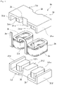
- FIG. 1 is a schematic perspective view showing a reactor of Embodiment 1.
- FIG. 2 is a plan view of a coil and a split core piece included in the reactor of Embodiment 1 as viewed in the axial direction of wound portions.
- FIG. 3 is a front view showing the reactor of Embodiment 1.
- FIG. 4 is a schematic exploded perspective view showing the reactor of Embodiment 1.
- FIG. 5 is a schematic perspective view showing a reactor of Embodiment 2.
- FIG. 6 is a schematic perspective view showing a reactor of Embodiment 3.
- a reactor includes a coil including two wound portions obtained by winding a winding wire and a magnetic core in which the wound portions are arranged.
- the magnetic core includes an inner leg portion arranged inside inner peripheries of the wound portions; a central leg portion provided between the wound portions; two outer leg portions that are provided outside outer peripheries of the wound portions and between which the inner leg portions and the central leg portion are provided; and two coupling portions between which the inner leg portions, the central leg portion, and the outer leg portions, which are arranged in parallel, are sandwiched and with which these portions are coupled.
- the above-mentioned reactor is small in size and is less likely to be saturated with magnetism.
- the details are as follows.
- the opposite magnetic flux coil as used herein refers to a coil in which two wound portions are provided such that magnetic fluxes passing through the respective wound portions flow in substantially opposite directions when an electric current is applied to the coil in a state in which the coil is assembled to the above-described specific magnetic core. That is, with the opposite magnetic flux coil, the two wound portions are arranged in parallel, and magnetic fluxes passing through the respective wound portions flow in opposite directions.
- the above-mentioned reactor is less likely to be saturated with magnetism than the above-described reactor 1 ⁇ including the O-shaped magnetic core even when a large electric current is applied. Therefore, with the above-mentioned reactor, a decrease in inductance caused by magnetic saturation is likely to be suppressed, and excellent direct-current superposition properties are realized.
- the coil included in the above-mentioned reactor is a forward magnetic flux coil as described below, the coil can be typically configured such that the number of turns in each wound portion is half the total number of turns.
- the forward magnetic flux coil as used herein refers to a coil in which two wound portions are provided such that magnetic fluxes passing through the respective wound portions flow in substantially the same directions when an electric current is applied to the coil in a state in which the coil is assembled to the above-described specific magnetic core. That is, with the forward magnetic flux coil, the two wound portions are arranged in parallel, and magnetic fluxes passing through the respective wound portions flow in a forward direction.
- the length (also referred to as “axial length” hereinafter) in the axial direction of each wound portion included in the forward magnetic flux coil is shorter than, specifically about half of, the axial length of a single wound portion in which the total number of turns is the same.
- the size of the magnetic core can be reduced to match such a coil with a short axial length. Therefore, the footprint is easily reduced by arranging the above-mentioned reactor in the horizontal layout, and the installation height is easily reduced by arranging the reactor in the vertical layout. Accordingly, the above-mentioned reactor is small in size. Furthermore, with the above-mentioned reactor, magnetic fluxes from the wound portions can flow into the central leg portion as well as the outer leg portions, and therefore, leakage flux can be reduced, and low loss is achieved.
- the magnetic core includes at least one of a composite material molded article containing magnetic powder and a resin, and a powder molded article.
- an integrally molded product constituted by a composite material molded article, or an assembly of a plurality of split core pieces constituted by at least one of a composite material molded article and a powder molded article can be used as the magnetic core, and therefore, a degree of flexibility in selection of materials constituting the magnetic core is high.
- the coil and the magnetic core are easily assembled together, and excellent manufacturability of the reactor is thus achieved.
- different winding wires are used to form the wound portions, and the coil includes a connecting portion that electrically connects end portions of the winding wires.
- a coil can be manufactured by forming wound portions separately and then connecting the wound portions, and it is easy to form the wound portions. Therefore, the reactor of the above-mentioned embodiment is small in size and is less likely to be saturated with magnetism. In addition, excellent manufacturability of the coil is achieved.
- the wound portions are connected such that magnetic fluxes passing through the wound portions flow in the same direction.
- the above-described forward magnetic flux coil is included. Therefore, the reactor is small in size as the installation height can be reduced by arranging the reactor in the vertical layout, for example. In addition, low loss is achieved.
- the magnetic core is constituted by an assembly of a pair of split core pieces, and each of the split core pieces includes one of the coupling portions, and two inner leg pieces that form portions of the inner leg portions, a central leg piece that forms a portion of the central leg portion, and two outer leg pieces that form portions of the outer leg portions, the inner leg pieces, central leg piece, and outer leg pieces rising from the coupling portion.
- the coil and the magnetic core are easily assembled together, and the number of components to be assembled is small. Therefore, the reactor of the above-mentioned embodiment is small in size and is less likely to be saturated with magnetism. In addition, excellent manufacturability of the reactor is achieved.
- a magnetic core for a reactor of the present disclosure is a magnetic core for a reactor to which a coil including two wound portions obtained by winding a winding wire is assembled, and the magnetic core includes an inner leg portion arranged inside inner peripheries of the wound portions.
- a central leg portion is arranged apart from the inner leg portions and is provided between the inner leg portions.
- Two outer leg portions are arranged apart from the inner leg portions and between which the inner leg portions and the central leg portion are provided. Two coupling portions between which the inner leg portions, the central leg portion, and the outer leg portions, which are arranged in parallel, are sandwiched and with which these portions are coupled.
- the inner leg portions can be shortened in response to the axial lengths of the wound portions being relatively short as described above.
- the central leg portion and the outer leg portions can be shortened to match the inner leg portions.
- the footprint is easily reduced by applying the above-mentioned magnetic core for a reactor with such a configuration to a reactor to be arranged in the horizontal layout, and the installation height is easily reduced by applying the magnetic core for a reactor to a reactor to be arranged in the vertical layout. Therefore, with the above-mentioned magnetic core for a reactor, a small reactor can be formed. Furthermore, with the above-mentioned magnetic core for a reactor, leakage flux can be reduced due to the central leg portion, thus making it possible to form a low-loss reactor.
- each of reactors shown in the diagrams is used as an installation surface to be arranged on a placement surface of an installation target.
- a direction in which leg portions included in a magnetic core are lined up e.g., left-right direction in FIGS. 2 and 3
- the axial direction of the leg portions e.g., vertical direction in FIG.
- a direction that is orthogonal to both the width direction and the height direction is also referred to as a “longitudinal direction”.
- FIG. 2 shows a state in which a coil 2 A shown in FIG. 1 is cut along a plane that is orthogonal to the axial direction of wound portions 2 a and 2 b .
- FIG. 3 is a front view of the reactor 1 A shown in FIG. 1 showing a side on which a connecting portion 2 j A of a coil 2 A is arranged, as viewed in a direction (left-right direction in FIG. 3 ) that is orthogonal to the direction in which the wound portions 2 a and 2 b are lined up.
- the reactor 1 A of Embodiment 1 includes a coil 2 A including two wound portions 2 a and 2 b obtained by winding a winding wire 2 w , and a magnetic core 3 in which the wound portions 2 a and 2 b are arranged.
- the magnetic core 3 of the embodiment has a specific shape.
- the magnetic core 3 has a shape obtained by further providing the above-described EE core with two magnetic legs that are provided on two sides of the middle leg such that the middle leg is provided therebetween.
- the magnetic core 3 includes five magnetic legs (inner leg portions 3 a and 3 b , a central leg portion 31 , and outer leg portions 32 and 33 ; see FIG.
- the magnetic core 3 of this embodiment is an assembly of a plurality of split core pieces 3 ⁇ and 3 ⁇ ( FIG. 4 ).
- the reactor 1 A of this embodiment is used in the vertical layout where the reactor 1 A is installed such that the axial direction of the wound portions 2 a and 2 b (or the axial direction of the inner leg portions 3 a and 3 b ) is orthogonal to the placement surface of an installation target (not shown) such as a converter case.
- the reactor 1 A of this embodiment includes, as the coil 2 A, the above-described forward magnetic flux coil in which the wound portions 2 a and 2 b are connected such that the magnetic fluxes passing through the respective wound portions 2 a and 2 b flow in the same direction.
- the coil 2 A the above-described forward magnetic flux coil in which the wound portions 2 a and 2 b are connected such that the magnetic fluxes passing through the respective wound portions 2 a and 2 b flow in the same direction.
- the coil 2 A includes tubular wound portions 2 a and 2 b obtained by spirally winding a single winding wire 2 w , and a connecting portion 2 j A that is constituted by a portion of the winding wire 2 w located between the wound portions 2 a and 2 b and electrically connects the wound portions 2 a and 2 b .
- the wound portions 2 a and 2 b are arranged side-by-side with a predetermined interval (here, the interval is greater than or equal to a width W 31 of the central leg portion 31 ( FIG. 2 )) such that their axes extend in parallel.
- the winding wire 2 w of this embodiment is a coated wire including a conductive wire made of copper or the like, and an insulating coating that is made of an insulating material such as polyamideimide and covers the outer periphery of the conductive wire.
- the winding wire 2 w is a flat wire with a rectangular cross section.
- the wound portions 2 a and 2 b of this embodiment are edgewise coils. Wire rods with various shapes such as a round wire can also be used as the winding wire 2 w .
- using a flat wire to form edgewise coils as in this embodiment makes it easier to increasing a space factor and thus reduce the size (in particular, the axial length is easily reduced), and is advantageous in that (1) the installation height of the coil 2 is easily reduced by reducing the thickness of the winding wire 2 w and (2) the end surfaces of the coil 2 A (upper surface and lower surface in FIG. 4 ) is easily made substantially flat, in the case of the vertical layout.
- the wound portions 2 a and 2 b of this embodiment have the same shape, and are formed in a quadrilateral tube shape in which the end surfaces have a rectangular shape with round corners.
- the shape of the wound portions 2 a and 2 b can be selected as appropriate, and an example thereof is a cylindrical shape.
- the wound portions 2 a and 2 b of this embodiment are configured such that the winding directions and the numbers of turns are the same, and are connected to each other via the connecting portion 2 j A such that magnetic fluxes passing through the respective wound portions 2 a and 2 b flow in the same direction when an electric current is applied to the coil 2 A.
- Such a coil 2 A can be considered to include two wound portions 2 a and 2 b obtained by dividing one wound portion in which the total number of turns is the same, and the axial length of the coil 2 A is smaller than that of a coil (referred to as a “single coil” hereinafter) including a single wound portion in which the total number of turns is the same. Therefore, when the reactor 1 A is vertically installed, the installation height is lower compared with a case of using the reactor including the single coil. It should be noted that the winding directions and the numbers of turns in the wound portions 2 a and 2 b can be selected as appropriate.
- Winding the wire in the same direction as in this embodiment makes it easy to form the wound portions 2 a and 2 b , and excellent manufacturability of the coil 2 A is thus achieved.
- Setting the numbers of turns to be the same as in this embodiment makes it possible to make the axial length of the coil 2 A the shortest, thus making it possible to reduce the installation height of the reactor 1 A arranged in the vertical layout.
- the connecting portion 2 j A of this embodiment is formed by bending the winding wire 2 w , which is a single continuous wire forming the wound portions 2 a and 2 b , as appropriate at a portion located between the wound portions 2 a and 2 b .
- the connecting portion 2 j A as used herein has a portion bent into a reverse J-shape (including two flatwise bent portions and two edgewise bent portions) so as to connect the lower end surface of one of the wound portions, namely the wound portion 2 a , and the upper end surface of the other of the wound portions, namely the wound portion 2 b .
- the connecting portion 2 j A as used herein has a size with which a portion thereof protrudes from a surface (here, the upper surface of a coupling portion 34 located on the upper side) that is on a side opposite to the installation surface of the magnetic core 3 (here, the lower surface of a coupling portion 35 located on the lower side) when the reactor 1 A is vertically installed as shown in FIG. 3 .
- the shape and size of the connecting portion 2 j A can be selected as appropriate (see Embodiments 2 and 3, which will be described later).
- the size of the connecting portion 2 j A in the height direction is adjusted in accordance with the axial lengths of the wound portions 2 a and 2 b , for example, and the size of the connecting portion 2 j A in the width direction is adjusted in accordance with the width W 31 of the central leg portion 31 , for example. Allowing a portion of the connecting portion 2 j A to protrude from the magnetic core 3 as in this embodiment makes it easy to form the coil 2 A, and excellent manufacturability is thus achieved.
- the installation height of the reactor 1 A arranged in the vertical layout can be further reduced by bending the connecting portion 2 j A such that this protruding portion overlaps the upper surface of the coupling portion 34 after the coil 2 A and the magnetic core 3 are assembled together.
- the end portions of the winding wire 2 w that are continuous with the wound portions 2 a and 2 b are used as portions to be connected to external devices such as a power source.
- external devices such as a power source.
- the case where the end portions of the winding wire 2 w are guided upward so as to move away from the wound portions 2 a and 2 b , and are arranged adjacent to the connecting portion 2 j A is shown as an example, but the guiding direction, guiding length, and the like can be changed as appropriate.
- the coil 2 A can include a resin molded portion (not shown) that covers at least a portion of the outer peripheries of the wound portions 2 a and 2 b .
- the resin molded portion can be configured to cover the substantial entirety of the inside and outside of the wound portions 2 a and 2 b , or cover the wound portions 2 a and 2 b while at least a portion of the inner peripheral surfaces, outer peripheral surfaces, and end surfaces of the wound portions 2 a and 2 b is not covered and is exposed, for example.
- an exposed portion (which will be described later) of the wound portions 2 a and 2 b that is not covered with the magnetic core 3 is also exposed from the resin molded portion, it is easy to enhance heat dissipation properties.
- Arranging the resin molded portion between the wound portions 2 a and 2 b and the magnetic core 3 makes it possible to enhance electric insulation between the coil 2 A and the magnetic core 3 . It should be noted that, when the resin molded portion is not provided, using the above-described coated wire as the winding wire 2 w makes it possible to enhance electric insulation between the coil 2 A and the magnetic core 3 .
- thermoplastic resins such as thermoplastic resins and thermosetting resins.
- thermoplastic resins include polyphenylene sulfide (PPS) resin, polytetrafluoroethylene (PTFE) resin, a liquid crystal polymer (LCP), polyamide (PA) resin (such as nylon 6 or nylon 66), polybutylene terephthalate (PBT) resin, and acrylonitrile-butadiene-styrene (ABS) resin.
- thermosetting resins include unsaturated polyester resin, epoxy resin, urethane resin, and silicone resin.
- Nonmagnetic nonmetallic powder made of alumina, silica, or the like can be added to the insulating resin. In this case, heat dissipation properties, electric insulation, and the like can be enhanced.
- the magnetic core 3 of this embodiment is used in the reactor 1 A in which the coil 2 A including the two wound portions 2 a and 2 b obtained by winding the winding wire 2 w is provided.
- This magnetic core 3 includes the inner leg portions 3 a and 3 b that are respectively arranged inside the inner peripheries of the wound portions 2 a and 2 b , the central leg portion 31 that is arranged between the wound portions 2 a and 2 b , the two outer leg portions 32 and 33 between which the two inner leg portions 3 a and 3 b and the central leg portion 31 are provided, and the two coupling portions 34 and 35 between which the two inner leg portions 3 a and 3 b , the central leg portion 31 , and the two outer leg portions 32 and 33 , which are arranged in parallel, are sandwiched and with which these portions are coupled.
- the central leg portion 31 is arranged apart from the inner leg portions 3 a and 3 b .
- the outer leg portions 32 and 33 are arranged apart from the inner leg portions 3 a and 3 b , respectively ( FIGS. 2 and 4 ).
- the gaps between the portions formed by arranging these portions as described above are used as portions at which the wound portions 2 a and 2 b are to be arranged. Specifically, as shown in FIG.
- one of the wound portions namely the wound portion 2 a
- one of the wound portions is arranged to be fit in a gap (width Wc) between the central leg portion 31 and one of the inner leg portions, namely the inner leg portion 3 a
- one of the outer leg portions namely the outer leg portion 32 .
- the other of the wound portions namely the wound portion 2 b
- the other of the outer leg portions namely the outer leg portion 33 .
- the outer leg portions 32 and 33 are respectively provided outside the outer peripheries of the wound portions 2 a and 2 b such that the group of the leg portions including the inner leg portion 3 a , the central leg portion 31 , and the inner leg portion 3 b , which are lined up in this order from the outer leg portion 32 side to the outer leg portion 33 side, is provided therebetween.
- the magnetic core 3 can be formed of a composite material molded article containing magnetic powder and a resin.
- particles of the magnetic powder include particles made of a soft magnetic metal or a soft magnetic nonmetal, and coated particles obtained by providing an insulating coating made of a phosphate or the like on the outer peripheries of the particles made of a soft magnetic metal.
- the soft magnetic metal include iron group metals such as pure iron and iron alloys (e.g., Fe—Si alloy and Fe—Ni alloy).
- An example of the soft magnetic nonmetal is ferrite.
- the content of the magnetic powder in the composite material is 30 vol % or more and 80 vol % or less, and the content of the resin is 10 vol % or more and 70 vol % or less.
- the content of the magnetic powder can be set to 50 vol % or more, 55 vol % or more, or 60 vol % or more, from the viewpoint of enhancing saturation magnetic flux density and heat dissipation properties.
- the content of the magnetic powder can be set to 75 vol % or less, or 70 vol % or less, from the viewpoint of enhancing the fluidity during the manufacturing process.
- thermosetting resins and thermoplastic resins which were described in the above-described section of “Resin molded portion”, as well as cold setting resins and low-temperature curing resins.
- Bulk molding compounds (BMCs) obtained by mixing calcium carbonate or glass fibers to unsaturated polyester, millable-type silicone rubber, millable-type urethane rubber, and the like can also be used.
- the composite material may also contain nonmagnetic nonmetallic powder made of alumina, silica, or the like in addition to the magnetic powder and the resin.
- the content of the nonmagnetic nonmetallic powder may be 0.2 mass % or more and 20 mass % or less, 0.3 mass % or more and 15 mass % or less, and 0.5 mass % or more and 10 mass % or less.
- the composite material molded article can be manufactured using an appropriate molding method such as injection molding or a cast molding.
- an integrally molded magnetic core 3 can be manufactured by placing the coil 2 A in a mold having an appropriate shape and fill the inside and the outside of the coil 2 A with a fluidized composite material.
- a mold having an appropriate shape makes it possible to manufacture a split core piece formed of a composite material molded article.
- the composite material molded article can also be easily molded into a complex shape, and thus excellent manufacturability is achieved.
- the magnetic core 3 can be formed of a powder molded article containing magnetic powder.
- the powder molded article include those obtained by molding mixed powder containing magnetic powder and a binder into a predetermined shape through compression molding, and those obtained by being further subject to heat treatment after being molded.
- a resin can be used as the binder, and the content thereof may be about 30 vol % or less.
- the binder may be decomposed or be thermally denatured through heat treatment. Using a mold having an appropriate shape makes it possible to manufacture a split core piece formed of the powder molded article. With the powder molded article, the content of the magnetic powder can be increased compared with a case where the composite material molded article is used, and thus a magnetic core having a high saturation magnetic flux density is easily formed.
- the magnetic core 3 can be formed of a laminate obtained by laminating soft magnetic plates such as silicon steel plates, or a sintered body such as a ferrite core.
- the magnetic core 3 can be provided with a gap material or an air gap.
- the gap material include materials made of a nonmagnetic material such as alumina, and materials that are made of a mixture of a magnetic material and a nonmagnetic material and have a low relative permeability than molded articles such as split core pieces.
- a magnetic gap such as a gap material and an air gap can be omitted or reduced. In this case, loss caused by leakage flux at the magnetic gap portion is easily reduced, and the coil 2 A and the magnetic core 3 can be arranged in proximity to each other. Therefore, the size is easily reduced.
- FIG. 2 is similar to the lateral cross section obtained by cutting the magnetic core 3 , which is formed of an integrally molded product, along a plane that is orthogonal to the axial direction of the group of the leg portions including the central leg portion 31 and the like.
- the magnetic core 3 of this embodiment is formed by attaching a pair of split core pieces 3 a and 3 b .
- One of the split core pieces includes one of the coupling portions, namely the coupling portion 34 , two inner leg pieces 3 ⁇ a and 3 ⁇ b that rise from the coupling portion 34 and form portions of the inner leg portions 3 a and 3 b , a central leg piece 31 ⁇ that forms a portion of the central leg portion 31 , and two outer leg pieces 32 ⁇ and 33 ⁇ that form portions of the outer leg portions 32 and 33 .
- the other of the split core pieces includes the other of the coupling portions, namely the coupling portion 35 , two inner leg pieces 3 ⁇ a and 3 ⁇ b that rise from the coupling portion 35 and form the other portions of the inner leg portions 3 a and 3 b , a central leg piece 31 ⁇ that forms the other portion of the central leg portion 31 , and two outer leg pieces 32 ⁇ and 33 ⁇ that form the other portions of the outer leg portions 32 and 33 .
- each of the shapes of the end surfaces of the split core pieces 3 ⁇ and 3 ⁇ is symmetrical about a central line Lw in the width direction and a central line L 1 in the longitudinal direction as shown in FIG.
- the split core pieces 3 ⁇ and 3 ⁇ are formed to have the same shape, the same size, and a symmetrical shape as described above, excellent manufacturability of the split core pieces is achieved.
- an assembly of the pair of split core pieces 3 ⁇ and 3 ⁇ is used as the magnetic core 3 as in this embodiment, the number of assembling steps can be reduced, and thus excellent workability for assembly of the reactor 1 A is achieved.
- the magnetic core 3 may have a configuration in which the split core pieces are made of different materials (e.g., a configuration in which a split core piece formed of a composite material molded article and a split core piece formed of a powder molded article are included) or a configuration in which all the split core pieces are made of the same material.
- the inner leg portions 3 a and 3 b of this embodiment have the same shape and size as shown in FIGS. 1, 2, and 4 .
- the inner leg portions 3 a and 3 b of this embodiment have a rectangular parallelepiped shape in which the shape of the lateral cross section (which is equal to the shapes of the end surfaces of the inner leg pieces 3 ⁇ a , 3 ⁇ b , 3 ⁇ a , and 3 ⁇ b ) taken along a plane orthogonal to the axial direction of the inner leg portions 3 a and 3 b (which typically extends in substantially the same direction as the axial direction of the wound portions 2 a and 2 b ) corresponds to the inner peripheral shapes of the wound portions 2 a and 2 b .
- the shapes and sizes of the inner leg portions 3 a and 3 b can be selected as appropriate depending on the shapes and sizes of the wound portions 2 a and 2 b as long as the lateral cross sections have a predetermined area for a magnetic path.
- the outer peripheral shapes of the inner leg portions 3 a and 3 b are similar to the inner peripheral shapes of the wound portions 2 a and 2 b as in this embodiment, it is easy to bring the magnetic core 3 and the coil 2 A close to each other and assemble them together, thus making it possible to reduce the size.
- the central leg portion 31 of this embodiment has a rectangular parallelepiped shape as shown in FIGS. 2 to 4 , and the shape of the lateral cross section (which is equal to the shapes of the end surfaces of the central leg pieces 31 ⁇ and 31 ⁇ ) taken along a plane orthogonal to the axial direction of the central leg portion 31 (which typically extends substantially in parallel with the axial direction of the wound portions 2 a and 2 b ) has a rectangular shape.
- the size (e.g., lateral cross-sectional area) of the central leg portion 31 is adjusted so as to have a predetermined cross-sectional area for a magnetic path.
- the central leg portion 31 When the cross-sectional area for a magnetic path of the central leg portion 31 is 50% or more, 60% or more, or 70% or more of the lateral cross-sectional area of one inner leg portion ( 3 a or 3 b ), it is expected that the central leg portion 31 can function as a magnetic path.
- the lateral cross-sectional area of the central leg portion 31 is substantially the same as the cross-sectional area of one inner leg portion ( 3 a or 3 b ).
- the central leg portion 31 has a width W 31 and a length L 31 that are substantially the same as widths and the lengths L 3a and L 3b of the inner leg portions 3 a and 3 b , respectively.
- the outer leg portions 32 and 33 of this embodiment have the same shape and size as shown in FIGS. 2 to 4 .
- the shape of the lateral cross section (which is equal to the shapes of the end surfaces of the outer leg pieces 32 ⁇ , 32 ⁇ , 33 ⁇ , and 33 ⁇ ) taken along a plane orthogonal to the axial direction of the outer leg portions 32 and 33 (which typically extends substantially in parallel with the axial direction of the wound portions 2 a and 2 b ) has a rectangular shape.
- the shapes and sizes of the outer leg portions 32 and 33 can be selected as appropriate depending on the shapes and sizes of the wound portions 2 a and 2 b as long as the lateral cross sections have a predetermined area for a magnetic path.
- the respective areas of the lateral cross sections of the outer leg portions 32 and 33 are substantially the same as half of the area of the cross section of one inner leg portion ( 3 a or 3 b ). Moreover, in this embodiment, the respective widths of the outer leg portions 32 and 33 are smaller than the width of one inner leg portion, and lengths L 32 and L 33 of the outer leg portions 32 and 33 are longer than the lengths L 3a and L 3b of the inner leg portions 3 a and 3 b . Therefore, the two sides in the longitudinal direction of the outer leg portions 32 and 33 protrude from the group of the leg portions including the inner leg portions 3 a and 3 b and the central leg portion 31 .
- the coupling portions 34 and 35 of this embodiment are formed in a thin rectangular parallelepiped shape and have the same shape and size.
- One surface of the coupling portions 34 and 35 (the lower surface of the coupling portion 35 in FIGS. 1 and 3 ) serves as an installation surface to be arranged on the placement surface of an installation target.
- the coupling portions 34 and 35 have widths W 34 and W 35 and lengths L 34 and L 35 with which the group of leg portions, namely the outer leg portion 32 , the inner leg portion 3 a , the central leg portion 31 , the inner leg portion 3 b , and the outer leg portion 33 , which are arranged side-by-side with intervals, can be provided therebetween.
- the central leg portion 31 is provided at the central portions in the width direction and the longitudinal direction of the coupling portions 34 and 35 , and a set of the inner leg portion 3 a and the outer leg portion 32 , and a set of the inner leg portion 3 b and the outer leg portion 33 are respectively provided on the two sides of the central leg portion 31 .
- cutout portions 38 formed by cutting out trapezoidal portions are provided at the central portion in the width direction, and the lengths vary depending on the portions.
- the two edges in the width direction correspond to the edges of the lateral surfaces of the outer leg portions 32 and 33 that are provided on the two sides in the width direction, and the lengths L 34 and L 35 of portions provided on the two sides in the width direction of the respective coupling portions 34 and 35 are equal to the lengths L 32 and L 33 of the outer leg portions 32 and 33 .
- the lengths of the central portions in the width direction of the coupling portions 34 and 35 namely the lengths of the regions provided with the central leg portion 31 , are equal to the lengths L 3 , and Lab of the inner leg portions 3 a and 3 b due to the above-described cutout portions 38 being formed.
- the regions provided on the two sides in the length direction of the inner leg portions 3 a and 3 b are used as the portions on which the wound portions 2 a and 2 b are arranged ( FIG. 2 ).
- the total length of each region corresponds to a difference between the length L 34 or L 35 and the length L 3a or L 3b , which are described above.
- linear gaps are provided between the inner leg portion 3 a and the central leg portion 31 , between the inner leg portion 3 b and the central leg portion 31 , between the inner leg portion 3 a and the outer leg portions 32 , which are adjacent to each other, and between the inner leg portion 3 b and the outer leg portions 33 , which are adjacent to each other.
- the widths W 34 and W 35 of the coupling portions 34 and 35 are adjusted such that widths Wc and Ws of these gaps are slightly larger than the widths of the wound portions 2 a and 2 b . This makes it possible to enhance insulation between the coil 2 A and the magnetic core 3 , and also makes it easy to assemble the coil 2 A and the split core pieces 3 ⁇ and 3 ⁇ together.
- the lengths L 34 and L 35 of the coupling portions 34 and 35 are adjusted such that when the coil 2 A is assembled to the magnetic core 3 , surfaces (upper and lower surfaces in FIG. 2 ) arranged on the two sides in the longitudinal direction out of the outer peripheral surfaces of the wound portions 2 a and 2 b are not covered with the magnetic core 3 and exposed ( FIGS. 1 and 3 ), and the other regions are substantially covered with the magnetic core 3 .
- the lengths L 34 and L 35 and the lengths L 3a , L 3b , and L 31 are adjusted such that the portions of the wound portions 2 a and 2 b exposed from the magnetic core 3 are substantially flush with the end surfaces (upper and lower surfaces in FIG. 2 ) arranged on the two sides in the longitudinal direction of the coupling portions 34 and 35 .
- the exposed portions of the wound portions 2 a and 2 b can be used as heat dissipation surfaces while the reactor 1 A is being used, for example.
- the reactor 1 A of Embodiment 1 can be used in constituent components of various types of converters such as vehicle-mounted converters (typically DC-DC converters) to be mounted in vehicles including hybrid cars, plug-in hybrid cars, electric cars, fuel cell cars, and the like, and converters for an air conditioner, and constituent components of power conversion devices.
- vehicle-mounted converters typically DC-DC converters
- the reactor 1 A of Embodiment 1 can be used in cases where large inductance is required, the number of turns is relatively large, and a low height is in demand.
- the magnetic core 3 of this embodiment can be used as a constituent element of the reactor 1 A or the like.
- the reactor 1 A of Embodiment 1 even when the total number of turns in the coil 2 A is relatively large, a forward magnetic flux coil including separate wound portions 2 a and 2 b is used, thus making it possible to make the axial length of the coil 2 A shorter than that of a single coil in which the total number of turns is the same.
- Arranging, in the vertical layout, the reactor 1 A including such a forward magnetic flux coil and the magnetic core 3 having a specific shape makes it possible to reduce the installation height. From this viewpoint, the reactor 1 A of Embodiment 1 is small in size.
- the installation height of the reactor 1 A can be further reduced.
- the magnetic core 3 for a reactor of this embodiment contributes to a reduction in height when used in the reactor 1 A, which includes the above-mentioned forward magnetic flux coil and is arranged in the vertical layout, for example.
- the reactor 1 A of Embodiment 1 includes the magnetic core 3 including the central leg portion 31 in addition to the inner leg portions 3 a and 3 b and the outer leg portions 32 and 33 , magnetic fluxes from the wound portions 2 a and 2 b are less likely to leak to the outside of the magnetic core 3 . Therefore, the reactor 1 A of Embodiment 1 is a low-loss reactor.
- the magnetic core 3 for a reactor of this embodiment can reduce leakage flux and contributes to a reduction in loss when used in the reactor 1 A including the above-mentioned forward magnetic flux coil.
- the outer peripheral surfaces of the wound portions 2 a and 2 b are partially flush with the outer surface of the magnetic core 3 , and the number of portions of the coil 2 A that protrude from the magnetic core 3 is small.
- the above-mentioned protruding portions are substantially only the two end portions of the winding wire 2 w and a portion of the connecting portion 2 j A, and the footprint of the reactor 1 A is substantially equal to the area of the installation surface (the lower surface of the coupling portion 35 ) of the magnetic core 3 .
- the reactor 1 A is small in size since the footprint is small.
- portions of the wound portions 2 a and 2 b are not covered with the magnetic core 3 and are exposed, heat dissipation properties can be enhanced.
- the magnetic core 3 includes portions at which the wound portions 2 a and 2 b are arranged, and thus positioning of the coil 2 A and the magnetic core 3 can be easily performed.
- an assembly of the pair of split core pieces 3 ⁇ and 3 ⁇ is used as the magnetic core 3 , the coil 2 A and the magnetic core 3 can be easily assembled together. Therefore, excellent manufacturability of the reactor 1 A is achieved.
- the magnetic core 3 is constituted by the assembly of the split core pieces 3 ⁇ and 3 ⁇ having the same shape, and the shape of the split core pieces 3 ⁇ and 3 ⁇ is symmetrical and simple, excellent manufacturability of the magnetic core 3 is achieved.
- the magnetic core 3 is provided with the cutout portions 38 , the weight of the magnetic core 3 can be reduced, and thus the weight of the reactor 1 A can be reduced.
- the cutout portions 38 are formed at positions through which magnetic fluxes from the wound portions 2 a and 2 b barely pass, thus making it possible to ensure a predetermined area for a magnetic path even when portions of the magnetic core 3 are removed.
- the basic configurations of a reactor 1 B of Embodiment 2 shown in FIG. 5 and a rector 1 C of Embodiment 3 shown in FIG. 6 are the same as that of the above-described rector 1 A of Embodiment 1.
- the structures of connecting portions 2 j B and 2 j C of coils 2 B and 2 C provided in the reactor 1 B and 1 C are different from that of the connecting portions 2 j A.
- the coil 2 B included in the reactor 1 B of Embodiment 2 is different from the above-described coil 2 A in that the coil 2 B includes two winding wires 2 wa and 2 wb .
- Wound portions 2 a and 2 b included in the coil 2 B respectively include the winding wires 2 wa and 2 wb , which are different from each other.
- the coil 2 B includes a connecting portion 2 j B that electrically connects the end portions of the winding wires 2 wa and 2 wb.
- one end portion is used as a portion to be connected to an external device, and the other end portion is used as a portion for formation of the connecting portion 2 j B.
- the other end portion of one of the winding wires namely the winding wire 2 wa
- the other end portion of one of the winding wires includes a portion extending upward, a portion extending toward the other of the wound portions, namely the wound portion 2 b , and portions bent to form these two portions, and is formed in a reverse L-shape.
- the other end portion of the other of the winding wires, namely the winding wire 2 wb includes a portion extending upward as in the one end portion.
- the connecting portion 2 j B includes a portion where the leading ends of the other end portions of the winding wires 2 wa and 2 wb are joined together.
- a direct joining process such as welding (e.g., TIG welding, laser welding, or resistance welding), crimping, cold welding, or vibration welding and an indirect joining process in which solder, a wax material, or the like is used can be used as the joining process.
- the joining process may be performed before or after the coil 2 B and the magnetic core 3 are assembled together.
- the above-described joining process can be performed after the coil 2 B and one of the split core pieces are attached to each other.
- a forward magnetic flux coil is used as the coil 2 B, and the magnetic core 3 having a specific shape is included, thus making it possible to reduce the installation height when the reactor 1 B is arranged in the vertical layout.
- leakage flux can be reduced due to the magnetic core 3 , and low loss is achieved.
- the winding wires 2 wa and 2 wb which are different from each other, are used to form the wound portions 2 a and 2 b . Therefore, the wound portions 2 a and 2 b are easily formed, and excellent manufacturability of the coil 2 B is achieved.
- the other end portions of the winding wires 2 wa and 2 wb can be bent or folded back in a state in which adjacent wound portions are not present, and the connecting portion 2 j B is thus easily formed, excellent manufacturability of the coil 2 B is achieved.
- adjusting the lengths of the other end portions of the winding wires 2 wa and 2 wb constituting the connecting portions 2 j B makes it possible to adjust the interval between the wound portions 2 a and 2 b with high accuracy, and perform adjustment corresponding to the size (including manufacturing error) of the magnetic core 3 to be assembled. Therefore, excellent accuracy of dimensions can be achieved in the reactor 1 B.
- the coil 2 C included in the rector 1 C of Embodiment 3 is different from the above-described coil 2 A in that the connecting portion 2 j C does not protrude from the magnetic core 3 .
- the connecting portion 2 j C of this embodiment includes a portion that is bent into an S-shape so as to extend from the lower end surface of one of the wound portions, namely the wound portion 2 a , to the upper end surface of the other of the wound portions, namely the wound portion 2 b .
- the height of the connecting portion 2 j C is substantially the same as the heights H 2 of the wound portions 2 a and 2 b.
- a forward magnetic flux coil is used as the coil 2 C, and the magnetic core 3 having a specific shape is included, thus making it possible to reduce the installation height when the reactor 1 C is arranged in the vertical layout.
- leakage flux can be reduced due to the magnetic core 3 , and low loss is achieved.
- the connecting portion 2 j C does not substantially protrude from both the wound portions 2 a and 2 b and the magnetic core 3 in the height direction, and therefore, the installation height is lower.
- Adjusting the position at which the connecting portion 2 j C is formed, the shape of the connecting portions 2 j C, and the like as described above makes it possible to form the reactor 1 C with which a lower installation height can be achieved. If the bending positions and the lengths of the extra portions at the other end portions of the winding wires 2 wa and 2 wb , which were descried in the above-described Embodiment 2, are adjusted, the connecting portion 2 j B can be formed so as not to protrude from the magnetic core 3 in the height direction of the reactor 1 B.
- Embodiments 1 to 3 the cases where all of the coils 2 A to 2 C are forward magnetic flux coils were described.
- An opposite magnetic flux coil in which magnetic fluxes passing through the wound portions 2 a and 2 b flow in opposite directions when an electric current is applied to the coil 2 A or the like can be used instead of the forward magnetic flux coil.
- a single winding wire 2 w is used as in Embodiments 1 and 3 to form an opposite magnetic flux coil, a portion of the winding wire 2 w that connects the wound portion 2 a and 2 b may be folded back such that magnetic fluxes passing through the wound portions 2 a and 2 b flow in opposite directions (see FIG. 1 and the like in JP 2016-122760A).
- Embodiment 2 When two winding wires 2 wa and 2 wb are used as in Embodiment 2 to form an opposite magnetic flux coil, it is sufficient that the winding wires 2 wa and 2 wb are wound in the same direction in the wound portion 2 a and 2 b , and the other end portion of one of the winding wires is folded back and the other end portions are joined together such that magnetic fluxes passing through the wound portions 2 a and 2 b flow in opposite directions.
- known opposite magnetic flux coils having various shapes can be used.
- the reactor of Embodiment 4 including an opposite magnetic flux coil particularly includes the magnetic core 3 including the central leg portion 31 in addition to the inner leg portions 3 a and 3 b and the outer leg portions 32 and 33 , thus making it possible to flow magnetic fluxes from the wound portions 2 a and 2 b in the central leg portion 31 . Therefore, even when a larger electric current is applied, magnetic flux saturation is less likely to occur, and inductance is less likely to decrease.
- a sensor for measuring a physical quantity in the reactor, such as a temperature sensor, a current sensor, a voltage sensor, or a magnetic flux sensor is provided.
- Heat dissipation plates are provided at the exposed portions of the wound portions 2 a and 2 b.
- An insulating intervention member such as a bobbin is provided instead of the resin molded portion.
- Heat welded resin portions (not shown) that joins the adjacent turns included in the wound portions 2 a and 2 b are provided instead of the resin molded portion or in addition to the resin molded portion.
- a case made of a metal such as aluminum or an aluminum alloy
- the assembly including the coil 2 A and the like and the magnetic core 3 is to be stored.
- a heat dissipation layer is provided between the assembly and the inner bottom surface of the case.
- Specific materials of the heat dissipation layer include those containing a filler (nonmagnetic nonmetallic powder made of alumina or the like) having excellent heat dissipation properties and resin (optionally an adhesive).
- a horizontal layout is also possible.
- configurations can be employed in which the exposed portions of the wound portions 2 a and 2 b are used as an installation surface, and one of the outer leg portions is used as an installation surface.
Landscapes
- Engineering & Computer Science (AREA)
- Power Engineering (AREA)
- Coils Of Transformers For General Uses (AREA)
Abstract
Description
Coil
Outline
Claims (16)
Applications Claiming Priority (4)
| Application Number | Priority Date | Filing Date | Title |
|---|---|---|---|
| JP2016-184616 | 2016-09-21 | ||
| JPJP2016-184616 | 2016-09-21 | ||
| JP2016184616A JP6635306B2 (en) | 2016-09-21 | 2016-09-21 | Magnetic core for reactors and reactors |
| PCT/JP2017/031942 WO2018056049A1 (en) | 2016-09-21 | 2017-09-05 | Reactor, and magnetic core for reactor |
Publications (2)
| Publication Number | Publication Date |
|---|---|
| US20190237237A1 US20190237237A1 (en) | 2019-08-01 |
| US11417455B2 true US11417455B2 (en) | 2022-08-16 |
Family
ID=61690912
Family Applications (1)
| Application Number | Title | Priority Date | Filing Date |
|---|---|---|---|
| US16/335,100 Active 2039-10-03 US11417455B2 (en) | 2016-09-21 | 2017-09-05 | Reactor and magnetic core for reactor |
Country Status (4)
| Country | Link |
|---|---|
| US (1) | US11417455B2 (en) |
| JP (1) | JP6635306B2 (en) |
| CN (1) | CN109716459B (en) |
| WO (1) | WO2018056049A1 (en) |
Families Citing this family (5)
| Publication number | Priority date | Publication date | Assignee | Title |
|---|---|---|---|---|
| JP7117905B2 (en) * | 2018-06-14 | 2022-08-15 | 株式会社タムラ製作所 | Reactor |
| JP6734328B2 (en) | 2018-08-06 | 2020-08-05 | 株式会社京三製作所 | Reactor |
| JP2020053625A (en) * | 2018-09-28 | 2020-04-02 | 株式会社オートネットワーク技術研究所 | Coil device and electrical junction box |
| JP7367584B2 (en) * | 2020-03-27 | 2023-10-24 | 株式会社オートネットワーク技術研究所 | Reactors, converters, and power conversion equipment |
| JP7771762B2 (en) * | 2022-01-12 | 2025-11-18 | 株式会社村田製作所 | reactor |
Citations (16)
| Publication number | Priority date | Publication date | Assignee | Title |
|---|---|---|---|---|
| US5053738A (en) * | 1989-11-27 | 1991-10-01 | Tokyo Electric Co., Ltd. | Magnetic leakage transformer |
| JPH07263262A (en) | 1994-03-25 | 1995-10-13 | Sony Corp | Combined AC reactor |
| JPH08107023A (en) | 1994-10-03 | 1996-04-23 | Nemic Lambda Kk | Inductance element |
| JP2001093737A (en) | 1999-09-24 | 2001-04-06 | Matsushita Electric Ind Co Ltd | choke coil |
| US20050068149A1 (en) * | 2003-09-25 | 2005-03-31 | Tadayuki Fushimi | Leakage transformer |
| US6876161B2 (en) * | 2003-05-28 | 2005-04-05 | Yu-Lin Chung | Transformer for cathode tube inverter |
| US20050073385A1 (en) * | 2003-10-02 | 2005-04-07 | Chen-Feng Wu | Transformer |
| US20070091519A1 (en) * | 2005-10-26 | 2007-04-26 | Matsushita Electric Works, Ltd. | Power supply system |
| US20080088403A1 (en) * | 2005-09-05 | 2008-04-17 | Minebea Co., Ltd. | Inverter Transformer |
| US20080211616A1 (en) * | 2007-02-19 | 2008-09-04 | Minebea Co., Ltd. | Inverter transformer having bobbin with protected terminal pins |
| US7446640B2 (en) * | 2004-09-01 | 2008-11-04 | Sumida Corporation | Leakage transformer |
| US7612640B2 (en) * | 2006-07-26 | 2009-11-03 | Sumida Corporation | Magnetic element |
| US8242870B1 (en) * | 2009-04-13 | 2012-08-14 | Universal Lighting Technologies, Inc. | Magnetic component with a notched magnetic core structure |
| WO2015068265A1 (en) | 2013-11-08 | 2015-05-14 | 三菱電機株式会社 | Electromagnetic induction apparatus |
| JP2016122760A (en) | 2014-12-25 | 2016-07-07 | 株式会社オートネットワーク技術研究所 | Reactor |
| US9721716B1 (en) * | 2010-02-26 | 2017-08-01 | Universal Lighting Technologies, Inc. | Magnetic component having a core structure with curved openings |
Family Cites Families (11)
| Publication number | Priority date | Publication date | Assignee | Title |
|---|---|---|---|---|
| US5243313A (en) * | 1992-09-16 | 1993-09-07 | Westinghouse Electric Corp. | Tractive magnet with asymmetric permanent air gap |
| JP2000173840A (en) * | 1998-12-10 | 2000-06-23 | Toyota Autom Loom Works Ltd | Coil unit and transformer |
| JP2005294860A (en) * | 2005-05-27 | 2005-10-20 | Tdk Corp | Ferrite core |
| DE602006019471D1 (en) * | 2005-10-10 | 2011-02-17 | Texas Instr Cork Ltd | POWER CONVERTER |
| US10759007B2 (en) * | 2013-03-14 | 2020-09-01 | Bwxt Mpower, Inc. | Spacer grid welding fixture |
| KR101477393B1 (en) * | 2013-03-14 | 2015-01-06 | 삼성전기주식회사 | Coil component and electronic device having the same |
| US9882506B2 (en) * | 2013-03-29 | 2018-01-30 | Philips Lighting Holding B.V. | Multiple inductive component |
| CN203588793U (en) * | 2013-10-17 | 2014-05-07 | 江苏斯菲尔电气股份有限公司 | Frameless electric reactor |
| CN105097209B (en) * | 2014-04-25 | 2018-06-26 | 台达电子企业管理(上海)有限公司 | Magnetic element |
| CN204144029U (en) * | 2014-10-21 | 2015-02-04 | 重庆路之生科技有限责任公司 | Reactor device |
| CN204229994U (en) * | 2014-11-05 | 2015-03-25 | 江苏上能新特变压器有限公司 | The powder core core of reactor of air-gap-free |
-
2016
- 2016-09-21 JP JP2016184616A patent/JP6635306B2/en active Active
-
2017
- 2017-09-05 CN CN201780057647.XA patent/CN109716459B/en active Active
- 2017-09-05 WO PCT/JP2017/031942 patent/WO2018056049A1/en not_active Ceased
- 2017-09-05 US US16/335,100 patent/US11417455B2/en active Active
Patent Citations (17)
| Publication number | Priority date | Publication date | Assignee | Title |
|---|---|---|---|---|
| US5053738A (en) * | 1989-11-27 | 1991-10-01 | Tokyo Electric Co., Ltd. | Magnetic leakage transformer |
| JPH07263262A (en) | 1994-03-25 | 1995-10-13 | Sony Corp | Combined AC reactor |
| JPH08107023A (en) | 1994-10-03 | 1996-04-23 | Nemic Lambda Kk | Inductance element |
| JP2001093737A (en) | 1999-09-24 | 2001-04-06 | Matsushita Electric Ind Co Ltd | choke coil |
| US6876161B2 (en) * | 2003-05-28 | 2005-04-05 | Yu-Lin Chung | Transformer for cathode tube inverter |
| US20050068149A1 (en) * | 2003-09-25 | 2005-03-31 | Tadayuki Fushimi | Leakage transformer |
| US20050073385A1 (en) * | 2003-10-02 | 2005-04-07 | Chen-Feng Wu | Transformer |
| US7446640B2 (en) * | 2004-09-01 | 2008-11-04 | Sumida Corporation | Leakage transformer |
| US20080088403A1 (en) * | 2005-09-05 | 2008-04-17 | Minebea Co., Ltd. | Inverter Transformer |
| US7456719B2 (en) * | 2005-09-05 | 2008-11-25 | Minebea Co., Ltd. | Inverter transformer |
| US20070091519A1 (en) * | 2005-10-26 | 2007-04-26 | Matsushita Electric Works, Ltd. | Power supply system |
| US7612640B2 (en) * | 2006-07-26 | 2009-11-03 | Sumida Corporation | Magnetic element |
| US20080211616A1 (en) * | 2007-02-19 | 2008-09-04 | Minebea Co., Ltd. | Inverter transformer having bobbin with protected terminal pins |
| US8242870B1 (en) * | 2009-04-13 | 2012-08-14 | Universal Lighting Technologies, Inc. | Magnetic component with a notched magnetic core structure |
| US9721716B1 (en) * | 2010-02-26 | 2017-08-01 | Universal Lighting Technologies, Inc. | Magnetic component having a core structure with curved openings |
| WO2015068265A1 (en) | 2013-11-08 | 2015-05-14 | 三菱電機株式会社 | Electromagnetic induction apparatus |
| JP2016122760A (en) | 2014-12-25 | 2016-07-07 | 株式会社オートネットワーク技術研究所 | Reactor |
Non-Patent Citations (1)
| Title |
|---|
| International Search Report, Application No. PCT/JP2017/031942, dated Nov. 28, 2017. |
Also Published As
| Publication number | Publication date |
|---|---|
| CN109716459B (en) | 2020-12-01 |
| US20190237237A1 (en) | 2019-08-01 |
| JP6635306B2 (en) | 2020-01-22 |
| JP2018049948A (en) | 2018-03-29 |
| CN109716459A (en) | 2019-05-03 |
| WO2018056049A1 (en) | 2018-03-29 |
Similar Documents
| Publication | Publication Date | Title |
|---|---|---|
| US11417455B2 (en) | Reactor and magnetic core for reactor | |
| JP5605550B2 (en) | Reactor and manufacturing method thereof | |
| CN102576599A (en) | Reactor | |
| US12014858B2 (en) | Reactor | |
| JP7202544B2 (en) | Reactor | |
| WO2018193854A1 (en) | Reactor | |
| JP6635316B2 (en) | Reactor | |
| US12009145B2 (en) | Reactor | |
| US11450468B2 (en) | Reactor | |
| US11462354B2 (en) | Reactor | |
| US11495388B2 (en) | Reactor | |
| WO2016208441A1 (en) | Reactor and method for manufacturing reactor | |
| US11569018B2 (en) | Reactor | |
| US10650953B2 (en) | Reactor | |
| WO2015178208A1 (en) | Reactor | |
| US11342105B2 (en) | Coil, magnetic core, and reactor | |
| CN111344822B (en) | Electric reactor | |
| US11521781B2 (en) | Reactor | |
| US12009130B2 (en) | Reactor | |
| JP2016167521A (en) | Reactor and method of manufacturing core coupling body |
Legal Events
| Date | Code | Title | Description |
|---|---|---|---|
| AS | Assignment |
Owner name: AUTONETWORKS TECHNOLOGIES, LTD., JAPAN Free format text: ASSIGNMENT OF ASSIGNORS INTEREST;ASSIGNORS:INABA, KAZUHIRO;ZHENG, XIAOGUANG;SIGNING DATES FROM 20190219 TO 20190303;REEL/FRAME:048652/0122 Owner name: SUMITOMO ELECTRIC INDUSTRIES, LTD., JAPAN Free format text: ASSIGNMENT OF ASSIGNORS INTEREST;ASSIGNORS:INABA, KAZUHIRO;ZHENG, XIAOGUANG;SIGNING DATES FROM 20190219 TO 20190303;REEL/FRAME:048652/0122 Owner name: SUMITOMO WIRING SYSTEMS, LTD., JAPAN Free format text: ASSIGNMENT OF ASSIGNORS INTEREST;ASSIGNORS:INABA, KAZUHIRO;ZHENG, XIAOGUANG;SIGNING DATES FROM 20190219 TO 20190303;REEL/FRAME:048652/0122 |
|
| FEPP | Fee payment procedure |
Free format text: ENTITY STATUS SET TO UNDISCOUNTED (ORIGINAL EVENT CODE: BIG.); ENTITY STATUS OF PATENT OWNER: LARGE ENTITY |
|
| STPP | Information on status: patent application and granting procedure in general |
Free format text: DOCKETED NEW CASE - READY FOR EXAMINATION |
|
| STPP | Information on status: patent application and granting procedure in general |
Free format text: NON FINAL ACTION MAILED |
|
| STPP | Information on status: patent application and granting procedure in general |
Free format text: RESPONSE TO NON-FINAL OFFICE ACTION ENTERED AND FORWARDED TO EXAMINER |
|
| STPP | Information on status: patent application and granting procedure in general |
Free format text: NOTICE OF ALLOWANCE MAILED -- APPLICATION RECEIVED IN OFFICE OF PUBLICATIONS |
|
| STPP | Information on status: patent application and granting procedure in general |
Free format text: PUBLICATIONS -- ISSUE FEE PAYMENT VERIFIED |
|
| STCF | Information on status: patent grant |
Free format text: PATENTED CASE |
|
| MAFP | Maintenance fee payment |
Free format text: PAYMENT OF MAINTENANCE FEE, 4TH YEAR, LARGE ENTITY (ORIGINAL EVENT CODE: M1551); ENTITY STATUS OF PATENT OWNER: LARGE ENTITY Year of fee payment: 4 |