JP6635306B2 - Magnetic core for reactors and reactors - Google Patents
Magnetic core for reactors and reactors Download PDFInfo
- Publication number
- JP6635306B2 JP6635306B2 JP2016184616A JP2016184616A JP6635306B2 JP 6635306 B2 JP6635306 B2 JP 6635306B2 JP 2016184616 A JP2016184616 A JP 2016184616A JP 2016184616 A JP2016184616 A JP 2016184616A JP 6635306 B2 JP6635306 B2 JP 6635306B2
- Authority
- JP
- Japan
- Prior art keywords
- leg
- winding
- reactor
- length
- magnetic core
- Prior art date
- Legal status (The legal status is an assumption and is not a legal conclusion. Google has not performed a legal analysis and makes no representation as to the accuracy of the status listed.)
- Active
Links
Images


Classifications
-
- H—ELECTRICITY
- H01—ELECTRIC ELEMENTS
- H01F—MAGNETS; INDUCTANCES; TRANSFORMERS; SELECTION OF MATERIALS FOR THEIR MAGNETIC PROPERTIES
- H01F27/00—Details of transformers or inductances, in general
- H01F27/24—Magnetic cores
- H01F27/255—Magnetic cores made from particles
-
- H—ELECTRICITY
- H01—ELECTRIC ELEMENTS
- H01F—MAGNETS; INDUCTANCES; TRANSFORMERS; SELECTION OF MATERIALS FOR THEIR MAGNETIC PROPERTIES
- H01F27/00—Details of transformers or inductances, in general
- H01F27/28—Coils; Windings; Conductive connections
- H01F27/2823—Wires
-
- H—ELECTRICITY
- H01—ELECTRIC ELEMENTS
- H01F—MAGNETS; INDUCTANCES; TRANSFORMERS; SELECTION OF MATERIALS FOR THEIR MAGNETIC PROPERTIES
- H01F37/00—Fixed inductances not covered by group H01F17/00
-
- H—ELECTRICITY
- H01—ELECTRIC ELEMENTS
- H01F—MAGNETS; INDUCTANCES; TRANSFORMERS; SELECTION OF MATERIALS FOR THEIR MAGNETIC PROPERTIES
- H01F27/00—Details of transformers or inductances, in general
- H01F27/24—Magnetic cores
- H01F27/26—Fastening parts of the core together; Fastening or mounting the core on casing or support
- H01F27/263—Fastening parts of the core together
Description
本発明は、リアクトル、及びリアクトル用磁性コアに関するものである。 The present invention relates to a reactor and a magnetic core for the reactor.
電圧の昇圧動作や降圧動作を行う回路の部品の一つに、リアクトルがある。特許文献1は、車載コンバータ用のリアクトルとして、形状が異なる二つのものを開示する。
One of the components of a circuit that performs a voltage step-up operation and a voltage step-down operation is a reactor.
一方のリアクトル1αは、巻線を螺旋状に巻回してなる二つの筒状の巻回部を備えるコイルと、一対のU字状の分割コアを組み合わせてO字状に構成される磁性コアとを備える(特許文献1の図1,図2)。両巻回部は、コイルに通電した際に各巻回部を貫通する磁束の向きが逆になるように接続されている。 One reactor 1α includes a coil having two cylindrical winding portions formed by spirally winding a winding, and a magnetic core configured in an O shape by combining a pair of U-shaped split cores. (FIGS. 1 and 2 of Patent Document 1). The two winding portions are connected so that the direction of magnetic flux passing through each winding portion when the coil is energized is reversed.
他方のリアクトル1βは、巻線を螺旋状に巻回してなる一つの筒状の巻回部を備えるコイルと、一対のE字状の分割コアを組み合わせてなる磁性コアとを備える(特許文献1の図4,図5)。この磁性コア(以下、EEコアと呼ぶことがある)は、巻回部の内周に配置される中脚(内側コア部31)と、巻回部の外周に配置されて中脚を挟む一対の側脚と、中脚及び両側脚を挟み、これらを連結する二つの連結部とを備える。 The other reactor 1β includes a coil having one cylindrical winding portion formed by spirally winding a winding, and a magnetic core formed by combining a pair of E-shaped split cores (Patent Document 1). 4 and 5). The magnetic core (hereinafter, sometimes referred to as an EE core) includes a middle leg (inner core portion 31) arranged on the inner periphery of the winding portion, and a pair of middle legs arranged on the outer periphery of the winding portion and sandwiching the middle leg. And two connecting portions which sandwich the middle leg and both side legs and connect these.
リアクトルには、小型であることや、磁気飽和し難いことが望まれる。また、このようなリアクトルを構築できる磁性コアが望まれる。 It is desired that the reactor is small and hardly magnetically saturated. Further, a magnetic core capable of constructing such a reactor is desired.
上述のリアクトル1αでは、コイルへの通電電流が大きくなると磁気飽和し易くなる。磁気飽和によってインダクタンスが低下すると、所定のインダクタンスを確保できない可能性がある。車載用途では、更なる大電流化が望まれており、使用電流値がより大きい場合でも、磁気飽和し難く、磁気飽和に起因するインダクタンスの低下を低減し易いリアクトルが望まれる。 In the above-described reactor 1α, magnetic saturation is likely to occur when the current supplied to the coil increases. If the inductance decreases due to magnetic saturation, a predetermined inductance may not be able to be secured. For in-vehicle applications, further increase in current is desired, and even when the current value used is large, a reactor that is hardly magnetically saturated and that can easily reduce a decrease in inductance due to magnetic saturation is desired.
上述のリアクトル1βでは、所定のインダクタンスを確保するために巻回部のターン数が多くなると、設置面積が大きくなったり、リアクトルを取り付ける設置対象の載置面からの高さ(以下、設置高さと呼ぶことがある)が大きくなったりする。例えば、上記載置面に対してコイルの軸方向が平行するようにリアクトルを配置すると(特許文献1の図4、以下、この配置形態を横置き形態と呼ぶことがある)、設置面積が大きくなり易い。又は、例えば、上記載置面に対して、コイルの軸方向が直交するようにリアクトルを配置すると(以下、この配置形態を縦置き形態と呼ぶことがある)、設置高さが大きくなり易い。これらの点から、いずれの場合も大型になり易い。従って、巻回部のターン数が多くても小型なリアクトルが望まれる。
In the above-described reactor 1β, when the number of turns of the winding portion increases to secure a predetermined inductance, the installation area increases, or the height from the mounting surface of the installation target to which the reactor is attached (hereinafter referred to as the installation height). (Sometimes called). For example, if the reactor is arranged so that the axial direction of the coil is parallel to the mounting surface described above (FIG. 4 of
そこで、小型なリアクトルや磁気飽和し難いリアクトルを提供することを目的の一つとする。また、小型なリアクトルや磁気飽和し難いリアクトルなどを構築できるリアクトル用磁性コアを提供することを別の目的の一つとする。 Therefore, it is an object to provide a small-sized reactor or a reactor that is hardly magnetically saturated. Another object of the present invention is to provide a magnetic core for a reactor capable of constructing a small reactor or a reactor that is hardly magnetically saturated.
本発明の一態様に係るリアクトルは、
巻線が巻回されてなる二つの巻回部を含むコイルと、
各巻回部が配置される磁性コアとを備え、
前記磁性コアは、
前記各巻回部の内周に配置される内側脚部と、
両巻回部間に介在される中央脚部と、
前記両巻回部の外周から両内側脚部及び前記中央脚部を挟む二つの外側脚部と、
並列される前記両内側脚部、前記中央脚部、両外側脚部を挟み、これらを連結する二つの連結部とを備える。
The reactor according to one embodiment of the present invention,
A coil including two winding portions formed by winding the winding,
A magnetic core on which each winding part is arranged,
The magnetic core,
Inner leg portions arranged on the inner periphery of each of the winding portions,
A central leg interposed between both winding portions,
Two outer legs sandwiching both inner legs and the central leg from the outer periphery of the two winding portions,
The two inner legs, the central leg, and the outer legs are arranged in parallel, and two connecting portions are provided to connect these.
本発明の一態様に係るリアクトル用磁性コアは、
巻線が巻回されてなる二つの巻回部を含むコイルが組み付けられるリアクトル用磁性コアであって、
各巻回部の内周に配置される内側脚部と、
各内側脚部と離間して配置されると共に、両内側脚部間に介在される中央脚部と、
各内側脚部と離間して配置されると共に、前記両内側脚部及び前記中央脚部を挟む二つの外側脚部と、
並列される前記両内側脚部、前記中央脚部、両外側脚部を挟み、これらを連結する二つの連結部とを備える。
The magnetic core for a reactor according to one embodiment of the present invention,
A magnetic core for a reactor to which a coil including two winding portions formed by winding is assembled,
Inner legs arranged on the inner periphery of each winding part,
A central leg interposed between both inner legs, while being spaced apart from each inner leg,
Two outer legs sandwiching the inner legs and the central leg are arranged separately from each inner leg,
The two inner legs, the central leg, and the outer legs are arranged in parallel, and two connecting portions are provided to connect these.
上記のリアクトルは、小型であったり、磁気飽和し難かったりする。上記のリアクトル用磁性コアは、小型なリアクトルや磁気飽和し難いリアクトルなどを構築できる。 The above-mentioned reactor is small in size or hardly magnetically saturated. The above-described magnetic core for a reactor can construct a small reactor, a reactor that is hardly magnetically saturated, and the like.
[本発明の実施の形態の説明]
最初に本発明の実施形態を列記して説明する。
(1)本発明の一態様に係るリアクトルは、
巻線が巻回されてなる二つの巻回部を含むコイルと、
各巻回部が配置される磁性コアとを備え、
前記磁性コアは、
前記各巻回部の内周に配置される内側脚部と、
両巻回部間に介在される中央脚部と、
前記両巻回部の外周から両内側脚部及び前記中央脚部を挟む二つの外側脚部と、
並列される前記両内側脚部、前記中央脚部、両外側脚部を挟み、これらを連結する二つの連結部とを備える。
[Description of Embodiment of the Present Invention]
First, embodiments of the present invention will be listed and described.
(1) The reactor according to one embodiment of the present invention includes:
A coil including two winding portions formed by winding the winding,
A magnetic core on which each winding part is arranged,
The magnetic core,
Inner leg portions arranged on the inner periphery of each of the winding portions,
A central leg interposed between both winding portions,
Two outer legs sandwiching both inner legs and the central leg from the outer periphery of the two winding portions,
The two inner legs, the central leg, and the outer legs are arranged in parallel, and two connecting portions are provided to connect these.
上記のリアクトルは、小型であったり、磁気飽和し難かったりする。詳しくは以下の通りである。 The above-mentioned reactor is small in size or hardly magnetically saturated. The details are as follows.
上記のリアクトルに備えるコイルが以下の逆磁束コイルであれば、コイルに通電した際に、各巻回部から中央脚部に流れる磁束を互いに打ち消し合うことができる。ここでの逆磁束コイルとは、上述の特定の磁性コアに組み付けられた状態でコイルに通電した際に、各巻回部を貫通する磁束の向きが実質的に逆になるように両巻回部が設けられるものをいう。つまり、逆磁束コイルは、両巻回部の配置状態が並列であり、各巻回部を貫通する磁束の向きが逆方向である。上述の磁束の打ち消し合いによって、上記のリアクトルは、使用電流値が大きい場合でも、上述のO字状の磁性コアを備えるリアクトル1αに比較して磁気飽和し難い。従って、上記のリアクトルは、磁気飽和に起因するインダクタンスの低下を低減し易く、直流重畳特性に優れる。 If the coil provided in the reactor described above is the following reverse magnetic flux coil, the magnetic flux flowing from each winding portion to the central leg can be canceled each other when the coil is energized. Here, the reverse flux coil means that when the coil is energized in a state where the coil is mounted on the specific magnetic core described above, the two winding portions are so arranged that the directions of the magnetic flux passing through each winding portion are substantially reversed. Is provided. That is, in the reverse magnetic flux coil, the arrangement of the two winding portions is parallel, and the direction of the magnetic flux passing through each winding portion is the opposite direction. Due to the cancellation of the magnetic flux, the reactor is less likely to be magnetically saturated as compared with the reactor 1α having the O-shaped magnetic core, even when the used current value is large. Therefore, the above-described reactor is easy to reduce a decrease in inductance due to magnetic saturation, and is excellent in DC superposition characteristics.
上記のリアクトルに備えるコイルが以下の順磁束コイルであれば、各巻回部を、代表的には、総ターン数を二分したターン数を有するものとすることができる。ここでの順磁束コイルとは、上述の特定の磁性コアに組み付けられた状態でコイルに通電した際に、各巻回部を貫通する磁束の向きが実質的に同じになるように両巻回部が設けられるものをいう。つまり、順磁束コイルは、両巻回部の配置状態が並列であり、各巻回部を貫通する磁束の向きが順方向である。この順磁束コイルに備える各巻回部におけるその軸方向に沿った長さ(以下、軸長さと呼ぶことがある)は、総ターン数が同じである一つの巻回部の軸長さよりも短く、半分程度である。このような軸長さが短いコイルに対応して、磁性コアも小型にできる。そのため、上記のリアクトルは、横置き形態であれば設置面積を小さくし易く、縦置き形態であれば設置高さを小さくし易い。従って、上記のリアクトルは、小型である。更に、上記のリアクトルは、各巻回部からの磁束が外側脚部に加えて中央脚部にも流れることができるため、漏れ磁束を低減できて低損失である。 If the coil provided in the reactor is a forward magnetic flux coil described below, each winding portion can typically have a number of turns obtained by dividing the total number of turns into two. Here, the forward magnetic flux coil means that when the coil is energized in a state where the coil is mounted on the specific magnetic core described above, the two winding portions are so arranged that the directions of magnetic flux passing through each winding portion are substantially the same. Is provided. That is, in the forward magnetic flux coil, the arrangement of the two winding portions is parallel, and the direction of the magnetic flux passing through each winding portion is the forward direction. The length of each winding portion provided in the forward magnetic flux coil along the axial direction (hereinafter, sometimes referred to as the axial length) is shorter than the axial length of one winding portion having the same total number of turns, About half. Corresponding to such a coil having a short shaft length, the magnetic core can be downsized. Therefore, in the case of the above-mentioned reactor, the installation area is easily reduced in a horizontal configuration, and the installation height is easily reduced in a vertical configuration. Therefore, the above-mentioned reactor is small. Further, in the above-described reactor, since the magnetic flux from each winding portion can flow not only to the outer leg portion but also to the central leg portion, the leakage magnetic flux can be reduced and the loss is low.
(2)上記のリアクトルの一例として、
前記磁性コアは、磁性粉末と樹脂とを含む複合材料の成形体、及び圧粉成形体の少なくとも一方を含む形態が挙げられる。
(2) As an example of the above reactor,
Examples of the magnetic core include a form including at least one of a molded body of a composite material containing a magnetic powder and a resin and a green compact.
上記形態は、磁性コアを、複合材料の成形体から構成される一体成形物や、複合材料の成形体及び圧粉成形体の少なくとも一方から構成される複数の分割コア片の組物とすることができ、磁性コアを構成する材料の選択の自由度が高い。組物とすると、コイルと磁性コアとを組み付け易く、製造性にも優れる。 In the above aspect, the magnetic core may be an integrally molded product composed of a composite material molded product, or a set of a plurality of divided core pieces composed of at least one of a composite material molded product and a green compact. And the degree of freedom in selecting the material constituting the magnetic core is high. When assembled, the coil and the magnetic core are easily assembled, and the manufacturability is excellent.
(3)上記のリアクトルの一例として、
前記各巻回部は、異なる巻線から構成され、
前記コイルは、両巻線の端部を電気的に接続する接続部を備える形態が挙げられる。
(3) As an example of the above reactor,
Each of the windings is composed of a different winding,
The coil may be provided with a connecting portion for electrically connecting the ends of both windings.
上記形態は、各巻回部を別々に形成した後、両巻線を接続することでコイルを製造でき、巻回部を形成し易い。従って、上記形態は、小型であったり、磁気飽和し難かったりする上に、コイルの製造性に優れる。 In the above embodiment, a coil can be manufactured by connecting both windings after forming each winding part separately, and the winding part can be easily formed. Therefore, the above-described embodiment is small in size, hardly magnetically saturated, and excellent in coil manufacturability.
(4)上記のリアクトルの一例として、
前記両巻回部は、前記各巻回部を貫通する磁束の向きが同じになるように接続される形態が挙げられる。
(4) As an example of the above reactor,
The two winding portions may be connected so that the directions of magnetic flux passing through the winding portions are the same.
上記形態は、上述の順磁束コイルを備えるため、上述のように縦置き形態では設置高さを低くできるなど小型である上に、低損失である。 Since the above-mentioned embodiment is provided with the above-mentioned forward magnetic flux coil, it is small in size such as the installation height can be reduced in the vertical installation as described above, and has low loss.
(5)上記のリアクトルの一例として、
磁性コアは、一対の分割コア片を組み合わせて構成され、
各分割コア片は、一方の前記連結部と、前記連結部から立設され、各内側脚部の一部を形成する二つの内脚片及び前記中央脚部の一部を形成する中央脚片並びに各外側脚部の一部を形成する二つの外脚片とを備える形態が挙げられる。
(5) As an example of the above reactor,
The magnetic core is configured by combining a pair of split core pieces,
Each split core piece is one of the connecting parts, and two inner leg pieces that are erected from the connecting part and form a part of each inner leg part and a central leg piece that forms a part of the central leg part. And two outer leg pieces forming a part of each outer leg portion.
上記形態は、コイルと磁性コアとを組み付け易く、組付部品点数も少ない。従って、上記形態は、小型であったり、磁気飽和し難かったりする上に、製造性にも優れる。 In the above embodiment, the coil and the magnetic core are easily assembled, and the number of parts to be assembled is small. Therefore, the above-described embodiment is small in size, hardly magnetically saturated, and excellent in manufacturability.
(6)本発明の一態様に係るリアクトル用磁性コアは、
巻線が巻回されてなる二つの巻回部を含むコイルが組み付けられるリアクトル用磁性コアであって、
各巻回部の内周に配置される内側脚部と、
各内側脚部と離間して配置されると共に、両内側脚部間に介在される中央脚部と、
各内側脚部と離間して配置されると共に、前記両内側脚部及び前記中央脚部を挟む二つの外側脚部と、
並列される前記両内側脚部、前記中央脚部、両外側脚部を挟み、これらを連結する二つの連結部とを備える。
(6) The magnetic core for a reactor according to one aspect of the present invention includes:
A magnetic core for a reactor to which a coil including two winding portions formed by winding is assembled,
Inner legs arranged on the inner periphery of each winding part,
A central leg interposed between both inner legs, while being spaced apart from each inner leg,
Two outer legs sandwiching the inner legs and the central leg are arranged separately from each inner leg,
The two inner legs, the central leg, and the outer legs are arranged in parallel, and two connecting portions are provided to connect these.
上記のリアクトル用磁性コアによれば、小型なリアクトルや磁気飽和し難いリアクトルを構築できる。詳しくは以下の通りである。 According to the above-described magnetic core for a reactor, it is possible to construct a small reactor or a reactor that is hardly magnetically saturated. The details are as follows.
上記のリアクトル用磁性コアに組み付けられるコイルが上述の逆磁束コイルである場合、各巻回部からの磁束を中央脚部で互いに打ち消し合うことができる。そのため、上記のリアクトル用磁性コアを備えるリアクトルは、使用電流値が大きい場合でも、上述のO字状の磁性コアを備えるリアクトル1αに比較して磁気飽和し難い。従って、上記のリアクトル用磁性コアよれば、磁気飽和に起因するインダクタンスの低下を低減し易く、直流重畳特性に優れるリアクトルを構築できる。 In the case where the coil assembled to the reactor magnetic core is the above-described reverse magnetic flux coil, the magnetic flux from each winding portion can cancel each other out at the central leg. Therefore, the reactor including the above-described magnetic core for the reactor is less likely to be magnetically saturated than the reactor 1α including the above-described O-shaped magnetic core, even when the operating current value is large. Therefore, according to the above-described magnetic core for a reactor, it is easy to reduce a decrease in inductance due to magnetic saturation, and a reactor having excellent DC superimposition characteristics can be constructed.
上記のリアクトル用磁性コアに組み付けられるコイルが上述の順磁束コイルである場合、上述のように各巻回部の軸長さが比較的短いことに対応して、内側脚部を短くできる。この内側脚部に対応して、中央脚部及び外側脚部も短くできる。このような上記のリアクトル用磁性コアを横置き形態のリアクトルに利用すれば、設置面積を小さくし易く、縦置き形態のリアクトルに利用すれば、設置高さを小さくし易い。従って、上記のリアクトル用磁性コアは、小型なリアクトルを構築できる。更に、上記のリアクトル用磁性コアは、中央脚部によって漏れ磁束を低減できるため、低損失なリアクトルを構築できる。 When the coil assembled to the reactor magnetic core is the above-described forward magnetic flux coil, the inner leg can be shortened in correspondence with the relatively short axial length of each winding portion as described above. The central leg and the outer leg can be shortened corresponding to the inner leg. If such a magnetic core for a reactor is used for a reactor in a horizontal configuration, the installation area is easily reduced, and if it is used for a reactor in a vertical configuration, the installation height is easily reduced. Therefore, the above-mentioned magnetic core for a reactor can construct a small reactor. Furthermore, the magnetic core for a reactor can reduce a leakage magnetic flux by the central leg, so that a reactor with low loss can be constructed.
[本発明の実施形態の詳細]
以下、図面を参照して、本発明の実施形態を具体的に説明する。図中の同一符号は同一名称物を示す。以下、図面に示すリアクトルについて、その下面を設置対象の載置面に配置される設置面とする場合を説明する。また、図面に示すリアクトルにおいて、磁性コアに備える脚部の並び方向(例、図2,図3では左右方向)を幅方向、脚部の軸方向(例、図3では上下方向)を高さ方向、幅方向及び高さ方向の双方に直交する方向を長さ方向(例、図2では上下方向)と呼ぶことがある。
[Details of Embodiment of the Present Invention]
Hereinafter, embodiments of the present invention will be specifically described with reference to the drawings. The same reference numerals in the figures indicate the same names. Hereinafter, a case will be described where the lower surface of the reactor shown in the drawing is the installation surface arranged on the mounting surface to be installed. Further, in the reactor shown in the drawings, the arrangement direction of the legs provided on the magnetic core (eg, the horizontal direction in FIGS. 2 and 3) is the width direction, and the axial direction of the legs (eg, the vertical direction in FIG. 3) is the height. A direction orthogonal to both the direction, the width direction, and the height direction may be referred to as a length direction (eg, a vertical direction in FIG. 2).
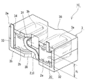
[実施形態1]
図1から図4を参照して、実施形態1のリアクトル1A,実施形態の磁性コア3を説明する。図2は、図1に示すコイル2Aを巻回部2a,2bの軸方向に直交する平面で切断した状態を示す。図3は、図1に示すリアクトル1Aについてコイル2Aの接続部2jAが配置された側を、巻回部2a,2bの並び方向(図3では左右方向)に直交する方向からみた正面図である。
[Embodiment 1]
The
(リアクトル)
<概要>
実施形態1のリアクトル1Aは、図1に示すように巻線2wが巻回されてなる二つの巻回部2a,2bを含むコイル2Aと、各巻回部2a,2bが配置される磁性コア3とを備える。実施形態の磁性コア3は特定の形状であり、端的にいうと、上述したEEコアに対して、中脚の両側に、この中脚を挟むように二つの磁脚を備える。磁性コア3は、互いに離間して並列に配置される五つの磁脚(内側脚部3a,3b、中央脚部31、外側脚部32,33、図2も参照)と、これらを挟み、これらを連結する二つの連結部34,35とを備える。この例の磁性コア3は、複数の分割コア片3α,3βの組物である(図4)。この例のリアクトル1Aは、コンバータケースなどの設置対象(図示せず)の載置面に対して、巻回部2a,2bの軸方向(又は内側脚部3a,3bの軸方向)が直交するように設置される縦置き形態で使用される。また、この例のリアクトル1Aは、コイル2Aとして、両巻回部2a,2bが、各巻回部2a,2bを貫通する磁束の向きが同じになるように接続される上述の順磁束コイルを備える。以下、構成要素ごとに詳細に説明する。
(Reactor)
<Overview>
The
(コイル)
<概要>
コイル2Aは、図4に示すように1本の巻線2wが螺旋状に巻回されてなる筒状の巻回部2a,2bと、巻線2wにおける両巻回部2a,2b間に配置される部分から構成され、両巻回部2a,2bを電気的に接続する接続部2jAとを備える。両巻回部2a,2bは、各軸が平行するように所定の間隔(ここでは、中央脚部31の幅W31(図2)以上)をあけて横並びされる。
(coil)
<Overview>
As shown in FIG. 4, the
<巻線>
この例の巻線2wは、銅などからなる導体線と、導体線の外周を覆うポリアミドイミドなどの絶縁材料からなる絶縁被覆とを備える被覆線であり、横断面形状が長方形状である平角線である。この例の巻回部2a,2bは、エッジワイズコイルである。巻線2wを丸線などの種々の形状の線材とすることができる。本例のように平角線のエッジワイズコイルとすると、丸線コイルに比較して、占積率を高めて小型化し易い(特に軸長さを短くし易い)上に、縦置き形態では、(1)巻線2wの厚さを薄くすることで、コイル2の設置高さを低くし易い、(2)コイル2Aの端面(図4では上面及び下面)を概ね平坦な面状にし易い、といった利点を有する。
<Winding>
The winding 2w of this example is a covered wire including a conductor wire made of copper or the like and an insulating coating made of an insulating material such as polyamide imide that covers the outer periphery of the conductor wire, and is a rectangular wire having a rectangular cross-sectional shape. It is. The winding
<巻回部>
この例の巻回部2a,2bは、同一形状であり、端面形状が角部を丸めた長方形状である四角筒状である。巻回部2a,2bの形状は適宜選択でき、例えば円筒状などとすることができる。また、この例の巻回部2a,2bは、巻回方向及びターン数が同じであり、コイル2Aに通電された際に各巻回部2a,2bを貫通する磁束の向きが同じになるように接続部2jAによって接続される。このようなコイル2Aは、総ターン数が同じである一つの巻回部を二分して二つの巻回部2a,2bとして備えるものといえ、総ターン数が同じである一つの巻回部を有するコイル(以下、単一コイルと呼ぶ)よりも軸長さが短い。従って、リアクトル1Aを縦置きに設置すれば、その設置高さは、単一コイルを備える場合に比較して低い。なお、各巻回部2a,2bの巻回方向、ターン数は適宜選択できる。この例のように巻回方向が同じであると、巻回部2a,2bを形成し易く、コイル2Aの製造性に優れる。この例のようにターン数が同じであると、コイル2Aの軸長さを最も短くできるため、縦置き形態のリアクトル1Aの設置高さを低くできる。
<Winding part>
The winding
<接続部>
この例の接続部2jAは、両巻回部2a,2bをつくる1本の連続する巻線2wにおいて、巻回部2a,2b間に配置される部分が適宜曲げられて構成される。ここでの接続部2jAは、一方の巻回部2aにおける下側の端面と、他方の巻回部2bにおける上側の端面とを繋ぐように逆J字状に折り曲げられた部分(二か所のフラットワイズ曲げ部分及び二か所のエッジワイズ曲げ部分)を有する。また、ここでの接続部2jAは、その一部が、図3に示すようにリアクトル1Aを縦置きに設置した場合に磁性コア3の設置面(ここでは下方の連結部35の下面)と対向する面(ここでは上方の連結部34の上面)から突出する大きさとする。接続部2jAの形状、大きさは適宜選択できる(後述する実施形態2,3も参照)。接続部2jAの高さ方向に沿った大きさは、例えば、巻回部2a,2bの軸長さに応じて調整するとよく、幅方向に沿った大きさは、例えば、中央脚部31の幅W31に応じて調整するとよい。この例のように接続部2jAの一部を磁性コア3から突出させると、コイル2Aを形成し易く製造性に優れる。コイル2Aと磁性コア3との組み付け後に、この突出部分を連結部34の上面に重なるように折り曲げると、縦置き形態のリアクトル1Aの設置高さをより低くできる。
<Connection>
The connection portion 2jA of this example is configured by appropriately bending a portion disposed between the winding
<端部>
各巻回部2a,2bに連続する巻線2wの各端部は、電源などの外部装置との接続箇所に利用される。ここでは、巻線2wの各端部は、巻回部2a,2bから離れるように上方に引き出されて、接続部2jAに横並びされる場合を例示するが、引出方向、引出長さなどは適宜変更できる。
<End>
Each end of the winding 2w continuous with each of the winding
<その他の構成>
コイル2Aは、巻回部2a,2bの外周の少なくとも一部を覆う樹脂モールド部(図示せず)を備えることができる。樹脂モールド部は、例えば、巻回部2a,2bの内外の実質的に全体を覆う形態、巻回部2a,2bの内周面及び外周面並びに端面の少なくとも一部を覆わずに露出させた形態などとすることができる。巻回部2a,2bにおいて、磁性コア3に覆われない露出箇所(後述)を樹脂モールド部からも露出させると、放熱性を高め易い。樹脂モールド部が、巻回部2a,2bと磁性コア3間に介在されることで、コイル2Aと磁性コア3間の電気絶縁性を高められる。なお、樹脂モールド部を備えていない場合でも、巻線2wとして上述の被覆線を利用すれば、コイル2Aと磁性コア3間の電気絶縁性を高められる。
<Other configurations>
The
樹脂モールド部の構成材料は、例えば、熱可塑性樹脂、熱硬化性樹脂などの絶縁性樹脂が挙げられる。熱可塑性樹脂は、例えば、ポリフェニレンスルフィド(PPS)樹脂、ポリテトラフルオロエチレン(PTFE)樹脂、液晶ポリマー(LCP)、ナイロン6やナイロン66といったポリアミド(PA)樹脂、ポリブチレンテレフタレート(PBT)樹脂、アクリロニトリル・ブタジエン・スチレン(ABS)樹脂などが挙げられる。熱硬化性樹脂は、例えば、不飽和ポリエステル樹脂、エポキシ樹脂、ウレタン樹脂、シリコーン樹脂などが挙げられる。絶縁性樹脂にアルミナやシリカなどの非磁性かつ非金属粉末を含有することができる。この場合、放熱性や電気絶縁性などを向上できる。 The constituent material of the resin mold portion includes, for example, an insulating resin such as a thermoplastic resin and a thermosetting resin. Examples of the thermoplastic resin include polyphenylene sulfide (PPS) resin, polytetrafluoroethylene (PTFE) resin, liquid crystal polymer (LCP), polyamide (PA) resin such as nylon 6 and nylon 66, polybutylene terephthalate (PBT) resin, and acrylonitrile. -Butadiene-styrene (ABS) resin and the like. Examples of the thermosetting resin include an unsaturated polyester resin, an epoxy resin, a urethane resin, and a silicone resin. Non-magnetic and non-metallic powders such as alumina and silica can be contained in the insulating resin. In this case, heat dissipation and electrical insulation can be improved.
(磁性コア)
<概要>
実施形態の磁性コア3は、巻線2wが巻回されてなる二つの巻回部2a,2bを含むコイル2Aが組み付けられるリアクトル1Aに用いられる。この磁性コア3は、各巻回部2a,2bの内周に配置される内側脚部3a,3bと、両巻回部2a,2b間に介在される中央脚部31と、両内側脚部3a,3b及び中央脚部31を挟む二つの外側脚部32,33と、並列される両内側脚部3a,3b、中央脚部31、両外側脚部32,33を挟み、これらを連結する二つの連結部34,35とを備える。中央脚部31は、各内側脚部3a,3bと離間して配置される。各外側脚部32,33は、各内側脚部3a,3bと離間して配置される(図2,図4)。この配置によってできる各部間の隙間を巻回部2a,2bの配置箇所とする。詳しくは、図2に示すように、中央脚部31と一方の内側脚部3a間の幅Wcの隙間及び一方の内側脚部3aと一方の外側脚部32間の幅Wsの隙間を一方の巻回部2aの配置箇所とする。中央脚部31と他方の内側脚部3b間の幅Wcの隙間及び他方の内側脚部3bと他方の外側脚部33間の幅Wsの隙間を他方の巻回部2bの配置箇所とする。両外側脚部32,33は、両巻回部2a,2bの外周から、内側脚部3a、中央脚部31、内側脚部3bという順に並べられた脚部群を挟むように設けられる。
(Magnetic core)
<Overview>
The
<構成材料>
磁性コア3は、磁性粉末と樹脂とを含む複合材料の成形体を備えることができる。磁性粉末の粒子は、軟磁性金属や軟磁性非金属から構成される粒子、軟磁性金属粒子の外周にリン酸塩などで構成される絶縁被覆を備える被覆粒子などが挙げられる。軟磁性金属は純鉄などの鉄族金属や鉄基合金(Fe−Si合金、Fe−Ni合金など)など、軟磁性非金属はフェライトなどが挙げられる。
<Constituent materials>
The
複合材料中の磁性粉末の含有量は、30体積%以上80体積%以下、樹脂の含有量は10体積%以上70体積%以下が挙げられる。飽和磁束密度や放熱性の向上の観点から、磁性粉末の含有量を50体積%以上、更に55体積%以上、60体積%以上とすることができる。製造過程での流動性の向上の観点から、磁性粉末の含有量を75体積%以下、更に70体積%以下とすることができる。 The content of the magnetic powder in the composite material is 30% by volume or more and 80% by volume or less, and the content of the resin is 10% by volume or more and 70% by volume or less. From the viewpoint of improving the saturation magnetic flux density and heat dissipation, the content of the magnetic powder can be set to 50% by volume or more, further 55% by volume or more, and 60% by volume or more. From the viewpoint of improving the fluidity during the manufacturing process, the content of the magnetic powder can be set to 75% by volume or less, and further 70% by volume or less.
複合材料中の樹脂は、上述の樹脂モールド部の項で説明した熱硬化性樹脂、熱可塑性樹脂、その他、常温硬化性樹脂、低温硬化性樹脂などが挙げられる。不飽和ポリエステルに炭酸カルシウムやガラス繊維が混合されたBMC(Bulk molding compound)、ミラブル型シリコーンゴム、ミラブル型ウレタンゴムなども利用できる。 Examples of the resin in the composite material include a thermosetting resin, a thermoplastic resin, and a room-temperature-curable resin and a low-temperature-curable resin described above in the section of the resin mold section. BMC (Bulk molding compound) in which calcium carbonate and glass fiber are mixed with unsaturated polyester, millable silicone rubber, millable urethane rubber, and the like can also be used.
磁性粉末及び樹脂に加えて、アルミナやシリカなどの非磁性かつ非金属粉末を含有する複合材料とすることができる。非磁性かつ非金属粉末の含有量は、0.2質量%以上20質量%以下、更に0.3質量%以上15質量%以下、0.5質量%以上10質量%以下が挙げられる。 A composite material containing a nonmagnetic and nonmetallic powder such as alumina or silica in addition to the magnetic powder and the resin can be obtained. The content of the nonmagnetic and nonmetallic powder is 0.2% by mass to 20% by mass, further 0.3% by mass to 15% by mass, and 0.5% by mass to 10% by mass.
複合材料の成形体は、射出成形や注型成形などの適宜な成形方法によって製造できる。例えば、適宜な形状の成形型にコイル2Aを収納して、コイル2Aの内外に流動状態の複合材料を充填すれば、一体成形された磁性コア3を製造できる。適宜な形状の成形型を利用すれば、複合材料の成形体から構成される分割コア片を製造できる。複合材料の成形体は、複雑な形状であっても容易に成形でき、製造性に優れる。
The molded body of the composite material can be produced by an appropriate molding method such as injection molding or cast molding. For example, if the
又は、磁性コア3は、磁性粉末を含む圧粉成形体を備えることができる。圧粉成形体は、代表的には、磁性粉末とバインダーとを含む混合粉末を所定の形状に圧縮成形したもの、更に成形後に熱処理を施したものが挙げられる。バインダーは樹脂などを利用でき、その含有量は30体積%以下程度が挙げられる。熱処理を施すと、バインダーが消失したり、熱変性物になったりする。適宜な形状の成形型を利用することで、圧粉成形体から構成される分割コア片を製造できる。圧粉成形体は、複合材料の成形体よりも磁性粉末の含有量を高められて、飽和磁束密度が高い磁性コアなどを構築し易い。
Alternatively, the
又は、磁性コア3は、珪素鋼板などの軟磁性板を積層した積層体、フェライトコアなどの焼結体などを備えることができる。
Alternatively, the
磁性コア3は、ギャップ材やエアギャップを備えることができる。ギャップ材は、アルミナなどの非磁性材料から構成されるもの、磁性材料と非磁性材料との混合物から構成され、比透磁率が分割コア片などの成形体よりも低いものなどが挙げられる。磁性コア3が複合材料の成形体などを含み、磁気飽和し難い場合にはギャップ材やエアギャップといった磁気ギャップを省略したり、磁気ギャップを少なくしたりできる。この場合、磁気ギャップ部分での漏れ磁束に起因する損失を低減し易く、コイル2Aと磁性コア3とを近接配置でき、より小型にし易い。
The
<成形状態>
磁性コア3は、一体成形物とすることができる。この場合、上述のように複合材料の成形体とすると容易に製造できる。また、この場合、樹脂モールド部を備えるコイル2Aなどとすると、コイル2Aの形状を維持し易い。図2は、一体成形物である磁性コア3を中央脚部31などの脚部群の軸方向に直交する平面で切断した横断面に類似する。
<Molded state>
The
又は、磁性コア3は、この例のように複数の分割コア片の組物とすると、コイル2Aと組み付け易く、リアクトル1Aの製造性に優れる。分割数や各分割コア片の形状、構成材料などは適宜選択できる。この例の磁性コア3は、図4に示すように、一対の分割コア片3α,3βを組み合わせて構成される。一方の分割コア片3αは、一方の連結部34と、連結部34から立設され、各内側脚部3a,3bの一部を形成する二つの内脚片3αa,3αb、及び中央脚部31の一部を形成する中央脚片31α、並びに各外側脚部32,33の一部を形成する二つの外脚片32α,33αとを備える。他方の分割コア片3βは、他方の連結部35と、連結部35から立設され、各内側脚部3a,3bの他部を形成する二つの内脚片3βa,3βb、及び中央脚部31の他部を形成する中央脚片31β、並びに各外側脚部32,33の他部を形成する二つの外脚片32β,33βとを備える。この例では、各分割コア片3α,3βの端面形状(横断面形状も同様)が図2に示すように幅方向の中心線Lwを中心として対称形状であり、かつ長さ方向の中心線Llを中心として対称形状である。このように分割コア片3α,3βを同一形状、同一の大きさ、かつ対称形状とすると、分割コア片の製造性に優れる。また、この例のように一対の分割コア片3α,3βの組物とすると、組み付け工程が少なく、リアクトル1Aの組立作業性に優れる。磁性コア3は、異なる材料から構成される分割コア片を含む形態(例えば、複合材料の成形体から構成される分割コア片と圧粉成形体から構成される分割コア片とを含む形態など)、全ての分割コア片が同じ材料から構成される形態のいずれも利用できる。
Alternatively, if the
<中央脚部、内側脚部、外側脚部、連結部>
この例の内側脚部3a,3bは、図1,図2,図4に示すように、同一形状、同一の大きさである。また、この例の内側脚部3a,3bは、その軸方向(代表的には巻回部2a,2bの軸方向に実質的に同軸)に直交する平面で切断した横断面形状(ここでは、内脚片3αa,3αb,3βa,3βbの端面形状に等しい)が巻回部2a,2bの内周形状に対応した形状である直方体状である。内側脚部3a,3bの形状、大きさは、その横断面積が所定の磁路面積を有すれば、巻回部2a,2bの形状、大きさに応じて適宜選択できる。この例のように内側脚部3a,3bの外周形状と、巻回部2a,2bの内周形状とが相似状であると、磁性コア3とコイル2Aとを近付けて組み付け易く、小型にできる。
<Central leg, inner leg, outer leg, connecting part>
The
この例の中央脚部31は、図2から図4に示すように直方体状であり、その軸方向(代表的には巻回部2a,2bの軸方向に実質的に平行)に直交する平面で切断した横断面形状(ここでは、中央脚片31α、31βの端面形状に等しい)が長方形状である。中央脚部31は、所定の磁路断面積を有するように、その大きさ(横断面積など)を調整している。中央脚部31の磁路断面積は、例えば、一つの内側脚部(3a又は3b)の横断面積の50%以上、更に60%以上、70%以上であると、磁路として機能できると期待される。この例では、中央脚部31の横断面積は、一つの内側脚部(3a又は3b)の横断面積に実質的に等しい。中央脚部31の幅W31及び長さL31はそれぞれ、内側脚部3a,3bの幅及び長さL3a,L3bに実質的に等しい。
The
この例の外側脚部32,33は、図2から図4に示すように同一形状、同一の大きさである。また、この例の外側脚部32,33は、その軸方向(代表的には巻回部2a,2bの軸方向に実質的に平行)に直交する平面で切断した横断面形状(ここでは、外脚片32α,32β,33α,33βの端面形状に等しい)が長方形である。外側脚部32,33の形状、大きさは、各横断面積が所定の磁路面積を有すれば、巻回部2a,2bの形状、大きさなどに応じて適宜選択できる。この例では、各外側脚部32,33の横断面積は、一つの内側脚部(3a又は3b)の横断面積の実質的に半分に等しい。また、この例では、各外側脚部32,33の幅は一つの内側脚部の幅よりも小さく、外側脚部32,33の長さL32,L33は、内側脚部3a,3bの長さL3a,L3bよりも長い。そのため、両外側脚部32,33における長さ方向の両側は、内側脚部3a,3b及び中央脚部31の脚部群よりも突出している。
The
この例の連結部34,35は、同一形状、同一の大きさの薄い直方体状であり、一面を設置対象の載置面に配置される設置面(図1,図3では連結部35の下面)とする。また、連結部34,35は、互いに離間して横並びされる脚部群、即ち外側脚部32、内側脚部3a、中央脚部31、内側脚部3b、外側脚部33を挟むことが可能な幅W34,W35及び長さL34,L35を有する。この例では、図2,図4に示すように連結部34,35の幅方向及び長さ方向の中央部に中央脚部31が設けられ、中央脚部31の両側に、内側脚部3a及び外側脚部32の組、内側脚部3b及び外側脚部33の組が設けられている。また、この例では、幅方向の中央部に台形状に切り欠いた切欠部38が設けられており、長さが部分的に異なる箇所を有する。連結部34,35の幅方向の両縁が各外側脚部32,33の幅方向の両側に位置する側面の縁に一致し、連結部34,35における幅方向の両側の長さL34,L35は、外側脚部32,33の長さL32,L33に等しい。一方、連結部34,35における幅方向の中央部、即ち中央脚部31が設けられた領域の長さは、上述の切欠部38が設けられることで、内側脚部3a,3bの長さL3a,L3bに等しい。連結部34,35において、各内側脚部3a,3bの長さ方向の両側に設けられる領域はそれぞれ、巻回部2a,2bの配置箇所に利用する(図2)。この領域の合計長さは、上述の長さL34,L35と長さL3a,L3bとの差に相当する。
The connecting
この例の磁性コア3は、各内側脚部3a,3bと中央脚部31間、隣り合う内側脚部と外側脚部間(3a,32),(3b,33)にそれぞれ、図2に示すように、直線的な隙間が設けられる。これらの隙間の幅Wc,Wsがいずれも、巻回部2a,2bの幅よりも若干大きくなるように、連結部34,35の幅W34,W35を調整している。こうすることで、コイル2Aと磁性コア3間の絶縁性を高められると共に、コイル2Aと分割コア片3α,3βとを組み付け易い。
The
また、この例の磁性コア3は、コイル2Aが組み付けられた場合に巻回部2a,2bにおける外周面のうち、長さ方向の両側に配置される面(図2では上下の面)が磁性コア3Aに覆われず露出され(図1,図3)、その他の領域が磁性コア3に概ね覆われるように連結部34,35の長さL34,L35を調整している。ここでは、巻回部2a,2bにおける磁性コア3からの露出箇所が、連結部34,35における長さ方向の両側に配置される端面(図2では上下面)と実質的に面一になるように、長さL34,L35,及び長さL3a,L3b,L31を調整している。巻回部2a,2bの露出箇所は、例えば、リアクトル1Aの使用時に放熱面として利用できる。
In the
(用途)
実施形態1のリアクトル1Aは、ハイブリッド自動車、プラグインハイブリッド自動車、電気自動車、燃料電池自動車などの車両に搭載される車載用コンバータ(代表的にはDC−DCコンバータ)や空調機のコンバータなどの種々のコンバータ、電力変換装置の構成部品に利用できる。特に、実施形態1のリアクトル1Aは、大きなインダクタンスが求められ、ターン数が比較的多い上に低背化が望まれる場合に好適に利用できる。実施形態の磁性コア3は、リアクトル1Aなどの構成要素に利用できる。
(Application)
The
(主要な効果)
実施形態1のリアクトル1Aは、コイル2Aの総ターン数が比較的多くても、巻回部2a,2bに分けた順磁束コイルとするため、コイル2Aの軸長さを総ターン数が同じ単一コイルよりも短くできる。このような順磁束コイルと特定の形状の磁性コア3とを備えるリアクトル1Aを縦置きに配置すれば、設置高さを低くできる。この点から、実施形態1のリアクトル1Aは、小型である。コイル2Aの接続部2jAを上述のように折り曲げるなどして、コイル2Aにおける磁性コア3からの突出量をより小さくすれば、リアクトル1Aの設置高さを更に小さくできる。実施形態のリアクトル用磁性コア3は、例えば、上記順磁束コイルを備え、縦置き形態とするリアクトル1Aに利用すると、低背化に寄与する。
(Major effects)
Since the
また、実施形態1のリアクトル1Aは、内側脚部3a,3b及び外側脚部32,33に加えて、中央脚部31を有する磁性コア3を備えるため、各巻回部2a,2bからの磁束が磁性コア3外に漏れ難い。従って、実施形態1のリアクトル1Aは、低損失である。実施形態のリアクトル用磁性コア3は、例えば、上記順磁束コイルを備えるリアクトル1Aに利用すると、漏れ磁束を低減でき、損失の低減に寄与する。
Further, the
その他、この例のリアクトル1Aは、以下の効果を奏する。
(1)巻回部2a,2bの外周面と磁性コア3の外表面とが面一である部分を有して、コイル2Aにおいて磁性コア3から突出する箇所が少ない。ここでは、上記突出箇所が、実質的に巻線2wの両端部及び接続部2jAの一部のみであり、リアクトル1Aの設置面積は、磁性コア3の設置面(連結部35の下面)の面積に実質的に等しい。設置面積が小さい点からも小型である。
(2)巻回部2a,2bにおいて磁性コア3に覆われない露出箇所を含むため、放熱性を高められる。
(3)磁性コア3が巻回部2a,2bの配置箇所を有するため、コイル2Aと磁性コア3とを容易に位置決めできる上に、磁性コア3が一組の分割コア片3α,3βの組物であるため、コイル2Aと磁性コア3とを容易に組み付けられる。そのため、リアクトル1Aの製造性に優れる。
(4)磁性コア3が同一形状の分割コア片3α,3βの組物である上に、各分割コア片3α,3βは対称形状であり、単純な形状であるため、磁性コア3の製造性に優れる。
(5)磁性コア3が切欠部38を備えることで、磁性コア3の軽量化、ひいてはリアクトル1Aの軽量化を図ることができる。なお、切欠部38の形成箇所は、巻回部2a,2bからの磁束がそれほど通過しない箇所であるため、除去しても、所定の磁路面積を確保できる。
In addition, the
(1) The outer peripheral surfaces of the winding
(2) Since the winding
(3) Since the
(4) Since the
(5) Since the
以下、図5,図6を参照して、コイル2Aの接続部2jAの別例を説明する。
図5に示す実施形態2のリアクトル1B、図6に示す実施形態3のリアクトル1Cの基本的構成は、上述の実施形態1のリアクトル1Aと同様である。各リアクトル1B,1Cに備えるコイル2B,2Cの接続部2jB,2jCの構造が接続部2jAとは異なる。
以下、接続部2jB,2jCを詳細に説明し、その他の構成及び効果は詳細な説明を省略する。
Hereinafter, another example of the connection portion 2jA of the
The basic configuration of
Hereinafter, the connection portions 2jB and 2jC will be described in detail, and other configurations and effects will not be described in detail.
[実施形態2]
実施形態2のリアクトル1Bに備えるコイル2Bは、2本の巻線2wa,2wbで構成されている点で、上述のコイル2Aとは異なる。コイル2Bに備える各巻回部2a,2bは、異なる巻線2wa,2wbから構成される。コイル2Bは、両巻線2wa,2wbの端部を電気的に接続する接続部2jBを備える。
[Embodiment 2]
The
各巻回部2a,2bを構成する巻線2wa,2wbの一端部をそれぞれ、外部装置との接続箇所とし、他端部を接続部2jBの形成箇所とする。この例では、一方の巻線2waの他端部は、上方に向かって延設される部分と、他方の巻回部2bに向かって延設される部分と、両部分を形成するために折り返した部分とを有し、逆L字状に形成されている。他方の巻線2wbの他端部は、一端部と同様に上方に向かって延設される部分を有する。接続部2jBは、巻線2wa,2wbの他端部の先端同士を接合する部分を含む。この接合には、溶接(TIG溶接、レーザ溶接、抵抗溶接など)、圧着、冷間圧接、振動溶着などの直接接合、半田、ロウ材などを用いた間接接合のいずれも利用できる。また、この接合は、コイル2Bと磁性コア3との組付前後のいずれにも行える。例えば、コイル2Bと一方の分割コア片との組み付け後などに上述の接合を行える。
One end of each of the windings 2wa and 2wb constituting each of the winding
実施形態2のリアクトル1Bは、実施形態1のリアクトル1Aと同様に、コイル2Bを順磁束コイルとし、かつ特定の形状の磁性コア3を備えるため、縦置きした場合に設置高さを低くできる。また、このリアクトル1Bは、磁性コア3によって漏れ磁束を低減でき、低損失である。特に、実施形態2のリアクトル1Bは、巻回部2a,2bをそれぞれ異なる巻線2wa,2wbで構成するため、各巻回部2a,2bを形成し易く、コイル2Bの製造性にも優れる。隣り合う巻回部が存在しない状態で、巻線2wa,2wbの他端部の折り曲げや折り返しを行えて、接続部2jBを形成し易いことからも、コイル2Bの製造性に優れる。その他、接続部2jBを構成する巻線2wa,2wbの他端部の長さを調整することで、巻回部2a,2b間の間隔を高精度に調整できる上に、組み付ける磁性コア3の寸法(製造誤差を含む)に対応した調整も可能であり、寸法精度に優れるリアクトル1Bとすることができる。
Like the
[実施形態3]
実施形態3のリアクトル1Cに備えるコイル2Cは、接続部2jCが磁性コア3から突出していない点で、上述のコイル2Aとは異なる。この例の接続部2jCは、一方の巻回部2aにおける下側の端面から他方の巻回部2bにおける上側の端面に渡るようにS字状に折り曲げられた部分を有する。接続部2jCの高さは、巻回部2a,2bの高さH2に実質的に等しい。
[Embodiment 3]
The coil 2C provided in the
実施形態3のリアクトル1Cは、実施形態1のリアクトル1Aと同様に、コイル2Cを順磁束コイルとし、かつ特定の形状の磁性コア3を備えるため、縦置きした場合に設置高さを低くできる。また、このリアクトル1Cは、磁性コア3によって漏れ磁束を低減でき、低損失である。特に、実施形態3のリアクトル1Cでは、その高さ方向において、接続部2jCが巻回部2a,2b及び磁性コア3の双方から実質的に突出しないため、設置高さがより低い。このように接続部2jCの形成位置、形状などを調整することで、設置高さがより低いリアクトル1Cを構築できる。上述の実施形態2で説明した巻線2wa,2wbの他端部において、折り曲げ位置や延長部分の長さなどを調整すれば、リアクトル1Bの高さ方向において、磁性コア3から突出しない接続部2jBとすることができる。
Similar to the
[実施形態4]
実施形態1から3では、コイル2Aから2Cがいずれも順磁束コイルである場合を説明した。順磁束コイルに代えて、コイル2Aなどに通電した際に各巻回部2a,2bを貫通する磁束の向きが逆になる逆磁束コイルにすることができる。実施形態1,3のように1本の巻線2wで逆磁束コイルを構成する場合、各巻回部2a,2bを貫通する磁束の向きが逆になるように、巻線2wにおける両巻回部2a,2bを接続する部分を折り返すことが挙げられる(特許文献1の図1など参照)。実施形態2のように2本の巻線2wa,2wbによって逆磁束コイルを構成する場合、各巻回部2a,2bの巻き方向を同じとし、各巻回部2a,2bを貫通する磁束の向きが逆になるように、一方の巻線の他端部を折り返して、両他端部同士を接合するとよい。その他、公知である種々の形状の逆磁束コイルを適用できる。
[Embodiment 4]
In the first to third embodiments, the case where all of the
逆磁束コイルを備える実施形態4のリアクトルは、特に、内側脚部3a,3b及び外側脚部32,33に加えて、中央脚部31を有する磁性コア3を備えるため、各巻回部2a,2bからの磁束を中央脚部31に流すことができる。そのため、使用電流値が大きくなっても、磁束飽和が生じ難く、インダクタンスが低下し難い。
The reactor according to the fourth embodiment including the reverse magnetic flux coil particularly includes the
[変形例]
上述の実施形態1から4に対して、以下の少なくとも一つの変更や追加が可能である。
(1)温度センサ、電流センサ、電圧センサ、磁束センサなどのリアクトルの物理量を測定するセンサ(図示せず)を備える。
(2)巻回部2a,2bの露出箇所に放熱板を備える。
(3)樹脂モールド部に代えて、ボビンなどの絶縁介在部材を備える。
(4)樹脂モールド部に代えて、又は樹脂モールド部の具備に加えて、巻回部2a,2bを構成する隣り合うターン同士を接合する熱融着樹脂部(図示せず)を備える。
(5)コイル2Aなどと磁性コア3とを含む組物を収納するケース(例、アルミニウムやアルミニウム合金などの金属)を備える。更に、組物とケースの内底面間に放熱層を備える。放熱層の具体的な材料は、放熱性に優れるフィラー(アルミナなどの非磁性かつ非金属粉末)と樹脂(接着剤でもよい)とを含むものが挙げられる。
[Modification]
At least one of the following changes and additions to
(1) A sensor (not shown) for measuring a physical quantity of the reactor, such as a temperature sensor, a current sensor, a voltage sensor, and a magnetic flux sensor, is provided.
(2) A heat radiating plate is provided at the exposed portions of the winding
(3) An insulating interposed member such as a bobbin is provided instead of the resin mold portion.
(4) A heat-sealing resin portion (not shown) for joining adjacent turns forming the winding
(5) A case (for example, a metal such as aluminum or an aluminum alloy) for storing an assembly including the
本発明は、これらの例示に限定されるものではなく、特許請求の範囲によって示され、特許請求の範囲と均等の意味及び範囲内での全ての変更が含まれることが意図される。
例えば、横置き形態とすることができる。この場合、巻回部2a,2bの露出箇所を設置面とする形態、一方の外側脚部を設置面とする形態などとすることができる。
The present invention is not limited to these examples, but is indicated by the appended claims, and is intended to include all modifications within the scope and meaning equivalent to the appended claims.
For example, it can be in a horizontal configuration. In this case, the exposed portions of the winding
1A,1B,1C リアクトル
2A,2B,2C コイル
2a,2b 巻回部
2jA,2jB,2jC 接続部
2w,2wa,2wb 巻線
3 磁性コア
3α,3β 分割コア片
3a,3b 内側脚部
31 中央脚部
32,33 外側脚部
34,35 連結部
3αa,3βa,3αb,3βb 内脚片
31α,31β 中央脚片
32α,32β,33α,33β 外脚片
38 切欠部
1A, 1B,
Claims (6)
各巻回部が配置される磁性コアとを備え、
前記巻線は、
導体線と、前記導体線の外周を覆う絶縁被覆とを備える被覆線であり、
前記磁性コアは、
前記各巻回部の内周に配置される内側脚部と、
前記両巻回部間に介在される中央脚部と、
前記両巻回部の外周から両内側脚部及び前記中央脚部を挟む二つの外側脚部と、
並列される前記両内側脚部、前記中央脚部、両外側脚部を挟み、これらを連結する二つの連結部とを備え、
前記内側脚部、前記中央脚部、及び前記外側脚部の並び方向、及びこれら脚部の軸方向の双方に直交する方向を長さ方向とし、
前記中央脚部の長さと前記内側脚部の長さとが実質的に等しく、
前記外側脚部の長さが前記中央脚部の長さ及び前記内側脚部の長さよりも長く、
前記連結部は、前記連結部における前記中央脚部の形成領域の長さが前記内側脚部の長さに等しくなるように切り欠かれた切欠部を備えるリアクトル。 A coil including two winding portions formed by winding windings and a connection portion connecting the two winding portions ,
A magnetic core on which each winding part is arranged,
The winding is
A conductor wire, and a covered wire including an insulating coating covering an outer periphery of the conductor wire,
The magnetic core,
Inner leg portions arranged on the inner periphery of each of the winding portions,
A central leg portion which is interposed between the two winding portion,
Two outer legs sandwiching both inner legs and the central leg from the outer periphery of the two winding portions,
The two inner legs, the center leg, and the two outer legs that are arranged side by side, and two connecting portions that connect these .
The direction in which the inner leg, the central leg, and the outer leg are arranged, and a direction perpendicular to both the axial directions of these legs is a length direction,
Wherein the length of the central leg and the length of the inner leg are substantially equal,
The length of the outer leg is longer than the length of the central leg and the length of the inner leg,
The connecting portion, a reactor length of the formation region of the central leg portion of the connecting portion is Ru with a notch is cut out to be equal to the length of the inner leg.
前記接続部は、両巻線の端部を直接接合又は間接接合する部分を含む請求項1又は請求項2に記載のリアクトル。 Wherein each turn is comprised of a different said winding,
3. The reactor according to claim 1 , wherein the connection portion includes a portion that directly or indirectly joins ends of both windings. 4.
各分割コア片は、一方の前記連結部と、前記連結部から立設され、各内側脚部の一部を形成する二つの内脚片及び前記中央脚部の一部を形成する中央脚片並びに各外側脚部の一部を形成する二つの外脚片とを備える請求項1から請求項4のいずれか1項に記載のリアクトル。 The magnetic core is configured by combining a pair of split core pieces,
Each split core piece is one of the connecting parts, and two inner leg pieces that are erected from the connecting part and form a part of each inner leg part and a central leg piece that forms a part of the central leg part. The reactor according to any one of claims 1 to 4, further comprising: two outer leg pieces forming a part of each outer leg portion.
各巻回部の内周に配置される内側脚部と、
各内側脚部と離間して配置されると共に、両内側脚部間に介在される中央脚部と、
各内側脚部と離間して配置されると共に、前記両内側脚部及び前記中央脚部を挟む二つの外側脚部と、
並列される前記両内側脚部、前記中央脚部、両外側脚部を挟み、これらを連結する二つの連結部とを備え、
前記内側脚部、前記中央脚部、及び前記外側脚部の並び方向、及びこれら脚部の軸方向の双方に直交する方向を長さ方向とし、
前記中央脚部の長さと前記内側脚部の長さとが実質的に等しく、
前記外側脚部の長さが前記中央脚部の長さ及び前記内側脚部の長さよりも長く、
前記連結部は、前記連結部における前記中央脚部の形成領域の長さが前記内側脚部の長さに等しくなるように切り欠かれた切欠部を備えるリアクトル用磁性コア。
A magnetic core for a reactor to which a coil including two winding portions formed by winding windings and a connection portion connecting the two winding portions is assembled,
Inner legs arranged on the inner periphery of each winding part,
A central leg interposed between both inner legs, while being spaced apart from each inner leg,
Two outer legs sandwiching the inner legs and the central leg are arranged separately from each inner leg,
The two inner legs, the center leg, and the two outer legs that are arranged side by side, and two connecting portions that connect these .
The direction in which the inner leg, the central leg, and the outer leg are arranged, and a direction perpendicular to both the axial directions of these legs is a length direction,
Wherein the length of the central leg and the length of the inner leg are substantially equal,
The length of the outer leg is longer than the length of the central leg and the length of the inner leg,
The connecting portion, the central leg cut-out notch reactor magnetic core Ru provided with such a length equal to the length of the inner leg of the formation region of the said connecting portion.
Priority Applications (4)
| Application Number | Priority Date | Filing Date | Title |
|---|---|---|---|
| JP2016184616A JP6635306B2 (en) | 2016-09-21 | 2016-09-21 | Magnetic core for reactors and reactors |
| PCT/JP2017/031942 WO2018056049A1 (en) | 2016-09-21 | 2017-09-05 | Reactor, and magnetic core for reactor |
| US16/335,100 US11417455B2 (en) | 2016-09-21 | 2017-09-05 | Reactor and magnetic core for reactor |
| CN201780057647.XA CN109716459B (en) | 2016-09-21 | 2017-09-05 | Reactor and magnetic core for reactor |
Applications Claiming Priority (1)
| Application Number | Priority Date | Filing Date | Title |
|---|---|---|---|
| JP2016184616A JP6635306B2 (en) | 2016-09-21 | 2016-09-21 | Magnetic core for reactors and reactors |
Publications (3)
| Publication Number | Publication Date |
|---|---|
| JP2018049948A JP2018049948A (en) | 2018-03-29 |
| JP2018049948A5 JP2018049948A5 (en) | 2019-03-07 |
| JP6635306B2 true JP6635306B2 (en) | 2020-01-22 |
Family
ID=61690912
Family Applications (1)
| Application Number | Title | Priority Date | Filing Date |
|---|---|---|---|
| JP2016184616A Active JP6635306B2 (en) | 2016-09-21 | 2016-09-21 | Magnetic core for reactors and reactors |
Country Status (4)
| Country | Link |
|---|---|
| US (1) | US11417455B2 (en) |
| JP (1) | JP6635306B2 (en) |
| CN (1) | CN109716459B (en) |
| WO (1) | WO2018056049A1 (en) |
Families Citing this family (3)
| Publication number | Priority date | Publication date | Assignee | Title |
|---|---|---|---|---|
| JP7117905B2 (en) * | 2018-06-14 | 2022-08-15 | 株式会社タムラ製作所 | Reactor |
| JP6734328B2 (en) * | 2018-08-06 | 2020-08-05 | 株式会社京三製作所 | Reactor |
| JP2020053625A (en) * | 2018-09-28 | 2020-04-02 | 株式会社オートネットワーク技術研究所 | Coil device and electric connection box |
Family Cites Families (27)
| Publication number | Priority date | Publication date | Assignee | Title |
|---|---|---|---|---|
| JPH0670929B2 (en) * | 1989-11-27 | 1994-09-07 | 東京電気株式会社 | Magnetic leakage transformer |
| US5243313A (en) * | 1992-09-16 | 1993-09-07 | Westinghouse Electric Corp. | Tractive magnet with asymmetric permanent air gap |
| JPH07263262A (en) * | 1994-03-25 | 1995-10-13 | Sony Corp | Composite ac reactor |
| JP2770750B2 (en) * | 1994-10-03 | 1998-07-02 | ネミック・ラムダ株式会社 | Inductance element |
| JP2000173840A (en) * | 1998-12-10 | 2000-06-23 | Toyota Autom Loom Works Ltd | Coil unit and transformer |
| JP3534011B2 (en) * | 1999-09-24 | 2004-06-07 | 松下電器産業株式会社 | choke coil |
| US6876161B2 (en) * | 2003-05-28 | 2005-04-05 | Yu-Lin Chung | Transformer for cathode tube inverter |
| JP3831368B2 (en) * | 2003-09-25 | 2006-10-11 | スミダコーポレーション株式会社 | Leakage transformer |
| TW200514106A (en) * | 2003-10-02 | 2005-04-16 | Delta Electronics Inc | Transformer |
| CN101006533B (en) * | 2004-09-01 | 2010-05-05 | 胜美达集团株式会社 | Leakage transformer |
| JP2005294860A (en) * | 2005-05-27 | 2005-10-20 | Tdk Corp | Ferrite core |
| JP4099815B2 (en) * | 2005-09-05 | 2008-06-11 | ミネベア株式会社 | Inverter transformer |
| ATE494619T1 (en) * | 2005-10-10 | 2011-01-15 | Texas Instr Cork Ltd | POWER CONVERTER |
| JP4852970B2 (en) * | 2005-10-26 | 2012-01-11 | パナソニック電工株式会社 | Power supply system |
| JP4279858B2 (en) * | 2006-07-26 | 2009-06-17 | スミダコーポレーション株式会社 | Magnetic element |
| JP4899127B2 (en) * | 2007-02-19 | 2012-03-21 | ミネベア株式会社 | Inverter transformer |
| US8242870B1 (en) * | 2009-04-13 | 2012-08-14 | Universal Lighting Technologies, Inc. | Magnetic component with a notched magnetic core structure |
| US9721716B1 (en) * | 2010-02-26 | 2017-08-01 | Universal Lighting Technologies, Inc. | Magnetic component having a core structure with curved openings |
| KR101477393B1 (en) * | 2013-03-14 | 2015-01-06 | 삼성전기주식회사 | Coil component and electronic device having the same |
| US10759007B2 (en) * | 2013-03-14 | 2020-09-01 | Bwxt Mpower, Inc. | Spacer grid welding fixture |
| EP2979282A1 (en) * | 2013-03-29 | 2016-02-03 | Koninklijke Philips N.V. | Multiple inductive component |
| CN203588793U (en) * | 2013-10-17 | 2014-05-07 | 江苏斯菲尔电气股份有限公司 | Frameless electric reactor |
| JP6195627B2 (en) | 2013-11-08 | 2017-09-13 | 三菱電機株式会社 | Electromagnetic induction equipment |
| CN105097209B (en) * | 2014-04-25 | 2018-06-26 | 台达电子企业管理(上海)有限公司 | Magnetic element |
| CN204144029U (en) * | 2014-10-21 | 2015-02-04 | 重庆路之生科技有限责任公司 | Reactor device |
| CN204229994U (en) * | 2014-11-05 | 2015-03-25 | 江苏上能新特变压器有限公司 | The powder core core of reactor of air-gap-free |
| JP6380753B2 (en) | 2014-12-25 | 2018-08-29 | 株式会社オートネットワーク技術研究所 | Reactor |
-
2016
- 2016-09-21 JP JP2016184616A patent/JP6635306B2/en active Active
-
2017
- 2017-09-05 US US16/335,100 patent/US11417455B2/en active Active
- 2017-09-05 WO PCT/JP2017/031942 patent/WO2018056049A1/en active Application Filing
- 2017-09-05 CN CN201780057647.XA patent/CN109716459B/en active Active
Also Published As
| Publication number | Publication date |
|---|---|
| WO2018056049A1 (en) | 2018-03-29 |
| CN109716459A (en) | 2019-05-03 |
| JP2018049948A (en) | 2018-03-29 |
| US20190237237A1 (en) | 2019-08-01 |
| US11417455B2 (en) | 2022-08-16 |
| CN109716459B (en) | 2020-12-01 |
Similar Documents
| Publication | Publication Date | Title |
|---|---|---|
| JP5413680B2 (en) | Reactor manufacturing method | |
| JP5656063B2 (en) | Reactor | |
| JP5605550B2 (en) | Reactor and manufacturing method thereof | |
| JP5561536B2 (en) | Reactor and converter | |
| JPWO2011089941A1 (en) | Reactor | |
| WO2018193854A1 (en) | Reactor | |
| JP6635306B2 (en) | Magnetic core for reactors and reactors | |
| JP6635316B2 (en) | Reactor | |
| JP2012209327A (en) | Reactor | |
| JP2016092199A (en) | Reactor | |
| JP6662347B2 (en) | Reactor | |
| WO2015178208A1 (en) | Reactor | |
| US11594359B2 (en) | Reactor | |
| CN112789700B (en) | Electric reactor | |
| JP7022342B2 (en) | Reactor | |
| CN111344822B (en) | Electric reactor | |
| US11342105B2 (en) | Coil, magnetic core, and reactor | |
| WO2016072245A1 (en) | Reactor | |
| CN110520949B (en) | Electric reactor | |
| JP2016167521A (en) | Reactor and method of manufacturing core coupling body | |
| JP2021103699A (en) | Magnetic core, coil component, circuit board, and power supply device |
Legal Events
| Date | Code | Title | Description |
|---|---|---|---|
| A621 | Written request for application examination |
Free format text: JAPANESE INTERMEDIATE CODE: A621 Effective date: 20181221 |
|
| A521 | Request for written amendment filed |
Free format text: JAPANESE INTERMEDIATE CODE: A523 Effective date: 20190122 |
|
| A131 | Notification of reasons for refusal |
Free format text: JAPANESE INTERMEDIATE CODE: A131 Effective date: 20190702 |
|
| A521 | Request for written amendment filed |
Free format text: JAPANESE INTERMEDIATE CODE: A523 Effective date: 20190826 |
|
| TRDD | Decision of grant or rejection written | ||
| A01 | Written decision to grant a patent or to grant a registration (utility model) |
Free format text: JAPANESE INTERMEDIATE CODE: A01 Effective date: 20191121 |
|
| A61 | First payment of annual fees (during grant procedure) |
Free format text: JAPANESE INTERMEDIATE CODE: A61 Effective date: 20191204 |
|
| R150 | Certificate of patent or registration of utility model |
Ref document number: 6635306 Country of ref document: JP Free format text: JAPANESE INTERMEDIATE CODE: R150 |