WO2018056047A1 - コイル、磁性コア、及びリアクトル - Google Patents
コイル、磁性コア、及びリアクトル Download PDFInfo
- Publication number
- WO2018056047A1 WO2018056047A1 PCT/JP2017/031940 JP2017031940W WO2018056047A1 WO 2018056047 A1 WO2018056047 A1 WO 2018056047A1 JP 2017031940 W JP2017031940 W JP 2017031940W WO 2018056047 A1 WO2018056047 A1 WO 2018056047A1
- Authority
- WO
- WIPO (PCT)
- Prior art keywords
- coil
- winding
- magnetic core
- core
- reactor
- Prior art date
Links
Images


Classifications
-
- H—ELECTRICITY
- H01—ELECTRIC ELEMENTS
- H01F—MAGNETS; INDUCTANCES; TRANSFORMERS; SELECTION OF MATERIALS FOR THEIR MAGNETIC PROPERTIES
- H01F27/00—Details of transformers or inductances, in general
- H01F27/24—Magnetic cores
-
- H—ELECTRICITY
- H01—ELECTRIC ELEMENTS
- H01F—MAGNETS; INDUCTANCES; TRANSFORMERS; SELECTION OF MATERIALS FOR THEIR MAGNETIC PROPERTIES
- H01F27/00—Details of transformers or inductances, in general
- H01F27/28—Coils; Windings; Conductive connections
- H01F27/2847—Sheets; Strips
-
- H—ELECTRICITY
- H01—ELECTRIC ELEMENTS
- H01F—MAGNETS; INDUCTANCES; TRANSFORMERS; SELECTION OF MATERIALS FOR THEIR MAGNETIC PROPERTIES
- H01F27/00—Details of transformers or inductances, in general
- H01F27/24—Magnetic cores
- H01F27/255—Magnetic cores made from particles
-
- H—ELECTRICITY
- H01—ELECTRIC ELEMENTS
- H01F—MAGNETS; INDUCTANCES; TRANSFORMERS; SELECTION OF MATERIALS FOR THEIR MAGNETIC PROPERTIES
- H01F27/00—Details of transformers or inductances, in general
- H01F27/24—Magnetic cores
- H01F27/26—Fastening parts of the core together; Fastening or mounting the core on casing or support
- H01F27/263—Fastening parts of the core together
-
- H—ELECTRICITY
- H01—ELECTRIC ELEMENTS
- H01F—MAGNETS; INDUCTANCES; TRANSFORMERS; SELECTION OF MATERIALS FOR THEIR MAGNETIC PROPERTIES
- H01F27/00—Details of transformers or inductances, in general
- H01F27/28—Coils; Windings; Conductive connections
- H01F27/32—Insulating of coils, windings, or parts thereof
-
- H—ELECTRICITY
- H01—ELECTRIC ELEMENTS
- H01F—MAGNETS; INDUCTANCES; TRANSFORMERS; SELECTION OF MATERIALS FOR THEIR MAGNETIC PROPERTIES
- H01F37/00—Fixed inductances not covered by group H01F17/00
-
- H—ELECTRICITY
- H01—ELECTRIC ELEMENTS
- H01F—MAGNETS; INDUCTANCES; TRANSFORMERS; SELECTION OF MATERIALS FOR THEIR MAGNETIC PROPERTIES
- H01F27/00—Details of transformers or inductances, in general
- H01F27/02—Casings
- H01F27/022—Encapsulation
-
- H—ELECTRICITY
- H01—ELECTRIC ELEMENTS
- H01F—MAGNETS; INDUCTANCES; TRANSFORMERS; SELECTION OF MATERIALS FOR THEIR MAGNETIC PROPERTIES
- H01F27/00—Details of transformers or inductances, in general
- H01F27/28—Coils; Windings; Conductive connections
- H01F27/32—Insulating of coils, windings, or parts thereof
- H01F27/327—Encapsulating or impregnating
Definitions
- the present invention relates to a coil, a magnetic core, and a reactor.
- This application claims priority based on the Japanese application “Japanese Patent Application No. 2016-184615” dated September 21, 2016, and uses all the contents described in the above Japanese application.
- FIG. 4 and FIG. 5 of Patent Document 1 show, as a reactor for an in-vehicle converter, a coil having one rectangular cylindrical winding portion formed by spirally winding a winding, and a pair of E-shaped split cores. What is provided with the magnetic core which combines is disclosed.
- the magnetic core includes a middle leg (inner core part 31) disposed on the inner periphery of the winding part, a pair of side legs disposed on the outer periphery of the winding part and sandwiching the middle leg, and the middle leg and both legs. And two connecting portions for connecting them.
- the coil of the present disclosure includes: It has a cylindrical winding part formed by winding a winding, The said winding part is provided with two coil recessed parts provided so that a dent direction might become reverse direction mutually toward the inner space enclosed by the internal peripheral surface.
- the magnetic core of the present disclosure is A middle leg portion arranged on the inner circumference of the coil winding portion, two side leg portions arranged on the outer circumference of the winding portion and sandwiching the middle leg portion, and sandwiching the middle leg portion and both side leg portions And two connecting portions for connecting these,
- the middle leg is Including an overhanging portion not sandwiched between the two side legs, To the inside of the middle leg portion, comprising two core recesses provided so that the recess directions are opposite to each other,
- Each side leg is A convex surface is provided that protrudes toward each core recess and is disposed with a predetermined gap between each core recess.
- the reactor of the present disclosure is The coil of the present disclosure described above and the magnetic core of the present disclosure described above, Each coil recess is disposed between each core recess of the middle leg and the convex surface of each side leg, A portion other than the coil recess in the winding portion is exposed without being covered by the magnetic core.
- FIG. FIG. 2 is a cross-sectional view of the reactor according to the first embodiment taken along the line (II)-(II) shown in FIG. 1 is a schematic perspective view showing a coil according to Embodiment 1.
- FIG. FIG. 3 is an exploded perspective view showing a magnetic core according to the first embodiment. It is a cross-sectional view which shows the state in which the reactor of Embodiment 1 was accommodated in the case. It is a cross-sectional view which shows the reactor of Embodiment 2.
- a reactor having a low installation height, low loss, and excellent heat dissipation is desired.
- a coil and a magnetic core capable of constructing such a reactor are desired.
- FIG. 4 of Patent Document 1 a configuration in which the reactor is installed on the installation target so that the axial direction of the coil winding portion is parallel to the mounting surface on which the reactor is to be installed (hereinafter referred to as a horizontal configuration). Is).
- the height from the mounting surface (hereinafter sometimes referred to as the installation height) can be reduced.
- FIG. 4 a configuration in which the reactor is installed on the installation target so that the axial direction of the coil winding portion is parallel to the mounting surface on which the reactor is to be installed.
- the lower surface located in the installation object side in the outer peripheral surface of a winding part and the upper surface in the opposing position are exposed without covering with a magnetic core, and the lower surface of a winding part is mounted in the mounting object. Proximity to the surface. By doing so, the heat of the coil can be easily transmitted to the installation target, and it can be easily dissipated from the upper surface of the winding portion to the surrounding atmosphere, and the heat dissipation is excellent.
- the magnetic flux to the winding portion described above It is easy to reduce the increase in loss.
- the side leg is interposed between the long side part of the winding part and the mounting surface of the installation target, the installation height is increased by the thickness of the side leg, and the heat is dissipated from the coil to the installation target. It also causes a decline in sex.
- an object is to provide a reactor having a low installation height, low loss, and excellent heat dissipation. Another object is to provide a coil and a magnetic core that can construct a reactor having a low installation height, low loss, and excellent heat dissipation.
- the coil of the present disclosure and the magnetic core of the present disclosure described above can construct a reactor having a low installation height, low loss, and excellent heat dissipation.
- the reactor of the present disclosure described above has a low installation height, low loss, and excellent heat dissipation.
- a coil according to an aspect of the present disclosure has a cylindrical winding part formed by winding a winding, The said winding part is provided with two coil recessed parts provided so that a dent direction might become reverse direction mutually toward the inner space enclosed by the internal peripheral surface.
- a reactor having a low installation height, low loss, and excellent heat dissipation can be constructed. Details are as follows.
- the coil described above can use the coil concave portion of the winding portion as the magnetic core arrangement location. If a magnetic core (particularly a magnetic core of (5) described later) is assembled to the coil and a part of the magnetic core is disposed in the coil recess, the coil recess and the magnetic core partially overlap, The size of the assembly including the coil and the magnetic core can be reduced. Therefore, a reactor having a low installation height can be constructed by using the above-described coil, preferably in a horizontally placed form.
- the coil concave portion of the winding portion is the magnetic core arrangement portion and the portion other than the coil concave portion in the winding portion is an exposed portion that is not covered by the magnetic core, at least a part of the exposed portion is installed. It can be brought close to the target mounting surface or exposed to the surrounding atmosphere. Therefore, a reactor having excellent heat dissipation can be constructed by using the above coil.
- the coil concave portion of the winding portion can be used as a magnetic core arrangement location, and the coil concave portion can be sandwiched between a location arranged in the winding portion of the magnetic core and a location arranged in the coil concave portion. Therefore, even if the end face shape of the winding part is horizontally long and the coil concave part is relatively long, it is easy to reduce the loss due to the linkage of the leakage magnetic flux. Therefore, a low-loss reactor or the like can be constructed by using the above coil.
- the above form is a flat coil and can be installed horizontally. Therefore, the said form can construct
- the two coil recesses may be arranged to face each other.
- the above-mentioned form can be made, for example, a symmetrical shape in which the coil concave portions face each other, and it is easier to form a coil and to allow the magnetic flux to flow through the magnetic core in a well-balanced manner than in the asymmetric case. Therefore, the above configuration can construct a reactor having a low installation height, low loss, excellent heat dissipation, and a reactor excellent in manufacturability and excellent in electromagnetic balance.
- the above configuration can improve the insulation between the magnetic core and surrounding parts. Therefore, the above-described configuration can construct a reactor having a low installation height, low loss, and excellent heat dissipation, and is also excellent in insulation.
- a magnetic core according to an aspect of the present disclosure is provided.
- a middle leg portion arranged on the inner circumference of the coil winding portion, two side leg portions arranged on the outer circumference of the winding portion and sandwiching the middle leg portion, and sandwiching the middle leg portion and both side leg portions And two connecting portions for connecting these,
- the middle leg is Including an overhanging portion not sandwiched between the two side legs, To the inside of the middle leg portion, comprising two core recesses provided so that the recess directions are opposite to each other,
- Each side leg is A convex surface is provided that protrudes toward each core recess and is disposed with a predetermined gap between each core recess.
- the gap between the core concave portion of the middle leg portion and the convex surface of the side leg portion can be used as an arrangement location of the coil winding portion. If a coil (particularly the coil of (1) described above) is assembled to the magnetic core, the middle leg portion is inserted and arranged in the winding portion, and a part of the winding portion is arranged in the gap, the magnetic core The size of the assembly including the magnetic core and the coil can be reduced by overlapping the part of the coil and the part of the winding part. Therefore, by using the magnetic core described above, the installation height is preferably set so that the axial direction of the middle leg portion is parallel to the placement surface of the installation target (corresponding to the horizontal installation form). It is possible to build a reactor with low.
- the gap between the core concave portion of the middle leg portion and the convex surface of the side leg portion is used as a part of the winding portion, and the other part of the winding portion surrounds the protruding portion of the middle leg portion. If this is arranged, the other part of the winding part can be an exposed part that is not covered by the magnetic core. At least a part of the exposed portion can be brought close to the placement surface to be installed, or exposed to the surrounding atmosphere. Therefore, by using the magnetic core, a reactor having excellent heat dissipation can be constructed.
- each side leg part is provided so that each core recessed part of a middle leg part may be filled, and since a middle leg part and a side leg part are included, the leakage magnetic flux can be reduced. Therefore, even if the outer shape of the cross section (described later) of the magnetic core is horizontally long, if a part of the winding part is arranged in the gap between the core concave part of the middle leg part and the convex surface of the side leg part, the leakage flux chain Loss caused by crossing can be reduced and a low-loss reactor can be constructed.
- the above form is a flat magnetic core and can be installed horizontally. Therefore, the said form can construct
- the above-mentioned form can be formed into a symmetrical shape in which, for example, the core concave portions face each other and the convex surfaces face each other, and the magnetic core can be easily formed and the magnetic flux can be passed in a balanced manner as compared with the asymmetric case. Therefore, the above configuration can construct a reactor having a low installation height, low loss, excellent heat dissipation, and a reactor excellent in manufacturability and excellent in electromagnetic balance.
- the above-mentioned form can be an integral molded product composed of a composite material molded body, or an assembly of a plurality of divided core pieces composed of at least one of a composite material molded body and a powder compacted body.
- the degree of freedom of selection is high.
- each of the split core pieces is provided with one of the connecting parts, and an intermediate leg piece that forms a part of the middle leg part and two side legs that form a part of each of the side leg parts.
- the form provided with a piece is mentioned.
- the above form is easy to assemble with the coil and the number of parts to be assembled is small. Therefore, the said form can construct a reactor etc. while being able to construct
- a reactor according to an aspect of the present disclosure is: The coil according to any one of (1) to (4), and the magnetic core according to any one of (5) to (9), Each coil recess is disposed between each core recess of the middle leg and the convex surface of each side leg, A portion other than the coil recess in the winding portion is exposed without being covered by the magnetic core.
- the reactor includes a coil having a specific shape including a coil recess, and a magnetic core having a specific shape including a core recess in the middle leg and a convex surface in the side leg, and each coil recess has a middle leg. It arrange
- the size of the reactor can be reduced by overlapping the coil concave portion with the middle leg portion and the side leg portion.
- said reactor makes a part (mainly coil recessed part) of a winding part into the location covered with a magnetic core, and makes the other part (mainly other than coil recessed part) of a winding part into the exposed part which is not covered with a magnetic core. .
- the reactor is preferably in a horizontally placed form, so that the installation height can be lowered, and the loss is low and the heat dissipation is excellent.
- the said side leg part has a form provided with a part of the exposed part from the said magnetic core in the said winding part, and a flush surface.
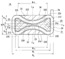
- FIGS. 2 and 5 are cross-sectional views of the reactor 1A cut along a plane orthogonal to the axial direction of the coil 2A.
- a reactor 1A includes a coil 2A including one cylindrical winding portion 20 formed by winding a winding 2w as shown in FIG. 1, and a magnetic core 3A disposed inside and outside the coil 2A. Is provided.
- the magnetic core 3 ⁇ / b> A includes a middle leg portion 31 disposed on the inner periphery of the winding portion 20 of the coil 2 ⁇ / b> A and two sides sandwiching the middle leg portion 31 disposed on the outer periphery of the winding portion 20.
- Two connecting portions 34 and 35 (FIGS.
- the magnetic core 3A is an assembly obtained by deforming a pair of E-shaped split cores (FIG. 4).
- Reactor 1A of this example is installed so that the axial direction of winding part 20 (or the axial direction of middle leg part 31) is parallel to the mounting surface of an installation target (not shown) such as a converter case. Used in horizontal form.
- the reactor 1A of Embodiment 1 includes the coil 2A of Embodiment 1 having a specific shape in which a part of the cylindrical winding portion 20 is recessed inward as shown in FIG. Further, the reactor 1A according to the first embodiment is provided with a portion (an overhanging portion 31p) that is not sandwiched between the side leg portions 32 and 33 in the middle leg portion 31 as shown in FIG. 2, and as shown in FIG.
- the magnetic core 3 ⁇ / b> A according to the first embodiment having a specific shape in which a part of the leg portion 31 is recessed inward and the side leg portions 32 and 33 protrude toward the recess of the middle leg portion 31 is provided. Further, as shown in FIG.
- the reactor 1 ⁇ / b> A has the above-described recessed portion (coil recessed portions 22, 23) in the winding portion 20 side of the recessed portion (core recessed portions 312, 313) of the middle leg portion 31.
- the portions sandwiched between the protruding portions (convex surfaces 320, 330) of the leg portions 32, 33 are covered with the magnetic core 3A, and the portions other than the recessed portion of the winding portion 20 are exposed portions not covered with the magnetic core 3A.
- each component will be described in detail.
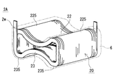
- the coil 2A of the first embodiment includes a cylindrical winding part 20 in which one winding 2w is spirally wound.
- the winding part 20 is provided with two coil recessed parts 22 and 23 provided so that the dent directions are opposite to each other toward the inner space surrounded by the inner peripheral surface thereof.
- the two coil recesses 22 and 23 are arranged to face each other. 2 and 3, the concave direction of the coil concave portion 22 is downward, the concave direction of the coil concave portion 23 is upward, and the concave portion is concave in the opposite direction at the same position in the width direction of the winding portion 20 (left and right direction in FIG. 2). Indicates the case.
- the winding portion 20 in this example has a horizontally long appearance that is enclosed in a horizontally long rectangular parallelepiped.
- the winding portion 20 has a long side portion of the horizontally long rectangular parallelepiped cylindrical body that is recessed toward the inside, and a center portion in the width direction is constricted, and the height increases as the distance from the center portion in the width direction increases. It is a ribbon-like cylinder that grows.
- the coil recesses 22, 23 are formed by using the inner space as the location where the middle leg 31 is disposed and the coil recesses 22, 23 as locations where the side legs 32, 33 are disposed. It is sandwiched between the middle leg portion 31 and the side leg portions 32 and 33, and portions other than the coil recess portions 22 and 23 are exposed from the magnetic core 3A.
- the winding 2w in this example is a covered wire including a conductor wire made of copper or the like and an insulating coating made of an insulating material such as polyamideimide covering the outer periphery of the conductor wire, and a rectangular wire having a rectangular cross-sectional shape. It is.
- the winding part 20 of this example is an edgewise coil.
- the winding 2w can be a wire having various shapes such as a round wire. When a rectangular wire edgewise coil is used as in this example, the space factor is increased and the size can be reduced (especially, the length can be easily reduced) as compared to a round wire coil. It is easy to make the outer peripheral surface of the turning part 20 smooth.
- the coil recesses 22 and 23 are formed as arcuate surfaces, and in the installed state, the installation surfaces 235 and 235 located below, the opposing surfaces 225 and 225 located above and facing the installation surface 235, and the width direction
- the side surfaces located on both sides are formed by flat surfaces (see FIG. 2).
- FIG. 3 illustrates a case where each end of the winding 2w is drawn upward so as to be separated from the winding part 20, the drawing direction, the drawing length, and the like can be changed as appropriate.
- the coil recesses 22 and 23 in this example are both arc-shaped (FIG. 2), but can be changed as appropriate. If it is circular arc like this example, the square part in the winding part 20 can be reduced, and it is easy to manufacture the coil 2A. In addition, it is expected that the magnetic core 3A corresponding to the winding portion 20 can be reduced in the angular portion, so that cracks and the like are not easily generated, and the assembling workability is excellent.
- the coil recesses 22 and 23 in this example have the same shape and the same size as shown in FIG. 2, the formation positions in the width direction are equal, and the formation position in the height direction is set to the center line L H in the height direction.
- the center is symmetrical. Therefore, the end surface shape and cross-sectional shape of the winding portion 20 is symmetrical about the center line L W in the width direction, and is symmetrical about the center line L H in the height direction.
- the shape and size of the coil recesses 22 and 23 (bending radius, protruding height to the inside of the winding part 20, etc.), the formation position, etc. are different, and the end face shape and the cross-sectional shape of the winding part 20 are non-linear.
- each coil recessed part 22 and 23 the space
- the inner peripheral surfaces of the coil recesses 22 and 23 are not in contact with each other, and a predetermined gap H 2 (here, the shortest distance between the coil recesses 22 and 23) is provided at the center of the winding portion 20 in the width direction.
- the opening widths W 22 and W 23 of the coil recesses 22 and 23 are about 20% to 90% of the width W 2 of the winding part 20, and the maximum depths H 22 and H 23 of the coil recesses 22 and 23 are windings.
- the height H of the portion 20 may be about 10% or more and less than 50%.
- the ratio of the long side to the short side of the virtual rectangle exceeds 1.
- the installation height of the reactor 1A tends to be relatively small.
- the ratio is too large, the productivity of the coil 2 ⁇ / b> A is reduced, and therefore the ratio can be set to about 4.0 or less in consideration of manufacturability. If the absolute value of the short side length (height H) is small, the installation height can be further reduced.
- a manufacturing method of the coil 2A including the coil recesses 22 and 23 for example, a method of forming a cylindrical body including the coil recesses 22 and 23 by spirally winding the winding 2w, and winding the winding 2w spirally.
- a method of forming the coil recesses 22 and 23 by, for example, pressing a predetermined position of the cylindrical body after forming a rectangular cylindrical body or a cylindrical body can be used.
- the coil 2 ⁇ / b> A can include a resin mold portion 6 that covers at least a part of the outer periphery of the winding portion 20.
- the resin mold portion 6 that covers substantially the entire inside and outside of the winding portion 20 is indicated by a virtual line (two-dot chain line), but at least a part of the inner and outer peripheral surfaces and the end surface of the winding portion 20. It is also possible to adopt a form that is exposed without covering. For example, if the exposed part from the magnetic core 3 ⁇ / b> A in the winding part 20 is also exposed from the resin mold part 6, it is easy to improve heat dissipation.
- the electrical insulation between the coil 2A and the magnetic core 3A can be improved.
- the electrical insulation between the coil 2A and the magnetic core 3A can be enhanced by using the above-described covered wire as the winding 2w.
- Examples of the constituent material of the resin mold portion 6 include insulating resins such as thermoplastic resins and thermosetting resins.
- the thermoplastic resin include polyphenylene sulfide (PPS) resin, polytetrafluoroethylene (PTFE) resin, liquid crystal polymer (LCP), polyamide (PA) resin such as nylon 6 and nylon 66, polybutylene terephthalate (PBT) resin, and acrylonitrile. -Butadiene styrene (ABS) resin etc. are mentioned.
- Examples of the thermosetting resin include unsaturated polyester resins, epoxy resins, urethane resins, and silicone resins.
- the insulating resin can contain nonmagnetic and nonmetallic powders such as alumina and silica. In this case, heat dissipation and electrical insulation can be improved.
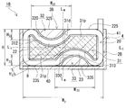
- the magnetic core 3 ⁇ / b> A has a middle leg portion 31 interposed between the side leg portions 32 and 33, which are in the order of the side leg portion 32, the middle leg portion 31, and the side leg portion 33. In an overlapped state, it is sandwiched between two connecting portions 34 and 35 that are arranged to face each other.
- the middle leg portion 31 includes two core concave portions 312 and 313 provided so that the dent directions are opposite to each other toward the inside, and the side leg portions 32 and 33 are respectively provided with the core concave portions 312 and 313.
- projecting surfaces 320 and 330 that are arranged with predetermined gaps between the core recesses 312 and 313.
- the two core concave portions 312 and 313 are opposed to each other, and the two convex surfaces 320 and 330 are opposed to each other.
- the concave direction of the core concave portion 312 and the protruding direction of the convex surface 320 are downward
- the concave direction of the core concave portion 313 and the convex direction of the convex surface 330 are upward, and are opposite at the same position in the width direction in the cross section of the magnetic core 3A.
- the case where the core concave portions 312 and 313 are recessed in the direction of, and the convex surfaces 320 and 330 protrude is shown.
- the magnetic core 3A of this example has a horizontally long appearance that is enclosed in a horizontally long rectangular parallelepiped (FIG. 1).
- the middle leg part 31 includes an interposition part 31d sandwiched between the two side leg parts 32 and 33 and an overhanging part 31p not sandwiched between the two side leg parts 32 and 33.
- the point including the overhanging portion 31p is one of the differences from the conventional E-shaped magnetic core in which the width of the middle leg is equal to or less than the width of the side leg.
- the overhanging portion 31p is shown with cross hatching so that it can be easily understood.
- the gap between the core concave portion 312 and the convex surface 320 is used as the location where the coil concave portion 22 is arranged
- the gap between the core concave portion 313 and the convex surface 330 is used as the location where the coil concave portion 23 is arranged
- the protruding portion 31p of the middle leg portion 31 is used. Is a place other than the coil recesses 22 and 23 in the winding part 20.
- the coil recesses 22 and 23 are covered with the magnetic core 3A, and portions other than the coil recesses 22 and 23 are exposed from the magnetic core 3A (FIGS. 1 and 2). 2).
- the magnetic core 3 ⁇ / b> A can include a molded body of a composite material including magnetic powder and resin.
- the particles of the magnetic powder include particles composed of soft magnetic metals and soft magnetic non-metals, and coated particles including an insulating coating composed of phosphate or the like on the outer periphery of the soft magnetic metal particles.
- the soft magnetic metal include iron group metals such as pure iron and iron base alloys (Fe—Si alloy, Fe—Ni alloy, etc.), and examples of the soft magnetic nonmetal include ferrite.
- the content of the magnetic powder in the composite material is 30% by volume to 80% by volume, and the content of the resin is 10% by volume to 70% by volume.
- the content of the magnetic powder can be 50% by volume or more, further 55% by volume or more, and 60% by volume or more.
- the content of the magnetic powder can be 75% by volume or less, further 70% by volume or less, and the resin content can be more than 30% by volume.
- the resin in the composite material examples include the thermosetting resin, the thermoplastic resin, the room temperature curable resin, and the low temperature curable resin described in the section of the resin mold portion 6 described above.
- BMC Bulk molding compound in which calcium carbonate or glass fiber is mixed with unsaturated polyester, millable silicone rubber, millable urethane rubber, or the like can also be used.
- a composite material containing non-magnetic and non-metallic powder such as alumina or silica can be obtained.
- the content of the non-magnetic and non-metallic powder is 0.2% by mass or more and 20% by mass or less, further 0.3% by mass or more and 15% by mass or less, and 0.5% by mass or more and 10% by mass or less.
- the molded body of the composite material can be manufactured by an appropriate molding method such as injection molding or cast molding.
- an appropriate molding method such as injection molding or cast molding.
- the coil 2A is housed in a molding die or case 4 (FIG. 5) and the composite material in a fluid state is filled into the inside and outside of the coil 2A, an integrally formed magnetic core 3A can be manufactured.
- a mold having an appropriate shape is used, it is possible to manufacture a split core piece composed of a composite material molded body.
- a molded body of a composite material can be easily molded even in a complicated shape, and is excellent in manufacturability.
- the magnetic core 3A can include a compacted body containing magnetic powder.
- a compacted body containing magnetic powder typically, a mixed powder containing magnetic powder and a binder is compression-molded into a predetermined shape, and further subjected to heat treatment after molding.
- the binder a resin or the like can be used, and the content thereof is about 30% by volume or less. When heat treatment is performed, the binder disappears or becomes a heat-denatured product.
- a mold having an appropriate shape it is possible to manufacture a split core piece composed of a compacted body.
- the compacted body has a higher content of magnetic powder than the compacted body of the composite material, and can easily construct a magnetic core having a high saturation magnetic flux density.
- the magnetic core 3A can include a laminate in which soft magnetic plates such as silicon steel plates are laminated, a sintered body such as a ferrite core, and the like.
- the magnetic core 3A can be provided with a gap material or an air gap.
- the gap material include a material composed of a nonmagnetic material such as alumina, a material composed of a mixture of a magnetic material and a nonmagnetic material, and a material having a lower relative magnetic permeability than a molded body such as a split core piece.
- a magnetic gap such as a gap material or an air gap can be omitted or the magnetic gap can be reduced. In this case, it is easy to reduce the loss caused by the leakage magnetic flux in the magnetic gap portion, the coil 2A and the magnetic core 3A can be arranged close to each other, and the size can be easily reduced.
- the magnetic core 3A can be an integrally molded product.
- the composite material can be easily manufactured as described above.
- the coil 2A including the resin mold portion 6 is used, the shape of the coil 2A can be easily maintained.
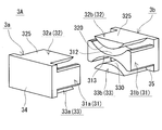
- FIG. 4 is similar to a state in which the magnetic core 3A, which is an integrally molded product, is cut along a plane perpendicular to the axial direction of the middle leg portion 31 and the cut pieces are separated.
- the magnetic core 3A can be a combination of a plurality of divided core pieces.
- the number of divisions, the shape of each divided core piece, the constituent material, and the like can be selected as appropriate.
- FIG. 4 shows a configuration in which a pair of split core pieces 3a and 3b are combined.
- One split core piece 3a is erected from one connecting portion 34, the connecting portion 34, and forms a middle leg piece 31a that forms part of the middle leg portion 31 and a part of each side leg portion 32, 33.
- the other split core piece 3b is erected from the other connecting part 35 and the connecting part 35, and forms the other part of the middle leg part 31b and the other part of each side leg part 32, 33.
- 3A of magnetic cores contain the split core piece comprised from a different material (For example, the form containing the split core piece comprised from the molded object of a composite material, and the divided core piece comprised from a compacting body etc.) Any form in which all the divided core pieces are made of the same material can be used.
- the middle leg portion 31 of this example is a ribbon-like columnar body in which the regions on the long sides of the horizontally long rectangular parallelepiped are recessed toward the inside, and the height increases as the distance from the central portion in the width direction increases. It is.
- the recessed portions are the core recesses 312 and 313.
- the middle leg portion 31 includes an arcuate surface that forms the core recesses 312 and 313 and a side surface that is disposed on both sides in the width direction and is configured by a rectangular plane. Each arcuate surface has the same shape and the same size.
- the side leg portions 32 and 33 in this example have the same shape and the same size, arc-shaped convex surfaces 320 and 330 along the core concave portions 312 and 313, and columnar shapes having a dome-shaped end surface and a cross section. Is the body.
- the side leg portion 33 arranged on the installation target side has an installation surface 335 constituted by a rectangular plane (FIG. 2).
- the side leg portion 32 disposed on the side away from the installation target is disposed to face the installation surface 335 and has a facing surface 325 configured by a rectangular plane.
- the connecting portions 34 and 35 in this example are thin rectangular parallelepipeds having the same shape and the same size, and have the same width as the width W 3 (FIG. 2) of the middle leg portion 31 and the height H of the winding portion 20 (FIG. 2). ).
- the side surfaces of the connecting portions 34 and 35 and the side surface of the middle leg portion 31 are provided flush with each other (FIG. 4).
- the installation surface (the lower surface in FIGS. 2 and 4) of the coupling portions 34 and 35 and the installation surface 335 (FIG. 2) of the side leg portion 33 are provided flush with each other.
- the facing surface (upper surface in FIGS. 2 and 4) that is disposed to face the installation surface of the coupling portions 34 and 35 is flush with the facing surface 325 (FIG.
- the magnetic core 3A of this example the cross-sectional shape (the split core piece 3a, similarly edge shapes of 3b) is symmetrical about the center line L W in the width direction as shown in FIG. 2, and high it is symmetrical about the center line L H direction is.
- the core recesses 312 and 313 and the convex surfaces 320 and 330 in this example are arcuate, but can be changed as appropriate.
- the shape and size of the core recesses 312 and 313 and the convex surfaces 320 and 330 are typically set to the shape and size of the coil 2A to be assembled to the magnetic core 3A, particularly the coil recesses 22 and 23.
- the magnetic core 3A is an integrally molded product, if the magnetic core 3A is manufactured along the coil 2A, the magnetic core 3A including the core concave portions 312 and 313 and the convex surfaces 320 and 330 corresponding to the coil concave portions 22 and 23, and can do.
- a gap having a size that can accommodate the coil recesses 22 and 23 between the core recess 312 and the convex surface 320 and between the core recess 313 and the convex surface 330 (for example, The shape, size, arrangement position, etc. of the middle leg portion 31 and the side leg portions 32, 33 may be adjusted so that a gap slightly larger than the width of the winding 2w is formed.
- the core concave portions 312 and 313 and the convex surfaces 320 and 330 are arc-shaped as in this example, the angular portions can be reduced, and cracks and the like occur when assembled with the coil 2A. It is difficult and is expected to be excellent in assembly workability.
- the middle leg portion 31 of this example has a width W 3 longer than the widths of the side leg portions 32 and 33.
- a central portion (intervening portion 31d) in the width direction of the middle leg portion 31 is sandwiched between side leg portions 32 and 33 positioned vertically in FIG. Both end portions in the width direction of the middle leg portion 31 (projecting portions 31p) are not sandwiched between the side leg portions 32 and 33, and protrude in the width direction from the side leg portions 32 and 33.
- the intervening portion 31d refers to both the leg portions 32 and 33 in the middle leg portion 31 when projected in a direction orthogonal to the facing surface 325 of the side leg portion 32 (or the installation surface 335 of the side leg portion 33). Let it be a part which overlaps and let the part which does not overlap be the overhanging part 31p.
- the intervening part 31d in this example is a straight line (indicated by a two-dot chain line in FIG. 2) that is orthogonal to the opposing surface 325 and the installation surface 335 of the side legs 32 and 33 and passes through the end portions in the width direction of the side legs 32 and 33. It is an area sandwiched by (shown).
- the formation length in the width direction at the intervening portion 31d and the overhanging portion 31p can be appropriately selected.
- the greater the formation length of the intervening portion 31d the easier it is to reduce the increase in loss due to leakage magnetic flux.
- the larger the formation location of the overhanging portion 31p the larger the region arranged along the overhanging portion 31p in the winding portion 20, and the easier it is to secure the exposed portion, and the easier it is to improve the heat dissipation.
- the formation length of the intervening portions 31d for example, 80% lower than about 1% or more of the width W 3 of the center leg 31, the formation length of the overhang portion 31p (2 places in total length), for example,
- the width W 3 of the middle leg portion 31 can be about 20% or more and 80% or less.
- the horizontally long magnetic core 3A is quantitatively assumed to be a rectangle containing a cross section obtained by cutting the magnetic core 3A along a plane orthogonal to the axial direction of the middle leg portion 31, the short side of this virtual rectangle is assumed.
- the ratio of the long side to the width exceeds 1.
- the installation height of the reactor 1A tends to be relatively small.
- the ratio is too large, the productivity of the magnetic core 3A is reduced, and therefore the ratio can be set to about 4.0 or less in consideration of manufacturability. If the absolute value of the short side length (height H) is small, the installation height can be further reduced.
- a reactor 1A according to the first embodiment includes the coil 2A according to the first embodiment described above and the magnetic core 3A according to the first embodiment.
- the coil recesses 22 and 23 in the winding part 20 of the coil 2A have the core recesses 312 and 313 of the middle leg part 31 and the convex surfaces 320 and 330 of the side leg parts 32 and 33, respectively.
- the magnetic flux from the winding part 20 is sandwiched between the middle leg part 31 and the side leg parts 32 and 33. Is easy to pass through the magnetic core 3A, and it is easy to reduce the magnetic flux interlinking with the winding part 20.
- the exposed portion of the winding portion 20 from the magnetic core 3A is a portion that surrounds the protruding portion 31p of the middle leg portion 31, and includes an installation surface 235, a facing surface 225, and side surfaces, and these surfaces dissipate heat to the outside. Available as a face.
- the side surface can be used as a heat radiating surface.
- the side leg portions 32 and 33 in this example have a surface that is flush with a part of the exposed portion of the winding portion 20 from the magnetic core 3A.
- the installation surface 335 of the side leg portion 33 is flush with the installation surface 235 of the winding unit 20. Therefore, the installation surface of the reactor 1 ⁇ / b> A includes the winding part 20, the side legs 33 and the connecting parts 34 and 35 of the magnetic core 3 ⁇ / b> A.
- the installation surface 235 of the winding unit 20 can be used as a heat dissipation surface to dissipate heat to the installation target.
- the facing surface 325 of the side leg portion 32 and the facing surface 225 of the winding portion 20 are also flush. Therefore, reactor 1A has a flat rectangular parallelepiped appearance as a whole as shown in FIG.
- the reactor 1A can be provided with a case 4 that houses an assembly including a coil 2A and a magnetic core 3A as shown in FIG.
- the case 4 includes a box body that includes a bottom portion 40 that supports the installation surface of the reactor 1 ⁇ / b> A and a wall portion 41 that is erected from the bottom portion 40. If the shape and size of the case 4 is a shape and size corresponding to the assembly, it is easy to reduce the size even if the case 4 is provided. If the constituent material of the case 4 is a metal such as aluminum or aluminum alloy, the case 4 can be used as a heat dissipation path, and effects such as excellent strength and easy mechanical protection can be expected. In FIG.
- the shape and size are such that the assembly installation surface is close to the inner bottom surface of the case 4, and the side surface of the assembly (here, the side surface of the winding portion 20) is close to the inner wall surface of the case 4.
- a metal case 4 is shown.
- the reactor 1 ⁇ / b> A can include a heat dissipation layer 9 between the assembly including the coil 2 ⁇ / b> A and the magnetic core 3 ⁇ / b> A and the inner bottom surface of the case 4 as shown in FIG. 5.
- the heat dissipating layer 9 is made of a material having excellent heat dissipating properties, and enhances the heat conductivity from the coil 2A to the case 4. Specific examples of the material include those containing a filler (nonmagnetic and nonmetallic powder such as alumina) having excellent heat dissipation and a resin, and a sheet or the like may be used.
- the heat dissipation layer 9 includes an adhesive, the assembly can be fixed to the case 4 by the heat dissipation layer 9. At least one of the case 4 and the heat dissipation layer 9 may be omitted.
- the reactor 1A according to the first embodiment includes various in-vehicle converters (typically DC-DC converters) and air conditioner converters mounted on vehicles such as hybrid vehicles, plug-in hybrid vehicles, electric vehicles, and fuel cell vehicles. It can be used as a component of power converters and converters.
- the reactor 1A of the first embodiment is used for a large current (100A or more, more preferably 150A or more), and can be suitably used when it is required to have excellent heat dissipation and a low profile is desired.
- the coil 2A of the first embodiment and the magnetic core 3A of the first embodiment can be used for components such as the reactor 1A.
- the reactor 1A according to the first embodiment has a horizontally long appearance, and the installation height can be lowered when a horizontally placed form is adopted.
- the reactor 1A of the first embodiment includes the coil 2A of the first embodiment including the coil concave portions 22 and 23 and the magnetic core 3A of the first embodiment including the core concave portions 312 and 313 and the convex surfaces 320 and 330.
- the installation height is lower, and the loss is low and the heat dissipation is excellent.
- the coil concave portions 22 and 23 of the winding portion 20 are arranged between the core concave portions 312 and 313 of the middle leg portion 31 and the convex surfaces 320 and 330 of the side leg portions 32 and 33 in the magnetic core 3A, in the height direction. When viewed, a part of the winding part 20 and a part of the magnetic core 3A are arranged in an overlapping manner, so that the height can be reduced.
- the protruding portion 31p is provided in the middle leg portion 31 of the magnetic core 3A, and the portion surrounding the protruding portion 31p in the winding portion 20 is defined as an exposed portion that is not covered by the magnetic core 3A. It can be used for heat dissipation points.
- the middle leg portion 31 in the magnetic core 3A includes the protruding portion 31p and the intervening portion 31d, the magnetic path area can be secured and the leakage magnetic flux can be reduced. As a result, the magnetic flux interlinking with the winding part 20 can be reduced.
- the reactor 1A of this example has the following effects.
- A Since a part of the exposed part of the winding part 20 and a part of the side leg parts 32 and 33 are flush with each other, the height H can be easily reduced and the installation height can be further reduced.
- B Since the exposed part of the winding part 20 includes the three surfaces of the installation surface 235, the opposing surface 225, and a side surface, each surface can be made into a heat radiation surface, and heat dissipation can be improved more.
- the coil 2A is symmetrical with the coil recesses 22 and 23 facing each other, and the magnetic core 3A is symmetrical with the core recesses 312 and 313 and the convex surfaces 320 and 330 facing each other. In addition to excellent manufacturability of the core 3A, it is also excellent in electromagnetic balance.
- FIG. 6 is a cross-sectional view of the reactor 1B cut along a plane orthogonal to the axial direction of the coil 2B.
- the basic configuration of the reactor 1B of the second embodiment is the same as that of the reactor 1A of the first embodiment. That is, the reactor 1 ⁇ / b> B has a horizontally long appearance, and the installation height can be lowered when it is in a horizontally placed form.
- the reactor 1B includes the coil 2B according to the second embodiment in which the winding portion 20 includes the coil concave portions 22 and 23, the core leg portions 31 and 313 in the middle leg portion 31, and the convex surfaces 320 and 330 in the side leg portions 32 and 33.
- the magnetic core 3B of Embodiment 2 is provided.
- the main difference between the reactor 1B of the second embodiment and the first embodiment is that the coil concave portions 22 and 23 are arranged so as to be shifted from each other in the width direction of the winding portion 20 and correspond to the shape of the winding portion 20.
- the concave portions 312 and 313 and the convex surfaces 320 and 330 are also arranged so as to be shifted in the width direction of the winding portion 20.
- the coil recess 22 is positioned closer to one side (the left side in FIG. 6) of the winding portion 20 and the coil recess 23 is positioned closer to the other side (the right side in FIG. 6).
- the two coil recesses 22 and 23 are located almost diagonally. Therefore, although part of the coil recesses 22 and 23 face each other, the other parts do not face each other.
- FIG. 6 shows a case where the recess direction of the coil recess 22 is downward, the recess direction of the coil recess 23 is upward, and the winding recess 20 is recessed in the opposite direction at a position shifted to the left and right in the width direction.
- the installation surface 235 and the facing surface 225 of the coil 2B are likely to have a larger area than the coil 2A of the first embodiment.
- the coil 2A of the first embodiment includes relatively small installation surfaces 235 and 235 and opposing surfaces 225 and 225 on both sides of the coil recesses 22 and 23 as shown in FIG.
- the installation surface 235 and the opposing surface 225 are each configured by one continuous surface, so that a large area can be secured. From this point, further improvement in heat dissipation can be expected.
- the core recess 312 is positioned closer to one side in the width direction of the middle leg 31 (leftward in FIG. 6), and the convex surface of the side leg 32 corresponds to the position of the core recess 312. 320 is also located.
- the core concave portion 313 is located on the other side in the width direction of the middle leg portion 31 (right side in FIG. 6), and the convex surface 330 of the side leg portion 33 is also located corresponding to the position of the core concave portion 313.
- Both core recesses 312 and 313 are located substantially diagonally, and correspondingly, both convex surfaces 320 and 330 are also located substantially diagonally.
- the overhanging portion 31p is shown with cross-hatching so that it can be easily understood. Since the formation positions of the core concave portions 312 and 313 are shifted in the width direction, the width of the interposition portion 31d sandwiched between the two side leg portions 32 and 33 in the middle leg portion 31 is compared with the magnetic core 3A of the first embodiment. The protruding portions 31p, 31p of the middle leg 31 that are not sandwiched between the two side legs 32, 33 are larger than the magnetic core 3A of the first embodiment. Therefore, it is easy to ensure a large exposed portion of the winding portion 20 arranged so as to surround the overhanging portion 31p, and heat dissipation can be improved.
- the reactor 1B according to the second embodiment includes the coil 2B according to the second embodiment including the coil concave portions 22 and 23, and the magnetic core 3B according to the second embodiment including the core concave portions 312 and 313 and the convex surfaces 320 and 330. Therefore, the installation height is low, low loss and excellent heat dissipation. In particular, the reactor 1B of the second embodiment is more excellent in heat dissipation because it is easy to ensure a large exposed portion of the winding part 20 as described above.
- a sensor for measuring a physical quantity of the reactor such as a temperature sensor, a current sensor, a voltage sensor, and a magnetic flux sensor is provided.
- a heat radiating plate is provided at an exposed portion of the winding unit 20 (for example, a side surface of the winding unit 20).
- an insulating interposed member such as a bobbin is provided.
- a heat fusion resin part (not shown) for joining adjacent turns constituting the winding part 20 is provided.
- the case 4 includes a sealing resin that seals the assembly including the coil 2A and the magnetic core 3A.
- the present invention is not limited to these exemplifications, but is defined by the scope of the claims, and is intended to include all modifications within the scope and meaning equivalent to the scope of the claims.
- it can be set as an installation form other than the horizontal installation form.
- the installation mode in which the axial direction of the winding part 20 is orthogonal to the installation surface to be installed is rotated 90 degrees right or left from the state shown in FIG.
- the installation form etc. which become an installation surface are mentioned.
- These forms can be a low-loss reactor or the like. Moreover, these forms are expected to be excellent in heat dissipation depending on the arrangement state of the cooling mechanism.
- the reactor having a low installation height, low loss, and excellent heat dissipation can be configured as follows.
- [Appendix 1] A coil having a cylindrical winding portion formed by winding a winding; A middle leg portion arranged on the inner circumference of the winding portion, two side leg portions arranged on the outer circumference of the winding portion and sandwiching the middle leg portion, and sandwiching the middle leg portion and both side leg portions, A magnetic core comprising two coupling parts for coupling these,
- the winding part is Toward the inner space surrounded by the inner peripheral surface, two coil recesses provided between the middle leg part and the side leg part, so that the dent directions are opposite to each other, An exposed portion that is exposed without being covered by the magnetic core,
- the middle leg is An overhanging portion not sandwiched between the two side legs, Two core recesses provided along the coil recess and recessed toward the inside of the middle leg,
- Each side leg is A reactor including a convex surface that protrudes toward each core recess and sandwiches
Landscapes
- Engineering & Computer Science (AREA)
- Power Engineering (AREA)
- Coils Of Transformers For General Uses (AREA)
- Insulating Of Coils (AREA)
- Dc-Dc Converters (AREA)
Abstract
巻線が巻回されてなる筒状の巻回部を備え、前記巻回部は、その内周面に囲まれる内側空間に向かって、凹み方向が互いに逆向きになるように設けられた二つのコイル凹部を備えるコイル。
Description
本発明は、コイル、磁性コア、及びリアクトルに関するものである。
本出願は、2016年09月21日付の日本国出願「特願2016-184615」に基づく優先権を主張し、上記日本国出願に記載された全ての記載内容を援用するものである。
本出願は、2016年09月21日付の日本国出願「特願2016-184615」に基づく優先権を主張し、上記日本国出願に記載された全ての記載内容を援用するものである。
電圧の昇圧動作や降圧動作を行う回路の部品の一つに、リアクトルがある。特許文献1の図4,図5は、車載コンバータ用のリアクトルとして、巻線を螺旋状に巻回してなる一つの矩形筒状の巻回部を備えるコイルと、一対のE字状の分割コアを組み合わせてなる磁性コアとを備えるものを開示する。この磁性コアは、巻回部の内周に配置される中脚(内側コア部31)と、巻回部の外周に配置されて中脚を挟む一対の側脚と、中脚及び両側脚を挟み、これらを連結する二つの連結部とを備える。
本開示のコイルは、
巻線が巻回されてなる筒状の巻回部を備え、
前記巻回部は、その内周面に囲まれる内側空間に向かって、凹み方向が互いに逆向きになるように設けられた二つのコイル凹部を備える。
巻線が巻回されてなる筒状の巻回部を備え、
前記巻回部は、その内周面に囲まれる内側空間に向かって、凹み方向が互いに逆向きになるように設けられた二つのコイル凹部を備える。
本開示の磁性コアは、
コイルの巻回部の内周に配置される中脚部と、前記巻回部の外周に配置されて前記中脚部を挟む二つの側脚部と、前記中脚部及び両側脚部を挟み、これらを連結する二つの連結部とを備え、
前記中脚部は、
前記二つの側脚部に挟まれない張出箇所を含み、
前記中脚部の内部に向かって、凹み方向が互いに逆向きになるように設けられた二つのコア凹部を備え、
各側脚部は、
各コア凹部に向かって突出し、前記各コア凹部との間に所定の隙間を設けて配置される凸面を備える。
コイルの巻回部の内周に配置される中脚部と、前記巻回部の外周に配置されて前記中脚部を挟む二つの側脚部と、前記中脚部及び両側脚部を挟み、これらを連結する二つの連結部とを備え、
前記中脚部は、
前記二つの側脚部に挟まれない張出箇所を含み、
前記中脚部の内部に向かって、凹み方向が互いに逆向きになるように設けられた二つのコア凹部を備え、
各側脚部は、
各コア凹部に向かって突出し、前記各コア凹部との間に所定の隙間を設けて配置される凸面を備える。
本開示のリアクトルは、
上記の本開示のコイルと、上記の本開示の磁性コアとを備え、
各コイル凹部が前記中脚部の各コア凹部と前記各側脚部の凸面間に配置され、
前記巻回部における前記コイル凹部以外の箇所が前記磁性コアに覆われずに露出される。
上記の本開示のコイルと、上記の本開示の磁性コアとを備え、
各コイル凹部が前記中脚部の各コア凹部と前記各側脚部の凸面間に配置され、
前記巻回部における前記コイル凹部以外の箇所が前記磁性コアに覆われずに露出される。
[本開示が解決しようとする課題]
設置高さが低く、低損失で、放熱性にも優れるリアクトルが望まれている。また、このようなリアクトルを構築できるコイル及び磁性コアが望まれている。
設置高さが低く、低損失で、放熱性にも優れるリアクトルが望まれている。また、このようなリアクトルを構築できるコイル及び磁性コアが望まれている。
特許文献1の図4では、リアクトルを取り付ける設置対象の載置面に対してコイルの巻回部の軸方向が平行するようにリアクトルを設置対象に設置する形態(以下、横置き形態と呼ぶことがある)を示す。横置き形態では、巻回部の軸方向が設置対象の載置面に対して直交するようにリアクトルを設置する場合に比較して、特に巻回部のターン数が多い場合などでも、リアクトルにおける載置面からの高さ(以下、設置高さと呼ぶことがある)を低くできる。また、特許文献1の図4では、巻回部の外周面における設置対象側に位置する下面及びその対向位置にある上面を磁性コアで覆わず露出させ、巻回部の下面を設置対象の載置面に近接する。こうすることで、コイルの熱を設置対象に伝え易い上に巻回部の上面から周囲雰囲気にも放散し易く、放熱性に優れる。
しかし、特許文献1の図4に示すリアクトルに対して、更なる低背化を図ると、以下のように、損失の増大が懸念される。設置高さを低くするために、巻回部の端面形状を横長の長方形状に変更し、この横長の巻回部の形状に対応して、中脚を横長の長方形状に変更すると、中脚と側脚との中心間の距離が離れる。その結果、横長の巻回部において、中脚と側脚間に挟まれず、磁性コアに覆われない箇所の長さが長くなり、このような箇所に漏れ磁束が鎖交し易い。漏れ磁束の鎖交によって、コイルに生じる渦電流損の増大を招き得る。
上述の横長の巻回部に対して、例えば巻回部の長辺部を中脚と側脚とで挟み、巻回部の短辺部を露出させれば、上述の巻回部への磁束の鎖交を低減して、損失の増大を低減し易い。しかし、巻回部の長辺部と設置対象の載置面間に側脚が介在されるため、側脚の厚さ分だけ設置高さの増大を招く上に、コイルから設置対象への放熱性の低下も招く。
そこで、設置高さが低く、低損失で、放熱性にも優れるリアクトルを提供することを目的の一つとする。また、設置高さが低く、低損失で、放熱性にも優れるリアクトルなどを構築できるコイル、及び磁性コアを提供することを別の目的の一つとする。
[本開示の効果]
上記の本開示のコイル及び上記の本開示の磁性コアは、設置高さが低く、低損失で、放熱性にも優れるリアクトルなどを構築できる。上記の本開示のリアクトルは、設置高さが低く、低損失で、放熱性にも優れる。
上記の本開示のコイル及び上記の本開示の磁性コアは、設置高さが低く、低損失で、放熱性にも優れるリアクトルなどを構築できる。上記の本開示のリアクトルは、設置高さが低く、低損失で、放熱性にも優れる。
[本願発明の実施形態の説明]
最初に本願発明の実施態様を列記して説明する。
(1)本開示の一態様に係るコイルは、
巻線が巻回されてなる筒状の巻回部を備え、
前記巻回部は、その内周面に囲まれる内側空間に向かって、凹み方向が互いに逆向きになるように設けられた二つのコイル凹部を備える。
最初に本願発明の実施態様を列記して説明する。
(1)本開示の一態様に係るコイルは、
巻線が巻回されてなる筒状の巻回部を備え、
前記巻回部は、その内周面に囲まれる内側空間に向かって、凹み方向が互いに逆向きになるように設けられた二つのコイル凹部を備える。
上記のコイルによれば、設置高さが低く、低損失で、放熱性にも優れるリアクトルなどを構築できる。詳しくは以下の通りである。
上記のコイルは、巻回部のコイル凹部を磁性コアの配置箇所に利用できる。上記のコイルに磁性コア(特に後述の(5)の磁性コアなど)を組み付けて、コイル凹部に磁性コアの一部を配置すれば、コイル凹部と磁性コアの一部との重複配置によって、上記のコイルと磁性コアとを含む組物の大きさを小さくできる。従って、上記のコイルを利用することで、好ましくは横置き形態とすることで、設置高さが低いリアクトルなどを構築できる。
上記のコイルは、巻回部のコイル凹部を磁性コアの配置箇所とし、巻回部におけるコイル凹部以外の箇所を磁性コアに覆われない露出箇所とすれば、この露出箇所の少なくとも一部を設置対象の載置面に近接させたり、周囲雰囲気に曝したりすることなどができる。従って、上記のコイルを利用することで、放熱性に優れるリアクトルなどを構築できる。
上記のコイルは、巻回部のコイル凹部を磁性コアの配置箇所とし、コイル凹部を、磁性コアにおける巻回部内に配置される箇所とコイル凹部に配置される箇所とで挟むことができる。そのため、巻回部の端面形状が横長であり、コイル凹部が比較的長くても、漏れ磁束の鎖交に起因する損失を低減し易い。従って、上記のコイルを利用することで、低損失なリアクトルなどを構築できる。
(2)上記のコイルの一例として、
前記巻回部の端面を内包する長方形の短辺に対する長辺の比が1.5以上である形態が挙げられる。
前記巻回部の端面を内包する長方形の短辺に対する長辺の比が1.5以上である形態が挙げられる。
上記形態は偏平なコイルといえ、横長に設置できる。従って、上記形態は、設置高さがより低いリアクトルなどを構築できる。
(3)上記のコイルの一例として、
前記二つのコイル凹部は、対向配置される形態が挙げられる。
前記二つのコイル凹部は、対向配置される形態が挙げられる。
上記形態は、例えばコイル凹部が向かい合った対称形状とすることができ、非対称な場合と比較して、コイルを形成し易い上に、磁束をバランスよく磁性コアに流し易い。従って、上記形態は、設置高さが低く、低損失で、放熱性にも優れるリアクトルなどを構築できる上に、製造性にも優れ、電磁気的なバランスにも優れるリアクトルなどを構築できる。
(4)上記のコイルの一例として、
前記コイルの外周の少なくとも一部を覆う樹脂モールド部を備える形態が挙げられる。
前記コイルの外周の少なくとも一部を覆う樹脂モールド部を備える形態が挙げられる。
上記形態は、磁性コアや周囲部品などとの間の絶縁性を高められる。従って、上記形態は、設置高さが低く、低損失で、放熱性にも優れるリアクトルなどを構築できる上に、絶縁性にも優れる。
(5)本開示の一態様に係る磁性コアは、
コイルの巻回部の内周に配置される中脚部と、前記巻回部の外周に配置されて前記中脚部を挟む二つの側脚部と、前記中脚部及び両側脚部を挟み、これらを連結する二つの連結部とを備え、
前記中脚部は、
前記二つの側脚部に挟まれない張出箇所を含み、
前記中脚部の内部に向かって、凹み方向が互いに逆向きになるように設けられた二つのコア凹部を備え、
各側脚部は、
各コア凹部に向かって突出し、前記各コア凹部との間に所定の隙間を設けて配置される凸面を備える。
コイルの巻回部の内周に配置される中脚部と、前記巻回部の外周に配置されて前記中脚部を挟む二つの側脚部と、前記中脚部及び両側脚部を挟み、これらを連結する二つの連結部とを備え、
前記中脚部は、
前記二つの側脚部に挟まれない張出箇所を含み、
前記中脚部の内部に向かって、凹み方向が互いに逆向きになるように設けられた二つのコア凹部を備え、
各側脚部は、
各コア凹部に向かって突出し、前記各コア凹部との間に所定の隙間を設けて配置される凸面を備える。
上記の磁性コアによれば、設置高さが低く、低損失で、放熱性にも優れるリアクトルなどを構築できる。詳しくは以下の通りである。
上記の磁性コアは、中脚部のコア凹部と側脚部の凸面間の隙間をコイルの巻回部の配置箇所に利用できる。上記の磁性コアにコイル(特に上述の(1)のコイルなど)を組み付けて、中脚部を巻回部内に挿通配置すると共に上記の隙間に巻回部の一部を配置すれば、磁性コアの一部と巻回部の一部との重複配置によって、上記の磁性コアとコイルとを含む組物の大きさを小さくできる。従って、上記の磁性コアを利用することで、好ましくは中脚部の軸方向が設置対象の載置面に平行するように設置する形態(横置き形態に相当)とすることで、設置高さが低いリアクトルなどを構築できる。
上記の磁性コアは、中脚部のコア凹部と側脚部の凸面間の隙間を巻回部の一部の配置箇所とし、中脚部の張出箇所を囲むように巻回部の他部を配置すれば、この巻回部の他部を磁性コアに覆われない露出箇所とすることができる。この露出箇所の少なくとも一部を設置対象の載置面に近接させたり、周囲雰囲気に曝したりすることなどができる。従って、上記の磁性コアを利用することで、放熱性に優れるリアクトルなどを構築できる。
上記の磁性コアは、中脚部に凹んだ部分を含むものの張出箇所を備えるため、所定の磁路面積を確保できる。また、中脚部の各コア凹部を埋めるように各側脚部が設けられ、中脚部と側脚部とが近接される部分を含むため、漏れ磁束を低減できる。そのため、磁性コアの横断面(後述)における外形が横長である場合でも、中脚部のコア凹部と側脚部の凸面間の隙間に巻回部の一部を配置すれば、漏れ磁束の鎖交に起因する損失を低減でき、低損失なリアクトルなどを構築できる。
(6)上記の磁性コアの一例として、
前記中脚部の軸方向に直交する平面で前記磁性コアを切断した横断面を内包する長方形の短辺に対する長辺の比が1.5以上である形態が挙げられる。
前記中脚部の軸方向に直交する平面で前記磁性コアを切断した横断面を内包する長方形の短辺に対する長辺の比が1.5以上である形態が挙げられる。
上記形態は偏平な磁性コアといえ、横長に設置できる。従って、上記形態は、設置高さがより低いリアクトルなどを構築できる。
(7)上記の磁性コアの一例として、
前記二つのコア凹部が対向配置されると共に、前記二つの凸面が対向配置される形態が挙げられる。
前記二つのコア凹部が対向配置されると共に、前記二つの凸面が対向配置される形態が挙げられる。
上記形態は、例えばコア凹部が向かい合い、その外側に凸面が向かい合った対称形状とすることができ、非対称な場合と比較して、磁性コアを形成し易い上に、磁束をバランスよく通過させ易い。従って、上記形態は、設置高さが低く、低損失で、放熱性にも優れるリアクトルなどを構築できる上に、製造性にも優れ、電磁気的なバランスにも優れるリアクトルなどを構築できる。
(8)上記の磁性コアの一例として、
磁性粉末と樹脂とを含む複合材料の成形体、及び磁性粉末を含む圧粉成形体の少なくとも一方を備える形態が挙げられる。
磁性粉末と樹脂とを含む複合材料の成形体、及び磁性粉末を含む圧粉成形体の少なくとも一方を備える形態が挙げられる。
上記形態は、複合材料の成形体から構成される一体成形物や、複合材料の成形体及び圧粉成形体の少なくとも一方から構成される複数の分割コア片の組物とすることができ、材料の選択の自由度が高い。
(9)上記の磁性コアの一例として、
一対の分割コア片を組み合わせて構成され、
各分割コア片は、一方の前記連結部と、前記連結部から立設され、前記中脚部の一部を形成する中脚片及び前記各側脚部の一部を形成する二つの側脚片とを備える形態が挙げられる。
一対の分割コア片を組み合わせて構成され、
各分割コア片は、一方の前記連結部と、前記連結部から立設され、前記中脚部の一部を形成する中脚片及び前記各側脚部の一部を形成する二つの側脚片とを備える形態が挙げられる。
上記形態は、コイルと組み付け易く、組付部品点数も少ない。従って、上記形態は、設置高さが低く、低損失で、放熱性にも優れるリアクトルなどを構築できる上に、リアクトルなどを製造し易い。
(10)本開示の一態様に係るリアクトルは、
上記(1)から(4)のいずれか一つに記載のコイルと、上記(5)から(9)のいずれか一つに記載の磁性コアとを備え、
各コイル凹部が前記中脚部の各コア凹部と前記各側脚部の凸面間に配置され、
前記巻回部における前記コイル凹部以外の箇所が前記磁性コアに覆われずに露出される。
上記(1)から(4)のいずれか一つに記載のコイルと、上記(5)から(9)のいずれか一つに記載の磁性コアとを備え、
各コイル凹部が前記中脚部の各コア凹部と前記各側脚部の凸面間に配置され、
前記巻回部における前記コイル凹部以外の箇所が前記磁性コアに覆われずに露出される。
上記のリアクトルは、コイル凹部を備えるという特定の形状のコイルと、中脚部にコア凹部を備える及び側脚部に凸面を備えるという特定の形状の磁性コアとを備え、各コイル凹部が中脚部のコア凹部と側脚部の凸面間に配置される。コイル凹部と中脚部及び側脚部との重複配置によって、上記のリアクトルの大きさを小さくできる。また、上記のリアクトルは、巻回部の一部(主としてコイル凹部)を磁性コアに覆われる箇所とし、巻回部の他部(主としてコイル凹部以外)を磁性コアに覆われない露出箇所とする。そのため、上述のように巻回部や磁性コアが横長な外観を有する場合でも、漏れ磁束及びこれに起因する損失を低減できる上に、コイルの熱を効率よく放散できる。従って、上記のリアクトルは、好ましくは横置き形態とすることで設置高さを低くできる上に、低損失で、放熱性にも優れる。
(11)上記のリアクトルの一例として、
前記側脚部は、前記巻回部における前記磁性コアからの露出箇所の一部と面一な面を備える形態が挙げられる。
前記側脚部は、前記巻回部における前記磁性コアからの露出箇所の一部と面一な面を備える形態が挙げられる。
上記形態は、巻回部における磁性コアから出っ張った箇所が少なく、更に小型なリアクトルといえ、設置高さをより低くし易い。また、上記形態は、巻回部における面一な面を放熱面として利用すれば、放熱性により優れる。
[本願発明の実施形態の詳細]
以下、図面を参照して、本願発明の実施形態を具体的に説明する。図中の同一符号は同一名称物を示す。以下、図面に示すリアクトル、コイル、磁性コアについて、その下面を設置対象の載置面に配置される設置面とする場合を説明する。また、以下の説明では、リアクトルなどを設置対象に設置した状態において、コイルの巻回部の軸方向に沿った方向を長さ方向、巻回部の軸方向に直交する方向であって、設置対象の載置面に平行な方向を幅方向、載置面に直交する方向を高さ方向と呼ぶことがある。
以下、図面を参照して、本願発明の実施形態を具体的に説明する。図中の同一符号は同一名称物を示す。以下、図面に示すリアクトル、コイル、磁性コアについて、その下面を設置対象の載置面に配置される設置面とする場合を説明する。また、以下の説明では、リアクトルなどを設置対象に設置した状態において、コイルの巻回部の軸方向に沿った方向を長さ方向、巻回部の軸方向に直交する方向であって、設置対象の載置面に平行な方向を幅方向、載置面に直交する方向を高さ方向と呼ぶことがある。
[実施形態1]
図1から図5を参照して、実施形態1のリアクトル1A,コイル2A,磁性コア3Aを説明する。図2,図5は、リアクトル1Aをコイル2Aの軸方向に直交する平面で切断した横断面図である。
図1から図5を参照して、実施形態1のリアクトル1A,コイル2A,磁性コア3Aを説明する。図2,図5は、リアクトル1Aをコイル2Aの軸方向に直交する平面で切断した横断面図である。
(リアクトル)
<概要>
実施形態1のリアクトル1Aは、図1に示すように巻線2wが巻回されてなる一つの筒状の巻回部20を備えるコイル2Aと、コイル2Aの内外に配置される磁性コア3Aとを備える。磁性コア3Aは、図2に示すようにコイル2Aの巻回部20の内周に配置される中脚部31と、巻回部20の外周に配置されて中脚部31を挟む二つの側脚部32,33と、中脚部31及び両側脚部32,33を挟み、これら中脚部31及び側脚部32,33を連結する二つの連結部34,35(図1、図4)とを備える。磁性コア3Aは、端的にいうと、一対のE字状の分割コアを変形させた組物である(図4)。この例のリアクトル1Aは、コンバータケースなどの設置対象(図示せず)の載置面に対して巻回部20の軸方向(又は中脚部31の軸方向)が平行するように設置される横置き形態で使用される。
実施形態1のリアクトル1Aは、図3に示すように筒状の巻回部20の一部が内側に向かって凹んだ特定の形状である実施形態1のコイル2Aを備える。また、実施形態1のリアクトル1Aは、図2に示すように中脚部31に、側脚部32,33に挟まれない箇所(張出箇所31p)を備えると共に、図4に示すように中脚部31の一部が内側に向かって凹み、側脚部32,33が中脚部31の凹みに向かって突出するという特定の形状である実施形態1の磁性コア3Aを備える。更に、実施形態1のリアクトル1Aは、図2に示すように巻回部20における上述の凹み部分(コイル凹部22,23)を、中脚部31の凹み部分(コア凹部312,313)と側脚部32,33の突出部分(凸面320,330)とに挟まれて磁性コア3Aに覆われる箇所とし、巻回部20の凹み部分以外の箇所を磁性コア3Aに覆われない露出箇所とする。以下、構成要素ごとに詳細に説明する。
(コイル)
<概要>
実施形態1のコイル2Aは、図3に示すように1本の巻線2wが螺旋状に巻回されてなる筒状の巻回部20を備える。巻回部20は、その内周面に囲まれる内側空間に向かって、凹み方向が互いに逆向きになるように設けられた二つのコイル凹部22,23を備える。この例では、二つのコイル凹部22,23が対向配置される。図2,図3では、コイル凹部22の凹み方向が下向き、コイル凹部23の凹み方向が上向きであり、巻回部20の幅方向(図2では左右方向)の同一位置において正反対の方向に凹んだ場合を示す。
<概要>
実施形態1のコイル2Aは、図3に示すように1本の巻線2wが螺旋状に巻回されてなる筒状の巻回部20を備える。巻回部20は、その内周面に囲まれる内側空間に向かって、凹み方向が互いに逆向きになるように設けられた二つのコイル凹部22,23を備える。この例では、二つのコイル凹部22,23が対向配置される。図2,図3では、コイル凹部22の凹み方向が下向き、コイル凹部23の凹み方向が上向きであり、巻回部20の幅方向(図2では左右方向)の同一位置において正反対の方向に凹んだ場合を示す。
この例の巻回部20は横長な直方体に内包されるような横長の外観を有する。この巻回部20は、横長な直方体状の筒体における長辺側の領域がそれぞれ内側に向かって凹んで幅方向の中央部がくびれており、この幅方向の中央部から離れるにつれて高さが大きくなるリボン状の筒体である。コイル2Aに磁性コア3Aを組み付ける場合、内側空間を中脚部31の配置箇所とし、各コイル凹部22,23を各側脚部32,33の配置箇所とすることで、コイル凹部22,23は中脚部31と側脚部32,33とで挟まれ、コイル凹部22,23以外の箇所は磁性コア3Aから露出される。
<巻線>
この例の巻線2wは、銅などからなる導体線と、導体線の外周を覆うポリアミドイミドなどの絶縁材料からなる絶縁被覆とを備える被覆線であり、横断面形状が長方形状である平角線である。この例の巻回部20は、エッジワイズコイルである。巻線2wを丸線などの種々の形状の線材とすることができる。本例のように平角線のエッジワイズコイルとすると、丸線コイルに比較して、占積率を高めて小型化し易い(特に長さを短くし易い)上に、図3に示すように巻回部20の外周面を平滑な面にし易い。例えば、コイル凹部22,23は円弧状面で形成され、設置状態において下方に位置する設置面235,235と、上方に位置し、設置面235に対向する対向面225,225と、幅方向の両側に位置する側面とは平坦な平面で形成される(図2参照)。
この例の巻線2wは、銅などからなる導体線と、導体線の外周を覆うポリアミドイミドなどの絶縁材料からなる絶縁被覆とを備える被覆線であり、横断面形状が長方形状である平角線である。この例の巻回部20は、エッジワイズコイルである。巻線2wを丸線などの種々の形状の線材とすることができる。本例のように平角線のエッジワイズコイルとすると、丸線コイルに比較して、占積率を高めて小型化し易い(特に長さを短くし易い)上に、図3に示すように巻回部20の外周面を平滑な面にし易い。例えば、コイル凹部22,23は円弧状面で形成され、設置状態において下方に位置する設置面235,235と、上方に位置し、設置面235に対向する対向面225,225と、幅方向の両側に位置する側面とは平坦な平面で形成される(図2参照)。
巻回部20に連続し、巻回部20の各端面側に配置される巻線2wの各端部は、電源などの外部装置との接続部に利用される。図3では、巻線2wの各端部が巻回部20から離れるように上方に引き出された場合を例示するが、引出方向、引出長さなどは適宜変更できる。
<コイル凹部>
この例のコイル凹部22,23はいずれも円弧状であるが(図2)、適宜変更できる。本例のように円弧状であれば、巻回部20における角張った部分を低減でき、コイル2Aを製造し易い。また、巻回部20に対応して磁性コア3Aも角張った部分を低減できて割れなどが生じ難く組み付け作業性に優れると期待される。
この例のコイル凹部22,23はいずれも円弧状であるが(図2)、適宜変更できる。本例のように円弧状であれば、巻回部20における角張った部分を低減でき、コイル2Aを製造し易い。また、巻回部20に対応して磁性コア3Aも角張った部分を低減できて割れなどが生じ難く組み付け作業性に優れると期待される。
この例のコイル凹部22,23は、図2に示すように同一形状、同一の大きさであり、幅方向の形成位置が等しく、高さ方向の形成位置を高さ方向の中心線LHを中心として対称位置としている。そのため、巻回部20の端面形状及び横断面形状は、幅方向の中心線LWを中心として対称形状であり、かつ高さ方向の中心線LHを中心として対称形状である。コイル凹部22,23の形状や大きさ(曲げ半径、巻回部20の内側への突出高さなど)、形成位置などを異ならせて、巻回部20の端面形状及び横断面形状を非線対称な形状とすることができる(後述の実施形態2参照)。本例のように線対称形状であれば、非線対称な場合と比較してコイル2Aを形成し易い上に、磁束を磁性コア3Aにバランスよく流し易い。各コイル凹部22,23の大きさ、コイル凹部22,23間の間隔などは適宜選択できる。本例では、コイル凹部22,23の内周面同士が接触せず、巻回部20における幅方向の中央部に所定の隙間H2(ここではコイル凹部22,23間の最短距離とする)を有し、中央部から幅方向の両側に向かって巻回部20の内周面における対向領域間の間隔が大きい場合を示す。コイル凹部22,23の開口幅W22,W23は、巻回部20の幅W2の20%以上90%以下程度、コイル凹部22,23の最大深さH22,H23は、巻回部20の高さHの10%以上50%未満程度とすることができる。
<アスペクト比>
横長の巻回部20とは、定量的には、巻回部20の端面を内包する長方形を想定した場合に、この仮想の長方形の短辺に対する長辺の比(ここでは、幅W2/高さHに相当)が1を超えることをいう。特に上記比が1.5以上であると、リアクトル1Aの設置高さが相対的に小さくなり易い。上記比が大きいほど低背化し易く、1.8以上、更に2.0以上であることが好ましい(本例では2.0以上)。上記比が大き過ぎるとコイル2Aの製造性の低下などを招くことから、製造性を考慮すると、上記比を4.0以下程度とすることができる。短辺の長さ(高さH)の絶対値が小さければ、設置高さをより小さくできる。
横長の巻回部20とは、定量的には、巻回部20の端面を内包する長方形を想定した場合に、この仮想の長方形の短辺に対する長辺の比(ここでは、幅W2/高さHに相当)が1を超えることをいう。特に上記比が1.5以上であると、リアクトル1Aの設置高さが相対的に小さくなり易い。上記比が大きいほど低背化し易く、1.8以上、更に2.0以上であることが好ましい(本例では2.0以上)。上記比が大き過ぎるとコイル2Aの製造性の低下などを招くことから、製造性を考慮すると、上記比を4.0以下程度とすることができる。短辺の長さ(高さH)の絶対値が小さければ、設置高さをより小さくできる。
<製造方法>
コイル凹部22,23を備えるコイル2Aの製造方法としては、例えば、巻線2wを螺旋状に巻回してコイル凹部22,23を備える筒体を形成する方法、巻線2wを螺旋状に巻回して例えば四角筒体や円筒体を形成した後、筒体の所定の位置を押圧するなどしてコイル凹部22,23を形成する方法などが挙げられる。
コイル凹部22,23を備えるコイル2Aの製造方法としては、例えば、巻線2wを螺旋状に巻回してコイル凹部22,23を備える筒体を形成する方法、巻線2wを螺旋状に巻回して例えば四角筒体や円筒体を形成した後、筒体の所定の位置を押圧するなどしてコイル凹部22,23を形成する方法などが挙げられる。
<その他の構成>
コイル2Aは、巻回部20の外周の少なくとも一部を覆う樹脂モールド部6を備えることができる。図3では、巻回部20の内外の実質的に全体を覆う樹脂モールド部6を仮想線(二点鎖線)で示すが、巻回部20の内周面及び外周面並びに端面の少なくとも一部を覆わずに露出させた形態とすることもできる。例えば、巻回部20における磁性コア3Aからの露出箇所を樹脂モールド部6からも露出させると、放熱性を高め易い。又は、例えば、巻回部20の内周面の少なくとも一部及び巻回部20の端面の少なくとも一部を樹脂モールド部6で覆うと、コイル2Aと磁性コア3A間の電気絶縁性を高められる。樹脂モールド部6を備えていない場合でも、巻線2wとして上述の被覆線を利用すれば、コイル2Aと磁性コア3A間の電気絶縁性を高められる。
コイル2Aは、巻回部20の外周の少なくとも一部を覆う樹脂モールド部6を備えることができる。図3では、巻回部20の内外の実質的に全体を覆う樹脂モールド部6を仮想線(二点鎖線)で示すが、巻回部20の内周面及び外周面並びに端面の少なくとも一部を覆わずに露出させた形態とすることもできる。例えば、巻回部20における磁性コア3Aからの露出箇所を樹脂モールド部6からも露出させると、放熱性を高め易い。又は、例えば、巻回部20の内周面の少なくとも一部及び巻回部20の端面の少なくとも一部を樹脂モールド部6で覆うと、コイル2Aと磁性コア3A間の電気絶縁性を高められる。樹脂モールド部6を備えていない場合でも、巻線2wとして上述の被覆線を利用すれば、コイル2Aと磁性コア3A間の電気絶縁性を高められる。
樹脂モールド部6の構成材料は、例えば、熱可塑性樹脂、熱硬化性樹脂などの絶縁性樹脂が挙げられる。熱可塑性樹脂は、例えば、ポリフェニレンスルフィド(PPS)樹脂、ポリテトラフルオロエチレン(PTFE)樹脂、液晶ポリマー(LCP)、ナイロン6やナイロン66といったポリアミド(PA)樹脂、ポリブチレンテレフタレート(PBT)樹脂、アクリロニトリル・ブタジエン・スチレン(ABS)樹脂などが挙げられる。熱硬化性樹脂は、例えば、不飽和ポリエステル樹脂、エポキシ樹脂、ウレタン樹脂、シリコーン樹脂などが挙げられる。絶縁性樹脂にアルミナやシリカなどの非磁性かつ非金属粉末を含有することができる。この場合、放熱性や電気絶縁性などを向上できる。
(磁性コア)
<概要>
実施形態1の磁性コア3Aは、図4に示すように側脚部32,33間に中脚部31が介在され、これらは、側脚部32,中脚部31,側脚部33という順に重ねた状態で、対向配置される二つの連結部34,35間に挟まれる。中脚部31は、その内部に向かって、凹み方向が互いに逆向きになるように設けられた二つのコア凹部312,313を備え、各側脚部32,33は、各コア凹部312,313に向かって突出し、各コア凹部312,313との間に所定の隙間を設けて配置される凸面320,330を備える。この例では、図2に示すように二つのコア凹部312,313が対向配置されると共に、二つの凸面320,330が対向配置される。図2では、コア凹部312の凹み方向及び凸面320の突出方向が下向き、コア凹部313の凹み方向及び凸面330の突出方向が上向きであり、磁性コア3Aの横断面における幅方向の同一位置において正反対の方向にコア凹部312,313が凹み、凸面320,330が突出した場合を示す。その他、この例の磁性コア3Aは横長な直方体に内包されるような横長の外観を有する(図1)。
中脚部31は、二つの側脚部32,33に挟まれる介在箇所31dと、二つの側脚部32,33に挟まれない張出箇所31pとを含む。張出箇所31pを含む点は、中脚の幅が側脚の幅と同等又はそれ以下である従来のE字状の磁性コアとの相違点の一つである。図2では、張出箇所31pが分かり易いようにクロスハッチングを付して示す。
磁性コア3Aは、コア凹部312と凸面320間の隙間をコイル凹部22の配置箇所とし、コア凹部313と凸面330間の隙間をコイル凹部23の配置箇所とし、中脚部31の張出箇所31pを巻回部20におけるコイル凹部22,23以外の箇所の配置箇所とする。こうすることで、コイル2Aと磁性コア3Aとを組み付けると、コイル凹部22,23は磁性コア3Aに覆われ、コイル凹部22,23以外の箇所は磁性コア3Aから露出される(図1,図2)。
<構成材料>
磁性コア3Aは、磁性粉末と樹脂とを含む複合材料の成形体を備えることができる。磁性粉末の粒子は、軟磁性金属や軟磁性非金属から構成される粒子、軟磁性金属粒子の外周にリン酸塩などで構成される絶縁被覆を備える被覆粒子などが挙げられる。軟磁性金属は純鉄などの鉄族金属や鉄基合金(Fe-Si合金、Fe-Ni合金など)など、軟磁性非金属はフェライトなどが挙げられる。
磁性コア3Aは、磁性粉末と樹脂とを含む複合材料の成形体を備えることができる。磁性粉末の粒子は、軟磁性金属や軟磁性非金属から構成される粒子、軟磁性金属粒子の外周にリン酸塩などで構成される絶縁被覆を備える被覆粒子などが挙げられる。軟磁性金属は純鉄などの鉄族金属や鉄基合金(Fe-Si合金、Fe-Ni合金など)など、軟磁性非金属はフェライトなどが挙げられる。
複合材料中の磁性粉末の含有量は、30体積%以上80体積%以下、樹脂の含有量は10体積%以上70体積%以下が挙げられる。飽和磁束密度や放熱性の向上の観点から、磁性粉末の含有量を50体積%以上、更に55体積%以上、60体積%以上とすることができる。製造過程での流動性の向上の観点から、磁性粉末の含有量を75体積%以下、更に70体積%以下、樹脂の含有量を30体積%超とすることができる。
複合材料中の樹脂は、上述の樹脂モールド部6の項で説明した熱硬化性樹脂、熱可塑性樹脂、その他、常温硬化性樹脂、低温硬化性樹脂などが挙げられる。不飽和ポリエステルに炭酸カルシウムやガラス繊維が混合されたBMC(Bulk molding compound)、ミラブル型シリコーンゴム、ミラブル型ウレタンゴムなども利用できる。
磁性粉末及び樹脂に加えて、アルミナやシリカなどの非磁性かつ非金属粉末を含有する複合材料とすることができる。非磁性かつ非金属粉末の含有量は、0.2質量%以上20質量%以下、更に0.3質量%以上15質量%以下、0.5質量%以上10質量%以下が挙げられる。
複合材料の成形体は、射出成形や注型成形などの適宜な成形方法によって製造できる。例えば、成形型又はケース4(図5)にコイル2Aを収納して、コイル2Aの内外に流動状態の複合材料を充填すれば、一体成形された磁性コア3Aを製造できる。適宜な形状の成形型を利用すれば、複合材料の成形体から構成される分割コア片を製造できる。複合材料の成形体は、複雑な形状であっても容易に成形でき、製造性に優れる。
又は、磁性コア3Aは、磁性粉末を含む圧粉成形体を備えることができる。圧粉成形体は、代表的には、磁性粉末とバインダーとを含む混合粉末を所定の形状に圧縮成形したもの、更に成形後に熱処理を施したものが挙げられる。バインダーは樹脂などを利用でき、その含有量は30体積%以下程度が挙げられる。熱処理を施すと、バインダーが消失したり、熱変性物になったりする。適宜な形状の成形型を利用することで、圧粉成形体から構成される分割コア片を製造できる。圧粉成形体は、複合材料の成形体よりも磁性粉末の含有量を高められて、飽和磁束密度が高い磁性コアなどを構築し易い。
又は、磁性コア3Aは、珪素鋼板などの軟磁性板を積層した積層体、フェライトコアなどの焼結体などを備えることができる。
磁性コア3Aは、ギャップ材やエアギャップを備えることができる。ギャップ材は、アルミナなどの非磁性材料から構成されるもの、磁性材料と非磁性材料との混合物から構成され、比透磁率が分割コア片などの成形体よりも低いものなどが挙げられる。磁性コア3Aが複合材料の成形体などを含み、磁気飽和し難い場合にはギャップ材やエアギャップといった磁気ギャップを省略したり、磁気ギャップを少なくしたりできる。この場合、磁気ギャップ部分での漏れ磁束に起因する損失を低減し易く、コイル2Aと磁性コア3Aとを近接配置でき、より小型にし易い。
<成形状態>
磁性コア3Aは、一体成形物とすることができる。この場合、上述のように複合材料の成形体とすると容易に製造できる。また、この場合、樹脂モールド部6を備えるコイル2Aなどとすると、コイル2Aの形状を維持し易い。図4は、一体成形物である磁性コア3Aを中脚部31の軸方向に直交する平面で切断して、切断片を離して配置した状態に類似する。
磁性コア3Aは、一体成形物とすることができる。この場合、上述のように複合材料の成形体とすると容易に製造できる。また、この場合、樹脂モールド部6を備えるコイル2Aなどとすると、コイル2Aの形状を維持し易い。図4は、一体成形物である磁性コア3Aを中脚部31の軸方向に直交する平面で切断して、切断片を離して配置した状態に類似する。
又は、磁性コア3Aは、複数の分割コア片を組み合わせた組物とすることができる。分割数や各分割コア片の形状、構成材料などは適宜選択できる。図4は、一対の分割コア片3a,3bを組み合わせて構成される形態を示す。一方の分割コア片3aは、一方の連結部34と、連結部34から立設され、中脚部31の一部を形成する中脚片31a及び各側脚部32,33の一部を形成する二つの側脚片32a,33aとを備える。他方の分割コア片3bは、他方の連結部35と、連結部35から立設され、中脚部31の他部を形成する中脚片31b及び各側脚部32,33の他部を形成する二つの側脚片32b,33bとを備える。図4に示すように分割コア片3a,3bを同一形状、同一の大きさで、かつ対称形状とすると、製造性に優れる。また、一対の分割コア片3a,3bの組物とすると、組み付け工程が少なく、リアクトル1Aの組立作業性に優れる。磁性コア3Aは、異なる材料から構成される分割コア片を含む形態(例えば、複合材料の成形体から構成される分割コア片と圧粉成形体から構成される分割コア片とを含む形態など)、全ての分割コア片が同じ材料から構成される形態のいずれも利用できる。
<中脚部、側脚部、連結部>
この例の中脚部31は、図4に示すように横長な直方体における長辺側の領域がそれぞれ内側に向かって凹み、幅方向の中央部から離れるにつれて高さが大きくなるリボン状の柱状体である。凹み部分がコア凹部312,313である。中脚部31は、コア凹部312,313を形成する円弧状の面と、幅方向の両側に配置され、直方形状の平面で構成される側面とを備える。各円弧状の面は、同一形状、同一の大きさである。
この例の中脚部31は、図4に示すように横長な直方体における長辺側の領域がそれぞれ内側に向かって凹み、幅方向の中央部から離れるにつれて高さが大きくなるリボン状の柱状体である。凹み部分がコア凹部312,313である。中脚部31は、コア凹部312,313を形成する円弧状の面と、幅方向の両側に配置され、直方形状の平面で構成される側面とを備える。各円弧状の面は、同一形状、同一の大きさである。
この例の側脚部32,33は、同一形状、同一の大きさであり、コア凹部312,313に沿った円弧状の凸面320,330を有し、ドーム状の端面及び横断面を有する柱状体である。設置対象側に配置される側脚部33は、長方形状の平面で構成される設置面335を有する(図2)。設置対象とは離れる側に配置される側脚部32は、設置面335に対向配置され、長方形状の平面で構成される対向面325を有する。
この例の連結部34,35は、同一形状、同一の大きさの薄い直方体であり、中脚部31の幅W3(図2)と同じ幅、巻回部20の高さH(図2)と同じ高さを有する。連結部34,35の側面と中脚部31の側面とは面一に設けられる(図4)。連結部34,35の設置面(図2、図4では下面)と側脚部33の設置面335(図2)とは面一に設けられる。連結部34,35における設置面とは対向配置される対向面(図2、図4では上面)は、側脚部32の対向面325(図2)に面一に設けられる。即ち、中脚部31の軸方向に磁性コア3Aをみると、中脚部31及び側脚部32,33は連結部34,35から出っ張らないように設けられている(図1)。
この例の磁性コア3Aは、その横断面形状(各分割コア片3a,3bの端面形状も同様)が図2に示すように幅方向の中心線LWを中心として対称形状であり、かつ高さ方向の中心線LHを中心として対称形状である。
<コア凹部、凸面>
この例のコア凹部312,313及び凸面320,330は円弧状であるが、適宜変更できる。コア凹部312,313及び凸面320,330の形状、大きさは、代表的には、磁性コア3Aに組み付けるコイル2Aの形状、特にコイル凹部22,23に応じた形状、大きさとする。磁性コア3Aを一体成形物とする場合には、コイル2Aに沿って磁性コア3Aを製造すれば、コイル凹部22,23に応じたコア凹部312,313及び凸面320,330を備える磁性コア3Aとすることができる。磁性コア3Aを複数の分割コア片の組物とする場合には、コア凹部312と凸面320間、コア凹部313と凸面330間にコイル凹部22,23を収納可能な大きさの隙間(例えば、巻線2wの幅よりも若干大きな隙間)が形成されるように、中脚部31及び側脚部32,33の形状、大きさ、配置位置などを調整するとよい。分割コア片の組物とする場合、本例のようにコア凹部312,313及び凸面320,330が円弧状であれば、角張った部分を低減できて、コイル2Aとの組み付け時に割れなどが生じ難く、組み付け作業性に優れると期待される。
この例のコア凹部312,313及び凸面320,330は円弧状であるが、適宜変更できる。コア凹部312,313及び凸面320,330の形状、大きさは、代表的には、磁性コア3Aに組み付けるコイル2Aの形状、特にコイル凹部22,23に応じた形状、大きさとする。磁性コア3Aを一体成形物とする場合には、コイル2Aに沿って磁性コア3Aを製造すれば、コイル凹部22,23に応じたコア凹部312,313及び凸面320,330を備える磁性コア3Aとすることができる。磁性コア3Aを複数の分割コア片の組物とする場合には、コア凹部312と凸面320間、コア凹部313と凸面330間にコイル凹部22,23を収納可能な大きさの隙間(例えば、巻線2wの幅よりも若干大きな隙間)が形成されるように、中脚部31及び側脚部32,33の形状、大きさ、配置位置などを調整するとよい。分割コア片の組物とする場合、本例のようにコア凹部312,313及び凸面320,330が円弧状であれば、角張った部分を低減できて、コイル2Aとの組み付け時に割れなどが生じ難く、組み付け作業性に優れると期待される。
<介在箇所、張出箇所>
この例の中脚部31は、図2に示すようにその幅W3が側脚部32,33の幅よりも長い。中脚部31における幅方向の中央部(介在箇所31d)は、図2において上下に位置する側脚部32,33に挟まれる。中脚部31における幅方向の両端部(張出箇所31p)は側脚部32,33に挟まれず、側脚部32,33よりも幅方向に突出している。ここでの介在箇所31dとは、側脚部32の対向面325(又は側脚部33の設置面335)に対して直交方向に投影した場合に中脚部31における両側脚部32,33と重複する箇所とし、重複しない箇所を張出箇所31pとする。この例の介在箇所31dは、側脚部32,33の対向面325、設置面335に直交し、側脚部32,33の幅方向の各端部を通る直線(図2では二点鎖線で示す)で挟まれる領域である。介在箇所31dや張出箇所31pにおける幅方向の形成長さは適宜選択できる。介在箇所31dの上記形成長さが大きいほど、漏れ磁束に起因する損失の増大を低減し易い。張出箇所31pの上記形成箇所が大きいほど、巻回部20における張出箇所31pに沿って配置される領域を大きくして露出箇所を確保し易く、放熱性を高め易い。介在箇所31dの上記形成長さは、例えば、中脚部31の幅W3の1%以上80%以下程度、張出箇所31pの上記形成長さ(2か所の合計長さ)は、例えば、中脚部31の幅W3の20%以上80%以下程度とすることができる。
この例の中脚部31は、図2に示すようにその幅W3が側脚部32,33の幅よりも長い。中脚部31における幅方向の中央部(介在箇所31d)は、図2において上下に位置する側脚部32,33に挟まれる。中脚部31における幅方向の両端部(張出箇所31p)は側脚部32,33に挟まれず、側脚部32,33よりも幅方向に突出している。ここでの介在箇所31dとは、側脚部32の対向面325(又は側脚部33の設置面335)に対して直交方向に投影した場合に中脚部31における両側脚部32,33と重複する箇所とし、重複しない箇所を張出箇所31pとする。この例の介在箇所31dは、側脚部32,33の対向面325、設置面335に直交し、側脚部32,33の幅方向の各端部を通る直線(図2では二点鎖線で示す)で挟まれる領域である。介在箇所31dや張出箇所31pにおける幅方向の形成長さは適宜選択できる。介在箇所31dの上記形成長さが大きいほど、漏れ磁束に起因する損失の増大を低減し易い。張出箇所31pの上記形成箇所が大きいほど、巻回部20における張出箇所31pに沿って配置される領域を大きくして露出箇所を確保し易く、放熱性を高め易い。介在箇所31dの上記形成長さは、例えば、中脚部31の幅W3の1%以上80%以下程度、張出箇所31pの上記形成長さ(2か所の合計長さ)は、例えば、中脚部31の幅W3の20%以上80%以下程度とすることができる。
<アスペクト比>
横長の磁性コア3Aとは、定量的には、中脚部31の軸方向に直交する面で磁性コア3Aを切断した横断面を内包する長方形を想定した場合に、この仮想の長方形の短辺に対する長辺の比(ここでは幅W3/高さHに相当)が1を超えることをいう。特に上記比が1.5以上であると、リアクトル1Aの設置高さが相対的に小さくなり易い。上記比が大きいほど低背化し易く、1.6以上、更に1.8以上であることが好ましい(本例では1.8以上)。上記比が大き過ぎると磁性コア3Aの製造性の低下などを招くことから、製造性を考慮すると、上記比を4.0以下程度とすることができる。短辺の長さ(高さH)の絶対値が小さければ、設置高さをより小さくできる。
横長の磁性コア3Aとは、定量的には、中脚部31の軸方向に直交する面で磁性コア3Aを切断した横断面を内包する長方形を想定した場合に、この仮想の長方形の短辺に対する長辺の比(ここでは幅W3/高さHに相当)が1を超えることをいう。特に上記比が1.5以上であると、リアクトル1Aの設置高さが相対的に小さくなり易い。上記比が大きいほど低背化し易く、1.6以上、更に1.8以上であることが好ましい(本例では1.8以上)。上記比が大き過ぎると磁性コア3Aの製造性の低下などを招くことから、製造性を考慮すると、上記比を4.0以下程度とすることができる。短辺の長さ(高さH)の絶対値が小さければ、設置高さをより小さくできる。
(リアクトル)
実施形態1のリアクトル1Aは、上述の実施形態1のコイル2Aと、実施形態1の磁性コア3Aとを備える。特に、実施形態1のリアクトル1Aは、コイル2Aの巻回部20における各コイル凹部22,23が、中脚部31の各コア凹部312,313と各側脚部32,33の凸面320,330間に設けられる円弧状の隙間にそれぞれ配置され(図2)、コイル凹部22,23以外の箇所が磁性コア3Aに覆われずに露出される(図1)。
実施形態1のリアクトル1Aは、上述の実施形態1のコイル2Aと、実施形態1の磁性コア3Aとを備える。特に、実施形態1のリアクトル1Aは、コイル2Aの巻回部20における各コイル凹部22,23が、中脚部31の各コア凹部312,313と各側脚部32,33の凸面320,330間に設けられる円弧状の隙間にそれぞれ配置され(図2)、コイル凹部22,23以外の箇所が磁性コア3Aに覆われずに露出される(図1)。
この例のように横長な外観を有して、コイル凹部22,23が比較的長い場合でも、中脚部31と側脚部32,33とで挟まれることで、巻回部20からの磁束が磁性コア3Aを通過し易く、巻回部20に鎖交する磁束を低減し易い。
巻回部20における磁性コア3Aからの露出箇所は、中脚部31の張出箇所31pを囲む箇所であり、設置面235、対向面225、及び側面を含み、これらの面を外部への放熱面として利用できる。例えば、巻回部20の側面に冷却機構が近接配置される場合には側面を放熱面に利用できる。
この例の側脚部32,33は、巻回部20における磁性コア3Aからの露出箇所の一部と面一な面を備える。具体的には、側脚部33の設置面335は、巻回部20の設置面235と面一である。そのため、リアクトル1Aの設置面は、巻回部20と、磁性コア3Aの側脚部33及び連結部34,35とで構成される。例えば、リアクトル1Aが冷却機構を備える設置対象の載置面に設置されると、巻回部20の設置面235を放熱面とし、設置対象に放熱できる。この例では、側脚部32の対向面325と巻回部20の対向面225も面一である。そのため、リアクトル1Aは、図1に示すように全体として偏平な直方体状の外観を有する。
その他、リアクトル1Aは、図5に示すようにコイル2Aと磁性コア3Aとを含む組物を収納するケース4を備えることができる。ケース4は、リアクトル1Aの設置面を支持する底部40と、底部40から立設される壁部41とを備える箱体が挙げられる。ケース4の形状、大きさは、組物に対応した形状、大きさであると、ケース4を具備していても小型にし易い。ケース4の構成材料は、アルミニウムやアルミニウム合金などの金属とすると、ケース4を放熱経路に利用できる、強度に優れて機械的保護を図り易いなどの効果が期待できる。図5では、組物の設置面がケース4の内底面に近接され、組物の側面(ここでは巻回部20の側面)がケース4の内壁面に近接されるような形状、大きさの金属製のケース4を示す。組物と金属製のケース4とが近接配置されることで、コイル2Aの熱をケース4に効率よく伝えられる。
また、リアクトル1Aは、図5に示すようにコイル2Aと磁性コア3Aとを含む組物とケース4の内底面間に放熱層9を備えることができる。放熱層9は、放熱性に優れる材料から構成されて、コイル2Aからケース4への熱伝導性を高める。具体的な材料は、放熱性に優れるフィラー(アルミナなどの非磁性かつ非金属粉末)と樹脂とを含むものが挙げられ、シートなどを利用してもよい。放熱層9が接着剤を含むと、放熱層9によって、ケース4に組物を固定できる。ケース4及び放熱層9の少なくとも一方を省略することもできる。
(用途)
実施形態1のリアクトル1Aは、ハイブリッド自動車、プラグインハイブリッド自動車、電気自動車、燃料電池自動車などの車両に搭載される車載用コンバータ(代表的にはDC-DCコンバータ)や空調機のコンバータなどの種々のコンバータ、電力変換装置の構成部品に利用できる。特に、実施形態1のリアクトル1Aは、大電流用途(100A以上、更に150A以上)であり、放熱性に優れることが要求される上に低背化が望まれる場合に好適に利用できる。実施形態1のコイル2A、実施形態1の磁性コア3Aは、リアクトル1Aなどの構成要素に利用できる。
実施形態1のリアクトル1Aは、ハイブリッド自動車、プラグインハイブリッド自動車、電気自動車、燃料電池自動車などの車両に搭載される車載用コンバータ(代表的にはDC-DCコンバータ)や空調機のコンバータなどの種々のコンバータ、電力変換装置の構成部品に利用できる。特に、実施形態1のリアクトル1Aは、大電流用途(100A以上、更に150A以上)であり、放熱性に優れることが要求される上に低背化が望まれる場合に好適に利用できる。実施形態1のコイル2A、実施形態1の磁性コア3Aは、リアクトル1Aなどの構成要素に利用できる。
(主要な効果)
実施形態1のリアクトル1Aは、横長な外観を有しており、横置き形態とする場合に設置高さを低くできる。特に、実施形態1のリアクトル1Aは、コイル凹部22,23を備える実施形態1のコイル2Aと、コア凹部312,313及び凸面320,330を備える実施形態1の磁性コア3Aとを備えることで、以下の理由(1)から(3)により、設置高さがより低い上に、低損失で放熱性にも優れる。
(1)磁性コア3Aにおける中脚部31のコア凹部312,313と側脚部32,33の凸面320,330間に巻回部20のコイル凹部22,23を配置して、高さ方向にみたときに巻回部20の一部と磁性コア3Aの一部とを重複配置することで、低背化を図れる。
(2)磁性コア3Aの中脚部31に張出箇所31pを備えて、巻回部20における張出箇所31pを囲む箇所を磁性コア3Aに覆われない露出箇所とし、この露出箇所をコイル2の放熱箇所に利用できる。
(3)磁性コア3Aにおける中脚部31は張出箇所31pと介在箇所31dとを含むため、磁路面積を確保できると共に漏れ磁束を低減できる。その結果、巻回部20に鎖交する磁束を低減できる。
その他、この例のリアクトル1Aは、以下の効果を奏する。
(a)巻回部20の露出箇所の一部と側脚部32,33の一部とが面一であるため、高さHを小さくし易く、設置高さをより低くできる。
(b)巻回部20の露出箇所が、設置面235、対向面225、側面の三方向の面を含むため、各面を放熱面とすることができ、放熱性をより高められる。
(c)コイル2Aはコイル凹部22,23が対向配置されて対称形状であり、磁性コア3Aはコア凹部312,313及び凸面320,330が対向配置されて対称形状であるため、コイル2Aや磁性コア3Aの製造性に優れる上に、電磁気的なバランスにも優れる。
(a)巻回部20の露出箇所の一部と側脚部32,33の一部とが面一であるため、高さHを小さくし易く、設置高さをより低くできる。
(b)巻回部20の露出箇所が、設置面235、対向面225、側面の三方向の面を含むため、各面を放熱面とすることができ、放熱性をより高められる。
(c)コイル2Aはコイル凹部22,23が対向配置されて対称形状であり、磁性コア3Aはコア凹部312,313及び凸面320,330が対向配置されて対称形状であるため、コイル2Aや磁性コア3Aの製造性に優れる上に、電磁気的なバランスにも優れる。
[実施形態2]
図6を参照して、実施形態2のリアクトル1Bを説明する。図6は、リアクトル1Bをコイル2Bの軸方向に直交する平面で切断した横断面図である。
図6を参照して、実施形態2のリアクトル1Bを説明する。図6は、リアクトル1Bをコイル2Bの軸方向に直交する平面で切断した横断面図である。
実施形態2のリアクトル1Bの基本的構成は、実施形態1のリアクトル1Aと同様である。即ち、リアクトル1Bは、横長な外観を有しており、横置き形態とすると設置高さを低くできる。リアクトル1Bは、巻回部20にコイル凹部22,23を備える実施形態2のコイル2Bと、中脚部31にコア凹部312,313を備えると共に側脚部32,33に凸面320,330を備える実施形態2の磁性コア3Bとを備える。実施形態2のリアクトル1Bにおける実施形態1との主な相違点は、コイル凹部22,23が互いに巻回部20の幅方向にずれて配置され、巻回部20の形状に対応して、コア凹部312,313及び凸面320,330も巻回部20の幅方向にずれて配置される点にある。以下、この相違点を詳細に説明し、実施形態1と重複する構成及び効果などは詳細な説明を省略する。
実施形態2のコイル2Bでは、巻回部20の幅方向の一方側寄り(図6では左側寄り)にコイル凹部22が位置し、他方側寄り(図6では右側寄り)にコイル凹部23が位置する。いわば両コイル凹部22,23はほぼ対角上に位置する。そのため、コイル凹部22,23の一部は対向するものの、他部は対向しない。図6では、コイル凹部22の凹み方向が下向き、コイル凹部23の凹み方向が上向きであり、巻回部20の幅方向の左右にずれた位置において正反対の方向に凹んだ場合を示す。
コイル凹部22,23の形成位置が幅方向にずれていることで、コイル2Bの設置面235及び対向面225は、実施形態1のコイル2Aに比較して、大きな面積を有し易い。ここで、実施形態1のコイル2Aでは、図2に示すようにコイル凹部22,23の両側に比較的小さな設置面235,235及び対向面225,225を備える。これに対し、実施形態2のコイル2Bでは、図6に示すように設置面235及び対向面225がそれぞれ一つの連続した面で構成されるため、大きな面積を確保できる。この点から放熱性の更なる向上が期待できる。
実施形態2の磁性コア3Bでは、中脚部31の幅方向の一方側寄り(図6では左側寄り)にコア凹部312が位置し、コア凹部312の位置に対応して側脚部32の凸面320も位置する。中脚部31の幅方向の他方側寄り(図6では右側寄り)にコア凹部313が位置し、コア凹部313の位置に対応して側脚部33の凸面330も位置する。両コア凹部312,313はほぼ対角上に位置し、対応して両凸面320,330もほぼ対角上に位置する。そのため、コア凹部312,313の一部は対向するものの、他部は対向しない。両凸面320,330の一部は対向するものの、他部は対向しない。図6では、コア凹部312の凹み方向及び凸面320の突出方向が下向き、コア凹部313の凹み方向及び凸面330の突出方向が上向きであり、磁性コア3Bの横断面における幅方向の左右にずれた位置において正反対の方向にコア凹部312,313が凹み、凸面320,330が突出した場合を示す。なお、側脚部33の設置面335と巻回部20の設置面235とは面一であり、側脚部32の対向面325と巻回部20の対向面225とは面一である。
図6では、張出箇所31pが分かり易いようにクロスハッチングを付して示す。コア凹部312,313の形成位置が幅方向にずれていることで、中脚部31における二つの側脚部32,33に挟まれる介在箇所31dの幅が実施形態1の磁性コア3Aと比較して小さく、中脚部31における二つの側脚部32,33に挟まれない張出箇所31p,31pが実施形態1の磁性コア3Aと比較して大きい。そのため、張出箇所31pを囲むように配置される巻回部20の露出箇所を大きく確保し易く、放熱性を向上できる。
実施形態2のリアクトル1Bは、実施形態1と同様に、コイル凹部22,23を備える実施形態2のコイル2Bと、コア凹部312,313及び凸面320,330を備える実施形態2の磁性コア3Bとを備えるため、設置高さが低く、低損失で放熱性にも優れる。特に実施形態2のリアクトル1Bは、上述のように巻回部20の露出箇所を大きく確保し易いことから、放熱性により優れる。
[変形例]
上述の実施形態1,2に対して、以下の少なくとも一つの変更や追加が可能である。
(1)温度センサ、電流センサ、電圧センサ、磁束センサなどのリアクトルの物理量を測定するセンサ(図示せず)を備える。
(2)巻回部20の露出箇所(例えば巻回部20の側面など)に放熱板を備える。
(3)樹脂モールド部6に代えて、ボビンなどの絶縁介在部材を備える。
(4)樹脂モールド部6に代えて、又は樹脂モールド部6の具備に加えて、巻回部20を構成する隣り合うターン同士を接合する熱融着樹脂部(図示せず)を備える。
(5)ケース4内にコイル2Aと磁性コア3Aとを含む組物を封止する封止樹脂を備える。
上述の実施形態1,2に対して、以下の少なくとも一つの変更や追加が可能である。
(1)温度センサ、電流センサ、電圧センサ、磁束センサなどのリアクトルの物理量を測定するセンサ(図示せず)を備える。
(2)巻回部20の露出箇所(例えば巻回部20の側面など)に放熱板を備える。
(3)樹脂モールド部6に代えて、ボビンなどの絶縁介在部材を備える。
(4)樹脂モールド部6に代えて、又は樹脂モールド部6の具備に加えて、巻回部20を構成する隣り合うターン同士を接合する熱融着樹脂部(図示せず)を備える。
(5)ケース4内にコイル2Aと磁性コア3Aとを含む組物を封止する封止樹脂を備える。
本発明は、これらの例示に限定されるものではなく、請求の範囲によって示され、請求の範囲と均等の意味及び範囲内での全ての変更が含まれることが意図される。
例えば、横置き形態以外の設置形態とすることができる。例えば、巻回部20の軸方向が設置対象の設置面に直交する設置形態、図2に示す状態から右方又は左方に90°回転させて、巻回部20の短辺側の側面が設置面となる設置形態などが挙げられる。これらの形態は、低損失なリアクトルなどとすることができる。また、これらの形態は、冷却機構の配置状態などによっては、放熱性にも優れると期待される。
例えば、横置き形態以外の設置形態とすることができる。例えば、巻回部20の軸方向が設置対象の設置面に直交する設置形態、図2に示す状態から右方又は左方に90°回転させて、巻回部20の短辺側の側面が設置面となる設置形態などが挙げられる。これらの形態は、低損失なリアクトルなどとすることができる。また、これらの形態は、冷却機構の配置状態などによっては、放熱性にも優れると期待される。
[付記]
設置高さが低く、低損失で、放熱性にも優れるリアクトルとして、例えば、以下の構成とすることができる。
[付記1]
巻線が巻回されてなる筒状の巻回部を備えるコイルと、
前記巻回部の内周に配置される中脚部と、前記巻回部の外周に配置されて前記中脚部を挟む二つの側脚部と、前記中脚部及び両側脚部を挟み、これらを連結する二つの連結部とを備える磁性コアとを備え、
前記巻回部は、
その内周面に囲まれる内側空間に向かって、凹み方向が互いに逆向きになるように設けられ、前記中脚部と前記側脚部とで挟まれる二つのコイル凹部と、
前記磁性コアに覆われずに露出される露出箇所とを備え、
前記中脚部は、
前記二つの側脚部に挟まれない張出箇所と、
前記コイル凹部に沿って設けられ、前記中脚部の内部に向かって凹む二つのコア凹部とを備え、
各側脚部は、
各コア凹部に向かって突出し、前記コア凹部と共にコイル凹部を挟む凸面を備えるリアクトル。
1A,1B リアクトル
2A,2B コイル
20 巻回部 22,23 コイル凹部 225 対向面 235 設置面
2w 巻線
3A,3B 磁性コア
31 中脚部 31d 介在箇所 31p 張出箇所
312,313 コア凹部
32,33 側脚部 320,330 凸面 325 対向面(面一な面)
335 設置面(面一な面)
34,35 連結部
3a,3b 分割コア片 31a,31b 中脚片
32a,32b,33a,33b 側脚片
4 ケース
40 底部 41 壁部
6 モールド樹脂部
9 放熱層
2A,2B コイル
20 巻回部 22,23 コイル凹部 225 対向面 235 設置面
2w 巻線
3A,3B 磁性コア
31 中脚部 31d 介在箇所 31p 張出箇所
312,313 コア凹部
32,33 側脚部 320,330 凸面 325 対向面(面一な面)
335 設置面(面一な面)
34,35 連結部
3a,3b 分割コア片 31a,31b 中脚片
32a,32b,33a,33b 側脚片
4 ケース
40 底部 41 壁部
6 モールド樹脂部
9 放熱層
Claims (11)
- 巻線が巻回されてなる筒状の巻回部を備え、
前記巻回部は、その内周面に囲まれる内側空間に向かって、凹み方向が互いに逆向きになるように設けられた二つのコイル凹部を備えるコイル。 - 前記巻回部の端面を内包する長方形の短辺に対する長辺の比が1.5以上である請求項1に記載のコイル。
- 前記二つのコイル凹部は、対向配置される請求項1又は請求項2に記載のコイル。
- 前記巻回部の外周の少なくとも一部を覆う樹脂モールド部を備える請求項1から請求項3のいずれか1項に記載のコイル。
- コイルの巻回部の内周に配置される中脚部と、前記巻回部の外周に配置されて前記中脚部を挟む二つの側脚部と、前記中脚部及び両側脚部を挟み、これらを連結する二つの連結部とを備え、
前記中脚部は、
前記二つの側脚部に挟まれない張出箇所を含み、
前記中脚部の内部に向かって、凹み方向が互いに逆向きになるように設けられた二つのコア凹部を備え、
各側脚部は、
各コア凹部に向かって突出し、前記各コア凹部との間に所定の隙間を設けて配置される凸面を備える磁性コア。 - 前記中脚部の軸方向に直交する平面で前記磁性コアを切断した横断面を内包する長方形の短辺に対する長辺の比が1.5以上である請求項5に記載の磁性コア。
- 前記二つのコア凹部が対向配置されると共に、前記二つの凸面が対向配置される請求項5又は請求項6に記載の磁性コア。
- 磁性粉末と樹脂とを含む複合材料の成形体、及び磁性粉末を含む圧粉成形体の少なくとも一方を備える請求項5から請求項7のいずれか1項に記載の磁性コア。
- 一対の分割コア片を組み合わせて構成され、
各分割コア片は、一方の前記連結部と、前記連結部から立設され、前記中脚部の一部を形成する中脚片及び前記各側脚部の一部を形成する二つの側脚片とを備える請求項5から請求項8のいずれか1項に記載の磁性コア。 - 請求項1から請求項4のいずれか1項に記載のコイルと、請求項5から請求項9のいずれか1項に記載の磁性コアとを備え、
各コイル凹部が前記中脚部の各コア凹部と前記各側脚部の凸面間に配置され、
前記巻回部における前記コイル凹部以外の箇所が前記磁性コアに覆われずに露出されるリアクトル。 - 前記側脚部は、前記巻回部における前記磁性コアからの露出箇所の一部と面一な面を備える請求項10に記載のリアクトル。
Priority Applications (2)
| Application Number | Priority Date | Filing Date | Title |
|---|---|---|---|
| CN201780053752.6A CN109791832B (zh) | 2016-09-21 | 2017-09-05 | 线圈、磁性芯及电抗器 |
| US16/334,617 US11342105B2 (en) | 2016-09-21 | 2017-09-05 | Coil, magnetic core, and reactor |
Applications Claiming Priority (2)
| Application Number | Priority Date | Filing Date | Title |
|---|---|---|---|
| JP2016184615A JP6561953B2 (ja) | 2016-09-21 | 2016-09-21 | 磁性コア、及びリアクトル |
| JP2016-184615 | 2016-09-21 |
Publications (1)
| Publication Number | Publication Date |
|---|---|
| WO2018056047A1 true WO2018056047A1 (ja) | 2018-03-29 |
Family
ID=61689960
Family Applications (1)
| Application Number | Title | Priority Date | Filing Date |
|---|---|---|---|
| PCT/JP2017/031940 WO2018056047A1 (ja) | 2016-09-21 | 2017-09-05 | コイル、磁性コア、及びリアクトル |
Country Status (4)
| Country | Link |
|---|---|
| US (1) | US11342105B2 (ja) |
| JP (1) | JP6561953B2 (ja) |
| CN (1) | CN109791832B (ja) |
| WO (1) | WO2018056047A1 (ja) |
Citations (6)
| Publication number | Priority date | Publication date | Assignee | Title |
|---|---|---|---|---|
| JP2003229314A (ja) * | 2002-02-06 | 2003-08-15 | Nec Tokin Corp | モールドコイル |
| JP2006032663A (ja) * | 2004-07-16 | 2006-02-02 | Nec Tokin Corp | インダクタおよびその製造方法 |
| JP2013026419A (ja) * | 2011-07-20 | 2013-02-04 | Sumitomo Electric Ind Ltd | リアクトル |
| JP2013232585A (ja) * | 2012-05-01 | 2013-11-14 | Alps Green Devices Co Ltd | コイル部品 |
| JP2013251451A (ja) * | 2012-06-01 | 2013-12-12 | Okayama Giken:Kk | インダクタの複合フェライトコアとそれを用いたインダクタ |
| JP2016100529A (ja) * | 2014-11-25 | 2016-05-30 | トヨタ自動車株式会社 | コイル及びコイルの製造方法 |
Family Cites Families (15)
| Publication number | Priority date | Publication date | Assignee | Title |
|---|---|---|---|---|
| JPS5844706A (ja) * | 1981-09-11 | 1983-03-15 | Kijima Musen Kk | 複合トランス |
| US6359542B1 (en) * | 2000-08-25 | 2002-03-19 | Motorola, Inc. | Securement for transformer core utilized in a transformer power supply module and method to assemble same |
| JP2005286117A (ja) * | 2004-03-30 | 2005-10-13 | Tdk Corp | プレーナー型フェライトコア |
| JP4576911B2 (ja) * | 2004-07-15 | 2010-11-10 | パナソニック株式会社 | コイル部品 |
| JP4209437B2 (ja) * | 2006-11-10 | 2009-01-14 | 三菱重工業株式会社 | 移動体の非接触給電装置及びその保護装置 |
| JP5038962B2 (ja) * | 2008-04-09 | 2012-10-03 | 新日本製鐵株式会社 | 誘導加熱装置及び誘導加熱方法 |
| JP5534551B2 (ja) * | 2009-05-07 | 2014-07-02 | 住友電気工業株式会社 | リアクトル |
| JP6048910B2 (ja) * | 2011-11-14 | 2016-12-21 | 住友電気工業株式会社 | リアクトル、コイル成形体、コンバータ、及び電力変換装置 |
| JP5892337B2 (ja) * | 2012-11-01 | 2016-03-23 | 株式会社オートネットワーク技術研究所 | リアクトル、コンバータ、及び電力変換装置 |
| JP5890334B2 (ja) * | 2013-02-04 | 2016-03-22 | トヨタ自動車株式会社 | リアクトル |
| KR20150043161A (ko) * | 2013-10-14 | 2015-04-22 | 엘에스산전 주식회사 | 자성 소자 |
| WO2015115024A1 (ja) * | 2014-01-30 | 2015-08-06 | パナソニックIpマネジメント株式会社 | コイル部品 |
| EP3330981B1 (en) * | 2014-12-03 | 2020-04-29 | Mitsubishi Electric Corporation | Dual-mode choke coil and high-frequency filter using same, and on-board motor integrated electric power steering and on-board charging device |
| JP6380753B2 (ja) | 2014-12-25 | 2018-08-29 | 株式会社オートネットワーク技術研究所 | リアクトル |
| JP7160438B2 (ja) * | 2016-08-31 | 2022-10-25 | ヴィシェイ デール エレクトロニクス エルエルシー | 低い直流抵抗を有す高電流コイルを備えた誘導子 |
-
2016
- 2016-09-21 JP JP2016184615A patent/JP6561953B2/ja active Active
-
2017
- 2017-09-05 CN CN201780053752.6A patent/CN109791832B/zh active Active
- 2017-09-05 US US16/334,617 patent/US11342105B2/en active Active
- 2017-09-05 WO PCT/JP2017/031940 patent/WO2018056047A1/ja active Application Filing
Patent Citations (6)
| Publication number | Priority date | Publication date | Assignee | Title |
|---|---|---|---|---|
| JP2003229314A (ja) * | 2002-02-06 | 2003-08-15 | Nec Tokin Corp | モールドコイル |
| JP2006032663A (ja) * | 2004-07-16 | 2006-02-02 | Nec Tokin Corp | インダクタおよびその製造方法 |
| JP2013026419A (ja) * | 2011-07-20 | 2013-02-04 | Sumitomo Electric Ind Ltd | リアクトル |
| JP2013232585A (ja) * | 2012-05-01 | 2013-11-14 | Alps Green Devices Co Ltd | コイル部品 |
| JP2013251451A (ja) * | 2012-06-01 | 2013-12-12 | Okayama Giken:Kk | インダクタの複合フェライトコアとそれを用いたインダクタ |
| JP2016100529A (ja) * | 2014-11-25 | 2016-05-30 | トヨタ自動車株式会社 | コイル及びコイルの製造方法 |
Also Published As
| Publication number | Publication date |
|---|---|
| US20210296042A1 (en) | 2021-09-23 |
| CN109791832A (zh) | 2019-05-21 |
| JP2018049947A (ja) | 2018-03-29 |
| JP6561953B2 (ja) | 2019-08-21 |
| US11342105B2 (en) | 2022-05-24 |
| CN109791832B (zh) | 2020-11-10 |
Similar Documents
| Publication | Publication Date | Title |
|---|---|---|
| JP5605550B2 (ja) | リアクトル及びその製造方法 | |
| WO2018193854A1 (ja) | リアクトル | |
| WO2018150852A1 (ja) | リアクトル | |
| WO2018056049A1 (ja) | リアクトル、及びリアクトル用磁性コア | |
| WO2015178208A1 (ja) | リアクトル | |
| JP6561953B2 (ja) | 磁性コア、及びリアクトル | |
| CN112789700B (zh) | 电抗器 | |
| JP7022342B2 (ja) | リアクトル | |
| US11521781B2 (en) | Reactor | |
| JP6809440B2 (ja) | リアクトル | |
| CN112840419B (zh) | 电抗器 | |
| JP2019212721A (ja) | リアクトル | |
| US11569018B2 (en) | Reactor | |
| WO2016072245A1 (ja) | リアクトル | |
| JP6877695B2 (ja) | リアクトル |
Legal Events
| Date | Code | Title | Description |
|---|---|---|---|
| 121 | Ep: the epo has been informed by wipo that ep was designated in this application |
Ref document number: 17852824 Country of ref document: EP Kind code of ref document: A1 |
|
| NENP | Non-entry into the national phase |
Ref country code: DE |
|
| 122 | Ep: pct application non-entry in european phase |
Ref document number: 17852824 Country of ref document: EP Kind code of ref document: A1 |