WO2018043544A1 - ダイレータ - Google Patents
ダイレータ Download PDFInfo
- Publication number
- WO2018043544A1 WO2018043544A1 PCT/JP2017/031113 JP2017031113W WO2018043544A1 WO 2018043544 A1 WO2018043544 A1 WO 2018043544A1 JP 2017031113 W JP2017031113 W JP 2017031113W WO 2018043544 A1 WO2018043544 A1 WO 2018043544A1
- Authority
- WO
- WIPO (PCT)
- Prior art keywords
- shaft body
- dilator
- enlarged
- diameter
- diameter portion
- Prior art date
- Legal status (The legal status is an assumption and is not a legal conclusion. Google has not performed a legal analysis and makes no representation as to the accuracy of the status listed.)
- Ceased
Links
Images

Classifications
-
- A—HUMAN NECESSITIES
- A61—MEDICAL OR VETERINARY SCIENCE; HYGIENE
- A61B—DIAGNOSIS; SURGERY; IDENTIFICATION
- A61B17/00—Surgical instruments, devices or methods
- A61B17/34—Trocars; Puncturing needles
- A61B17/3417—Details of tips or shafts, e.g. grooves, expandable, bendable; Multiple coaxial sliding cannulas, e.g. for dilating
-
- A—HUMAN NECESSITIES
- A61—MEDICAL OR VETERINARY SCIENCE; HYGIENE
- A61B—DIAGNOSIS; SURGERY; IDENTIFICATION
- A61B17/00—Surgical instruments, devices or methods
- A61B17/34—Trocars; Puncturing needles
-
- A—HUMAN NECESSITIES
- A61—MEDICAL OR VETERINARY SCIENCE; HYGIENE
- A61B—DIAGNOSIS; SURGERY; IDENTIFICATION
- A61B17/00—Surgical instruments, devices or methods
- A61B17/34—Trocars; Puncturing needles
- A61B17/3415—Trocars; Puncturing needles for introducing tubes or catheters, e.g. gastrostomy tubes, drain catheters
-
- A—HUMAN NECESSITIES
- A61—MEDICAL OR VETERINARY SCIENCE; HYGIENE
- A61M—DEVICES FOR INTRODUCING MEDIA INTO, OR ONTO, THE BODY; DEVICES FOR TRANSDUCING BODY MEDIA OR FOR TAKING MEDIA FROM THE BODY; DEVICES FOR PRODUCING OR ENDING SLEEP OR STUPOR
- A61M25/00—Catheters; Hollow probes
- A61M25/01—Introducing, guiding, advancing, emplacing or holding catheters
- A61M25/06—Body-piercing guide needles or the like
-
- A—HUMAN NECESSITIES
- A61—MEDICAL OR VETERINARY SCIENCE; HYGIENE
- A61M—DEVICES FOR INTRODUCING MEDIA INTO, OR ONTO, THE BODY; DEVICES FOR TRANSDUCING BODY MEDIA OR FOR TAKING MEDIA FROM THE BODY; DEVICES FOR PRODUCING OR ENDING SLEEP OR STUPOR
- A61M29/00—Dilators with or without means for introducing media, e.g. remedies
Definitions
- the present invention relates to a dilator used for expanding a needle hole opened in a body wall.
- a dilator that expands a small needle hole (puncture hole) formed by puncturing a puncture needle on a body wall of a human body.
- the dilator has an enlarged diameter portion whose outer diameter increases toward the side opposite to the side facing the body wall from the needle hole.
- the puncture hole is gradually expanded by inserting the tip of the dilator into a small puncture hole formed in the body wall and subsequently pushing the enlarged diameter portion into the puncture hole.
- a medical instrument such as a catheter is inserted.
- a medical instrument can be inserted percutaneously into a body cavity such as a blood vessel, an abdominal cavity or a gastrointestinal tract.
- Patent Document 1 A known technique of such a dilator is described in Patent Document 1, for example.
- the present invention provides the following dilators.
- (1) having an insertion hole into which a puncture needle is inserted, an enlarged diameter portion having an enlarged diameter portion that increases in diameter as the distance from the distal end opening of the insertion hole, and the enlarged diameter portion are attached,
- a dilator having a long shaft body along the longitudinal direction of the insertion hole, wherein a boundary portion between the enlarged-diameter portion and the shaft body crosses a virtual plane whose normal is the axis of the shaft body.
- a dilator having a boundary line including at least one minute.
- (2) The dilator according to (1), wherein a contact surface where the enlarged diameter portion and the shaft body are in contact with each other is parallel to the virtual plane.
- connection portion which connects the said enlarged diameter part and the said shaft body, This connection part connects the said enlarged body with the enlarged diameter part connection part which connects with the said enlarged diameter part, and the axial body connection connected with the said shaft body.
- the shaft body has a ridge portion parallel to the shaft center on a side surface thereof, an oblique groove at an end portion on a side where the shaft body connecting portion is inserted, and the oblique groove is formed on the shaft.
- the dilator according to (5) or (6) having a slope formed obliquely to the heart and a concave surface following the slope.
- the shaft body coupling portion of the connection portion includes a freely projecting and retracting coupling claw inserted into the shaft body.
- the enlarged-diameter portion includes an enlarged-diameter-side alignment portion that determines an angle of the connection portion with respect to the enlarged-diameter portion, and the enlarged-diameter connection portion engages with the enlarged-diameter side alignment portion.
- the dilator of the present invention it is possible to reduce the influence at the time of pushing into the body wall due to the boundary between the enlarged diameter portion and the body portion.
- the illustrated dilator 100 includes a diameter-expanded portion 10, a needle support body 30, and a shaft body 50.
- the enlarged diameter portion 10 is provided with an insertion hole 110 into which the puncture needle 31 held by the needle support 30 is inserted.
- the diameter-expanded portion 10 has a diameter-expanded portion 11 whose diameter increases as the distance from the opening end p at the tip of the insertion hole 110 increases, and a concave groove 15 described later.
- the enlarged diameter portion 10 is attached to the shaft body 50.
- the shaft body 50 has a long shape along the longitudinal direction of the insertion hole 110.
- the boundary between the enlarged diameter portion 10 and the shaft body 50 is at least one line segment that crosses a plane 531 (FIG. 6: hereinafter referred to as “virtual plane”) having the axis X of the shaft body 50 as a normal line.
- the boundary line 555 (FIG. 7) is included.
- the contact surface 551 where the diameter-expanded portion 10 and the shaft body 50 are in contact is parallel to the virtual plane 531. According to such a configuration, the enlarged diameter portion 10 and the shaft body 50 come into contact with each other on a plane perpendicular to the axis X.
- the needle support 30 is located between the enlarged diameter portion 10 and the shaft body 50, and connects the enlarged diameter portion 10 and the shaft body 50. In FIG.
- the insertion direction of the needle support 30 with respect to the enlarged diameter portion 10 is indicated by an arrow A. This direction is hereinafter referred to as “direction A”.
- the direction from the puncture needle 31 side of the needle support 30 toward the opposite end is indicated by an arrow B.
- direction B The direction from the puncture needle 31 side of the needle support 30 toward the opposite end.
- direction C the direction of insertion of the needle support 30 into the shaft 50. This direction is hereinafter referred to as “direction C”.
- the outer diameter of the enlarged diameter portion 10 changes gently so that no step is generated on the surface of the enlarged diameter portion 10.
- the outer diameter may be changed by a predetermined length to cause a step in the enlarged diameter portion 10.
- the shaft body 50 may have irregularities, grooves, or the like on the surface thereof.
- the boundary portion between the enlarged diameter portion 10 and the shaft body 50 refers to the boundary of the portion where the enlarged diameter portion 10 and the shaft body 50 are in contact with each other.
- the “boundary line” refers to a line where the boundary is recognized in the appearance of the dilator 100.
- the shape of the “contact surface 551 between the enlarged diameter portion 10 and the shaft body with the axis X as a normal line” is not limited as long as the enlarged diameter portion 10 and the shaft body 50 are in contact with each other.
- the contact surface 551 of the present embodiment includes a substantially annular contact surface 551 a with a missing peripheral portion and a contact surface 551 b corresponding to a defective portion of the substantially annular surface.
- both the contact surface 551a and the contact surface 551b are parallel to the virtual plane 531.
- the present embodiment is not limited to such a configuration, and it is only necessary that the main contact surface (the contact area is larger) contact surface 551a is parallel to the virtual plane 531.
- the enlarged diameter portion 10 is formed with a concave groove 15 at an end portion in the opposite direction to the opening end p (a front end portion when viewed from the direction A).
- a convex groove 55 is formed at an end of the shaft body 50 on the side facing the enlarged diameter portion 10, and the convex groove 55 is fitted into the concave groove 15 via the needle support 30.
- the boundary line between the concave groove 15 and the convex groove 55 includes at least one line segment that crosses the virtual plane 531.
- the needle support 30 of the present embodiment has a distal end portion 30a, a middle portion 30b, and a rear portion 30c, and the puncture needle 31 is supported at the distal end of the distal end portion 30a.
- the distal end portion 30 a and the middle portion 30 b function as a large diameter portion coupling portion that is coupled to the large diameter portion.
- the rear portion 30 c functions as a shaft body connecting portion that is connected to the shaft body 50.
- the needle support 30 functions as a connecting portion that connects the enlarged diameter portion 10 and the shaft body 50 by being connected to the enlarged diameter portion 10 and the shaft body 50.
- Constricted portions 30d and 30e are formed between the tip portion 30a, the middle portion 30b, and the rear portion 30c, respectively. Further, the rear portion 30 c is formed with a connecting claw 316 that can project and retract, and long protruding portions 312, 313, and 317 along the axis X.
- the connecting claw 316 has a claw portion 316a and a groove portion 316b (FIG. 3).
- the protrusion and subtraction means that the claw portion 316a is submerged in the groove portion 316b when pressure is applied to the claw portion 316a, and the degree of protrusion of the claw portion 316a is reduced. It means to protrude from the surface of the needle support 30.
- a part of the needle support 30 is inserted into the enlarged diameter portion 10. At this time, the constricted portion 30d between the tip portion 30a and the middle portion 30b is engaged with (or engaged with) the inner surface of the enlarged diameter portion 10. This point will be described in detail below. Further, a part of the needle support 30 is inserted into the shaft body 50 and is screwed to engage with the oblique grooves 560 (FIG. 4) in which the ridges 312, 313, and 317 are formed on the inner wall of the shaft body 50. Fixed together. Further, when the claw portion 316 a of the connecting claw 316 is pressed inside the shaft body 50, a frictional force is generated between the inner wall surface of the shaft body 50 and the needle support 30 is locked to the shaft body 50.
- FIG. 3 Such a configuration can be realized by manufacturing the needle support 30 and the shaft 50 with a member such as a resin having appropriate elasticity.
- a member such as a resin having appropriate elasticity.
- FIG. 2A is a view of the enlarged diameter portion 10 as seen from the direction of the arrow A shown in FIG.
- FIG. 2B is a cross-sectional view of the enlarged diameter portion 10 along the arrow line DD shown in FIG.
- FIG. 2C is a cross-sectional view of the enlarged diameter portion 10 along the arrow EE shown in FIG.
- the axis of the enlarged diameter portion 10 coincides with the axis X of the shaft body 50.
- a part of the inner diameter of the diameter-expanded portion 11 of the diameter-expanded portion 10 becomes larger in the direction opposite to the direction A, like the outer diameter.
- An alignment projection 111 is formed on the inner wall of the enlarged diameter portion 11, and the alignment projection 111 is used for alignment of the enlarged diameter portion 10 and the needle support 30.
- a concave groove 15 is formed at the other end of the end where the open end p of the enlarged diameter portion 10 is formed.
- the concave groove 15 has a substantially annular contact surface 151 a that contacts the contact surface 551 a (FIG. 4) and a contact surface 151 b that contacts the contact surface 551 b when mated with the convex groove 55 of the shaft body 50 ( Figure 2).
- the contact surface 151 a and the contact surface 151 b serve as the contact surface 151 on the diameter expansion portion 10 side where the diameter expansion portion 10 of the present embodiment contacts the shaft body 50.
- the enlarged diameter portion 10 has an insertion hole 110 and a cavity portion 120 therein, and the cavity portion 120 includes a front cavity portion 120a and a rear cavity portion 120b. And have.
- the front cavity 120a is fitted with the tip 30a of the needle support 30, and the middle 30b is fitted with the rear cavity 120b.
- a constricted portion 120d is formed between the inner wall of the enlarged diameter portion 10 forming the front cavity portion 120a and the inner wall forming the rear cavity portion 120b. 30d is fitted.
- FIGS. 3A to 3E are views for explaining the needle support 30 shown in FIG.
- FIG. 3A is a front view of the needle support 30 as seen from the direction of the arrow B shown in FIG.
- FIG. 3B is a side view of the needle support 30 as viewed from the direction of the arrow H in FIG.
- FIG. 3C is a rear view of the needle support 30 as viewed from the direction opposite to the arrow B shown in FIG.
- FIG.3 (d) is the side view which looked at the needle
- FIG. 3E is a cross-sectional view of the needle support 30 taken along the arrow FF in FIG.
- the axis of the needle support 30 is coincident with the axis X of the shaft 50.
- the needle support 30 has a tip portion 30a, a middle portion 30b, and a rear portion 30c.
- a constricted portion 30d is formed between the tip portion 30a and the middle portion 30b, and a constricted portion 30e is formed between the middle portion 30b and the rear portion 30c.
- protruding portions 312, 313, and 317 and connecting claws 316 are formed on the rear portion 30 c.
- the distal end portion 30a and the middle portion 30b are provided with an alignment recess 311 that is an enlarged diameter portion side alignment portion that determines the angle of the needle support 30 with respect to the expanded diameter portion 10.
- the alignment convex part 111 provided in the above-mentioned enlarged diameter part 10 functions as an enlarged diameter part side alignment part.
- the alignment recess 311 is provided on the side surface of the needle support 30 and is formed on the inner surface of the enlarged diameter portion 10.
- the angle of the needle support 30 fixed in the cavity 120 is determined.
- the angle here refers to the direction of the twist direction with respect to the enlarged diameter part 10 of the needle support body 30.
- FIG. 4A is a view of the shaft body 50 viewed from the direction C shown in FIG.
- FIG. 4B is a cross-sectional view of the shaft 50 taken along the arrow line II shown in FIG.
- FIG. 4C is a cross-sectional view of the shaft body 50 taken along the arrow JJ shown in FIG.
- the shaft body 50 has a hollow portion 520 therein, and the hollow portion 520 includes a front portion 520a and a rear portion 520b.
- the front portion 520a has an oblique groove 560 that fits with the protruding strip portions 312, 313, and 317 of the needle support 30, and the rear portion 520b has a constant diameter wider than that of the front portion 520a.
- the contact surface 551 b of the convex groove 55 facing the enlarged diameter portion 10 and the contact surface 551 a serving as the base end of the convex groove 55 form a contact surface 551 in contact with the enlarged diameter portion 10.
- both the contact surface 551a and the contact surface 551b are parallel to the virtual plane 531.
- An oblique groove 560 is provided on the inner surface of the front portion 520a.
- the oblique groove 560 is formed by a concave surface 560a and a convex strip portion 560b.
- the bottom surface of the concave surface 560a in the longitudinal direction is located parallel to the axis X.
- the front portion 520a of the shaft body 50 has an inclined surface 561 formed obliquely with respect to the shaft center at the end portion on the side where the needle support 30 is inserted.
- the concave surface 560a is a concave surface following the slope 561.
- FIG. 5 is a view showing a state in which the enlarged diameter portion 10, the needle support 30 and the shaft 50 shown in FIGS. 2 to 4 are combined.
- the distal end portion 30 a and the middle portion 30 b of the needle support 30 are inserted into the enlarged diameter portion 10.
- the surgeon who uses the dilator inserts the puncture needle 31 and the needle support 30 into the cavity 120 of the enlarged diameter portion 10 and rotates the alignment convex portion 111 provided on the enlarged diameter portion 10.
- the positioning recess 311 provided on the side surface of the needle support 30 is fitted into the needle support 30. By such an operation, the angle of the needle support 30 in the cavity 120 is determined.
- constricted portion 30d of the needle support 30 is detachably fitted to the constricted portion 120d (FIG. 2) provided on the inner wall of the enlarged diameter portion 10, and the constricted portion 30e is engaged with the rear end of the rear cavity portion 120b.
- the ridges 312 313 317 are guided to the inclined surface 561 and enter the concave surface 560a.
- the protrusion 312 has a substantially semicircular cross section perpendicular to the axis X. As shown in FIG.
- the concave surface 560a is a curved surface whose cross section perpendicular to the axis X is an arc shape. For this reason, the protruding portion 312 smoothly enters the concave surface 560a along the inclined surface 561, and fits with the concave surface 560a.
- the connection claw 316 is inserted into the front portion 520a with the claw portion 316a submerged in the groove 316b. Then, in a state where the ridge portion 312 is fitted to the oblique groove 560, the portion where the connection claw 316 is formed is inserted into the rear portion 520b.
- the claw portion 316a of the connecting claw 316 comes out of the groove and becomes a convex state, and is hooked on a step portion formed between the front portion 520a and the rear portion 520b. As a result, the needle support 30 cannot be detached from the shaft 50.
- FIG. 6 is a view for explaining the boundary between the enlarged diameter portion 10 and the shaft body 50 of the present embodiment.
- the enlarged diameter portion 10 and the shaft body 50 are in contact with each other by a concave groove 15 and a convex groove 55.
- the boundary between the contact surface 151 on the enlarged diameter portion 10 side and the contact surface 551 on the shaft body 50 side is referred to as “boundary between the enlarged diameter portion 10 and the shaft body 50”.
- the convex groove 55 is overlapped with the concave groove 15 and prevents the enlarged diameter portion 10 and the shaft body 50 from rotating relatively. For this reason, in the present embodiment, the diameter-expanded portion 10 and the shaft body 50 cannot be directly connected by, for example, screwing or the like, and both are connected via the needle support 30 as a connecting portion. .
- FIG. 7A, FIG. 7B, and FIG. 7C are schematic views illustrating a boundary line that indicates the boundary between the enlarged diameter portion 10 and the shaft body 50.
- the boundary line is a line indicating the boundary between the concave groove 15 and the convex groove 55, and coincides with a line indicating the outer edge of the concave groove 15 or a line indicating the outer edge of the convex groove 55.
- a line indicating the outer edge of the convex groove 55 is shown as a boundary line 555.
- the boundary line 555 includes a line segment 555 a that vertically crosses the virtual plane 531 and a line segment 555 b that is parallel to the virtual plane 531.
- Such a boundary line 555 crosses the virtual plane 531 vertically a plurality of times.
- the boundary line 555 has a shape that draws a plurality of pulse waves throughout. In this embodiment, for example, 5 or more, more preferably 6 or more and 8 or less of such pulse waves are arranged.
- the contact surface 551 has a substantially annular shape
- the boundary line 555 has a shape including a waveform that goes around the outer periphery of the contact surface 551 in six to eight cycles.
- the shape of the waveform is not particularly limited, and may be a rectangular wave (pulse wave) as in the present embodiment, or a triangular wave or a sine wave.
- the duty ratio of the pulse wave can be set to 50%, for example.
- the boundary line 555 includes the line segment 555a perpendicularly crossing the virtual plane 531
- the direction of the force acting from the shaft body 50 toward the enlarged diameter portion 10 becomes vertical.
- an unexpected lateral force does not easily act on the dilator 100, and the operation accuracy of the dilator by the operator can be improved.
- FIG. 7B shows another example of the boundary line of the present embodiment.
- the boundary line 575 shown in FIG. 7B is a line that crosses the virtual plane 531 obliquely a plurality of times.
- the boundary line 575 includes a line segment 575 a that obliquely crosses the virtual plane 531 and a line segment 575 b that is parallel to the virtual plane 531.
- Such a boundary line 575 has a shape that includes a plurality of sawtooth waves.
- the boundary line 575 includes 6 to 8 sawtooth waves
- the boundary line 575 includes a waveform that goes around the outer periphery of the contact surface 551 in six to eight periods.
- FIG. 7B has fewer portions including a line segment parallel to the virtual plane 531 than the boundary line 555 illustrated in FIG. For this reason, it can be said that the boundary line 575 is less likely to sandwich skin or tissue than the boundary line 555.
- FIG.7 (c) has shown the other example of the boundary line of this embodiment further.
- the boundary line 595 draws a curve that crosses the virtual plane 531 perpendicular to the axial center obliquely a plurality of times.
- the dilator 100 can be pushed more smoothly by covering the dilator 100 with a sheath (not shown).
- a sheath not shown
- the continuity of the boundary line along the circumferential direction of the axial center is interrupted by the line segment crossing the boundary line. ing. For this reason, it becomes difficult for skin and tissue to enter the circumferential boundary line.
- this embodiment since there is a low possibility of skin or the like entering between the enlarged-diameter portion 10 and the shaft body 50, even if the sheath is not used or the covered sheath is displaced, Even when the boundary with the shaft body 50 is exposed to the outside, the dilator 100 can be smoothly moved. It can be said that this embodiment can provide a dilator with less influence of the boundary between the enlarged diameter portion and the body portion when the dilator is pushed into the body wall.
- the dilator of this invention is not limited to the said embodiment naturally.
- the boundary line is not limited to the shape of the pulse wave, the sawtooth wave, and the curve, but may be any shape as long as it includes a line segment that crosses a plane perpendicular to the axis of the shaft body. There may be.
- the boundary line has a shape including a pulse and a sawtooth wave, the interval between the pulses and the height of the pulses are appropriately selected according to the elasticity and thickness of the skin or tissue to be used.
- the dilator of the present invention is not limited to a configuration in which six or more portions having a boundary line having a shape such as a pulse wave are provided around the dilator, and an arbitrary number of pulse waves or the like can be set.
- the number and shape of pulse waves and the like are appropriately selected mainly depending on the elasticity and flexibility of the skin and tissue of the subject, and the thickness.
- the dilator of the present invention it is possible to reduce the influence at the time of pushing into the body wall due to the boundary between the enlarged diameter portion and the body portion.
- claw portion 316b ... groove portion 520 ... cavity portion 520a ... front portion 520b ... rear portion 531 ... virtual plane 555, 575, 595 ... boundary lines 555a, 555b, 575a , 575b ... line segment 60 ... oblique grooves 560a ... concave 560b ... ridges 561 ... slope p ... open end
Landscapes
- Health & Medical Sciences (AREA)
- Life Sciences & Earth Sciences (AREA)
- Animal Behavior & Ethology (AREA)
- General Health & Medical Sciences (AREA)
- Veterinary Medicine (AREA)
- Engineering & Computer Science (AREA)
- Biomedical Technology (AREA)
- Heart & Thoracic Surgery (AREA)
- Public Health (AREA)
- Surgery (AREA)
- Pathology (AREA)
- Molecular Biology (AREA)
- Medical Informatics (AREA)
- Nuclear Medicine, Radiotherapy & Molecular Imaging (AREA)
- Anesthesiology (AREA)
- Hematology (AREA)
- Biophysics (AREA)
- Pulmonology (AREA)
- Gastroenterology & Hepatology (AREA)
- Media Introduction/Drainage Providing Device (AREA)
- Surgical Instruments (AREA)
- Infusion, Injection, And Reservoir Apparatuses (AREA)
Abstract
体壁への押入時に拡径部と胴体部との境界の影響がより少ないダイレータを提供することを目的とし、穿刺針(31)が挿入される挿入孔(110)を有し、挿入孔(110)の先端開口部(p)から遠ざかるにしたがって径が大きくなる拡径部位(11)を有する拡径部10と、拡径部(10)が取り付けられて、挿入孔(110)の長手方向に沿って長い軸体(50)とを備えたダイレータ(100)であって、拡径部(10)と軸体(50)との境界部分は、軸体(50)の軸心(X)を法線とする仮想平面(513)を横切る少なくとも1つの線分を含む境界線を有することを特徴とするダイレータ(100)を提供する。
Description
本発明は、体壁に開口された針穴を拡張することに使用されるダイレータに関する。
人体の体壁に穿刺針を穿刺して形成された小さな針孔(穿刺孔)を拡張するダイレータが知られている。ダイレータは、針孔から体壁に向かう側とは反対の側に向かって外径が大きくなる拡径部を有している。体壁に形成された小さな穿刺孔にダイレータの先端を挿入し、続けて拡径部を穿刺孔に押入していくことで、穿刺孔は徐々に拡張される。穿刺孔が十分に拡張されたところでダイレータを体壁から抜去して、カテーテル等の医療器具を挿入する。これにより、血管、腹腔または胃腸等の体腔に対して医療器具を経皮的に挿置することができる。
このようなダイレータの公知技術は、例えば、特許文献1に記載されている。
このようなダイレータの公知技術は、例えば、特許文献1に記載されている。
しかしながら、特許文献1に記載のように、ダイレータは、案内部(拡径部)と胴体部とが連結されている。このため、ダイレータの表面には、拡径部と胴体部との継ぎ目である境界が存在する。拡径部と胴体部との境界は、体壁に挿入されるダイレータの部位において僅かな段差となる。このような段差は、現状においても拡径部の抜き差しに支障を与えるものではないが、ダイレータは、体壁に対する押入がスムーズであればあるほど好ましい。
本発明は、上記の点に鑑みてなされたものであり、ダイレータの体壁への押入時に、拡径部と胴体部との境界の影響がより少ないダイレータを提供することを目的とする。
本発明は、上記の点に鑑みてなされたものであり、ダイレータの体壁への押入時に、拡径部と胴体部との境界の影響がより少ないダイレータを提供することを目的とする。
上記課題を解決するため、本発明は、以下のダイレータを提供する。
(1) 穿刺針が挿入される挿入孔を有し、前記挿入孔の先端開口部から遠ざかるにしたがって径が大きくなる拡径部位を有する拡径部と、前記拡径部が取り付けられて、前記挿入孔の長手方向に沿って長い軸体とを備えたダイレータであって、前記拡径部と前記軸体との境界部分は、前記軸体の軸心を法線とする仮想平面を横切る線分を少なくとも1つ含む境界線を有することを特徴とするダイレータ。
(2) 前記拡径部と前記軸体とが接触する接触面は、前記仮想平面に平行である(1)のダイレータ。
(3) 前記境界線は、前記仮想平面を垂直に複数回横切る、(1)または(2)のダイレータ。
(4) 前記境界線は、前記仮想平面を斜めに複数回横切る、(1)または(2)のダイレータ。
(5) 前記拡径部と、前記軸体とを接続する接続部をさらに有し、この接続部が前記拡径部と連結する拡径部連結部と、前記軸体と連結する軸体連結部とを有する、(1)から(4)のいずれか1つに記載のダイレータ。
(6) 前記接続部は、先端が穿刺針を保持する針支持体である、(5)のダイレータ。
(7) 前記軸体は、その側面に前記軸心と平行な凸条部を有し、前記軸体連結部が挿入される側の端部に斜め溝を有し、前記斜め溝は前記軸心に対して斜めに形成された斜面と、当該斜面に続く凹面とを有する、(5)または(6)のダイレータ。
(8) 前記接続部の前記軸体連結部は、前記軸体に挿入される突没自在な連結爪を備える、請求項(5)から(7)のいずれか1つのダイレータ。
(9) 前記拡径部は前記拡径部に対する前記接続部の角度を定める拡径部側位置合わせ部を備え、前記拡径部連結部は前記拡径部側位置合わせ部と係り合う接続部側位置合わせ部を備える、(5)から(8)のいずれか1つのダイレータ。
(10) 前記接触面が略円環形状であって、前記境界線は前記接触面の外周を6周期から8周期で一周する波形を含む、(2)のダイレータ。
(1) 穿刺針が挿入される挿入孔を有し、前記挿入孔の先端開口部から遠ざかるにしたがって径が大きくなる拡径部位を有する拡径部と、前記拡径部が取り付けられて、前記挿入孔の長手方向に沿って長い軸体とを備えたダイレータであって、前記拡径部と前記軸体との境界部分は、前記軸体の軸心を法線とする仮想平面を横切る線分を少なくとも1つ含む境界線を有することを特徴とするダイレータ。
(2) 前記拡径部と前記軸体とが接触する接触面は、前記仮想平面に平行である(1)のダイレータ。
(3) 前記境界線は、前記仮想平面を垂直に複数回横切る、(1)または(2)のダイレータ。
(4) 前記境界線は、前記仮想平面を斜めに複数回横切る、(1)または(2)のダイレータ。
(5) 前記拡径部と、前記軸体とを接続する接続部をさらに有し、この接続部が前記拡径部と連結する拡径部連結部と、前記軸体と連結する軸体連結部とを有する、(1)から(4)のいずれか1つに記載のダイレータ。
(6) 前記接続部は、先端が穿刺針を保持する針支持体である、(5)のダイレータ。
(7) 前記軸体は、その側面に前記軸心と平行な凸条部を有し、前記軸体連結部が挿入される側の端部に斜め溝を有し、前記斜め溝は前記軸心に対して斜めに形成された斜面と、当該斜面に続く凹面とを有する、(5)または(6)のダイレータ。
(8) 前記接続部の前記軸体連結部は、前記軸体に挿入される突没自在な連結爪を備える、請求項(5)から(7)のいずれか1つのダイレータ。
(9) 前記拡径部は前記拡径部に対する前記接続部の角度を定める拡径部側位置合わせ部を備え、前記拡径部連結部は前記拡径部側位置合わせ部と係り合う接続部側位置合わせ部を備える、(5)から(8)のいずれか1つのダイレータ。
(10) 前記接触面が略円環形状であって、前記境界線は前記接触面の外周を6周期から8周期で一周する波形を含む、(2)のダイレータ。
本発明のダイレータによれば、拡径部と胴体部との境界による体壁への押入時の影響をより少なくすることができる。
以下、本発明の一実施形態について、図面を用いて説明する。すべての図面において、同様の構成要素には同一の符号を付し、重複する説明は適宜に省略する。
なお、本実施の形態では図示するように前後左右上下の方向を規定して説明する場合がある。しかし、これは構成要素の相対関係を簡単に説明するために便宜的に規定するものであり、本発明を実施する製品の製造時や使用時の方向を限定するものではない。
また、ダイレータの各種の構成要素は、個々に独立した存在である必要はなく、複数の構成要素が一個の部材として形成されていること、一つの構成要素が複数の部材で形成されていること、ある構成要素が他の構成要素の一部であること、ある構成要素の一部と他の構成要素の一部とが重複していること等を許容する。
なお、本実施の形態では図示するように前後左右上下の方向を規定して説明する場合がある。しかし、これは構成要素の相対関係を簡単に説明するために便宜的に規定するものであり、本発明を実施する製品の製造時や使用時の方向を限定するものではない。
また、ダイレータの各種の構成要素は、個々に独立した存在である必要はなく、複数の構成要素が一個の部材として形成されていること、一つの構成要素が複数の部材で形成されていること、ある構成要素が他の構成要素の一部であること、ある構成要素の一部と他の構成要素の一部とが重複していること等を許容する。
(全体構成)
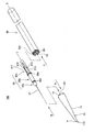
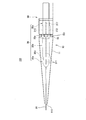
図1から図7は、本発明の一実施形態のダイレータを説明するための図である。図示したダイレータ100は、図1に示すように、拡径部10、針支持体30及び軸体50によって構成されている。
拡径部10には、針支持体30が把持する穿刺針31が挿入される挿入孔110が設けられている。そして拡径部10は、当該挿入孔110の先端の開口端pから遠ざかるにしたがって径が大きくなる拡径部位11と、後述する凹溝15とを有している。
軸体50には、拡径部10が取り付けられる。軸体50は、挿入孔110の長手方向に沿って長い形状を有している。そして、拡径部10と軸体50との境界部分は、軸体50の軸心Xを法線とする面531(図6:以降「仮想平面」と記す)を横切る線分を少なくとも1つ含む境界線555(図7)を有している。
なお、本実施形態では、拡径部10と軸体50とが接触する接触面551が仮想平面531に平行である。このような構成によれば、拡径部10と軸体50とが軸心Xに垂直な面で互いに接触することになる。
針支持体30は、拡径部10と、軸体50との間に位置し、拡径部10と軸体50とを接続している。図1中に、拡径部10に対する針支持体30の挿入方向を矢線Aで示した。この方向を以降「方向A」と記す。また、針支持体30の穿刺針31の側から反対の端部に向かう方向を矢線Bで示した。以降「方向B」と記す。さらに、針支持体30の軸体50への挿入方向を矢線Cで示した。この方向を以降「方向C」と記す。
図1から図7は、本発明の一実施形態のダイレータを説明するための図である。図示したダイレータ100は、図1に示すように、拡径部10、針支持体30及び軸体50によって構成されている。
拡径部10には、針支持体30が把持する穿刺針31が挿入される挿入孔110が設けられている。そして拡径部10は、当該挿入孔110の先端の開口端pから遠ざかるにしたがって径が大きくなる拡径部位11と、後述する凹溝15とを有している。
軸体50には、拡径部10が取り付けられる。軸体50は、挿入孔110の長手方向に沿って長い形状を有している。そして、拡径部10と軸体50との境界部分は、軸体50の軸心Xを法線とする面531(図6:以降「仮想平面」と記す)を横切る線分を少なくとも1つ含む境界線555(図7)を有している。
なお、本実施形態では、拡径部10と軸体50とが接触する接触面551が仮想平面531に平行である。このような構成によれば、拡径部10と軸体50とが軸心Xに垂直な面で互いに接触することになる。
針支持体30は、拡径部10と、軸体50との間に位置し、拡径部10と軸体50とを接続している。図1中に、拡径部10に対する針支持体30の挿入方向を矢線Aで示した。この方向を以降「方向A」と記す。また、針支持体30の穿刺針31の側から反対の端部に向かう方向を矢線Bで示した。以降「方向B」と記す。さらに、針支持体30の軸体50への挿入方向を矢線Cで示した。この方向を以降「方向C」と記す。
拡径部位11は挿入孔の開口端から遠ざかるにしたがって径が大きくなるが、拡径部10の表面に段差が生じないように拡径部10の外径がなだらかに変化することが好ましい。ただし、拡径部10の挿入に支障が無い限り所定の長さずつ、外径が変化して拡径部10に段差が生じるものであってもよい。
軸体50は、全体が挿入孔110の長手に長い形状を有するものであれば、その表面に凹凸や溝等を有するものであってもよい。拡径部10と軸体50との境界部分とは、拡径部10と軸体50とが接する部分の境界をいう。「境界線」とは、ダイレータ100の外観において、この境界が認識される線を指す。
「軸心Xを法線とする拡径部10と軸体との接触面551」は、拡径部10と軸体50とが接触する面であれば、その形状は問わない。本実施形態の接触面551は、図4に示すように、周囲が欠損した略環状の接触面551aと、略環状の面の欠損部分に相当する接触面551bとを含む。本実施形態の接触面551は接触面551a及び接触面551bの両方が仮想平面531に平行である。ただし、本実施形態はこのような構成に限定されず、主な接触面(接触面積がより大きい)接触面551aが仮想平面531に平行であればよい。
軸体50は、全体が挿入孔110の長手に長い形状を有するものであれば、その表面に凹凸や溝等を有するものであってもよい。拡径部10と軸体50との境界部分とは、拡径部10と軸体50とが接する部分の境界をいう。「境界線」とは、ダイレータ100の外観において、この境界が認識される線を指す。
「軸心Xを法線とする拡径部10と軸体との接触面551」は、拡径部10と軸体50とが接触する面であれば、その形状は問わない。本実施形態の接触面551は、図4に示すように、周囲が欠損した略環状の接触面551aと、略環状の面の欠損部分に相当する接触面551bとを含む。本実施形態の接触面551は接触面551a及び接触面551bの両方が仮想平面531に平行である。ただし、本実施形態はこのような構成に限定されず、主な接触面(接触面積がより大きい)接触面551aが仮想平面531に平行であればよい。
拡径部10には、開口端pと反対方向の端部(方向Aから見た場合の前端部)に凹溝15が形成されている。軸体50の拡径部10に向かう側の端部には凸溝55が形成されていて、凹溝15には凸溝55が針支持体30を介して嵌め込まれる。このとき、凹溝15と凸溝55とが接する境界線には、仮想平面531を横切る線分を少なくとも1つ含まれる。
また、本実施形態の針支持体30は、先端部30a、中部30b及び後部30cを有し、穿刺針31は先端部30aの先端に支持されている。針支持体30では、先端部30a及び中部30bが拡径部と連結する拡径部連結部として機能する。また、後部30cが、軸体50と連結する軸体連結部として機能する。針支持体30は、拡径部10及び軸体50と連結することによって拡径部10と軸体50とを接続する接続部として機能する。
先端部30a、中部30b及び後部30cの間にはそれぞれくびれ部30d、30eが形成されている。また、後部30cには突没自在な連結爪316と、軸心Xに沿って長い凸条部312、313、317が形成されている。
連結爪316は、爪部分316aと溝部分316bとを有している(図3)。突没自在とは、爪部分316aに圧力が加わることによって溝部分316bの中に没して爪部分316aの突出の程度が小さくなり、圧力が加わらなくなったことによって爪部分316aが溝部分316bから出て針支持体30の表面から突出することをいう。
先端部30a、中部30b及び後部30cの間にはそれぞれくびれ部30d、30eが形成されている。また、後部30cには突没自在な連結爪316と、軸心Xに沿って長い凸条部312、313、317が形成されている。
連結爪316は、爪部分316aと溝部分316bとを有している(図3)。突没自在とは、爪部分316aに圧力が加わることによって溝部分316bの中に没して爪部分316aの突出の程度が小さくなり、圧力が加わらなくなったことによって爪部分316aが溝部分316bから出て針支持体30の表面から突出することをいう。
針支持体30の一部は、拡径部10に挿入される。この時、先端部30aと中部30bとの間のくびれ部30dが拡径部10の内面と係り合う(または係合する)。なお、この点については、以下に詳細に説明する。また、針支持体30の一部は軸体50に挿入され、捩じ込まれることによって凸条部312、313、317が軸体50内壁に形成されている斜め溝560(図4)と係り合って固定される。さらに、連結爪316の爪部分316aが軸体50の内部で押圧されることによって軸体50の内壁面との間で摩擦力を生じ、針支持体30が軸体50に係止される。このとき、爪部分316aは没することによって加わった圧力を適正に逃がし、連結爪316が軸体50内で生じる摩擦力を調整する。このような構成は、針支持体30と軸体50とを適度な弾性を有する樹脂等の部材で製造することによって実現できる。
以下、上記した各構成について順により詳細に説明する。
以下、上記した各構成について順により詳細に説明する。
(拡径部)
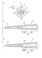
図2(a)、図2(b)及び図2(c)は、図1に示した拡径部10を詳細に説明するための図である。図2(a)は拡径部10を図1に示した矢線Aの方向から見た図である。図2(b)は、拡径部10の図2(a)に示した矢線D-Dに沿う断面図である。図2(c)は、拡径部10の図2(a)に示した矢線E-Eに沿う断面図である。図2(b)、図2(c)に示すように、拡径部10の軸心は、軸体50の軸心Xに一致している。
図2(a)から図2(c)に示したように、拡径部10の拡径部位11の内径の一部は、外径と同様に、方向Aの反対方向に向かって大きくなっている。拡径部位11の内壁には位置合わせ凸部111が形成されていて、位置合わせ凸部111は、拡径部10と針支持体30との位置合わせに利用される。
拡径部10の開口端pが形成されている端部の他方の端部には、凹溝15が形成されている。凹溝15は軸体50の凸溝55と嵌合する際に、接触面551a(図4)と接触する略環状の接触面151a、接触面551bと接触する接触面151bを有している(図2)。接触面151a及び接触面151bは、本実施形態の拡径部10が軸体50と接触する拡径部10側の接触面151となる。
図2(a)、図2(b)及び図2(c)は、図1に示した拡径部10を詳細に説明するための図である。図2(a)は拡径部10を図1に示した矢線Aの方向から見た図である。図2(b)は、拡径部10の図2(a)に示した矢線D-Dに沿う断面図である。図2(c)は、拡径部10の図2(a)に示した矢線E-Eに沿う断面図である。図2(b)、図2(c)に示すように、拡径部10の軸心は、軸体50の軸心Xに一致している。
図2(a)から図2(c)に示したように、拡径部10の拡径部位11の内径の一部は、外径と同様に、方向Aの反対方向に向かって大きくなっている。拡径部位11の内壁には位置合わせ凸部111が形成されていて、位置合わせ凸部111は、拡径部10と針支持体30との位置合わせに利用される。
拡径部10の開口端pが形成されている端部の他方の端部には、凹溝15が形成されている。凹溝15は軸体50の凸溝55と嵌合する際に、接触面551a(図4)と接触する略環状の接触面151a、接触面551bと接触する接触面151bを有している(図2)。接触面151a及び接触面151bは、本実施形態の拡径部10が軸体50と接触する拡径部10側の接触面151となる。
図2(b)、図2(c)に示すように、拡径部10はその内部に、挿入孔110と空洞部120とを有し、空洞部120は前空洞部120aと後空洞部120bとを有している。前空洞部120aは針支持体30の先端部30aと嵌合し、後空洞部120bには中部30bが嵌合される。また、前空洞部120aを形成する拡径部10の内壁と後空洞部120bを形成する内壁との間にはくびれ部120dが形成されていて、くびれ部120dには針支持体30のくびれ部30dが嵌合される。
(針支持体)
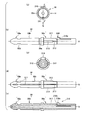
図3(a)から図3(e)は、図1に示した針支持体30を説明するための図である。図3(a)は、針支持体30を図1に示した矢線Bの方向から見た正面図である。図3(b)は、針支持体30を図3(a)中の矢線Hの方向から見た側面図である。図3(c)は、針支持体30を図1に示した矢線Bの反対の方向から見た背面図である。図3(d)は、針支持体30を図3(a)中の矢線Gの方向から見た側面図である。図3(e)は、図3(a)中の矢線F-Fに沿う針支持体30の断面図である。針支持体30の軸心は、軸体50の軸心Xに一致している。
図1において説明したように、針支持体30は、先端部30a、中部30b及び後部30cを有している。先端部30aと中部30bとの間にはくびれ部30dが、中部30bと後部30cとの間にはくびれ部30eがそれぞれ形成されている。また、後部30cには凸条部312、313、317及び連結爪316が形成されている。
図3(a)から図3(e)は、図1に示した針支持体30を説明するための図である。図3(a)は、針支持体30を図1に示した矢線Bの方向から見た正面図である。図3(b)は、針支持体30を図3(a)中の矢線Hの方向から見た側面図である。図3(c)は、針支持体30を図1に示した矢線Bの反対の方向から見た背面図である。図3(d)は、針支持体30を図3(a)中の矢線Gの方向から見た側面図である。図3(e)は、図3(a)中の矢線F-Fに沿う針支持体30の断面図である。針支持体30の軸心は、軸体50の軸心Xに一致している。
図1において説明したように、針支持体30は、先端部30a、中部30b及び後部30cを有している。先端部30aと中部30bとの間にはくびれ部30dが、中部30bと後部30cとの間にはくびれ部30eがそれぞれ形成されている。また、後部30cには凸条部312、313、317及び連結爪316が形成されている。
先端部30a及び中部30bは、拡径部10に対する針支持体30の角度を定める拡径部側位置合わせ部である位置合わせ凹部311を備えている。前記した拡径部10に設けられた位置合わせ凸部111は、拡径部側位置合わせ部として機能する。具体的には、位置合わせ凹部311は、図3(a)、(d)に示すように、針支持体30の側面に設けられ、拡径部10内面に形成されている位置合わせ凸部111と嵌合することによって空洞部120内に固定される針支持体30の角度を決定している。なお、ここでいう角度とは、針支持体30の拡径部10に対する捻り方向の向きを指している。
(軸体)
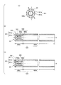
図4(a)、図4(b)及び図4(c)は、図1に示した軸体50を説明するための図である。図4(a)は、図1に示した方向Cから軸体50を見た図である。図4(b)は、軸体50の図4(a)に示した矢線I-Iに沿う断面図である。図4(c)は、軸体50の図4(a)に示した矢線J-Jに沿う断面図である。軸体50は、内部に空洞部520を有し、空洞部520は前部520aと後部520bとを含んでいる。前部520aは針支持体30の凸条部312、313、317と嵌合する斜め溝560を有し、後部520bは前部520aよりも広い一定の径を有している。
軸体50においては、拡径部10に相対する凸溝55の接触面551bと、凸溝55の基端となる接触面551aとが拡径部10と接触する接触面551を形成する。本実施形態では、前記したように、接触面551a及び接触面551bのいずれもが仮想平面531と平行になっている。
図4(a)、図4(b)及び図4(c)は、図1に示した軸体50を説明するための図である。図4(a)は、図1に示した方向Cから軸体50を見た図である。図4(b)は、軸体50の図4(a)に示した矢線I-Iに沿う断面図である。図4(c)は、軸体50の図4(a)に示した矢線J-Jに沿う断面図である。軸体50は、内部に空洞部520を有し、空洞部520は前部520aと後部520bとを含んでいる。前部520aは針支持体30の凸条部312、313、317と嵌合する斜め溝560を有し、後部520bは前部520aよりも広い一定の径を有している。
軸体50においては、拡径部10に相対する凸溝55の接触面551bと、凸溝55の基端となる接触面551aとが拡径部10と接触する接触面551を形成する。本実施形態では、前記したように、接触面551a及び接触面551bのいずれもが仮想平面531と平行になっている。
前部520aの内面には、斜め溝560が設けられている。この斜め溝560は、凹面560a及び凸条部560bによって形成されている。長手方向における凹面560aの底面は、軸心Xと平行に位置する。さらに軸体50の前部520aであって、針支持体30が挿入される側の端部には、軸心に対して斜めに形成された斜面561を有している。凹面560aは、斜面561に続く凹面である。
(係り合い(係合)
図5は、図2から図4に示した拡径部10、針支持体30及び軸体50を組み合わせた状態を示した図である。本実施形態では、先ず、針支持体30の先端部30a及び中部30bが拡径部10に挿入される。このとき、ダイレータを使用する術者は、穿刺針31及び針支持体30を拡径部10の空洞部120内に挿入し、回転させることによって拡径部10に設けられた位置合わせ凸部111に針支持体30の側面に設けられた位置合わせ凹部311を嵌合させる。このような動作により、空洞部120内における針支持体30の角度が決定する。また、針支持体30のくびれ部30dは拡径部10の内壁に設けられたくびれ部120d(図2)に対して着脱可能に嵌り、くびれ部30eは後空洞部120bの後端に係り合う。
また、本実施形態では、針支持体30の後部30cを軸体50に捻じ込むように挿入すると、凸条部312、313、317が斜面561に導かれて凹面560aに入り込む。凸条部312は、図3(c)に示したように、軸心Xに垂直な断面が略半円の形状を有している。図4(a)に示すように凹面560aは軸心Xに垂直な断面が円弧形状の曲面である。このため、凸条部312は斜面561に沿って凹面560a内にスムーズに入り込み、凹面560aと嵌合する。
連結爪316は、針支持体30が軸体50に捻じ込まれる際には爪部分316aが溝316bに没した状態で前部520a内に挿入される。そして、凸条部312が斜め溝560と嵌合される状態においては、連結爪316が形成された部分は、後部520bに挿入されている。後部520bは前部520aよりも径が大きいため、連結爪316の爪部分316aは溝から出て凸状態になり、前部520aと後部520bとの間に生じる段差部に掛止される。これにより、針支持体30が軸体50に対して脱離不可となる。
図5は、図2から図4に示した拡径部10、針支持体30及び軸体50を組み合わせた状態を示した図である。本実施形態では、先ず、針支持体30の先端部30a及び中部30bが拡径部10に挿入される。このとき、ダイレータを使用する術者は、穿刺針31及び針支持体30を拡径部10の空洞部120内に挿入し、回転させることによって拡径部10に設けられた位置合わせ凸部111に針支持体30の側面に設けられた位置合わせ凹部311を嵌合させる。このような動作により、空洞部120内における針支持体30の角度が決定する。また、針支持体30のくびれ部30dは拡径部10の内壁に設けられたくびれ部120d(図2)に対して着脱可能に嵌り、くびれ部30eは後空洞部120bの後端に係り合う。
また、本実施形態では、針支持体30の後部30cを軸体50に捻じ込むように挿入すると、凸条部312、313、317が斜面561に導かれて凹面560aに入り込む。凸条部312は、図3(c)に示したように、軸心Xに垂直な断面が略半円の形状を有している。図4(a)に示すように凹面560aは軸心Xに垂直な断面が円弧形状の曲面である。このため、凸条部312は斜面561に沿って凹面560a内にスムーズに入り込み、凹面560aと嵌合する。
連結爪316は、針支持体30が軸体50に捻じ込まれる際には爪部分316aが溝316bに没した状態で前部520a内に挿入される。そして、凸条部312が斜め溝560と嵌合される状態においては、連結爪316が形成された部分は、後部520bに挿入されている。後部520bは前部520aよりも径が大きいため、連結爪316の爪部分316aは溝から出て凸状態になり、前部520aと後部520bとの間に生じる段差部に掛止される。これにより、針支持体30が軸体50に対して脱離不可となる。
(境界線)
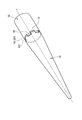
図6は、本実施形態の拡径部10と軸体50との境界について説明するための図である。図示するように、拡径部10と軸体50とは、凹溝15と凸溝55とによって接している。拡径部10の側の接触面151と軸体50の側の接触面551との境界を、本実施形態では「拡径部10と軸体50との境界」とする。凸溝55は、凹溝15に重ねられて拡径部10と軸体50とが相対的に回転することを防いでいる。このため、本実施形態は、例えば螺合等することによって拡径部10と軸体50とを直接接続することができず、接続部としての針支持体30を介して両者を接続している。
図6は、本実施形態の拡径部10と軸体50との境界について説明するための図である。図示するように、拡径部10と軸体50とは、凹溝15と凸溝55とによって接している。拡径部10の側の接触面151と軸体50の側の接触面551との境界を、本実施形態では「拡径部10と軸体50との境界」とする。凸溝55は、凹溝15に重ねられて拡径部10と軸体50とが相対的に回転することを防いでいる。このため、本実施形態は、例えば螺合等することによって拡径部10と軸体50とを直接接続することができず、接続部としての針支持体30を介して両者を接続している。
図7(a)、図7(b)及び図7(c)は、拡径部10と軸体50との境界を示す境界線を例示する模式図である。境界線は、凹溝15と凸溝55との境界を示す線であり、凹溝15の外縁を示す線または凸溝55の外縁を示す線と一致している。図7(a)では、凸溝55の外縁を示す線を境界線555として示す。
図7(a)に示したように、境界線555は、仮想平面531を垂直に横切る線分555aと、仮想平面531に平行な線分555bとを含んでいる。このような境界線555は、仮想平面531を垂直に複数回横切るものになる。
上記境界線555は、全体に複数のパルス波を描くような形状を有している。本実施形態では、例えば、このようなパルス波を5個以上、より好ましくは6個以上、8個以下配置するものとした。このため本実施形態では、接触面551が略円環形状であり、境界線555は接触面551の外周を6周期から8周期で一周する波形を含む形状となっている。ここで、波形の形状は特に限定されず、本実施形態のように矩形波(パルス波)でもよく、三角波や正弦波でもよい。本実施形態では、パルス波のデューティ比を例えば50%とすることができる。
このように、境界線555が仮想平面531を垂直に横切る線分555aを含むようにすると、軸体50から拡径部10の側に作用する力の方向が垂直になる。このため、術者がダイレータ100を押入しようと軸体50に力を加えたとき、ダイレータ100に不測の横方向の力が働き難くなって術者によるダイレータの操作精度を高めることができる。
図7(a)に示したように、境界線555は、仮想平面531を垂直に横切る線分555aと、仮想平面531に平行な線分555bとを含んでいる。このような境界線555は、仮想平面531を垂直に複数回横切るものになる。
上記境界線555は、全体に複数のパルス波を描くような形状を有している。本実施形態では、例えば、このようなパルス波を5個以上、より好ましくは6個以上、8個以下配置するものとした。このため本実施形態では、接触面551が略円環形状であり、境界線555は接触面551の外周を6周期から8周期で一周する波形を含む形状となっている。ここで、波形の形状は特に限定されず、本実施形態のように矩形波(パルス波)でもよく、三角波や正弦波でもよい。本実施形態では、パルス波のデューティ比を例えば50%とすることができる。
このように、境界線555が仮想平面531を垂直に横切る線分555aを含むようにすると、軸体50から拡径部10の側に作用する力の方向が垂直になる。このため、術者がダイレータ100を押入しようと軸体50に力を加えたとき、ダイレータ100に不測の横方向の力が働き難くなって術者によるダイレータの操作精度を高めることができる。
図7(b)は、本実施形態の境界線の他の例を示している。図7(b)に示した境界線575は、仮想平面531を斜めに複数回横切る線となる。また、境界線575は、仮想平面531を斜めに横切る線分575aと、仮想平面531に平行な線分575bとを含んでいる。このような境界線575は、全体に複数の鋸波を含むような形状を有している。境界線575が、6個から8個の鋸波を含む場合、境界線575は、接触面551の外周を6周期から8周期で一周する波形を含むものになる。
また、図7(b)に示した境界線575は、図7(a)に示した境界線555よりも仮想平面531に平行な線分を含む箇所が少なくなっている。このため、境界線575は、境界線555よりも皮膚や組織を挟み込み可能性が低いものといえる。
また、図7(c)は、本実施形態のさらに境界線の他の例を示している。図7(c)に示した構成では、軸体の軸心に垂直な拡径部と軸体との接触面がなく、両者は複数のカーブを有する曲面で接触している。このような例では、境界線595は軸心に垂直な仮想平面531を斜めに複数回横切る曲線を描くものとなる。
また、図7(b)に示した境界線575は、図7(a)に示した境界線555よりも仮想平面531に平行な線分を含む箇所が少なくなっている。このため、境界線575は、境界線555よりも皮膚や組織を挟み込み可能性が低いものといえる。
また、図7(c)は、本実施形態のさらに境界線の他の例を示している。図7(c)に示した構成では、軸体の軸心に垂直な拡径部と軸体との接触面がなく、両者は複数のカーブを有する曲面で接触している。このような例では、境界線595は軸心に垂直な仮想平面531を斜めに複数回横切る曲線を描くものとなる。
(動作)
次に、本実施形態のダイレータ100を術者が使用する際の動作を説明する。術者は、先ず、被験者の体壁に形成された穿刺孔に拡径部10及び拡径部10に嵌合された針支持体30を押入する。そして、穿刺孔が所定の径まで拡張すると、術者は針支持体30に軸体50を取りつけて更にダイレータ100を押入する。ダイレータ100を穿刺孔に押入する時、軸体50には力が加わるが、連結爪316や凸条部312を軸体50の内部に捻じ込んであるため、軸体50は外れることがない。このとき、ダイレータ100に図示しないシースを被せることにより、ダイレータ100の押入がいっそうスムーズになる。
このような動作において、本実施形態のダイレータは、図7(a)、(b)に示したように、軸心の周方向に沿う境界線の連続性が境界線を横切る線分によって絶たれている。このため、周方向の境界線に皮膚や組織が入り込み難くなる。このような本実施形態では、拡径部10と軸体50との間に皮膚等が入り込む可能性が低いので、シースを使用しなくても、あるいは被せたシースがずれて拡径部10と軸体50との境界が外部に露出した場合であっても、ダイレータ100をスムーズに動かすことができる。このような本実施形態は、ダイレータの体壁への押入時に拡径部と胴体部との境界の影響がより少ないダイレータを提供することができるものといえる。
次に、本実施形態のダイレータ100を術者が使用する際の動作を説明する。術者は、先ず、被験者の体壁に形成された穿刺孔に拡径部10及び拡径部10に嵌合された針支持体30を押入する。そして、穿刺孔が所定の径まで拡張すると、術者は針支持体30に軸体50を取りつけて更にダイレータ100を押入する。ダイレータ100を穿刺孔に押入する時、軸体50には力が加わるが、連結爪316や凸条部312を軸体50の内部に捻じ込んであるため、軸体50は外れることがない。このとき、ダイレータ100に図示しないシースを被せることにより、ダイレータ100の押入がいっそうスムーズになる。
このような動作において、本実施形態のダイレータは、図7(a)、(b)に示したように、軸心の周方向に沿う境界線の連続性が境界線を横切る線分によって絶たれている。このため、周方向の境界線に皮膚や組織が入り込み難くなる。このような本実施形態では、拡径部10と軸体50との間に皮膚等が入り込む可能性が低いので、シースを使用しなくても、あるいは被せたシースがずれて拡径部10と軸体50との境界が外部に露出した場合であっても、ダイレータ100をスムーズに動かすことができる。このような本実施形態は、ダイレータの体壁への押入時に拡径部と胴体部との境界の影響がより少ないダイレータを提供することができるものといえる。
なお、本発明のダイレータは、当然のことながら、上記実施形態に限定されるものではない。例えば、境界線は上記パルス波、鋸波及びカーブの形状を有するものに限定されるものでなく、軸体の軸心に垂直な面を横切る線分を含むものであればどのような形状であってもよい。特に、境界線をパルスや鋸波を含む形状にする場合、パルス等の間隔やパルス等の高さは、使用の対象となる皮膚や組織の弾力や厚さに応じて適宜選択される。
また、本発明のダイレータは、境界線がパルス波等の形状を有する部位をダイレータの周囲に6個以上設ける構成に限定されず、任意の数のパルス波等を設定することができる。パルス波等の数や形状は、主に被験者の皮膚や組織の弾性や柔軟性、さらには厚さ等によって適正に選択される。
また、本発明のダイレータは、境界線がパルス波等の形状を有する部位をダイレータの周囲に6個以上設ける構成に限定されず、任意の数のパルス波等を設定することができる。パルス波等の数や形状は、主に被験者の皮膚や組織の弾性や柔軟性、さらには厚さ等によって適正に選択される。
本発明のダイレータによれば、拡径部と胴体部との境界による体壁への押入時の影響をより少なくすることができる。
10・・・拡径部
11・・・拡径部位
15・・・凹溝
30・・・針支持体
30a・・・先端部
30b・・・中部
30c・・・後部
30d、30e、120d・・・くびれ部
31・・・穿刺針
50・・・軸体
55・・・凸溝
100・・・ダイレータ
110・・・挿入孔
111・・・位置合わせ凸部
120・・・空洞部
120a・・・前空洞部
120b・・・後空洞部
151,151a,151b,551,551a,551b・・・接触面
311・・・位置合わせ凹部
312,313,317・・・凸条部
316・・・連結爪
316a・・・爪部分
316b・・・溝部分
520・・・空洞部
520a・・・前部
520b・・・後部
531・・・仮想平面
555,575,595・・・境界線
555a,555b,575a,575b・・・線分
560・・・斜め溝
560a・・・凹面
560b・・・凸条部
561・・・斜面
p・・・開口端
11・・・拡径部位
15・・・凹溝
30・・・針支持体
30a・・・先端部
30b・・・中部
30c・・・後部
30d、30e、120d・・・くびれ部
31・・・穿刺針
50・・・軸体
55・・・凸溝
100・・・ダイレータ
110・・・挿入孔
111・・・位置合わせ凸部
120・・・空洞部
120a・・・前空洞部
120b・・・後空洞部
151,151a,151b,551,551a,551b・・・接触面
311・・・位置合わせ凹部
312,313,317・・・凸条部
316・・・連結爪
316a・・・爪部分
316b・・・溝部分
520・・・空洞部
520a・・・前部
520b・・・後部
531・・・仮想平面
555,575,595・・・境界線
555a,555b,575a,575b・・・線分
560・・・斜め溝
560a・・・凹面
560b・・・凸条部
561・・・斜面
p・・・開口端
Claims (10)
- 穿刺針が挿入される挿入孔を有し、前記挿入孔の先端開口部から遠ざかるにしたがって径が大きくなる拡径部位を有する拡径部と、
前記拡径部が取り付けられて、前記挿入孔の長手方向に沿って長い軸体とを備えたダイレータであって、
前記拡径部と前記軸体との境界部分は、前記軸体の軸心を法線とする仮想平面を横切る線分を少なくとも1つ含む境界線を有することを特徴とするダイレータ。 - 前記拡径部と前記軸体とが接触する接触面は、前記仮想平面に平行である、請求項1に記載のダイレータ。
- 前記境界線は、前記仮想平面を垂直に複数回横切る、請求項1または2に記載のダイレータ。
- 前記境界線は、前記仮想平面を斜めに複数回横切る、請求項1または2に記載のダイレータ。
- 前記拡径部と、前記軸体とを接続する接続部をさらに有し、この接続部が前記拡径部と連結する拡径部連結部と、前記軸体と連結する軸体連結部とを有する請求項1から4のいずれか1項に記載のダイレータ。
- 前記接続部は、先端が穿刺針を保持する針支持体である、請求項5に記載のダイレータ。
- 前記軸体は、その側面に、前記軸心と平行な凸条部を有し、さらに前記軸体連結部が挿入される側の端部に、斜め溝を有し、
前記斜め溝は、前記軸心に対して斜めに形成された斜面と、当該斜面に続く凹面とを有する、請求項5または6に記載のダイレータ。 - 前記接続部の前記軸体連結部は、前記軸体に挿入される突没自在な連結爪を備える、請求項5から7のいずれか1項に記載のダイレータ。
- 前記拡径部は、前記拡径部に対する前記接続部の角度を定める拡径部側位置合わせ部を備え、
前記拡径部連結部は、前記拡径部側位置合わせ部と係り合う接続部側位置合わせ部を備える、請求項5から8のいずれか1項に記載のダイレータ。 - 前記接触面が略円環形状であって、
前記境界線は前記接触面の外周を6周期から8周期で一周する波形を含む、請求項2に記載のダイレータ。
Priority Applications (2)
| Application Number | Priority Date | Filing Date | Title |
|---|---|---|---|
| CN201780040377.1A CN109414279A (zh) | 2016-08-31 | 2017-08-30 | 扩张器 |
| KR1020187036942A KR20190005232A (ko) | 2016-08-31 | 2017-08-30 | 다이레이터 |
Applications Claiming Priority (2)
| Application Number | Priority Date | Filing Date | Title |
|---|---|---|---|
| JP2016170111A JP6399061B2 (ja) | 2016-08-31 | 2016-08-31 | ダイレータ |
| JP2016-170111 | 2016-08-31 |
Publications (1)
| Publication Number | Publication Date |
|---|---|
| WO2018043544A1 true WO2018043544A1 (ja) | 2018-03-08 |
Family
ID=61301165
Family Applications (1)
| Application Number | Title | Priority Date | Filing Date |
|---|---|---|---|
| PCT/JP2017/031113 Ceased WO2018043544A1 (ja) | 2016-08-31 | 2017-08-30 | ダイレータ |
Country Status (4)
| Country | Link |
|---|---|
| JP (1) | JP6399061B2 (ja) |
| KR (1) | KR20190005232A (ja) |
| CN (1) | CN109414279A (ja) |
| WO (1) | WO2018043544A1 (ja) |
Citations (3)
| Publication number | Priority date | Publication date | Assignee | Title |
|---|---|---|---|---|
| JPH0951953A (ja) * | 1995-08-11 | 1997-02-25 | Terumo Corp | ダイレーターおよびイントロデューサー |
| WO2013065292A1 (ja) * | 2011-10-31 | 2013-05-10 | 住友ベークライト株式会社 | 医療用拡張器および医療用拡張器セット |
| JP2014004015A (ja) * | 2012-06-21 | 2014-01-16 | Olympus Corp | アクセスポート |
Family Cites Families (3)
| Publication number | Priority date | Publication date | Assignee | Title |
|---|---|---|---|---|
| EP2198781B1 (en) * | 2007-10-02 | 2012-05-23 | Terumo Kabushiki Kaisha | Puncture set |
| EP2740512B1 (en) * | 2011-08-01 | 2016-10-12 | Terumo Kabushiki Kaisha | Dilator, introducer assembly, and medical tool |
| KR101793801B1 (ko) * | 2013-02-22 | 2017-11-03 | 스미또모 베이크라이트 가부시키가이샤 | 연발식 장기 고정구 |
-
2016
- 2016-08-31 JP JP2016170111A patent/JP6399061B2/ja active Active
-
2017
- 2017-08-30 KR KR1020187036942A patent/KR20190005232A/ko not_active Ceased
- 2017-08-30 CN CN201780040377.1A patent/CN109414279A/zh active Pending
- 2017-08-30 WO PCT/JP2017/031113 patent/WO2018043544A1/ja not_active Ceased
Patent Citations (3)
| Publication number | Priority date | Publication date | Assignee | Title |
|---|---|---|---|---|
| JPH0951953A (ja) * | 1995-08-11 | 1997-02-25 | Terumo Corp | ダイレーターおよびイントロデューサー |
| WO2013065292A1 (ja) * | 2011-10-31 | 2013-05-10 | 住友ベークライト株式会社 | 医療用拡張器および医療用拡張器セット |
| JP2014004015A (ja) * | 2012-06-21 | 2014-01-16 | Olympus Corp | アクセスポート |
Also Published As
| Publication number | Publication date |
|---|---|
| JP2018033728A (ja) | 2018-03-08 |
| JP6399061B2 (ja) | 2018-10-03 |
| KR20190005232A (ko) | 2019-01-15 |
| CN109414279A (zh) | 2019-03-01 |
Similar Documents
| Publication | Publication Date | Title |
|---|---|---|
| JP5145113B2 (ja) | 内視鏡用処置具の操作部 | |
| JP5435923B2 (ja) | 臓器内穿刺孔封止装置 | |
| JP6050750B2 (ja) | イントロデューサ用シース | |
| JP6072371B2 (ja) | 医療器具及び医療システム | |
| EP1882451A2 (en) | Clip apparatus for ligaturing living tissue | |
| US4957502A (en) | Surgical needle for plastic surgery or the like | |
| JP2011083606A (ja) | 回転ロック付きのカテーテルのシース導入器 | |
| JP2009523044A (ja) | 外科結紮クリップ | |
| JP2010540189A (ja) | 刺し穴を閉鎖するためのシステム及び方法 | |
| CN109009355A (zh) | 一种心包穿刺针组件 | |
| JP2008545459A (ja) | 穿刺部の位置探り出し装置 | |
| CN113116407A (zh) | 封堵装置 | |
| JP6399061B2 (ja) | ダイレータ | |
| TWI644645B (zh) | 埋線刺入器 | |
| WO2018047340A1 (ja) | 医療器具及び医療システム | |
| JP6881367B2 (ja) | ダイレータ | |
| JP6612013B2 (ja) | 拡張器センタリングデバイス及びアセンブリ | |
| JP6091723B2 (ja) | 医療器具 | |
| JP6276987B2 (ja) | トロカール | |
| JP6210839B2 (ja) | 胃壁固定器具 | |
| JP2007330548A (ja) | 診断治療用ガイドカテーテル | |
| CN113116409A (zh) | 封堵装置及封堵装置输送系统 | |
| JP2013255756A (ja) | 内視鏡用処置具 | |
| KR101514055B1 (ko) | 스텐트 삽입장치 | |
| JP2021078576A (ja) | カテーテルワイヤ固定具及びこれを用いた医療用具 |
Legal Events
| Date | Code | Title | Description |
|---|---|---|---|
| 121 | Ep: the epo has been informed by wipo that ep was designated in this application |
Ref document number: 17846548 Country of ref document: EP Kind code of ref document: A1 |
|
| ENP | Entry into the national phase |
Ref document number: 20187036942 Country of ref document: KR Kind code of ref document: A |
|
| NENP | Non-entry into the national phase |
Ref country code: DE |
|
| 122 | Ep: pct application non-entry in european phase |
Ref document number: 17846548 Country of ref document: EP Kind code of ref document: A1 |