WO2018043339A1 - 車両用の後処理システムおよび車両の後処理方法 - Google Patents
車両用の後処理システムおよび車両の後処理方法 Download PDFInfo
- Publication number
- WO2018043339A1 WO2018043339A1 PCT/JP2017/030560 JP2017030560W WO2018043339A1 WO 2018043339 A1 WO2018043339 A1 WO 2018043339A1 JP 2017030560 W JP2017030560 W JP 2017030560W WO 2018043339 A1 WO2018043339 A1 WO 2018043339A1
- Authority
- WO
- WIPO (PCT)
- Prior art keywords
- temperature
- exhaust
- opening timing
- combustion
- flow rate
- Prior art date
- Legal status (The legal status is an assumption and is not a legal conclusion. Google has not performed a legal analysis and makes no representation as to the accuracy of the status listed.)
- Ceased
Links
Images



Classifications
-
- F—MECHANICAL ENGINEERING; LIGHTING; HEATING; WEAPONS; BLASTING
- F01—MACHINES OR ENGINES IN GENERAL; ENGINE PLANTS IN GENERAL; STEAM ENGINES
- F01N—GAS-FLOW SILENCERS OR EXHAUST APPARATUS FOR MACHINES OR ENGINES IN GENERAL; GAS-FLOW SILENCERS OR EXHAUST APPARATUS FOR INTERNAL-COMBUSTION ENGINES
- F01N3/00—Exhaust or silencing apparatus having means for purifying, rendering innocuous, or otherwise treating exhaust
- F01N3/02—Exhaust or silencing apparatus having means for purifying, rendering innocuous, or otherwise treating exhaust for cooling, or for removing solid constituents of, exhaust
- F01N3/021—Exhaust or silencing apparatus having means for purifying, rendering innocuous, or otherwise treating exhaust for cooling, or for removing solid constituents of, exhaust by means of filters
- F01N3/023—Exhaust or silencing apparatus having means for purifying, rendering innocuous, or otherwise treating exhaust for cooling, or for removing solid constituents of, exhaust by means of filters using means for regenerating the filters, e.g. by burning trapped particles
-
- F—MECHANICAL ENGINEERING; LIGHTING; HEATING; WEAPONS; BLASTING
- F01—MACHINES OR ENGINES IN GENERAL; ENGINE PLANTS IN GENERAL; STEAM ENGINES
- F01N—GAS-FLOW SILENCERS OR EXHAUST APPARATUS FOR MACHINES OR ENGINES IN GENERAL; GAS-FLOW SILENCERS OR EXHAUST APPARATUS FOR INTERNAL-COMBUSTION ENGINES
- F01N3/00—Exhaust or silencing apparatus having means for purifying, rendering innocuous, or otherwise treating exhaust
- F01N3/02—Exhaust or silencing apparatus having means for purifying, rendering innocuous, or otherwise treating exhaust for cooling, or for removing solid constituents of, exhaust
- F01N3/021—Exhaust or silencing apparatus having means for purifying, rendering innocuous, or otherwise treating exhaust for cooling, or for removing solid constituents of, exhaust by means of filters
- F01N3/023—Exhaust or silencing apparatus having means for purifying, rendering innocuous, or otherwise treating exhaust for cooling, or for removing solid constituents of, exhaust by means of filters using means for regenerating the filters, e.g. by burning trapped particles
- F01N3/025—Exhaust or silencing apparatus having means for purifying, rendering innocuous, or otherwise treating exhaust for cooling, or for removing solid constituents of, exhaust by means of filters using means for regenerating the filters, e.g. by burning trapped particles using fuel burner or by adding fuel to exhaust
-
- F—MECHANICAL ENGINEERING; LIGHTING; HEATING; WEAPONS; BLASTING
- F01—MACHINES OR ENGINES IN GENERAL; ENGINE PLANTS IN GENERAL; STEAM ENGINES
- F01N—GAS-FLOW SILENCERS OR EXHAUST APPARATUS FOR MACHINES OR ENGINES IN GENERAL; GAS-FLOW SILENCERS OR EXHAUST APPARATUS FOR INTERNAL-COMBUSTION ENGINES
- F01N3/00—Exhaust or silencing apparatus having means for purifying, rendering innocuous, or otherwise treating exhaust
- F01N3/02—Exhaust or silencing apparatus having means for purifying, rendering innocuous, or otherwise treating exhaust for cooling, or for removing solid constituents of, exhaust
- F01N3/021—Exhaust or silencing apparatus having means for purifying, rendering innocuous, or otherwise treating exhaust for cooling, or for removing solid constituents of, exhaust by means of filters
- F01N3/033—Exhaust or silencing apparatus having means for purifying, rendering innocuous, or otherwise treating exhaust for cooling, or for removing solid constituents of, exhaust by means of filters in combination with other devices
-
- F—MECHANICAL ENGINEERING; LIGHTING; HEATING; WEAPONS; BLASTING
- F02—COMBUSTION ENGINES; HOT-GAS OR COMBUSTION-PRODUCT ENGINE PLANTS
- F02D—CONTROLLING COMBUSTION ENGINES
- F02D13/00—Controlling the engine output power by varying inlet or exhaust valve operating characteristics, e.g. timing
- F02D13/02—Controlling the engine output power by varying inlet or exhaust valve operating characteristics, e.g. timing during engine operation
-
- Y—GENERAL TAGGING OF NEW TECHNOLOGICAL DEVELOPMENTS; GENERAL TAGGING OF CROSS-SECTIONAL TECHNOLOGIES SPANNING OVER SEVERAL SECTIONS OF THE IPC; TECHNICAL SUBJECTS COVERED BY FORMER USPC CROSS-REFERENCE ART COLLECTIONS [XRACs] AND DIGESTS
- Y02—TECHNOLOGIES OR APPLICATIONS FOR MITIGATION OR ADAPTATION AGAINST CLIMATE CHANGE
- Y02T—CLIMATE CHANGE MITIGATION TECHNOLOGIES RELATED TO TRANSPORTATION
- Y02T10/00—Road transport of goods or passengers
- Y02T10/10—Internal combustion engine [ICE] based vehicles
- Y02T10/12—Improving ICE efficiencies
Definitions
- the present disclosure relates to a vehicle post-processing system and a vehicle post-processing method.
- Exhaust gas generated in the internal combustion engine of the vehicle is processed by a post-processing device provided in the middle of the exhaust flow path before being discharged from the vehicle into the atmosphere.
- DPF Diesel Particulate Filter
- urea SCR Selective Catalytic Reduction
- the DPF (hereinafter referred to as a filter) collects particulate matter (hereinafter referred to as PM) contained in the exhaust gas.
- PM particulate matter
- the amount of PM accumulated on the filter is estimated based on the operating state of the internal combustion engine, and when the estimated amount of PM accumulated reaches a predetermined amount, post-injection for injecting fuel into the cylinder after combustion or exhaust flow is performed.
- a technique has been proposed in which the PM accumulated on the filter is burned and removed (so-called forced regeneration) with the heat obtained by injecting the fuel into the road and injecting the fuel into the exhaust pipe. (For example, refer to Patent Document 1).
- An object of the present disclosure is to provide a vehicle post-processing system and a vehicle post-processing method capable of realizing fuel consumption reduction.
- a vehicle post-processing system includes: A filter that is provided in an exhaust system that leads to an exhaust valve that opens and closes an exhaust port provided in the cylinder, and that collects particulate matter in the exhaust discharged from the exhaust port; A variable valve mechanism for adjusting the opening timing of the exhaust valve between a maximum advance opening timing and a maximum retard opening timing; A temperature detector for detecting an exhaust temperature in the exhaust system; A first temperature calculation unit that calculates a first temperature as an exhaust temperature when the opening timing of the exhaust valve is adjusted to a maximum advance opening timing; When the detected exhaust temperature is lower than the combustion temperature of the particulate matter, it is determined whether the first temperature is equal to or higher than the combustion temperature, and the first temperature is equal to or higher than the combustion temperature. A control unit that controls the variable valve mechanism to adjust the opening timing of the exhaust valve to the maximum advance opening timing; Is provided.
- the vehicle post-processing method includes: A filter that collects particulate matter in the exhaust discharged from the exhaust port is provided in an exhaust system that communicates with an exhaust valve that opens and closes an exhaust port provided in the cylinder.
- a vehicle post-processing method provided with a variable valve mechanism that adjusts between a timing and a maximum retard opening timing, Detecting the exhaust temperature in the exhaust system; Calculating a first temperature as an exhaust temperature when the opening timing of the exhaust valve is adjusted to a maximum advance opening timing; If the detected exhaust temperature is less than the combustion temperature of the particulate matter, determine whether the first temperature is greater than or equal to the combustion temperature; When the first temperature is equal to or higher than the combustion temperature, the variable valve mechanism is controlled to adjust the opening timing of the exhaust valve to the maximum advance opening timing.
- FIG. 1 is a diagram illustrating an overall configuration of a vehicle post-processing system according to an embodiment of the present disclosure.
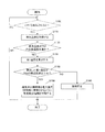
- FIG. 2 is a flowchart showing the operation of the post-processing system.
- FIG. 3 is a diagram illustrating a partial configuration of the post-processing system according to the modified example of the embodiment of the present disclosure.
- FIG. 4 is a flowchart showing the operation of the post-processing system in the modified example.
- FIG. 1 is a diagram illustrating an overall configuration of a vehicle post-processing system 1 according to an embodiment of the present disclosure.
- an aftertreatment system 1 is mounted on a vehicle, and is an internal combustion engine 100, an exhaust system 200, an intake system 300, and an engine control unit (hereinafter referred to as an ECU) 400 (a control object of the present disclosure). Corresponding to “part”).
- the internal combustion engine 100 is, for example, a four-stroke cycle diesel engine having an intake stroke, a compression stroke, an expansion stroke (combustion stroke), and an exhaust stroke, and includes a combustion chamber 102, an injector 104, an intake valve 106, and an exhaust gas.
- a valve 108 and a variable valve mechanism 110 are provided.
- the combustion chamber 102 is a space surrounded by the top of the piston 112, a cylinder (cylinder) 114, a cylinder head 116, and the like.
- the injector 104 injects fuel into the combustion chamber 102.
- the present invention is not limited to this, and the injector 104 may inject fuel into the intake port.
- Each of the intake valve 106 and the exhaust valve 108 is configured to be openable and closable. In the intake stroke, when the intake valve 106 is opened and the piston 112 moves from the top dead center to the bottom dead center, fresh air from the intake system 300 (specifically, the intake flow path 302) is drawn into the combustion chamber 102. .
- variable valve mechanism 110 drives the vane with hydraulic pressure to rotate the exhaust camshaft (not shown) for opening and closing the exhaust valve 108 to the advance side or the retard side.
- the variable valve mechanism 110 adjusts the opening timing of the exhaust valve 108 between the maximum advance angle opening timing and the maximum retard angle opening timing, and sets the closing timing of the exhaust valve 108 to the maximum advance angle closing timing and the maximum timing. Adjust between the retarded closing timing.
- the variable valve mechanism 110 is not limited to the phase change type as described above, and may be a cam switching type or the like.
- the exhaust system 200 includes an exhaust passage 202 that guides exhaust generated in the combustion chamber 102 to the atmosphere (outside the vehicle).
- an oxidation catalyst 206, a DPF (Diesel Particulate Filter) 208, and an SCR (Selective Catalytic Reduction) catalyst 210 are provided in the exhaust passage 202 as examples of the post-treatment device 204.
- a urea water addition valve 212 is provided immediately before the SCR catalyst 210 (that is, immediately upstream).
- the oxidation catalyst 206 converts a part of nitrogen oxide (hereinafter referred to as NOx) in the exhaust gas flowing into itself into nitrogen dioxide to increase the ratio of nitrogen dioxide in the exhaust gas (NOx).
- NOx nitrogen oxide
- the DPF 208 is provided in the exhaust passage 202 and collects particulate matter (hereinafter referred to as PM) contained in the exhaust gas flowing into the DPF 208. Further, the DPF 208 burns and removes PM using exhaust heat having an exhaust temperature equal to or higher than the combustion temperature of PM (so-called self-regeneration).
- PM particulate matter
- the exhaust flow path 202 is provided with a temperature sensor 203 (corresponding to the “temperature detection unit” of the present disclosure).
- the temperature sensor 203 detects the exhaust temperature in the exhaust passage 202.
- An exhaust pipe injection device 220 (corresponding to “regeneration fuel injection unit” of the present disclosure) and an exhaust throttle 230 are provided on the exhaust upstream side of the DPF 208 in the exhaust flow path 202.
- the exhaust pipe injection device 220 injects unburned fuel (mainly HC) into the exhaust passage 202 in accordance with an instruction signal input from the ECU 400 (injection in the exhaust pipe), and the exhaust passage with the injected unburned fuel.
- the exhaust in 202 is heated, and PM deposited on the DPF 208 is burned and removed (forced regeneration).
- an injector 104 (corresponding to the “regeneration fuel injection unit” of the present disclosure) is used as the forced regeneration device.
- the injector 104 performs unburned fuel (mainly in the combustion chamber 102) in response to an instruction signal input from the ECU 400 after the fuel in the combustion chamber 102 is combusted.
- HC is injected (post injection).
- post-injection the exhaust temperature is raised with unburned fuel sent from the combustion chamber 102 to the exhaust passage 202, and the PM deposited on the DPF 208 is burned and removed.
- the exhaust throttle 230 is for adjusting the flow rate of the exhaust discharged from the combustion chamber 102, and includes a throttle valve (not shown) that opens and closes the exhaust passage 202, a stepping motor that drives the throttle valve, and the like. And an actuator (not shown).
- Exhaust gas processed by the post-processing device 204 is discharged into the atmosphere via a muffler (not shown) or the like.
- the outer periphery of the exhaust passage 202 (more specifically, the section of the exhaust passage 202 from the internal combustion engine 100 to the aftertreatment device 204) is covered with a heat insulating material 214.
- the heat insulating performance of the heat insulating material 214 is appropriately determined based on the exhaust temperature, cost, etc. required by the post-processing device 204.
- a section covered with the heat insulating material 214 is indicated by hatching in FIG.
- the intake system 300 has an intake passage 302 that guides fresh air to the combustion chamber 102.
- the intake passage 302 is provided with an intake throttle 330 for adjusting the amount of fresh air taken into the combustion chamber 102.
- the intake throttle 330 has a throttle valve (not shown) that opens and closes the intake passage 302 and an actuator (not shown) such as a stepping motor that drives the throttle valve.
- the opening timing of the exhaust valve 108 is usually before the piston 112 reaches the bottom dead center of the expansion stroke (combustion stroke).
- the exhaust in the cylinder 114 is discharged to the exhaust system 200 (exhaust flow path 202).
- the exhaust rising temperature by advancing the opening timing of the exhaust valve 108 is lower than the exhaust rising temperature of the forced regeneration device that performs the above-mentioned exhaust pipe injection and post injection, and therefore, depending on the operating state of the internal combustion engine 100, There are cases where the exhaust temperature can be raised above the combustion temperature of PM and where it cannot be raised. However, when the DPF 208 is regenerated, a large amount of unburned fuel is not injected unlike the forced regeneration device, which is effective for realizing a reduction in fuel consumption.
- the exhaust passage 202 is provided with a differential pressure sensor (not shown) for detecting a differential pressure between the exhaust pressure upstream of the DPF 208 and the exhaust pressure downstream of the DPF 208 in the exhaust passage 202.
- ECU 400 estimates the amount of PM deposited on DPF 208 based on the detected differential pressure. ECU 400 determines whether or not to regenerate DPF 208 based on the estimated PM accumulation amount. The ECU 400 may determine whether to regenerate the DPF 208 based on the PM accumulation amount estimated from the PM generation amount and the PM combustion amount.
- ECU 400 has a relationship table representing the correspondence relationship between engine speed, fuel injection amount, and exhaust exhaust temperature.
- the exhaust rising temperature means the temperature of the exhaust rising when the opening timing of the exhaust valve 108 is adjusted to the maximum advance opening timing.
- ECU 400 has a function as a first temperature calculation unit that calculates a first temperature as an exhaust temperature when the opening timing of the exhaust valve 108 is adjusted to the maximum advance opening timing.
- the first temperature is obtained by adding the exhaust temperature (the temperature of the increase) when the opening timing of the exhaust valve 108 is advanced to the exhaust temperature detected by the temperature sensor 203.
- the ECU 400 is based on the engine speed and the fuel injection amount.
- the exhaust temperature is calculated with reference to the relation table, and the calculated temperature is added to the exhaust temperature detected by the temperature sensor 203 to calculate the first temperature.
- ECU 400 may calculate the rising temperature of the exhaust gas based on a predetermined calculation formula based on the engine speed and the fuel injection amount.
- the ECU 400 determines whether or not the calculated first temperature is equal to or higher than the combustion temperature of PM, and when the first temperature is equal to or higher than the combustion temperature, the opening timing of the exhaust valve 108 is adjusted to the maximum advance angle opening timing.
- the variable valve mechanism 110 is controlled so that
- This operation is started when the engine is started (for example, when a key is turned on).
- ECU 400 determines whether or not to regenerate DPF 208 based on the estimated PM accumulation amount (step S100).
- step S100 YES
- the ECU 400 acquires the exhaust temperature in the exhaust flow path 202 detected by the temperature sensor 203 (step S110), proceeds to step S120, and does not regenerate the DPF 208 (step S100).
- Step S100: NO) After a predetermined time has elapsed, the process returns to Step S100.
- step S120 ECU 400 determines whether or not the exhaust temperature is lower than the combustion temperature of PM.
- the exhaust gas temperature is equal to or higher than the combustion temperature of PM (step S120: NO)
- this process ends.
- the exhaust temperature is equal to or higher than the combustion temperature of PM
- the PM deposited on the DPF 208 burns. Thereby, PM can be removed from the DPF 208.
- step S120 If the exhaust temperature is lower than the combustion temperature of PM (step S120: YES), the ECU 400 advances the process to step S130.
- step S130 ECU 400 refers to the relation table based on the fuel injection amount and the engine speed, and the first temperature as the exhaust temperature when the opening timing of exhaust valve 108 is adjusted to the maximum advance opening timing. Is calculated.
- ECU 400 determines whether or not the calculated first temperature is equal to or higher than the combustion temperature of PM (step S140). ECU 400 proceeds to step S150 when the first temperature is equal to or higher than the combustion temperature of PM (step S140: YES), and performs the process when the first temperature is lower than the combustion temperature of PM (step S140: NO). Proceed to step S160.
- step S150 the ECU 400 controls the variable valve mechanism 110 so as to adjust the opening timing of the exhaust valve 108 to the maximum advance timing.
- the exhaust temperature becomes equal to or higher than the combustion temperature of PM, so that PM deposited on the DPF 208 is burned and removed from the DPF 208.
- step S160 the ECU 400 controls the exhaust pipe injection device 220 (or post injection) so that unburned fuel is injected into the exhaust passage 202.
- the exhaust temperature in the exhaust flow path 202 is raised to a temperature equal to or higher than the combustion temperature of PM, and the PM deposited on the DPF 208 is burned and removed from the DPF 208 (forced regeneration).
- the aftertreatment system 1 for a vehicle in the above embodiment when the first temperature as the exhaust temperature when the opening timing of the exhaust valve 108 is adjusted to the maximum advance opening timing is equal to or higher than the combustion temperature of PM.
- the ECU 400 controls the variable valve mechanism 110 so that the opening timing of the exhaust valve 108 is adjusted to the maximum advance angle opening timing, so that PM accumulated in the DPF 208 is burned, removed from the DPF 208, and regenerated. be able to.
- fuel consumption can be reduced.
- the DPF 208 is regenerated by adjusting the opening timing of the exhaust valve 108 to the maximum advance opening timing to raise the exhaust temperature to be higher than the combustion temperature of PM. Therefore, fuel consumption can be reduced in the middle load region.
- FIG. 3 is a diagram showing a partial configuration of the post-processing system 1.
- the ECU 400 when the first temperature as the exhaust temperature when the opening timing of the exhaust valve 108 is adjusted to the maximum advance angle opening timing is equal to or higher than the combustion temperature of PM, the ECU 400 increases the opening timing of the exhaust valve 108 to the maximum.
- the variable valve mechanism 110 is controlled to be adjusted at the angle opening timing.
- the ECU 400 when the operating state of the internal combustion engine 100 is in the low load region and the first temperature is lower than the combustion temperature of PM, the ECU 400 does not set the opening timing of the exhaust valve 108 to the maximum advance opening timing, and the ECU 400
- the exhaust pipe injection device 220 (or post injection) is controlled so that unburned fuel is injected into the exhaust passage 202.
- the opening timing of the exhaust valve 108 is adjusted to the maximum advance opening timing, and fresh air sucked into the combustion chamber 102
- the ECU 400 adjusts the opening timing of the exhaust valve 108 to the maximum advance opening timing.
- the intake throttle 330 is controlled so that the amount of fresh air taken into the combustion chamber 102 is minimized.
- the amount of fuel injected into the combustion chamber 102 for maintaining a predetermined rotational speed under an increased load of the internal combustion engine 100 is increased, and the opening timing of the exhaust valve 108 is increased.
- the exhaust temperature which could not be raised above the combustion temperature of PM simply by advancing, is raised above the combustion temperature of PM.
- the PM deposited on the DPF 208 can be burned to regenerate the DPF 208.
- ECU 400 also has a function as a second temperature calculation unit that calculates the second temperature based on the fuel injection amount and the engine speed.
- steps S100 to S160 shown in FIG. 4 are the same as those in the above-described embodiment, and a description thereof will be omitted.
- step S140 shown in FIG. 4 when the first temperature is not equal to or higher than the combustion temperature of PM (step S140: NO), ECU 400 sets the opening timing of exhaust valve 108 to the maximum advance angle based on the fuel injection amount and the engine speed.
- the second temperature is calculated as the exhaust temperature when the opening time is adjusted and the amount of fresh air taken into the combustion chamber 102 is minimized, and whether the calculated second temperature is equal to or higher than the combustion temperature of PM. Is determined (step S170).
- ECU 400 controls variable valve mechanism 110 so that the opening timing of exhaust valve 108 is adjusted to the maximum advance opening timing, and combustion is performed.
- the intake throttle 330 is controlled so as to minimize the amount of fresh air drawn into the chamber 102 (step S180).
- ECU400 is forcedly regenerated when the second temperature is lower than the combustion temperature of PM (step S170: NO) (step S160).
- the DPF 208 can be regenerated by adjusting the opening timing of the exhaust valve 108 to the maximum advance opening timing and minimizing the amount of fresh air. Since it is not necessary to forcibly regenerate the DPF 208 by in-pipe injection or post-injection, fuel consumption can be reduced.
- the DPF 208 can be regenerated by adjusting the opening timing of the exhaust valve 108 to the maximum advance opening timing and minimizing the amount of fresh air. Reduction of fuel consumption in the area can be realized.
- the exhaust temperature is raised by controlling the intake throttle 330 so as to minimize the amount of fresh air drawn into the combustion chamber 102.
- the present disclosure is not limited to this.
- the ECU 400 controls the exhaust throttle so as to minimize the amount of exhaust discharged from the combustion chamber 102 when the first temperature is lower than the combustion temperature of PM and the second temperature is equal to or higher than the combustion temperature of PM. 230 is controlled. Thereby, the passage cross-sectional area of the exhaust passage 202 is narrowed, the exhaust pressure is increased, and the exhaust temperature is raised.
- the exhaust throttle 230 By closing the exhaust throttle 230 to a predetermined opening degree, the passage cross-sectional area of the exhaust passage 202 is reduced, the exhaust pressure is increased, and the exhaust throttle 230 is controlled to increase the exhaust temperature (see FIG. 3). .
- ECU 400 may control at least one of intake throttle 330 and exhaust throttle 230 when the first temperature is lower than the combustion temperature of PM and the second temperature is equal to or higher than the combustion temperature of PM. Both may be controlled. When both are controlled, the second temperature is the exhaust temperature when the opening timing of the exhaust valve 108 is adjusted to the maximum advance opening timing and both are controlled.
- the ECU 400 controls the variable valve mechanism 110 so that the opening timing of the exhaust valve 108 is adjusted to the maximum advance angle opening timing, whereby the exhaust temperature is set to the PM combustion temperature.
- the ECU 400 adjusts the closing timing of the exhaust valve 108 to the maximum advance closing timing.
- the configuration may be such that the variable valve mechanism 110 is controlled to raise the exhaust gas temperature so that PM is burned and removed.
- variable valve mechanism 110 adjusts the closing timing of the exhaust valve 108 to the maximum advance closing timing, a large amount of residual gas is trapped in the cylinder 114, and fresh air and fuel are sucked into the cylinder 114, thereby mixing at high temperature.
- the combustion temperature is increased accordingly, and the temperature of the exhaust gas discharged from the cylinder 114 can be increased.
- the fuel injection amount into the cylinder 114 by the injector 104 determines that the opening timing of the exhaust valve 108 is not the opening timing other than the maximum advance angle opening timing. You may make it control the injector 104 so that it may increase rather than the case where it is made to adjust at time. Thereby, the fluctuation
- the exhaust pipe injection device 220 is controlled so that the ECU 400 performs injection in the exhaust pipe.
- the present disclosure is not limited to this, and the injector 104 is configured so that the ECU 400 performs post injection. May be controlled.
- the vehicle post-processing system and the vehicle post-processing method according to the present disclosure are useful for a vehicle including a diesel engine or the like that is required to achieve a reduction in fuel consumption.
Landscapes
- Engineering & Computer Science (AREA)
- Chemical & Material Sciences (AREA)
- Combustion & Propulsion (AREA)
- Mechanical Engineering (AREA)
- General Engineering & Computer Science (AREA)
- Processes For Solid Components From Exhaust (AREA)
- Output Control And Ontrol Of Special Type Engine (AREA)
Abstract
燃費低減を実現することが可能な車両用の後処理システムは、気筒に設けられた排気口を開閉する排気弁に通じる排気系に設けられ、排気口から排出された排気中の粒子状物質を捕集するフィルターと、排気弁の開時期を最大進角開時期と最大遅角開時期との間で調整する可変動弁機構と、排気系における排気温度を検出する温度検出部と、排気弁の開時期が最大進角開時期に調整された場合における排気温度としての第1温度を算出する第1温度算出部と、検出された排気温度が粒子状物質の燃焼温度未満である場合に、第1温度が燃焼温度以上であるか否かを判断し、第1温度が燃焼温度以上であるときに、排気弁の開時期を最大進角開時期に調整させるように可変動弁機構を制御する制御部と、を備える。
Description
本開示は、車両用の後処理システムおよび車両の後処理方法に関する。
車両の内燃機関で生じた排気は、車両から大気中へと排出される前に、排気流路の途中に設けられた後処理装置で処理される。
後処理装置としては、内燃機関がディーゼルエンジンの場合、DPF(Diesel Particulate Filter)や、尿素SCR(Selective Catalytic Reduction)が例示される。
DPF(以下、ここでは、フィルターという)は、排気中に含まれる粒子状物質(以下、PMという)を捕集する。例えば、高速走行時のように内燃機関の運転状態が高負荷領域にあって、排気温度がPMの燃焼温度以上である場合、フィルターに堆積したPMが燃焼して除去される(いわゆる、自己再生)。
しかし、例えば、中速以下での走行時のように内燃機関の運転状態が中負荷領域や低負荷領域にあって、排気温度がPMの燃焼温度未満である場合、自己再生されず、フィルターにPMが堆積していく。
フィルターにPMが堆積しすぎると、フィルターが目詰まりを起こして、浄化機能が低下するため、PMの堆積状態に基づいて、フィルターに堆積したPMを燃焼させ、フィルターを再生する必要がある。
そこで、内燃機関の運転状態に基づいてフィルターに堆積したPM堆積量を推定し、推定PM堆積量が所定量に達した場合、燃焼後にシリンダー内に燃料を噴射するポスト噴射を行ったり、排気流路内に燃料を噴射する排気管内噴射を行ったりして、燃料を燃焼させることにより得られた熱で、フィルターに堆積したPMを燃焼させて除去する(いわゆる、強制再生)技術が提案されている(例えば、特許文献1を参照)。
しかしながら、上記特許文献に記載された技術では、強制再生を行う際に燃料が使われるため、燃費低減を実現する上で支障になるという問題点がある。
本開示の目的は、燃費低減を実現することが可能な車両用の後処理システムおよび車両の後処理方法を提供することにある。
本開示における車両用の後処理システムは、
気筒に設けられた排気口を開閉する排気弁に通じる排気系に設けられ、前記排気口から排出された排気中の粒子状物質を捕集するフィルターと、
前記排気弁の開時期を最大進角開時期と最大遅角開時期との間で調整する可変動弁機構と、
前記排気系における排気温度を検出する温度検出部と、
前記排気弁の開時期が最大進角開時期に調整された場合における排気温度としての第1温度を算出する第1温度算出部と、
前記検出された前記排気温度が前記粒子状物質の燃焼温度未満である場合に、前記第1温度が前記燃焼温度以上であるか否かを判断し、前記第1温度が前記燃焼温度以上であるときに、前記排気弁の開時期を最大進角開時期に調整させるように前記可変動弁機構を制御する制御部と、
を備える。
気筒に設けられた排気口を開閉する排気弁に通じる排気系に設けられ、前記排気口から排出された排気中の粒子状物質を捕集するフィルターと、
前記排気弁の開時期を最大進角開時期と最大遅角開時期との間で調整する可変動弁機構と、
前記排気系における排気温度を検出する温度検出部と、
前記排気弁の開時期が最大進角開時期に調整された場合における排気温度としての第1温度を算出する第1温度算出部と、
前記検出された前記排気温度が前記粒子状物質の燃焼温度未満である場合に、前記第1温度が前記燃焼温度以上であるか否かを判断し、前記第1温度が前記燃焼温度以上であるときに、前記排気弁の開時期を最大進角開時期に調整させるように前記可変動弁機構を制御する制御部と、
を備える。
また、本開示における車両の後処理方法は、
気筒に設けられた排気口を開閉する排気弁に通じる排気系に前記排気口から排出された排気中の粒子状物質を捕集するフィルターが設けられ、前記排気弁の開時期を最大進角開時期と最大遅角開時期との間で調整する可変動弁機構が設けられた車両の後処理方法において、
前記排気系における排気温度を検出し、
前記排気弁の開時期が最大進角開時期に調整された場合における排気温度としての第1温度を算出し、
前記検出された前記排気温度が前記粒子状物質の燃焼温度未満である場合に、前記第1温度が前記燃焼温度以上であるか否かを判断し、
前記第1温度が前記燃焼温度以上であるときに、前記排気弁の開時期を最大進角開時期に調整させるように前記可変動弁機構を制御する。
気筒に設けられた排気口を開閉する排気弁に通じる排気系に前記排気口から排出された排気中の粒子状物質を捕集するフィルターが設けられ、前記排気弁の開時期を最大進角開時期と最大遅角開時期との間で調整する可変動弁機構が設けられた車両の後処理方法において、
前記排気系における排気温度を検出し、
前記排気弁の開時期が最大進角開時期に調整された場合における排気温度としての第1温度を算出し、
前記検出された前記排気温度が前記粒子状物質の燃焼温度未満である場合に、前記第1温度が前記燃焼温度以上であるか否かを判断し、
前記第1温度が前記燃焼温度以上であるときに、前記排気弁の開時期を最大進角開時期に調整させるように前記可変動弁機構を制御する。
本開示によれば、燃費低減を実現することができる。
以下、本開示の実施の形態について、図面を参照しながら説明する。
図1は、本開示の実施の形態における車両用の後処理システム1の全体構成を示す図である。
図1は、本開示の実施の形態における車両用の後処理システム1の全体構成を示す図である。
図1において、後処理システム1は、車両に搭載され、制御対象としての内燃機関100と、排気系200と、吸気系300と、エンジンコントロールユニット(以下、ECUという)400(本開示の「制御部」に対応)と、を備えている。
内燃機関100は、例えば、吸気行程、圧縮行程、膨張行程(燃焼行程)、および、排気行程の4ストロークサイクルのディーゼルエンジンであって、燃焼室102と、インジェクター104と、吸気弁106と、排気弁108と、可変動弁機構110と、を備えている。
燃焼室102は、ピストン112の頂部、シリンダー(気筒)114およびシリンダーヘッド116等で囲まれた空間である。
インジェクター104は、本説明では、燃焼室102内に燃料を噴射する。しかし、これに限らず、インジェクター104は、吸気ポートに燃料を噴射しても構わない。
吸気弁106および排気弁108のそれぞれは開閉可能に構成される。吸気行程において、吸気弁106が開き、ピストン112が上死点から下死点に移動すると、吸気系300(具体的には、吸気流路302)からの新気が燃焼室102に吸入される。
排気行程において、排気弁108が開き、ピストン112が下死点から上死点に移動すると、燃焼室102で生じた排気が、排気系200(具体的には、排気流路202)に送り出される。
可変動弁機構110は、本説明では、油圧によりベーンを駆動することで、上記排気弁108を開閉させるための排気カムシャフト(図示略)を進角側または遅角側に回転させる。可変動弁機構110は、これによって、排気弁108の開時期を最大進角開時期と最大遅角開時期との間で調整したり、排気弁108の閉時期を最大進角閉時期と最大遅角閉時期との間で調整したりする。なお、可変動弁機構110は、上記のような位相変化型に限らず、カム切り替え型等であっても構わない。
排気系200は、燃焼室102で生じた排気を大気中(車外)に導く排気流路202を有する。本説明では、排気流路202の中には、後処理装置204の例示として、酸化触媒206と、DPF(Diesel Particulate Filter)208と、SCR(Selective Catalytic Reduction)触媒210とが、設けられる。また、SCR触媒210の直前(即ち、すぐ上流側)に尿素水添加弁212が設けられている。
酸化触媒206は、自身に流入した排気中の窒素酸化物(以下、NOxという)の一部を二酸化窒素にして、排気(NOx)における二酸化窒素の比率を高める。
DPF208は、排気流路202に設けられ、自身に流入した排気中に含まれる粒子状物質(以下、PMという)を捕集する。また、DPF208は、PMの燃焼温度以上の排気温度を有する排気熱を用いてPMを燃焼させて、除去する(いわゆる、自己再生)。
排気流路202には、温度センサー203(本開示の「温度検出部」に対応)が設けられている。温度センサー203は、排気流路202内の排気温度を検出する。
排気流路202におけるDPF208の排気上流側には、排気管内噴射装置220(本開示の「再生用燃料噴射部」に対応)、および、排気スロットル230が設けられている。
排気管内噴射装置220は、ECU400から入力される指示信号に応じて、排気流路202内に未燃燃料(主にHC)を噴射し(排気管内噴射)、噴射した未燃燃料で排気流路202内の排気を加熱し、DPF208に堆積したPMを燃焼させて除去する(強制再生)。
なお、強制再生用の装置としては、上記排気管内噴射装置220の他に、インジェクター104(本開示の「再生用燃料噴射部」に対応)が用いられる。インジェクター104は、通常の燃焼噴射(メイン噴射)の他に、燃焼室102内における燃料が燃焼された後に、ECU400から入力される指示信号に応じて、燃焼室102内に未燃燃料(主にHC)を噴射する(ポスト噴射)機能を有する。ポスト噴射により、燃焼室102から排気流路202に送られた未燃燃料で排気温度を上昇させ、DPF208に堆積したPMを燃焼させて除去する。
排気スロットル230は、燃焼室102から排出される排気の流量を調整するためのものであって、排気流路202を開閉するスロットル弁(図示略)と、そのスロットル弁を駆動するステッピングモーターなどのアクチュエーター(図示略)とを有する。
上記後処理装置204で処理された排気は、マフラー(図示略)等を介して、大気中に排出される。
排気流路202の外周(より具体的には、内燃機関100から後処理装置204に至るまでの排気流路202の区間)は断熱材214で覆われている。断熱材214の断熱性能は、後処理装置204が必要とする排気温度やコスト等に基づき適宜適切に定められる。断熱材214で覆われた区間を、図1にハッチングで表す。
吸気系300は、燃焼室102に新気を導く吸気流路302を有する。吸気流路302には、燃焼室102に吸入される新気量を調整するための吸気スロットル330が設けられている。吸気スロットル330は、吸気流路302を開閉するスロットル弁(図示略)と、そのスロットル弁を駆動するステッピングモーターなどのアクチュエーター(図示略)とを有する。
次に、排気弁108の開時期について説明する。
排気弁108の開時期は、通常、ピストン112が膨張行程(燃焼行程)の下死点に達する前である。膨張行程後の排気行程において、ピストン112が下死点から上死点に移動すると、シリンダー114内の排気が排気系200(排気流路202)に排出される。
排気弁108の開時期は、通常、ピストン112が膨張行程(燃焼行程)の下死点に達する前である。膨張行程後の排気行程において、ピストン112が下死点から上死点に移動すると、シリンダー114内の排気が排気系200(排気流路202)に排出される。
ところで、排気弁108の開時期を膨張行程の上死点と下死点との中間位置まで進角させた場合、上死点近傍における燃料の燃焼によって発生した熱エネルギーの一部が排気とともに排気流路202に排出されるため、排気温度が上昇する。
排気弁108の開時期を進角させることによる排気の上昇温度は、上記の排気管内噴射やポスト噴射を行う強制再生用の装置による排気の上昇温度より低いため、内燃機関100の運転状態によって、排気温度をPMの燃焼温度以上に上昇させることができる場合と、上昇させることができない場合がある。しかしながら、DPF208を再生させる場合に、強制再生用の装置のように多量の未燃燃料を噴射しないため、燃費低減の実現化には有効である。
排気流路202には、排気流路202におけるDPF208の上流側の排気圧力と下流側の排気圧力との差圧を検出するための差圧センサ(図示略)が設けられている。
ECU400は、上記検出された差圧に基づいて、DPF208に堆積したPMの堆積量を推定する。ECU400は、推定PM堆積量に基づいて、DPF208を再生させるか否かを判断する。なお、ECU400は、PMの発生量やPMの燃焼量にから推定されたPMの堆積量に基づいて、DPF208を再生させるか否かを判断してもよい。
ECU400は、エンジン回転数、燃料噴射量と排気の上昇温度との対応関係を表した関係テーブルを有する。ここで、排気の上昇温度とは、排気弁108の開時期を最大進角開時期に調整させた場合における排気の上昇分の温度をいう。
ECU400は、排気弁108の開時期が最大進角開時期に調整された場合における排気温度としての第1温度を算出する第1温度算出部としての機能を有する。ここで、第1温度とは、排気弁108の開時期を進角させた場合における排気の上昇温度(上昇分の温度)を、温度センサー203により検出された排気温度に加算したものである。
ECU400は、温度センサー203により検出された排気温度がPMの燃焼温度未満であって、DPF208を再生させる場合(推定PM堆積量が閾値を超えた場合)、エンジン回転数および燃料噴射量に基づいて、上記の関係テーブルを参照して、排気の上昇温度を算出し、算出した上昇温度を、温度センサー203により検出された排気温度に加算して、第1温度を算出する。なお、ECU400は、エンジン回転数および燃料噴射量に基づいて、予め定められた計算式により、排気の上昇温度を算出するようにしてもよい。
ECU400は、上記算出した第1温度がPMの燃焼温度以上であるか否かを判断し、第1温度が燃焼温度以上である場合に、排気弁108の開時期を最大進角開時期に調整させるように可変動弁機構110を制御する。
次に、図2のフローチャートを参照して、車両用の後処理システム1の動作について説明する。本動作は、エンジン始動時(例えばキーオン時)に開始される。
ECU400は、推定PM堆積量に基づいて、DPF208を再生させるか否かを判断する(ステップS100)。
ECU400は、DPF208を再生させる場合(ステップS100:YES)、温度センサー203により検出された排気流路202における排気温度を取得し(ステップS110)、処理をステップS120に進め、DPF208を再生させない場合(ステップS100:NO)、所定時間を経過した後に、処理をステップS100に戻す。
ステップS120において、ECU400は、排気温度がPMの燃焼温度未満であるか否かを判断する。排気温度がPMの燃焼温度以上である場合(ステップS120:NO)、本処理を終了する。この場合は、排気温度がPMの燃焼温度以上であるため、DPF208に堆積したPMは燃焼する。これにより、PMをDPF208から除去することができる。
排気温度がPMの燃焼温度未満である場合(ステップS120:YES)、ECU400は、処理をステップS130に進める。
ステップS130において、ECU400は、燃料噴射量およびエンジンの回転数に基づいて、関係テーブルを参照して、排気弁108の開時期を最大進角開時期に調整した場合における排気温度としての第1温度を算出する。
次に、ECU400は、算出した第1温度がPMの燃焼温度以上であるか否かを判断する(ステップS140)。ECU400は、第1温度がPMの燃焼温度以上である場合(ステップS140:YES)、処理をステップS150に進め、第1温度がPMの燃焼温度未満である場合(ステップS140:NO)、処理をステップS160に進める。
ステップS150において、ECU400は、排気弁108の開時期を最大進角時期に調整させるように可変動弁機構110を制御する。これにより、排気温度がPMの燃焼温度以上になるため、DPF208に堆積したPMを燃焼させ、DPF208から除去する。
ステップS160において、ECU400は、排気流路202内に未燃燃料を噴射させるように排気管内噴射装置220(もしくはポスト噴射)を制御する。これにより、排気流路202内の排気温度をPMの燃焼温度以上に上昇させ、DPF208に堆積したPMを燃焼させ、DPF208から除去する(強制再生)。
上記実施の形態における車両用の後処理システム1によれば、排気弁108の開時期を最大進角開時期に調整した場合における排気温度としての第1温度がPMの燃焼温度以上となる場合に、ECU400が排気弁108の開時期を最大進角開時期に調整させるように可変動弁機構110を制御することで、DPF208に堆積したPMを燃焼させ、DPF208から除去して、DPF208を再生させることができる。これにより、排気管内噴射やポスト噴射などによるDPF208の強制再生を行わずに済むため、燃費低減を実現することができる。
例えば、中速走行時のように内燃機関100の運転状態が中負荷領域にあって、DPF208を再生させる場合に、従来では、一律に排気管内噴射などの強制再生を行うため、燃費低減の実現化が困難であったが、上記実施の形態では、排気弁108の開時期を最大進角開時期に調整することで、排気温度をPMの燃焼温度以上に上昇させて、DPF208を再生することができるため、中負荷領域における燃費低減を実現することができる。
(変形例)
次に、変形例における車両用の後処理システム1について図3を参照して説明する。図3は、後処理システム1の部分構成を示す図である。
次に、変形例における車両用の後処理システム1について図3を参照して説明する。図3は、後処理システム1の部分構成を示す図である。
上記実施の形態では、排気弁108の開時期を最大進角開時期に調整した場合における排気温度としての第1温度がPMの燃焼温度以上の場合、ECU400が排気弁108の開時期を最大進角開時期に調整させるように可変動弁機構110を制御するようにした。しかし、例えば、内燃機関100の運転状態が低負荷領域であって、第1温度がPMの燃焼温度未満の場合、ECU400が排気弁108の開時期を最大進角開時期にせずに、ECU400が排気流路202内に未燃燃料を噴射させるように排気管内噴射装置220(もしくはポスト噴射)を制御するものであった。
これに対して、変形例では、第1温度がPMの燃焼温度未満である場合に、排気弁108の開時期を最大進角開時期に調整し、かつ、燃焼室102に吸入される新気量を最少にした場合における排気温度としての第2温度がPMの燃焼温度以上である場合に、ECU400が、排気弁108の開時期を最大進角開時期に調整させるように可変動弁機構110を制御し、かつ、燃焼室102に吸入される新気量を最少にさせるように吸気スロットル330を制御する。
燃焼室102に吸入される新気量を減少させることで、内燃機関100の負荷増大下で所定回転速度を維持するための燃焼室102への燃料噴射量を増加させ、排気弁108の開時期を進角させるだけでは、PMの燃焼温度以上に上昇できなかった排気温度を、PMの燃焼温度以上に上昇させる。これにより、DPF208に堆積したPMを燃焼させて、DPF208を再生させることができる。
なお、吸気スロットル330が本開示の「流量調整部」に対応する。また、ECU400は、燃料噴射量およびエンジン回転数に基づいて、第2温度を算出する第2温度算出部としての機能を有する。
次に、図4のフローチャートを参照して、変形例における車両用の後処理システム1の動作について説明する。なお、図4に示すステップS100からステップS160は、上記実施の形態における各ステップを同じであるため、その説明を省略する。
図4に示すステップS140において、第1温度がPMの燃焼温度以上でない場合(ステップS140:NO)、ECU400は、燃料噴射量およびエンジン回転数に基づいて、排気弁108の開時期を最大進角開時期に調整し、かつ、燃焼室102に吸入される新気量を最少にした場合における排気温度としての第2温度を算出し、算出した第2温度がPMの燃焼温度以上であるか否かを判断する(ステップS170)。
ECU400は、第2温度がPMの燃焼温度以上である場合(ステップS170:YES)、排気弁108の開時期を最大進角開時期に調整させるように可変動弁機構110を制御するとともに、燃焼室102に吸入される新気量を最少にさせるように吸気スロットル330を制御する(ステップS180)。
ECU400は、第2温度がPMの燃焼温度未満である場合(ステップS170:NO)、強制再生させる(ステップS160)。
変形例における車両用の後処理システム1によれば、排気弁108の開時期を最大進角開時期に調整し、かつ、新気量を最少にするこれにより、DPF208を再生させることができ、排気管内噴射やポスト噴射などによるDPF208の強制再生を行わずに済むため、燃費低減を実現することができる。
例えば、低速走行時のように内燃機関100の運転状態が低負荷領域にあって、DPF208を再生させる場合に、従来では、一律に排気管内噴射などの強制再生を行うため、燃費低減の実現化が困難であったが、上記実施の形態では、排気弁108の開時期を最大進角開時期に調整し、かつ、新気量を最少にすることで、DPF208を再生するできるため、低負荷領域における燃費低減を実現することができる。
上記の変形例では、第1温度がPMの燃焼温度未満である場合に、燃焼室102に吸入される新気量を最少にさせるように吸気スロットル330を制御することで、排気温度を上昇させたが、本開示は、これに限らない。例えば、ECU400は、第1温度がPMの燃焼温度未満であり、かつ、第2温度がPMの燃焼温度以上である場合に、燃焼室102から排出される排気量を最少にさせるように排気スロットル230を制御する。これによって、排気流路202の通路断面積を狭めて、排気圧力を高め、排気温度を上昇させる。
排気スロットル230を所定開度まで閉弁させることで、排気流路202の通路断面積を減少させ、排気圧力を上げて、排気温度を上昇させるように排気スロットル230を制御する(図3参照)。
なお、ECU400は、第1温度がPMの燃焼温度未満であり、かつ、第2温度がPMの燃焼温度以上である場合に、吸気スロットル330および排気スロットル230の少なくとも1つを制御してもよく、両方を制御してもよい。なお、両方を制御する場合、第2温度は、排気弁108の開時期を最大進角開時期に調整し、かつ、両方を制御した場合における排気温度となる。
なお、上記実施の形態における後処理システム1では、ECU400が排気弁108の開時期を最大進角開時期に調整させるように可変動弁機構110を制御することで、排気温度をPMの燃焼温度以上に上昇させ、DPF208に堆積したPMを燃焼させて除去する構成を説明したが、本開示は、これに限らず、ECU400が排気弁108の閉時期を最大進角閉時期に調整させるように可変動弁機構110を制御することで、排気温度を上昇させ、PMを燃焼させて除去する構成であってもよい。可変動弁機構110が排気弁108の閉時期を最大進角閉時期に調整すると、大量の残留ガスがシリンダー114内に閉じ込められ、そこに、新気と燃料が吸入されることで、高温混合気が形成される可能性があり、高温混合気が形成されると、それに応じて燃焼温度が高められ、シリンダー114から排出される排気の温度を高めることが可能となる。
また、ECU400は、排気弁108の開時期を最大進角開時期に調整させる場合、インジェクター104によるシリンダー114内への燃料噴射量が、排気弁108の開時期を最大進角開時期以外の開時期に調整させる場合より多くなるようにインジェクター104を制御するようにしてもよい。これにより、エンジン回転数の変動を抑えることができる。
また、上記実施の形態では、強制再生の場合、ECU400が排気管内噴射をさせるように排気管内噴射装置220を制御したが、本開示はこれに限らず、ECU400がポスト噴射をさせるようにインジェクター104を制御してもよい。
本出願は、2016年8月31日付で出願された日本国特許出願(特願2016-169941)に基づくものであり、その内容はここに参照として取り込まれる。
本開示における車両用の後処理システムおよび車両の後処理方法は、燃費低減を実現することが要求されるディーゼルエンジン等を備えた車両に有用である。
1 後処理システム
100 内燃機関
102 燃焼室
104 インジェクター
106 吸気弁
108 排気弁
110 可変動弁機構
112 ピストン
114 シリンダー
116 シリンダーヘッド
200 排気系
202 排気流路
203 温度センサー
204 後処理装置
206 酸化触媒
208 DPF
210 SCR触媒
212 尿素水添加弁
214 断熱材
220 排気管内噴射装置
230 排気スロットル
300 吸気系
302 吸気流路
330 吸気スロットル
400 ECU
100 内燃機関
102 燃焼室
104 インジェクター
106 吸気弁
108 排気弁
110 可変動弁機構
112 ピストン
114 シリンダー
116 シリンダーヘッド
200 排気系
202 排気流路
203 温度センサー
204 後処理装置
206 酸化触媒
208 DPF
210 SCR触媒
212 尿素水添加弁
214 断熱材
220 排気管内噴射装置
230 排気スロットル
300 吸気系
302 吸気流路
330 吸気スロットル
400 ECU
Claims (7)
- 気筒に設けられた排気口を開閉する排気弁に通じる排気系に設けられ、前記排気口から排出された排気中の粒子状物質を捕集するフィルターと、
前記排気弁の開時期を最大進角開時期と最大遅角開時期との間で調整する可変動弁機構と、
前記排気系における排気温度を検出する温度検出部と、
前記排気弁の開時期が最大進角開時期に調整された場合における排気温度としての第1温度を算出する第1温度算出部と、
前記検出された前記排気温度が前記粒子状物質の燃焼温度未満である場合に、前記第1温度が前記燃焼温度以上であるか否かを判断し、前記第1温度が前記燃焼温度以上であるときに、前記排気弁の開時期を最大進角開時期に調整させるように前記可変動弁機構を制御する制御部と、
を備える、車両用の後処理システム。 - 前記フィルターに堆積した前記粒子状物質を強制的に燃焼させるための燃料を噴射する再生用燃料噴射部をさらに備え、
前記制御部は、前記第1温度が前記燃焼温度未満である場合、前記燃料を噴射させるように前記再生用燃料噴射部を制御する、
請求項1に記載の車両用の後処理システム。 - 前記気筒内に吸引される新気、または、前記気筒内から排出される排気のうちの少なくとも1つの流量を調整するための流量調整部と、前記排気弁の開時期が最大進角開時期に調整され、かつ、前記流量が最少にされた場合における排気温度としての第2温度を算出する第2温度算出部と、
をさらに備え、
前記制御部は、前記第1温度が前記燃焼温度未満であり、かつ、前記第2温度が前記燃焼温度以上である場合に、前記可変動弁機構の制御に加えて、前記流量を最少にするように前記流量調整部を制御する、
請求項1に記載の車両用の後処理システム。 - 前記流量調整部は、前記新気の流量を調整するための吸気スロットルである、
請求項3に記載の車両用の後処理システム。 - 前記流量調整部は、前記排気の流量を調整するための排気スロットルである、
請求項3に記載の車両用の後処理システム。 - 前記フィルターに堆積した前記粒子状物質を強制的に燃焼させるための燃料を噴射する再生用燃料噴射部をさらに備え、
前記制御部は、前記第2温度が前記燃焼温度未満である場合、前記燃料を噴射させるように前記再生用燃料噴射部を制御する、
請求項3から5のいずれかに記載の車両用の後処理システム。 - 気筒に設けられた排気口を開閉する排気弁に通じる排気系に前記排気口から排出された排気中の粒子状物質を捕集するフィルターが設けられ、前記排気弁の開時期を最大進角開時期と最大遅角開時期との間で調整する可変動弁機構が設けられた車両の後処理方法において、
前記排気系における排気温度を検出し、
前記排気弁の開時期が最大進角開時期に調整された場合における排気温度としての第1温度を算出し、
前記検出された前記排気温度が前記粒子状物質の燃焼温度未満である場合に、前記第1温度が前記燃焼温度以上であるか否かを判断し、
前記第1温度が前記燃焼温度以上であるときに、前記排気弁の開時期を最大進角開時期に調整させるように前記可変動弁機構を制御する、
車両の後処理方法。
Priority Applications (2)
| Application Number | Priority Date | Filing Date | Title |
|---|---|---|---|
| CN201780052547.8A CN109690040B (zh) | 2016-08-31 | 2017-08-25 | 车辆用的后处理系统及车辆的后处理方法 |
| PH1/2019/500325A PH12019500325B1 (en) | 2016-08-31 | 2017-08-25 | Vehicular post-treatment system and vehicular post-treatment method |
Applications Claiming Priority (2)
| Application Number | Priority Date | Filing Date | Title |
|---|---|---|---|
| JP2016-169941 | 2016-08-31 | ||
| JP2016169941A JP6711214B2 (ja) | 2016-08-31 | 2016-08-31 | 車両用の後処理システムおよび車両の後処理方法 |
Publications (1)
| Publication Number | Publication Date |
|---|---|
| WO2018043339A1 true WO2018043339A1 (ja) | 2018-03-08 |
Family
ID=61300829
Family Applications (1)
| Application Number | Title | Priority Date | Filing Date |
|---|---|---|---|
| PCT/JP2017/030560 Ceased WO2018043339A1 (ja) | 2016-08-31 | 2017-08-25 | 車両用の後処理システムおよび車両の後処理方法 |
Country Status (4)
| Country | Link |
|---|---|
| JP (1) | JP6711214B2 (ja) |
| CN (1) | CN109690040B (ja) |
| PH (1) | PH12019500325B1 (ja) |
| WO (1) | WO2018043339A1 (ja) |
Families Citing this family (2)
| Publication number | Priority date | Publication date | Assignee | Title |
|---|---|---|---|---|
| CN110259546B (zh) * | 2019-06-29 | 2020-10-30 | 潍柴动力股份有限公司 | 一种驻车再生控制方法、装置及系统 |
| JP2023055211A (ja) * | 2021-10-05 | 2023-04-17 | 和幸 前田 | ディーゼル微粒子除去システムとディーゼル微粒子を除去する方法 |
Citations (4)
| Publication number | Priority date | Publication date | Assignee | Title |
|---|---|---|---|---|
| JP2002227630A (ja) * | 2001-01-30 | 2002-08-14 | Toyota Motor Corp | 内燃機関の排気微粒子除去装置 |
| JP2003003831A (ja) * | 2001-06-26 | 2003-01-08 | Toyota Motor Corp | 排気ガス浄化装置、および排気ガスの浄化方法 |
| JP2008025382A (ja) * | 2006-07-18 | 2008-02-07 | Toyota Motor Corp | 内燃機関の排気浄化装置 |
| JP2009299617A (ja) * | 2008-06-16 | 2009-12-24 | Mitsubishi Motors Corp | 内燃機関の排気浄化装置 |
Family Cites Families (2)
| Publication number | Priority date | Publication date | Assignee | Title |
|---|---|---|---|---|
| KR101048144B1 (ko) * | 2009-11-02 | 2011-07-08 | 기아자동차주식회사 | 배기 시스템 |
| JP5472406B2 (ja) * | 2012-09-07 | 2014-04-16 | トヨタ自動車株式会社 | 内燃機関の制御システム |
-
2016
- 2016-08-31 JP JP2016169941A patent/JP6711214B2/ja active Active
-
2017
- 2017-08-25 CN CN201780052547.8A patent/CN109690040B/zh active Active
- 2017-08-25 PH PH1/2019/500325A patent/PH12019500325B1/en unknown
- 2017-08-25 WO PCT/JP2017/030560 patent/WO2018043339A1/ja not_active Ceased
Patent Citations (4)
| Publication number | Priority date | Publication date | Assignee | Title |
|---|---|---|---|---|
| JP2002227630A (ja) * | 2001-01-30 | 2002-08-14 | Toyota Motor Corp | 内燃機関の排気微粒子除去装置 |
| JP2003003831A (ja) * | 2001-06-26 | 2003-01-08 | Toyota Motor Corp | 排気ガス浄化装置、および排気ガスの浄化方法 |
| JP2008025382A (ja) * | 2006-07-18 | 2008-02-07 | Toyota Motor Corp | 内燃機関の排気浄化装置 |
| JP2009299617A (ja) * | 2008-06-16 | 2009-12-24 | Mitsubishi Motors Corp | 内燃機関の排気浄化装置 |
Also Published As
| Publication number | Publication date |
|---|---|
| JP6711214B2 (ja) | 2020-06-17 |
| PH12019500325A1 (en) | 2019-10-28 |
| PH12019500325B1 (en) | 2022-08-12 |
| CN109690040A (zh) | 2019-04-26 |
| JP2018035754A (ja) | 2018-03-08 |
| CN109690040B (zh) | 2021-06-15 |
Similar Documents
| Publication | Publication Date | Title |
|---|---|---|
| CN100572768C (zh) | 排气净化系统 | |
| US10247072B2 (en) | Lean burn internal combustion engine exhaust gas temperature control | |
| JP5961995B2 (ja) | 内燃機関とその制御方法 | |
| JP2009103093A (ja) | ディーゼルエンジンの制御装置 | |
| WO2014057820A1 (ja) | 排気ガス浄化システム及び排気ガス浄化方法 | |
| JP5830832B2 (ja) | フィルタ再生装置 | |
| JP4371045B2 (ja) | 内燃機関の排気浄化装置 | |
| JP4379314B2 (ja) | 内燃機関の排気浄化装置 | |
| JP6711214B2 (ja) | 車両用の後処理システムおよび車両の後処理方法 | |
| CN109209588B (zh) | 用于调整燃烧以缓解排气过温的系统和方法 | |
| JP2009167986A (ja) | 内燃機関の制御装置 | |
| JP7163585B2 (ja) | エンジンの制御装置 | |
| JP2008138619A (ja) | 内燃機関の排気浄化装置 | |
| JP6677008B2 (ja) | 内燃機関の排気浄化装置 | |
| JP7172047B2 (ja) | エンジンの排気浄化制御装置 | |
| JP2004162612A (ja) | 内燃機関の排気浄化装置 | |
| JP2005163652A (ja) | 排気浄化装置 | |
| JP6269041B2 (ja) | 内燃機関の制御装置 | |
| JP2008144688A (ja) | 内燃機関の制御装置 | |
| JP6197663B2 (ja) | Egr制御装置 | |
| JP5811319B2 (ja) | エンジンの排気浄化装置 | |
| JP2005155534A (ja) | 内燃機関の排気昇温装置 | |
| JP4867573B2 (ja) | 内燃機関の排気浄化装置 | |
| JP7127612B2 (ja) | 内燃機関の排気浄化装置および制御方法 | |
| JP7172048B2 (ja) | エンジンの排気浄化制御装置 |
Legal Events
| Date | Code | Title | Description |
|---|---|---|---|
| 121 | Ep: the epo has been informed by wipo that ep was designated in this application |
Ref document number: 17846344 Country of ref document: EP Kind code of ref document: A1 |
|
| NENP | Non-entry into the national phase |
Ref country code: DE |
|
| 122 | Ep: pct application non-entry in european phase |
Ref document number: 17846344 Country of ref document: EP Kind code of ref document: A1 |