WO2018043102A1 - クランプ - Google Patents
クランプ Download PDFInfo
- Publication number
- WO2018043102A1 WO2018043102A1 PCT/JP2017/029235 JP2017029235W WO2018043102A1 WO 2018043102 A1 WO2018043102 A1 WO 2018043102A1 JP 2017029235 W JP2017029235 W JP 2017029235W WO 2018043102 A1 WO2018043102 A1 WO 2018043102A1
- Authority
- WO
- WIPO (PCT)
- Prior art keywords
- arm
- clamp
- circumferential direction
- section
- slits
- Prior art date
Links
- 238000005452 bending Methods 0.000 claims description 46
- 239000002344 surface layer Substances 0.000 claims description 11
- 230000005484 gravity Effects 0.000 claims description 3
- 238000007747 plating Methods 0.000 description 14
- 238000002485 combustion reaction Methods 0.000 description 12
- 239000010410 layer Substances 0.000 description 11
- 238000000034 method Methods 0.000 description 11
- 238000004519 manufacturing process Methods 0.000 description 7
- 239000000446 fuel Substances 0.000 description 5
- 230000008602 contraction Effects 0.000 description 4
- 239000002184 metal Substances 0.000 description 4
- 238000004080 punching Methods 0.000 description 4
- 230000002093 peripheral effect Effects 0.000 description 3
- 239000000047 product Substances 0.000 description 3
- 239000011247 coating layer Substances 0.000 description 2
- 238000011161 development Methods 0.000 description 2
- 230000018109 developmental process Effects 0.000 description 2
- 239000006185 dispersion Substances 0.000 description 2
- 230000000694 effects Effects 0.000 description 2
- 238000005498 polishing Methods 0.000 description 2
- 238000007665 sagging Methods 0.000 description 2
- 238000013459 approach Methods 0.000 description 1
- 239000000919 ceramic Substances 0.000 description 1
- ZCDOYSPFYFSLEW-UHFFFAOYSA-N chromate(2-) Chemical compound [O-][Cr]([O-])(=O)=O ZCDOYSPFYFSLEW-UHFFFAOYSA-N 0.000 description 1
- 230000006835 compression Effects 0.000 description 1
- 238000007906 compression Methods 0.000 description 1
- 239000012141 concentrate Substances 0.000 description 1
- 230000012447 hatching Effects 0.000 description 1
- 239000000463 material Substances 0.000 description 1
- 238000012986 modification Methods 0.000 description 1
- 230000004048 modification Effects 0.000 description 1
- 238000007517 polishing process Methods 0.000 description 1
- 238000012545 processing Methods 0.000 description 1
- 238000010791 quenching Methods 0.000 description 1
- 230000000171 quenching effect Effects 0.000 description 1
- 239000011347 resin Substances 0.000 description 1
- 229920005989 resin Polymers 0.000 description 1
- 239000011265 semifinished product Substances 0.000 description 1
- 238000005480 shot peening Methods 0.000 description 1
- 239000007921 spray Substances 0.000 description 1
- 238000004381 surface treatment Methods 0.000 description 1
- 238000007740 vapor deposition Methods 0.000 description 1
Images


Classifications
-
- F—MECHANICAL ENGINEERING; LIGHTING; HEATING; WEAPONS; BLASTING
- F02—COMBUSTION ENGINES; HOT-GAS OR COMBUSTION-PRODUCT ENGINE PLANTS
- F02M—SUPPLYING COMBUSTION ENGINES IN GENERAL WITH COMBUSTIBLE MIXTURES OR CONSTITUENTS THEREOF
- F02M55/00—Fuel-injection apparatus characterised by their fuel conduits or their venting means; Arrangements of conduits between fuel tank and pump F02M37/00
- F02M55/02—Conduits between injection pumps and injectors, e.g. conduits between pump and common-rail or conduits between common-rail and injectors
-
- F—MECHANICAL ENGINEERING; LIGHTING; HEATING; WEAPONS; BLASTING
- F16—ENGINEERING ELEMENTS AND UNITS; GENERAL MEASURES FOR PRODUCING AND MAINTAINING EFFECTIVE FUNCTIONING OF MACHINES OR INSTALLATIONS; THERMAL INSULATION IN GENERAL
- F16B—DEVICES FOR FASTENING OR SECURING CONSTRUCTIONAL ELEMENTS OR MACHINE PARTS TOGETHER, e.g. NAILS, BOLTS, CIRCLIPS, CLAMPS, CLIPS OR WEDGES; JOINTS OR JOINTING
- F16B2/00—Friction-grip releasable fastenings
- F16B2/20—Clips, i.e. with gripping action effected solely by the inherent resistance to deformation of the material of the fastening
- F16B2/22—Clips, i.e. with gripping action effected solely by the inherent resistance to deformation of the material of the fastening of resilient material, e.g. rubbery material
- F16B2/24—Clips, i.e. with gripping action effected solely by the inherent resistance to deformation of the material of the fastening of resilient material, e.g. rubbery material of metal
Definitions
- the present invention relates to a clamp used for gripping a gripped member such as an injector.
- Patent Document 1 discloses a clamp that holds an injector.
- the manufacturing method of a clamp has a punching process, a bending process, and a plating process.
- a semi-processed product of the clamp body is punched from a metal flat plate.
- the clamp body is produced by curving a semi-finished product of the flat clamp body into a C-shaped plate.
- a surface layer (plating layer) is formed on the surface of the clamp body. In this way, a clamp is manufactured.
- a plurality of clamp bodies are immersed in the same plating tank in which a plating solution is applied.
- a plurality of clamps (including a plurality of “clamp bodies”, a plurality of “clamps and clamp bodies”, the same applies hereinafter) are easily entangled.
- a slit is formed in the clamp.
- a plurality of clamps are entangled with each other.
- a plurality of clamps are easily entangled with each other even during the conveyance of the clamp body or the clamps. In particular, this tendency becomes remarkable when the production amount of the clamp is large.
- an object of the present invention is to provide a clamp capable of suppressing entanglement between a plurality of clamps.
- the clamp of the present invention includes a pair of arm portions that grip a member to be grasped, a back portion that is disposed in the middle in the circumferential direction of the pair of arm portions, and an arm portion that is disposed on the arm portion.
- the slit is curved. That is, the arm side bending portion is disposed in the arm portion section of the slit. For this reason, it is difficult for another clamp to enter the slit of an arbitrary clamp. Therefore, according to the clamp of the present invention, the entanglement between the plurality of clamps can be suppressed.
- FIG. 1 is a layout view of clamps according to an embodiment of the present invention.
- FIG. 2 is a perspective view of the clamp.
- FIG. 3 is a front view of the clamp.
- FIG. 4 is a top view of the clamp.
- FIG. 5 is a right side view of the clamp.
- FIG. 6 is a development view of the inner peripheral surface of the clamp.
- FIG. 7 is a view in the VII direction of the circumferential end surface of the connecting portion shown in FIG.
- FIG. 8 is a right side view of the clamp in a contracted state.
- the vertical direction corresponds to the “axial direction” of the present invention
- the front-rear direction corresponds to the “X direction” of the present invention
- the horizontal direction corresponds to the “Y direction” of the present invention.
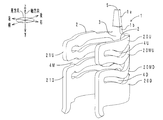
- FIG. 1 the layout of the clamp of this embodiment is shown.
- the injector 90 is attached to a fuel delivery pipe 91.
- the injector 90 is included in the concept of the “member to be gripped” of the present invention.
- the lower end (tip) of the injector 90 is inserted into the combustion chamber A inside the cylinder head 92.
- the clamp 1 (hatching) holds the outer peripheral surface of the injector 90.
- the clamp 1 is interposed between a step portion 910 that reduces the diameter of the fuel delivery pipe 91 downward and a step portion 900 that reduces the diameter of the injector 90 upward.
- combustion pressure is applied from the combustion chamber A to the injector 90. Under the combustion pressure, the injector 90 is lifted upward.
- the clamp 1 contracts in the vertical direction between the pair of upper and lower step portions 910 and 900. In this way, the clamp 1 reduces the impact applied to the injector 90.
- FIG. 2 the perspective view of the clamp of this embodiment is shown.
- FIG. 3 shows a front view of the clamp.
- FIG. 4 shows a top view of the clamp.
- FIG. 5 shows a right side view of the clamp.
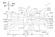
- FIG. 6 is a development view of the inner peripheral surface of the clamp. Note that FIG. 1 described above corresponds to a rear view of the clamp.
- the clamp 1 is made of metal and has a C-shape (a ring with ends) opened to the front side when viewed from the upper side (axial direction).
- the clamp 1 includes a clamp main body 1a and a surface layer (plating layer) 1b.
- the surface layer 1b is laminated on the surface of the clamp body 1a.
- the clamp 1 includes a pair of left and right arm portions 2, a back portion 3, a total of four slits 4U, 4M, and 4D, and a convex portion 5.
- the back portion 3 constitutes the rear portion of the clamp 1.
- the convex portion 5 projects upward from the upper edge of the back portion 3.
- the convex portion 5 is accommodated in the concave portion 911 of the fuel delivery pipe 91.
- the convex portion 5 defines the position of the clamp 1 with respect to the fuel delivery pipe 91, that is, the circumferential direction of the injector 90 (the circumferential direction centered on the center of gravity G of the clamp 1 when viewed from above as shown in FIG. 4). Yes.
- the arm portion 2 includes four beam portions 20U, 20MU, 20MD, and 20D, and two connecting portions 21U and 21D.
- the four beam portions 20U, 20MU, 20MD, and 20D are arranged in four rows in the vertical direction in this order.
- the four beam portions 20U, 20MU, 20MD, and 20D each extend in the circumferential direction.
- the upper connecting portion 21U includes a front end of the upper beam portion 20U (one end in the circumferential direction of the arm portion 2 (an end on the C-shaped opening side (the opposite side to the back portion 3)), a front end of the middle upper beam portion 20MU, Are connected in the vertical direction.
- the lower connecting portion 21D connects the front end of the middle lower beam portion 20MD and the front end of the lower beam portion 20D in the vertical direction.
- the four slits 4U, 4M, and 4D are arranged in three stages in the vertical direction in this order.
- the four slits 4U, 4M, and 4D each extend in the circumferential direction in a wavy shape.
- the upper slit 4U includes a pair of left and right arm sections 40U and a back section 41U.
- the pair of left and right arm sections 40U is disposed on the pair of left and right arms 2.
- the back section 41U is disposed on the back section 3. Both ends in the circumferential direction of the slit 4U are sealed by a pair of left and right connecting portions 21U. That is, the slit 4U is closed.
- the arm part section 40U includes an arm part side bending part 400U and a pair of front and rear arm part side hem parts 401U.
- the arm portion side bending portion 400U is disposed at the center in the circumferential direction of the arm portion section 40U.
- the arm side bending portion 400U is curved in an arc shape (C shape) on the lower side.
- the pair of front and rear arm portion side hem portions 401U are disposed on both sides in the circumferential direction of the arm portion side bending portion 400U.
- Each of the pair of front and rear arm side hems 401U has a linear shape extending in the circumferential direction. Based on the pair of front and rear arm portion side hem portions 401U, the arm portion side bending portion 400U protrudes downward.
- the back section 41U includes a back-side curved portion 410U and a pair of left and right back-side skirt portions 411U.
- the back portion side curved portion 410U is disposed at the center in the circumferential direction of the back portion 41U.
- the back portion side curved portion 410U is curved in an arc shape (C shape) on the lower side.
- the pair of left and right back side skirt portions 411U are disposed on both sides in the circumferential direction of the back side bending portion 410U.
- Each of the pair of left and right back side skirts 411U has a linear shape extending in the circumferential direction. Based on the pair of left and right back side skirts 411U, the back side bending portion 410U protrudes downward.
- the back side hem 411U is arranged at the same position in the vertical direction as the arm side skirt 401U. For this reason, the left back side skirt 411U and the rear arm part side skirt 401U of the left arm 2 are connected in a straight line. Similarly, the right back skirt 411U and the rear arm skirt 401U on the right arm 2 are connected in a straight line.
- the pair of left and right slits 4M in the middle stage are arranged on the pair of left and right arms 2.
- the configuration of the pair of left and right slits 4M is the same.
- the arrangement of the pair of left and right slits 4 ⁇ / b> M is symmetrical with respect to the back portion 3.
- the slit 4M includes an arm section 40M.
- the front end of the slit 4M one end in the circumferential direction of the arm portion 2 (the end on the C-shaped opening side (the side opposite to the back portion 3)) is open.
- the rear end of the slit 4M (the other end in the circumferential direction of the arm portion 2 (the end on the C-shaped bottom side (the back portion 3 side)) is closed.
- the configuration of the arm section 40M is the same as the configuration of the arm section 40U. That is, the arm part section 40M includes an arm part side bending part 400M and a pair of front and rear arm part side hem parts 401M. The arm portion side bending portion 400M is disposed directly below the arm portion side bending portion 400U.
- the configuration of the lower slit 4D is substantially the same as the configuration of the upper slit 4U. That is, the slit 4D includes a pair of left and right arm sections 40D and a back section 41D. Both ends in the circumferential direction of the slit 4D are sealed by a pair of left and right connecting portions 21D. That is, the slit 4D is closed.
- the arm section 40D includes an arm section side bending section 400D and a pair of front and rear arm section side skirt sections 401D.
- the arm portion side bending portion 400D is disposed directly below the arm portion side bending portion 400M.
- the back section 41D includes a back-side curved portion 410D and a pair of left and right back-side skirt portions 411D.
- the back portion side bending portion 410D is disposed directly below the back portion side bending portion 410U. However, unlike the back portion side bending portion 410U, the back portion side bending portion 410D is curved in an arc shape (C shape) on the upper side. Based on the pair of left and right back side skirts 411D, the back side bending part 410D protrudes upward.
- the back portion side skirt portion 411D is disposed below the arm portion side skirt portion 401D. For this reason, the left back side skirt part 411D and the rear arm part side skirt part 401D of the left arm part 2 are connected in a step shape (crank shape). Similarly, the right back side skirt 411D and the rear arm part side skirt 401D of the right arm 2 are connected in steps.
- the width (however, the direction perpendicular to the extending direction of the slit (the extending direction of the wavy line)) of the slit 4M in the middle stage (however, The width of the arc-shaped groove bottom of the closed end of the slit 4M on the back 3 side and the chamfered portion of the open end of the slit 4M on the arm 2 side is from the rear side (back side) to the front side (arm part). Gradually increases toward the side).
- the width in the short direction of the upper and lower slits 4U, 4D is respectively It is constant over the entire length in the circumferential direction.
- the curvatures of the upper and lower three-stage arm side bending portions 400U, 400M, and 400D are substantially the same.
- the curvatures of the upper and lower two-stage back side curved portions 410U and 410D are substantially the same.
- FIG. 7 shows a view in the VII direction (circumferential direction) of the circumferential end surface of the connecting portion shown in FIG.
- a shape obtained by viewing the circumferential end face of the upper connecting portion 21U from the circumferential direction is referred to as a reference shape B.
- the reference shape B has a rectangular shape with a lateral width (thickness) C and a vertical width D.
- the reference shape of the circumferential end surface of the lower connecting portion 21D is larger than the reference shape B of the upper connecting portion 21U.
- the reference shape related to the lower connecting portion 21D has a longer vertical width D than the reference shape B shown in FIG.
- the arm portion side hem portion 401 ⁇ / b> D on the rear side of the arm portion side bending portion 400 ⁇ / b> D has a shape that does not include the reference shape B. .
- the arm side hem 401D (including a part of the back side hem 411D is included at a position shifted upward from the lower edge of the arm side hem 401D by the width C in the left-right direction of the reference shape B. ) Is set to be less than the vertical width D of the reference shape B.
- the arm portion side skirt portion 401U and the arm portion side skirt portion 401M each have a shape that does not include the reference shape B.
- the arm side bending portions 400U, 400M, and 400D each have a shape that does not include the reference shape B.
- the back side hems 411U and 411D each have a shape that does not include the reference shape B when viewed from the rear side (the X direction outer side shown in FIG. 4).
- the back side curved portions 410U and 410D each have a shape that the reference shape B does not enter.
- the manufacturing method of the clamp 1 has a punching process, a bending process, and a plating process.
- a semi-processed product (clamp body 1a in the middle of processing) of the clamp body 1a is punched out from a metal flat plate (the thickness is the width C in the left-right direction of the reference shape B shown in FIG. 7).
- the clamp main body 1a is produced by curving the semi-processed product of the flat clamp main body 1a into a C-shaped plate.
- a surface layer (plating layer) 1b is formed on the surface of the clamp body 1a. In this way, the clamp 1 is manufactured.
- a polishing step for example, barrel polishing
- the effect of the clamp of this embodiment is demonstrated.
- the clamp 1 is formed with slits 4U, 4M, and 4D.
- another clamp 1 for example, the connecting portion 21U shown in FIG. 2 enters the slits 4U, 4M, and 4D of the arbitrary clamp 1
- the plurality of clamps 1 are easily entangled with each other.
- the plurality of clamps 1 are easily entangled with each other.
- the plurality of clamps 1 are easily entangled with each other. In particular, this tendency becomes remarkable when the production amount of the clamp 1 is large.
- the surface layer 1b is hard to be formed in the part of the surface of the clamp body 1a that is intertwined with another clamp body 1a (the part that is in contact with another clamp body 1a).
- arm portion side bending portions 400U, 400M, and 400D are arranged in the arm portion sections 40U, 40M, and 40D of the slits 4U, 4M, and 4D. For this reason, it is difficult for another clamp 1 to enter the slits 4U, 4M, and 4D of an arbitrary clamp 1. Therefore, according to the clamp 1 of the present embodiment, the entanglement between the plurality of clamps 1 can be suppressed.
- the thickness of the clamp 1 (the lateral width C of the reference shape B shown in FIG. 7) is set to the slit 4U. It is conceivable to make the width larger than the width in the short direction of 4M and 4D. However, in this case, the weight of the clamp 1 becomes heavy. Moreover, the rigidity of the clamp 1 will become high as a whole. Further, if the vertical widths of the beam portions 20U, 20MU, 20MD, and 20D are reduced in order to avoid the rigidity increase, the widths of the slits 4U, 4M, and 4D in the short direction are increased. For this reason, the wall thickness of the clamp 1 will become smaller than the width
- the slits 4U, 4M, 4D of the arbitrary clamp 1 can be obtained without increasing the thickness of the clamp 1 (of course, this case is also included in claim 1 of the present application). Can be prevented from entering another clamp 1. For this reason, the setting freedom with respect to the thickness of the clamp 1 and the shapes of the slits 4U, 4M, and 4D is increased.
- FIG. 8 shows a right side view of the clamp according to the present embodiment in a contracted state.
- FIG. 8 shows a right side view of the clamp according to the present embodiment in a contracted state.
- FIG. 8 shows a right side view of the clamp according to the present embodiment in a contracted state.
- the arm portion side bending portions 400U, 400M, 400D are arranged in the center in the front-rear direction (circumferential direction) of the arm portion sections 40U, 40M, 40D.
- stress is less likely to concentrate than in the vicinity of both ends in the circumferential direction surrounded by an ellipse. For this reason, plastic deformation (sagging) hardly occurs in the clamp 1.
- the arm side bending portions 400U, 400M, and 400D are arranged in the center in the front-rear direction (circumferential direction) of the arm section sections 40U, 40M, and 40D, the arm side bending portions 400U, 400M, and 400D are also viewed from the front side. It is difficult for another clamp 1 to enter the slits 4U, 4M, and 4D from the rear side.
- back side curved portions 410U and 410D are disposed in the back sections 41U and 41D of the slits 4U and 4D. Also in this point, it is difficult for another clamp 1 to enter the slits 4U, 4M, and 4D of an arbitrary clamp 1.
- the slits 4U, 4M, and 4D extend in the circumferential direction in the form of wavy lines (the amplitude direction is the axial direction). Also in this point, it is difficult for another clamp 1 to enter the slits 4U, 4M, and 4D of an arbitrary clamp 1.
- the left back side skirt 411D and the rear arm side skirt 401D of the left arm 2 are connected in a step shape.
- the right back side skirt 411D and the rear arm part side skirt 401D of the right arm 2 are connected in steps. Also in this point, it is difficult for another clamp 1 to enter the slit 4D of an arbitrary clamp 1.
- the rear arm portion side skirt portion 401 ⁇ / b> D of the arm portion side bending portion 400 ⁇ / b> D has a reference shape B (a plurality of connecting portions 21 ⁇ / b> U).
- the minimum reference shape is not included.
- the arm side hem 401U and the rear arm hem 401M each have a shape that does not include the reference shape B.
- the arm side bending portions 400U, 400M, and 400D each have a shape that does not include the reference shape B.
- the back side hems 411U and 411D each have a shape that does not include the reference shape B when viewed from the rear side (the X direction outer side shown in FIG. 4). Further, as viewed from the rear side, the back side curved portions 410U and 410D each have a shape that the reference shape B does not enter. Also in this point, it is difficult for another clamp 1 to enter the slits 4U, 4M, and 4D of an arbitrary clamp 1.
- the clamp 1 has a forward C-shaped opening.
- both ends in the circumferential direction of the clamp 1 (the front end of the left arm portion 2 and the front end of the right arm portion 2) have lower vertical rigidity than the circumferential center (back portion 3) of the clamp 1.
- one end in the circumferential direction of the middle slit 4M (an end (front end) on the C-shaped opening side) is open.
- the rigidity in the vertical direction in the vicinity of one end in the circumferential direction of the slit 4M is particularly low.
- the width in the short direction of the slit 4M in the middle stage is from the back side to the arm side. It is getting bigger gradually. For this reason, a sufficient amount of vertical contraction stroke can be secured near one end in the circumferential direction of the low-rigidity slit 4M.
- the width in the short direction of the upper and lower slits 4U, 4D is constant over the entire length in the circumferential direction. For this reason, the dispersion
- the widths of all the slits 4U, 4M, and 4D shown in FIG. 6 in the short direction may be constant over the entire length in the circumferential direction. . If it carries out like this, the dispersion
- the shape, size, position, and number of arrangements (hereinafter referred to as “shape etc.”) of the bending portions are not particularly limited.
- the shape may be a C shape, a V shape, a U shape, a rectangular shape, or the like.
- the protruding direction of the curved portion is not particularly limited.
- the protruding direction may be upward or downward.
- the shape and the like of the skirts are not particularly limited.
- the shape may be linear, curved, or the like. Further, the skirts on both sides in the circumferential direction of an arbitrary bending portion may have different shapes.
- ⁇ A skirt may be arranged only on one side in the circumferential direction of an arbitrary curved portion. Further, the skirt portion may not be arranged. For example, a plurality of curved portions having different projecting directions may be alternately connected in the circumferential direction without using the skirt portion.
- the arm side bending portions 400U, 400M, and 400D may not overlap. That is, the arm side bending portions 400U, 400M, and 400D may be displaced from each other in the circumferential direction. The same applies to the back side curved portions 410U and 410D.
- slits (closed slits) 4U and 4D whose both ends in the circumferential direction are closed and slits (open slits) 4M whose one end in the circumferential direction are opened alternately in the vertical direction.
- the closed slits and the open slits may not be arranged alternately.
- a plurality of open slits may be arranged adjacent to each other in the vertical direction.
- a plurality of closed slits may be arranged adjacent to each other in the vertical direction.
- only a plurality of open slits may be arranged in the clamp 1.
- only a plurality of closed slits may be arranged in the clamp 1.
- the type (surface treatment type) of the surface layer 1b covering the surface of the clamp body 1a is not particularly limited.
- the surface layer 1b may be, for example, a plating layer, a vapor deposition layer, a thermal spray layer, a lining layer, a coating layer, a coating layer, a chromate treatment layer, a carburized layer, a quenching layer, a shot peening layer, or the like.
- the material of the surface layer 1b may be metal, resin, ceramic, or the like.
- the arrangement direction of the clamp 1 (that is, the arrangement direction of the injector 90) is not particularly limited.
- the axial direction of the clamp 1 may be a horizontal direction or an oblique direction (an intermediate direction between the vertical direction and the horizontal direction).
- the clamp 1 may be an endless ring.
- the type of member to be gripped is not particularly limited.
- a hose may be used.
Landscapes
- Engineering & Computer Science (AREA)
- General Engineering & Computer Science (AREA)
- Mechanical Engineering (AREA)
- Chemical & Material Sciences (AREA)
- Combustion & Propulsion (AREA)
- Clamps And Clips (AREA)
- Fuel-Injection Apparatus (AREA)
Abstract
複数のクランプ(1)同士の絡み合いを抑制可能なクランプ(1)を提供することを課題とする。クランプ(1)は、被把持部材(90)を把持する一対の腕部(2)と、一対の腕部(2)の周方向中間に配置される背部(3)と、腕部(2)に配置される腕部区間(40U、40M、40D)を有するスリット(4U、4M、4D)と、を備える。腕部区間(40U、40M、40D)には、軸方向に弧状に湾曲する腕部側湾曲部(400U、400M、400D)が配置される。
Description
本発明は、例えばインジェクターなどの被把持部材を把持するために用いられるクランプに関する。
特許文献1には、インジェクターを把持するクランプが開示されている。クランプの製造方法は、打ち抜き工程、曲げ工程、めっき工程を有している。打ち抜き工程においては、金属製の平板からクランプ本体の半加工品を打ち抜く。曲げ工程においては、平板状のクランプ本体の半加工品をC字板状に湾曲させることにより、クランプ本体を作製する。めっき工程においては、クランプ本体の表面に表層(めっき層)を形成する。このようにして、クランプが製造される。
しかしながら、めっき工程においては、複数のクランプ本体を、めっき液が張り込まれた同一のめっき槽に浸漬させている。このため、複数のクランプ同士(複数の「クランプ本体同士」、複数の「クランプとクランプ本体」を含む。以下同様。)が絡み合いやすい。具体的には、クランプにはスリットが形成されている。任意のクランプのスリットに別のクランプが入り込むことにより、複数のクランプ同士が絡み合ってしまう。同様に、クランプ本体あるいはクランプの搬送中においても、複数のクランプ同士が絡み合いやすい。特に、クランプの製造量が多い場合、この傾向は顕著になる。複数のクランプ同士が絡み合った場合、絡み合った複数のクランプを、逐一作業者が解す必要がある。また、クランプ本体の表面のうち、別のクランプ本体と絡み合っていた部分(別のクランプ本体と接触していた部分)には、表層が形成されにくい。
そこで、本発明は、複数のクランプ同士の絡み合いを抑制可能なクランプを提供することを目的とする。
上記課題を解決するため、本発明のクランプは、被把持部材を把持する一対の腕部と、一対の前記腕部の周方向中間に配置される背部と、前記腕部に配置される腕部区間を有するスリットと、を備えるクランプであって、前記腕部区間には、軸方向に弧状に湾曲する腕部側湾曲部が配置されることを特徴とする。
スリットは湾曲している。すなわち、スリットの腕部区間には、腕部側湾曲部が配置されている。このため、任意のクランプのスリットに別のクランプが入り込みにくい。したがって、本発明のクランプによると、複数のクランプ同士の絡み合いを抑制することができる。
以下、本発明のクランプの実施の形態について説明する。以下の図において、上下方向は本発明の「軸方向」に、前後方向は本発明の「X方向」に、左右方向は本発明の「Y方向」に、各々対応している。
<クランプの配置>
まず、本実施形態のクランプの配置について説明する。図1に、本実施形態のクランプの配置図を示す。図1に示すように、インジェクター90は、燃料デリバリパイプ91に取り付けられている。インジェクター90は、本発明の「被把持部材」の概念に含まれる。インジェクター90の下端(先端)は、シリンダヘッド92内部の燃焼室Aに挿入されている。クランプ1(ハッチングを施す)は、インジェクター90の外周面を把持している。また、クランプ1は、燃料デリバリパイプ91の下向きに縮径する段部910と、インジェクター90の上向きに縮径する段部900と、の間に介装されている。エンジン駆動時においては、燃焼室Aからインジェクター90に、燃焼圧が加わる。当該燃焼圧を受け、インジェクター90は上側に持ち上がる。この際、クランプ1は、上下一対の段部910、900間において、上下方向に収縮する。このように、クランプ1は、インジェクター90に加わる衝撃を緩和している。
まず、本実施形態のクランプの配置について説明する。図1に、本実施形態のクランプの配置図を示す。図1に示すように、インジェクター90は、燃料デリバリパイプ91に取り付けられている。インジェクター90は、本発明の「被把持部材」の概念に含まれる。インジェクター90の下端(先端)は、シリンダヘッド92内部の燃焼室Aに挿入されている。クランプ1(ハッチングを施す)は、インジェクター90の外周面を把持している。また、クランプ1は、燃料デリバリパイプ91の下向きに縮径する段部910と、インジェクター90の上向きに縮径する段部900と、の間に介装されている。エンジン駆動時においては、燃焼室Aからインジェクター90に、燃焼圧が加わる。当該燃焼圧を受け、インジェクター90は上側に持ち上がる。この際、クランプ1は、上下一対の段部910、900間において、上下方向に収縮する。このように、クランプ1は、インジェクター90に加わる衝撃を緩和している。
<クランプの構成>
次に、本実施形態のクランプの構成について説明する。図2に、本実施形態のクランプの斜視図を示す。図3に、同クランプの前面図を示す。図4に、同クランプの上面図を示す。図5に、同クランプの右面図を示す。図6に、同クランプの内周面の展開図を示す。なお、前述の図1は、同クランプの後面図に相当する。
次に、本実施形態のクランプの構成について説明する。図2に、本実施形態のクランプの斜視図を示す。図3に、同クランプの前面図を示す。図4に、同クランプの上面図を示す。図5に、同クランプの右面図を示す。図6に、同クランプの内周面の展開図を示す。なお、前述の図1は、同クランプの後面図に相当する。
図4に示すように、クランプ1は、金属製であって、上側(軸方向)から見て、前側に開口するC字状(有端環状)を呈している。図2に示すように、クランプ1は、クランプ本体1a、と表層(めっき層)1bと、を備えている。表層1bは、クランプ本体1aの表面に積層されている。クランプ1は、左右一対の腕部2と、背部3と、合計四つのスリット4U、4M、4Dと、凸部5と、を備えている。
(背部3、凸部5)
背部3は、クランプ1の後側部分を構成している。凸部5は、背部3の上縁から上側に突出している。図1に示すように、凸部5は、燃料デリバリパイプ91の凹部911に収容されている。凸部5は、燃料デリバリパイプ91に対するクランプ1、つまりインジェクター90の周方向(図4に示すように、上側から見た場合のクランプ1の重心Gを中心とする周方向)位置を規定している。
背部3は、クランプ1の後側部分を構成している。凸部5は、背部3の上縁から上側に突出している。図1に示すように、凸部5は、燃料デリバリパイプ91の凹部911に収容されている。凸部5は、燃料デリバリパイプ91に対するクランプ1、つまりインジェクター90の周方向(図4に示すように、上側から見た場合のクランプ1の重心Gを中心とする周方向)位置を規定している。
(腕部2)
図6に示すように、左右一対の腕部2は、背部3の周方向両側に配置されている。左右一対の腕部2の構成は同様である。左右一対の腕部2の配置は、背部3を挟んで、左右対称である。以下、代表して、右側の腕部2の構成について説明する。腕部2は、四つの梁部20U、20MU、20MD、20Dと、二つの連結部21U、21Dと、を備えている。四つの梁部20U、20MU、20MD、20Dは、この順番で、上下方向に四段に並んでいる。四つの梁部20U、20MU、20MD、20Dは、各々、周方向に延在している。
図6に示すように、左右一対の腕部2は、背部3の周方向両側に配置されている。左右一対の腕部2の構成は同様である。左右一対の腕部2の配置は、背部3を挟んで、左右対称である。以下、代表して、右側の腕部2の構成について説明する。腕部2は、四つの梁部20U、20MU、20MD、20Dと、二つの連結部21U、21Dと、を備えている。四つの梁部20U、20MU、20MD、20Dは、この順番で、上下方向に四段に並んでいる。四つの梁部20U、20MU、20MD、20Dは、各々、周方向に延在している。
上側の連結部21Uは、上段の梁部20Uの前端(腕部2の周方向一端(C字開口側(背部3と反対側)の端))と、中上段の梁部20MUの前端と、を上下方向に連結している。下側の連結部21Dは、中下段の梁部20MDの前端と、下段の梁部20Dの前端と、を上下方向に連結している。
(スリット4U、4M、4D)
四つのスリット4U、4M、4Dは、この順番で、上下方向に三段に並んでいる。四つのスリット4U、4M、4Dは、各々、波線状に、周方向に延在している。
四つのスリット4U、4M、4Dは、この順番で、上下方向に三段に並んでいる。四つのスリット4U、4M、4Dは、各々、波線状に、周方向に延在している。
上段のスリット4Uは、左右一対の腕部区間40Uと、背部区間41Uと、を備えている。左右一対の腕部区間40Uは、左右一対の腕部2に配置されている。背部区間41Uは、背部3に配置されている。スリット4Uの周方向両端は、左右一対の連結部21Uにより、封止されている。すなわち、スリット4Uは閉塞されている。
腕部区間40Uは、腕部側湾曲部400Uと、前後一対の腕部側裾部401Uと、を備えている。腕部側湾曲部400Uは、腕部区間40Uの周方向中央に配置されている。腕部側湾曲部400Uは、下側に弧状(C字状)に湾曲している。前後一対の腕部側裾部401Uは、腕部側湾曲部400Uの周方向両側に配置されている。前後一対の腕部側裾部401Uは、各々、周方向に延在する直線状を呈している。前後一対の腕部側裾部401Uを基準として、腕部側湾曲部400Uは、下側に突出している。
背部区間41Uは、背部側湾曲部410Uと、左右一対の背部側裾部411Uと、を備えている。背部側湾曲部410Uは、背部区間41Uの周方向中央に配置されている。背部側湾曲部410Uは、下側に弧状(C字状)に湾曲している。左右一対の背部側裾部411Uは、背部側湾曲部410Uの周方向両側に配置されている。左右一対の背部側裾部411Uは、各々、周方向に延在する直線状を呈している。左右一対の背部側裾部411Uを基準として、背部側湾曲部410Uは、下側に突出している。
背部側裾部411Uは、腕部側裾部401Uと、上下方向同位置に配置されている。このため、左側の背部側裾部411Uと、左側の腕部2の後側の腕部側裾部401Uと、は直線状に連なっている。同様に、右側の背部側裾部411Uと、右側の腕部2の後側の腕部側裾部401Uと、は直線状に連なっている。
中段の左右一対のスリット4Mは、左右一対の腕部2に配置されている。左右一対のスリット4Mの構成は同様である。左右一対のスリット4Mの配置は、背部3を挟んで、左右対称である。以下、代表して、右側のスリット4Mの構成について説明する。スリット4Mは、腕部区間40Mを備えている。スリット4Mの前端(腕部2の周方向一端(C字開口側(背部3と反対側)の端))は、開放されている。一方、スリット4Mの後端(腕部2の周方向他端(C字底側(背部3側)の端))は、閉塞されている。
腕部区間40Mの構成は、腕部区間40Uの構成と同様である。すなわち、腕部区間40Mは、腕部側湾曲部400Mと、前後一対の腕部側裾部401Mと、を備えている。腕部側湾曲部400Mは、腕部側湾曲部400Uの真下に配置されている。
下段のスリット4Dの構成は、上段のスリット4Uの構成とほぼ同様である。すなわち、スリット4Dは、左右一対の腕部区間40Dと、背部区間41Dと、を備えている。スリット4Dの周方向両端は、左右一対の連結部21Dにより、封止されている。すなわち、スリット4Dは閉塞されている。腕部区間40Dは、腕部側湾曲部400Dと、前後一対の腕部側裾部401Dと、を備えている。腕部側湾曲部400Dは、腕部側湾曲部400Mの真下に配置されている。背部区間41Dは、背部側湾曲部410Dと、左右一対の背部側裾部411Dと、を備えている。背部側湾曲部410Dは、背部側湾曲部410Uの真下に配置されている。ただし、背部側湾曲部410Uと異なり、背部側湾曲部410Dは、上側に弧状(C字状)に湾曲している。左右一対の背部側裾部411Dを基準として、背部側湾曲部410Dは、上側に突出している。
背部側裾部411Dは、腕部側裾部401Dよりも、下側に配置されている。このため、左側の背部側裾部411Dと、左側の腕部2の後側の腕部側裾部401Dと、は段状(クランク状)に連なっている。同様に、右側の背部側裾部411Dと、右側の腕部2の後側の腕部側裾部401Dと、は段状に連なっている。
燃焼室Aから燃焼圧が加わっていない状態(無荷重状態)において、中段のスリット4Mの短手方向(スリットの延在方向(波線の延在方向)に対して直交する方向)の幅(ただし、スリット4Mの背部3側の閉塞端の弧状の溝底部、およびスリット4Mの腕部2側の開放端の面取部を除く部分の幅)は、後側(背部側)から前側(腕部側)に向かって、徐々に大きくなっている。これに対して、上下段のスリット4U、4Dの短手方向の幅(ただし、スリット4U、4Dの左右の腕部2側の閉塞端の弧状の溝底部を除く部分の幅)は、各々、周方向全長に亘って一定である。また、上下三段の腕部側湾曲部400U、400M、400Dの曲率は、略一致している。上下二段の背部側湾曲部410U、410Dの曲率は、略一致している。
図7に、図6に示す連結部の周方向端面のVII方向(周方向)視図を示す。上側の連結部21Uの周方向端面を周方向から見た形状を、基準形状Bとする。基準形状Bは、左右方向幅(肉厚)C、上下方向幅Dの四角形状を呈している。なお、下側の連結部21Dの周方向端面の基準形状は、上側の連結部21Uの基準形状Bよりも大きい。具体的には、下側の連結部21Dに関する基準形状は、図7に示す基準形状Bよりも、上下方向幅Dが長い。
図5に示すように、右側(図4に示すY方向外側)から見て、腕部側湾曲部400Dの後側の腕部側裾部401Dは、基準形状Bが入らない形状を呈している。具体的には、腕部側裾部401Dの下縁から、基準形状Bの左右方向幅Cだけ、上側にシフトした位置における、腕部側裾部401D(背部側裾部411Dの一部を含む)の前後方向幅Eは、基準形状Bの上下方向幅D未満に設定されている。同様に、右側から見て、腕部側裾部401U、腕部側裾部401M(ただし、後側の腕部側裾部401M)は、各々、基準形状Bが入らない形状を呈している。また、右側から見て、腕部側湾曲部400U、400M、400Dは、各々、基準形状Bが入らない形状を呈している。また、図1、図3に示すように、後側(図4に示すX方向外側)から見て、背部側裾部411U、411Dは、各々、基準形状Bが入らない形状を呈している。また、後側から見て、背部側湾曲部410U、410Dは、各々、基準形状Bが入らない形状を呈している。
<クランプの製造方法>
次に、本実施形態のクランプの製造方法について説明する。クランプ1の製造方法は、打ち抜き工程、曲げ工程、めっき工程を有している。打ち抜き工程においては、金属製の平板(板厚は、図7に示す基準形状Bの左右方向幅C)から、クランプ本体1aの半加工品(加工途中のクランプ本体1a)を打ち抜く。曲げ工程においては、平板状のクランプ本体1aの半加工品をC字板状に湾曲させることにより、クランプ本体1aを作製する。めっき工程においては、クランプ本体1aの表面に表層(めっき層)1bを形成する。このようにして、クランプ1が製造される。なお、適宜、研磨工程(例えばバレル研磨など)が追加される場合もある。
次に、本実施形態のクランプの製造方法について説明する。クランプ1の製造方法は、打ち抜き工程、曲げ工程、めっき工程を有している。打ち抜き工程においては、金属製の平板(板厚は、図7に示す基準形状Bの左右方向幅C)から、クランプ本体1aの半加工品(加工途中のクランプ本体1a)を打ち抜く。曲げ工程においては、平板状のクランプ本体1aの半加工品をC字板状に湾曲させることにより、クランプ本体1aを作製する。めっき工程においては、クランプ本体1aの表面に表層(めっき層)1bを形成する。このようにして、クランプ1が製造される。なお、適宜、研磨工程(例えばバレル研磨など)が追加される場合もある。
<作用効果>
次に、本実施形態のクランプの作用効果について説明する。クランプ1の製造方法のめっき工程においては、複数のクランプ本体1aを、めっき液が張り込まれた同一のめっき槽に浸漬させている。このため、複数のクランプ1同士が絡み合いやすい。具体的には、クランプ1にはスリット4U、4M、4Dが形成されている。任意のクランプ1のスリット4U、4M、4Dに別のクランプ1(例えば図2に示す連結部21U)が入り込むことにより、複数のクランプ1同士が絡み合いやすい。同様に、研磨工程においても、複数のクランプ1同士が絡み合いやすい。同様に、クランプ本体1aあるいはクランプ1の搬送中においても、複数のクランプ1同士が絡み合いやすい。特に、クランプ1の製造量が多い場合、この傾向は顕著になる。複数のクランプ1同士が絡み合った場合、絡み合った複数のクランプ1を、逐一作業者が解す必要がある。また、クランプ本体1aの表面のうち、別のクランプ本体1aと絡み合っていた部分(別のクランプ本体1aと接触していた部分)には、表層1bが形成されにくい。
次に、本実施形態のクランプの作用効果について説明する。クランプ1の製造方法のめっき工程においては、複数のクランプ本体1aを、めっき液が張り込まれた同一のめっき槽に浸漬させている。このため、複数のクランプ1同士が絡み合いやすい。具体的には、クランプ1にはスリット4U、4M、4Dが形成されている。任意のクランプ1のスリット4U、4M、4Dに別のクランプ1(例えば図2に示す連結部21U)が入り込むことにより、複数のクランプ1同士が絡み合いやすい。同様に、研磨工程においても、複数のクランプ1同士が絡み合いやすい。同様に、クランプ本体1aあるいはクランプ1の搬送中においても、複数のクランプ1同士が絡み合いやすい。特に、クランプ1の製造量が多い場合、この傾向は顕著になる。複数のクランプ1同士が絡み合った場合、絡み合った複数のクランプ1を、逐一作業者が解す必要がある。また、クランプ本体1aの表面のうち、別のクランプ本体1aと絡み合っていた部分(別のクランプ本体1aと接触していた部分)には、表層1bが形成されにくい。
この点、図6に示すように、スリット4U、4M、4Dの腕部区間40U、40M、40Dには、腕部側湾曲部400U、400M、400Dが配置されている。このため、任意のクランプ1のスリット4U、4M、4Dに別のクランプ1が入り込みにくい。したがって、本実施形態のクランプ1によると、複数のクランプ1同士の絡み合いを抑制することができる。
なお、任意のクランプ1のスリット4U、4M、4Dに対する別のクランプ1の進入を抑制するためには、クランプ1の肉厚(図7に示す基準形状Bの左右方向幅C)を、スリット4U、4M、4Dの短手方向の幅よりも、大きくすることも考えられる。しかしながら、この場合、クランプ1の重量が重くなってしまう。また、クランプ1の剛性が全体的に高くなってしまう。また、当該剛性アップを回避するために梁部20U、20MU、20MD、20Dの上下方向の幅を小さくすると、スリット4U、4M、4Dの短手方向の幅が大きくなってしまう。このため、クランプ1の肉厚が、スリット4U、4M、4Dの短手方向の幅よりも、小さくなってしまう。
これに対して、本実施形態のクランプ1によると、クランプ1の肉厚を大きくする(勿論、この場合も本願請求項1に含まれる)ことなく、任意のクランプ1のスリット4U、4M、4Dに対する別のクランプ1の進入を抑制することができる。このため、クランプ1の肉厚や、スリット4U、4M、4Dの形状に対する、設定の自由度が高くなる。
図8に、本実施形態のクランプの収縮状態における右面図を示す。なお、図5と対応する部位については、同じ符号で示す。図8に示すように、図1に示す燃焼室Aから燃焼圧Fが加わると、クランプ1は、上下方向に収縮する。この際、スリット4U、4M、4Dは、上下方向に圧縮される。このため、楕円(一点鎖線)で囲むように、梁部20MU、20MDの前後方向(周方向)両端部付近に、応力が集中する。したがって、仮に、この部分に腕部側湾曲部400U、400M、400Dが配置されている場合(勿論、この場合も本願請求項1に含まれる)、クランプ1に塑性変形(へたり)が発生しやすくなる。
この点、本実施形態のクランプ1によると、腕部側湾曲部400U、400M、400Dが腕部区間40U、40M、40Dの前後方向(周方向)中央に配置されている。周方向中央は、楕円で囲む周方向両端部付近と比較して、応力が集中しにくい。このため、クランプ1に塑性変形(へたり)が発生しにくくなる。
また、腕部側湾曲部400U、400M、400Dが腕部区間40U、40M、40Dの前後方向(周方向)中央に配置されているため、腕部側湾曲部400U、400M、400Dの前側からも後側からも、スリット4U、4M、4Dに別のクランプ1が入り込みにくい。
また、図6に示すように、スリット4U、4Dの背部区間41U、41Dには、背部側湾曲部410U、410Dが配置されている。この点においても、任意のクランプ1のスリット4U、4M、4Dに別のクランプ1が入り込みにくい。
また、図6に示すように、スリット4U、4M、4Dは、波線(振幅方向は軸方向)状に周方向に延在している。この点においても、任意のクランプ1のスリット4U、4M、4Dに別のクランプ1が入り込みにくい。
また、図6に示すように、左側の背部側裾部411Dと、左側の腕部2の後側の腕部側裾部401Dと、は段状に連なっている。同様に、右側の背部側裾部411Dと、右側の腕部2の後側の腕部側裾部401Dと、は段状に連なっている。この点においても、任意のクランプ1のスリット4Dに別のクランプ1が入り込みにくい。
また、図5に示すように、右側(図4に示すY方向外側)から見て、腕部側湾曲部400Dの後側の腕部側裾部401Dは、基準形状B(複数の連結部21U、21Dの基準形状のうち、最小の基準形状)が入らない形状を呈している。同様に、右側から見て、腕部側裾部401U、後側の腕部側裾部401Mは、各々、基準形状Bが入らない形状を呈している。また、右側から見て、腕部側湾曲部400U、400M、400Dは、各々、基準形状Bが入らない形状を呈している。また、図1、図3に示すように、後側(図4に示すX方向外側)から見て、背部側裾部411U、411Dは、各々、基準形状Bが入らない形状を呈している。また、後側から見て、背部側湾曲部410U、410Dは、各々、基準形状Bが入らない形状を呈している。この点においても、任意のクランプ1のスリット4U、4M、4Dに別のクランプ1が入り込みにくい。
また、図2に示すように、クランプ1は、前向きのC字開口を備えている。このため、クランプ1の周方向両端(左側の腕部2の前端および右側の腕部2の前端)は、クランプ1の周方向中央(背部3)と比較して、上下方向の剛性が低い。並びに、中段のスリット4Mの周方向一端(C字開口側の端(前端))は、開放されている。このため、特に、スリット4Mの周方向一端付近の上下方向の剛性は低い。
この点、本実施形態のクランプ1によると、図6に示すように、燃焼室Aから燃焼圧が加わっていない状態において、中段のスリット4Mの短手方向の幅は、背部側から腕部側に向かって、徐々に大きくなっている。このため、低剛性のスリット4Mの周方向一端付近に、充分量の上下方向の収縮ストロークを確保することができる。
また、上下段のスリット4U、4Dの短手方向の幅は、各々、周方向全長に亘って一定である。このため、周方向全長に亘って、上下方向の収縮ストロークのばらつきを抑制することができる。
<その他>
以上、本発明のクランプの実施の形態について説明した。しかしながら、実施の形態は上記形態に特に限定されるものではない。当業者が行いうる種々の変形的形態、改良的形態で実施することも可能である。
以上、本発明のクランプの実施の形態について説明した。しかしながら、実施の形態は上記形態に特に限定されるものではない。当業者が行いうる種々の変形的形態、改良的形態で実施することも可能である。
例えば、図6に示す全てのスリット4U、4M、4Dの短手方向の幅(ただし、スリット4Mの場合は、背部3側の閉塞端の弧状の溝底部、および腕部2側の開放端の面取部を除く部分の幅。スリット4U、4Dの場合は、左右の腕部2側の閉塞端の弧状の溝底部を除く部分の幅。)を、周方向全長に亘って一定としてもよい。こうすると、周方向全長に亘って、上下方向の収縮ストロークのばらつきを抑制することができる。
湾曲部(腕部側湾曲部400U、400M、400D、背部側湾曲部410U、410D)の形状、大きさ、位置、配置数(以下、「形状等」と称す)は特に限定しない。例えば、形状は、C字状、V字状、U字状、矩形状などであってもよい。湾曲部の突出方向は特に限定しない。例えば、突出方向は、上向きでも下向きでもよい。同様に、裾部(腕部側裾部401U、401M、401D、背部側裾部411U、411D)の形状等は特に限定しない。例えば、形状は、直線状、曲線状などであってもよい。また、任意の湾曲部の周方向両側の裾部が、互いに異なる形状であってもよい。
任意の湾曲部の周方向片側だけに裾部を配置してもよい。また、裾部は配置しなくてもよい。例えば、突出方向の異なる複数の湾曲部が、裾部を介さずに、交互に周方向に連なっていてもよい。上側から見て、腕部側湾曲部400U、400M、400Dが重複していなくてもよい。すなわち、腕部側湾曲部400U、400M、400Dが周方向に互いにずれていてもよい。背部側湾曲部410U、410Dについても同様である。
図6に示すように、クランプ1においては、周方向両端が閉塞されたスリット(閉スリット)4U、4Dと、周方向一端が開放されたスリット(開スリット)4Mと、が上下方向に交互に配置されている。しかしながら、閉スリットと開スリットが交互に配置されていなくてもよい。例えば、複数の開スリットを上下方向に隣り合わせに配置してもよい。また、複数の閉スリットを上下方向に隣り合わせに配置してもよい。また、クランプ1に、複数の開スリットだけを配置してもよい。また、クランプ1に、複数の閉スリットだけを配置してもよい。
また、クランプ本体1aの表面を覆う表層1bの種類(表面処理の種類)は特に限定しない。表層1bは、例えば、めっき層、蒸着層、溶射層、ライニング層、コーティング層、塗膜層、クロメート処理層、浸炭層、焼入れ層、ショットピーニング層などであってもよい。また、表層1bの材質は、金属、樹脂、セラミックなどであってもよい。
また、クランプ1の配置方向(つまりインジェクター90の配置方向)は特に限定しない。例えば、クランプ1の軸方向が、水平方向や斜め方向(上下方向と水平方向との中間方向)であってもよい。また、クランプ1は、無端環状であってもよい。
被把持部材の種類は特に限定しない。例えば、ホースなどであってもよい。また、本発明のクランプを、「スリットにより軸方向の収縮ストロークを確保する圧縮ばね」として用いてもよい。
1:クランプ、1a:クランプ本体、1b:表層、2:腕部、3:背部、4D:スリット、4M:スリット、4U:スリット、5:凸部、20D:梁部、20MD:梁部、20MU:梁部、20U:梁部、21D:連結部、21U:連結部、40D:腕部区間、40M:腕部区間、40U:腕部区間、41D:背部区間、41U:背部区間、90:インジェクター(被把持部材)、91:燃料デリバリパイプ、92:シリンダヘッド、400D:腕部側湾曲部、400M:腕部側湾曲部、400U:腕部側湾曲部、401D:腕部側裾部、401M:腕部側裾部、401U:腕部側裾部、410D:背部側湾曲部、410U:背部側湾曲部、411D:背部側裾部、411U:背部側裾部、900:段部、910:段部、911:凹部、A:燃焼室、B:基準形状、C:左右方向幅、D:上下方向幅、E:前後方向幅、F:燃焼圧、G:重心
Claims (8)
- 被把持部材を把持する一対の腕部と、
一対の前記腕部の周方向中間に配置される背部と、
前記腕部に配置される腕部区間を有するスリットと、
を備えるクランプであって、
前記腕部区間には、軸方向に弧状に湾曲する腕部側湾曲部が配置されることを特徴とするクランプ。 - 前記腕部側湾曲部は、前記腕部区間の前記周方向中央に配置される請求項1に記載のクランプ。
- 前記スリットは、一対の前記腕部区間と、前記背部に配置され一対の前記腕部区間の前記周方向中間に配置される背部区間と、を有し、
前記背部区間には、前記軸方向に弧状に湾曲する背部側湾曲部が配置される請求項1または請求項2に記載のクランプ。 - 前記スリットは、波線状に前記周方向に延在する請求項1ないし請求項3のいずれかに記載のクランプ。
- 前記腕部区間には、前記腕部側湾曲部に連なる腕部側裾部が配置され、
前記腕部は、前記周方向に延在し前記腕部区間を区画する梁部と、前記腕部区間を挟んで前記軸方向に隣り合う一対の前記梁部同士を連結する連結部と、を有し、
前記連結部の前記周方向端面を前記周方向から見た形状を基準形状として、
前記軸方向から見て、前記クランプの重心と、前記背部の前記周方向中央と、を結ぶ方向をX方向、前記X方向に対して直交する方向をY方向として、
前記Y方向外側から見て、前記腕部側裾部は、前記基準形状が入らない形状を呈している請求項1ないし請求項4のいずれかに記載のクランプ。 - 前記スリットは、前記軸方向に並んで複数配置され、
全ての前記スリットの前記軸方向幅は、前記周方向全長に亘って等しい請求項1ないし請求項5のいずれかに記載のクランプ。 - 前記軸方向に並ぶ三つの前記スリットを備え、
前記軸方向中央の一つの前記スリットの前記軸方向幅は、前記背部側から前記腕部側に向かって漸増し、
前記軸方向両側の二つの前記スリットの前記軸方向幅は、前記周方向全長に亘って等しい請求項1ないし請求項5のいずれかに記載のクランプ。 - クランプ本体と、前記クランプ本体の表面を覆う表層と、を備える請求項1ないし請求項7のいずれかに記載のクランプ。
Priority Applications (1)
| Application Number | Priority Date | Filing Date | Title |
|---|---|---|---|
| CN201790001104.1U CN210068647U (zh) | 2016-09-02 | 2017-08-12 | 夹子 |
Applications Claiming Priority (2)
| Application Number | Priority Date | Filing Date | Title |
|---|---|---|---|
| JP2016-171752 | 2016-09-02 | ||
| JP2016171752A JP2018035921A (ja) | 2016-09-02 | 2016-09-02 | クランプ |
Publications (1)
| Publication Number | Publication Date |
|---|---|
| WO2018043102A1 true WO2018043102A1 (ja) | 2018-03-08 |
Family
ID=61300715
Family Applications (1)
| Application Number | Title | Priority Date | Filing Date |
|---|---|---|---|
| PCT/JP2017/029235 WO2018043102A1 (ja) | 2016-09-02 | 2017-08-12 | クランプ |
Country Status (3)
| Country | Link |
|---|---|
| JP (1) | JP2018035921A (ja) |
| CN (1) | CN210068647U (ja) |
| WO (1) | WO2018043102A1 (ja) |
Citations (8)
| Publication number | Priority date | Publication date | Assignee | Title |
|---|---|---|---|---|
| JPH08267976A (ja) * | 1995-03-28 | 1996-10-15 | Kokuyo Co Ltd | クリップ |
| JP2005106081A (ja) * | 2003-09-26 | 2005-04-21 | Chuo Spring Co Ltd | クランプ |
| JP2009270719A (ja) * | 2009-05-13 | 2009-11-19 | Mikami Seisakusho:Kk | 螺子棒用取付クリップ |
| JP4582996B2 (ja) * | 2000-11-27 | 2010-11-17 | 富士通株式会社 | カード状電子部品を固定する固定機構、並びにかかる固定機構を有する電子機器 |
| JP2012210712A (ja) * | 2011-03-30 | 2012-11-01 | Maazen Products:Kk | シート積層体用のクリップ |
| JP5258923B2 (ja) * | 2011-04-04 | 2013-08-07 | 日本航空電子工業株式会社 | ケーブル固定具 |
| JP2016023699A (ja) * | 2014-07-18 | 2016-02-08 | 株式会社ノーリツ | クイックファスナ |
| JP5914518B2 (ja) * | 2011-11-29 | 2016-05-11 | 株式会社パイオラックス | 取付具 |
-
2016
- 2016-09-02 JP JP2016171752A patent/JP2018035921A/ja active Pending
-
2017
- 2017-08-12 WO PCT/JP2017/029235 patent/WO2018043102A1/ja active Application Filing
- 2017-08-12 CN CN201790001104.1U patent/CN210068647U/zh active Active
Patent Citations (8)
| Publication number | Priority date | Publication date | Assignee | Title |
|---|---|---|---|---|
| JPH08267976A (ja) * | 1995-03-28 | 1996-10-15 | Kokuyo Co Ltd | クリップ |
| JP4582996B2 (ja) * | 2000-11-27 | 2010-11-17 | 富士通株式会社 | カード状電子部品を固定する固定機構、並びにかかる固定機構を有する電子機器 |
| JP2005106081A (ja) * | 2003-09-26 | 2005-04-21 | Chuo Spring Co Ltd | クランプ |
| JP2009270719A (ja) * | 2009-05-13 | 2009-11-19 | Mikami Seisakusho:Kk | 螺子棒用取付クリップ |
| JP2012210712A (ja) * | 2011-03-30 | 2012-11-01 | Maazen Products:Kk | シート積層体用のクリップ |
| JP5258923B2 (ja) * | 2011-04-04 | 2013-08-07 | 日本航空電子工業株式会社 | ケーブル固定具 |
| JP5914518B2 (ja) * | 2011-11-29 | 2016-05-11 | 株式会社パイオラックス | 取付具 |
| JP2016023699A (ja) * | 2014-07-18 | 2016-02-08 | 株式会社ノーリツ | クイックファスナ |
Also Published As
| Publication number | Publication date |
|---|---|
| CN210068647U (zh) | 2020-02-14 |
| JP2018035921A (ja) | 2018-03-08 |
Similar Documents
| Publication | Publication Date | Title |
|---|---|---|
| US8387302B2 (en) | Fishline guide | |
| JP4632181B2 (ja) | 産業用ロボット | |
| JP2019058972A5 (ja) | ||
| JP6660997B2 (ja) | 両面歯付ベルト | |
| CN1753762A (zh) | 层压型多关节部驱动机构及其制造方法、设置有该机构的抓握手和机器人臂 | |
| JP2014113685A (ja) | マニピュレータの把持要素 | |
| JP2013121190A5 (ja) | アクチュエーターおよびロボット | |
| CN108366549B (zh) | 具有高硬度表面层的钓线导件及具备该钓线导件的钓竿 | |
| WO2018043102A1 (ja) | クランプ | |
| JP2009534702A (ja) | 線状部材、とりわけ眼鏡のサイドアーム、及びその製造方法 | |
| CN106458694A (zh) | 玻璃板收容夹具以及化学强化玻璃板的制造方法 | |
| WO2017149832A1 (ja) | 釣糸ガイド、当該釣糸ガイドを備える釣竿、及び当該釣糸ガイド用のガイドリング | |
| US20150108703A1 (en) | Article processing fixture | |
| US9434110B2 (en) | Method of manufacturing unevenness shaped Z-pin and Z-pin manufactured using the same and composite structure including the Z-pin | |
| JP6744809B2 (ja) | ワッシャの製造方法及びワッシャ | |
| JP2017165126A (ja) | サスペンション部材の製造方法 | |
| US20170226914A1 (en) | Fan fold bonded metal catalyst substrate and method for constructing the same | |
| TWI810240B (zh) | 針織機部件及其生產方法 | |
| TWI522055B (zh) | 雙層腕帶及其製作方法 | |
| JP6669441B2 (ja) | 釣り竿用のグリップ構造及び釣り竿 | |
| KR20150029878A (ko) | 용접 구조물 피로 개선 구조 | |
| JP2016008473A (ja) | アタッチメント構成部材及びこれを備えた建設機械のアタッチメント並びにアタッチメントの製造方法 | |
| JP6301754B2 (ja) | 板材及びこれを備えた建設機械のアタッチメント並びにアタッチメントの製造方法 | |
| CN114016018B (zh) | 具有复合涂层的工件及其制造方法 | |
| JP3109624U (ja) | 搬送用ロボットハンド |
Legal Events
| Date | Code | Title | Description |
|---|---|---|---|
| 121 | Ep: the epo has been informed by wipo that ep was designated in this application |
Ref document number: 17846110 Country of ref document: EP Kind code of ref document: A1 |
|
| NENP | Non-entry into the national phase |
Ref country code: DE |
|
| 122 | Ep: pct application non-entry in european phase |
Ref document number: 17846110 Country of ref document: EP Kind code of ref document: A1 |