WO2018037590A1 - 小型電動車両 - Google Patents
小型電動車両 Download PDFInfo
- Publication number
- WO2018037590A1 WO2018037590A1 PCT/JP2017/005275 JP2017005275W WO2018037590A1 WO 2018037590 A1 WO2018037590 A1 WO 2018037590A1 JP 2017005275 W JP2017005275 W JP 2017005275W WO 2018037590 A1 WO2018037590 A1 WO 2018037590A1
- Authority
- WO
- WIPO (PCT)
- Prior art keywords
- electric vehicle
- motor
- small electric
- speed
- switch
- Prior art date
- Legal status (The legal status is an assumption and is not a legal conclusion. Google has not performed a legal analysis and makes no representation as to the accuracy of the status listed.)
- Ceased
Links
Images











Classifications
-
- B—PERFORMING OPERATIONS; TRANSPORTING
- B60—VEHICLES IN GENERAL
- B60L—PROPULSION OF ELECTRICALLY-PROPELLED VEHICLES; SUPPLYING ELECTRIC POWER FOR AUXILIARY EQUIPMENT OF ELECTRICALLY-PROPELLED VEHICLES; ELECTRODYNAMIC BRAKE SYSTEMS FOR VEHICLES IN GENERAL; MAGNETIC SUSPENSION OR LEVITATION FOR VEHICLES; MONITORING OPERATING VARIABLES OF ELECTRICALLY-PROPELLED VEHICLES; ELECTRIC SAFETY DEVICES FOR ELECTRICALLY-PROPELLED VEHICLES
- B60L15/00—Methods, circuits, or devices for controlling the traction-motor speed of electrically-propelled vehicles
- B60L15/20—Methods, circuits, or devices for controlling the traction-motor speed of electrically-propelled vehicles for control of the vehicle or its driving motor to achieve a desired performance, e.g. speed, torque, programmed variation of speed
-
- B—PERFORMING OPERATIONS; TRANSPORTING
- B62—LAND VEHICLES FOR TRAVELLING OTHERWISE THAN ON RAILS
- B62K—CYCLES; CYCLE FRAMES; CYCLE STEERING DEVICES; RIDER-OPERATED TERMINAL CONTROLS SPECIALLY ADAPTED FOR CYCLES; CYCLE AXLE SUSPENSIONS; CYCLE SIDECARS, FORECARS, OR THE LIKE
- B62K5/00—Cycles with handlebars, equipped with three or more main road wheels
- B62K5/02—Tricycles
- B62K5/027—Motorcycles with three wheels
-
- Y—GENERAL TAGGING OF NEW TECHNOLOGICAL DEVELOPMENTS; GENERAL TAGGING OF CROSS-SECTIONAL TECHNOLOGIES SPANNING OVER SEVERAL SECTIONS OF THE IPC; TECHNICAL SUBJECTS COVERED BY FORMER USPC CROSS-REFERENCE ART COLLECTIONS [XRACs] AND DIGESTS
- Y02—TECHNOLOGIES OR APPLICATIONS FOR MITIGATION OR ADAPTATION AGAINST CLIMATE CHANGE
- Y02T—CLIMATE CHANGE MITIGATION TECHNOLOGIES RELATED TO TRANSPORTATION
- Y02T10/00—Road transport of goods or passengers
- Y02T10/60—Other road transportation technologies with climate change mitigation effect
- Y02T10/72—Electric energy management in electromobility
Definitions
- the present invention relates to a small electric vehicle that can run on its own.
- the accelerator lever is provided so as to be operated by the finger of the operator's hand from the steering handle side.
- the accelerator lever is supported by a support piece standing on the control box so as to rotate in the front-rear direction via the support shaft.
- a return spring is wound around the support position of the support shaft, and the accelerator lever returns to the accelerator lever. Giving habits.
- An arcuate meshing tooth is formed at the tip of the accelerator lever, and meshes with the meshing tooth formed on the outer periphery of the variable resistor that controls the rotation of the vehicle travel motor. By rotating the variable resistor, the traveling speed of the vehicle is controlled.
- the accelerator lever is in the “0” position, the vehicle has stopped traveling. At this position, when the operator presses down or presses with the finger of the operator's hand, the vehicle starts traveling, and the accelerator lever is Further pressing increases the speed gradually, reaching the maximum speed of 6 km / h at the “max” position.
- the accelerator lever In the accelerator lever, the accelerator lever is only pushed when the driver presses or holds the accelerator lever with a stronger force from the “max” position and presses with a pressure higher than a predetermined pressure to reach the “emergency stop” position.
- a limit switch is provided that comes into contact with the front end of the vehicle and is in an activated state. When the plunger is operated, it operates in contact with the front end of the accelerator lever and shuts off the electric circuit of the vehicle driving motor. Is provided.
- the driver feels in danger and has to stop driving the vehicle, and the feeling is upset and the accelerator lever is gripped or pushed down with a pressure much greater than the normal accelerator lever operating force. May end up.
- the accelerator lever is rotated to the “emergency stop” position, and the plunger is pressed to be in an operating state, and the limit switch is in an operating state.
- the electric circuit of the vehicle driving motor is interrupted, the vehicle stops suddenly, and danger can be avoided.
- the operator holds the steering handle with his / her hand, presses the accelerator lever with a finger extending from the steering handle, and depresses the accelerator lever between the “0” position and the “max” position. Therefore, the speed of the electric tricycle is adjusted. Therefore, the driver who is driving the electric tricycle always performs an operation of continuously holding the steering handle while pressing the accelerator lever, so that the burden due to exhaustion of the gripping force is large and the operability may be difficult. It was.
- the “max” position and the “emergency stop” position are adjacent. Therefore, if the driver grabs or depresses the accelerator lever with a pressure much greater than the normal accelerator lever operating force, the electric tricycle stops suddenly from the maximum speed or sudden acceleration state, so the operator felt Even if the danger can be avoided, there is a possibility that the driver may be shocked by a sudden stop and the safety may be impaired.
- the present invention has been made in view of the above-described points, and an object thereof is to provide a small electric vehicle that is improved in operability and safety.
- the small electric vehicle according to claim 1, which has been made to solve this problem, has a drive switch that maintains an off state when not operated and maintains an on state when operated and commands self-running, a brake lever, and a drive A motor that is driven in response to a command for the self-running of the switch, and the motor is in response to the fact that the drive switch is maintained in the ON state and the lever operation amount of the brake lever is less than the predetermined operation amount.
- Drive control is performed in which the vehicle travels at a constant speed at a first predetermined speed after accelerating to a predetermined speed, and the brake lever performs mechanical braking in response to a lever operation amount exceeding a predetermined operation amount.
- the small electric vehicle according to claim 2 is the small electric vehicle according to claim 1, wherein the brake lever cuts off the power supply to the motor and performs the motor in a free-run state when performing mechanical braking. It is characterized by.
- the free-run state refers to a state where the motor continues to rotate by inertia when the power supply to the rotating motor is cut off.
- the small electric vehicle according to claim 3 is the small electric vehicle according to claim 1 or 2, wherein when the lever operation amount of the brake lever is less than a predetermined operation amount, the drive switch is in the OFF state.
- the motor performs drive control to decelerate to the second predetermined speed.
- a small electric vehicle according to a fourth aspect is the small electric vehicle according to the third aspect, wherein the electric power is cut off and the motor enters a free-run state in response to the deceleration to the second predetermined speed. It is characterized by that.
- a small electric vehicle is the small electric vehicle according to any one of the first to fourth aspects, further comprising a gyro sensor that detects an inclination angle of the vehicle with respect to a horizontal direction, and the gyro sensor.
- a gyro sensor that detects an inclination angle of the vehicle with respect to a horizontal direction
- the gyro sensor detects an inclination angle of the vehicle with respect to a horizontal direction
- the driving of the motor is prohibited when starting, and the motor is controlled to drive to decelerate to the second predetermined speed during self-running. It is characterized by performing.
- a small electric vehicle according to a sixth aspect is the small electric vehicle according to any one of the first to fifth aspects, wherein the drive switch is provided around the brake lever.
- a small electric vehicle according to a seventh aspect is the small electric vehicle according to any one of the first to sixth aspects, comprising a seating sensor attached to the seat, and based on an output signal of the seating sensor. The driving of the motor is prohibited when it is determined that the driver is away from the seat.
- the small electric vehicle according to claim 8 is the small electric vehicle according to claim 7, wherein a signal indicating that the duration of one state is less than a predetermined time is invalidated with respect to the output signal of the seating sensor.
- An erroneous detection preventing unit is provided.
- the first predetermined speed is controlled by the drive control by the motor in response to the drive switch being maintained in the ON state and the lever operation amount of the brake lever being less than the predetermined operation amount.
- the vehicle runs at a constant speed at a first predetermined speed. That is, the driver can run the small electric vehicle at an accelerated speed or at a constant speed only by operating the drive switch. Therefore, the small electric vehicle according to claim 1 does not give the driver a feeling of fatigue during the self-propelled operation.
- the vehicle when the lever operation amount of the brake lever is less than the predetermined operation amount, the vehicle is decelerated to the second predetermined speed by the drive control by the motor when the drive switch is in the OFF state. That is, the driver can drive the small electric vehicle at a reduced speed only by switching the drive switch from the on state to the off state (no operation of the drive switch) without operating the brake lever. Therefore, in the small electric vehicle according to the third aspect, the vehicle can be decelerated according to the driver's intention without suddenly stopping when the drive switch is not operated.
- the power supply in response to the motor decelerating to the second predetermined speed, the power supply is cut off and the motor enters a free-run state. Therefore, when the self-propelled speed of the small electric vehicle is less than the second predetermined speed, the vehicle can be decelerated or stopped without sudden stop by the operation of holding the brake lever familiar to date.
- the driving of the motor is prohibited at the time of starting and the motor at the time of self-running.
- the vehicle is decelerated to the second predetermined speed by the drive control. Therefore, it is possible to use the inclination angle of the vehicle with respect to the horizontal direction as a stable condition when starting or when traveling.
- a drive switch is provided around the brake lever, and the brake lever and the drive switch can be easily switched as the operation target of the driver, so that the operability is further improved. It is possible to make it.
- the driving of the motor is prohibited when it is determined that the driver is away from the seat based on the output signal of the seating sensor. Therefore, it is possible to prevent the motor from being driven in a state where the driver is not seated on the seat.
- the false detection prevention unit invalidates a signal indicating that the duration of one state is less than a predetermined time for the output signal of the seating sensor. Therefore, for example, in the case where chattering occurs in the output signal of the seating sensor due to the driver sitting on the seat floating for a moment or the vehicle vibrates, the motor drive based on the output signal of the seating sensor Prohibition can be prevented.
- FIG. 6 is a diagram showing a mounting state in which the drive switch and the right brake lever are attached to the handle, and (a) is a diagram showing a state when the drive switch is operated to maintain the drive switch in an ON state;
- FIG. 7B is a diagram illustrating a state when the drive switch that maintains the drive switch in the off state is not operated. It is the figure showing the mounting state in which the drive switch and right brake lever of the 1st modification were attached to the handle, and (a) expressed the state at the time of operation of the drive switch which maintains a drive switch in an ON state.
- FIG. 6 is a diagram showing a mounting state in which the drive switch and the right brake lever are attached to the handle, and (a) is a diagram showing a state when the drive switch is operated to maintain the drive switch in an ON state;
- FIG. 7B is a diagram illustrating a state when the drive switch that maintains the drive switch in the off state is not operated. It is the figure showing the mounting state in which the drive switch and right brake lever
- FIG. 6B is a diagram illustrating a state when the drive switch that maintains the drive switch in the OFF state is not operated. It is the figure showing the mounting state with which the drive switch and right brake lever of the 2nd modification were attached to the handle, and (a) expressed the state at the time of operation of the drive switch which maintains a drive switch in an ON state.
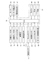
- FIG. 6B is a diagram illustrating a state when the drive switch that maintains the drive switch in the OFF state is not operated. It is an example of a change of the block diagram of the small electric vehicle.
- the small electric vehicle of the present embodiment is an electric tricycle that can fold the frame, performs self-running control that can start, accelerate, constant speed, and decelerate, and is mainly intended for healthy elderly people. is there.
- a part of the basic configuration may be omitted, and the dimensional ratios of the drawn parts are not necessarily accurate.
- the small electric vehicle 1 of the present embodiment includes a front frame 11, a handle shaft holder 13, and a rear frame 15.
- a handle shaft holder 13 is pivotally supported at the front end portion of the front frame 11 so as to be rotatable about the first rotation axis D1.
- a handle frame 17 is attached to the front end portion of the handle shaft holder 13 so as to be rotatable in a substantially horizontal direction.
- a handle 19 is fixed to the upper end portion of the handle frame 17.
- a wheel support frame 21 is fixed to the lower end portion of the handle frame 17.
- a front wheel 23 is rotatably supported on the wheel support frame 21.
- the seat post 25 is integrally connected to the rear end portion of the front frame 11.
- the upper portion of the seat post 25 has a cylindrical shape, and a seat support frame 27 is inserted into the cylindrical portion of the seat post 25 so as to be vertically movable.
- a seat 29 is fixed to the upper end portion of the seat support frame 27.
- the lock handle 31 is pivotally supported at the lower end of the seat post 25 so as to be rotatable about the second rotation axis D2.
- a lock lever 33 is provided in the lock handle 31.
- the rear frame 15 is pivotally supported at the rear end portion of the front frame 11 so as to be rotatable about the third rotation axis D3.
- a pair of rear wheels 35 are rotatably supported at the rear end portion of the rear frame 15 on both the left and right sides with respect to the front direction.
- a motor drive control unit 37 is attached to the lower surface of the rear frame 15.
- the front end portion of the first link lever 39 is pivotally supported below the rear portion of the handle shaft holder 13 so as to be rotatable about the fourth rotation axis D4.
- a front end portion of the second link lever 41 is pivotally supported at the rear end portion of the first link lever 39 so as to be rotatable about the fifth rotation axis D5.
- the rear end portion of the second link lever 41 is pivotally supported so that the front end portion of the rear frame 15 can rotate about the sixth rotation axis D6.
- a guide hole and a positioning groove 43 are provided at the rear part of the handle shaft holder 13.
- a positioning pin 45 is engaged with the guide hole and the positioning groove 43.
- the positioning pin 45 is provided at the front end of the front frame 11 and is connected to the lock lever 33 by an unillustrated inner cable.
- a pair of footrests 47 are provided at the rear part of the handle shaft holder 13 on both the left and right sides with respect to the front direction.
- the positioning pin 45 is fitted in a notch groove (hereinafter referred to as “lower notch groove”) provided below the guide hole and the positioning groove 43.
- lower notch groove a notch groove
- the lock lever 33 When switching from the unfolded state of FIG. 1 to the folded state of FIG. 2, the lock lever 33 is grasped and the lock lever 33 is pulled backward. Accordingly, the positioning pin 45 is separated from the guide hole and the lower notch groove of the positioning groove 43 via an inner cable (not shown), so that the front frame 11 is rotatable with respect to the handle shaft holder 13.
- the lock handle 31 is rotated upward away from the rear frame 15 about the second rotation axis D2.
- the claw portion 31A (see FIG. 2) of the lock handle 31 moves away from the second rotation axis D2. Therefore, the rear frame 15 connected to the second rotation axis D2 can rotate with respect to the front frame 11 with the sixth rotation axis D6 as an axis. Thereby, the small electric vehicle 1 of this embodiment can be folded.
- the lock handle 31, the handle frame 17, the handle 19 and the like are brought close to each other while the lock lever 33 is grasped, the rear weight of the front frame 11 via the seat post 25 is coupled with the weight of the small electric vehicle 1 of the present embodiment.
- the end rotates in a direction approaching the handle shaft holder 13.
- the positioning pin 45 of the front frame 11 is located in the guide hole that connects the notch groove (hereinafter referred to as “upper notch groove”) provided above the guide hole and the positioning groove 43 and the lower notch groove. ing. Therefore, the positioning pin 45 moves through the guide hole from the position of the lower notch groove of the guide hole and the positioning groove 43 to the position of the upper notch groove as the front frame 11 rotates. Further, as the front frame 11 rotates, the rear frame 15, the first link lever 39, and the second link lever 41 also rotate and move in a direction approaching the handle shaft holder 13 by the rotation shafts that are pivotally supported by each. .
- the positioning pin 45 of the front frame 11 comes into contact with the end surface of the guide hole and the positioning groove 43 on the upper notch groove side, and the rotation of the front frame 11 is suppressed.
- the lock lever 33 is released in a state where the rotation of the front frame 11 is suppressed, the positioning pin 45 of the front frame 11 is fitted into the guide hole and the upper notch groove of the positioning groove 43. Since the positioning pin 45 is held at this position by an urging force of a tension spring (not shown), the front frame 11 is locked at this folded position.
- the rear frame 15, the first link lever 39, and the second link lever 41 are also rotated in the direction closer to the handle shaft holder 13 by the rotation shafts pivotally supported on the respective frames.
- the small electric vehicle 1 of the present embodiment is in the folded state shown in FIG.
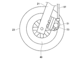
- a brake disc 49 is provided inside the front wheel 23.
- a front brake caliper 51 that constitutes a disc brake together with a brake disc 49 is fixed to the wheel support frame 21.
- the right inner cable 53 is attached to the front brake caliper 51.
- the right inner cable 53 is a drive source for the front brake caliper 51.
- the right inner cable 53 passes through the right outer cable 57.
- a brake disc 101 is provided inside the rear wheel 35.
- the rear frame 15 is provided with a rear wheel frame 15A that rotatably supports the rear wheel 35.
- a motor 85 for electrically driving the rear wheel 35 is fixed to the rear wheel frame 15A, and a rear brake caliper 103 that constitutes a disc brake together with the brake disc 101 is fixed.
- the left inner cable 105 is attached to the rear brake caliper 103.
- the left inner cable 105 is a drive source for the rear brake caliper 103.
- the left inner cable 105 passes through the left outer cable 109.
- the brake-related configuration described above may be provided in the left rear wheel 35 with respect to the front direction instead of the right rear wheel 35 with respect to the front direction.
- the handle 19 is a bar type similar to a bicycle.
- the handle 19 is provided with an ignition switch 59, a drive switch 61, a motor operation LED 63, a speed setting switch 65, and an abnormality display LED 67.
- the ignition switch 59 is a select type switch that is used when self-running control is executed.
- the drive switch 61 is a momentary push button switch used when the self-running control is executed. Accordingly, the drive switch 61 is maintained in an on state when the pressing operation is continued, and is maintained in an off state when the pressing operation is released.
- the motor operation LED 63 is a display device that is turned on, blinked, or turned off when the self-running control is executed.
- the speed setting switch 65 can switch the maximum speed during the self-running control to one of low speed, medium speed, and high speed.
- the maximum speed when switched to low speed is 2 km / h
- the maximum speed when switched to medium speed is 4 km / h
- the maximum speed when switched to high speed is 6 km / h. h.
- the abnormality display LED 67 is a display device that is turned on when an abnormality occurs when the self-running control is executed. Self-running control will be described later.
- a right brake lever 69 is attached to the handle 19 on the right side (right side with respect to the forward direction) in FIG. 5, and a left brake lever 71 is attached on the left side (left side with respect to the front direction) in FIG.
- the other end of the right outer cable 57 is connected to the right brake lever 69, and the other end of the right inner cable 53 (see FIG. 3) passing through the right outer cable 57 is attached. Yes.
- the right brake lever 69 is provided with a front wheel brake switch 55.
- the front wheel brake switch 55 is turned on when the stroke of the right inner cable 53 is to be detected and the stroke displacement of the right inner cable 53 is greater than or equal to the first predetermined distance.
- the front brake caliper 51 When the front wheel brake switch 55 is on, the front brake caliper 51 (see FIG. 3) operates. Therefore, when the brake is applied to the front wheel 23 (see FIG. 3), the driver holds the right brake lever 69 deeply, so that the right brake lever 69 is moved to the position indicated by reference numeral 69A or the right brake lever 69 is moved to the reference numeral. It is moved from the position indicated by 69A to the lower side (handle 19 side) in FIG.
- the other end of the left outer cable 109 is connected to the left brake lever 71, and the other end of the left inner cable 105 (see FIG. 4) passing through the left outer cable 109 is attached. Yes.
- the left brake lever 71 is provided with a rear wheel brake switch 73.
- the rear wheel brake switch 73 detects the stroke of the left inner cable 105, and turns on when the stroke displacement of the left inner cable 105 is greater than or equal to a second predetermined distance.
- the stroke displacement of the left inner cable 105 becomes equal to the second predetermined distance, and the rear wheel brake switch 73 is turned on. Even if the left brake lever 71 moves from the position indicated by reference numeral 71A to the lower side in FIG. 5 (the handle 19 side), the stroke displacement of the left inner cable 105 is greater than the second predetermined distance, so the rear wheel brake switch 73 Turns on.
- a seat sensor 77 is provided in the seat 29 provided at the upper end of the seat support frame 27.
- the seating sensor 77 detects the pressure acting on the seat 29, and turns on while detecting a pressure greater than a predetermined value.
- a pressure greater than a predetermined value acts on the seat 29, so the seating sensor 77 is turned on.
- the motor drive control unit 37 includes a CPU 79, a timer 80, a ROM 81, and a RAM 83.
- the CPU 79 is an arithmetic device and a control device that control the entire small electric vehicle 1 of the present embodiment.
- a timer 80, a ROM 81, and a RAM 83 are connected to the CPU 79.
- the timer 80 is a timing device that performs timing for executing control of the entire small electric vehicle 1 of the present embodiment.
- a built-in timer of the CPU 79 may be used, or software may be used.
- the ROM 81 stores various programs. For example, programs and speed curves (accelerated running / constant speed running / decelerated running curves) used in the self-running control are stored in the ROM 81.
- the RAM 83 temporarily stores data necessary for data processing by the CPU 79.
- the CPU 79 includes a front wheel brake switch 55, a rear wheel brake switch 73, an ignition switch 59, a drive switch 61, a speed setting switch 65, a seating sensor 77, an acceleration sensor 107, a gyro sensor 111, a motor rotation speed detection unit 86, a motor.
- An operation LED 63 and an abnormality display LED 67 are connected.
- the acceleration sensor 107 is a device that detects the acceleration of the small electric vehicle 1 of the present embodiment and is turned on while detecting the acceleration. For example, the acceleration sensor 107 is attached in the motor drive control unit 37.
- the gyro sensor 111 is a measuring device that detects an angle (posture) of the small electric vehicle 1 of the present embodiment, that is, an inclination angle with respect to the horizontal direction (hereinafter referred to as “inclination angle”), for example, a motor drive control unit. 37 is attached.
- the motor rotation number detection unit 86 is a measuring device that detects the rotation number of the motor 85, and is attached to the motor 85, for example. Specific examples of the motor rotation number detection unit 86 include a hall sensor and an encoder.
- a motor 85 is connected to the CPU 79.
- the motor 85 uses a battery (not shown) as a drive source and electrically drives the rear wheel 35 (see FIG. 4) on the right side with respect to the front direction.
- the motor 85 may be one that electrically drives both the rear wheels 35 or the front wheels 23.
- any one of the following conditions (1) to (5) is established while the drive switch 61 is on.
- the seating sensor 77 is turned off because the driver is not seated on the seat 29 or the like.
- the acceleration sensor 107 is turned on.
- the inclination angle detected by the gyro sensor 111 is outside the range of ⁇ 10 ° to + 10 °.
- the front wheel brake switch 55 is turned on.
- the drive switch 61 is switched from the OFF state to the ON state, and when the driver continues the pressing operation, the driving switch 61 is maintained in the ON state. Then, drive control of the motor 85 is started. Since the rear wheel 35 (see FIG. 4) is electrically driven by the drive control of the motor 85, the small electric vehicle 1 starts and accelerates uniformly until the self-running speed of the small electric vehicle 1 reaches the maximum speed. Driving is performed. When the self-running speed of the small electric vehicle 1 reaches the maximum speed, constant speed running is performed in which the small electric vehicle 1 self-runs at the maximum speed.
- the small electric vehicle 1 is uniformly accelerated from 0 km / h to 2 km / h and then 2 km. Drive at a constant speed at / h.
- the small electric vehicle 1 when the maximum speed is set to the medium speed by the speed setting switch 65 at the time of starting, the small electric vehicle 1 is uniformly from 0 km / h to 4 km / h. After accelerating, the vehicle runs at a constant speed of 4 km / h.
- the maximum speed is set to a high speed by the speed setting switch 65 at the time of starting, the small electric vehicle 1 is uniformly accelerated from 0 km / h to 6 km / h and then fixed at 6 km / h. Drive fast.
- the small electric vehicle 1 moves from 2 km / h to 4 km / h. After accelerating uniformly, run at a constant speed of 4 km / h.
- the maximum speed is switched from the medium speed to the high speed by the speed setting switch 65 during the self-running at the constant speed of 4 km / h
- the small electric vehicle 1 uniformly accelerated from 4 km / h to 6 km / h. Later, drive at a constant speed of 6 km / h.
- the small electric vehicle 1 is 2 km / h. To 6km / h, and then at a constant speed of 6km / h.
- the small electric vehicle 1 when the maximum speed is switched from the low speed to the medium speed by the speed setting switch 65 during acceleration traveling up to 2 km / h, the small electric vehicle 1 uniformly accelerates up to 4 km / h and then reaches 4 km / h. Drive at a constant speed.
- the maximum speed is switched from the medium speed to the high speed by the speed setting switch 65 during acceleration traveling up to 4 km / h, the small electric vehicle 1 uniformly accelerates up to 6 km / h and then is fixed at 6 km / h. Drive fast.
- the maximum speed of the small electric vehicle 1 is set to a high speed of 6 km / h by the speed setting switch 65. Note that the same traveling sequence is applicable even when the speed is set to 2 km / h at a low speed or 4 km / h at a medium speed.
- stage B1 the drive control of the motor 85 is performed, and the small electric vehicle 1 is traveling at a constant speed at the maximum speed (6 km / h).
- the driving switch 61 is switched from the on state to the off state, and when the driving switch 61 is maintained in the off state, the motor 85
- the small electric vehicle 1 is decelerated by the drive control.
- the decelerating traveling is uniformly decelerated until the self-running speed of the small electric vehicle 1 reaches a predetermined minimum speed (in this embodiment, a speed lower than the low speed of 2 km / h set by the speed setting switch 65). That is.
- a predetermined minimum speed in this embodiment, a speed lower than the low speed of 2 km / h set by the speed setting switch 65. That is.
- stage B2 when the self-running speed of the small electric vehicle 1 reaches the minimum speed, the power supply to the motor 85 is cut off, and the drive control of the motor 85 is stopped. In such a case, the motor 85 is in a free-running state where it continues to rotate by inertia, and the self-running speed of the small electric vehicle 1 becomes slower due to frictional resistance and the like.
- step B3 when the motor 85 is in a free-running state, the driver switches the drive switch 61 from the off state to the on state when the driver performs a pressing operation, and the driver switches the driving switch by continuing the pressing operation.
- the drive control of the motor 85 is resumed. Since the rear wheel 35 (see FIG. 4) is electrically driven by the drive control of the motor 85, the small electric vehicle 1 is accelerated again, and the self-running speed of the small electric vehicle 1 becomes the maximum speed (6 km / h). Acceleration running that accelerates uniformly is performed. When the self-running speed of the small electric vehicle 1 reaches the maximum speed (6 km / h), constant speed running is performed in which the small electric vehicle 1 self-runs at the maximum speed (6 km / h).
- the inclination angle detected by the gyro sensor 111 is ⁇ 10 ° even when the drive switch 61 is on, that is, the small electric vehicle 1 is accelerating or traveling at a constant speed. From the above, if it is outside the range of + 10 ° or less, the small electric vehicle 1 is decelerated. However, the range from ⁇ 10 ° to + 10 ° is an example, and the present invention is not limited to this.
- step B4 before the self-propelling speed of the small electric vehicle 1 reaches the minimum speed, the driver performs an operation of deeply grasping the right brake lever 69 or the left brake lever 71, whereby the front wheel brake switch 55 or the rear When the wheel brake switch 73 is turned on, the power supply to the motor 85 is cut off and the drive control of the motor 85 is stopped. In such a case, the motor 85 enters a free run state.
- the operation of the front brake caliper 51 or the rear brake caliper 103 is started. That is, during the ON operation of the front wheel brake switch 55, the front brake caliper 51 is activated by the gripping operation of the right brake lever 69, so that mechanical braking by the front brake caliper 51 can be applied to the front wheel 23. Alternatively, while the rear wheel brake switch 73 is on, the rear brake caliper 103 is actuated by the gripping operation of the left brake lever 71, so that mechanical braking by the rear brake caliper 103 can be applied to the rear wheel 35. .
- step B4 in FIG. 9 for convenience of description, the driver performs the operation of deeply grasping the right brake lever 69 and the left brake lever 71 simultaneously, so that the front wheel brake switch 55 and the rear wheel brake switch 73 are simultaneously turned on. Although the case where it becomes operation
- step B5 when the self-propelled speed of the small electric vehicle 1 reaches 0 km / h by mechanical braking of the front brake caliper 51 or the rear brake caliper 103 and the small electric vehicle 1 is stopped, the acceleration sensor 107 Turns off. Further, when the driver releases the finger from the right brake lever 69 or the left brake lever 71, the front wheel brake switch 55 or the rear wheel brake switch 73 is turned off. Furthermore, when the driver leaves the seat 29, the seating sensor 77 is turned off.
- the mechanical braking according to the present embodiment is performed by operating the front brake caliper 51 or the rear brake caliper 103 by the left and right outer cables 57 and 109 as described above.
- the operation of the front brake caliper 51 or the rear brake caliper 103 is performed by the wire, it may be operated by electricity or hydraulic pressure.
- step B5 in FIG. 9 the front wheel brake switch 55 and the rear wheel brake switch 73 are simultaneously turned off when the driver performs an operation to release his / her finger from the right brake lever 69 and the left brake lever 71 at the same time.
- operation ON operation
- the small electric vehicle 1 of this embodiment is started and accelerated by electric drive. ⁇ Can be driven at a constant speed. Thereafter, if the driver releases the pressing operation of the drive switch 61, the small electric vehicle 1 of the present embodiment can be decelerated to the minimum speed by electric drive. Furthermore, regardless of whether the drive switch 61 is pressed or not, if the driver who is electrically driven performs an operation of deeply grasping the right brake lever 69 or the left brake lever 71, the electric drive is stopped. The small electric vehicle 1 of this embodiment can be decelerated or stopped by mechanical braking. Note that the electric drive is also stopped when the small electric vehicle 1 of the present embodiment decelerates and the self-running speed becomes the minimum speed.
- the self-running control program is stored in the ROM 81 and is executed by the CPU 79.
- the CPU 79 starts execution of the self-running control program and determines whether or not the ignition switch 59 is turned on (S101).
- the CPU 79 determines again whether or not the ignition switch 59 is turned on (S101).
- the CPU 79 turns on the power supply (103).
- the CPU 79 confirms the abnormality of the CPU 79 itself (S105). If the CPU 79 itself has an abnormality (S107: YES), the CPU 79 turns on the abnormality display LED 67 (S109) and confirms the abnormality of the CPU 79 itself again (S105).
- the CPU 79 determines whether or not the ignition switch 59 is turned on (S111). At this time, if the abnormality display LED 67 is lit, the CPU 79 turns off the abnormality display LED 67.
- the CPU 79 determines whether or not the seating sensor 77 is turned on (S113).
- the CPU 79 determines again whether or not the ignition switch 59 is turned on (S111).
- the CPU 79 determines whether or not the front wheel brake switch 55 is turned off (S115).
- the CPU 79 determines again whether or not the ignition switch 59 is turned on (S111). Alternatively, when the front wheel brake switch 55 is turned off (S115: YES), the CPU 79 determines whether or not the rear wheel brake switch 73 is turned off (S117).
- the CPU 79 determines again whether or not the ignition switch 59 is on (S111). Alternatively, when the rear wheel brake switch 73 is turned off (S117: YES), the CPU 79 determines whether or not the motor rotation signal is off (S119). This determination is made based on the output signal of the motor rotation speed detection unit 86.
- the CPU 79 determines again whether or not the ignition switch 59 is on (S111). Alternatively, when the motor rotation signal is off (S119: YES), the CPU 79 determines whether or not the acceleration sensor 107 is turned off (S121).
- the CPU 79 determines again whether or not the ignition switch 59 is turned on (S111). Alternatively, when the acceleration sensor 107 is turned off (S121: YES), the CPU 79 determines whether or not the tilt angle detected by the gyro sensor 111 is within a range of ⁇ 10 ° to + 10 °. (S123).
- the CPU 79 again determines whether or not the ignition switch 59 is turned on. It is determined (S111).
- the CPU 79 determines whether or not the drive switch 61 is in an ON state. (S125).
- the CPU 79 determines again whether or not the ignition switch 59 is on (S111). Alternatively, when the drive switch 61 is in the on state (S125: YES), the CPU 79 performs a motor acceleration process as shown in FIG. 11 (S127).
- the CPU 79 performs driving of the small electric vehicle 1 by performing drive control of the motor 85 based on the speed curve (acceleration curve) stored in the ROM 81. At this time, if the small electric vehicle 1 is stopped, the small electric vehicle 1 is started.
- the CPU 79 turns on the motor operation LED 63 (S129) and performs a detection process (S131).
- the CPU 79 determines whether or not the ignition switch 59 is turned on (S1001).
- the CPU 79 performs the process of S701 described in FIG.
- the CPU 79 determines whether or not the seating sensor 77 is turned on (S1003).
- the CPU 79 determines whether or not the front wheel brake switch 55 is turned off (S1005).
- the CPU 79 determines whether or not the rear wheel brake switch 73 is turned off (S1007).
- the CPU 79 determines whether or not the inclination angle detected by the gyro sensor 111 is within a range from ⁇ 10 ° to + 10 °. Is discriminated (S1009).
- the CPU 79 determines whether or not the drive switch 61 is in the ON state. (S1011).
- the CPU 79 when the drive switch 61 is in the OFF state (S1011: NO), the CPU 79 performs the process of S401 described in FIG. Alternatively, when the drive switch 61 is in the on state (S1011: YES), as shown in FIG. 11, the CPU 79 confirms the number of rotations of the motor 85 (S133). This confirmation is performed based on the output signal of the motor rotation speed detector 86.
- the CPU 79 determines whether or not the rotational speed of the motor 85 is less than the set rotational speed (S135).
- the set rotational speed is the rotational speed of the motor 85 corresponding to the speed set by the speed setting switch 65 and is stored in the ROM 81.
- the speed setting switch 65 is set to a low speed (2 km / h)
- the rotational speed of the motor 85 is 708 rpm.
- the medium speed (4 km / h) is set
- the rotational speed of the motor 85 is 1416 rpm.
- the rotational speed of the motor 85 is 2123 rpm. Note that these rotational speeds are determined by the reduction ratio of the motor 85 and the diameter of the driving wheel (in this embodiment, the rear wheel 35), and are not limited to these numerical values.
- the CPU 79 performs the detection process again (S131).
- the rotational speed of the motor 85 is equal to or higher than the set rotational speed (S135: YES), that is, when the self-running speed of the small electric vehicle 1 is higher than the speed set by the speed setting switch 65.
- the CPU 79 performs a constant motor speed process (S201).
- the CPU 79 controls the drive of the motor 85 based on the speed curve (constant speed curve) stored in the ROM 81, thereby setting the speed set by the speed setting switch 65 as the free-running speed.
- the small electric vehicle 1 travels at a constant speed.
- the CPU 79 performs detection processing (S203).
- This detection process (S203) is the same as the detection process shown in FIG. Therefore, when the drive switch 61 is in the ON state (S1011: YES), as shown in FIG. 13, the CPU 79 confirms the rotation speed of the motor 85 (S205).
- the CPU 79 determines whether or not the difference between the rotational speed of the motor 85 and the set rotational speed is within a range from ⁇ 10% to + 10% of the set rotational speed.
- the CPU 79 performs the detection process again. (S203).
- the difference between the rotational speed of the motor 85 and the set rotational speed is outside the range of ⁇ 10% or more to + 10% or less of the set rotational speed (S207: NO), as shown in FIG.
- the motor reacceleration process is performed (S301).
- the CPU 79 performs the accelerated running of the small electric vehicle 1 by controlling the driving of the motor 85 based on the speed curve (acceleration curve) stored in the ROM 81. According to the flowcharts shown in FIGS. 10 to 18, the motor reacceleration process is not performed when the small electric vehicle 1 is stopped.
- the CPU 79 turns on the motor operation LED 63 (S303) and performs a detection process (S305).
- This detection process (S305) is the same as the detection process shown in FIG. Therefore, when the drive switch 61 is in the ON state (S1011: YES), as shown in FIG. 14, the CPU 79 confirms the rotation speed of the motor 85 (S307).
- the CPU 79 determines whether or not the rotation speed of the motor 85 is less than the set rotation speed (S309).
- the rotation speed of the motor 85 is less than the set rotation speed (S309: YES), that is, when the self-running speed of the small electric vehicle 1 is slower than the speed set by the speed setting switch 65.
- the CPU 79 performs the detection process again (S305).
- the rotational speed of the motor 85 is equal to or higher than the set rotational speed (S309: NO), that is, when the self-running speed of the small electric vehicle 1 is higher than the speed set by the speed setting switch 65, As shown in FIG. 14, the CPU 79 performs the constant motor speed process shown in FIG. 13 described above (S201).
- the CPU 79 decelerates the small electric vehicle 1 by, for example, controlling the driving of the motor 85 based on the speed curve (deceleration curve) stored in the ROM 81.
- electric braking such as regenerative braking or interphase short-circuiting may be performed.
- the CPU 79 blinks the motor operation LED 63 (S403), and determines whether or not the ignition switch 59 is turned on (S405).
- the CPU 79 determines whether or not the front wheel brake switch 55 is off (S407).
- the CPU 79 determines whether or not the rear wheel brake switch 73 is turned off (S409).
- the CPU 79 when the drive switch 61 is in the ON state (S411: NO), the CPU 79 performs the motor reacceleration process shown in FIG. 14 described above (S301). Alternatively, when the drive switch 61 is in the OFF state (S411: YES), the CPU 79 confirms the rotation speed of the motor 85 (S413).
- the CPU 79 determines whether or not the rotation speed of the motor 85 is equal to or less than the set rotation speed (S415).
- the set rotation speed in S415 is different from the set rotation speeds so far (S135, S207, S309), and is set by the minimum speed stored in advance in the ROM 81 (in this embodiment, the speed setting switch 65).
- the number of rotations of the motor 85 corresponding to the low speed (slower than 2 km / h).
- the CPU 79 sets the ignition switch 59. It is determined again whether or not is turned on (S405).
- the rotational speed of the motor 85 is equal to or lower than the set rotational speed (S415: YES), that is, when the self-propelled speed of the small electric vehicle 1 is slower than the minimum speed
- the CPU 79 returns to FIG. As shown, motor stop processing is performed (S501).
- the CPU 79 puts the motor 85 into a free-run state by disconnecting the motor 85 from a battery power supply line (not shown). As described above, the CPU 79 determines that the front wheel brake switch 55 is turned on when the front wheel brake switch 55 is turned on (S1005: NO), and the rear wheel brake switch 73 is turned on (S1007: NO). The motor stop process is also performed when the on-operation is performed (S407: NO) or when the rear wheel brake switch 73 is turned on (S409: NO).
- the CPU 79 turns off the motor operation LED 63 (S503), and determines whether or not the ignition switch 59 is turned on (S505).
- the CPU 79 determines whether or not the seating sensor 77 is turned on (S507).
- the CPU 79 again determines whether or not the processing of S111 described in FIG. 10, that is, the ignition switch 59 is turned on. It is determined (S111).
- the CPU 79 determines whether or not the front wheel brake switch 55 is on (S509).
- the CPU 79 determines whether or not the process of S111 described in FIG. 10, that is, the ignition switch 59 is turned on. The determination is made again (S111).
- the CPU 79 determines whether or not the rear wheel brake switch 73 is on (S511).
- the CPU 79 determines whether or not the process of S111 described in FIG. 10, that is, the ignition switch 59 is turned on. Is discriminated again (S111).
- the CPU 79 determines whether or not the acceleration sensor 107 is turned on (S513).
- the CPU 79 again determines whether or not the processing of S111 described in FIG. 10, that is, the ignition switch 59 is turned on. It is determined (S111).
- the CPU 79 determines again whether or not the processing of S505 described in FIG. 16, that is, the ignition switch 59 is turned on. (S505).
- the CPU 79 starts measuring time using the timer 80.
- the CPU 79 determines whether or not the duration time of the off operation of the seating sensor 77 is equal to or longer than the timer set time (S603). In this determination, the time measurement result by the timer 80 in S601 described above is used. The timer set time is stored in advance in the ROM 81.
- the CPU 79 assumes that the driver is seated on the seat 29 and is described in FIG. A detection process (S131) is performed.
- the CPU 79 determines that the driver is away from the seat 29, and the motor deceleration process (FIG. S401) is performed.
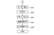
- the CPU 79 performs the motor stop process shown in FIG. 18 as described above. This is performed (S701).
- the motor stop process is the same as the motor stop process (S501) described in FIG.
- the CPU 79 turns off the LEDs such as the motor operation LED 63 (S703), and resets the memory such as the RAM 83 (S705). Further, the CPU 79 turns off the power supply (S707), sets the CPU 79 itself in the standby mode, and terminates the execution of the self-running control program.
- the small electric vehicle 1 of the present embodiment By performing drive control of the motor 85 according to such a situation (S127, S201), the small electric vehicle 1 of the present embodiment performs acceleration traveling to the set speed of the speed setting switch 65, and then Constant speed running is performed with the speed set by the speed setting switch 65 as the self-running speed.
- the driver can cause the small electric vehicle 1 to perform acceleration traveling or constant speed traveling only by pressing the drive switch 61. Therefore, the small electric vehicle 1 of the present embodiment does not give the driver a feeling of fatigue during the self-propelled operation.
- acceleration driving or constant speed driving according to the driver's intention can be performed by pressing the drive switch 61 and releasing the fingers from the left and right brake levers 69 and 71.
- a self-propelled driver may perform an operation of deeply grasping the right brake lever 69 or the left brake lever 71.
- the stroke amount of the right brake lever 69 is Is greater than or equal to the first predetermined distance (S1005: NO, S407: NO).
- the left brake lever 71 is located on the lower side (handle 19 side) in FIG. 5 from the position indicated by reference numeral 71A or the position indicated by reference numeral 71A, the stroke amount of the left brake lever 71 is the second predetermined distance. This is the above (S1007: NO, S409: NO).
- the small electric vehicle 1 of the present embodiment mechanical braking is performed by the right brake lever 69 or the left brake lever 71 (S509: YES, S511: YES). Therefore, regardless of whether the drive switch 61 is pressed or not, the small electric vehicle 1 can be decelerated or stopped by the grasping operation of the left and right brake levers 69 and 71, which have been used to date. Sex is secured.
- the driver can cause the small electric vehicle 1 to decelerate by merely releasing the pressing operation of the drive switch 61 without operating the left and right brake levers 69 and 71. Therefore, in the small electric vehicle 1 according to the present embodiment, by depressing the pressing operation of the drive switch 61, the vehicle can be decelerated according to the driver's intention without sudden stop.
- the motor 85 is in a free-run state by cutting off the power supply in response to the deceleration to the minimum speed (S415: YES, S501). Therefore, when the self-propelled speed of the small electric vehicle 1 is less than the minimum speed, the small electric vehicle 1 is decelerated or stopped without sudden stop by the grasping operation of the left and right brake levers 69 and 71, which have been familiar to date. It can be stopped. *
- the drive switch 61 is provided adjacent to the right brake lever 69.
- the driver presses the drive switch 61 with his / her thumb as shown in FIG.
- the four fingers other than the thumb are holding the grip 113 provided on the handle 19 and are separated from the right brake lever 69, for example.
- the driver performs an operation of grasping the right brake lever 69, for example, as shown in FIG. 19B, the driver holds the grip 113 with the thumb and the right brake lever with four fingers other than the thumb. grab 69.
- the drive switch 61 is provided around the right brake lever 69, and the right brake lever 69 and the drive switch 61 are easily switched as the operation target of the driver. Therefore, the operability can be further improved. Further, since the drive switch 61 is provided adjacent to the right brake lever 69, if the driver is accustomed to the operation of the bicycle, the driver cannot operate the drive switch 61 at the same time as operating the right brake lever 69. difficult. Although not shown, the same applies to the case where the drive switch 61 is provided around the left brake lever 71.
- the motor 85 when the motor stop process (S501) is performed in the self-running control program, the motor 85 is in a free-run state (inertia), for example, by a technique that cuts off power supply from the inverter. Rotation). That is, when the self-running by the motor 85 is completed, the rear wheel 35 driven by the motor 85 can be freely rotated. Therefore, in the small electric vehicle 1 according to the present embodiment, when the self-propelling by the motor 85 is finished, the front wheel 23 and the pair of rear wheels 35 can be freely rotated so that they can be moved in an emergency or a folded state. Is easy.
- the right brake lever 69 is an example of a “brake lever”.
- the lever operation amount when the right brake lever 69 is at the position indicated by reference numeral 69A is an example of “predetermined operation amount”.
- the left brake lever 71 is an example of a “brake lever”.
- the lever operation amount when the left brake lever 71 is at the position indicated by reference numeral 71A is an example of “predetermined operation amount”. 2 km / h, which is the maximum speed when switched to low speed with the speed setting switch 65, 4 km / h, which is the maximum speed when switched to medium speed, or 6 km /, which is the maximum speed when switched to high speed h is an example of “first predetermined speed”.
- the preset minimum speed (in this embodiment, a speed lower than 2 km / h, which is a low speed set by the speed setting switch 65) is an example of a “second predetermined speed”.
- the range where the tilt angle is ⁇ 10 ° or more and + 10 ° or less is an example of “predetermined range”.
- the seat 29 is an example of a “seat”.
- a tape switch 115 as shown in FIG. 20 may be used instead of the push button type drive switch 61.
- the tape switch 115 is provided in the grip 113 provided on the handle 19 so as to face the right brake lever 69.
- the driver performs an operation to turn on the tape switch 115, for example, as shown in FIG. 20A, the driver grips the grip 113 with the thumb and tapes the grip 113 with four fingers other than the thumb. Grasp through switch 115. As a result, the driver can press the tape switch 115 without placing his thumb.
- the driver when the driver performs an operation of grasping the right brake lever 69, for example, as shown in FIG. 19B, the driver holds the grip 113 with the thumb and the right brake lever with four fingers other than the thumb. Grab 69.
- the tape switch 115 may be provided around the left brake lever 71.
- a push button type drive switch 117 of the same type as shown in FIG. 21 may be used instead of the momentary type push button type drive switch 61.
- the drive switch 117 is provided on the grip 113 provided on the handle 19 so as to face the ground, that is, on the back side of the paper surface of FIG.
- the driver performs an operation of depressing the drive switch 117, for example, as shown in FIG. 21A
- the driver holds the grip 113 with the thumb and uses the tip of four fingers other than the thumb to drive the drive switch 117. Press.
- the driver performs an operation of grasping the right brake lever 69 for example, as shown in FIG. 21B
- the driver holds the grip 113 with the thumb and the right brake lever with four fingers other than the thumb. Grab 69.
- the drive switch 117 may be provided around the left brake lever 71.
- an alternate drive switch may be used.
- the small electric vehicle 1 of the present embodiment may include a delay timer 119 between the seating sensor 77 and the CPU 79.
- the delay timer 119 invalidates the signal indicating that the duration time of the operation in which it is determined that the driver is away from the seat 29 is less than the predetermined time for the output signal of the seating sensor 77. Therefore, for example, when chattering occurs in the output signal of the seating sensor 77 because the driver sitting on the seat 29 floats for a moment or the small electric vehicle 1 vibrates, the output of the seating sensor 77 is output.
- the inability to proceed with the self-running control program based on the signal can be prevented (S113: NO). Thereby, operability is improved.
- the delay timer 119 is an example of a “false detection prevention unit”.
- the small electric vehicle 1 of the present embodiment may include a sensor for finding a forward obstacle.
- the sensor is a leather sensor, an ultrasonic sensor, a camera sensor, or the like, and is attached to a location that does not block the front direction. Thereby, safety is improved.
- the self-propelling control program may be executed using only the front wheel brake switch 55, or the self-propelling control program may be executed using only the rear wheel brake switch 73. . *
- braking by manual operation of the left and right brake levers 69 and 71 is performed via the left and right outer cables 57 and 109, but may be performed via the hydraulic pressure of the brake fluid. Further, the front brake caliper 51 and the rear brake caliper 103 may be replaced with a drum brake or the like.
- a brake pedal may be provided in place of the left and right brake levers 69 and 71.
- the small electric vehicle 1 of the present embodiment may include a speed sensor for measuring the speed.
- the speed measured by the speed sensor is used in place of the rotational speed of the motor 85 during the execution of the self-running control program (S133, S135, S205, S207, S307, S309, S413, S415).
- the small electric vehicle 1 of the present embodiment may include a setting switch for switching the minimum speed on the handle 19 or the like. With this setting switch, the minimum speed during the self-running control may be switched to one of low speed, medium speed, and high speed.
- the minimum speed may be 0 km / h.
- the maximum speed during the self-running control when the speed setting switch 65 is switched to a high speed is 6 km / h, but it may be faster than 6 km / h.
Landscapes
- Engineering & Computer Science (AREA)
- Mechanical Engineering (AREA)
- Power Engineering (AREA)
- Transportation (AREA)
- Automatic Cycles, And Cycles In General (AREA)
- Electric Propulsion And Braking For Vehicles (AREA)
Abstract
操作性及び安全性の向上を図った小型電動車両を提供すること。 段階A2では、駆動スイッチがオフ状態中において、下記の全ての状態が成立している。運転者がシートに着座し、着座センサーがオン動作になっている。小型電動車両が静止し、加速度センサーがオフ動作になっている。小型電動車両の傾斜が小さく、ジャイロセンサーで検出した傾斜角度が-10°以上から+10°以下の範囲内にある。運転者によって右ブレーキレバーから指を離す操作等が行われ、前輪ブレーキスイッチがオフ動作になっている。運転者によって左ブレーキレバーから指を離す操作等が行われ、後輪ブレーキスイッチがオフ動作になっている。このような場合において、運転者が押下操作を行うことにより駆動スイッチがオフ状態からオン状態に切り替えられると共に駆動スイッチのオン状態が維持されると、モーターの駆動制御が開始される。
Description
本発明は、自走可能な小型電動車両に関するものである。
従来より、自走可能な小型電動車両に関する技術が種々提案されている。例えば、下記特許文献1に記載された電動三輪車では、アクセルレバーが、操向ハンドル側から操縦者の手の指で操作するように設けられている。
アクセルレバーは、コントロールボックスに立設した支持片に、支軸を介して前後方向に回動するように支持され、支軸の支持位置にはリターンスプリングが巻装されていて、アクセルレバーに復帰習性を与えている。このアクセルレバーの先端部には円弧状の噛合い歯が形成されていて、車両走行用モータの回転を制御する可変抵抗器の外周に形成された噛合い歯と噛合っており、噛合い歯により可変抵抗器を回動させて車両の走行スピードをコントロールするようになっている。そして、アクセルレバーは、「0」位置にあるとき車両は走行を停止しており、この位置で操縦者の手の指で押し下げるか握るかして押圧すると車両は走行を開始し、アクセルレバーをさらに押圧するとスピードが次第に増して、「max」位置で最高速度の6km/hに達するようになっている。
アクセルレバーにおいては、上記「max」位置から、操縦者がさらに強い力でアクセルレバーを押し下げるか握るかして、所定圧以上の圧力で押圧して「非常停止」位置に達したときのみアクセルレバーの先端部と接触し、作動状態となるプランジャを設けると共に、このプランジャが作動したときにアクセルレバーの先端部と接触して作動し、車両走行用モータの電気回路を遮断するようにしたリミットスイッチを設けている。
電動三輪車が走行中に、操縦者が危険を感じて車両の走行を停止させなければならないときは、気持ちが動転して通常のアクセルレバー操作力よりはるかに大きい圧力でアクセルレバーを握ったり、押し下げてしまうことがある。このような場合には、アクセルレバーが上記「非常停止」位置まで回動し、プランジャを押圧して作動状態にすると共に、リミットスイッチを作動状態にする。その結果、車両走行用モータの電気回路が遮断されて車両は急停車し、危険を回避することができる。
しかしながら、操縦者は、その手で操向ハンドルを握ると共に、操向ハンドルから延ばした指でアクセルレバーを押圧し、上記「0」位置と上記「max」位置との間でアクセルレバーを押下することにより、電動三輪車のスピードを調整している。従って、電動三輪車が走行中の操縦者は、アクセルレバーを押下しながら操向ハンドルを握り込み続ける操作を常に行っているので、握力消耗等による負担が大きく、操作性に難を感じることがあった。
また、上記「max」位置と上記「非常停止」位置とは隣接している。従って、操縦者が通常のアクセルレバー操作力よりはるかに大きい圧力でアクセルレバーを握ったり、押し下げてしまう場合には、電動三輪車が最高速度又は急加速の状態から急停車するので、操縦者が感じた危険を回避することができても、急停車による衝撃を操縦者が受ける等、安全性を損なう虞があった。
そこで、本発明は、上述した点を鑑みてなされたものであり、操作性及び安全性の向上を図った小型電動車両を提供することを課題とする。
この課題を解決するためになされた請求項1に記載の小型電動車両は、非操作時にオフ状態を維持し操作時にオン状態を維持して自走を指令する駆動スイッチと、ブレーキレバーと、駆動スイッチの自走の指令に応じて駆動するモーターとを備え、モーターは、駆動スイッチがオン状態に維持され、且つ、ブレーキレバーのレバー操作量が所定操作量未満であることに応じて、第1所定速度まで加速走行したのち第1所定速度で定速走行する駆動制御を行い、ブレーキレバーは、レバー操作量が所定操作量以上になることに応じて、機械的制動を行うことを特徴とする。
請求項2に記載の小型電動車両は、請求項1に記載の小型電動車両であって、ブレーキレバーは、機械的制動を行う際に、モーターへの電力供給を遮断してモーターをフリーラン状態にすることを特徴とする。
ここで、フリーラン状態とは、回転中のモーターに対する電力供給が遮断されることによって、モーターが惰性で回転し続ける状態をいう。
請求項3に記載の小型電動車両は、請求項1又は請求項2に記載の小型電動車両であって、ブレーキレバーのレバー操作量が所定操作量未満である場合において、駆動スイッチがオフ状態では、モーターは、第2所定速度まで減速走行する駆動制御を行うことを特徴とする。
請求項4に記載の小型電動車両は、請求項3に記載の小型電動車両であって、モーターは、第2所定速度まで減速することに応じて、電力供給が遮断されてフリーラン状態になることを特徴とする。
請求項5に記載の小型電動車両は、請求項1乃至請求項4のいずれか一つに記載の小型電動車両であって、車両の水平方向に対する傾き角度を検出するジャイロセンサーを備え、ジャイロセンサーにより傾き角度が所定範囲外であると検出される場合に、発進時にあっては、モーターの駆動が禁止され、自走時にあっては、モーターは、第2所定速度まで減速走行する駆動制御を行うことを特徴とする。
請求項6に記載の小型電動車両は、請求項1乃至請求項5のいずれか一つに記載の小型電動車両であって、駆動スイッチは、ブレーキレバーの周辺に設けられることを特徴とする。
請求項7に記載の小型電動車両は、請求項1乃至請求項6のいずれか一つに記載の小型電動車両であって、座席に取り付けられた着座センサーを備え、着座センサーの出力信号に基づいて運転者が座席から離れていると判別される場合にモーターの駆動は禁止されることを特徴とする。
請求項8に記載の小型電動車両は、請求項7に記載の小型電動車両であって、着座センサーの出力信号について、1つの状態の継続時間が所定時間未満であることを示す信号を無効とする誤検知防止部を備えることを特徴とする。
請求項1に記載の小型電動車両は、駆動スイッチがオン状態に維持され、且つ、ブレーキレバーのレバー操作量が所定操作量未満であることに応じて、モーターによる駆動制御により、第1所定速度まで加速走行したのち第1所定速度で定速走行する。つまり、運転者は、駆動スイッチを操作するだけで、当該小型電動車両を加速走行又は定速走行させことができる。よって、請求項1に記載の小型電動車両は、自走操作中の運転者に疲労感を与えることがない。
さらに、請求項1に記載の小型電動車両では、ブレーキレバーのレバー操作量が所定操作量以上になることに応じて、ブレーキレバーによる機械的制動が行われる。よって、駆動スイッチの操作時及び非操作時に関係なく、今まで慣れ親しんだブレーキレバーの握込操作により、減速又は停車させることができるので、安全性が確保される。
以上より、請求項1に記載の小型電動車両では、操作性及び安全性が向上する。また、駆動スイッチの操作及びブレーキレバーの操作によって、運転者の意思に合わせた加速走行又は定速走行が行える。
請求項2に記載の小型電動車両では、ブレーキレバーによる機械的制動が行われる際に、モーターへの電力供給が遮断されてモーターがフリーラン状態になる。よって、機械的制動が効率的に行われる。
請求項3に記載の小型電動車両では、ブレーキレバーのレバー操作量が所定操作量未満である場合において、駆動スイッチがオフ状態では、モーターによる駆動制御により、第2所定速度まで減速走行する。つまり、運転者は、ブレーキレバーを操作することなく、駆動スイッチをオン状態からオフ状態に切り替える(駆動スイッチの非操作)だけで、当該小型電動車両を減速走行させことができる。よって、請求項3に記載の小型電動車両では、駆動スイッチの非操作によって、急停止することなく、運転者の意思に合わせた減速走行が行える。
請求項4に記載の小型電動車両では、モーターは、第2所定速度まで減速することに応じて、電力供給が遮断されてフリーラン状態になる。よって、当該小型電動車両の自走速度が第2所定速度未満である場合には、今まで慣れ親しんだブレーキレバーの握込操作によって、急停止することなく、減速又は停車させることができる。
請求項5に記載の小型電動車両では、ジャイロセンサーにより傾き角度が所定範囲外であると検出される場合に、発進時にあっては、モーターの駆動が禁止され、自走時にあっては、モーターによる駆動制御により、第2所定速度まで減速走行する。よって、発進時又は自走時の安定条件として、車両の水平方向に対する傾き角度を利用することが可能である。
請求項6に記載の小型電動車両では、ブレーキレバーの周辺に駆動スイッチが設けられており、ブレーキレバーと駆動スイッチとを運転者の操作対象として容易に切り替えることができるので、操作性をより向上させることが可能である。
請求項7に記載の小型電動車両では、着座センサーの出力信号に基づいて運転者が座席から離れていると判別される場合にモーターの駆動は禁止される。よって、座席に運転者が着座していない状態でモーターの駆動が実行されることを防止できる。
請求項8に記載の小型電動車両では、誤検知防止部は、着座センサーの出力信号について、1つの状態の継続時間が所定時間未満であることを示す信号を無効とする。よって、例えば、座席に着座している運転者が腰を一瞬浮かしたり、車両が振動すること等により、着座センサーの出力信号にチャタリングが発生した場合において、着座センサーの出力信号に基づくモーターの駆動禁止を防止することができる。
[1.小型電動車両の概要]
以下、本発明に係る小型電動車両について、具体化した本実施形態に基づき、図面を参照しつつ説明する。本実施形態の小型電動車両は、フレームを折り畳むことが可能であり、発進・加速・定速・減速走行が可能な自走制御を実行し、主に健常な高齢者を対象とする電動三輪車である。尚、以下の説明に用いる各図面では、基本的構成の一部が省略されて描かれていることがあり、描かれた各部の寸法比等は必ずしも正確ではない。
以下、本発明に係る小型電動車両について、具体化した本実施形態に基づき、図面を参照しつつ説明する。本実施形態の小型電動車両は、フレームを折り畳むことが可能であり、発進・加速・定速・減速走行が可能な自走制御を実行し、主に健常な高齢者を対象とする電動三輪車である。尚、以下の説明に用いる各図面では、基本的構成の一部が省略されて描かれていることがあり、描かれた各部の寸法比等は必ずしも正確ではない。
図1や図2に表すように、本実施形態の小型電動車両1は、フロントフレーム11、ハンドルシャフトホルダー13、及びリアフレーム15を備えている。フロントフレーム11の前端部には、ハンドルシャフトホルダー13が第1回動軸D1を軸心として回動可能に軸支されている。
ハンドルシャフトホルダー13の前端部には、ハンドルフレーム17が略水平方向に回動可能に取り付けられている。ハンドルフレーム17の上端部には、ハンドル19が固設されている。一方、ハンドルフレーム17の下端部には、車輪支持フレーム21が固着されている。車輪支持フレーム21には、前輪23が回動可能に支持されている。
フロントフレーム11の後端部には、シートポスト25が一体に連結されている。シートポスト25の上部は筒状になっており、シート支持フレーム27がシートポスト25の筒部に上下移動可能に挿着されている。シート支持フレーム27の上端部には、シート29が固設されている。
シートポスト25の下端部には、ロックハンドル31が第2回動軸D2を軸心として回動可能に軸支されている。ロックハンドル31内には、ロックレバー33が設けられている。
フロントフレーム11の後端部には、リアフレーム15が第3回動軸D3を軸心として回動可能に軸支されている。リアフレーム15の後端部には、前方向に対する左右の両側において、一対の後輪35が回動可能に支持されている。リアフレーム15の下面には、モーター駆動制御ユニット37が取り付けられている。
ハンドルシャフトホルダー13の後部下方には、第1リンクレバー39の前端部が第4回動軸D4を軸心として回動可能に軸支されている。第1リンクレバー39の後端部には、第2リンクレバー41の前端部が第5回動軸D5を軸心として回動可能に軸支されている。第2リンクレバー41の後端部は、リアフレーム15の前端部が第6回動軸D6を軸心として回動可能に軸支されている。
ハンドルシャフトホルダー13の後部には、誘導孔および位置決め溝43が設けられている。誘導孔および位置決め溝43には、位置決めピン45が係合している。位置決めピン45は、フロントフレーム11の前端部に設けられ、不図示のインナーケーブルでロックレバー33に接続されている。さらに、ハンドルシャフトホルダー13の後部には、前方向に対する左右の両側において、一対のフットレスト47が設けられている。
本実施形態の小型電動車両1では、図1に表すように、位置決めピン45が誘導孔および位置決め溝43の下側に設けられた切欠溝(以下、「下側切欠溝」という。)に嵌合されることにより、展開状態が保持(ロック)されている。
図1の展開状態から図2の折畳状態に切換える際は、ロックレバー33を掴んで、ロックレバー33を後方に引張する。これにより、位置決めピン45が、不図示のインナーケーブルを介して、誘導孔および位置決め溝43の下側切欠溝から離間して、フロントフレーム11がハンドルシャフトホルダー13に対して回動自在になる。
次に、ロックレバー33を掴んだ状態でロックハンドル31を、第2回動軸D2を回動中心にリアフレーム15から離間する上方に回動させる。ロックハンドル31が上方に回動すると、ロックハンドル31の爪部31A(図2参照)が第2回動軸D2から離れる。よって、第2回動軸D2に接続されているリアフレーム15は、第6回動軸D6を軸心とするフロントフレーム11に対する回動が可能になる。これにより、本実施形態の小型電動車両1は、折畳可能になる。
ロックレバー33を掴んだ状態でロックハンドル31とハンドルフレーム17、ハンドル19等とを近づけるようにすると、本実施形態の小型電動車両1の自重とも相まって、シートポスト25を介してフロントフレーム11の後端部がハンドルシャフトホルダー13に近づく方向に回動する。
この状態では、フロントフレーム11の位置決めピン45が、誘導孔および位置決め溝43の上側に設けられた切欠溝(以下、「上側切欠溝」という。)と下側切欠溝を繋ぐ誘導孔に位置している。従って、位置決めピン45はフロントフレーム11の回動に伴い、誘導孔および位置決め溝43の下側切欠溝の位置から上側切欠溝の位置へ誘導孔を通って移動する。さらに、フロントフレーム11の回動により、リアフレーム15、第1リンクレバー39、及び第2リンクレバー41も、それぞれに軸支された回動軸によりハンドルシャフトホルダー13に近づく方向に回動移動する。
さらに回動すると、フロントフレーム11の位置決めピン45が誘導孔および位置決め溝43の上側切欠溝側の端面に当接し、フロントフレーム11の回動が抑止される。フロントフレーム11の回動が抑止された状態で、ロックレバー33を放すと、フロントフレーム11の位置決めピン45が誘導孔および位置決め溝43の上側切欠溝に嵌合される。位置決めピン45は、不図示の引っ張りバネの付勢力によりこの位置に保持されているため、フロントフレーム11がこの折畳状態の位置でロックされる。フロントフレーム11の回動により、リアフレーム15、第1リンクレバー39、及び第2リンクレバー41も、それぞれに軸支された回動軸により、さらにハンドルシャフトホルダー13に近づく方向に回動するため、本実施形態の小型電動車両1は図2に表す折畳状態になる。
尚、本実施形態の小型電動車両1では、折畳状態から展開状態に切換える場合は、上記と逆に手順で操作する。
次に、前輪23が備えるブレーキ関係の構成について説明する。図3に表すように、前輪23の内側には、ブレーキディスク49が設けられている。車輪支持フレーム21には、ブレーキディスク49と共にディスクブレーキを構成するフロント用ブレーキキャリパー51が固定されている。
フロント用ブレーキキャリパー51には、右インナーケーブル53の一端部が取り付けられている。右インナーケーブル53は、フロント用ブレーキキャリパー51の駆動源である。また、右インナーケーブル53は、右アウターケーブル57の中を通っている。
次に、前方向に対する右側の後輪35が備えるブレーキ関係の構成について説明する。図4に表すように、後輪35の内側には、ブレーキディスク101が設けられている。リアフレーム15には、後輪35を回動可能に支持する後輪フレーム15Aが設けられている。後輪フレーム15Aには、後輪35を電動駆動させるためのモーター85が固定され、ブレーキディスク101と共にディスクブレーキを構成するリア用ブレーキキャリパー103が固定されている。
リア用ブレーキキャリパー103には、左インナーケーブル105の一端部が取り付けられている。左インナーケーブル105は、リア用ブレーキキャリパー103の駆動源である。また、左インナーケーブル105は、左アウターケーブル109の中を通っている。
尚、上述したブレーキ関係の構成は、前方向に対する右側の後輪35に代え、前方向に対する左側の後輪35に備えてもよい。
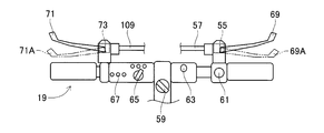
次に、ハンドル19について説明する。図5に表すように、ハンドル19は、自転車と同様のバータイプである。ハンドル19には、イグニッションスイッチ59、駆動スイッチ61、モーター作動LED63、速度設定スイッチ65、及び異常表示LED67が設けられている。イグニッションスイッチ59は、自走制御が実行される際に使用されるセレクト型のスイッチである。駆動スイッチ61は、自走制御が実行される際に使用されるモーメンタリ方式の押しボタン型のスイッチである。従って、駆動スイッチ61では、押下操作が続行された操作時にはオン状態が維持され、押下操作が解除された非操作時にはオフ状態が維持される。モーター作動LED63は、自走制御が実行される際に点灯・点滅・消灯のいずれかが行われる表示装置である。速度設定スイッチ65は、自走制御中の最高速度を低速・中速・高速のいずれかに切り替えることができるものである。本実施形態では、低速に切り替えられた際の最高速度は2km/hであり、中速に切り替えられた際の最高速度は4km/hであり、高速に切り替えられた際の最高速度は6km/hである。異常表示LED67は、自走制御が実行される際に異常が生じたときに点灯される表示装置である。自走制御については後述する。
さらに、ハンドル19には、図5視右側(前方向に対する右側)において右ブレーキレバー69が取り付けられ、図5視左側(前方向に対する左側)において左ブレーキレバー71が取り付けられている。
右ブレーキレバー69には、右アウターケーブル57の他端部が接続されており、さらに、右アウターケーブル57の中を通っている右インナーケーブル53(図3参照)の他端部が取り付けられている。
また、右ブレーキレバー69には、前輪ブレーキスイッチ55が設けられている。前輪ブレーキスイッチ55は、右インナーケーブル53のストロークを検出対象とし、右インナーケーブル53のストローク変位が第1所定距離以上の場合にオン動作する。
右ブレーキレバー69が符号69Aに示された位置に移動すると、右インナーケーブル53のストローク変位が第1所定距離に等しくなり、前輪ブレーキスイッチ55がオン動作する。右ブレーキレバー69が符号69Aに示された位置より図5視下側(ハンドル19側)に移動しても、右インナーケーブル53のストローク変位が第1所定距離より大きいので、前輪ブレーキスイッチ55がオン動作する。
前輪ブレーキスイッチ55がオン動作中は、フロント用ブレーキキャリパー51(図3参照)が作動する。従って、前輪23(図3参照)にブレーキをかける際には、運転者は右ブレーキレバー69を深く握り込むことにより、右ブレーキレバー69が符号69Aに示された位置又は右ブレーキレバー69が符号69Aに示された位置より図5視下側(ハンドル19側)に移動させる。
左ブレーキレバー71には、左アウターケーブル109の他端部が接続されており、さらに、左アウターケーブル109の中を通っている左インナーケーブル105(図4参照)の他端部が取り付けられている。
また、左ブレーキレバー71には、後輪ブレーキスイッチ73が設けられている。後輪ブレーキスイッチ73は、左インナーケーブル105のストロークを検出対象とし、左インナーケーブル105のストローク変位が第2所定距離以上の場合にオン動作する。
左ブレーキレバー71が符号71Aに示された位置に移動すると、左インナーケーブル105のストローク変位が第2所定距離に等しくなり、後輪ブレーキスイッチ73がオン動作する。左ブレーキレバー71が符号71Aに示された位置より図5視下側(ハンドル19側)に移動しても、左インナーケーブル105のストローク変位が第2所定距離より大きいので、後輪ブレーキスイッチ73がオン動作する。
後輪ブレーキスイッチ73がオン動作中は、リア用ブレーキキャリパー103(図4参照)が作動する。従って、後輪35(図4参照)にブレーキをかける際には、運転者は左ブレーキレバー71を深く握り込むことにより、左ブレーキレバー71が符号71Aに示された位置又は左ブレーキレバー71が符号71Aに示された位置より図5視下側(ハンドル19側)に移動させる。
次に、シート29について説明する。図6に表すように、シート支持フレーム27の上端部に設けられたシート29には、着座センサー77が内設されている。着座センサー77は、シート29に作用する圧力を検知し、所定値以上の圧力を検知中にオン動作する。本実施形態では、運転者がシート29に着座すると、シート29に所定値以上の圧力が作用することから、着座センサー77がオン動作する。
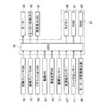
次に、モーター駆動制御ユニット37について説明する。図7に表すように、モーター駆動制御ユニット37は、CPU79、タイマー80、ROM81、及びRAM83を備えている。CPU79は、本実施形態の小型電動車両1全体の制御を行う演算装置及び制御装置である。CPU79には、タイマー80、ROM81、及びRAM83が接続されている。タイマー80は、本実施形態の小型電動車両1全体の制御を実行するための計時を行う計時装置である。尚、タイマー80に代えて、CPU79の内蔵タイマーを使用してもよいし、ソフトウエアを使用してもよい。ROM81には、各種のプログラム等が記憶されている。例えば、自走制御で使用されるプログラムや速度曲線(加速走行・定速走行・減速走行の各曲線)等は、ROM81に記憶されている。RAM83には、CPU79のデータ処理に必要なデータが一時的に記憶される。
また、CPU79には、前輪ブレーキスイッチ55、後輪ブレーキスイッチ73、イグニッションスイッチ59、駆動スイッチ61、速度設定スイッチ65、着座センサー77、加速度センサー107、ジャイロセンサー111、モーター回転数検出部86、モーター作動LED63、及び異常表示LED67が接続されている。加速度センサー107は、本実施形態の小型電動車両1の加速度を検知し、加速度を検知中にオン動作する装置であり、例えば、モーター駆動制御ユニット37内に取り付けられている。ジャイロセンサー111は、本実施形態の小型電動車両1の角度(姿勢)、つまり、水平方向に対する傾き角度(以下、「傾き角度」という。)を検出する計測装置であり、例えば、モーター駆動制御ユニット37内に取り付けられている。モーター回転数検出部86は、モーター85の回転数を検出する計測装置であり、例えば、モーター85に取り付けられている。モーター回転数検出部86の具体例としては、例えば、ホールセンサーやエンコーダ等がある。さらに、CPU79には、モーター85が接続されている。モーター85は、不図示のバッテリーを駆動源とし、前方向に対する右側の後輪35(図4参照)を電動駆動させる。尚、モーター85は、後輪35の両輪又は前輪23を電動駆動させるものであってもよい。
[2.自走制御]
以下、本実施形態の小型電動車両1で実行される自走制御について、図8及び図9を参照しつつ説明する。
以下、本実施形態の小型電動車両1で実行される自走制御について、図8及び図9を参照しつつ説明する。
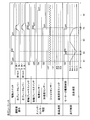
先ず、小型電動車両1が停車中における自走制御の発進シーケンスについて説明する。図8に表すように、段階A1では、駆動スイッチ61がオン状態中において、下記(1)~(5)のいずれかの状態が成立している。(1)運転者がシート29に着座していない等のため、着座センサー77がオフ動作になっている。(2)小型電動車両1が静止していない等のため、加速度センサー107がオン動作になっている。(3)小型電動車両1の傾斜が大きい等のため、ジャイロセンサー111で検出した傾斜角度が-10°以上から+10°以下の範囲外にある。(4)運転者等によって右ブレーキレバー69を深く握り込む操作が行われたため、前輪ブレーキスイッチ55がオン動作になっている。(5)運転者等によって左ブレーキレバー71を深く握り込む操作が行われたため、後輪ブレーキスイッチ73がオン動作になっている。このような場合には、運転者が押下操作を続行して駆動スイッチ61のオン状態が維持されても、モーター85の駆動制御は行われないため、小型電動車両1の停車が保たれる。尚、上記(1)~(5)の状態の一部又は全部が重複した場合でも、同様である。
これに対して、段階A2では、駆動スイッチ61がオフ状態中において、下記(6)~(10)の全ての状態が成立している。(6)運転者がシート29に着座しているため、着座センサー77がオン動作になっている。(7)小型電動車両1が静止しているため、加速度センサー107がオフ動作になっている。(8)小型電動車両1の傾斜が小さい等のため、ジャイロセンサー111で検出した傾斜角度が-10°以上から+10°以下の範囲内にある。(9)運転者によって右ブレーキレバー69から指を離す操作等が行われたため、前輪ブレーキスイッチ55がオフ動作になっている。(10)運転者によって左ブレーキレバー71から指を離す操作等が行われたため、後輪ブレーキスイッチ73がオフ動作になっている。
このような場合において、運転者が押下操作を行うことにより駆動スイッチ61がオフ状態からオン状態に切り替えられると共に、運転者が押下操作を続行することにより駆動スイッチ61のオン状態が維持されると、モーター85の駆動制御が開始される。このモーター85の駆動制御により、後輪35(図4参照)が電動駆動されるので、小型電動車両1が発進し、小型電動車両1の自走速度が最高速度になるまで一律に加速する加速走行が行われる。そして、小型電動車両1の自走速度が最高速度に到達すると、小型電動車両1が最高速度で自走する定速走行が行われる。
本実施形態では、段階A2の発進時において、速度設定スイッチ65により最高速度が低速に設定されているので、小型電動車両1は、0km/hから2km/hまで一律に加速走行したのちに2km/hで定速走行する。
尚、図8には表されていないが、発進時において、速度設定スイッチ65により最高速度が中速に設定されている場合には、小型電動車両1は、0km/hから4km/hまで一律に加速走行したのちに4km/hで定速走行する。或いは、発進時において、速度設定スイッチ65により最高速度が高速に設定されている場合には、小型電動車両1は、0km/hから6km/hまで一律に加速走行したのちに6km/hで定速走行する。
また、段階A2では、2km/hで定速走行の自走時において、速度設定スイッチ65により最高速度が低速から中速に切り替えられると、小型電動車両1は、2km/hから4km/hまで一律に加速走行したのちに4km/hで定速走行する。その4km/hで定速走行の自走時において、速度設定スイッチ65により最高速度が中速から高速に切り替えられると、小型電動車両1は、4km/hから6km/hまで一律に加速走行したのちに6km/hで定速走行する。
尚、図8には表されていないが、2km/hの定速走行の自走時において、速度設定スイッチ65により最高速度が低速から高速に切り替えられると、小型電動車両1は、2km/hから6km/hまで一律に加速走行したのちに6km/hで定速走行する。
また、2km/hまでの加速走行時において、速度設定スイッチ65により最高速度が低速から中速に切り替えられると、小型電動車両1は、4km/hまで一律に加速走行したのちに4km/hで定速走行する。或いは、4km/hまでの加速走行時において、速度設定スイッチ65により最高速度が中速から高速に切り替えられると、小型電動車両1は、6km/hまで一律に加速走行したのち6km/hで定速走行する。
また、小型電動車両1の発進後においては、上記(7)の状態(加速度センサー107がオフ動作になっていること)を除き、上記(6)、(8)~(10)の全ての状態が成立している場合には、駆動スイッチ61のオン状態が維持されている限り、小型電動車両1の加速走行又は定速走行が続行される。
次に、小型電動車両1が自走中における自走制御の走行シーケンスについて、図9を用いて説明する。図9では、説明の便宜上、小型電動車両1の最高速度は、速度設定スイッチ65により高速の6km/hに設定されている。尚、低速の2km/h又は中速の4km/hに設定されていても、同様な走行シーケンスが適合する。
図9に表すように、段階B1では、モーター85の駆動制御が行われており、小型電動車両1が最高速度(6km/h)で定速走行中である。このような場合において、運転者が駆動スイッチ61の押下操作を解除することにより、駆動スイッチ61がオン状態からオフ状態に切り替えられると共に、駆動スイッチ61のオフ状態が維持されると、モーター85の駆動制御により、小型電動車両1の減速走行が行われる。減速走行とは、小型電動車両1の自走速度が予め定められた最低速度(本実施形態では、速度設定スイッチ65で設定される低速の2km/hより遅い速度)になるまで一律に減速することである。尚、図9には表されていないが、小型電動車両1が加速走行中であっても、同様にして、減速走行が行われる。
段階B2では、小型電動車両1の自走速度が最低速度に到達すると、モーター85への電力供給が遮断されて、モーター85の駆動制御が止められる。このような場合には、モーター85が惰性で回転し続けるフリーラン状態になり、摩擦抵抗等によって、小型電動車両1の自走速度は遅くなっていく。
段階B3では、モーター85がフリーラン状態である場合において、運転者が押下操作を行うことにより駆動スイッチ61がオフ状態からオン状態に切り替えられると共に、運転者が押下操作を続行することにより駆動スイッチ61のオン状態が維持されると、モーター85の駆動制御が再開される。このモーター85の駆動制御により、後輪35(図4参照)が電動駆動されるので、小型電動車両1が再加速し、小型電動車両1の自走速度が最高速度(6km/h)になるまで一律に加速する加速走行が行われる。そして、小型電動車両1の自走速度が最高速度(6km/h)に到達すると、小型電動車両1が最高速度(6km/h)で自走する定速走行が行われる。
このような場合においても、運転者が駆動スイッチ61の押下操作を解除することにより、駆動スイッチ61がオン状態からオフ状態に切り替えられると共に、駆動スイッチ61のオフ状態が維持されると、上記段階B1と同様にして、小型電動車両1の減速走行が行われる。
尚、図9には表されていないが、駆動スイッチ61がオン状態中、つまり、小型電動車両1が加速走行中又は定速走行中においても、ジャイロセンサー111で検出した傾斜角度が-10°以上から+10°以下の範囲外になれば、小型電動車両1の減速走行が行われる。但し、-10°以上から+10°以下の範囲は、一例であって、これに限るものでない。
段階B4では、小型電動車両1の自走速度が最低速度に到達する前において、運転者によって右ブレーキレバー69又は左ブレーキレバー71を深く握り込む操作が行われることにより、前輪ブレーキスイッチ55又は後輪ブレーキスイッチ73がオン動作になると、モーター85への電力供給が遮断されて、モーター85の駆動制御が止められる。このような場合には、モーター85がフリーラン状態になる。
同時に、フロント用ブレーキキャリパー51又はリア用ブレーキキャリパー103の作動が開始される。つまり、前輪ブレーキスイッチ55のオン動作中は、右ブレーキレバー69の握込操作によってフロント用ブレーキキャリパー51が作動するので、フロント用ブレーキキャリパー51による機械的制動を前輪23にかけることができる。又は、後輪ブレーキスイッチ73のオン動作中は、左ブレーキレバー71の握込操作によってリア用ブレーキキャリパー103が作動するので、リア用ブレーキキャリパー103による機械的制動を後輪35にかけることができる。
尚、図9の段階B4では、記載の便宜上、運転者によって右ブレーキレバー69及び左ブレーキレバー71を同時に深く握り込む操作が行われることにより、前輪ブレーキスイッチ55及び後輪ブレーキスイッチ73が同時にオン動作になる場合が記載されているが、操作(オン動作)が同時に行われる必要はない。
また、図9には表されていないが、駆動スイッチ61がオン状態中であっても、つまり、小型電動車両1が加速走行中又は定速走行中であっても、運転者によって右ブレーキレバー69又は左ブレーキレバー71を深く握り込む操作が行われることにより、前輪ブレーキスイッチ55又は後輪ブレーキスイッチ73がオン動作になれば、モーター85の駆動制御が止められてモーター85がフリーラン状態になり、フロント用ブレーキキャリパー51又はリア用ブレーキキャリパー103の機械的制動が行われる。
段階B5では、フロント用ブレーキキャリパー51又はリア用ブレーキキャリパー103の機械的制動により、小型電動車両1の自走速度が0km/hに到達し、小型電動車両1が停止されると、加速度センサー107がオフ動作になる。また、運転者によって右ブレーキレバー69又は左ブレーキレバー71から指を離す操作が行われることにより、前輪ブレーキスイッチ55又は後輪ブレーキスイッチ73がオフ動作になる。さらに、運転者がシート29から離れることにより、着座センサー77がオフ動作になる。
尚、本実施形態の機械的制動は、上述したように、左右のアウターケーブル57,109によってフロント用ブレーキキャリパー51又はリア用ブレーキキャリパー103を作動させることで行われている。このようにして、フロント用ブレーキキャリパー51又はリア用ブレーキキャリパー103の作動は、ワイヤーによって行われているが、電気又は油圧等によって作動させてもよい。
尚、図9の段階B5でも、記載の便宜上、運転者によって右ブレーキレバー69及び左ブレーキレバー71から同時に指を離す操作が行われることにより、前輪ブレーキスイッチ55及び後輪ブレーキスイッチ73が同時にオフ動作になる場合が記載されているが、操作(オン動作)が同時に行われる必要はない。
また、図9には表されていないが、モーター85の駆動制御が止められることにより、モーター85がフリーラン状態になっている場合には、上記(1)の状態(着座センサー77がオフ動作になっていること)、上記(7)の状態(加速度センサー107がオフ動作になっていること)、上記(9)の状態(前輪ブレーキスイッチ55がオフ動作になっていること)、又は上記(10)の状態(後輪ブレーキスイッチ73がオフ動作になっていること)のいずれかが成立していれば、図8の段階A1に移行される。
以上より、運転者は、左右のブレーキレバー69,71から指を離す操作を行うと共に、駆動スイッチ61の押下操作を続行すれば、本実施形態の小型電動車両1を電動駆動によって発進・加速走行・定速走行させることができる。その後、運転者は、駆動スイッチ61の押下操作を解除すれば、本実施形態の小型電動車両1を電動駆動によって最低速度まで減速走行させることができる。さらに、電動駆動中の運転者は、駆動スイッチ61の押下操作が行われているか否かに関係なく、右ブレーキレバー69又は左ブレーキレバー71を深く握り込む操作を行えば、電動駆動が止められ、本実施形態の小型電動車両1を機械的制動によって減速又は停車させることができる。尚、本実施形態の小型電動車両1が減速して自走速度が最低速度になるときも、電動駆動が止められる。
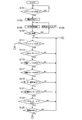
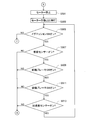
次に、本実施形態の小型電動車両1で実行される自走制御のプログラムについて、図10乃至図18に表すフローチャートを用いて説明する。自走制御のプログラムは、ROM81に記憶されており、CPU79により実行される。
図10に表すように、CPU79は、この自走制御のプログラムの実行を開始し、イグニッションスイッチ59がオン動作されているか否かを判別する(S101)。ここで、イグニッションスイッチ59がオフ動作されている場合には(S101:NO)、CPU79は、イグニッションスイッチ59がオン動作されているか否かを再び判別する(S101)。又は、イグニッションスイッチ59がオン動作されている場合には(S101:YES)、CPU79は、電源供給をオンする(103)。
その後、CPU79は、CPU79自身の異常を確認する(S105)。そして、CPU79自身に異常がある場合には(S107:YES)、CPU79は、異常表示LED67を点灯させ(S109)、CPU79自身の異常を再び確認する(S105)。
又は、CPU79自身に異常がない場合には(S107:NO)、CPU79は、イグニッションスイッチ59がオン動作されているか否かを判別する(S111)。このとき、異常表示LED67が点灯していれば、CPU79は、異常表示LED67を消灯させる。
ここで、イグニッションスイッチ59がオフ動作されている場合には(S111:NO)、CPU79は、後述する図18に記載されたS701の処理を行う。又は、イグニッションスイッチ59がオン動作されている場合には(S111:YES)、CPU79は、着座センサー77がオン動作されているか否かを判別する(S113)。
ここで、着座センサー77がオフ動作されている場合には(S113:NO)、CPU79は、イグニッションスイッチ59がオン動作されているか否かを再び判別する(S111)。又は、着座センサー77がオン動作されている場合には(S113:YES)、CPU79は、前輪ブレーキスイッチ55がオフ動作されているか否かを判別する(S115)。
ここで、前輪ブレーキスイッチ55がオン動作されている場合には(S115:NO)、CPU79は、イグニッションスイッチ59がオン動作されているか否かを再び判別する(S111)。又は、前輪ブレーキスイッチ55がオフ動作されている場合には(S115:YES)、CPU79は、後輪ブレーキスイッチ73がオフ動作されているか否かを判別する(S117)。
ここで、後輪ブレーキスイッチ73がオン動作されている場合には(S117:NO)、CPU79は、イグニッションスイッチ59がオン動作されているか否かを再び判別する(S111)。又は、後輪ブレーキスイッチ73がオフ動作されている場合には(S117:YES)、CPU79は、モーター回転信号がオフであるか否かを判別する(S119)。この判別は、モーター回転数検出部86の出力信号に基づいて行われる。
ここで、モーター回転信号がオンである場合には(S119:NO)、CPU79は、イグニッションスイッチ59がオン動作されているか否かを再び判別する(S111)。又は、モーター回転信号がオフである場合には(S119:YES)、CPU79は、加速度センサー107がオフ動作されているか否かを判別する(S121)。
ここで、加速度センサー107がオン動作されている場合には(S121:NO)、CPU79は、イグニッションスイッチ59がオン動作されているか否かを再び判別する(S111)。又は、加速度センサー107がオフ動作されている場合には(S121:YES)、CPU79は、ジャイロセンサー111で検出した傾斜角度が-10°以上から+10°以下の範囲内にあるか否かを判別する(S123)。
ここで、ジャイロセンサー111で検出した傾斜角度が-10°以上から+10°以下の範囲外にある場合には(S123:NO)、CPU79は、イグニッションスイッチ59がオン動作されているか否かを再び判別する(S111)。又は、ジャイロセンサー111で検出した傾斜角度が-10°以上から+10°以下の範囲内にある場合には(S123:YES)、CPU79は、駆動スイッチ61がオン状態にあるか否かを判別する(S125)。
ここで、駆動スイッチ61がオフ状態にある場合には(S125:NO)、CPU79は、イグニッションスイッチ59がオン動作されているか否かを再び判別する(S111)。又は、駆動スイッチ61がオン状態にある場合には(S125:YES)、CPU79は、図11に表すように、モーター加速処理を行う(S127)。
モーター加速処理では、CPU79は、ROM81に記憶の速度曲線(加速の曲線)に基づいて、モーター85の駆動制御を行うことにより、小型電動車両1の加速走行を行う。このとき、小型電動車両1が停車中であれば、小型電動車両1の発進が行われる。
その後、CPU79は、モーター作動LED63を点灯させ(S129)、検出処理を行う(S131)。
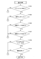
検出処理では、図12に表すように、CPU79は、イグニッションスイッチ59がオン動作されているか否かを判別する(S1001)。ここで、イグニッションスイッチ59がオフ動作されている場合には(S1001:NO)、CPU79は、後述する図18に記載されたS701の処理を行う。又は、イグニッションスイッチ59がオン動作されている場合には(S1001:YES)、CPU79は、着座センサー77がオン動作されているか否かを判別する(S1003)。
ここで、着座センサー77がオフ動作されている場合には(S1003:NO)、CPU79は、後述する図17に記載されたS601の処理を行う。又は、着座センサー77がオン動作されている場合には(S1003:YES)、CPU79は、前輪ブレーキスイッチ55がオフ動作されているか否かを判別する(S1005)。
ここで、前輪ブレーキスイッチ55がオン動作されている場合には(S1005:NO)、CPU79は、後述する図16に記載されたS501の処理を行う。又は、前輪ブレーキスイッチ55がオフ動作されている場合には(S1005:YES)、CPU79は、後輪ブレーキスイッチ73がオフ動作されているか否かを判別する(S1007)。
ここで、後輪ブレーキスイッチ73がオン動作されている場合には(S1007:NO)、CPU79は、後述する図16に記載されたS501の処理を行う。又は、後輪ブレーキスイッチ73がオフ動作されている場合には(S1007:YES)、CPU79は、ジャイロセンサー111で検出した傾斜角度が-10°以上から+10°以下の範囲内にあるか否かを判別する(S1009)。
ここで、ジャイロセンサー111で検出した傾斜角度が-10°以上から+10°以下の範囲外にある場合には(S1009:NO)、CPU79は、図14に記載されたS401の処理を行う。又は、ジャイロセンサー111で検出した傾斜角度が-10°以上から+10°以下の範囲内にある場合には(S1009:YES)、CPU79は、駆動スイッチ61がオン状態にあるか否かを判別する(S1011)。
ここで、駆動スイッチ61がオフ状態にある場合には(S1011:NO)、CPU79は、図14に記載されたS401の処理を行う。又は、駆動スイッチ61がオン状態にある場合には(S1011:YES)、図11に表すように、CPU79は、モーター85の回転数を確認する(S133)。この確認は、モーター回転数検出部86の出力信号に基づいて行われる。
そして、CPU79は、モーター85の回転数が設定回転数未満であるか否かを判別する(S135)。設定回転数とは、速度設定スイッチ65により設定された速度に対応するモーター85の回転数であり、ROM81に記憶されている。本実施形態では、速度設定スイッチ65により低速(2km/h)に設定された場合には、モーター85の回転数は708rpmである。中速(4km/h)に設定された場合には、モーター85の回転数は1416rpmである。高速(6km/h)に設定された場合には、モーター85の回転数は2123rpmである。尚、これらの回転数は、モーター85の減速比と駆動輪(本実施形態では、後輪35)の径とにより決まるものであるから、これらの数値に限定されるものでない。
ここで、モーター85の回転数が設定回転数未満である場合には(S135:YES)、つまり、速度設定スイッチ65で設定された速度に比べて小型電動車両1の自走速度が遅い場合には、CPU79は、検出処理を再び行う(S131)。又は、モーター85の回転数が設定回転数以上である場合には(S135:YES)、つまり、速度設定スイッチ65で設定された速度に比べて小型電動車両1の自走速度が速い場合には、図13に表すように、CPU79は、モーター定速処理を行う(S201)。
モーター定速処理では、CPU79は、ROM81に記憶の速度曲線(定速の曲線)に基づいて、モーター85の駆動制御を行うことにより、速度設定スイッチ65で設定された速度を自走速度とした小型電動車両1の定速走行を行う。
その後、CPU79は、検出処理を行う(S203)。この検出処理(S203)は、上述した図12に記載の検出処理と同様である。従って、駆動スイッチ61がオン状態にある場合には(S1011:YES)、図13に表すように、CPU79は、モーター85の回転数を確認する(S205)。
そして、CPU79は、モーター85の回転数と設定回転数との差が設定回転数の-10%以上から+10%以下の範囲内にあるか否かを判別する。ここで、モーター85の回転数と設定回転数との差が設定回転数の-10%以上から+10%以下の範囲内にある場合には(S207:YES)、CPU79は、検出処理を再び行う(S203)。又は、モーター85の回転数と設定回転数との差が設定回転数の-10%以上から+10%以下の範囲外にある場合には(S207:NO)、図14に表すように、CPU79は、モーター再加速処理を行う(S301)。
モーター再加速処理では、CPU79は、ROM81に記憶の速度曲線(加速の曲線)に基づいて、モーター85の駆動制御を行うことにより、小型電動車両1の加速走行を行う。尚、図10乃至図18に表すフローチャートに従えば、小型電動車両1が停車中のときは、モーター再加速処理は行われない。
その後、CPU79は、モーター作動LED63を点灯させ(S303)、検出処理を行う(S305)。
この検出処理(S305)は、上述した図12に記載の検出処理と同様である。従って、駆動スイッチ61がオン状態にある場合には(S1011:YES)、図14に表すように、CPU79は、モーター85の回転数を確認する(S307)。
そして、CPU79は、モーター85の回転数が設定回転数未満であるか否かを判別する(S309)。ここで、モーター85の回転数が設定回転数未満である場合には(S309:YES)、つまり、速度設定スイッチ65で設定された速度に比べて小型電動車両1の自走速度が遅い場合には、CPU79は、検出処理を再び行う(S305)。又は、モーター85の回転数が設定回転数以上の場合には(S309:NO)、つまり、速度設定スイッチ65で設定された速度に比べて小型電動車両1の自走速度が速い場合には、図14に表すように、CPU79は、上述した図13に記載のモーター定速処理を行う(S201)。
次に、図15に記載のモーター減速処理(S401)が行われる場合について説明する。CPU79は、上述したように、ジャイロセンサー111で検出した傾斜角度が-10°以上から+10°以下の範囲外にある場合(S1009:NO)、又は駆動スイッチ61がオフ状態にある場合には(S1011:NO)、図15に記載されたモーター減速処理を行う(S401)。
モーター減速処理では、CPU79は、ROM81に記憶の速度曲線(減速の曲線)に基づいて、例えば、モーター85の駆動制御を行うことにより、小型電動車両1の減速走行を行う。尚、小型電動車両1の減速走行時には、回生制動又は相間短絡等の電動制動が行われてもよい。
その後、CPU79は、モーター作動LED63を点滅させ(S403)、イグニッションスイッチ59がオン動作されているか否かを判別する(S405)。
ここで、イグニッションスイッチ59がオフ動作されている場合には(S405:NO)、CPU79は、後述する図18に記載されたS701の処理を行う。又は、イグニッションスイッチ59がオン動作されている場合には(S405:YES)、CPU79は、前輪ブレーキスイッチ55がオフ動作されているか否かを判別する(S407)。
ここで、前輪ブレーキスイッチ55がオン動作されている場合には(S407:NO)、CPU79は、後述する図16に記載されたS501の処理を行う。又は、前輪ブレーキスイッチ55がオフ動作されている場合には(S407:YES)、CPU79は、後輪ブレーキスイッチ73がオフ動作されているか否かを判別する(S409)。
ここで、後輪ブレーキスイッチ73がオン動作されている場合には(S409:NO)、CPU79は、後述する図16に記載されたS501の処理を行う。又は、後輪ブレーキスイッチ73がオフ動作されている場合には(S409:YES)、CPU79は、駆動スイッチ61がオフ状態にあるか否かを判別する(S411)。
ここで、駆動スイッチ61がオン状態にある場合には(S411:NO)、CPU79は、上述した図14に記載のモーター再加速処理を行う(S301)。又は、駆動スイッチ61がオフ状態にある場合には(S411:YES)、CPU79は、モーター85の回転数を確認する(S413)。
そして、CPU79は、モーター85の回転数が設定回転数以下であるか否かを判別する(S415)。尚、S415での設定回転数とは、これまで(S135,S207,S309)の設定回転数とは異なり、ROM81に予め記憶された最低速度(本実施形態では、速度設定スイッチ65で設定される低速の2km/hより遅い速度)に対応する、モーター85の回転数をいう。
ここで、モーター85の回転数が設定回転数より多い場合には(S415:NO)、つまり、最低速度に比べて小型電動車両1の自走速度が速い場合には、CPU79は、イグニッションスイッチ59がオン動作されているか否かを再び判別する(S405)。又は、モーター85の回転数が設定回転数以下である場合には(S415:YES)、つまり、最低速度に比べて小型電動車両1の自走速度が遅い場合には、CPU79は、図16に表すように、モーター停止処理を行う(S501)。
モーター停止処理では、CPU79は、不図示のバッテリーの電力供給線からモーター85を切り離すことにより、モーター85をフリーラン状態にする。尚、CPU79は、上述したように、前輪ブレーキスイッチ55がオン動作されている場合(S1005:NO)、後輪ブレーキスイッチ73がオン動作されている場合(S1007:NO)、前輪ブレーキスイッチ55がオン動作されている場合(S407:NO)、又は後輪ブレーキスイッチ73がオン動作されている場合には(S409:NO)にも、モーター停止処理を行う。
その後、CPU79は、モーター作動LED63を消灯させ(S503)、イグニッションスイッチ59がオン動作されているか否かを判別する(S505)。
ここで、イグニッションスイッチ59がオフ動作されている場合には(S505:NO)、CPU79は、後述する図18に記載されたS701の処理を行う。又は、イグニッションスイッチ59がオン動作されている場合には(S505:YES)、CPU79は、着座センサー77がオン動作されているか否かを判別する(S507)。
ここで、着座センサー77がオフ動作されている場合には(S507:NO)、CPU79は、上述した図10に記載のS111の処理、つまり、イグニッションスイッチ59がオン動作されているか否かを再び判別する(S111)。又は、着座センサー77がオン動作されている場合には(S507:YES)、CPU79は、前輪ブレーキスイッチ55がオン動作されているか否かを判別する(S509)。
ここで、前輪ブレーキスイッチ55がオフ動作されている場合には(S509:NO)、CPU79は、上述した図10に記載のS111の処理、つまり、イグニッションスイッチ59がオン動作されているか否かを再び判別する(S111)。又は、前輪ブレーキスイッチ55がオン動作されている場合には(S509:YES)、CPU79は、後輪ブレーキスイッチ73がオン動作されているか否かを判別する(S511)。
ここで、後輪ブレーキスイッチ73がオフ動作されている場合には(S511:NO)、CPU79は、上述した図10に記載のS111の処理、つまり、イグニッションスイッチ59がオン動作されているか否かを再び判別する(S111)。又は、後輪ブレーキスイッチ73がオン動作されている場合には(S511:YES)、CPU79は、加速度センサー107がオン動作されているか否かを判別する(S513)。
ここで、加速度センサー107がオフ動作されている場合には(S513:NO)、CPU79は、上述した図10に記載のS111の処理、つまり、イグニッションスイッチ59がオン動作されているか否かを再び判別する(S111)。又は、加速度センサー107がオン動作されている場合には(S121:YES)、CPU79は、この図16に記載のS505の処理、つまり、イグニッションスイッチ59がオン動作されているか否かを再び判別する(S505)。
次に、図17に記載のタイマー作動処理(S601)が行われる場合について説明する。CPU79は、上述したように、着座センサー77がオフ動作されている場合には(S1003:NO)、図17に記載されたタイマー作動処理を行う(S601)。
タイマー作動処理では、CPU79は、タイマー80を使用して計時を開始する。
その後、CPU79は、着座センサー77のオフ動作の継続時間がタイマー設定時間以上であるか否かを判別する(S603)。この判別では、上述したS601のタイマー80による計時結果が利用される。尚、タイマー設定時間は、ROM81に予め記憶されている。
ここで、着座センサー77のオフ動作の継続時間がタイマー設定時間未満である場合には(S603:YES)、CPU79は、運転者がシート29に着座しているとして、上述した図11に記載の検出処理(S131)を行う。又は、着座センサー77のオフ動作の継続時間がタイマー設定時間以上である場合には(S603:YES)、CPU79は、運転者がシート29から離れているとして、上述した図15のモーター減速処理(S401)を行う。
このようにして、着座センサー77がオフ動作した際の対応がなされることにより、小型電動車両1が加速走行中、定速走行中、又は再加速走行中における、着座センサー77のチャタリング対策が施されている。
次に、CPU79は、イグニッションスイッチ59がオフ動作されている場合には(S111:NO,S1001:NO,S405:NO,S505:NO)、上述したように、図18に記載のモーター停止処理を行う(S701)。モーター停止処理は、上述した図16に記載のモーター停止処理(S501)と同様である。
その後、CPU79は、モーター作動LED63等のLEDを消灯し(S703)、RAM83等のメモリーをリセットする(S705)。さらに、CPU79は、電源供給をオフし(S707)、CPU79自身を待機モードにして、この自走制御のプログラムの実行を終了する。
[3.-1 加速走行時と定速走行時のまとめ]
本実施形態の小型電動車両1では、自走の開始に当たり、運転者は、右ブレーキレバー69及び左ブレーキレバー71から指を離す操作等を行うと共に、駆動スイッチ61の押下操作を続行する。これにより、右ブレーキレバー69のストローク量が第1所定距離未満となり(S115:YES)、左ブレーキレバー71のストローク量が第2所定距離未満となり(S117:YES)、及び駆動スイッチ61がオン状態に維持される(S125:YES)。このような状況に応じて、モーター85の駆動制御が行われることにより(S127,S201)、本実施形態の小型電動車両1は、速度設定スイッチ65の設定速度まで加速走行を行ったのちに、速度設定スイッチ65の設定速度を自走速度とした定速走行を行う。
本実施形態の小型電動車両1では、自走の開始に当たり、運転者は、右ブレーキレバー69及び左ブレーキレバー71から指を離す操作等を行うと共に、駆動スイッチ61の押下操作を続行する。これにより、右ブレーキレバー69のストローク量が第1所定距離未満となり(S115:YES)、左ブレーキレバー71のストローク量が第2所定距離未満となり(S117:YES)、及び駆動スイッチ61がオン状態に維持される(S125:YES)。このような状況に応じて、モーター85の駆動制御が行われることにより(S127,S201)、本実施形態の小型電動車両1は、速度設定スイッチ65の設定速度まで加速走行を行ったのちに、速度設定スイッチ65の設定速度を自走速度とした定速走行を行う。
つまり、運転者は、駆動スイッチ61を押下操作するだけで、小型電動車両1の加速走行又は定速走行を行わせることができる。よって、本実施形態の小型電動車両1は、自走操作中の運転者に疲労感を与えることがない。また、駆動スイッチ61の押下操作及び左右のブレーキレバー69,71から指を離す操作等によって、運転者の意思に合わせた加速走行又は定速走行が行える。
本実施形態の小型電動車両1では、自走中の運転者が、右ブレーキレバー69又は左ブレーキレバー71を深く握り込む操作を行う場合がある。このような場合には、右ブレーキレバー69が符号69Aに示された位置又は符号69Aに示された位置より図5視下側(ハンドル19側)にあるときに、右ブレーキレバー69のストローク量が第1所定距離以上となる(S1005:NO,S407:NO)。或いは、左ブレーキレバー71が符号71Aに示された位置又は符号71Aに示された位置より図5視下側(ハンドル19側)にあるときに、左ブレーキレバー71のストローク量が第2所定距離以上となる(S1007:NO,S409:NO)。
このような状況に応じて、本実施形態の小型電動車両1では、右ブレーキレバー69又は左ブレーキレバー71による機械的制動が行われる(S509:YES,S511:YES)。よって、駆動スイッチ61の押下操作が行われるか否かに関係なく、今まで慣れ親しんだ左右のブレーキレバー69,71の握込操作により、小型電動車両1を減速又は停車させることができるので、安全性が確保される。
以上より、本実施形態の小型電動車両1では、操作性及び安全性が向上する。
[3.-2 機械的制動時のまとめ]
本実施形態の小型電動車両1では、右ブレーキレバー69又は左ブレーキレバー71による機械的制動が行われる際には(S509:YES,S511:YES)、モーター85への電力供給が遮断されてモーター85がフリーラン状態になっているので(S501)、効率的な機械的制動が行われる。
本実施形態の小型電動車両1では、右ブレーキレバー69又は左ブレーキレバー71による機械的制動が行われる際には(S509:YES,S511:YES)、モーター85への電力供給が遮断されてモーター85がフリーラン状態になっているので(S501)、効率的な機械的制動が行われる。
[3.-3 減速走行時のまとめ]
本実施形態の小型電動車両1では、自走中の運転者が左右のブレーキレバー69,71から指を離す操作等を行っていると、右ブレーキレバー69のストローク量が第1所定距離未満となり(S1005:YES)、左ブレーキレバー71のストローク量が第2所定距離未満となる(S1007:YES)。このような場合において、運転者は、駆動スイッチ61の押下操作を解除して、駆動スイッチ61をオフ状態にすると(S1011:NO)、モーター85の駆動制御が行われることにより(S401)、最低速度まで減速走行する(S415:NO)。
本実施形態の小型電動車両1では、自走中の運転者が左右のブレーキレバー69,71から指を離す操作等を行っていると、右ブレーキレバー69のストローク量が第1所定距離未満となり(S1005:YES)、左ブレーキレバー71のストローク量が第2所定距離未満となる(S1007:YES)。このような場合において、運転者は、駆動スイッチ61の押下操作を解除して、駆動スイッチ61をオフ状態にすると(S1011:NO)、モーター85の駆動制御が行われることにより(S401)、最低速度まで減速走行する(S415:NO)。
つまり、運転者は、左右のブレーキレバー69,71を操作することなく、駆動スイッチ61の押下操作を解除するだけで、小型電動車両1の減速走行を行わせることができる。よって、本実施形態の小型電動車両1では、駆動スイッチ61の押下操作を解除することによって、急停止することなく、運転者の意思に合わせた減速走行が行える。
本実施形態の小型電動車両1では、モーター85は、最低速度まで減速することに応じて、電力供給が遮断されてフリーラン状態になる(S415:YES,S501)。よって、小型電動車両1の自走速度が最低速度未満である場合には、今まで慣れ親しんだ左右のブレーキレバー69,71の握込操作によって、急停止することなく、小型電動車両1を減速又は停車させることができる。
[3.-4 ジャイロセンサーのまとめ]
本実施形態の小型電動車両1では、ジャイロセンサー111で検出した傾斜角度が-10°以上から+10°以下の範囲外である場合には、発進時にあっては、モーター85の駆動が禁止され(S123:NO)、自走時にあっては、モーター85の駆動制御が行われることにより、最低速度まで減速走行する(S1009:NO,S401,S415:NO)。よって、発進時又は自走時の安定条件として、小型電動車両1の水平方向に対する傾き角度を利用することが可能である。
本実施形態の小型電動車両1では、ジャイロセンサー111で検出した傾斜角度が-10°以上から+10°以下の範囲外である場合には、発進時にあっては、モーター85の駆動が禁止され(S123:NO)、自走時にあっては、モーター85の駆動制御が行われることにより、最低速度まで減速走行する(S1009:NO,S401,S415:NO)。よって、発進時又は自走時の安定条件として、小型電動車両1の水平方向に対する傾き角度を利用することが可能である。
[3.-5 駆動スイッチとブレーキレバーの位置関係のまとめ]
本実施形態の小型電動車両1では、駆動スイッチ61が右ブレーキレバー69に隣接して設けられている。運転者は、駆動スイッチ61を押下する操作を行う際は、図19(a)に表すように、親指で駆動スイッチ61を押下する。このような場合には、親指以外の4本の指は、例えば、ハンドル19に設けられたグリップ113を握っており、右ブレーキレバー69から離れている。一方、運転者は、右ブレーキレバー69を握り込む操作を行う際は、例えば、図19(b)に表すように、親指でグリップ113を握ると共に、親指以外の4本の指で右ブレーキレバー69を握り込む。
本実施形態の小型電動車両1では、駆動スイッチ61が右ブレーキレバー69に隣接して設けられている。運転者は、駆動スイッチ61を押下する操作を行う際は、図19(a)に表すように、親指で駆動スイッチ61を押下する。このような場合には、親指以外の4本の指は、例えば、ハンドル19に設けられたグリップ113を握っており、右ブレーキレバー69から離れている。一方、運転者は、右ブレーキレバー69を握り込む操作を行う際は、例えば、図19(b)に表すように、親指でグリップ113を握ると共に、親指以外の4本の指で右ブレーキレバー69を握り込む。
このようにして、本実施形態の小型電動車両1では、駆動スイッチ61が右ブレーキレバー69の周辺に設けられており、右ブレーキレバー69と駆動スイッチ61とを運転者の操作対象として容易に切り替えることができるので、操作性をより向上させることが可能である。また、駆動スイッチ61が右ブレーキレバー69に隣接して設けられているので、運転者は、自転車の操作に慣れていれば、右ブレーキレバー69を操作すると同時に、駆動スイッチ61を操作することは難しい。尚、図示はしないが、駆動スイッチ61が左ブレーキレバー71の周辺に設けられた場合でも、同様である。
[3.-6 着座判別のまとめ]
本実施形態の小型電動車両1では、着座センサー77がオン動作されているか否かによって、運転者がシート29から離れているか否かを判別し(S113)、運転者がシート29から離れている場合には(S113:NO)、自走制御プログラムを進行させることが禁止される。よって、シート29に運転者が着座していない状態でモーター85の駆動が実行されることを防止できる。
本実施形態の小型電動車両1では、着座センサー77がオン動作されているか否かによって、運転者がシート29から離れているか否かを判別し(S113)、運転者がシート29から離れている場合には(S113:NO)、自走制御プログラムを進行させることが禁止される。よって、シート29に運転者が着座していない状態でモーター85の駆動が実行されることを防止できる。
[4.その他]
本実施形態の小型電動車両1では、自走制御プログラムにおいて、モーター停止処理(S501)が行われると、モーター85は、例えば、インバータから電力供給が遮断される技術等によって、フリーラン状態(惰性回転)になる。つまり、モーター85による自走が終了すると、モーター85で駆動される後輪35が自由に回転できる状態になる。従って、本実施形態の小型電動車両1では、モーター85による自走が終了すると、前輪23及び一対の後輪35を自由に回転させることにより移動できるので、緊急時や折畳状態時等の移動が容易である。
本実施形態の小型電動車両1では、自走制御プログラムにおいて、モーター停止処理(S501)が行われると、モーター85は、例えば、インバータから電力供給が遮断される技術等によって、フリーラン状態(惰性回転)になる。つまり、モーター85による自走が終了すると、モーター85で駆動される後輪35が自由に回転できる状態になる。従って、本実施形態の小型電動車両1では、モーター85による自走が終了すると、前輪23及び一対の後輪35を自由に回転させることにより移動できるので、緊急時や折畳状態時等の移動が容易である。
ちなみに、本実施形態において、右ブレーキレバー69は、「ブレーキレバー」の一例である。右ブレーキレバー69が符号69Aに示された位置にあるときのレバー操作量は、「所定操作量」の一例である。左ブレーキレバー71は、「ブレーキレバー」の一例である。左ブレーキレバー71が符号71Aに示された位置にあるときのレバー操作量は、「所定操作量」の一例である。速度設定スイッチ65で低速に切り替えられたときの最高速度である2km/h、中速に切り替えられたときの最高速度である4km/h、又は高速に切り替えられたときの最高速度である6km/hは、「第1所定速度」の一例である。予め設定された最低速度(本実施形態では、速度設定スイッチ65で設定される低速の2km/hより遅い速度)は、「第2所定速度」の一例である。傾斜角度が-10°以上から+10°以下である範囲は、「所定範囲」の一例である。シート29は、「座席」の一例である。
[5.変更例]
尚、本発明は上記実施形態に限定されるものでなく、その趣旨を逸脱しない範囲で様々な変更が可能である。
例えば、本実施形態の小型電動車両1では、押しボタン型の駆動スイッチ61に代えて、図20に表すようなテープスイッチ115を使用してもよい。このような場合には、ハンドル19に設けられたグリップ113において、右ブレーキレバー69に対向するようにして、テープスイッチ115が設けられる。運転者は、テープスイッチ115をオン状態にする操作を行う際は、例えば、図20(a)に表すように、親指でグリップ113を握ると共に、親指以外の4本の指でグリップ113をテープスイッチ115を介して握り込む。これにより、運転者は、親指を立てることなく、テープスイッチ115を押下状態にすることが可能である。一方、運転者は、右ブレーキレバー69を握り込む操作を行う際は、例えば、図19(b)に表すように、親指でグリップ113を握ると共に、親指以外の4本の指で右ブレーキレバー69を握り込む。尚、図示はしないが、テープスイッチ115は、左ブレーキレバー71の周辺に設けられてもよい。
尚、本発明は上記実施形態に限定されるものでなく、その趣旨を逸脱しない範囲で様々な変更が可能である。
例えば、本実施形態の小型電動車両1では、押しボタン型の駆動スイッチ61に代えて、図20に表すようなテープスイッチ115を使用してもよい。このような場合には、ハンドル19に設けられたグリップ113において、右ブレーキレバー69に対向するようにして、テープスイッチ115が設けられる。運転者は、テープスイッチ115をオン状態にする操作を行う際は、例えば、図20(a)に表すように、親指でグリップ113を握ると共に、親指以外の4本の指でグリップ113をテープスイッチ115を介して握り込む。これにより、運転者は、親指を立てることなく、テープスイッチ115を押下状態にすることが可能である。一方、運転者は、右ブレーキレバー69を握り込む操作を行う際は、例えば、図19(b)に表すように、親指でグリップ113を握ると共に、親指以外の4本の指で右ブレーキレバー69を握り込む。尚、図示はしないが、テープスイッチ115は、左ブレーキレバー71の周辺に設けられてもよい。
また、本実施形態の小型電動車両1では、モーメンタリ方式の押しボタン型の駆動スイッチ61に代えて、図21に表すような、同方式の押しボタン型の駆動スイッチ117を使用してもよい。このような場合には、ハンドル19に設けられたグリップ113において、地面に対向するように、つまり、図21の紙面の奥側に、駆動スイッチ117が設けられる。運転者は、駆動スイッチ117を押下する操作を行う際は、例えば、図21(a)に表すように、親指でグリップ113を握ると共に、親指以外の4本の指の先等で駆動スイッチ117を押下する。一方、運転者は、右ブレーキレバー69を握り込む操作を行う際は、例えば、図21(b)に表すように、親指でグリップ113を握ると共に、親指以外の4本の指で右ブレーキレバー69を握り込む。尚、図示はしないが、駆動スイッチ117は、左ブレーキレバー71の周辺に設けられてもよい。
また、本実施形態の小型電動車両1では、モーメンタリ方式の駆動スイッチ61に代えて、オルタネイト方式の駆動スイッチを使用してもよい。
また、本実施形態の小型電動車両1は、図22に表すように、着座センサー77とCPU79との間にディレイタイマー119を備えてもよい。ディレイタイマー119は、着座センサー77の出力信号について、運転者がシート29から離れていると判別される動作の継続時間が所定時間未満であることを示す信号を無効とする。よって、例えば、シート29に着座している運転者が腰を一瞬浮かしたり、小型電動車両1が振動すること等により、着座センサー77の出力信号にチャタリングが発生した場合において、着座センサー77の出力信号に基づく自走制御プログラムの進行不能を防止することができる(S113:NO)。これにより、操作性が向上する。ちなみに、ディレイタイマー119は、「誤検知防止部」の一例である。
また、本実施形態の小型電動車両1は、前方向の障害物を見つけ出すためのセンサーを備えてもよい。そのセンサーは、レザーセンサー、超音波センサー、又はカメラセンサー等であり、前方向を遮らない箇所に装着される。これにより、安全性が向上する。
また、本実施形態では、前輪ブレーキスイッチ55のみを使用して自走制御プログラムを実行させてもよいし、或いは、後輪ブレーキスイッチ73のみを使用して自走制御プログラムを実行させてもよい。
また、本実施形態では、左右のブレーキレバー69,71の手動操作による制動は、左右のアウターケーブル57,109等を介して行われるが、ブレーキフルードの油圧等を介して行われてもよい。また、フロント用ブレーキキャリパー51及びリア用ブレーキキャリパー103は、ドラムブレーキ等に置き換えられてもよい。
また、本実施形態では、左右のブレーキレバー69,71に代えて、ブレーキペダルを備えてもよい。
また、本実施形態の小型電動車両1は、速度を測定するための速度センサーを備えてもよい。その速度センサーで測定された速度は、自走制御プログラムの実行中において、モーター85の回転数に代えて使用される(S133,S135,S205,S207,S307,S309,S413,S415)。
また、本実施形態の小型電動車両1は、最低速度を切り替えるための設定スイッチをハンドル19等に備えてもよい。この設定スイッチによって、自走制御中の最低速度を低速・中速・高速のいずれかに切り替えるようにしてもよい。尚、最低速度は、0km/hとしてもよい。
また、本実施形態では、速度設定スイッチ65で高速に切り替えられた際の自走制御中の最高速度は、6km/hであるが、6km/hより速くてもよい。
1 小型電動車両
29 シート
61 駆動スイッチ
69 右ブレーキレバー
71 左ブレーキレバー
77 着座センサー
79 CPU
81 ROM
83 RAM
85 モーター
111 ジャイロセンサー
119 ディレイタイマー
29 シート
61 駆動スイッチ
69 右ブレーキレバー
71 左ブレーキレバー
77 着座センサー
79 CPU
81 ROM
83 RAM
85 モーター
111 ジャイロセンサー
119 ディレイタイマー
Claims (8)
- 非操作時にオフ状態を維持し操作時にオン状態を維持して自走を指令する駆動スイッチと、
ブレーキレバーと、
前記駆動スイッチの自走の指令に応じて駆動するモーターとを備え、
前記モーターは、
前記駆動スイッチがオン状態に維持され、且つ、前記ブレーキレバーのレバー操作量が所定操作量未満であることに応じて、第1所定速度まで加速走行したのち前記第1所定速度で定速走行する駆動制御を行い、
前記ブレーキレバーは、
レバー操作量が前記所定操作量以上になることに応じて、機械的制動を行うことを特徴とする小型電動車両。 - 前記ブレーキレバーは、
前記機械的制動を行う際に、前記モーターへの電力供給を遮断して前記モーターをフリーラン状態にすることを特徴とする請求項1に記載の小型電動車両。 - 前記ブレーキレバーのレバー操作量が前記所定操作量未満である場合において、
前記駆動スイッチがオフ状態では、前記モーターは、第2所定速度まで減速走行する駆動制御を行うことを特徴とする請求項1又は請求項2に記載の小型電動車両。 - 前記モーターは、前記第2所定速度まで減速することに応じて、電力供給が遮断されてフリーラン状態になることを特徴とする請求項3に記載の小型電動車両。
- 車両の水平方向に対する傾き角度を検出するジャイロセンサーを備え、
前記ジャイロセンサーにより前記傾き角度が所定範囲外であると検出される場合に、
発進時にあっては、前記モーターの駆動が禁止され、
自走時にあっては、前記モーターは、前記第2所定速度まで減速走行する駆動制御を行うことを特徴とする請求項1乃至請求項4のいずれか一つに記載の小型電動車両。 - 前記駆動スイッチは、前記ブレーキレバーの周辺に設けられることを特徴とする請求項1乃至請求項5のいずれか一つに記載の小型電動車両。
- 座席に取り付けられた着座センサーを備え、
前記着座センサーの出力信号に基づいて運転者が前記座席から離れていると判別される場合に前記モーターの駆動は禁止されることを特徴とする請求項1乃至請求項6のいずれか一つに記載の小型電動車両。 - 前記着座センサーの出力信号について、1つの状態の継続時間が所定時間未満であることを示す信号を無効とする誤検知防止部を備えることを特徴とする請求項7に記載の小型電動車両。
Applications Claiming Priority (2)
| Application Number | Priority Date | Filing Date | Title |
|---|---|---|---|
| JP2016-162405 | 2016-08-23 | ||
| JP2016162405A JP6752083B2 (ja) | 2016-08-23 | 2016-08-23 | 小型電動車両 |
Publications (1)
| Publication Number | Publication Date |
|---|---|
| WO2018037590A1 true WO2018037590A1 (ja) | 2018-03-01 |
Family
ID=61245550
Family Applications (1)
| Application Number | Title | Priority Date | Filing Date |
|---|---|---|---|
| PCT/JP2017/005275 Ceased WO2018037590A1 (ja) | 2016-08-23 | 2017-02-14 | 小型電動車両 |
Country Status (2)
| Country | Link |
|---|---|
| JP (1) | JP6752083B2 (ja) |
| WO (1) | WO2018037590A1 (ja) |
Families Citing this family (1)
| Publication number | Priority date | Publication date | Assignee | Title |
|---|---|---|---|---|
| JP2021041891A (ja) * | 2019-09-13 | 2021-03-18 | 株式会社ミツバ | 制動補助装置及び電動車両 |
Citations (3)
| Publication number | Priority date | Publication date | Assignee | Title |
|---|---|---|---|---|
| JP2002143228A (ja) * | 2000-11-08 | 2002-05-21 | Jd Japan Kk | 電動三輪車 |
| JP2005269740A (ja) * | 2004-03-17 | 2005-09-29 | Kubota Corp | 小型電動車 |
| JP2010254286A (ja) * | 2009-03-30 | 2010-11-11 | Equos Research Co Ltd | 車両 |
Family Cites Families (1)
| Publication number | Priority date | Publication date | Assignee | Title |
|---|---|---|---|---|
| JP2002257162A (ja) * | 2001-02-27 | 2002-09-11 | Maruyama Mfg Co Ltd | 作業機のブレーキ装置 |
-
2016
- 2016-08-23 JP JP2016162405A patent/JP6752083B2/ja active Active
-
2017
- 2017-02-14 WO PCT/JP2017/005275 patent/WO2018037590A1/ja not_active Ceased
Patent Citations (3)
| Publication number | Priority date | Publication date | Assignee | Title |
|---|---|---|---|---|
| JP2002143228A (ja) * | 2000-11-08 | 2002-05-21 | Jd Japan Kk | 電動三輪車 |
| JP2005269740A (ja) * | 2004-03-17 | 2005-09-29 | Kubota Corp | 小型電動車 |
| JP2010254286A (ja) * | 2009-03-30 | 2010-11-11 | Equos Research Co Ltd | 車両 |
Also Published As
| Publication number | Publication date |
|---|---|
| JP2018033206A (ja) | 2018-03-01 |
| JP6752083B2 (ja) | 2020-09-09 |
Similar Documents
| Publication | Publication Date | Title |
|---|---|---|
| JP6298092B2 (ja) | 車両の停止装置 | |
| JP6901276B2 (ja) | 電動車両 | |
| CN102510826B (zh) | 用于在踏板传动式交通工具中调节再生利用的装置和方法 | |
| JP6761323B2 (ja) | 車輌用アクセルペダル装置 | |
| JP7118607B2 (ja) | 電動補助歩行車、電動補助歩行車の制御方法、及びコンピュータプログラム | |
| JP6229221B2 (ja) | ステアリングハンドル並びにそのステアリングハンドルを使用した自動車の制御装置及び制御方法 | |
| JP6907137B2 (ja) | 小型電動車両 | |
| EP2851054A1 (en) | Walking assistance moving vehicle | |
| KR101440054B1 (ko) | 전동휠체어 및 그 제어 방법 | |
| JP2004276727A (ja) | 人用移動機器とその制動方法 | |
| JP6620564B2 (ja) | 移譲制御装置 | |
| JP2009183407A (ja) | 歩行補助装置 | |
| JP6059279B2 (ja) | 歩行補助車および歩行補助車を制御するためのプログラム | |
| JP2012006505A (ja) | 運転操作支援装置及び運転操作支援方法 | |
| JP6996402B2 (ja) | 電動パーキングブレーキシステム | |
| JP6752083B2 (ja) | 小型電動車両 | |
| JP2015029891A (ja) | 蹴りだし検出による歩行補助車両 | |
| JP5932385B2 (ja) | 人力駆動車のブレーキ制御装置及び人力駆動車 | |
| JP6514120B2 (ja) | 小型電動車両 | |
| JP2521158Y2 (ja) | 電動車におけるアクセル安全装置 | |
| JP2021065468A (ja) | 電動車両、電動車両の制御方法および制御プログラム | |
| JP2021187273A (ja) | 電動バイク | |
| KR102491668B1 (ko) | 다기능 페달을 이용한 퍼스널 모빌리티의 제어에 관한 방법 | |
| JP4462413B2 (ja) | 電動車椅子 | |
| JP2021046030A (ja) | 車両制御システム |
Legal Events
| Date | Code | Title | Description |
|---|---|---|---|
| 121 | Ep: the epo has been informed by wipo that ep was designated in this application |
Ref document number: 17843081 Country of ref document: EP Kind code of ref document: A1 |
|
| NENP | Non-entry into the national phase |
Ref country code: DE |
|
| 122 | Ep: pct application non-entry in european phase |
Ref document number: 17843081 Country of ref document: EP Kind code of ref document: A1 |