WO2018034305A1 - 有機化合物の精製方法 - Google Patents
有機化合物の精製方法 Download PDFInfo
- Publication number
- WO2018034305A1 WO2018034305A1 PCT/JP2017/029450 JP2017029450W WO2018034305A1 WO 2018034305 A1 WO2018034305 A1 WO 2018034305A1 JP 2017029450 W JP2017029450 W JP 2017029450W WO 2018034305 A1 WO2018034305 A1 WO 2018034305A1
- Authority
- WO
- WIPO (PCT)
- Prior art keywords
- infrared
- target compound
- component
- compound
- organic compound
- Prior art date
- Legal status (The legal status is an assumption and is not a legal conclusion. Google has not performed a legal analysis and makes no representation as to the accuracy of the status listed.)
- Ceased
Links
Images
Classifications
-
- C—CHEMISTRY; METALLURGY
- C07—ORGANIC CHEMISTRY
- C07C—ACYCLIC OR CARBOCYCLIC COMPOUNDS
- C07C29/00—Preparation of compounds having hydroxy or O-metal groups bound to a carbon atom not belonging to a six-membered aromatic ring
- C07C29/74—Separation; Purification; Use of additives, e.g. for stabilisation
- C07C29/76—Separation; Purification; Use of additives, e.g. for stabilisation by physical treatment
- C07C29/80—Separation; Purification; Use of additives, e.g. for stabilisation by physical treatment by distillation
-
- B—PERFORMING OPERATIONS; TRANSPORTING
- B01—PHYSICAL OR CHEMICAL PROCESSES OR APPARATUS IN GENERAL
- B01D—SEPARATION
- B01D1/00—Evaporating
- B01D1/0011—Heating features
- B01D1/0029—Use of radiation
-
- B—PERFORMING OPERATIONS; TRANSPORTING
- B01—PHYSICAL OR CHEMICAL PROCESSES OR APPARATUS IN GENERAL
- B01D—SEPARATION
- B01D1/00—Evaporating
- B01D1/30—Accessories for evaporators ; Constructional details thereof
-
- B—PERFORMING OPERATIONS; TRANSPORTING
- B01—PHYSICAL OR CHEMICAL PROCESSES OR APPARATUS IN GENERAL
- B01D—SEPARATION
- B01D15/00—Separating processes involving the treatment of liquids with solid sorbents; Apparatus therefor
- B01D15/08—Selective adsorption, e.g. chromatography
- B01D15/26—Selective adsorption, e.g. chromatography characterised by the separation mechanism
- B01D15/38—Selective adsorption, e.g. chromatography characterised by the separation mechanism involving specific interaction not covered by one or more of groups B01D15/265 and B01D15/30 - B01D15/36, e.g. affinity, ligand exchange or chiral chromatography
- B01D15/3804—Affinity chromatography
-
- B—PERFORMING OPERATIONS; TRANSPORTING
- B01—PHYSICAL OR CHEMICAL PROCESSES OR APPARATUS IN GENERAL
- B01D—SEPARATION
- B01D15/00—Separating processes involving the treatment of liquids with solid sorbents; Apparatus therefor
- B01D15/08—Selective adsorption, e.g. chromatography
- B01D15/26—Selective adsorption, e.g. chromatography characterised by the separation mechanism
- B01D15/38—Selective adsorption, e.g. chromatography characterised by the separation mechanism involving specific interaction not covered by one or more of groups B01D15/265 and B01D15/30 - B01D15/36, e.g. affinity, ligand exchange or chiral chromatography
- B01D15/3861—Selective adsorption, e.g. chromatography characterised by the separation mechanism involving specific interaction not covered by one or more of groups B01D15/265 and B01D15/30 - B01D15/36, e.g. affinity, ligand exchange or chiral chromatography using an external stimulus
- B01D15/3871—Selective adsorption, e.g. chromatography characterised by the separation mechanism involving specific interaction not covered by one or more of groups B01D15/265 and B01D15/30 - B01D15/36, e.g. affinity, ligand exchange or chiral chromatography using an external stimulus using light
-
- B—PERFORMING OPERATIONS; TRANSPORTING
- B01—PHYSICAL OR CHEMICAL PROCESSES OR APPARATUS IN GENERAL
- B01D—SEPARATION
- B01D17/00—Separation of liquids, not provided for elsewhere, e.g. by thermal diffusion
- B01D17/005—Separation of liquids, not provided for elsewhere, e.g. by thermal diffusion by thermal diffusion
-
- B—PERFORMING OPERATIONS; TRANSPORTING
- B01—PHYSICAL OR CHEMICAL PROCESSES OR APPARATUS IN GENERAL
- B01D—SEPARATION
- B01D9/00—Crystallisation
- B01D9/0018—Evaporation of components of the mixture to be separated
- B01D9/0031—Evaporation of components of the mixture to be separated by heating
-
- B—PERFORMING OPERATIONS; TRANSPORTING
- B01—PHYSICAL OR CHEMICAL PROCESSES OR APPARATUS IN GENERAL
- B01J—CHEMICAL OR PHYSICAL PROCESSES, e.g. CATALYSIS OR COLLOID CHEMISTRY; THEIR RELEVANT APPARATUS
- B01J19/00—Chemical, physical or physico-chemical processes in general; Their relevant apparatus
- B01J19/08—Processes employing the direct application of electric or wave energy, or particle radiation; Apparatus therefor
- B01J19/12—Processes employing the direct application of electric or wave energy, or particle radiation; Apparatus therefor employing electromagnetic waves
- B01J19/122—Incoherent waves
- B01J19/128—Infrared light
-
- C—CHEMISTRY; METALLURGY
- C07—ORGANIC CHEMISTRY
- C07B—GENERAL METHODS OF ORGANIC CHEMISTRY; APPARATUS THEREFOR
- C07B63/00—Purification; Separation; Stabilisation; Use of additives
-
- C—CHEMISTRY; METALLURGY
- C07—ORGANIC CHEMISTRY
- C07C—ACYCLIC OR CARBOCYCLIC COMPOUNDS
- C07C31/00—Saturated compounds having hydroxy or O-metal groups bound to acyclic carbon atoms
- C07C31/02—Monohydroxylic acyclic alcohols
- C07C31/04—Methanol
-
- B—PERFORMING OPERATIONS; TRANSPORTING
- B01—PHYSICAL OR CHEMICAL PROCESSES OR APPARATUS IN GENERAL
- B01D—SEPARATION
- B01D2221/00—Applications of separation devices
- B01D2221/10—Separation devices for use in medical, pharmaceutical or laboratory applications, e.g. separating amalgam from dental treatment residues
-
- B—PERFORMING OPERATIONS; TRANSPORTING
- B01—PHYSICAL OR CHEMICAL PROCESSES OR APPARATUS IN GENERAL
- B01D—SEPARATION
- B01D9/00—Crystallisation
- B01D9/005—Selection of auxiliary, e.g. for control of crystallisation nuclei, of crystal growth, of adherence to walls; Arrangements for introduction thereof
Definitions
- the present invention relates to a method for purifying an organic compound.
- Patent Document 1 discloses a method for purifying an organic compound using laser light.
- a metastable substance is selectively produced from a solution of a substance including a stable form and a metastable form as a crystal form
- bubbles are generated by irradiating the solution with laser light to metastable the substance.
- Metastable crystals are selectively produced by generating crystal nuclei.
- Patent Document 1 is a method for selectively producing a metastable crystal substance, and is not widely applicable to purification methods of organic compounds, and has a problem that it lacks versatility. Moreover, in patent document 1, laser beam irradiation is performed in order to generate a bubble in a solution, and attention is not paid to the infrared absorption wavelength light peculiar to a substance.
- the present invention has been made to solve such problems, and it is a main object of the present invention to provide a highly versatile method for purifying a target organic compound with a higher purity than in the prior art.
- the method for purifying the organic compound of the present invention comprises: A method for purifying a specific organic compound as a target compound from a plurality of types of organic compounds, The target compound and an organic compound other than the target product while irradiating the plurality of types of organic compounds with infrared light having a specific functional group contained in the organic compound other than the target compound but not included in the target compound Or Or The target compound and an organic compound other than the target compound while irradiating the plurality of types of organic compounds with infrared absorption wavelength light of a specific functional group that is included in the target compound but not included in the organic compound other than the target compound And separate the Is.
- a plurality of types of organic compounds are irradiated with light having an infrared absorption wavelength of a specific functional group that is contained in the target compound but not in the organic compound other than the target compound.
- the target compound is selectively supplied with energy, so that the vaporization proceeds at a temperature lower than the normal boiling point, the thermal motion becomes active and it becomes difficult to crystallize, and the stationary compound used for chromatography. Affinity may decrease.
- the target compound and an organic compound other than the target compound can be easily isolated with high purity compared to conventional methods.
- it since it can be applied to purification of various organic compounds, it is highly versatile.
- examples of the separation method include distillation, recrystallization, chromatography, extraction, and the like.
- the organic compound used in the present invention may be a low molecular compound or a high molecular compound.
- the polymer compound may be a natural product such as a protein or an artificial product such as a synthetic resin. Recrystallization includes selective crystallization of a compound having a specific structure (for example, a method of selectively crystallizing only a specific crystal of a compound in which a crystal polymorph exists).
- FIG. 3 is a partial bottom view of the infrared heater 10.
- the graph which shows an example of the radiation characteristic of the infrared rays radiated
- the first purification method of the present embodiment is a method for purifying a specific organic compound as a target compound from a plurality of types of organic compounds, and is not included in the target compound but included in organic compounds other than the target compound.
- a target compound and an organic compound other than the target compound are separated while irradiating a plurality of types of organic compounds with infrared light having a specific functional group.
- the second purification method of the present embodiment is a method for purifying a specific organic compound that is a target compound from a plurality of types of organic compounds, and is included in the target compound and included in organic compounds other than the target compound.
- the target compound and an organic compound other than the target compound are separated while irradiating a plurality of types of organic compounds with infrared absorption wavelength light having no specific functional group.
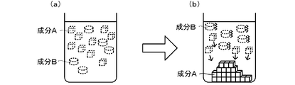
- component A is separated by recrystallization from a mixed solution containing the target compound (component A) and an organic compound other than the target compound (component B) will be described.
- component B an organic compound other than the target compound
- component A When component A is recrystallized directly from the mixture, the infrared absorption of specific functional groups contained in component B that are not contained in component A in the mixture (see FIG. 1A) in which components A and B are dissolved Recrystallization is performed while irradiating with wavelength light (see FIG. 1B, first purification method).
- the dissolved component is indicated by a dotted line
- the crystallized component is indicated by a solid line.
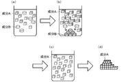
- the mixed solution in which the components A and B are dissolved is included in the component A and included in the component B. Recrystallization is performed while irradiating light having an infrared absorption wavelength of a specific functional group (see FIG. 2 (b), second purification method).
- FIG. 2 also shows dissolved components by dotted lines and crystallized components by solid lines.
- component A is separated by distillation from a mixed solution containing the target compound (component A) and an organic compound other than the target compound (component B) will be described.
- distillation is performed while irradiating the mixed solution with infrared absorption wavelength light of a specific functional group not contained in component A but contained in component B (No. 1). 1 purification method).
- component B is not irradiated with such infrared absorption wavelength light, the vaporization proceeds around the normal boiling point, whereas when irradiated with such infrared absorption wavelength light, the energy state becomes higher, so that the normal boiling point is reached. It is thought that vaporization proceeds at a lower temperature.
- distillation is performed while irradiating the mixed solution with infrared absorption wavelength light of a specific functional group contained in component A but not in component B ( Second purification method).
- component A is not irradiated with such infrared absorption wavelength light
- the vaporization proceeds around the normal boiling point, whereas when irradiated with such infrared absorption wavelength light, the energy state becomes higher, so the normal boiling point is reached. It is thought that vaporization proceeds at a lower temperature.
- infrared light of about 3200 to 3600 cm ⁇ 1 in which OH stretching vibration of water occurs
- water By irradiating only the methanol-water mixture with water, only water selectively absorbs infrared energy. Therefore, compared with the case where it heat-distills by the conventional method without irradiating such infrared light, vaporization of water progresses in a shorter time and at a lower temperature, and methanol can be separated from water.
- component A is separated by column chromatography from a mixed solution containing the target compound (component A) and an organic compound other than the target compound (component B) will be described.
- component B If the elution time of component B is shorter than the elution time of component A, while irradiating the stationary phase of the column with the infrared absorption wavelength light of a specific functional group not contained in component A but contained in component B, Components A and B are passed through the stationary phase together with the mobile phase (first purification method).
- the component B is eluted earlier because it is considered that the affinity with the stationary phase is reduced when irradiated with light that is not irradiated with such infrared absorption wavelength light.
- component A is eluted with the same elution time regardless of the presence or absence of irradiation because the affinity with the stationary phase does not change depending on the presence or absence of irradiation with such infrared absorption wavelength light.
- the difference in elution time between component A and component B is widened, and both can be separated with high accuracy.
- component A is shorter than the elution time of component B, while irradiating the stationary phase of the column with infrared absorption wavelength light of a specific functional group contained in component A but not contained in component B , Components A and B are passed through the stationary phase together with the mobile phase (second purification method).
- the component A is eluted earlier because it is considered that the affinity with the stationary phase is reduced when irradiated with light having no infrared absorption wavelength light.
- component B is eluted with the same elution time regardless of the presence or absence of irradiation because the affinity with the stationary phase does not change depending on the presence or absence of irradiation with such infrared absorption wavelength light.
- the difference in elution time between component A and component B is widened, and both can be separated with high accuracy.
- component A is an alcohol compound having no ketone group
- component B is a ketone compound having no hydroxy group
- a specific functional group not contained in component A but contained in component B is a ketone group
- C You may irradiate the infrared absorption wavelength light of O stretching vibration.
- a specific functional group contained in Component A but not in Component B is a hydroxy group, and irradiated with infrared absorption wavelength light of OH stretching vibration, CO stretching vibration or OH bending vibration. May be.
- Crystalline polymorphs are important in solid pharmaceuticals, and the solubility, bioavailability, and stability differ between each crystal polymorph.
- the reason why crystal polymorphism occurs is that crystallization occurs in different energy states at the stage of crystal precipitation from the solution.
- a target wavelength is obtained from a structure in which a metal pattern, a dielectric layer, and a metal substrate are laminated in this order from the outside to the inside. It is preferable to use an infrared heater that emits infrared light having a peak.
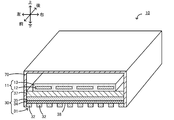
- FIG. 3 is a perspective view of the infrared heater 10, and a part thereof is shown in cross section.
- FIG. 4 is a partial bottom view of the infrared heater 10. The left-right direction, the front-rear direction, and the up-down direction are as shown in FIG.
- the infrared heater 10 includes a heater body 11, a structure 30, and a casing 70.
- the infrared heater 10 radiates infrared rays toward an object (not shown) disposed below.
- the heater body 11 is configured as a so-called planar heater, and includes a heating element 12 in which a linear member is bent in a zigzag manner, and a protective member that is an insulator that contacts the heating element 12 and covers the periphery of the heating element 12. 13.
- Examples of the material of the heating element 12 include W, Mo, Ta, Fe—Cr—Al alloy and Ni—Cr alloy.
- Examples of the material of the protection member 13 include insulating resins such as polyimide, ceramics, and the like.
- the heater body 11 is disposed inside the casing 70. Both ends of the heating element 12 are respectively connected to a pair of input terminals (not shown) attached to the casing 70. Electric power can be supplied to the heating element 12 from the outside through the pair of input terminals.
- the heater body 11 may be a planar heater having a configuration in which a ribbon-like heating element is wound around an insulator.
- the structure 30 is a plate-like member disposed below the heating element 12.
- a first conductor layer 31, a dielectric layer 34, a second conductor layer 35, and a support substrate 37 are laminated in this order from the lower outer side to the inner side of the infrared heater 10.
- the structure 30 is disposed so as to close the opening below the casing 70.
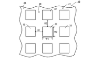
- the first conductor layer 31 is configured as a metal pattern having a periodic structure in which metal electrodes 32 having the same shape and the same size are arranged on the dielectric layer 34 at equal intervals.
- the first conductor layer 31 includes a plurality of rectangular metal electrodes 32 arranged on the dielectric layer 34 at equal intervals in the left-right direction and spaced apart from each other by D2 in the front-rear direction. It is configured as metal patterns that are spaced apart and equidistant from each other.
- the metal electrode 32 has a shape in which the thickness (vertical height) is smaller than the horizontal width W1 (width in the left-right direction) and the vertical width W2 (width in the front-rear direction).
- D1 and D2 are equal, and W1 and W2 are equal.
- Examples of the material of the metal electrode 32 include gold and aluminum (Al).
- the metal electrode 32 is bonded to the dielectric layer 34 via an adhesive layer (not shown).
- Examples of the material for the adhesive layer include chromium (Cr), titanium (Ti), and ruthenium (Ru).
- the dielectric layer 34 is a flat plate member whose upper surface is bonded to the second conductor layer 35.
- the dielectric layer 34 is sandwiched between the first conductor layer 31 and the second conductor layer 35.
- a portion of the lower surface of the dielectric layer 34 where the metal electrode 32 is not disposed is a radiation surface 38 that emits infrared rays to the object.
- Examples of the material of the dielectric layer 34 include alumina (Al 2 O 3 ) and silica (SiO 2 ).
- the second conductor layer 35 is a metal plate whose upper surface is bonded to the support substrate 37 via an adhesive layer (not shown).
- the material of the second conductor layer 35 can be the same material as that of the first conductor layer 31.
- Examples of the material for the adhesive layer include chromium (Cr), titanium (Ti), and ruthenium (Ru).
- the support substrate 37 is a flat member fixed to the inside of the casing 70 by a fixing tool (not shown), and supports the first conductor layer 31, the dielectric layer 34, and the second conductor layer 35.
- Examples of the material of the support substrate 37 include materials that can easily maintain a smooth surface, have high heat resistance, and have low thermal warpage, such as Si wafer and glass.
- the support substrate 37 may be in contact with the lower surface of the heater body 11 or may be disposed apart from the upper and lower sides through a space without contact. When the support substrate 37 and the heater body 11 are in contact with each other, they may be joined.
- Such a structure 30 functions as a metamaterial emitter having a characteristic of selectively emitting infrared rays having a specific wavelength. This characteristic is thought to be due to the resonance phenomenon explained by Magnetic Polariton.
- the magnetic polariton is a resonance phenomenon in which a strong electromagnetic field confinement effect is obtained in a dielectric (dielectric layer 34) between two upper and lower conductors (first conductor layer 31 and second conductor layer 35). is there. Thereby, in the structure 30, a portion of the dielectric layer 34 sandwiched between the second conductor layer 35 and the metal electrode 32 becomes an infrared radiation source.
- the infrared rays emitted from the radiation source enter the metal electrode 32 and are radiated from the portion of the dielectric layer 34 where the metal electrode 32 is not disposed (that is, the radiation surface 38) to the surrounding environment.
- the resonance wavelength can be adjusted by adjusting the material of the first conductor layer 31, the dielectric layer 34, and the second conductor layer 35, and the shape and periodic structure of the first conductor layer 31. Can do.
- the infrared rays radiated from the radiation surface 38 of the structure 30 exhibit a characteristic that the emissivity of infrared rays having a specific wavelength is increased.
- the half width of the structure 30 is 1.5 ⁇ m or less (preferably 1.
- the structure 30 has a characteristic of emitting infrared rays having a steep maximum peak having a relatively small half width and a relatively high emissivity.
- such a structure 30 can be manufactured as follows, for example. First, an adhesive layer (not shown) and the second conductor layer 35 are formed in this order on the surface of the support substrate 37 (lower surface in FIG. 3) by sputtering. Next, the dielectric layer 34 is formed on the surface of the second conductor layer 35 (the lower surface in FIG. 3) by the ALD method (atomic layer deposition method). Subsequently, a predetermined resist pattern is formed on the surface of the dielectric layer 34 (the lower surface in FIG. 3), and then an adhesive layer (not shown) and a layer made of the material of the first conductor layer 31 are sequentially formed by the helicon sputtering method. To do. Then, the first conductor layer 31 (a plurality of metal electrodes 32) is formed by removing the resist pattern.
- ALD method atomic layer deposition method
- the casing 70 has a substantially rectangular parallelepiped shape with a space inside and a bottom surface opened. In the space inside the casing 70, the heater body 11 and the structure 30 are arranged.
- the casing 70 is made of metal (for example, SUS or aluminum) so as to reflect infrared rays emitted from the heating element 12.
- the infrared heater 10 An example of using the infrared heater 10 will be described below.
- power is supplied to both ends of the heating element 12 from a power source (not shown) via an input terminal.
- the power is supplied so that the temperature of the heating element 12 becomes a preset temperature (not particularly limited, but 350 ° C. here).
- the structure 30 is heated.
- the structure 30 rises to a predetermined temperature, becomes a secondary radiator, and emits infrared rays.
- the infrared heater 10 emits infrared rays based on predetermined radiation characteristics.
- FIG. 5 is a graph showing an example of radiation characteristics of infrared rays radiated from the radiation surface 38.
- Curves a to d shown in FIG. 5 are graphs of measured values obtained by measuring the emissivity of infrared rays from the radiation surface 38 when the horizontal width W1 and the vertical width W2 of the metal electrode 32 are changed.
- the emissivity was measured as follows. First, the reflectance of the normal incidence hemisphere of infrared rays from the radiation surface 38 was measured with an FT-IR (Fourier transform infrared spectrometer) having an integrating sphere.
- FT-IR Fastier transform infrared spectrometer
- the first conductor layer 31 and the second conductor layer 35 are gold, the dielectric layer 34 is alumina, the thickness of the first conductor layer 31 is 100 ⁇ m, and the distance D1 and the distance D2 Is 1.50 ⁇ m, the thickness of the dielectric layer 34 is 120 ⁇ m, and the temperature of the structure 30 is 200 ° C.
- W1 vertical width W2
- the peak wavelength shifts to the longer wavelength side as the width of the metal electrode 32 increases from 1.65 ⁇ m to 1.85 ⁇ m.
- Table 1 shows the calculated and measured values of the peak wavelength. The calculated value was the theoretically predicted value of the resonance wavelength based on the LC circuit model. From Table 1, the calculated values and the measured values were in good agreement.
- the width of the metal electrode 32 was manufactured in increments of 0.05 ⁇ m, the peak wavelength was generated in increments of several commas. Therefore, the peak wavelength can be accurately adjusted to the target wavelength. If the width of the metal electrode 32 is designed in increments of 0.01 ⁇ m, it is predicted that the peak wavelength can be generated in increments of several tens of nm. In that case, the peak wavelength can be accurately adjusted according to the target wavelength.
- the infrared heater 10 described above is designed to mainly emit infrared rays having a target wavelength, it is difficult to exclude all radiations other than the target wavelength in the infrared radiation of the structure 30.
- convective heat dissipation from the heater parts to the surroundings is also predicted. Therefore, when configuring an actual process, various considerations should be made on the apparatus shape and the like so that the temperature of the raw materials and the like does not rise excessively due to such accompanying heat flow.
- the target compound is selectively supplied with energy, vaporization progresses at a temperature lower than the normal boiling point, and thermal motion becomes active, resulting in crystallization. Or the affinity with the stationary phase used for chromatography is reduced. By utilizing such a change in characteristics, the target compound and an organic compound other than the target compound can be easily isolated with high purity compared to conventional methods.
- an infrared heater 10 that emits infrared light having a peak at a specific wavelength from the structure 30 that has absorbed energy from the heating element 12 is used.
- This infrared heater 10 can be designed so that the peak wavelength of the radiated infrared ray matches the target wavelength (infrared absorption wavelength light of a specific functional group) with high accuracy.
- the first conductor layer 31 is configured as a metal pattern having a periodic structure in which metal electrodes 32 having the same shape and the same size are arranged at equal intervals.
- the peak wavelength of infrared rays to be radiated changes according to the width W 1 and the width W 2 of the metal electrode 32.
- the horizontal width W1 and the vertical width W2 of the metal electrode 32 can be accurately made as designed values by drawing and lift-off using, for example, a known electron beam drawing apparatus. Therefore, the operation of matching the peak wavelength of the infrared light emitted from the infrared heater 10 with the target wavelength can be performed relatively easily and accurately.
- the target wavelength is set in the range of the wavelength of 0.9 ⁇ m or more and 25 ⁇ m or less (preferably the wavelength of 2.5 ⁇ m or more and 25 ⁇ m or less (4000 to 400 cm ⁇ 1 )), the measurement range of the normal infrared absorption spectrum is Can be covered.
- recrystallization, distillation, and column chromatography are exemplified as the purification method, but the present invention is not particularly limited thereto, and the purification method of the present invention may be applied to extraction, for example.
- the metal electrode 32 has a rectangular shape, but is not limited thereto.
- the metal electrode 32 may have a circular shape or a cross shape (a shape in which rectangles intersect vertically).
- the diameter of the circle corresponds to the horizontal width W1 and the vertical width W2.
- the metal electrode 32 has a cross shape, the lengths of the long sides of the two intersecting rectangles correspond to the horizontal width W1 and the vertical width W2.
- the metal electrodes 32 are arranged in a lattice pattern at equal intervals along the left-right direction and the front-rear direction, the present invention is not limited to this.
- the metal electrodes 32 may be arranged at equal intervals only in the left-right direction or only in the front-rear direction.
- the structure 30 includes the support substrate 37, but the support substrate 37 may be omitted.
- the first conductor layer 31 and the dielectric layer 34 may be directly joined without an adhesive layer, and the second conductor layer 35 and the support substrate 37 do not have an adhesive layer. It may be directly joined to.
- Example 1 500 mL of 50 vol% methanol aqueous solution and boiling stone were added to the distillation apparatus, and atmospheric distillation was performed. Distillation apparatus was heated to 85 ° C., further irradiated from the flask top of infrared 2950 ⁇ 3050 cm -1 with a peak at 3000 cm -1, including a methanol solution of the distillation apparatus (5W: Infrared irradiation area 3cm angle / per unit area Irradiation energy: about 0.5 W / cm 2 ) was started, and the distillation operation was performed while continuing the irradiation. The amount of distillate (methanol concentrate) was measured 5 minutes, 10 minutes and 20 minutes after the start of distillation. The wavelength range of the irradiated infrared rays is a wavelength range where methanol C—H stretching vibration or C—H bending vibration occurs. The results are shown in Table 2.
- Example 2 Of Example 1, infrared radiation of 1030 ⁇ 1130 cm -1 with a peak irradiation conditions of infrared 1080 cm -1 (5W: Infrared irradiation area 3cm angle / unit irradiation energy per unit area: about 0.5 W / cm 2 The amount of distillate (methanol concentrate) after 5 minutes, 10 minutes, and 20 minutes from the start of distillation was measured.
- the wavelength range of the irradiated infrared rays is a wavelength range where the CO stretching vibration of methanol occurs. The results are shown in Table 2.
- Example 2 was irradiated for infrared 1030 ⁇ 1130 cm -1 having a peak at 1080 cm -1
- Comparative Example 1 in which any infrared irradiation was not performed, it was confirmed that the distillation progressed faster in Examples 1 and 2 where irradiation was performed. From this result, it was shown that by performing distillation while irradiating infrared rays in the infrared absorption wavelength region of methanol, a distillate can be obtained at a higher speed than when such irradiation is not performed.
- the methanol concentration in the distillate was 80 to 85% in all cases.
- Example 3 500 mL of 50 vol% methanol aqueous solution and boiling stone were added to the distillation apparatus, and atmospheric distillation was performed.
- the distillation apparatus was heated to 35 ° C. and further irradiated with infrared rays of 1650 to 1750 cm ⁇ 1 having a peak at 1700 cm ⁇ 1 from the top of the flask containing the methanol aqueous solution (5 W: infrared irradiation area 3 cm square / per unit area).
- Irradiation energy about 0.5 W / cm 2
- the amount of distillate was measured 5 minutes, 10 minutes and 20 minutes after the start of distillation. It was confirmed that the composition of the distillate was almost water (95 vol% or more).
- the wavelength range of the irradiated infrared light is a wavelength range where water HO-H bending oscillation occurs. The results are shown in Table 3.
- Example 3 in which infrared irradiation of 1650 to 1750 cm ⁇ 1 having a peak at 1700 cm ⁇ 1 was performed, water was selectively vaporized by irradiation.
- Example 4 0.042 mol of 1,4-dibromobenzene (10.0 g: manufactured by Tokyo Chemical Industry Co., Ltd.) and 0.042 mol of p-aminobenzoic acid (5.8 g: manufactured by Tokyo Chemical Industry Co., Ltd.) were added to 25 mL of ethanol (99 0.5%) (manufactured by Kanto Chemical Co., Inc.) was added to a flask with a cooling tube and heated to 60 ° C. to dissolve the added reagent.
- the wavelength range of the irradiated infrared rays is a wavelength range where C ⁇ C stretching vibration of the aromatic ring of p-aminobenzoic acid and C ⁇ O stretching vibration of the carboxylic acid occur.
- Example 4 and Comparative Example 3 Each crystal precipitated in Example 4 and Comparative Example 3 was collected, washed in order of cold ethanol (4 ° C.), pure water (4 ° C.), and cold ethanol (4 ° C.), and dried. Each sample was subjected to NMR measurement, and the mol% of 1,4-dibromobenzene and p-aminobenzoic acid in the precipitated crystal was calculated from the result of the integration ratio of the signal of the spectrum. The results are shown in Table 4.
- Example 4 in which 6 to 6.5 ⁇ m infrared irradiation having a peak at 6.25 ⁇ m was irradiated and Comparative Example 3 in which no infrared irradiation was performed were more in Example 4. It was confirmed that 1,4-dibromobenzene could be selectively recrystallized. From this result, by irradiating 6 to 6.5 ⁇ m of infrared rays, absorption peculiar to p-aminobenzoic acid occurs, recrystallization of p-aminobenzoic acid is suppressed, and 1,4-dibromobenzene crystals It has been shown that it can be advantageous.
- the present invention can be used when purifying organic compounds.
Landscapes
- Chemical & Material Sciences (AREA)
- Organic Chemistry (AREA)
- Chemical Kinetics & Catalysis (AREA)
- Physics & Mathematics (AREA)
- Health & Medical Sciences (AREA)
- Toxicology (AREA)
- Thermal Sciences (AREA)
- General Health & Medical Sciences (AREA)
- Electromagnetism (AREA)
- Analytical Chemistry (AREA)
- Crystallography & Structural Chemistry (AREA)
- Organic Low-Molecular-Weight Compounds And Preparation Thereof (AREA)
- Physical Or Chemical Processes And Apparatus (AREA)
- Resistance Heating (AREA)
- Vaporization, Distillation, Condensation, Sublimation, And Cold Traps (AREA)
- Investigating Or Analysing Materials By Optical Means (AREA)
Priority Applications (3)
| Application Number | Priority Date | Filing Date | Title |
|---|---|---|---|
| EP17841527.9A EP3501636B1 (en) | 2016-08-19 | 2017-08-16 | Method for refining organic compound |
| JP2017562387A JP6285619B1 (ja) | 2016-08-19 | 2017-08-16 | 有機化合物の精製方法 |
| US16/275,547 US10703697B2 (en) | 2016-08-19 | 2019-02-14 | Method for refining organic compound |
Applications Claiming Priority (2)
| Application Number | Priority Date | Filing Date | Title |
|---|---|---|---|
| JP2016161435 | 2016-08-19 | ||
| JP2016-161435 | 2016-08-19 |
Related Child Applications (1)
| Application Number | Title | Priority Date | Filing Date |
|---|---|---|---|
| US16/275,547 Continuation US10703697B2 (en) | 2016-08-19 | 2019-02-14 | Method for refining organic compound |
Publications (1)
| Publication Number | Publication Date |
|---|---|
| WO2018034305A1 true WO2018034305A1 (ja) | 2018-02-22 |
Family
ID=61196774
Family Applications (1)
| Application Number | Title | Priority Date | Filing Date |
|---|---|---|---|
| PCT/JP2017/029450 Ceased WO2018034305A1 (ja) | 2016-08-19 | 2017-08-16 | 有機化合物の精製方法 |
Country Status (4)
| Country | Link |
|---|---|
| US (1) | US10703697B2 (enExample) |
| EP (1) | EP3501636B1 (enExample) |
| JP (3) | JP6285619B1 (enExample) |
| WO (1) | WO2018034305A1 (enExample) |
Cited By (3)
| Publication number | Priority date | Publication date | Assignee | Title |
|---|---|---|---|---|
| JPWO2022014397A1 (enExample) * | 2020-07-13 | 2022-01-20 | ||
| JPWO2022013919A1 (enExample) * | 2020-07-13 | 2022-01-20 | ||
| WO2023062715A1 (ja) * | 2021-10-12 | 2023-04-20 | 日本碍子株式会社 | 低アルコール飲料の製法 |
Families Citing this family (1)
| Publication number | Priority date | Publication date | Assignee | Title |
|---|---|---|---|---|
| EP3750863B1 (en) * | 2016-08-03 | 2022-07-06 | NGK Insulators, Ltd. | Reaction product preparation method |
Citations (3)
| Publication number | Priority date | Publication date | Assignee | Title |
|---|---|---|---|---|
| WO2007052778A1 (ja) * | 2005-11-02 | 2007-05-10 | Buhei Kono | 有機物や無機物の反応を促進する方法 |
| JP2011213640A (ja) * | 2010-03-31 | 2011-10-27 | Mitsubishi Chemicals Corp | ビスフェノールaの製造方法 |
| JP2017050254A (ja) * | 2015-09-04 | 2017-03-09 | 国立大学法人北海道大学 | 赤外線ヒーター |
Family Cites Families (12)
| Publication number | Priority date | Publication date | Assignee | Title |
|---|---|---|---|---|
| JP2529409Y2 (ja) * | 1990-11-29 | 1997-03-19 | 株式会社デンコー | 格子状遠赤外線ヒータ |
| GB2260975B (en) * | 1991-10-28 | 1995-07-12 | Chang Shih Chang | The process to recover salt from brine waste water |
| JP2709260B2 (ja) * | 1993-10-15 | 1998-02-04 | 株式会社ダイリン商事 | 遠赤外線輻射方法 |
| US20030196885A1 (en) * | 1999-05-17 | 2003-10-23 | Marchitto Kevin S. | Electromagnetic energy driven separation methods |
| WO2007132930A2 (ja) * | 2006-05-14 | 2007-11-22 | Buhei Kono | マイクロ波の波長を、磁性体によって波長転換するとき、加熱する物質が持つ熱吸収波長と最適温度に合わせて、磁性体を選択し最適温度のなかで波長の領域とその密度を高めて加熱加工、熱処理を行う方法並びに赤外線、遠赤外線エネルギーのトンネル効果の構造を示す。 |
| WO2007141826A1 (ja) * | 2006-05-26 | 2007-12-13 | Nalux Co., Ltd. | 赤外光源 |
| JP2010150086A (ja) * | 2008-12-25 | 2010-07-08 | Tohoku Univ | 結晶化ガラスの製造方法 |
| JP2013013840A (ja) * | 2011-07-01 | 2013-01-24 | Seiko Epson Corp | 流体分離装置、気体分離装置及びそれを用いた検出装置 |
| JP2014189462A (ja) | 2013-03-27 | 2014-10-06 | Osaka Univ | 結晶製造方法、準安定形結晶、医薬の製造方法および医薬 |
| JP6702880B2 (ja) * | 2014-03-19 | 2020-06-03 | ビーエーエスエフ ソシエタス・ヨーロピアBasf Se | 溶液から物質を分離するための方法及びデバイス |
| JP2015198063A (ja) * | 2014-04-03 | 2015-11-09 | 日本碍子株式会社 | 赤外線ヒーター |
| EP3187908A4 (en) * | 2014-08-29 | 2018-05-09 | National Institute for Materials Science | Electromagnetic wave absorbing/radiating material, method for manufacturing same, and infrared source |
-
2017
- 2017-08-16 WO PCT/JP2017/029450 patent/WO2018034305A1/ja not_active Ceased
- 2017-08-16 JP JP2017562387A patent/JP6285619B1/ja active Active
- 2017-08-16 EP EP17841527.9A patent/EP3501636B1/en active Active
-
2018
- 2018-01-31 JP JP2018015132A patent/JP6970031B2/ja active Active
-
2019
- 2019-02-14 US US16/275,547 patent/US10703697B2/en active Active
-
2021
- 2021-10-28 JP JP2021176160A patent/JP7242806B2/ja active Active
Patent Citations (3)
| Publication number | Priority date | Publication date | Assignee | Title |
|---|---|---|---|---|
| WO2007052778A1 (ja) * | 2005-11-02 | 2007-05-10 | Buhei Kono | 有機物や無機物の反応を促進する方法 |
| JP2011213640A (ja) * | 2010-03-31 | 2011-10-27 | Mitsubishi Chemicals Corp | ビスフェノールaの製造方法 |
| JP2017050254A (ja) * | 2015-09-04 | 2017-03-09 | 国立大学法人北海道大学 | 赤外線ヒーター |
Non-Patent Citations (1)
| Title |
|---|
| ATSUSHI SAKURAI: "Metamaterial ni yoru Netsu Fukusha Seigyo [Thermal Radiation Control by Metamaterial]", THE 51ST NATIONAL HEAT TRANSFER SYMPOSIUM; MAY/21-23, 2014; HAMAMATSU, JAPAN, vol. 51, 2014, pages H344, XP009513506 * |
Cited By (18)
| Publication number | Priority date | Publication date | Assignee | Title |
|---|---|---|---|---|
| JP7096956B2 (ja) | 2020-07-13 | 2022-07-06 | 日本碍子株式会社 | 精製方法 |
| JP7096958B2 (ja) | 2020-07-13 | 2022-07-06 | 日本碍子株式会社 | 精製方法 |
| JPWO2022014395A1 (enExample) * | 2020-07-13 | 2022-01-20 | ||
| JPWO2022013919A1 (enExample) * | 2020-07-13 | 2022-01-20 | ||
| WO2022014395A1 (ja) * | 2020-07-13 | 2022-01-20 | 日本碍子株式会社 | 精製方法 |
| WO2022013919A1 (ja) * | 2020-07-13 | 2022-01-20 | 日本碍子株式会社 | 精製方法 |
| WO2022014397A1 (ja) * | 2020-07-13 | 2022-01-20 | 日本碍子株式会社 | 精製方法 |
| JPWO2022014396A1 (enExample) * | 2020-07-13 | 2022-01-20 | ||
| WO2022014396A1 (ja) * | 2020-07-13 | 2022-01-20 | 日本碍子株式会社 | 精製方法 |
| JPWO2022014397A1 (enExample) * | 2020-07-13 | 2022-01-20 | ||
| JP7096957B2 (ja) | 2020-07-13 | 2022-07-06 | 日本碍子株式会社 | 精製方法 |
| JP2022125073A (ja) * | 2020-07-13 | 2022-08-26 | 日本碍子株式会社 | 精製方法 |
| CN115315297A (zh) * | 2020-07-13 | 2022-11-08 | 日本碍子株式会社 | 精制方法 |
| CN115315299A (zh) * | 2020-07-13 | 2022-11-08 | 日本碍子株式会社 | 精制方法 |
| JP7506883B2 (ja) | 2020-07-13 | 2024-06-27 | 日本碍子株式会社 | 精製方法 |
| CN115315299B (zh) * | 2020-07-13 | 2024-06-04 | 日本碍子株式会社 | 精制方法 |
| CN115315297B (zh) * | 2020-07-13 | 2024-06-04 | 日本碍子株式会社 | 精制方法 |
| WO2023062715A1 (ja) * | 2021-10-12 | 2023-04-20 | 日本碍子株式会社 | 低アルコール飲料の製法 |
Also Published As
| Publication number | Publication date |
|---|---|
| JP2022037934A (ja) | 2022-03-09 |
| JP7242806B2 (ja) | 2023-03-20 |
| JP6285619B1 (ja) | 2018-02-28 |
| US20190194101A1 (en) | 2019-06-27 |
| EP3501636B1 (en) | 2023-07-26 |
| EP3501636A1 (en) | 2019-06-26 |
| US10703697B2 (en) | 2020-07-07 |
| JP6970031B2 (ja) | 2021-11-24 |
| JPWO2018034305A1 (ja) | 2018-08-16 |
| EP3501636A4 (en) | 2020-05-06 |
| JP2018111096A (ja) | 2018-07-19 |
Similar Documents
| Publication | Publication Date | Title |
|---|---|---|
| JP7242806B2 (ja) | 有機化合物の精製方法 | |
| JP7096957B2 (ja) | 精製方法 | |
| US10822292B2 (en) | Method for producing reaction product | |
| US8067635B2 (en) | Method for producing tertiary amides of alkylphenyl carboxylic acids | |
| Percec et al. | Helical porous protein mimics self-assembled from amphiphilic dendritic dipeptides | |
| JP2012207008A (ja) | 6,6−(9−フルオレニリデン)−ジ(2−ナフトール)の結晶多形体及びその製造方法 | |
| JP7506883B2 (ja) | 精製方法 | |
| JP5545514B2 (ja) | 液晶材料の精製方法 | |
| JP7146345B2 (ja) | フルオレン骨格を有するアルコール化合物を含む樹脂原料用組成物 | |
| WO2023062715A1 (ja) | 低アルコール飲料の製法 | |
| KR20170063794A (ko) | 투명체의 제조 방법, 투명체 및 비정질체 | |
| CN107074722A (zh) | 三苯基丁烯衍生物的制造方法 | |
| Jha et al. | Conversion of substituted 1-arylidene-2-tetralones to 2-alkoxy-1-arylmethylnaphthalenes: An example of facile aromatization | |
| JP4953274B2 (ja) | 分子回転周期差を利用した同位体の分離方法 | |
| Chang | Investigation of higher fullerenes | |
| Becker et al. | On the Thermal Reversibility of the Photochemical Di-π-methane Rearrangement of Bicyclo [2, 2, 2] octadienones. Confirmation of Regiospecificity and Stereochemistry by X-Ray Structure Analyses | |
| Kunimoto et al. | Polymorphism of 4-fluorophenylpyruvic acid studied by x-ray crystallography and vibrational spectroscopy | |
| Assaad et al. | Powder X-ray study of racemic (2RS, 3RS)-5-amino-3-(4-phenylpiperazin-1-yl)-1, 2, 3, 4-tetrahydronaphthalen-2-ol |
Legal Events
| Date | Code | Title | Description |
|---|---|---|---|
| WWE | Wipo information: entry into national phase |
Ref document number: 2017562387 Country of ref document: JP |
|
| 121 | Ep: the epo has been informed by wipo that ep was designated in this application |
Ref document number: 17841527 Country of ref document: EP Kind code of ref document: A1 |
|
| NENP | Non-entry into the national phase |
Ref country code: DE |
|
| ENP | Entry into the national phase |
Ref document number: 2017841527 Country of ref document: EP Effective date: 20190319 |