EP3501636B1 - Method for refining organic compound - Google Patents
Method for refining organic compound Download PDFInfo
- Publication number
- EP3501636B1 EP3501636B1 EP17841527.9A EP17841527A EP3501636B1 EP 3501636 B1 EP3501636 B1 EP 3501636B1 EP 17841527 A EP17841527 A EP 17841527A EP 3501636 B1 EP3501636 B1 EP 3501636B1
- Authority
- EP
- European Patent Office
- Prior art keywords
- component
- target compound
- infrared
- light
- irradiated
- Prior art date
- Legal status (The legal status is an assumption and is not a legal conclusion. Google has not performed a legal analysis and makes no representation as to the accuracy of the status listed.)
- Active
Links
- 150000002894 organic compounds Chemical class 0.000 title claims description 55
- 238000000034 method Methods 0.000 title claims description 49
- 238000007670 refining Methods 0.000 title claims description 10
- 150000001875 compounds Chemical class 0.000 claims description 58
- 230000005855 radiation Effects 0.000 claims description 47
- 238000010521 absorption reaction Methods 0.000 claims description 44
- 229910052751 metal Inorganic materials 0.000 claims description 40
- 239000002184 metal Substances 0.000 claims description 40
- 125000000524 functional group Chemical group 0.000 claims description 24
- 239000000758 substrate Substances 0.000 claims description 14
- OKKJLVBELUTLKV-UHFFFAOYSA-N Methanol Chemical compound OC OKKJLVBELUTLKV-UHFFFAOYSA-N 0.000 description 60
- 238000004821 distillation Methods 0.000 description 35
- 239000004020 conductor Substances 0.000 description 33
- 239000013078 crystal Substances 0.000 description 22
- 238000009835 boiling Methods 0.000 description 20
- 239000000203 mixture Substances 0.000 description 19
- 239000000463 material Substances 0.000 description 16
- ALYNCZNDIQEVRV-UHFFFAOYSA-N 4-aminobenzoic acid Chemical compound NC1=CC=C(C(O)=O)C=C1 ALYNCZNDIQEVRV-UHFFFAOYSA-N 0.000 description 14
- 238000010438 heat treatment Methods 0.000 description 14
- 230000005526 G1 to G0 transition Effects 0.000 description 12
- 238000001953 recrystallisation Methods 0.000 description 11
- XLYOFNOQVPJJNP-UHFFFAOYSA-N water Substances O XLYOFNOQVPJJNP-UHFFFAOYSA-N 0.000 description 10
- 230000000052 comparative effect Effects 0.000 description 9
- 238000007796 conventional method Methods 0.000 description 9
- LFQSCWFLJHTTHZ-UHFFFAOYSA-N Ethanol Chemical compound CCO LFQSCWFLJHTTHZ-UHFFFAOYSA-N 0.000 description 8
- 238000010828 elution Methods 0.000 description 8
- 238000009834 vaporization Methods 0.000 description 8
- 230000008016 vaporization Effects 0.000 description 8
- 229960004050 aminobenzoic acid Drugs 0.000 description 7
- 238000002425 crystallisation Methods 0.000 description 7
- 230000008025 crystallization Effects 0.000 description 7
- 239000000706 filtrate Substances 0.000 description 7
- 238000004587 chromatography analysis Methods 0.000 description 6
- 238000005259 measurement Methods 0.000 description 6
- SWJPEBQEEAHIGZ-UHFFFAOYSA-N 1,4-dibromobenzene Chemical compound BrC1=CC=C(Br)C=C1 SWJPEBQEEAHIGZ-UHFFFAOYSA-N 0.000 description 5
- 239000000126 substance Substances 0.000 description 5
- IISBACLAFKSPIT-UHFFFAOYSA-N bisphenol A Chemical compound C=1C=C(O)C=CC=1C(C)(C)C1=CC=C(O)C=C1 IISBACLAFKSPIT-UHFFFAOYSA-N 0.000 description 4
- 239000011651 chromium Substances 0.000 description 4
- 238000004440 column chromatography Methods 0.000 description 4
- 230000000737 periodic effect Effects 0.000 description 4
- 239000010936 titanium Substances 0.000 description 4
- -1 alcohol compound Chemical class 0.000 description 3
- PNEYBMLMFCGWSK-UHFFFAOYSA-N aluminium oxide Inorganic materials [O-2].[O-2].[O-2].[Al+3].[Al+3] PNEYBMLMFCGWSK-UHFFFAOYSA-N 0.000 description 3
- 238000000605 extraction Methods 0.000 description 3
- GBMDVOWEEQVZKZ-UHFFFAOYSA-N methanol;hydrate Chemical compound O.OC GBMDVOWEEQVZKZ-UHFFFAOYSA-N 0.000 description 3
- 230000001681 protective effect Effects 0.000 description 3
- VYZAMTAEIAYCRO-UHFFFAOYSA-N Chromium Chemical compound [Cr] VYZAMTAEIAYCRO-UHFFFAOYSA-N 0.000 description 2
- 238000005033 Fourier transform infrared spectroscopy Methods 0.000 description 2
- KJTLSVCANCCWHF-UHFFFAOYSA-N Ruthenium Chemical compound [Ru] KJTLSVCANCCWHF-UHFFFAOYSA-N 0.000 description 2
- RTAQQCXQSZGOHL-UHFFFAOYSA-N Titanium Chemical compound [Ti] RTAQQCXQSZGOHL-UHFFFAOYSA-N 0.000 description 2
- 238000000862 absorption spectrum Methods 0.000 description 2
- 229910052782 aluminium Inorganic materials 0.000 description 2
- XAGFODPZIPBFFR-UHFFFAOYSA-N aluminium Chemical compound [Al] XAGFODPZIPBFFR-UHFFFAOYSA-N 0.000 description 2
- 238000000231 atomic layer deposition Methods 0.000 description 2
- 239000003153 chemical reaction reagent Substances 0.000 description 2
- 229910052804 chromium Inorganic materials 0.000 description 2
- 238000001816 cooling Methods 0.000 description 2
- 230000005670 electromagnetic radiation Effects 0.000 description 2
- 238000001704 evaporation Methods 0.000 description 2
- 230000008020 evaporation Effects 0.000 description 2
- PCHJSUWPFVWCPO-UHFFFAOYSA-N gold Chemical compound [Au] PCHJSUWPFVWCPO-UHFFFAOYSA-N 0.000 description 2
- 229910052737 gold Inorganic materials 0.000 description 2
- 239000010931 gold Substances 0.000 description 2
- 125000002887 hydroxy group Chemical group [H]O* 0.000 description 2
- 239000012535 impurity Substances 0.000 description 2
- 125000000468 ketone group Chemical group 0.000 description 2
- 150000002605 large molecules Chemical class 0.000 description 2
- 229910052707 ruthenium Inorganic materials 0.000 description 2
- 238000000926 separation method Methods 0.000 description 2
- 239000002904 solvent Substances 0.000 description 2
- 238000004544 sputter deposition Methods 0.000 description 2
- 229910052719 titanium Inorganic materials 0.000 description 2
- BSYNRYMUTXBXSQ-UHFFFAOYSA-N Aspirin Chemical compound CC(=O)OC1=CC=CC=C1C(O)=O BSYNRYMUTXBXSQ-UHFFFAOYSA-N 0.000 description 1
- 229910002060 Fe-Cr-Al alloy Inorganic materials 0.000 description 1
- 238000005481 NMR spectroscopy Methods 0.000 description 1
- 229910018487 Ni—Cr Inorganic materials 0.000 description 1
- 239000004642 Polyimide Substances 0.000 description 1
- VYPSYNLAJGMNEJ-UHFFFAOYSA-N Silicium dioxide Chemical compound O=[Si]=O VYPSYNLAJGMNEJ-UHFFFAOYSA-N 0.000 description 1
- 229910045601 alloy Inorganic materials 0.000 description 1
- 239000000956 alloy Substances 0.000 description 1
- 125000003118 aryl group Chemical group 0.000 description 1
- 238000005452 bending Methods 0.000 description 1
- 125000003178 carboxy group Chemical group [H]OC(*)=O 0.000 description 1
- 239000000919 ceramic Substances 0.000 description 1
- 229910052593 corundum Inorganic materials 0.000 description 1
- 239000002178 crystalline material Substances 0.000 description 1
- 238000013461 design Methods 0.000 description 1
- 239000003814 drug Substances 0.000 description 1
- 230000000694 effects Effects 0.000 description 1
- 238000000609 electron-beam lithography Methods 0.000 description 1
- 238000001914 filtration Methods 0.000 description 1
- 239000011521 glass Substances 0.000 description 1
- 230000017525 heat dissipation Effects 0.000 description 1
- 230000001678 irradiating effect Effects 0.000 description 1
- 238000001459 lithography Methods 0.000 description 1
- 229910052750 molybdenum Inorganic materials 0.000 description 1
- 229930014626 natural product Natural products 0.000 description 1
- 239000003960 organic solvent Substances 0.000 description 1
- 229920001721 polyimide Polymers 0.000 description 1
- 239000002244 precipitate Substances 0.000 description 1
- 239000000047 product Substances 0.000 description 1
- 102000004169 proteins and genes Human genes 0.000 description 1
- 108090000623 proteins and genes Proteins 0.000 description 1
- 239000002994 raw material Substances 0.000 description 1
- 230000001105 regulatory effect Effects 0.000 description 1
- 229920005989 resin Polymers 0.000 description 1
- 239000011347 resin Substances 0.000 description 1
- 150000003384 small molecules Chemical class 0.000 description 1
- 239000007787 solid Substances 0.000 description 1
- 238000001228 spectrum Methods 0.000 description 1
- 229920003002 synthetic resin Polymers 0.000 description 1
- 239000000057 synthetic resin Substances 0.000 description 1
- 229910052715 tantalum Inorganic materials 0.000 description 1
- 238000012546 transfer Methods 0.000 description 1
- 238000002834 transmittance Methods 0.000 description 1
- 229910052721 tungsten Inorganic materials 0.000 description 1
- 235000012431 wafers Nutrition 0.000 description 1
- 229910001845 yogo sapphire Inorganic materials 0.000 description 1
Images

Classifications
-
- B—PERFORMING OPERATIONS; TRANSPORTING
- B01—PHYSICAL OR CHEMICAL PROCESSES OR APPARATUS IN GENERAL
- B01D—SEPARATION
- B01D1/00—Evaporating
- B01D1/0011—Heating features
- B01D1/0029—Use of radiation
-
- C—CHEMISTRY; METALLURGY
- C07—ORGANIC CHEMISTRY
- C07C—ACYCLIC OR CARBOCYCLIC COMPOUNDS
- C07C29/00—Preparation of compounds having hydroxy or O-metal groups bound to a carbon atom not belonging to a six-membered aromatic ring
- C07C29/74—Separation; Purification; Use of additives, e.g. for stabilisation
- C07C29/76—Separation; Purification; Use of additives, e.g. for stabilisation by physical treatment
- C07C29/80—Separation; Purification; Use of additives, e.g. for stabilisation by physical treatment by distillation
-
- B—PERFORMING OPERATIONS; TRANSPORTING
- B01—PHYSICAL OR CHEMICAL PROCESSES OR APPARATUS IN GENERAL
- B01D—SEPARATION
- B01D1/00—Evaporating
- B01D1/30—Accessories for evaporators ; Constructional details thereof
-
- B—PERFORMING OPERATIONS; TRANSPORTING
- B01—PHYSICAL OR CHEMICAL PROCESSES OR APPARATUS IN GENERAL
- B01D—SEPARATION
- B01D15/00—Separating processes involving the treatment of liquids with solid sorbents; Apparatus therefor
- B01D15/08—Selective adsorption, e.g. chromatography
- B01D15/26—Selective adsorption, e.g. chromatography characterised by the separation mechanism
- B01D15/38—Selective adsorption, e.g. chromatography characterised by the separation mechanism involving specific interaction not covered by one or more of groups B01D15/265 - B01D15/36
- B01D15/3804—Affinity chromatography
-
- B—PERFORMING OPERATIONS; TRANSPORTING
- B01—PHYSICAL OR CHEMICAL PROCESSES OR APPARATUS IN GENERAL
- B01D—SEPARATION
- B01D15/00—Separating processes involving the treatment of liquids with solid sorbents; Apparatus therefor
- B01D15/08—Selective adsorption, e.g. chromatography
- B01D15/26—Selective adsorption, e.g. chromatography characterised by the separation mechanism
- B01D15/38—Selective adsorption, e.g. chromatography characterised by the separation mechanism involving specific interaction not covered by one or more of groups B01D15/265 - B01D15/36
- B01D15/3861—Selective adsorption, e.g. chromatography characterised by the separation mechanism involving specific interaction not covered by one or more of groups B01D15/265 - B01D15/36 using an external stimulus
- B01D15/3871—Selective adsorption, e.g. chromatography characterised by the separation mechanism involving specific interaction not covered by one or more of groups B01D15/265 - B01D15/36 using an external stimulus using light
-
- B—PERFORMING OPERATIONS; TRANSPORTING
- B01—PHYSICAL OR CHEMICAL PROCESSES OR APPARATUS IN GENERAL
- B01D—SEPARATION
- B01D17/00—Separation of liquids, not provided for elsewhere, e.g. by thermal diffusion
- B01D17/005—Separation of liquids, not provided for elsewhere, e.g. by thermal diffusion by thermal diffusion
-
- B—PERFORMING OPERATIONS; TRANSPORTING
- B01—PHYSICAL OR CHEMICAL PROCESSES OR APPARATUS IN GENERAL
- B01D—SEPARATION
- B01D9/00—Crystallisation
- B01D9/0018—Evaporation of components of the mixture to be separated
- B01D9/0031—Evaporation of components of the mixture to be separated by heating
-
- B—PERFORMING OPERATIONS; TRANSPORTING
- B01—PHYSICAL OR CHEMICAL PROCESSES OR APPARATUS IN GENERAL
- B01J—CHEMICAL OR PHYSICAL PROCESSES, e.g. CATALYSIS OR COLLOID CHEMISTRY; THEIR RELEVANT APPARATUS
- B01J19/00—Chemical, physical or physico-chemical processes in general; Their relevant apparatus
- B01J19/08—Processes employing the direct application of electric or wave energy, or particle radiation; Apparatus therefor
- B01J19/12—Processes employing the direct application of electric or wave energy, or particle radiation; Apparatus therefor employing electromagnetic waves
- B01J19/122—Incoherent waves
- B01J19/128—Infra-red light
-
- C—CHEMISTRY; METALLURGY
- C07—ORGANIC CHEMISTRY
- C07B—GENERAL METHODS OF ORGANIC CHEMISTRY; APPARATUS THEREFOR
- C07B63/00—Purification; Separation; Stabilisation; Use of additives
-
- C—CHEMISTRY; METALLURGY
- C07—ORGANIC CHEMISTRY
- C07C—ACYCLIC OR CARBOCYCLIC COMPOUNDS
- C07C31/00—Saturated compounds having hydroxy or O-metal groups bound to acyclic carbon atoms
- C07C31/02—Monohydroxylic acyclic alcohols
- C07C31/04—Methanol
-
- B—PERFORMING OPERATIONS; TRANSPORTING
- B01—PHYSICAL OR CHEMICAL PROCESSES OR APPARATUS IN GENERAL
- B01D—SEPARATION
- B01D2221/00—Applications of separation devices
- B01D2221/10—Separation devices for use in medical, pharmaceutical or laboratory applications, e.g. separating amalgam from dental treatment residues
-
- B—PERFORMING OPERATIONS; TRANSPORTING
- B01—PHYSICAL OR CHEMICAL PROCESSES OR APPARATUS IN GENERAL
- B01D—SEPARATION
- B01D9/00—Crystallisation
- B01D9/005—Selection of auxiliary, e.g. for control of crystallisation nuclei, of crystal growth, of adherence to walls; Arrangements for introduction thereof
Definitions
- the present invention relates to a method for refining an organic compound.
- PTL 1 discloses a method for refining an organic compound using laser light.
- a material in a metastable form is selectively produced from a solution containing the material that forms stable and metastable crystals
- the solution is irradiated with a laser beam to generate air bubbles, and metastable crystal nuclei are thereby generated, so that the metastable crystals are selectively produced.
- JP 2011-213640-A discloses a method for removing water and an organic solvent from the crystal of bisphenol A comprising irradiating a substantially phenol-free bisphenol A with infrared rays.
- WO 2015/140062 A2 relates to a method for separating a substance out of a solution, wherein electromagnetic radiation is radiated into a solution, and the scattered intensity of the electromagnetic radiation is compared with a desired intensity. The temperature of the solution is then regulated depending on the difference between the detected intensity and the desired intensity to control the separation process.
- the method described in PTL 1 is a method for selectively producing a metastable crystalline material, is not widely applicable to methods for refining organic compounds, and disadvantageously lacks versatility.
- the solution is irradiated with the laser light in order to generate air bubbles in the solution, and no attention is paid to light at an infrared absorption wavelength of the material.
- the present invention has been made to solve the foregoing problem, and it is a principal object to provide a highly versatile method for refining a target organic compound with higher purity in a simpler manner than with conventional methods.
- the organic compound refinement method of the present invention is set out in claim 1.
- the at least two types of organic compounds are irradiated with the light at the infrared absorption wavelength of the specific functional group not contained in the target compound but contained in the organic compound other than the target compound.
- the organic compound since energy is selectively given to the organic compound other than the target compound among the at least two types of organic compounds, the organic compound is vaporized at a temperature lower than its normal boiling point, resists crystallization because of its increased thermal motion, or has reduced affinity for a stationary phase used in chromatography.
- the target compound can be isolated from the organic compound other than the target compound with higher purity in a simpler manner than with conventional methods. This method is applicable to refinement of various organic compounds and is highly versatile.
- the at least two types of organic compounds are irradiated with the light at the infrared absorption wavelength of the specific functional group contained in the target compound but not contained in the organic compound other than the target compound.
- the target compound since energy is selectively given to the target compound, the target compound is vaporized at a temperature lower than its normal boiling point, resists crystallization because of its increased thermal motion, or has reduced affinity for a stationary phase used in chromatography.
- the target compound can be isolated from the organic compound other than the target compound with higher purity in a simpler manner than with conventional methods. This method is applicable to refinement of various organic compounds and is highly versatile.
- the separation method examples include distillation, recrystallization, chromatography, and extraction.
- the organic compounds used in the present invention may be low-molecular weight compounds or may be high-molecular weight compounds.
- the high-molecular weight compounds may be natural products such as proteins or artificial products such as synthetic resins.
- the recrystallization encompasses selective recrystallization of a compound having a specific structure (e.g., a method for selectively crystallizing only specific crystals of a compound that exhibits crystal polymorphism).
- a first refinement method in the present embodiment is a method for refining a specific organic compound which is a target compound from at least two types of organic compounds.
- the method includes separating the target compound from a compound other than the target compound while the at least two types of organic compounds are irradiated with light at an infrared absorption wavelength of a specific functional group that is not contained in the target compound but is contained in the organic compound other than the target compound.
- a second refinement method in the present embodiment is a method for refining a specific organic compound which is a target compound from at least two types of organic compounds.
- the method includes separating the target compound from a compound other than the target compound while the at least two types of organic compounds are irradiated with light at an infrared absorption wavelength of a specific functional group that is contained in the target compound but is not contained in the organic compound other than the target compound.
- a component A is separated from a solution mixture containing a target compound (the component A) and an organic compound (a component B) other than the target compound. It is assumed that both the components A and B form crystals.
- the recrystallization is performed while the solution mixture containing the components A and B dissolved therein (see Fig. 1(a) ) is irradiated with light at an infrared absorption wavelength of a specific functional group that is not contained in the component A but is contained in the component B (see Fig. 1(b) , the first refinement method).
- dissolved components are indicated by dotted lines
- a crystallized component is indicated by solid lines.
- the thermal motion of molecules of the component B is assumed to be more vigorous when the component B is irradiated with the light at the infrared absorption wavelength than when the component B is not irradiated.
- the solution containing the components A and B dissolved therein is cooled in the course of recrystallization, the component A whose molecules are not undergoing vigorous thermal motion is first crystallized, and crystallization of the component B whose molecules are undergoing vigorous thermal motion is suppressed.
- the number of recrystallization operations necessary to obtain the component A with high purity can be lower than in conventional methods.
- the component B whose molecules are not undergoing vigorous thermal motion is first crystallized, and crystallization of the component A whose molecules are undergoing vigorous thermal motion is suppressed. Then the crystallized component B is removed by filtration, and a filtrate containing the component A at a high concentration is thereby obtained (see Fig. 2(c) ). Then the solvent in the filtrate is removed by evaporation, and the component A can thereby be obtained with high purity (see Fig. 2(d) ). Instead of removing the solvent in the filtrate by evaporation, the component A may be recrystallized from the filtrate.
- the distillation is performed while the solution mixture is irradiated with light at an infrared absorption wavelength of a specific functional group that is not contained in the component A but is contained in the component B (the first refinement method).
- Vaporization of the component B proceeds at around its normal boiling point when the component B is not irradiated with the light at the infrared absorption wavelength.
- the energy state of the component B increases, and therefore the vaporization of the component B may proceed at a temperature lower than its normal boiling point.
- the distillation is performed while the solution mixture is irradiated with light at an infrared absorption wavelength of a specific functional group that is contained in the component A but is not contained in the component B (the second refinement method).
- Vaporization of the component A proceeds at around its normal boiling point when the component A is not irradiated with the light at the infrared absorption wavelength.
- the energy state of the component A increases, and therefore the vaporization of the component A may proceed at a temperature lower than its normal boiling point.
- the methanol-water solution mixture is irradiated only with infrared light of about 2,700 to about 3,000 cm -1 at which O-H stretching vibrations of water do not occur but O-H stretching vibrations, C-H stretching vibrations, or C-H deformation vibration of methanol occur, only methanol absorbs infrared energy selectively. Therefore, the vaporization of methanol proceeds at a lower temperature in a shorter time than when the mixture is not irradiated with the infrared light and is heated and distilled using a conventional method, and the methanol and water can thereby be separated from each other.
- the methanol-water solution mixture When the methanol-water solution mixture is irradiated only with infrared light in a wavenumber range in which absorption of the infrared light by methanol does not occur and which is selected from about 3,200 to about 3,600 cm -1 where O-H stretching vibrations occur or with infrared light of about 1,600 to about 1,800 cm -1 where O-H deformation vibrations occur, only water absorbs infrared energy selectively. Therefore, the vaporization of water proceeds at a lower temperature in a shorter time than when the mixture is not irradiated with the infrared light and is heated and distilled using a conventional method, and the methanol and water can thereby be separated from each other.
- the components A and B, together with the mobile phase are caused to pass through the stationary phase while the stationary phase in the column is irradiated with light at an infrared absorption wavelength of a specific functional group that is not contained in the component A but is contained in the component B (the first refinement method). Since the affinity of the component B for the stationary phase when the component B is irradiated with the light at the infrared absorption wavelength can be considered to be lower than when the component B is not irradiated, the component B is eluted faster.
- the affinity of the component A for the stationary phase does not change irrespective of whether the component A is irradiated with the light at the infrared absorption wavelength
- the elution time of the component A is unchanged irrespective of whether the component A is irradiated. Therefore, when the component A and the component B are separated from each other by column chromatography under irradiation with the light at the infrared absorption wavelength, the difference in elution time between the component A and the component B increases, and they can be separated from each other with high accuracy.
- the components A and B, together with the mobile phase are caused to pass through the stationary phase while the stationary phase in the column is irradiated with light at an infrared absorption wavelength of a specific functional group that is contained in the component A but is not contained in the component B (the second refinement method). Since the affinity of the component A for the stationary phase when the component A is irradiated with the light at the infrared absorption wavelength can be considered to be lower than when the component A is not irradiated, the component A is eluted faster.
- the affinity of the component B for the stationary phase does not change irrespective of whether the component B is irradiated with the light at the infrared absorption wavelength
- the elution time of the component B is unchanged irrespective of whether the component B is irradiated. Therefore, when the component A and the component B are separated from each other by column chromatography under irradiation with the light at the infrared absorption wavelength, the difference in elution time between the component A and the component B increases, and they can be separated from each other with high accuracy.
- the component A is an alcohol compound having no ketone group and the component B is a ketone compound having no hydroxy group
- the specific functional group that is contained in the component A but is not contained in the component B may be a hydroxy group, and the solution mixture may be irradiated with light at the infrared absorption wavelength of O-H stretching vibrations, C-O stretching vibrations, or O-H deformation vibrations.
- the above-described principle is applicable to a compound that exhibits crystal polymorphism that is the ability of molecules of the compound in the form of crystals to have different molecular arrangements, and only a specific crystal structure can be obtained.
- the crystal polymorphism is important for solid pharmaceuticals, and different polymorphic crystal structures differ in solubility, bioavailability, and stability. The reason that the crystal polymorphism occurs is that, when crystals precipitate from a solution, their crystallization occurs in different energy states.
- the target crystal structure can be selectively crystallized and can be obtained at a higher yield in a simpler manner than with conventional methods.
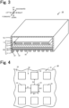
- an infrared heater is used, the infrared heater being configured to emit infrared radiation having a peak at a target wavelength from a structural member including a metal pattern, a dielectric layer, and a metal substrate that are stacked in this order from the outside toward the inside.
- Fig. 3 is a perspective view, partially in cross section, of the infrared heater 10.
- Fig. 4 is a partial bottom view of the infrared heater 10. Left and right directions, front and rear directions, and upward and downward directions are as shown in Fig. 3 .
- the infrared heater 10 includes a heater main body 11, a structural member 30, and a casing 70.
- the infrared heater 10 emits infrared radiation toward an unillustrated target disposed below the infrared heater 10.
- the heater main body 11 is formed as a so-called planer heater and includes: a heating element 12 prepared by bending a linear member into a zigzag pattern; and a protective member 13 that is in contact with the heating element 12 and surrounds the heating element 12.
- Examples of the material of the heating element 12 include W, Mo, Ta, Fe-Cr-Al alloys, and Ni-Cr alloys.
- Examples of the material of the protective member 13 include insulating resins such as polyimide and ceramics.
- the heater main body 11 is disposed inside the casing 70. Opposite ends of the heating element 12 are connected a pair of unillustrated input terminals attached to the casing 70. Electric power can be supplied from the outside to the heating element 12 through the pair of input terminals.
- the heater main body 11 may be a planar heater having a structure including an insulating member and a ribbon-shaped heating element wound around the insulating member.
- the structural member 30 is a plate-shaped member disposed below the heating element 12.
- the structural member 30 includes a first conductor layer 31, a dielectric layer 34, a second conductor layer 35, and a support substrate 37 that are stacked in this order from the outer lower side of the infrared heater 10 toward its inner side.
- the structural member 30 is disposed so as to block a lower opening of the casing 70.
- the first conductor layer 31 is formed as a metal pattern having a periodic structure including metal electrodes 32 having the same shape and the same size and arranged at regular intervals on the dielectric layer 34.
- the first conductor layer 31 is formed as the metal pattern including a plurality of quadrangular metal electrodes 32 disposed on the dielectric layer 34 at regular intervals D1 in the left-right direction and at regular intervals D2 in the front-rear direction.
- the metal electrodes 32 each have a shape having a thickness (a vertical height) smaller than its lateral width W1 (the width in the left-right direction) and its longitudinal width W2 (the width in the front-rear direction).
- Examples of the material of the metal electrodes 32 include gold and aluminum (Al).
- the metal electrodes 32 are joined to the dielectric layer 34 through an unillustrated bonding layer. Examples of the material of the bonding layer include chromium (Cr), titanium (Ti), and ruthenium (Ru).
- the dielectric layer 34 is a plate-shaped member having an upper surface joined to the second conductor layer 35.
- the dielectric layer 34 is held between the first conductor layer 31 and the second conductor layer 35.
- a portion of the lower surface of the dielectric layer 34 on which portion no metal electrodes 32 are disposed serves as an emission surface 38 that emits infrared radiation toward a target.
- Examples of the material of the dielectric layer 34 include alumina (Al 2 O 3 ) and silica (SiO 2 ).
- the second conductor layer 35 is a metal plate having an upper surface joined to the support substrate 37 through an unillustrated bonding layer.
- the material of the second conductor layer 35 may be the same as the material of the first conductor layer 31.
- Examples of the material of the bonding layer include chromium (Cr), titanium (Ti), and ruthenium (Ru).
- the support substrate 37 is a plate-shaped member fixed inside the casing 70 with an unillustrated fixture and supports the first conductor layer 31, the dielectric layer 34, and the second conductor layer 35.
- Examples of the material of the support substrate 37 include materials such as Si wafers and glass that can easily maintain a smooth surface, have high heat resistance, and resist heat warpage.
- the support substrate 37 may be in contact with the lower surface of the heater main body 11 or may not be in contact with the heater main body 11 and may be disposed so as to be vertically separated from the heater main body 11 with a space therebetween. When the support substrate 37 is in contact with the heater main body 11, they may be joined together.
- This structural member 30 functions as a metamaterial emitter having the characteristic that infrared radiation having a specific wavelength is selectively emitted. This characteristic is considered to be due to a resonance phenomenon described by magnetic polaritons.
- the magnetic polaritons means a resonance phenomenon in which a strong electromagnetic wave confinement effect is obtained in a dielectric (the dielectric layer 34) between two upper and lower conductors (the first conductor layer 31 and the second conductor layer 35). Therefore, in the structural member 30, portions of the dielectric layer 34 that are held between the second conductor layer 35 and the metal electrodes 32 serve as infrared emission sources.
- the infrared radiation emitted from the emission sources travels along the metal electrodes 32 and is then emitted to the ambient environment through the portion of the dielectric layer 34 on which no metal electrodes 32 are disposed (i.e., the emission surface 38).
- the resonance wavelength can be controlled by adjusting the materials of the first conductor layer 31, the dielectric layer 34, and the second conductor layer 35 and the shape and periodic structure of the first conductor layer 31. Therefore, the infrared radiation emitted from the emission surface 38 of the structural member 30 has the characteristic that the emissivity of infrared radiation is high at a specific wavelength.
- the materials, the shape, and the periodic structure described above are adjusted such that the structural member 30 has the characteristic that infrared radiation having a maximum peak with a half-width of 1.5 ⁇ m or less (preferably 1.0 ⁇ m or less) and an emissivity of 0.7 or more (preferably 0.8 or more) in a wavelength range of from 2.5 ⁇ m to 25 ⁇ m inclusive (4000 to 400 cm -1 ) is emitted from the emission surface 38 (this characteristic is hereinafter referred to simple as a "prescribed emission characteristic").
- the structural member 30 has the characteristic that infrared radiation having a steep maximum peak with a relatively small half-width and a relatively large emissivity is emitted.
- the structural member 30 can be produced, for example, as follows. First, a bonding layer (not shown) and the second conductor layer 35 are formed in this order on a surface (the lower surface in Fig. 3 ) of the support substrate 37 by sputtering. Next, the dielectric layer 34 is formed on a surface (the lower surface in Fig. 3 ) of the second conductor layer 35 by an ALD method (atomic layer deposition method). Then a prescribed resist pattern is formed on a surface (the lower surface in Fig. 3 ) of the dielectric layer 34, and a bonding layer (not shown) and a layer made of the material of the first conductor layer 31 are sequentially formed by a helicon sputtering method. Then the resist pattern is removed, and the first conductor layer 31 (the plurality of metal electrodes 32) is thereby formed.
- ALD method atomic layer deposition method
- the casing 70 has a substantially cuboidal shape having an inner space and an open bottom.
- the heater main body 11 and the structural member 30 are disposed in the inner space of the casing 70.
- the casing 70 is made of a metal (e.g., SUS or aluminum) so that the infrared radiation emitted from the heating element 12 is reflected.
- the infrared heater 10 An example of the use of the infrared heater 10 will be described.
- electric power is supplied from an unillustrated power source to the opposite ends of the heating element 12 through the input terminals.
- the electric power is supplied such that the temperature of the heating element 12 reaches a preset temperature (350°C in this case, but the temperature is not particularly limited to 350°C).
- Energy is transferred from the heating element 12 heated to the preset temperature to its surroundings through at least one of three forms of heat transfer, i.e., conduction, convection and radiation, and the structural member 30 is thereby heated. Therefore, the structural member 30 is heated to a prescribed temperature, serves as a secondary radiator, and emits infrared radiation.
- the structural member 30 includes the first conductor layer 31, the dielectric layer 34, and the second conductor layer 35 as described above, the infrared heater 10 emits infrared radiation based on the prescribed emission characteristic.
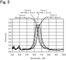
- Fig. 5 is a graph showing examples of the emission characteristic of the infrared radiation emitted from the emission surface 38. Curves a to d shown in the graph in Fig. 5 show measurements of the emissivity of the infrared radiation emitted from the emission surface 38 when different lateral widths W1 and different longitudinal widths W2 of the metal electrodes 32 were used. The emissivity was measured as follows. First, the normal incidence hemispherical reflectance for the infrared radiation from the emission surface 38 was measured using an FT-IR (Fourier transform infrared spectrometer) having an integrating sphere.
- FT-IR Fastier transform infrared spectrometer
- the peak wavelength shifts to the long wavelength side.
- Table 1 shows the computation values and measurement values of the peak wavelength. Theoretically predicted values of the resonance wavelength using an LC circuit model were used as the computational values. As can be seen in Table 1, the computational values agree reasonably well with the measurement values.
- the width of the metal electrodes 32 formed was changed in increments of 0.05 ⁇ m, and the peak wavelength was changed in increments of several tenths of micrometers. Therefore, the peak wavelength can be adjusted to the target wavelength with high accuracy.
- the peak wavelength can be changed in increments of several tens of nanometers. In this case, the peak wavelength can be adjusted to the target wavelength more accurately.
- the infrared heater 10 described above is designed so as to emit mainly infrared radiation having the target wavelength. However, it is difficult to completely remove radiation components other than the radiation component having the target wavelength in the infrared radiation from the structural member 30. In the atmosphere, heat dissipation from components of the heater to its surroundings by convection is expected to occur. Therefore, when an actual process is designed, various considerations should be given to the shape of the apparatus etc. in order to prevent an excessive increase in the temperature of raw materials etc. caused by the associated heat flow.
- the organic compound since energy is selectively given to the organic compound other than the target compound among the at least two types of organic compounds, the organic compound is vaporized at a temperature lower than its normal boiling point, resists crystallization because of its increased thermal motion, or has reduced affinity for the stationary phase used for chromatography.
- the target compound can be isolated from the organic compound other than the target compound with higher purity in a simpler manner than with conventional methods.
- the target compound since energy is selectively given to the target compound, the target compound is vaporized at a temperature lower than its normal boiling point, resists crystallization because of its increased thermal motion, or has reduced affinity for the stationary phase used for chromatography.
- the target compound can be isolated from the organic compound other than the target compound with higher purity in a simpler manner than with conventional methods.
- the infrared heater 10 used emits infrared radiation having a peak at a specific wavelength from the structural member 30 that has absorbed energy from the heating element 12.
- the infrared heater 10 can be designed such that the peak wavelength of the infrared radiation emitted matches the target wavelength (of light at an infrared absorption wavelength of a specific functional group) with high accuracy.
- the first conductor layer 31 is formed as a metal pattern having a periodic structure including the metal electrodes 32 having the same shape and the same size and arranged at regular intervals.
- the peak wavelength of the infrared radiation emitted varies with the lateral width W1 and the longitudinal width W2 of the metal electrodes 32.
- the lateral width W1 and the longitudinal width W2 of the metal electrodes 32 produced can be adjusted to their design values with high accuracy by, for example, lithography and liftoff using a well-known electron-beam lithography system. Therefore, the peak wavelength of the infrared radiation emitted from the infrared heater 10 can be adjusted to the target wavelength relatively easily with high accuracy.
- the target wavelength is set within the wavelength range of from 2.5 ⁇ m to 25 ⁇ m inclusive (4,000 to 400 cm -1 ), and this wavelength range covers the measurement range of an ordinary infrared absorption spectrum.
- the refinement methods exemplified include recrystallization, distillation, and column chromatography, but the refinement methods are not particularly limited to these methods.
- the refinement method of the present invention may be applied to extraction.
- the metal electrodes 32 have a quadrangular shape, but this is not a limitation.
- the metal electrodes 32 may have a circular shape or a cross shape (a shape including perpendicularly intersecting rectangles).
- the diameter of the circle corresponds to the lateral width W1 and the longitudinal width W2.
- the metal electrodes 32 have a cross shape, the lengths of the long sides of the two intersecting rectangles correspond to the lateral width W1 and the longitudinal width W2.
- the metal electrodes 32 are arranged in a lattice pattern at regular intervals in the left-right direction and the front-rear direction, but this is not a limitation.
- the metal electrodes 32 may be arranged at regular intervals only in the left-right direction or the front-rear direction.
- the structural member 30 includes the support substrate 37, but the support substrate 37 may be omitted.
- the first conductor layer 31 and the dielectric layer 34 may be directly joined together with no bonding layer therebetween.
- the second conductor layer 35 and the support substrate 37 may be directly joined together with no bonding layer therebetween.
- a distillation apparatus was charged with 500 mL of a 50 vol% aqueous methanol solution and boiling chips, and distillation was performed at normal pressure.
- the distillation apparatus was heated to 85°C, and a flask containing the aqueous methanol solution in the distillation apparatus was irradiated from above with infrared radiation of 2,950 to 3,050 cm -1 having a peak at 3,000 cm -1 (5 W, area irradiated with infrared radiation: 3 cm square / irradiation energy per unit area: about 0.5 W/cm 2 ). While the irradiation was continued, a distillation procedure was conducted.
- the amount of the distilled solution (a concentrated methanol solution) was measured 5 minutes, 10 minutes, and 20 minutes after the start of the distillation.
- the wavelength range of the infrared radiation used for irradiation corresponds to a wavelength range in which C-H stretching vibrations or C-H deformation vibration of methanol occur. The results are shown in Table 2.
- Example 2 In the infrared irradiation conditions in Example 1, the infrared radiation used for irradiation was changed to infrared radiation of 1,030 to 1,130 cm -1 having a peak at 1,080 cm -1 (5 W, area irradiated with infrared radiation: 3 cm square / irradiation energy per unit area: about 0.5 W/cm 2 ). The amount of the distilled solution (a concentrated methanol solution) was measured 5 minutes, 10 minutes, and 20 minutes after the start of the distillation. The wavelength range of the infrared radiation used for irradiation corresponds to a wavelength range in which C-O stretching vibrations of methanol occur. The results are shown in Table 2.
- Example 1 irradiation with infrared radiation of 2,950 to 3,050 cm -1 having a peak at 3,000 cm -1 was performed.
- Example 2 irradiation with infrared radiation of 1,030 to 1,130 cm -1 having a peak at 1,080 cm -1 was performed.
- Comparative Example 1 irradiation with infrared radiation was not performed.
- Table 2 the distillation proceeded faster in Examples 1 and 2. The results show that by performing distillation under irradiation with infrared radiation in an infrared absorption wavelength range of methanol, the distilled solution can be obtained at a faster speed than when no irradiation is performed.
- the concentration of methanol in the distilled solutions was 80 to 85%.
- a distillation apparatus was charged with 500 mL of a 50 vol% aqueous methanol solution and boiling chips, and distillation was performed at normal pressure.
- the distillation apparatus was heated to 35°C, and a flask containing the aqueous methanol solution in the distillation apparatus was irradiated from above with infrared radiation of 1,650 to 1,750 cm -1 having a peak at 1,700 cm -1 (5 W, area irradiated with infrared radiation: 3 cm square / irradiation energy per unit area: about 0.5 W/cm 2 ). While the irradiation was continued, a distillation procedure was conducted. The amount of the distilled solution was measured 5 minutes, 10 minutes, and 20 minutes after the start of the distillation.
- the composition of the distilled solution was confirmed to be almost 100% water (95 vol% or more).
- the wavelength range of the infrared radiation used for irradiation corresponds to a wavelength range in which H-O-H stretching vibrations of water occur. The results are shown in Table 3.
- Example 3 in which irradiation with infrared radiation of 1,650 to 1,750 cm -1 having a peak at 1,700 cm -1 was performed, water was selectively vaporized under the irradiation.
- a flask equipped with a cooling tube and containing 25 mL of ethanol (99.5%) (manufactured by KANTO CHEMICAL Co., Inc.) was charged with 0.042 mol of 1,4-dibromobenzene (10.0 g: manufactured by TOKYO CHEMICAL INDUSTRY Co., Ltd.) and 0.042 mol of p-aminobenzoic acid (5.8 g: manufactured by TOKYO CHEMICAL INDUSTRY Co., Ltd.), and the mixture was heated to 60°C to dissolve the reagents added. Next, the solution was filtered to remove impurities in the solution.
- the filtrate was irradiated with infrared radiation of 6 to 6.5 ⁇ m having a peak at 6.25 ⁇ m (5 W, area irradiated with infrared radiation: 3 cm square / irradiation energy per unit area: about 0.5 W/cm 2 ) through an upper opening of the flask. While the irradiation was continued, the filtrate was left to stand in a room at 23°C, and crystals were found to precipitate.
- a flask equipped with a cooling tube and containing 25 mL of ethanol (99.5%) (manufactured by KANTO CHEMICAL Co., Inc.) was charged with 0.042 mol of 1,4-dibromobenzene (10.0 g: manufactured by TOKYO CHEMICAL INDUSTRY Co., Ltd.) and 0.042 mol of p-aminobenzoic acid (5.8 g: manufactured by TOKYO CHEMICAL INDUSTRY Co., Ltd.), and the mixture was heated to 60°C to dissolve the reagents added. Next, the solution was filtered to remove impurities in the solution. The filtrate was left to stand in a room at 23°C, and crystals were found to precipitate.
- Example 4 and Comparative Example 3 were collected, washed with cold ethanol (4°C), pure water (4°C), and then cold ethanol(4°C), and dried. Each sample was subjected to NMR measurement, and the molar percentage of 1,4-dibromobenzene and the molar percentage of p-aminobenzoic acid in the precipitated crystals were computed from the results of the integral ratio of signals in the spectrum. The results are shown in Table 4. [Table 4] Precipitated crystal(mol%) 1,4-dibromobenzene p-aminobenzoic acid Example 4 88 11 Comparative Example 3 59 30
- Example 4 irradiation with infrared radiation of 6 to 6.5 ⁇ m having a peak at 6.25 ⁇ m was performed. In Comparative Example 3, irradiation with infrared radiation was not performed. As can be seen from Table 4, a larger amount of 1,4-dibromobenzene can be selectively recrystallized in Example 4. The results show that, under irradiation with the infrared radiation of 6 to 6.5 ⁇ m, absorption specific to p-aminobenzoic acid occurs and recrystallization of p-aminobenzoic acid is suppressed, so that 1,4-dibromobenzene can be crystallized preferentially.
- the present invention can be used for refinement of an organic compound.
Description
- The present invention relates to a method for refining an organic compound.
- Commonly known methods for refining a target organic compound include distillation, recrystallization, chromatography, and extraction. PTL 1 discloses a method for refining an organic compound using laser light. In PTL 1, when a material in a metastable form is selectively produced from a solution containing the material that forms stable and metastable crystals, the solution is irradiated with a laser beam to generate air bubbles, and metastable crystal nuclei are thereby generated, so that the metastable crystals are selectively produced.
- PTL 1:
Japanese Unexamined Patent Application Publication No. 2014-189462 - Other methods for separating organic compounds are disclosed in the following patent documents:
JP 2011-213640-A -
WO 2015/140062 A2 relates to a method for separating a substance out of a solution, wherein electromagnetic radiation is radiated into a solution, and the scattered intensity of the electromagnetic radiation is compared with a desired intensity. The temperature of the solution is then regulated depending on the difference between the detected intensity and the desired intensity to control the separation process. - However, the method described in PTL 1 is a method for selectively producing a metastable crystalline material, is not widely applicable to methods for refining organic compounds, and disadvantageously lacks versatility. In PTL 1, the solution is irradiated with the laser light in order to generate air bubbles in the solution, and no attention is paid to light at an infrared absorption wavelength of the material.
- The present invention has been made to solve the foregoing problem, and it is a principal object to provide a highly versatile method for refining a target organic compound with higher purity in a simpler manner than with conventional methods.
- The organic compound refinement method of the present invention is set out in claim 1.
- It is a method for refining a specific organic compound which is a target compound from at least two types of organic compounds, the method including
- separating the target compound from an organic compound other than the target compound while the at least two types of organic compounds are irradiated with light at an infrared absorption wavelength of a specific functional group that is not contained in the target compound but is contained in the organic compound other than the target compound, or
- separating the target compound from an organic compound other than the target compound while the at least two types of organic compounds are irradiated with light at an infrared absorption wavelength of a specific functional group that is contained in the target compound but is not contained in the organic compound other than the target compound and characterized in that:
- during the irradiation with the light at the infrared absorption wavelength of the specific functional group, an infrared heater that emits, from a structural member thereof, the light at the infrared absorption wavelength of the specific functional group is used, the structural member including a metal pattern, a dielectric layer, and a metal substrate that are stacked in this order from an outer side toward an inner side; and
- wherein the light at the infrared absorption wavelength of the specific functional group is set within a wavelength range of from 2.5 µm to 25 µm inclusive.
- In the former refinement method, the at least two types of organic compounds are irradiated with the light at the infrared absorption wavelength of the specific functional group not contained in the target compound but contained in the organic compound other than the target compound. In this case, since energy is selectively given to the organic compound other than the target compound among the at least two types of organic compounds, the organic compound is vaporized at a temperature lower than its normal boiling point, resists crystallization because of its increased thermal motion, or has reduced affinity for a stationary phase used in chromatography. By utilizing the change in characteristics, the target compound can be isolated from the organic compound other than the target compound with higher purity in a simpler manner than with conventional methods. This method is applicable to refinement of various organic compounds and is highly versatile.
- In the latter refinement method, the at least two types of organic compounds are irradiated with the light at the infrared absorption wavelength of the specific functional group contained in the target compound but not contained in the organic compound other than the target compound. In this case, since energy is selectively given to the target compound, the target compound is vaporized at a temperature lower than its normal boiling point, resists crystallization because of its increased thermal motion, or has reduced affinity for a stationary phase used in chromatography. By utilizing the change in characteristics, the target compound can be isolated from the organic compound other than the target compound with higher purity in a simpler manner than with conventional methods. This method is applicable to refinement of various organic compounds and is highly versatile.
- Examples of the separation method include distillation, recrystallization, chromatography, and extraction. The organic compounds used in the present invention may be low-molecular weight compounds or may be high-molecular weight compounds. The high-molecular weight compounds may be natural products such as proteins or artificial products such as synthetic resins. The recrystallization encompasses selective recrystallization of a compound having a specific structure (e.g., a method for selectively crystallizing only specific crystals of a compound that exhibits crystal polymorphism).
-
-
Fig. 1 shows illustrations of an example of a first refinement method. -
Fig. 2 shows illustrations of an example of a second refinement method. -
Fig. 3 is a perspective view of aninfrared heater 10. -
Fig. 4 is a partial bottom view of theinfrared heater 10. -
Fig. 5 is a graph showing examples of the emission characteristic of infrared radiation emitted from anemission surface 38. - A preferred embodiment of the present invention will next be described.
- A first refinement method in the present embodiment is a method for refining a specific organic compound which is a target compound from at least two types of organic compounds. The method includes separating the target compound from a compound other than the target compound while the at least two types of organic compounds are irradiated with light at an infrared absorption wavelength of a specific functional group that is not contained in the target compound but is contained in the organic compound other than the target compound.
- A second refinement method in the present embodiment is a method for refining a specific organic compound which is a target compound from at least two types of organic compounds. The method includes separating the target compound from a compound other than the target compound while the at least two types of organic compounds are irradiated with light at an infrared absorption wavelength of a specific functional group that is contained in the target compound but is not contained in the organic compound other than the target compound.
- A description will be given of the case in which, for example, a component A is separated from a solution mixture containing a target compound (the component A) and an organic compound (a component B) other than the target compound. It is assumed that both the components A and B form crystals.
- When the component A is recrystallized directly from the solution mixture, the recrystallization is performed while the solution mixture containing the components A and B dissolved therein (see
Fig. 1(a) ) is irradiated with light at an infrared absorption wavelength of a specific functional group that is not contained in the component A but is contained in the component B (seeFig. 1(b) , the first refinement method). InFig. 1 , dissolved components are indicated by dotted lines, and a crystallized component is indicated by solid lines. The thermal motion of molecules of the component B is assumed to be more vigorous when the component B is irradiated with the light at the infrared absorption wavelength than when the component B is not irradiated. Therefore, as the solution containing the components A and B dissolved therein is cooled in the course of recrystallization, the component A whose molecules are not undergoing vigorous thermal motion is first crystallized, and crystallization of the component B whose molecules are undergoing vigorous thermal motion is suppressed. In this case, the number of recrystallization operations necessary to obtain the component A with high purity can be lower than in conventional methods. - When the component A is collected after the concentration of the component A in the solution mixture is increased, recrystallization is performed while the solution mixture containing the components A and B dissolved therein (see
Fig. 2(a) ) is irradiated with light at an infrared absorption wavelength of a specific functional group that is contained in the component A but is not contained in the component B (seeFig. 2(b), the second refinement method). InFig. 2 also, dissolved components are indicated by dotted lines, and a crystallized component is indicated by solid lines. The thermal motion of the molecules of the component A is assumed to be more vigorous when the component A is irradiated with the light at the infrared absorption wavelength than when the component A is not irradiated. Therefore, as the solution containing the components A and B dissolved therein is cooled in the course of recrystallization, the component B whose molecules are not undergoing vigorous thermal motion is first crystallized, and crystallization of the component A whose molecules are undergoing vigorous thermal motion is suppressed. Then the crystallized component B is removed by filtration, and a filtrate containing the component A at a high concentration is thereby obtained (seeFig. 2(c) ). Then the solvent in the filtrate is removed by evaporation, and the component A can thereby be obtained with high purity (seeFig. 2(d) ). Instead of removing the solvent in the filtrate by evaporation, the component A may be recrystallized from the filtrate. - Next, a description will be given of the case in which the component A is separated from the solution mixture containing the target compound (the component A) and the organic compound (the component B) other than the target compound by distillation.
- When the boiling point of the component B is lower than the boiling point of the component A, the distillation is performed while the solution mixture is irradiated with light at an infrared absorption wavelength of a specific functional group that is not contained in the component A but is contained in the component B (the first refinement method). Vaporization of the component B proceeds at around its normal boiling point when the component B is not irradiated with the light at the infrared absorption wavelength. However, when the component B is irradiated with the light at the infrared absorption wavelength, the energy state of the component B increases, and therefore the vaporization of the component B may proceed at a temperature lower than its normal boiling point. However, since the energy state of the component A is unchanged irrespective of whether the component A is irradiated with the light at the infrared absorption wavelength, vaporization of the component A proceeds at its normal boiling point irrespective of whether the component A is irradiated. Therefore, when the distillation is performed under irradiation with the light at the infrared absorption wavelength, the difference in boiling point between the component A and the component B increases, and they can be separated from each other with high accuracy.
- When the boiling point of the component A is lower than the boiling point of the component B, the distillation is performed while the solution mixture is irradiated with light at an infrared absorption wavelength of a specific functional group that is contained in the component A but is not contained in the component B (the second refinement method). Vaporization of the component A proceeds at around its normal boiling point when the component A is not irradiated with the light at the infrared absorption wavelength. However, when the component A is irradiated with the light at the infrared absorption wavelength, the energy state of the component A increases, and therefore the vaporization of the component A may proceed at a temperature lower than its normal boiling point. However, since the energy state of the component B is unchanged irrespective of whether the component B is irradiated with the light at the infrared absorption wavelength, vaporization of the component B proceeds at its normal boiling point irrespective of whether the component B is irradiated. Therefore, when the distillation is performed under irradiation with the light at the infrared absorption wavelength, the difference in boiling point between the component A and the component B increases, and they can be separated from each other with high accuracy.
- A description will be given of a specific method for selectively collecting, for example, methanol from a methanol-water solution mixture efficiently. When the methanol-water solution mixture is irradiated only with infrared light of about 2,700 to about 3,000 cm-1 at which O-H stretching vibrations of water do not occur but O-H stretching vibrations, C-H stretching vibrations, or C-H deformation vibration of methanol occur, only methanol absorbs infrared energy selectively. Therefore, the vaporization of methanol proceeds at a lower temperature in a shorter time than when the mixture is not irradiated with the infrared light and is heated and distilled using a conventional method, and the methanol and water can thereby be separated from each other. When the methanol-water solution mixture is irradiated only with infrared light in a wavenumber range in which absorption of the infrared light by methanol does not occur and which is selected from about 3,200 to about 3,600 cm-1 where O-H stretching vibrations occur or with infrared light of about 1,600 to about 1,800 cm-1 where O-H deformation vibrations occur, only water absorbs infrared energy selectively. Therefore, the vaporization of water proceeds at a lower temperature in a shorter time than when the mixture is not irradiated with the infrared light and is heated and distilled using a conventional method, and the methanol and water can thereby be separated from each other.
- Next, a description will be given of the case in which the component A is separated from the solution mixture containing the target compound (the component A) and the organic compound (the component B) other than the target compound by column chromatography.
- When the elution time of the component B is shorter than the elution time of the component A, the components A and B, together with the mobile phase, are caused to pass through the stationary phase while the stationary phase in the column is irradiated with light at an infrared absorption wavelength of a specific functional group that is not contained in the component A but is contained in the component B (the first refinement method). Since the affinity of the component B for the stationary phase when the component B is irradiated with the light at the infrared absorption wavelength can be considered to be lower than when the component B is not irradiated, the component B is eluted faster. However, since the affinity of the component A for the stationary phase does not change irrespective of whether the component A is irradiated with the light at the infrared absorption wavelength, the elution time of the component A is unchanged irrespective of whether the component A is irradiated. Therefore, when the component A and the component B are separated from each other by column chromatography under irradiation with the light at the infrared absorption wavelength, the difference in elution time between the component A and the component B increases, and they can be separated from each other with high accuracy.
- When the elution time of the component A is shorter than the elution time of the component B, the components A and B, together with the mobile phase, are caused to pass through the stationary phase while the stationary phase in the column is irradiated with light at an infrared absorption wavelength of a specific functional group that is contained in the component A but is not contained in the component B (the second refinement method). Since the affinity of the component A for the stationary phase when the component A is irradiated with the light at the infrared absorption wavelength can be considered to be lower than when the component A is not irradiated, the component A is eluted faster. However, since the affinity of the component B for the stationary phase does not change irrespective of whether the component B is irradiated with the light at the infrared absorption wavelength, the elution time of the component B is unchanged irrespective of whether the component B is irradiated. Therefore, when the component A and the component B are separated from each other by column chromatography under irradiation with the light at the infrared absorption wavelength, the difference in elution time between the component A and the component B increases, and they can be separated from each other with high accuracy.
- When, for example, the component A is an alcohol compound having no ketone group and the component B is a ketone compound having no hydroxy group, the specific functional group that is not contained in the component A but is contained in the component B may be a ketone group, and the solution mixture may be irradiated with light at the infrared absorption wavelength of C=O stretching vibrations. The specific functional group that is contained in the component A but is not contained in the component B may be a hydroxy group, and the solution mixture may be irradiated with light at the infrared absorption wavelength of O-H stretching vibrations, C-O stretching vibrations, or O-H deformation vibrations.
- Moreover, the above-described principle is applicable to a compound that exhibits crystal polymorphism that is the ability of molecules of the compound in the form of crystals to have different molecular arrangements, and only a specific crystal structure can be obtained. The crystal polymorphism is important for solid pharmaceuticals, and different polymorphic crystal structures differ in solubility, bioavailability, and stability. The reason that the crystal polymorphism occurs is that, when crystals precipitate from a solution, their crystallization occurs in different energy states. Therefore, for example, under irradiation with infrared light that is absorbed only by an unnecessary crystal structure and is selected from infrared absorption spectra specific to expected crystal structures, the target crystal structure can be selectively crystallized and can be obtained at a higher yield in a simpler manner than with conventional methods.
- In the refinement methods in the present embodiment, during irradiation with light at an infrared absorption wavelength of a specific functional group, an infrared heater is used, the infrared heater being configured to emit infrared radiation having a peak at a target wavelength from a structural member including a metal pattern, a dielectric layer, and a metal substrate that are stacked in this order from the outside toward the inside.
-
Fig. 3 is a perspective view, partially in cross section, of theinfrared heater 10.Fig. 4 is a partial bottom view of theinfrared heater 10. Left and right directions, front and rear directions, and upward and downward directions are as shown inFig. 3 . Theinfrared heater 10 includes a heatermain body 11, astructural member 30, and acasing 70. Theinfrared heater 10 emits infrared radiation toward an unillustrated target disposed below theinfrared heater 10. - The heater
main body 11 is formed as a so-called planer heater and includes: aheating element 12 prepared by bending a linear member into a zigzag pattern; and aprotective member 13 that is in contact with theheating element 12 and surrounds theheating element 12. Examples of the material of theheating element 12 include W, Mo, Ta, Fe-Cr-Al alloys, and Ni-Cr alloys. Examples of the material of theprotective member 13 include insulating resins such as polyimide and ceramics. The heatermain body 11 is disposed inside thecasing 70. Opposite ends of theheating element 12 are connected a pair of unillustrated input terminals attached to thecasing 70. Electric power can be supplied from the outside to theheating element 12 through the pair of input terminals. The heatermain body 11 may be a planar heater having a structure including an insulating member and a ribbon-shaped heating element wound around the insulating member. - The
structural member 30 is a plate-shaped member disposed below theheating element 12. Thestructural member 30 includes afirst conductor layer 31, adielectric layer 34, asecond conductor layer 35, and asupport substrate 37 that are stacked in this order from the outer lower side of theinfrared heater 10 toward its inner side. Thestructural member 30 is disposed so as to block a lower opening of thecasing 70. - As shown in
Fig. 4 , thefirst conductor layer 31 is formed as a metal pattern having a periodic structure includingmetal electrodes 32 having the same shape and the same size and arranged at regular intervals on thedielectric layer 34. Specifically, thefirst conductor layer 31 is formed as the metal pattern including a plurality ofquadrangular metal electrodes 32 disposed on thedielectric layer 34 at regular intervals D1 in the left-right direction and at regular intervals D2 in the front-rear direction. Themetal electrodes 32 each have a shape having a thickness (a vertical height) smaller than its lateral width W1 (the width in the left-right direction) and its longitudinal width W2 (the width in the front-rear direction). The lateral period of the metal pattern is Λ1 = D1 + W1, and its longitudinal period is A2 = D2 + W2. It is assumed that D is equal to D2 and W1 is equal to W2. Examples of the material of themetal electrodes 32 include gold and aluminum (Al). Themetal electrodes 32 are joined to thedielectric layer 34 through an unillustrated bonding layer. Examples of the material of the bonding layer include chromium (Cr), titanium (Ti), and ruthenium (Ru). - The
dielectric layer 34 is a plate-shaped member having an upper surface joined to thesecond conductor layer 35. Thedielectric layer 34 is held between thefirst conductor layer 31 and thesecond conductor layer 35. A portion of the lower surface of thedielectric layer 34 on which portion nometal electrodes 32 are disposed serves as anemission surface 38 that emits infrared radiation toward a target. Examples of the material of thedielectric layer 34 include alumina (Al2O3) and silica (SiO2). - The
second conductor layer 35 is a metal plate having an upper surface joined to thesupport substrate 37 through an unillustrated bonding layer. The material of thesecond conductor layer 35 may be the same as the material of thefirst conductor layer 31. Examples of the material of the bonding layer include chromium (Cr), titanium (Ti), and ruthenium (Ru). - The
support substrate 37 is a plate-shaped member fixed inside thecasing 70 with an unillustrated fixture and supports thefirst conductor layer 31, thedielectric layer 34, and thesecond conductor layer 35. Examples of the material of thesupport substrate 37 include materials such as Si wafers and glass that can easily maintain a smooth surface, have high heat resistance, and resist heat warpage. Thesupport substrate 37 may be in contact with the lower surface of the heatermain body 11 or may not be in contact with the heatermain body 11 and may be disposed so as to be vertically separated from the heatermain body 11 with a space therebetween. When thesupport substrate 37 is in contact with the heatermain body 11, they may be joined together. - This
structural member 30 functions as a metamaterial emitter having the characteristic that infrared radiation having a specific wavelength is selectively emitted. This characteristic is considered to be due to a resonance phenomenon described by magnetic polaritons. The magnetic polaritons means a resonance phenomenon in which a strong electromagnetic wave confinement effect is obtained in a dielectric (the dielectric layer 34) between two upper and lower conductors (thefirst conductor layer 31 and the second conductor layer 35). Therefore, in thestructural member 30, portions of thedielectric layer 34 that are held between thesecond conductor layer 35 and themetal electrodes 32 serve as infrared emission sources. The infrared radiation emitted from the emission sources travels along themetal electrodes 32 and is then emitted to the ambient environment through the portion of thedielectric layer 34 on which nometal electrodes 32 are disposed (i.e., the emission surface 38). In thestructural member 30, the resonance wavelength can be controlled by adjusting the materials of thefirst conductor layer 31, thedielectric layer 34, and thesecond conductor layer 35 and the shape and periodic structure of thefirst conductor layer 31. Therefore, the infrared radiation emitted from theemission surface 38 of thestructural member 30 has the characteristic that the emissivity of infrared radiation is high at a specific wavelength. In the present embodiment, the materials, the shape, and the periodic structure described above are adjusted such that thestructural member 30 has the characteristic that infrared radiation having a maximum peak with a half-width of 1.5 µm or less (preferably 1.0 µm or less) and an emissivity of 0.7 or more (preferably 0.8 or more) in a wavelength range of from 2.5 µm to 25 µm inclusive (4000 to 400 cm-1) is emitted from the emission surface 38 (this characteristic is hereinafter referred to simple as a "prescribed emission characteristic"). Specifically, thestructural member 30 has the characteristic that infrared radiation having a steep maximum peak with a relatively small half-width and a relatively large emissivity is emitted. - The
structural member 30 can be produced, for example, as follows. First, a bonding layer (not shown) and thesecond conductor layer 35 are formed in this order on a surface (the lower surface inFig. 3 ) of thesupport substrate 37 by sputtering. Next, thedielectric layer 34 is formed on a surface (the lower surface inFig. 3 ) of thesecond conductor layer 35 by an ALD method (atomic layer deposition method). Then a prescribed resist pattern is formed on a surface (the lower surface inFig. 3 ) of thedielectric layer 34, and a bonding layer (not shown) and a layer made of the material of thefirst conductor layer 31 are sequentially formed by a helicon sputtering method. Then the resist pattern is removed, and the first conductor layer 31 (the plurality of metal electrodes 32) is thereby formed. - The
casing 70 has a substantially cuboidal shape having an inner space and an open bottom. The heatermain body 11 and thestructural member 30 are disposed in the inner space of thecasing 70. Thecasing 70 is made of a metal (e.g., SUS or aluminum) so that the infrared radiation emitted from theheating element 12 is reflected. - An example of the use of the
infrared heater 10 will be described. First, electric power is supplied from an unillustrated power source to the opposite ends of theheating element 12 through the input terminals. The electric power is supplied such that the temperature of theheating element 12 reaches a preset temperature (350°C in this case, but the temperature is not particularly limited to 350°C). Energy is transferred from theheating element 12 heated to the preset temperature to its surroundings through at least one of three forms of heat transfer, i.e., conduction, convection and radiation, and thestructural member 30 is thereby heated. Therefore, thestructural member 30 is heated to a prescribed temperature, serves as a secondary radiator, and emits infrared radiation. In this case, since thestructural member 30 includes thefirst conductor layer 31, thedielectric layer 34, and thesecond conductor layer 35 as described above, theinfrared heater 10 emits infrared radiation based on the prescribed emission characteristic. -
Fig. 5 is a graph showing examples of the emission characteristic of the infrared radiation emitted from theemission surface 38. Curves a to d shown in the graph inFig. 5 show measurements of the emissivity of the infrared radiation emitted from theemission surface 38 when different lateral widths W1 and different longitudinal widths W2 of themetal electrodes 32 were used. The emissivity was measured as follows. First, the normal incidence hemispherical reflectance for the infrared radiation from theemission surface 38 was measured using an FT-IR (Fourier transform infrared spectrometer) having an integrating sphere. Next, values converted using the formula (emissivity) = 1 - (reflectance), i.e., the Kirchhoff's law with the transmittance set to 0, were used as the measurements of the emissivity. The curves a to d each show the results obtained by using gold for thefirst conductor layer 31 and thesecond conductor layer 35, using alumina for thedielectric layer 34, setting the thickness of thefirst conductor layer 31 to 100 µm, setting the intervals D1 and the intervals D2 to 1.50 µm, setting the thickness of thedielectric layer 34 to 120 µm, and setting the temperature of thestructural member 30 to 200°C. The curve a (the thin solid line), the curve b (the broken line), the curve c (the dash-dot line), and the curve d (the thick solid line) in the graph show the results when the lateral width W1 (= the longitudinal width W2) was set to 1.65 µm, 1.70 µm, 1.75 µm, and 1.80 µm, respectively. In all the curves a to d, the half-width of the maximum peak was 1.5 µm or less, more specifically 1.0 µm or less, and the emissivity of the maximum peak was larger than 0.7 (= 70%), more specifically larger than 0.8 (= 80%). As can be seen, as the width of themetal electrodes 32 increases from 1.65 µm to 1.85 µm, the peak wavelength (resonance wavelength) shifts to the long wavelength side. Table 1 shows the computation values and measurement values of the peak wavelength. Theoretically predicted values of the resonance wavelength using an LC circuit model were used as the computational values. As can be seen in Table 1, the computational values agree reasonably well with the measurement values. The width of themetal electrodes 32 formed was changed in increments of 0.05 µm, and the peak wavelength was changed in increments of several tenths of micrometers. Therefore, the peak wavelength can be adjusted to the target wavelength with high accuracy. It is expected that, when themetal electrodes 32 are designed such that their width is changed in increments of 0.01 µm, the peak wavelength can be changed in increments of several tens of nanometers. In this case, the peak wavelength can be adjusted to the target wavelength more accurately.[Table 1] Width of metal electrodes W1 (=W2) Peak wavelength(Resonance wavelength) [µm] Computation values λ LC Measurement values λ exp 1.65 6.13 µm (1631cm-1) 6.29 µm (1590cm-1) 1.70 6.32 µm (1582cm-1) 6.39 µm (1565cm-1) 1.75 6.50 µm (1538cm-1) 6.54 µm (1529cm-1) 1.80 6.69 µm (1495cm-1) 6.69 µm (1495cm-1) - The
infrared heater 10 described above is designed so as to emit mainly infrared radiation having the target wavelength. However, it is difficult to completely remove radiation components other than the radiation component having the target wavelength in the infrared radiation from thestructural member 30. In the atmosphere, heat dissipation from components of the heater to its surroundings by convection is expected to occur. Therefore, when an actual process is designed, various considerations should be given to the shape of the apparatus etc. in order to prevent an excessive increase in the temperature of raw materials etc. caused by the associated heat flow. - In the first refinement method in the present embodiment described above in detail, since energy is selectively given to the organic compound other than the target compound among the at least two types of organic compounds, the organic compound is vaporized at a temperature lower than its normal boiling point, resists crystallization because of its increased thermal motion, or has reduced affinity for the stationary phase used for chromatography. By utilizing the change in characteristics, the target compound can be isolated from the organic compound other than the target compound with higher purity in a simpler manner than with conventional methods.
- In the second refinement method in the present embodiment, since energy is selectively given to the target compound, the target compound is vaporized at a temperature lower than its normal boiling point, resists crystallization because of its increased thermal motion, or has reduced affinity for the stationary phase used for chromatography. By utilizing the change in characteristics, the target compound can be isolated from the organic compound other than the target compound with higher purity in a simpler manner than with conventional methods.
- Moreover, the
infrared heater 10 used emits infrared radiation having a peak at a specific wavelength from thestructural member 30 that has absorbed energy from theheating element 12. Theinfrared heater 10 can be designed such that the peak wavelength of the infrared radiation emitted matches the target wavelength (of light at an infrared absorption wavelength of a specific functional group) with high accuracy. - Moreover, the
first conductor layer 31 is formed as a metal pattern having a periodic structure including themetal electrodes 32 having the same shape and the same size and arranged at regular intervals. In theinfrared heater 10, the peak wavelength of the infrared radiation emitted varies with the lateral width W1 and the longitudinal width W2 of themetal electrodes 32. The lateral width W1 and the longitudinal width W2 of themetal electrodes 32 produced can be adjusted to their design values with high accuracy by, for example, lithography and liftoff using a well-known electron-beam lithography system. Therefore, the peak wavelength of the infrared radiation emitted from theinfrared heater 10 can be adjusted to the target wavelength relatively easily with high accuracy. - The target wavelength is set within the wavelength range of from 2.5 µm to 25 µm inclusive (4,000 to 400 cm-1), and this wavelength range covers the measurement range of an ordinary infrared absorption spectrum.
- It is needless to say that the present invention is not limited to the above-described embodiment, and that the present invention can be implemented in other various embodiments insofar as falling within the technical scope of the invention.
- For example, in the above embodiment, the refinement methods exemplified include recrystallization, distillation, and column chromatography, but the refinement methods are not particularly limited to these methods. For example, the refinement method of the present invention may be applied to extraction.
- In the above embodiment, the
metal electrodes 32 have a quadrangular shape, but this is not a limitation. For example, themetal electrodes 32 may have a circular shape or a cross shape (a shape including perpendicularly intersecting rectangles). When themetal electrodes 32 are circular, the diameter of the circle corresponds to the lateral width W1 and the longitudinal width W2. When themetal electrodes 32 have a cross shape, the lengths of the long sides of the two intersecting rectangles correspond to the lateral width W1 and the longitudinal width W2. Themetal electrodes 32 are arranged in a lattice pattern at regular intervals in the left-right direction and the front-rear direction, but this is not a limitation. For example, themetal electrodes 32 may be arranged at regular intervals only in the left-right direction or the front-rear direction. - In the above embodiment, the
structural member 30 includes thesupport substrate 37, but thesupport substrate 37 may be omitted. In thestructural member 30, thefirst conductor layer 31 and thedielectric layer 34 may be directly joined together with no bonding layer therebetween. Thesecond conductor layer 35 and thesupport substrate 37 may be directly joined together with no bonding layer therebetween. - A distillation apparatus was charged with 500 mL of a 50 vol% aqueous methanol solution and boiling chips, and distillation was performed at normal pressure. The distillation apparatus was heated to 85°C, and a flask containing the aqueous methanol solution in the distillation apparatus was irradiated from above with infrared radiation of 2,950 to 3,050 cm-1 having a peak at 3,000 cm-1 (5 W, area irradiated with infrared radiation: 3 cm square / irradiation energy per unit area: about 0.5 W/cm2). While the irradiation was continued, a distillation procedure was conducted. The amount of the distilled solution (a concentrated methanol solution) was measured 5 minutes, 10 minutes, and 20 minutes after the start of the distillation. The wavelength range of the infrared radiation used for irradiation corresponds to a wavelength range in which C-H stretching vibrations or C-H deformation vibration of methanol occur. The results are shown in Table 2.
- In the infrared irradiation conditions in Example 1, the infrared radiation used for irradiation was changed to infrared radiation of 1,030 to 1,130 cm-1 having a peak at 1,080 cm-1 (5 W, area irradiated with infrared radiation: 3 cm square / irradiation energy per unit area: about 0.5 W/cm2). The amount of the distilled solution (a concentrated methanol solution) was measured 5 minutes, 10 minutes, and 20 minutes after the start of the distillation. The wavelength range of the infrared radiation used for irradiation corresponds to a wavelength range in which C-O stretching vibrations of methanol occur. The results are shown in Table 2.
- A distillation apparatus was charged with 500 mL of a 50 vol% aqueous methanol solution and boiling chips, and distillation was performed at normal pressure. The distillation apparatus was heated to 85°C, and the amount of the distilled solution (a concentrated methanol solution) was measured 5 minutes, 10 minutes, and 20 minutes after the start of the distillation. The results are shown in Table 2.
[Table 2] Passage of time from the start of distillation(minutes) Amount of distilled solution (mL) Example 1 Example 2 Comparative Example 1 5 20 27 12 10 47 65 31 20 101 140 70 - In Example 1, irradiation with infrared radiation of 2,950 to 3,050 cm-1 having a peak at 3,000 cm-1 was performed. In Example 2, irradiation with infrared radiation of 1,030 to 1,130 cm-1 having a peak at 1,080 cm-1 was performed. In Comparative Example 1, irradiation with infrared radiation was not performed. As can be seen from Table 2, the distillation proceeded faster in Examples 1 and 2. The results show that by performing distillation under irradiation with infrared radiation in an infrared absorption wavelength range of methanol, the distilled solution can be obtained at a faster speed than when no irradiation is performed. The concentration of methanol in the distilled solutions was 80 to 85%.
- A distillation apparatus was charged with 500 mL of a 50 vol% aqueous methanol solution and boiling chips, and distillation was performed at normal pressure. The distillation apparatus was heated to 35°C, and a flask containing the aqueous methanol solution in the distillation apparatus was irradiated from above with infrared radiation of 1,650 to 1,750 cm-1 having a peak at 1,700 cm-1 (5 W, area irradiated with infrared radiation: 3 cm square / irradiation energy per unit area: about 0.5 W/cm2). While the irradiation was continued, a distillation procedure was conducted. The amount of the distilled solution was measured 5 minutes, 10 minutes, and 20 minutes after the start of the distillation. The composition of the distilled solution was confirmed to be almost 100% water (95 vol% or more). The wavelength range of the infrared radiation used for irradiation corresponds to a wavelength range in which H-O-H stretching vibrations of water occur. The results are shown in Table 3.
- A distillation apparatus was charged with 500 mL of a 50 vol% aqueous methanol solution and boiling chips, and distillation was performed at normal pressure. The distillation apparatus was heated to 35°C, and the state of distillation was checked 10 minutes, 30 minutes, and 60 minutes after the start of the distillation. However, the progress of the distillation was not found.
[Table 3] Passage of time from the start of distillation(minutes) Amount of distilled solution(mL) Example 3 Comparative Exemple 2 10 3 - 30 12 - 60 28 - - As can be seen from Table 3, in Example 3 in which irradiation with infrared radiation of 1,650 to 1,750 cm-1 having a peak at 1,700 cm-1 was performed, water was selectively vaporized under the irradiation.
- A flask equipped with a cooling tube and containing 25 mL of ethanol (99.5%) (manufactured by KANTO CHEMICAL Co., Inc.) was charged with 0.042 mol of 1,4-dibromobenzene (10.0 g: manufactured by TOKYO CHEMICAL INDUSTRY Co., Ltd.) and 0.042 mol of p-aminobenzoic acid (5.8 g: manufactured by TOKYO CHEMICAL INDUSTRY Co., Ltd.), and the mixture was heated to 60°C to dissolve the reagents added. Next, the solution was filtered to remove impurities in the solution. Then the filtrate was irradiated with infrared radiation of 6 to 6.5 µm having a peak at 6.25 µm (5 W, area irradiated with infrared radiation: 3 cm square / irradiation energy per unit area: about 0.5 W/cm2) through an upper opening of the flask. While the irradiation was continued, the filtrate was left to stand in a room at 23°C, and crystals were found to precipitate. The wavelength range of the infrared radiation used for irradiation corresponds to a wavelength range in which C=C stretching vibrations of the aromatic ring of p-aminobenzoic acid and C=O stretching vibrations of the carboxyl group in p-aminobenzoic acid occur.
- A flask equipped with a cooling tube and containing 25 mL of ethanol (99.5%) (manufactured by KANTO CHEMICAL Co., Inc.) was charged with 0.042 mol of 1,4-dibromobenzene (10.0 g: manufactured by TOKYO CHEMICAL INDUSTRY Co., Ltd.) and 0.042 mol of p-aminobenzoic acid (5.8 g: manufactured by TOKYO CHEMICAL INDUSTRY Co., Ltd.), and the mixture was heated to 60°C to dissolve the reagents added. Next, the solution was filtered to remove impurities in the solution. The filtrate was left to stand in a room at 23°C, and crystals were found to precipitate.
- The crystals precipitated in Example 4 and Comparative Example 3 were collected, washed with cold ethanol (4°C), pure water (4°C), and then cold ethanol(4°C), and dried. Each sample was subjected to NMR measurement, and the molar percentage of 1,4-dibromobenzene and the molar percentage of p-aminobenzoic acid in the precipitated crystals were computed from the results of the integral ratio of signals in the spectrum. The results are shown in Table 4.
[Table 4] Precipitated crystal(mol%) 1,4-dibromobenzene p-aminobenzoic acid Example 4 88 11 Comparative Example 3 59 30 - In Example 4, irradiation with infrared radiation of 6 to 6.5 µm having a peak at 6.25 µm was performed. In Comparative Example 3, irradiation with infrared radiation was not performed. As can be seen from Table 4, a larger amount of 1,4-dibromobenzene can be selectively recrystallized in Example 4. The results show that, under irradiation with the infrared radiation of 6 to 6.5 µm, absorption specific to p-aminobenzoic acid occurs and recrystallization of p-aminobenzoic acid is suppressed, so that 1,4-dibromobenzene can be crystallized preferentially.
- The present application claims priority from
Japanese Patent Application No. 2016-161435 filed on August 19, 2016 - The present invention can be used for refinement of an organic compound.
- 10 infrared heater, 11 heater body, 12 heating element, 13 protective member, 30 structure, 31 first conductor layer, 32 metal electrodes, 34 dielectric layer, 35 second conductor layer, 37 support substrate, 38 emission surface, 70 casing, W1 sideways width, W2 lengthways width, D1,D2 distance
Claims (2)
- An organic compound refinement method for refining a specific organic compound which is a target compound (A) from at least two types of organic compounds (A, B), the method comprising:separating the target compound (A) from an organic compound (B) other than the target compound (A) while the at least two types of organic compounds (A, B) are irradiated with light at an infrared absorption wavelength of a specific functional group that is not contained in the target compound (A) but is contained in the organic compound (B) other than the target compound (A); orseparating the target compound (A) from an organic compound (B) other than the target compound (A) while the at least two types of organic compounds (A, B) are irradiated with light at an infrared absorption wavelength of a specific functional group that is contained in the target compound (A) but is not contained in the organic compound (B) other than the target compound (A); andcharacterized in that:during the irradiation with the light at the infrared absorption wavelength of the specific functional group, an infrared heater (10) that emits, from a structural member (30) thereof, the light at the infrared absorption wavelength of the specific functional group is used, the structural member including a metal pattern (31), a dielectric layer (34), and a metal substrate (35) that are stacked in this order from an outer side toward an inner side; andwherein the light at the infrared absorption wavelength of the specific functional group is set within a wavelength range of from 2.5 µm to 25 µm inclusive.
- The organic compound refinement method according to claim 1,wherein the metal pattern (31) includes metal electrodes (32) having the same shape and the same size and arranged on the dielectric layer (34) at regular intervals, andwherein the peak wavelength of infrared radiation emitted from the infrared heater (10) varies with a width of the metal electrodes.
Applications Claiming Priority (2)
| Application Number | Priority Date | Filing Date | Title |
|---|---|---|---|
| JP2016161435 | 2016-08-19 | ||
| PCT/JP2017/029450 WO2018034305A1 (en) | 2016-08-19 | 2017-08-16 | Method for refining organic compound |
Publications (3)
| Publication Number | Publication Date |
|---|---|
| EP3501636A1 EP3501636A1 (en) | 2019-06-26 |
| EP3501636A4 EP3501636A4 (en) | 2020-05-06 |
| EP3501636B1 true EP3501636B1 (en) | 2023-07-26 |
Family
ID=61196774
Family Applications (1)
| Application Number | Title | Priority Date | Filing Date |
|---|---|---|---|
| EP17841527.9A Active EP3501636B1 (en) | 2016-08-19 | 2017-08-16 | Method for refining organic compound |
Country Status (4)
| Country | Link |
|---|---|
| US (1) | US10703697B2 (en) |
| EP (1) | EP3501636B1 (en) |
| JP (3) | JP6285619B1 (en) |
| WO (1) | WO2018034305A1 (en) |
Families Citing this family (4)
| Publication number | Priority date | Publication date | Assignee | Title |
|---|---|---|---|---|
| EP3495339B1 (en) * | 2016-08-03 | 2021-03-24 | NGK Insulators, Ltd. | Reaction product preparation method |
| JP7096956B2 (en) * | 2020-07-13 | 2022-07-06 | 日本碍子株式会社 | Purification method |
| WO2022013919A1 (en) * | 2020-07-13 | 2022-01-20 | 日本碍子株式会社 | Purification method |
| WO2023062715A1 (en) * | 2021-10-12 | 2023-04-20 | 日本碍子株式会社 | Method for manufacturing low-alcohol beverage |
Family Cites Families (15)
| Publication number | Priority date | Publication date | Assignee | Title |
|---|---|---|---|---|
| JP2529409Y2 (en) * | 1990-11-29 | 1997-03-19 | 株式会社デンコー | Lattice far infrared heater |
| GB2260975B (en) * | 1991-10-28 | 1995-07-12 | Chang Shih Chang | The process to recover salt from brine waste water |
| JP2709260B2 (en) * | 1993-10-15 | 1998-02-04 | 株式会社ダイリン商事 | Far-infrared radiation method |
| US20030196885A1 (en) * | 1999-05-17 | 2003-10-23 | Marchitto Kevin S. | Electromagnetic energy driven separation methods |
| WO2007052778A1 (en) * | 2005-11-02 | 2007-05-10 | Buhei Kono | Method of promoting reaction of organic substance or inorganic substance |
| JP5804233B2 (en) * | 2006-05-14 | 2015-11-04 | 河野 武平 | When the wavelength of the microwave is converted by the magnetic material, the magnetic material is selected according to the heat absorption wavelength and optimum temperature of the material to be heated, and the heat treatment is performed by increasing the wavelength range and density within the optimum temperature. The method of performing heat treatment and the structure of the tunnel effect of infrared and far infrared energy are shown. |
| WO2007141826A1 (en) * | 2006-05-26 | 2007-12-13 | Nalux Co., Ltd. | Infrared light source |
| JP2010150086A (en) * | 2008-12-25 | 2010-07-08 | Tohoku Univ | Method of producing crystallized glass |
| JP2011213640A (en) * | 2010-03-31 | 2011-10-27 | Mitsubishi Chemicals Corp | Method for producing bisphenol a |
| JP2013013840A (en) * | 2011-07-01 | 2013-01-24 | Seiko Epson Corp | Fluid separation device, gas separation device and detection device using the same |
| JP2014189462A (en) | 2013-03-27 | 2014-10-06 | Osaka Univ | Manufacturing method of crystal, metastable crystal form, manufacturing method of medicine, and medicine |
| WO2015140062A1 (en) * | 2014-03-19 | 2015-09-24 | Basf Se | Method and device for separating a substance out of a solution |
| JP2015198063A (en) * | 2014-04-03 | 2015-11-09 | 日本碍子株式会社 | infrared heater |
| WO2016031547A1 (en) * | 2014-08-29 | 2016-03-03 | 国立研究開発法人物質・材料研究機構 | Electromagnetic wave absorbing/radiating material, method for manufacturing same, and infrared source |
| JP6692046B2 (en) * | 2015-09-04 | 2020-05-13 | 国立大学法人北海道大学 | Infrared heater |
-
2017
- 2017-08-16 EP EP17841527.9A patent/EP3501636B1/en active Active
- 2017-08-16 JP JP2017562387A patent/JP6285619B1/en active Active
- 2017-08-16 WO PCT/JP2017/029450 patent/WO2018034305A1/en active Application Filing
-
2018
- 2018-01-31 JP JP2018015132A patent/JP6970031B2/en active Active
-
2019
- 2019-02-14 US US16/275,547 patent/US10703697B2/en active Active
-
2021
- 2021-10-28 JP JP2021176160A patent/JP7242806B2/en active Active
Also Published As
| Publication number | Publication date |
|---|---|
| US10703697B2 (en) | 2020-07-07 |
| JP2018111096A (en) | 2018-07-19 |
| JPWO2018034305A1 (en) | 2018-08-16 |
| WO2018034305A1 (en) | 2018-02-22 |
| EP3501636A1 (en) | 2019-06-26 |
| JP7242806B2 (en) | 2023-03-20 |
| JP6285619B1 (en) | 2018-02-28 |
| JP6970031B2 (en) | 2021-11-24 |
| JP2022037934A (en) | 2022-03-09 |
| US20190194101A1 (en) | 2019-06-27 |
| EP3501636A4 (en) | 2020-05-06 |
Similar Documents
| Publication | Publication Date | Title |
|---|---|---|
| US10703697B2 (en) | Method for refining organic compound | |
| Küper et al. | Photofragmentation pathways of a PMMA model compound under UV excimer laser ablation conditions | |
| US10822292B2 (en) | Method for producing reaction product | |
| Hanumantharao et al. | Growth, spectral, optical, thermal, crystallization perfection and nonlinear optical studies of novel nonlinear optical crystal—Urea thiosemicarbazone monohydrate | |
| Liu et al. | Structural characterization and enantioseparation of the chiral compound praziquantel | |
| JP7096958B2 (en) | Purification method | |
| Tensmeyer et al. | INFRARED STUDIES OF SOME COMPLEXES BETWEEN KETONES AND CALCIUM MONTMORILLONITE. CLAY-ORGANIC STUDIES. PART III1 | |
| WO2022013919A1 (en) | Purification method | |
| Vusak et al. | Synthesis, crystal structure and spectroscopic and Hirshfeld surface analysis of 4-hydroxy-3-methoxy-5-nitrobenzaldehyde | |
| Brekhovskikh et al. | Synthesis and ultrapurification of tin diiodide | |
| Sperandeo et al. | The crystal structure and physicochemical characteristics of 2-hydroxy-N-[3 (5)-pyrazolyl]-1, 4-naphthoquinone-4-imine, a new antitrypanosomal compound | |
| Kayukov et al. | Heterocyclization of 2-Nitrobenzoyl-1, 1, 3, 3-tetracyanopropenides under the Action of Hydrogen Chloride in Alcohol | |
| Jensen | Photodissociation of CH3I/Cu (110)–X (X= I, Cl) at λ= 308 nm: control of photodissociation dynamics by surface environment | |
| Tsai et al. | Photodissociation of gaseous propionyl chloride at 248 nm by time-resolved Fourier-transform infrared spectroscopy | |
| Moore | Excitation mechanisms in photoreduction of ketones | |
| JPH06262030A (en) | Selective light exciting purifying apparatus and method |
Legal Events
| Date | Code | Title | Description |
|---|---|---|---|
| STAA | Information on the status of an ep patent application or granted ep patent |
Free format text: STATUS: THE INTERNATIONAL PUBLICATION HAS BEEN MADE |
|
| PUAI | Public reference made under article 153(3) epc to a published international application that has entered the european phase |
Free format text: ORIGINAL CODE: 0009012 |
|
| STAA | Information on the status of an ep patent application or granted ep patent |
Free format text: STATUS: REQUEST FOR EXAMINATION WAS MADE |
|
| 17P | Request for examination filed |
Effective date: 20190214 |
|
| AK | Designated contracting states |
Kind code of ref document: A1 Designated state(s): AL AT BE BG CH CY CZ DE DK EE ES FI FR GB GR HR HU IE IS IT LI LT LU LV MC MK MT NL NO PL PT RO RS SE SI SK SM TR |
|
| AX | Request for extension of the european patent |
Extension state: BA ME |
|
| DAV | Request for validation of the european patent (deleted) | ||
| DAX | Request for extension of the european patent (deleted) | ||
| A4 | Supplementary search report drawn up and despatched |
Effective date: 20200402 |
|
| RIC1 | Information provided on ipc code assigned before grant |
Ipc: B01D 1/00 20060101ALN20200328BHEP Ipc: B01D 3/00 20060101ALI20200328BHEP Ipc: B01D 15/38 20060101ALI20200328BHEP Ipc: B01D 9/00 20060101ALI20200328BHEP Ipc: C07B 63/00 20060101ALI20200328BHEP Ipc: B01J 19/12 20060101AFI20200328BHEP Ipc: C07C 29/80 20060101ALI20200328BHEP Ipc: C07C 31/04 20060101ALI20200328BHEP |
|
| GRAP | Despatch of communication of intention to grant a patent |
Free format text: ORIGINAL CODE: EPIDOSNIGR1 |
|
| STAA | Information on the status of an ep patent application or granted ep patent |
Free format text: STATUS: GRANT OF PATENT IS INTENDED |
|
| RIC1 | Information provided on ipc code assigned before grant |
Ipc: B01D 1/00 20060101ALN20230306BHEP Ipc: B01D 15/38 20060101ALI20230306BHEP Ipc: B01D 9/00 20060101ALI20230306BHEP Ipc: B01D 3/00 20060101ALI20230306BHEP Ipc: C07B 63/00 20060101ALI20230306BHEP Ipc: C07C 31/04 20060101ALI20230306BHEP Ipc: C07C 29/80 20060101ALI20230306BHEP Ipc: B01J 19/12 20060101AFI20230306BHEP |
|
| INTG | Intention to grant announced |
Effective date: 20230322 |
|
| GRAS | Grant fee paid |
Free format text: ORIGINAL CODE: EPIDOSNIGR3 |
|
| GRAA | (expected) grant |
Free format text: ORIGINAL CODE: 0009210 |
|
| STAA | Information on the status of an ep patent application or granted ep patent |
Free format text: STATUS: THE PATENT HAS BEEN GRANTED |
|
| AK | Designated contracting states |
Kind code of ref document: B1 Designated state(s): AL AT BE BG CH CY CZ DE DK EE ES FI FR GB GR HR HU IE IS IT LI LT LU LV MC MK MT NL NO PL PT RO RS SE SI SK SM TR |
|
| REG | Reference to a national code |
Ref country code: CH Ref legal event code: EP |
|
| REG | Reference to a national code |
Ref country code: IE Ref legal event code: FG4D |
|
| REG | Reference to a national code |
Ref country code: DE Ref legal event code: R096 Ref document number: 602017071895 Country of ref document: DE |
|
| PGFP | Annual fee paid to national office [announced via postgrant information from national office to epo] |
Ref country code: GB Payment date: 20230817 Year of fee payment: 7 Ref country code: CH Payment date: 20230902 Year of fee payment: 7 |
|
| REG | Reference to a national code |
Ref country code: LT Ref legal event code: MG9D |
|
| REG | Reference to a national code |
Ref country code: NL Ref legal event code: MP Effective date: 20230726 |
|
| PGFP | Annual fee paid to national office [announced via postgrant information from national office to epo] |
Ref country code: FR Payment date: 20230821 Year of fee payment: 7 Ref country code: DE Payment date: 20230816 Year of fee payment: 7 |
|
| REG | Reference to a national code |
Ref country code: AT Ref legal event code: MK05 Ref document number: 1591301 Country of ref document: AT Kind code of ref document: T Effective date: 20230726 |
|
| PG25 | Lapsed in a contracting state [announced via postgrant information from national office to epo] |
Ref country code: NL Free format text: LAPSE BECAUSE OF FAILURE TO SUBMIT A TRANSLATION OF THE DESCRIPTION OR TO PAY THE FEE WITHIN THE PRESCRIBED TIME-LIMIT Effective date: 20230726 |
|
| PG25 | Lapsed in a contracting state [announced via postgrant information from national office to epo] |
Ref country code: GR Free format text: LAPSE BECAUSE OF FAILURE TO SUBMIT A TRANSLATION OF THE DESCRIPTION OR TO PAY THE FEE WITHIN THE PRESCRIBED TIME-LIMIT Effective date: 20231027 |
|
| PG25 | Lapsed in a contracting state [announced via postgrant information from national office to epo] |
Ref country code: IS Free format text: LAPSE BECAUSE OF FAILURE TO SUBMIT A TRANSLATION OF THE DESCRIPTION OR TO PAY THE FEE WITHIN THE PRESCRIBED TIME-LIMIT Effective date: 20231126 |
|
| PG25 | Lapsed in a contracting state [announced via postgrant information from national office to epo] |
Ref country code: SE Free format text: LAPSE BECAUSE OF FAILURE TO SUBMIT A TRANSLATION OF THE DESCRIPTION OR TO PAY THE FEE WITHIN THE PRESCRIBED TIME-LIMIT Effective date: 20230726 Ref country code: RS Free format text: LAPSE BECAUSE OF FAILURE TO SUBMIT A TRANSLATION OF THE DESCRIPTION OR TO PAY THE FEE WITHIN THE PRESCRIBED TIME-LIMIT Effective date: 20230726 Ref country code: PT Free format text: LAPSE BECAUSE OF FAILURE TO SUBMIT A TRANSLATION OF THE DESCRIPTION OR TO PAY THE FEE WITHIN THE PRESCRIBED TIME-LIMIT Effective date: 20231127 Ref country code: NO Free format text: LAPSE BECAUSE OF FAILURE TO SUBMIT A TRANSLATION OF THE DESCRIPTION OR TO PAY THE FEE WITHIN THE PRESCRIBED TIME-LIMIT Effective date: 20231026 Ref country code: LV Free format text: LAPSE BECAUSE OF FAILURE TO SUBMIT A TRANSLATION OF THE DESCRIPTION OR TO PAY THE FEE WITHIN THE PRESCRIBED TIME-LIMIT Effective date: 20230726 Ref country code: LT Free format text: LAPSE BECAUSE OF FAILURE TO SUBMIT A TRANSLATION OF THE DESCRIPTION OR TO PAY THE FEE WITHIN THE PRESCRIBED TIME-LIMIT Effective date: 20230726 Ref country code: IS Free format text: LAPSE BECAUSE OF FAILURE TO SUBMIT A TRANSLATION OF THE DESCRIPTION OR TO PAY THE FEE WITHIN THE PRESCRIBED TIME-LIMIT Effective date: 20231126 Ref country code: HR Free format text: LAPSE BECAUSE OF FAILURE TO SUBMIT A TRANSLATION OF THE DESCRIPTION OR TO PAY THE FEE WITHIN THE PRESCRIBED TIME-LIMIT Effective date: 20230726 Ref country code: GR Free format text: LAPSE BECAUSE OF FAILURE TO SUBMIT A TRANSLATION OF THE DESCRIPTION OR TO PAY THE FEE WITHIN THE PRESCRIBED TIME-LIMIT Effective date: 20231027 Ref country code: FI Free format text: LAPSE BECAUSE OF FAILURE TO SUBMIT A TRANSLATION OF THE DESCRIPTION OR TO PAY THE FEE WITHIN THE PRESCRIBED TIME-LIMIT Effective date: 20230726 Ref country code: AT Free format text: LAPSE BECAUSE OF FAILURE TO SUBMIT A TRANSLATION OF THE DESCRIPTION OR TO PAY THE FEE WITHIN THE PRESCRIBED TIME-LIMIT Effective date: 20230726 |
|
| PGFP | Annual fee paid to national office [announced via postgrant information from national office to epo] |
Ref country code: IT Payment date: 20231016 Year of fee payment: 7 |
|
| PG25 | Lapsed in a contracting state [announced via postgrant information from national office to epo] |
Ref country code: PL Free format text: LAPSE BECAUSE OF FAILURE TO SUBMIT A TRANSLATION OF THE DESCRIPTION OR TO PAY THE FEE WITHIN THE PRESCRIBED TIME-LIMIT Effective date: 20230726 |
|
| PG25 | Lapsed in a contracting state [announced via postgrant information from national office to epo] |
Ref country code: LU Free format text: LAPSE BECAUSE OF NON-PAYMENT OF DUE FEES Effective date: 20230816 |
|
| PG25 | Lapsed in a contracting state [announced via postgrant information from national office to epo] |
Ref country code: ES Free format text: LAPSE BECAUSE OF FAILURE TO SUBMIT A TRANSLATION OF THE DESCRIPTION OR TO PAY THE FEE WITHIN THE PRESCRIBED TIME-LIMIT Effective date: 20230726 |
|
| PG25 | Lapsed in a contracting state [announced via postgrant information from national office to epo] |
Ref country code: SM Free format text: LAPSE BECAUSE OF FAILURE TO SUBMIT A TRANSLATION OF THE DESCRIPTION OR TO PAY THE FEE WITHIN THE PRESCRIBED TIME-LIMIT Effective date: 20230726 Ref country code: RO Free format text: LAPSE BECAUSE OF FAILURE TO SUBMIT A TRANSLATION OF THE DESCRIPTION OR TO PAY THE FEE WITHIN THE PRESCRIBED TIME-LIMIT Effective date: 20230726 Ref country code: LU Free format text: LAPSE BECAUSE OF NON-PAYMENT OF DUE FEES Effective date: 20230816 Ref country code: ES Free format text: LAPSE BECAUSE OF FAILURE TO SUBMIT A TRANSLATION OF THE DESCRIPTION OR TO PAY THE FEE WITHIN THE PRESCRIBED TIME-LIMIT Effective date: 20230726 Ref country code: EE Free format text: LAPSE BECAUSE OF FAILURE TO SUBMIT A TRANSLATION OF THE DESCRIPTION OR TO PAY THE FEE WITHIN THE PRESCRIBED TIME-LIMIT Effective date: 20230726 Ref country code: DK Free format text: LAPSE BECAUSE OF FAILURE TO SUBMIT A TRANSLATION OF THE DESCRIPTION OR TO PAY THE FEE WITHIN THE PRESCRIBED TIME-LIMIT Effective date: 20230726 Ref country code: CZ Free format text: LAPSE BECAUSE OF FAILURE TO SUBMIT A TRANSLATION OF THE DESCRIPTION OR TO PAY THE FEE WITHIN THE PRESCRIBED TIME-LIMIT Effective date: 20230726 Ref country code: SK Free format text: LAPSE BECAUSE OF FAILURE TO SUBMIT A TRANSLATION OF THE DESCRIPTION OR TO PAY THE FEE WITHIN THE PRESCRIBED TIME-LIMIT Effective date: 20230726 Ref country code: MC Free format text: LAPSE BECAUSE OF FAILURE TO SUBMIT A TRANSLATION OF THE DESCRIPTION OR TO PAY THE FEE WITHIN THE PRESCRIBED TIME-LIMIT Effective date: 20230726 |