WO2018030019A1 - 運転支援装置 - Google Patents
運転支援装置 Download PDFInfo
- Publication number
- WO2018030019A1 WO2018030019A1 PCT/JP2017/023741 JP2017023741W WO2018030019A1 WO 2018030019 A1 WO2018030019 A1 WO 2018030019A1 JP 2017023741 W JP2017023741 W JP 2017023741W WO 2018030019 A1 WO2018030019 A1 WO 2018030019A1
- Authority
- WO
- WIPO (PCT)
- Prior art keywords
- driver
- state
- driving
- control
- elements
- Prior art date
- Legal status (The legal status is an assumption and is not a legal conclusion. Google has not performed a legal analysis and makes no representation as to the accuracy of the status listed.)
- Ceased
Links
Images


Classifications
-
- G—PHYSICS
- G08—SIGNALLING
- G08G—TRAFFIC CONTROL SYSTEMS
- G08G1/00—Traffic control systems for road vehicles
- G08G1/16—Anti-collision systems
Definitions
- the present disclosure relates to a driving support device that performs support for bringing a driver into a state suitable for driving.
- the driver's state suitable for driving the vehicle is a calm state.
- a device that estimates a driver state and executes a service for bringing the driver state into a calm state when the driver state is not in a calm state or prompts the driver to rest has been considered.
- the vehicle is routed to a resting point such as a service area, or a display or voice is displayed to the driver.
- a notification that prompts a break is executed.
- the driver can continue driving by taking a break in the service area and the like so that drowsiness and fatigue are eliminated and the driving suitability state is obtained.
- the state unsuitable for driving includes various states other than the state of drowsiness and tiredness, and corresponds to these various unsuitable states of driving (for example, a state where tension or scorching has occurred). It is demanded. Even if a driver can be estimated to be inadequate driving, the degree of inadequate driving can vary from light to heavy (such as shallow or deep sleepiness, light tension or extreme tension). There is tension, etc.), and it is also requested to respond carefully according to the state. Further, even if a fine response is made to the driver, the driver gets used to the response, and there is a possibility that the state of the driver may not be improved.
- An object of the present disclosure is to provide a driving support device that can estimate a driver's state in detail, can cope with the estimated state in detail, and can prevent the driver from getting used to the response.
- a first aspect of the present disclosure is a driving support device that is mounted on a vehicle and supports a driver, and the driver's state is expressed by two of a sleepiness-hyperawake state evaluation axis and a comfort-discomfort state evaluation axis.
- An estimation unit that estimates about one axis, a five-sensory action unit that works by a plurality of factors that control a person against the five senses of the driver, and drive control of the five-sensory action unit based on estimation results for two axes of the driver state And a control unit that controls an element different from the previously controlled element among the plurality of elements.
- FIG. 1 is a functional block diagram of a driving assistance apparatus showing the first embodiment.
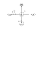
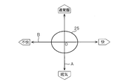
- FIG. 2 is a diagram for explaining a model for estimating the driver state in two axes.
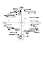
- FIG. 3 is a diagram for explaining Russell's emotional ring model.
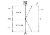
- FIG. 4 is a diagram for explaining a tactile element map for controlling a person.
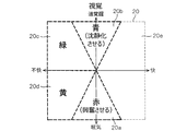
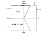
- FIG. 5 is a diagram for explaining a visual element map for controlling a person.
- FIG. 6 is a diagram for explaining an olfactory element map for controlling a person,
- FIG. 7 is a diagram for explaining a taste element map for controlling a person.
- FIG. 1 is a functional block diagram of a driving assistance apparatus showing the first embodiment.
- FIG. 2 is a diagram for explaining a model for estimating the driver state in two axes.
- FIG. 3 is a diagram for explaining Russell's emotional ring model.
- FIG. 4 is a diagram for explaining a tactile element map for controlling a person.
- FIG. 5 is a diagram
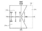
- FIG. 8 is a diagram (part 1) for explaining an auditory element map for controlling a person.
- FIG. 9 is a diagram (part 2) for explaining an auditory element map for controlling a person.
- FIG. 10 is a flowchart of the control for estimating the driver state and executing the HMI control.
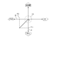
- FIG. 11 is a diagram for explaining the distance from the origin of the driving suitability state to the position (P1, P2) where the driver state is estimated,
- FIG. 12 shows a second embodiment, and is a control flowchart for estimating the driver state and executing the HMI control.
- FIG. 13 shows the third embodiment and is a diagram (part 1) for explaining the region of the driving suitability state.
- FIG. 14 is a diagram (part 2) illustrating the region of the driving suitability state.
- the driving support device 1 is mounted on a vehicle (for example, an automobile), and includes a control unit 2 mainly composed of a microcomputer as shown in FIG.
- the control unit 2 includes a driver state estimation unit 3 that estimates a driver state, and an HMI (Human Machine) that performs various types of support (that is, actuation) for the driver in order to make the driver state suitable for driving. Interface) control unit 4.
- HMI Human Machine
- the controller 2 is connected with a camera image information acquisition unit 5, a vehicle information acquisition unit 6, and a biological information acquisition unit 7, and receives signals from them.
- various in-vehicle devices 8 mounted on the vehicle are connected to the control unit 2, and signals from these in-vehicle devices 8 are input.
- a manual operation input device 9 is connected to the control unit 2 and a manual operation signal from the manual operation input device 9 is input.
- the control unit 2 is connected to a communication device 10 that performs wireless communication with the outside, and the control unit 2 can communicate with the external server 11 via the communication device 10.
- the camera image information acquisition unit 5 includes a driver's seat camera that captures the driver's face and the like, and performs image recognition processing on the driver's face image captured by the driver's seat camera, thereby driving the driver's face direction, line of sight, and blinking. Etc., and is configured to transmit information of these detection results to the control unit 2.
- the vehicle information acquisition unit 6 includes a steering sensor, an accelerator sensor, a brake sensor, a clutch sensor, a vehicle speed sensor, a host vehicle position detection device, an inter-vehicle distance detection device, an in-vehicle camera that captures the front of the vehicle, a laser radar, and the like. Information of detection results by these in-vehicle sensors and in-vehicle detection devices is transmitted to the control unit 2.
- the biological information acquisition unit 7 includes various biological sensors such as a body temperature sensor, a heart rate sensor, a sweat sensor, and an electroencephalogram sensor, and information on detection results by these biological sensors (that is, various biological information of the driver, for example, body temperature information). , Heart rate information, sweat information, brain wave information, etc.) are transmitted to the control unit 2.
- various biological sensors such as a body temperature sensor, a heart rate sensor, a sweat sensor, and an electroencephalogram sensor, and information on detection results by these biological sensors (that is, various biological information of the driver, for example, body temperature information).
- Heart rate information, sweat information, brain wave information, etc. are transmitted to the control unit 2.
- the various in-vehicle devices 8 include a car navigation system, a car audio, an air conditioner, a power window, a light, a wiper, and the like, and are configured such that signals from these in-vehicle devices 8 are transmitted to the control unit 2.
- the manual operation input device 9 includes a touch panel provided on the display screen, various switches provided around the display, a remote control, and the like. When the driver operates the manual operation input device 9, the manual operation input device 9 is provided. The manual operation signal is transmitted to the control unit 2.
- control unit 2 is connected to a five-sensory action unit 12 that works on the five senses of the driver to make the driver's state suitable for driving.
- the five-sensory action unit 12 includes a tactile action part 13, a visual action part 14, an olfactory action part 15, a taste action part 16, and an auditory action part 17.
- the tactile action unit 13 includes a car air conditioner, a vibration device that adds vibration to the driver's seat, and the like, by blowing cool air or hot air on the driver's body, or by adding vibration to the driver's seat. Acts on the driver's tactile sensation.
- the visual action unit 14 includes a head-up display (HUD), a center information display (CID) arranged at the center of the instrument panel, various indicators, various displays (displays), etc. Information to be provided, warnings, and the like are displayed on the display device or the like as appropriate to affect the driver's vision.
- HUD head-up display
- CID center information display
- the olfactory action unit 15 includes a device that diffuses aroma (aroma), stimulating odor, and the like in the vehicle interior, and acts on the driver's olfaction by diffusing the aroma, stimulating odor, and the like into the vehicle.
- the taste action unit 16 includes a HUD, a CID, various displays, a sound output device, and the like, and acts on the driver's taste by performing display and sound output for recommending gum, beverages, food, and the like to the driver.
- the auditory action unit 17 includes an in-vehicle audio device, an audio output device, a buzzer, a speaker, and the like, and acts on the hearing of the driver by appropriately outputting music, audio information, warning sound, and the like to be provided to the driver from the speaker. To do.
- the control unit 2 mainly estimates the driver state based on the information from the various information acquisition units 5, 6, 7, etc. described above mainly by the software configuration, and the estimated driver state is the driving suitability state. If not, a process for driving the driver's state to the driving suitability state is executed by executing driving support for driving and controlling the five-sensory action unit 12. In this case, the driver state estimation process is executed by the driver state estimation unit 3, and the action process for changing the driver state to the driving suitability state is executed by the HMI control unit 4.
- the driver state estimation unit 3 uses, as state evaluation axes for estimating the driver's state, a state evaluation axis A for driver drowsiness-hyperwakening and a state evaluation axis B for driver comfort-discomfort.
- state evaluation axis A with the calm state as the origin (that is, the intersection of the two axes A and B), the evaluation is performed in, for example, five levels in the direction in which drowsiness becomes deeper, and 5 It is configured to evaluate in stages.
- the state evaluation axis B is configured so that, for example, five levels are evaluated in a direction in which comfort is deepened, and five levels are evaluated in a direction in which discomfort is deep, with the calm state being the origin.
- the driver state estimation unit 3 receives various information from the camera image information acquisition unit 5, the vehicle information acquisition unit 6, and the biological information acquisition unit 7, and based on the received various information, And the position P2 on the state evaluation axis B is estimated.
- the position P1 relatively accurately by appropriately using a well-known technique (for example, a technique such as a patent gazette) for the state evaluation axis A, that is, for estimating sleepiness-hyperwakening. It is.
- the position P1 as an estimation result is displayed on a display or the like, and the driver confirms the position P1, and the driver inputs a manual operation (that is, operates the manual operation input device 9). Is preferably configured to be changeable.
- the position P2 can be estimated relatively accurately by appropriately using a well-known technique (for example, a technique such as a patent publication) with respect to the state evaluation axis B, that is, estimation of comfort and discomfort. is there.
- a well-known technique for example, a technique such as a patent publication
- a threshold data group for determining pleasantness and discomfort in 10 stages is created.
- the position P2 as an estimation result is displayed on a display or the like so that the driver can confirm the position P2, and the driver can change the position P2 by manual operation input (that is, the manual operation input device 9). It is preferable to configure as described above.
- FIG. 3 is called Russell's emotional ring model.
- the HMI control unit 4 controls the five-sensing action unit 12 to drive the five senses of the driver, and the driver state, that is, the estimated positions (P1, P2) are shown in FIG. 3) Control to enter the region 18 in the above.
- the HMI control unit 4 generates an element map corresponding to FIG. 2 showing the driver state by two state evaluation axes A and B in advance for each of the five senses of the driver, that is, tactile sense, visual sense, smell sense, taste sense, and auditory sense. Created and stored in the memory in the control unit 2.
- the HMI control unit 4 then, based on each element map and the estimated position (P1, P2), the haptic action unit 13, the visual action part 14, the olfactory action part 15, the taste action part 16, and the auditory action part 17 Are controlled to be driven.
- the tactile element map 19 will be described with reference to FIG.
- the tactile action unit 13 in the sleepy and uncomfortable area 19a, the tactile action unit 13 is driven and, for example, a process of blowing cool air around the neck of the driver is executed.
- a process for driving the tactile action unit 13 to generate, for example, a breeze in the passenger compartment is executed.
- the area 19c other than the areas 19a and 19b, no process for acting on the sense of touch is executed.
- the visual action unit 14 is driven to display, for example, red on a HUD or a display.
- red is considered to have an action that excites humans.
- the visual action unit 14 is driven to execute a process of displaying, for example, blue on a HUD or a display device.
- blue has the effect
- the visual action unit 14 is driven to execute processing for displaying, for example, green on a HUD or a display device.
- green has the effect
- the visual action unit 14 is driven to execute processing for displaying, for example, yellow on a HUD or a display device.
- yellow has the effect
- no processing that works on the vision is executed in the area 20e other than the areas 20a, 20b, 20c, and 20d.
- the olfactory element map 21 will be described with reference to FIG.
- the olfactory action unit 15 is driven to execute, for example, a process of diffusing a stimulating odor (eg, wasabi odor) into the vehicle interior.
- a stimulating odor eg, wasabi odor
- a process of driving the olfactory action unit 15 to diffuse, for example, aroma into the passenger compartment is executed.
- the taste element map 22 will be described with reference to FIG.
- a message recommending that the taste action unit 16 is driven to eat for example, gum (for example, mint gum) is displayed on the display. Executes processing that outputs audio. If chewing gum such as mint gum is chewed, it works to awaken humans.
- a process for driving the taste action unit 16 to display a message recommending eating sweet chocolate on the display or outputting the voice is executed. Eating sweets works to calm humans.
- the region 22c other than the regions 22a and 22b, no process for acting on the sense of smell is executed.
- the auditory element map 23 will be described with reference to FIG.
- the auditory action unit 17 in the sleepy area 23a, the auditory action unit 17 is driven to play, for example, a marching song or rock music, or to play an interesting story. Execute. Also, in the region 23b with over-awakening, the auditory action unit 17 is driven to reproduce, for example, healing music, or to output or display a message recommending deep breathing. Further, in the region 23c where there is over-awakening and unpleasantness or sleepiness and unpleasantness, the auditory action unit 17 is driven and, for example, processing for reproducing Mozart music (ie, classical music) or the like is executed.
- element maps 19, 20, 21, 22, and 23 are examples, and one or more element maps can be created and used for tactile sensation, visual sense, smell sense, taste sense, and auditory sense, respectively. It is preferable to configure.
- an element map 24 shown in FIG. 9 is another element map of hearing.
- the auditory action unit 17 is driven to play, for example, music in a minor tone as a tune, having a low frequency and a fast tempo. Execute the process of increasing the volume and playing.
- the auditory action unit 17 is driven to play, for example, music in a major tone as a melody and having a high frequency and a slow tempo at a low volume. Execute.
- the area 24c other than the areas 24a and 24b, no process for acting on hearing is performed.
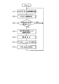
- step S ⁇ b> 10 of FIG. 10 the control unit 2 acquires camera image information, vehicle information, and biological information from the camera image information acquisition unit 5, the vehicle information acquisition unit 6, and the biological information acquisition unit 7.
- the driver state estimation unit 3 estimates the positions P1 and P2 on the two state evaluation axes A and B shown in FIGS. 2 and 3, and estimates the driver state (ie, emotion). In this case, it is preferable that the estimated positions P1 and P2 on the two state evaluation axes A and B are corrected (ie, self-reported) by manual operation of the driver as necessary. Then, the driver state estimation result, that is, the information on the positions (P1, P2) in FIGS. 2 and 3 is transmitted from the driver state estimation unit 3 to the HMI control unit 4 of the control unit 2.
- step S30 the HMI control unit 4 determines whether or not the position (P1, P2) where the driver state is estimated is within the driving suitability state region 18 in FIGS. .
- the process proceeds to "YES” and returns to step S10.
- step S30 when the estimated position (P1, P2) is not within the driving suitability region 18 (NO), the process proceeds to step S40.
- step S40 as shown in FIG. 11, the HMI control unit 4 moves from the origin of the driving suitability state (that is, the intersection of the two state evaluation axes A and B) O to the estimated position (P1, P2).
- the distance a is calculated and acquired.
- the process proceeds to step S50, and the HMI control unit 4 determines an element that acts on the driver.
- the HMI control unit 4 determines an element that acts on the driver.
- one of the five senses of the driver that is, the sense of touch, vision, smell, taste, and hearing may be selected at random, and control may be performed so as to act on the selected element.
- the selection order may be determined in advance. In this configuration, an element different from the previously controlled (ie, selected) element among the plurality of elements is selected.
- any two, three, or four of the five senses may be selected at random, and the selected two, three, or four elements may be controlled to operate. You may control to work on.
- a combination, order, or the like to be selected may be determined in advance. Also in this configuration, an element different from the previously controlled (ie, selected) element among the plurality of elements is selected.
- the element maps 19 to 24 corresponding to the determined elements are read from the memory.
- the estimated position (P1, P2) of the driver state shown in FIG. 11 falls within the driving suitability state region 18 for the selected element, that is, the position HMI control is performed so that the distance a between (P1, P2) and the origin O is eliminated.
- the selection order may be determined in advance.
- the selected positions (P1, P2) shown in FIG. 11 are selected so as to fall within the driving suitability region 18 for each of the selected elements.
- HMI control is preferably performed so that the distance a between the position (P1, P2) and the origin O is eliminated.
- the HMI control of a plurality of elements is executed substantially simultaneously, that is, with substantially parallel processing.
- the strength of the HMI control is configured to be substantially the same for the selected plurality of elements. That is, when the strength of HMI control for HMI control is set to “1” so that the distance “a” shown in FIG. 11 disappears, the strength of each HMI control is set to “1” for a plurality of selected elements. It was configured as follows. On the other hand, you may comprise so that the intensity
- the strength of HMI control corresponding to the distance a shown in FIG. 11 is set to “1” as described above
- the element C1 For example, the strength of the HMI control is set to “0.3”, the strength of the HMI control of the element C2 is set to “0.5”, for example, and the strength of the HMI control of the element C3 is set to “0.2”, for example. And set. Note that such setting of the strength of HMI control is an example, and can be changed as appropriate.
- one element when one element is selected and there are a plurality of element maps in the one element, one is selected from the plurality of element maps.
- one is selected from the plurality of element maps.
- a plurality of element maps may be selected, and the strength of HMI control when performing HMI control using the selected plurality of element maps may be changed for each of the plurality of element maps.
- the HMI control unit 4 includes an element map corresponding to the selected (ie, determined) element, estimated positions (P1, P2) on the two state evaluation axes A and B,
- the actuation method that is, the HMI control method
- the element is the tactile sense shown in FIG. 4 and the estimated position (P1, P2) is within the region 19a of the element map 19, an action of blowing cold air to the neck of the driver Decide how.
- the amount of cold air, the blowing time, etc. are determined based on the estimated position (P1, P2) or the setting value of the strength of HMI control.
- the other elements are similarly configured to determine the actuation method.
- the position (P1, P2) where the driver state is estimated is in a region where the control is not executed (for example, the region 19c in FIG. 4)
- the setting is made so that the HMI control is not executed.
- step S70 where the HMI control unit 4 executes HMI control (that is, support), specifically, the tactile action unit 13, the visual action unit 14, By driving and controlling the olfactory action unit 15, the taste action part 16, or the auditory action part 17, the driver's five senses, that is, touch, vision, smell, taste, and hearing are acted on. This improves the state of the driver.
- step S60 when it is set not to execute the HMI control, the process of step S70 is skipped (that is, the process of step S70 is not executed).
- step S10 camera image information, vehicle information, and biological information are acquired, and the processes of steps S20 to S70 are repeatedly executed.
- the state of the driver is estimated again, and the five senses of the driver, that is, the sense of touch, vision, smell, taste, and hearing are executed as necessary, that is, feedback control of HMI control is executed.
- It has a configuration.
- the HMI control strength is reduced to prevent the occurrence of overshoot of the HMI control as much as possible. It is preferable to control so as to.
- the driver state estimating unit 3 that estimates the driver state with respect to two axes of the sleepiness-hyperawake state evaluation axis A and the pleasant-unpleasant state evaluation axis B;
- the five senses acting part 12 that works with a plurality of elements that control a person and the five senses acting part 12 based on the estimation results of the two states of the driver state.
- an HMI control unit 4 that controls an element different from the previously controlled element.
- the HMI control unit 4 is configured to control elements different from the previously controlled elements when driving the five-sensory action unit 12, so that the driver performs HMI control (that is, improves the driver state). To get used to it).
- control part 4 is comprised so that the intensity
- control part 4 since the control part 4 is comprised so that two or more elements in the some element of the five sense effect
- the control unit 4 when the driver state is away from the driving suitability state, the control unit 4 increases the number of elements to be controlled or increases the strength of HMI control of the elements. Is configured to reduce the number of elements to be controlled or to reduce the strength of HMI control of the elements when it approaches the driving suitability state, it is possible to prevent the occurrence of overshoot of HMI control as much as possible. it can.
- the five sense action parts 12 are the tactile action part 13 which acts on a tactile sense, the visual action part 14 which acts on vision, the olfactory action part 15 which acts on olfaction, and the taste action which acts on taste. It comprised so that it might have the part 16 and the auditory effect part 17 which acts on hearing. According to this configuration, since it is possible to work on the five senses of the driver, the possibility that the state of the driver is suitable for driving increases.
- the HMI control unit 4 includes the element maps 19 to 24 for driving and controlling the five-sensory action unit 12 corresponding to the driver state estimation results regarding the two state evaluation axes A and B. Because it is configured, you can work with the five senses of the driver. Furthermore, since the element maps 19 to 24 are provided for each sense of touch, vision, smell, taste, and hearing, which are the five senses of the driver, it is possible to work more finely with the five senses of the driver.
- the driver state is estimated with respect to the two axes. Based on the current estimation result regarding the shaft, feedback control for driving and controlling the five-sensory action unit 12 is performed. According to this configuration, it is possible to work on the five senses of the driver while performing feedback control, so that the possibility of making the driver's state suitable for driving can be further increased.
- FIG. 12 shows a second embodiment.
- symbol is attached
- the tactile action part 13, the visual action part 14, the olfactory action part 15, the taste action part 16 or the auditory action part 17 are changed.
- the driver's five senses that is, the sense of touch, vision, smell, taste, and hearing, are acted on, and then a set time is awaited for the effect of the act to appear.
- step S70 the process proceeds to step S80, and the control unit 2 starts driving the five-sensory action unit 12, and then whether or not a set time (for example, 3 minutes, 5 minutes or 10 minutes) has elapsed. Determine whether. If the set time has not elapsed, the process proceeds to “NO” and waits for the set time to elapse.
- step S80 when the set time has elapsed (YES), the process returns to step S10 and the above-described processing is repeatedly executed.
- step S60 when the setting for not performing the HMI control is made, the process of step S70 may be skipped, and then the process of waiting for the set time of step S80 to be executed may be executed. Or you may comprise so that the process which waits for progress of the setting time of step S80 may also be skipped.
- the configuration of the second embodiment other than that described above is the same as the configuration of the first embodiment. Therefore, in the second embodiment, substantially the same operational effects as in the first embodiment can be obtained.
- the driver's five senses are waited for and the effect of the working is sufficiently exhibited. Can do. Thereby, it is possible to prevent the control of the five-sensory action unit 12 and the like from being performed excessively during the feedback control of the HMI control.
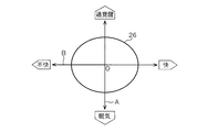
- (Third embodiment) 13 and 14 show a third embodiment.
- symbol is attached
- the driving suitability state is indicated by a region 18 in FIG. 2, and the size of the driving suitability state region 18 is fixedly determined in advance.
- the size of the driving suitability state area is changed according to the driving skill level of the driver, self-reporting, and the like.
- the size of the region 25 in the driving suitability state is relatively small, for example, the same size or smaller than the region 18.
- the size of the driving suitability state area 26 is set larger than the driving suitability state area 25 of the beginner driver, as shown in FIG.
- the HMI control is executed.
- the determination of whether the driver is a driving beginner or an expert is preferably made automatically based on camera image information, vehicle information, biometric information, and the like. Moreover, you may comprise so that a driver
- control unit 4 can change the size of the driving suitability state regions 25 and 26 on the plane indicating the state of the driver constituted by the two state evaluation axes A and B. Since it is configured, it is possible to adjust whether or not to execute the HMI control in accordance with the driving skill level of the driver.
- the said 3rd Embodiment although comprised so that two types of magnitude
Landscapes
- Physics & Mathematics (AREA)
- General Physics & Mathematics (AREA)
- Traffic Control Systems (AREA)
Applications Claiming Priority (2)
| Application Number | Priority Date | Filing Date | Title |
|---|---|---|---|
| JP2016-155651 | 2016-08-08 | ||
| JP2016155651A JP6668999B2 (ja) | 2016-08-08 | 2016-08-08 | 運転支援装置 |
Publications (1)
| Publication Number | Publication Date |
|---|---|
| WO2018030019A1 true WO2018030019A1 (ja) | 2018-02-15 |
Family
ID=61162123
Family Applications (1)
| Application Number | Title | Priority Date | Filing Date |
|---|---|---|---|
| PCT/JP2017/023741 Ceased WO2018030019A1 (ja) | 2016-08-08 | 2017-06-28 | 運転支援装置 |
Country Status (2)
| Country | Link |
|---|---|
| JP (1) | JP6668999B2 (enExample) |
| WO (1) | WO2018030019A1 (enExample) |
Families Citing this family (4)
| Publication number | Priority date | Publication date | Assignee | Title |
|---|---|---|---|---|
| KR102574937B1 (ko) * | 2018-05-18 | 2023-09-05 | 현대자동차주식회사 | 차량 및 그 제어 방법 |
| WO2020162362A1 (ja) | 2019-02-04 | 2020-08-13 | 日本電気株式会社 | 覚醒度制御装置、覚醒度制御方法および記録媒体 |
| WO2020162358A1 (ja) | 2019-02-04 | 2020-08-13 | 日本電気株式会社 | 覚醒度制御装置、覚醒度制御方法および記録媒体 |
| JP2021012409A (ja) * | 2019-07-03 | 2021-02-04 | 株式会社デンソー | 車載システム |
Citations (7)
| Publication number | Priority date | Publication date | Assignee | Title |
|---|---|---|---|---|
| JPH0991569A (ja) * | 1995-09-25 | 1997-04-04 | Mitsubishi Electric Corp | 覚醒低下警報装置 |
| JP2007133692A (ja) * | 2005-11-10 | 2007-05-31 | Toyota Motor Corp | 運転行動評価装置 |
| JP2009208727A (ja) * | 2008-03-06 | 2009-09-17 | Denso Corp | 自動車用ユーザーもてなしシステム |
| JP2011039601A (ja) * | 2009-08-06 | 2011-02-24 | Nissan Motor Co Ltd | 覚醒度調整装置及び方法 |
| WO2011125166A1 (ja) * | 2010-04-05 | 2011-10-13 | トヨタ自動車株式会社 | 生体状態判定装置 |
| WO2013175594A1 (ja) * | 2012-05-23 | 2013-11-28 | トヨタ自動車株式会社 | ドライバ状態判定装置及びドライバ状態判定方法 |
| JP2015110411A (ja) * | 2011-02-18 | 2015-06-18 | 本田技研工業株式会社 | 運転者の挙動に応答するシステムおよび方法 |
Family Cites Families (2)
| Publication number | Priority date | Publication date | Assignee | Title |
|---|---|---|---|---|
| JP2007271378A (ja) * | 2006-03-30 | 2007-10-18 | Denso Corp | 車載ナビゲーション装置 |
| JP6661264B2 (ja) * | 2014-09-24 | 2020-03-11 | 矢崎エナジーシステム株式会社 | 警報装置 |
-
2016
- 2016-08-08 JP JP2016155651A patent/JP6668999B2/ja not_active Expired - Fee Related
-
2017
- 2017-06-28 WO PCT/JP2017/023741 patent/WO2018030019A1/ja not_active Ceased
Patent Citations (7)
| Publication number | Priority date | Publication date | Assignee | Title |
|---|---|---|---|---|
| JPH0991569A (ja) * | 1995-09-25 | 1997-04-04 | Mitsubishi Electric Corp | 覚醒低下警報装置 |
| JP2007133692A (ja) * | 2005-11-10 | 2007-05-31 | Toyota Motor Corp | 運転行動評価装置 |
| JP2009208727A (ja) * | 2008-03-06 | 2009-09-17 | Denso Corp | 自動車用ユーザーもてなしシステム |
| JP2011039601A (ja) * | 2009-08-06 | 2011-02-24 | Nissan Motor Co Ltd | 覚醒度調整装置及び方法 |
| WO2011125166A1 (ja) * | 2010-04-05 | 2011-10-13 | トヨタ自動車株式会社 | 生体状態判定装置 |
| JP2015110411A (ja) * | 2011-02-18 | 2015-06-18 | 本田技研工業株式会社 | 運転者の挙動に応答するシステムおよび方法 |
| WO2013175594A1 (ja) * | 2012-05-23 | 2013-11-28 | トヨタ自動車株式会社 | ドライバ状態判定装置及びドライバ状態判定方法 |
Also Published As
| Publication number | Publication date |
|---|---|
| JP2018025870A (ja) | 2018-02-15 |
| JP6668999B2 (ja) | 2020-03-18 |
Similar Documents
| Publication | Publication Date | Title |
|---|---|---|
| JP5842857B2 (ja) | 覚醒度改善装置 | |
| CN108430818B (zh) | 用于操作机动车辆的方法,驾驶员辅助系统和机动车辆 | |
| US9266018B2 (en) | Customizable in-vehicle gaming system | |
| JP5228970B2 (ja) | 居眠り防止装置 | |
| CN107458325A (zh) | 用于在自主驾驶运载工具处提供积极信息娱乐的系统 | |
| JP6776681B2 (ja) | ドライバ状態判定装置、及びドライバ状態判定プログラム | |
| WO2018030019A1 (ja) | 運転支援装置 | |
| JP2018169706A (ja) | 車両運転支援システム | |
| WO2018030018A1 (ja) | 運転支援装置 | |
| JP2018167775A (ja) | 車両運転支援システム及び車両運転支援方法 | |
| US20200073478A1 (en) | Vehicle and control method thereof | |
| CN111783550B (zh) | 驾驶人情绪的监控调节方法及系统 | |
| EP3755596B1 (en) | Cognitive state-based stimuli | |
| JP2018189720A (ja) | 情報出力制御装置、情報出力制御方法、情報出力システム、およびプログラム | |
| JP2011118831A (ja) | 覚醒支援装置 | |
| JP6579043B2 (ja) | 車両用運転支援システム | |
| JP7540319B2 (ja) | 覚醒装置 | |
| JP2004110546A (ja) | 表示装置、音響装置、およびアクチュエータ制御装置 | |
| JP2020020987A (ja) | 車内システム | |
| WO2017187986A1 (ja) | 車載機器制御装置 | |
| JP2021171539A (ja) | 乗員感情伝達装置 | |
| JP2019008427A (ja) | 覚醒維持装置 | |
| JP6428748B2 (ja) | 運転支援システム | |
| EP4354457A1 (en) | System and method to detect automotive stress and/or anxiety in vehicle operators and implement remediation measures via the cabin environment | |
| JP7712861B2 (ja) | 情報提供支援方法、情報提供支援装置、情報提供支援プログラム、及び、情報提供システム |
Legal Events
| Date | Code | Title | Description |
|---|---|---|---|
| 121 | Ep: the epo has been informed by wipo that ep was designated in this application |
Ref document number: 17839093 Country of ref document: EP Kind code of ref document: A1 |
|
| NENP | Non-entry into the national phase |
Ref country code: DE |
|
| 122 | Ep: pct application non-entry in european phase |
Ref document number: 17839093 Country of ref document: EP Kind code of ref document: A1 |