WO2018025569A1 - Compresseur à spirale - Google Patents
Compresseur à spirale Download PDFInfo
- Publication number
- WO2018025569A1 WO2018025569A1 PCT/JP2017/024817 JP2017024817W WO2018025569A1 WO 2018025569 A1 WO2018025569 A1 WO 2018025569A1 JP 2017024817 W JP2017024817 W JP 2017024817W WO 2018025569 A1 WO2018025569 A1 WO 2018025569A1
- Authority
- WO
- WIPO (PCT)
- Prior art keywords
- pressure
- back pressure
- chamber
- valve
- scroll
- Prior art date
Links
Images


Classifications
-
- F—MECHANICAL ENGINEERING; LIGHTING; HEATING; WEAPONS; BLASTING
- F04—POSITIVE - DISPLACEMENT MACHINES FOR LIQUIDS; PUMPS FOR LIQUIDS OR ELASTIC FLUIDS
- F04C—ROTARY-PISTON, OR OSCILLATING-PISTON, POSITIVE-DISPLACEMENT MACHINES FOR LIQUIDS; ROTARY-PISTON, OR OSCILLATING-PISTON, POSITIVE-DISPLACEMENT PUMPS
- F04C18/00—Rotary-piston pumps specially adapted for elastic fluids
- F04C18/02—Rotary-piston pumps specially adapted for elastic fluids of arcuate-engagement type, i.e. with circular translatory movement of co-operating members, each member having the same number of teeth or tooth-equivalents
- F04C18/0207—Rotary-piston pumps specially adapted for elastic fluids of arcuate-engagement type, i.e. with circular translatory movement of co-operating members, each member having the same number of teeth or tooth-equivalents both members having co-operating elements in spiral form
- F04C18/0215—Rotary-piston pumps specially adapted for elastic fluids of arcuate-engagement type, i.e. with circular translatory movement of co-operating members, each member having the same number of teeth or tooth-equivalents both members having co-operating elements in spiral form where only one member is moving
-
- F—MECHANICAL ENGINEERING; LIGHTING; HEATING; WEAPONS; BLASTING
- F04—POSITIVE - DISPLACEMENT MACHINES FOR LIQUIDS; PUMPS FOR LIQUIDS OR ELASTIC FLUIDS
- F04C—ROTARY-PISTON, OR OSCILLATING-PISTON, POSITIVE-DISPLACEMENT MACHINES FOR LIQUIDS; ROTARY-PISTON, OR OSCILLATING-PISTON, POSITIVE-DISPLACEMENT PUMPS
- F04C18/00—Rotary-piston pumps specially adapted for elastic fluids
- F04C18/02—Rotary-piston pumps specially adapted for elastic fluids of arcuate-engagement type, i.e. with circular translatory movement of co-operating members, each member having the same number of teeth or tooth-equivalents
-
- F—MECHANICAL ENGINEERING; LIGHTING; HEATING; WEAPONS; BLASTING
- F04—POSITIVE - DISPLACEMENT MACHINES FOR LIQUIDS; PUMPS FOR LIQUIDS OR ELASTIC FLUIDS
- F04C—ROTARY-PISTON, OR OSCILLATING-PISTON, POSITIVE-DISPLACEMENT MACHINES FOR LIQUIDS; ROTARY-PISTON, OR OSCILLATING-PISTON, POSITIVE-DISPLACEMENT PUMPS
- F04C23/00—Combinations of two or more pumps, each being of rotary-piston or oscillating-piston type, specially adapted for elastic fluids; Pumping installations specially adapted for elastic fluids; Multi-stage pumps specially adapted for elastic fluids
- F04C23/008—Hermetic pumps
-
- F—MECHANICAL ENGINEERING; LIGHTING; HEATING; WEAPONS; BLASTING
- F04—POSITIVE - DISPLACEMENT MACHINES FOR LIQUIDS; PUMPS FOR LIQUIDS OR ELASTIC FLUIDS
- F04C—ROTARY-PISTON, OR OSCILLATING-PISTON, POSITIVE-DISPLACEMENT MACHINES FOR LIQUIDS; ROTARY-PISTON, OR OSCILLATING-PISTON, POSITIVE-DISPLACEMENT PUMPS
- F04C27/00—Sealing arrangements in rotary-piston pumps specially adapted for elastic fluids
- F04C27/005—Axial sealings for working fluid
-
- F—MECHANICAL ENGINEERING; LIGHTING; HEATING; WEAPONS; BLASTING
- F04—POSITIVE - DISPLACEMENT MACHINES FOR LIQUIDS; PUMPS FOR LIQUIDS OR ELASTIC FLUIDS
- F04C—ROTARY-PISTON, OR OSCILLATING-PISTON, POSITIVE-DISPLACEMENT MACHINES FOR LIQUIDS; ROTARY-PISTON, OR OSCILLATING-PISTON, POSITIVE-DISPLACEMENT PUMPS
- F04C29/00—Component parts, details or accessories of pumps or pumping installations, not provided for in groups F04C18/00 - F04C28/00
- F04C29/04—Heating; Cooling; Heat insulation
-
- F—MECHANICAL ENGINEERING; LIGHTING; HEATING; WEAPONS; BLASTING
- F04—POSITIVE - DISPLACEMENT MACHINES FOR LIQUIDS; PUMPS FOR LIQUIDS OR ELASTIC FLUIDS
- F04C—ROTARY-PISTON, OR OSCILLATING-PISTON, POSITIVE-DISPLACEMENT MACHINES FOR LIQUIDS; ROTARY-PISTON, OR OSCILLATING-PISTON, POSITIVE-DISPLACEMENT PUMPS
- F04C29/00—Component parts, details or accessories of pumps or pumping installations, not provided for in groups F04C18/00 - F04C28/00
- F04C29/12—Arrangements for admission or discharge of the working fluid, e.g. constructional features of the inlet or outlet
- F04C29/124—Arrangements for admission or discharge of the working fluid, e.g. constructional features of the inlet or outlet with inlet and outlet valves specially adapted for rotary or oscillating piston pumps
-
- F—MECHANICAL ENGINEERING; LIGHTING; HEATING; WEAPONS; BLASTING
- F04—POSITIVE - DISPLACEMENT MACHINES FOR LIQUIDS; PUMPS FOR LIQUIDS OR ELASTIC FLUIDS
- F04C—ROTARY-PISTON, OR OSCILLATING-PISTON, POSITIVE-DISPLACEMENT MACHINES FOR LIQUIDS; ROTARY-PISTON, OR OSCILLATING-PISTON, POSITIVE-DISPLACEMENT PUMPS
- F04C2240/00—Components
- F04C2240/80—Other components
-
- F—MECHANICAL ENGINEERING; LIGHTING; HEATING; WEAPONS; BLASTING
- F04—POSITIVE - DISPLACEMENT MACHINES FOR LIQUIDS; PUMPS FOR LIQUIDS OR ELASTIC FLUIDS
- F04C—ROTARY-PISTON, OR OSCILLATING-PISTON, POSITIVE-DISPLACEMENT MACHINES FOR LIQUIDS; ROTARY-PISTON, OR OSCILLATING-PISTON, POSITIVE-DISPLACEMENT PUMPS
- F04C2270/00—Control; Monitoring or safety arrangements
- F04C2270/18—Pressure
- F04C2270/185—Controlled or regulated
Definitions
- the present invention relates to a scroll compressor that compresses refrigerant in a refrigeration cycle.
- the scroll compressor includes a scroll unit having a fixed scroll and a turning scroll that are meshed with each other.
- the scroll unit revolves around the axis of the fixed scroll to increase or decrease the volume of the compression chamber defined by the fixed scroll and the orbiting scroll, and compresses and discharges the gas refrigerant.
- the back pressure is applied to the back surface of the orbiting scroll and pressed against the fixed scroll, so that the orbiting scroll is prevented from being separated from the fixed scroll during the compression operation, thereby making it difficult to cause a compression failure.
- the back pressure applied to the back surface of the orbiting scroll is adjusted based on the suction pressure and the discharge pressure of the gaseous refrigerant as described in International Publication No. 2012/147145 pamphlet (Patent Document 1).
- the gas injection cycle is a refrigerant circuit in which a compressor, a condenser, a first expansion valve, a gas-liquid separator, a second expansion valve, and an evaporator are arranged in this order, and gas refrigerant separated by the gas-liquid separator is removed.
- the refrigeration effect is improved by injection into the compressor chamber.
- the target back pressure changes according to the pressure of the gaseous refrigerant injected into the compression chamber (injection pressure). Specifically, when the injection pressure is high, the back pressure is insufficient and the force for pressing the orbiting scroll against the fixed scroll is weakened. For example, the gas refrigerant may leak from the compression chamber and the compression efficiency may be reduced. There is. On the other hand, when the injection pressure is low, the back pressure becomes excessive, and for example, the power for revolving the orbiting scroll is increased, which may cause a reduction in compression efficiency and galling of the scroll wrap.
- an object of the present invention is to optimize the back pressure in a scroll compressor to which an injection cycle is applied.
- the scroll compressor increases or decreases the volume of the compression chamber partitioned by the fixed scroll and the orbiting scroll, and injects the gaseous refrigerant taken out from the middle of the refrigerant circuit into the compression chamber, sucks, compresses and compresses the gaseous refrigerant.
- the pressure of the scroll unit for discharging and the pressure of the back pressure chamber that presses the orbiting scroll toward the fixed scroll, the suction pressure of the gas refrigerant sucked into the compression chamber, the discharge pressure of the gas refrigerant discharged from the compression chamber, and the compression chamber And a back pressure adjusting valve that adjusts according to the injection pressure of the gaseous refrigerant injected into the.
- FIG. 1 shows an example of a refrigeration cycle 100 to which a gas injection cycle is applied, which is a premise of the present embodiment.
- the refrigeration cycle 100 is mentioned as an example of a refrigeration circuit.
- the compressor 120, the condenser 130, the first expansion valve 140, the gas-liquid separator 150, the second expansion valve 160, and the evaporator 170 are arranged in this order with respect to the refrigerant pipe 110 through which the refrigerant circulates. It is configured.
- the compressor 120 compresses the low-temperature / low-pressure gas refrigerant into a high-temperature / high-pressure gas refrigerant.
- the condenser 130 cools the high-temperature / high-pressure gaseous refrigerant that has passed through the compressor 120 to form a high-pressure / low-temperature liquid refrigerant.
- the first expansion valve 140 and the second expansion valve 160 depressurize the low-temperature / high-pressure liquid refrigerant in two stages to form a low-temperature / low-pressure liquid refrigerant.
- the evaporator 170 vaporizes the low-temperature / low-pressure liquid refrigerant into a low-temperature / low-pressure gas refrigerant.
- the gas-liquid separator 150 separates the gaseous refrigerant from the intermediate-pressure liquid refrigerant decompressed by the first expansion valve 140, and supplies this to the compressor 120 as an injection gas.
- FIG. 2 shows a Mollier diagram of the gas injection cycle.
- the high-pressure Ph liquid refrigerant that has passed through the condenser 130 is reduced to an intermediate injection pressure Pinj by the first expansion valve 140 to become a gas-liquid two-phase, and is introduced into the gas-liquid separator 150.
- the state of the inlet is point A, and it is separated into saturated gas refrigerant at point B and saturated liquid refrigerant at point C inside. Thereafter, the saturated liquid refrigerant is further depressurized by the second expansion valve 160 to become a low pressure Pl and introduced into the evaporator 170.
- the evaporator 170 exchanges heat with the outside air, whereby the low-pressure Pl liquid refrigerant is vaporized to become a gaseous refrigerant and introduced into the compressor 120.
- the saturated gas refrigerant having the injection pressure Pinj is injected into the compression chamber of the compressor 120.
- a scroll compressor 200 that compresses a gaseous refrigerant using a fixed scroll and a turning scroll will be described.
- FIG. 3 shows an example of the scroll compressor 200.
- the scroll compressor 200 includes a scroll unit 220, a housing 240 having a gas refrigerant suction chamber H ⁇ b> 1 and a discharge chamber H ⁇ b> 2, an electric motor 260 as a drive unit that drives the scroll unit 220, and drive control for the electric motor 260. And an inverter 280. Note that the inverter 280 may not be incorporated in the scroll compressor 200.
- the scroll unit 220 includes a fixed scroll 222 and a turning scroll 224 that are meshed with each other.
- the fixed scroll 222 includes a disc-shaped bottom plate 222A and an involute-shaped (spiral shape) wrap 222B standing from one surface of the bottom plate 222A.
- the orbiting scroll 224 includes a disc-shaped bottom plate 224A and an involute-shaped wrap 224B standing from one surface of the bottom plate 224A.
- the fixed scroll 222 and the orbiting scroll 224 are arranged so that the wraps 222B and 224B are engaged with each other. Specifically, the tip of the wrap 222B of the fixed scroll 222 is in contact with one surface of the bottom plate 224A of the orbiting scroll 224, and the tip of the wrap 224B of the orbiting scroll 224 is in contact with one surface of the bottom plate 222A of the fixed scroll 222. Is arranged. A tip seal (not shown) is attached to the tip of the wraps 222B and 224B.
- the fixed scroll 222 and the orbiting scroll 224 are arranged so that the side walls of the wraps 222B and 224B are partially in contact with each other with the circumferential angles of the wraps 222B and 224B being shifted from each other. Therefore, a crescent-shaped sealed space that functions as the compression chamber H3 is formed between the wrap 222B of the fixed scroll 222 and the wrap 224B of the orbiting scroll 224.
- the orbiting scroll 224 is disposed so as to be able to revolve around the axis of the fixed scroll 222 via a crank mechanism which will be described later in a state in which the rotation is prevented. Therefore, the scroll unit 220 moves the compression chamber H3 defined by the wrap 222B of the fixed scroll 222 and the wrap 224B of the orbiting scroll 224 to the center, and gradually reduces the volume thereof. As a result, the scroll unit 220 compresses the gaseous refrigerant sucked into the compression chamber H3 from the outer ends of the wraps 222B and 224B.
- the housing 240 includes a front housing 242 that houses the electric motor 260 and the inverter 280, a center housing 244 that houses the scroll unit 220, a rear housing 246, and an inverter cover 248.
- the front housing 242, the center housing 244, the rear housing 246, and the inverter cover 248 are integrally fastened by, for example, a fastener (not shown) including a bolt and a washer, so that the housing of the scroll compressor 200 is obtained.
- 240 is configured.
- the front housing 242 has a substantially cylindrical peripheral wall portion 242A and a partition wall portion 242B.
- the internal space of the front housing 242 is partitioned into a space for housing the electric motor 260 and a space for housing the inverter 280 by the partition wall portion 242B.
- the opening on one end side (the lower side in FIG. 3) of the peripheral wall portion 242 ⁇ / b> A is closed by the inverter cover 248. Further, the opening on the other end side (upper side in FIG. 3) of the peripheral wall portion 242A is closed by the center housing 244.
- the partition wall portion 242B has a substantially cylindrical support portion 242B1 that rotatably supports one end portion of a drive shaft 266, which will be described later, at the center portion in the radial direction, and protrudes toward the other end side of the peripheral wall portion 242A. Has been.
- a suction chamber H1 for gaseous refrigerant is defined by the peripheral wall portion 242A and the partition wall portion 242B of the front housing 242 and the center housing 244. Low-pressure and low-temperature gaseous refrigerant is sucked into the suction chamber H1 through a suction port P1 formed in the peripheral wall portion 242A.
- gas refrigerant flows around the electric motor 260 to cool the electric motor 260, and the upper space of the electric motor 260 and the lower space communicate with each other.
- a suction chamber H1 is formed.
- An appropriate amount of lubricating oil is stored in the suction chamber H1 in order to lubricate sliding parts such as the drive shaft 266 that is rotationally driven. For this reason, in the suction chamber H1, the gaseous refrigerant flows as a mixed fluid with the lubricating oil.
- the center housing 244 has a substantially bottomed cylindrical shape opened on the side opposite to the fastening side with the front housing 242, and can accommodate the scroll unit 220 therein.
- the center housing 244 has a cylindrical portion 244A and a bottom wall portion 244B on one end side thereof.
- the scroll unit 220 is accommodated in a space defined by the cylindrical portion 244A and the bottom wall portion 244B.
- a fitting portion 244A1 into which the fixed scroll 222 is fitted is formed on the other end side of the cylindrical portion 244A. Therefore, the opening of the center housing 244 is closed by the fixed scroll 222.
- the bottom wall portion 244 ⁇ / b> B is formed so that the central portion in the radial direction bulges toward the electric motor 260.
- a through hole for allowing the other end portion of the drive shaft 266 to pass therethrough is formed in the radial center portion of the bulging portion 244B1 of the bottom wall portion 244B.
- a fitting portion into which a bearing 300 that rotatably supports the other end portion of the drive shaft 266 is fitted is formed on the bulging portion 244B1 on the scroll unit 220 side.
- An annular thrust plate 310 is disposed between the bottom wall portion 244B of the center housing 244 and the bottom plate 224A of the orbiting scroll 224.
- the outer peripheral portion of the bottom wall portion 244 ⁇ / b> B receives a thrust force from the orbiting scroll 224 through the thrust plate 310.
- Seal members (not shown) are respectively embedded in the portions of the bottom wall portion 244B and the bottom plate 224A that are in contact with the thrust plate 310.
- a back pressure chamber H4 is formed between the end surface of the bottom plate 224A on the electric motor 260 side and the bottom wall portion 244B, that is, between the end surface of the orbiting scroll 224 opposite to the fixed scroll 222 and the center housing 244.
- a gas refrigerant (specifically, a mixed fluid of a gas refrigerant and lubricating oil) is introduced into the center housing 244 from the suction chamber H1 to the space H5 near the outer ends of the wraps 222B and 224B of the scroll unit 220.
- a refrigerant introduction passage L1 is formed. Since the refrigerant introduction passage L1 communicates the space H5 and the suction chamber H1, the pressure in the space H5 is equal to the pressure in the suction chamber H1 (suction pressure Ps).
- the rear housing 246 is fastened to a fitting portion 244A1 side end portion of the cylindrical portion 244A of the center housing 244 by a fastener. Accordingly, the bottom plate 222A of the fixed scroll 222 is fixed while being sandwiched between the fitting portion 244A1 and the rear housing 246. Further, the rear housing 246 has a substantially bottomed cylindrical shape that is open on the fastening side with the center housing 244, and includes a cylindrical portion 246A and a bottom wall portion 246B on the other end side.
- the gas refrigerant discharge chamber H2 is partitioned by the cylindrical portion 246A and the bottom wall portion 246B of the rear housing 246 and the bottom plate 222A of the fixed scroll 222.
- a compressed refrigerant discharge passage (discharge hole) L2 is formed in the central portion of the bottom plate 222A, and the discharge passage L2 restricts the flow from the discharge chamber H2 to the scroll unit 220, for example, a check valve made of a reed valve.
- a valve 320 is attached.
- Compressed refrigerant compressed in the compression chamber H3 of the scroll unit 220 is discharged into the discharge chamber H2 through the discharge passage L2 and the check valve 320.
- the compressed refrigerant in the discharge chamber H2 is discharged to the condenser 130 via the discharge port P2 formed in the bottom wall portion 246B.
- the rear housing 246 is provided with an oil separator for separating the lubricating oil from the compressed refrigerant in the discharge chamber H2.
- the compressed refrigerant from which the lubricating oil has been separated by the oil separator (a small amount of lubricating oil may remain) is discharged to the condenser 130 via the discharge port P2.
- the lubricating oil separated by the oil separator is guided to a pressure supply passage L3 described later.
- the flow of the gaseous refrigerant before or after mixing the lubricating oil is indicated by the hatched arrow, and the flow of the gaseous refrigerant (mixed fluid) mixed with the lubricating oil is indicated by the thick line arrow, which is separated from the gaseous refrigerant.
- the flow of the lubricated oil is indicated by white arrows.
- the pressure supply passage L3 is an example of a passage for supplying lubricating oil to the back pressure chamber.
- the electric motor 260 is made of, for example, a three-phase AC motor, and includes a rotor 262 and a stator core unit 264 disposed on the outer side in the radial direction of the rotor 262.
- a direct current from an on-vehicle battery (not shown) is converted into an alternating current by an inverter 280 and supplied to the electric motor 260.
- the rotor 262 is rotatably supported on the radially inner side of the stator core unit 264 via a drive shaft 266 that is press-fitted into a shaft hole formed at the center in the radial direction.
- One end of the drive shaft 266 is rotatably supported by the support portion 242B1 of the front housing 242.
- the other end portion of the drive shaft 266 passes through a through hole formed in the center housing 244 and is rotatably supported by the bearing 300.
- the crank mechanism includes a cylindrical boss portion 330 protruding from the end surface on the back pressure chamber H4 side of the bottom plate 224A of the orbiting scroll 224, and a crank 340 provided at the other end portion of the drive shaft 266. And an eccentric bush 350 attached in an eccentric state.
- the eccentric bush 350 is rotatably supported by the boss portion 330.
- a balancer weight 360 is attached to the other end portion of the drive shaft 266 (the end portion on the crank 340 side) to counter the centrifugal force during the operation of the orbiting scroll 224. Therefore, the orbiting scroll 224 can revolve around the axis of the fixed scroll 222 via the crank mechanism in a state in which the rotation is prevented.
- FIG. 5 is a block diagram for explaining the flow of the gaseous refrigerant in the scroll compressor 200.
- the low-pressure / low-temperature gas refrigerant from the evaporator 170 is introduced into the suction chamber H1 through the suction port P1, and then the outside of the scroll unit 220 through the refrigerant introduction passage L1. It is guided to a space H5 near the end. The gaseous refrigerant in the space H5 is taken into the compression chamber H3 of the scroll unit 220 and compressed.
- the compressed refrigerant compressed in the compression chamber H3 is discharged to the discharge chamber H2 via the discharge passage L2 and the check valve 320, and then discharged from the discharge chamber H2 to the condenser 130 via the discharge port P2.
- the scroll unit 220 is configured to compress the gaseous refrigerant flowing in through the suction chamber H1 in the compression chamber H3 and discharge the compressed refrigerant through the discharge chamber H2.
- the scroll compressor 200 further includes a back pressure adjusting valve 400 for adjusting the pressure of the back pressure chamber H4.
- the back pressure adjusting valve 400 operates in accordance with the suction pressure Ps of the suction chamber H1, the discharge pressure Pd of the discharge chamber H2, and the injection pressure Pinj.
- This is a mechanical (autonomous) flow control valve that automatically adjusts the valve opening so as to approach the target back pressure Pc corresponding to the pressure Pinj.
- the back pressure adjustment valve 400 is accommodated in an accommodation chamber 246 ⁇ / b> C formed in the bottom wall portion 246 ⁇ / b> B of the rear housing 246 so as to extend in a direction orthogonal to the central axis of the drive shaft 266 of the electric motor 260.
- the structure of the back pressure adjustment valve 400 and the back pressure adjustment operation will be described later.
- the scroll compressor 200 includes a pressure supply passage L3, a pressure release passage L4, a suction pressure sensing passage L5, an injection gas introduction passage L6, in addition to the refrigerant introduction passage L1 and the discharge passage L2.
- An injection pressure sensing passage L7 is provided.
- the pressure release passage L4 is given as an example of a passage for discharging the lubricating oil from the back pressure chamber.
- the pressure supply passage L3 is a passage for communicating the discharge chamber H2 and the back pressure chamber H4.
- the lubricating oil separated from the compressed refrigerant in the discharge chamber H2 by the oil separator is guided to the back pressure chamber H4 through the pressure supply passage L3 and is used for lubrication of each sliding portion. Further, the lubricating oil is supplied to the back pressure chamber H4 via the pressure supply passage L3, whereby the back pressure Pm of the back pressure chamber H4 increases.
- the pressure supply passage L3 includes a passage that connects the discharge chamber H2 and the storage chamber 246C, one end that opens into the storage chamber 246C, and the other end that communicates with the center housing 244 of the cylindrical portion 246A of the rear housing 246. It includes a passage that opens to the abutting end surface portion, and a passage that is connected to the passage and opens to the back pressure chamber H4 through the cylindrical portion 244A and the bottom wall portion 244B of the center housing 244.
- the back pressure adjusting valve 400 is arranged in the middle of the pressure supply passage L3 so as to constitute a part of the pressure supply passage L3. Therefore, the lubricating oil separated from the compressed refrigerant in the discharge chamber H2 is supplied to the back pressure chamber H4 via the pressure supply passage L3 while being appropriately decompressed by the back pressure adjusting valve 400. That is, by adjusting the opening of the pressure supply passage L3 connected to the inlet side (upstream side) of the back pressure chamber H4 with the back pressure adjustment valve 400, the flow rate of the lubricating oil flowing into the back pressure chamber H4 is increased or decreased. Then, the back pressure Pm is adjusted.
- the pressure relief passage L4 is a passage for communicating the back pressure chamber H4 and the suction chamber H1.
- An orifice OL1 is disposed in the middle of the pressure release passage L4.
- the pressure release passage L4 in which the orifice OL1 is disposed is formed so as to penetrate the drive shaft 266 and extend along the central axis of the drive shaft 266.
- the orifice OL1 is disposed, for example, at the end of the drive shaft 266 on the suction chamber H1 side (in FIG. 3, the support portion 242B1 side of the front housing 242).
- the lubricating oil in the back pressure chamber H4 is returned to the suction chamber H1 while the flow rate is limited by the orifice OL1.
- the suction pressure sensing passage L5 is a passage for sensing the suction pressure Ps of the suction chamber H1 in the back pressure regulating valve 400.
- the suction pressure sensing passage L5 has one end opened to the accommodation chamber 246C, the other end connected to the passage, and a passage opened to an end surface portion contacting the fixed scroll 222 of the cylindrical portion 246A of the rear housing 246. And a passage that passes through the outer periphery of the bottom plate 222A of the fixed scroll 222 and opens to the space H5.
- a suction pressure sensing branch passage L5A that branches from a predetermined portion of the suction pressure sensing passage L5 and opens to the bottom side of the storage chamber 246C is formed.
- the suction pressure sensing branch passage L5A is not shown for simplification of the drawing.
- the suction pressure sensing passage L5 is described as an example in which the suction pressure detection passage L5 opens into the space H5, but may be directly opened into the suction chamber H1.
- the injection gas introduction passage L6 is a passage for introducing and injecting the injection gas separated from the gaseous refrigerant by the gas-liquid separator 150 into the compression chamber H3.
- the injection gas introduction passage L6 has one end opened to the outer wall of the rear housing 246 and the other end connected to this passage and a passage opened to an end surface portion that contacts the fixed scroll 222 of the cylindrical portion 246A of the rear housing 246. And a passage that passes through the bottom plate 222A of the fixed scroll 222 and opens to the compression chamber H3.
- the injection is performed in the bottom wall portion 246B of the rear housing 246, which branches from a predetermined portion of the injection gas introduction passage L6 and opens into the storage chamber 246C.
- a pressure sensing passage L7 is formed.
- the orbiting scroll 224 is pressed toward the fixed scroll 222 by the back pressure Pm of the back pressure chamber H4.
- the resultant force of the back pressure Pm acting on the end surface on the back pressure chamber H4 side of the bottom plate 224A of the orbiting scroll 224 is smaller than the compression reaction force acting on the end surface on the compression chamber H3 side of the bottom plate 224A.
- the back pressure Pm is adjusted by the back pressure adjustment valve 400 so that the resultant force is greater than the compression reaction force.
- the back pressure adjustment valve 400 reduces the back pressure Pm so as to approach the target back pressure Pc so that the back pressure does not become excessive.
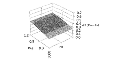
- FIG. 6 shows the theoretical value of the differential pressure ⁇ P required during the cooling operation
- FIG. 7 shows the theoretical value of the differential pressure ⁇ P required during the heating operation.
- the change characteristic of the differential pressure ⁇ P according to the injection pressure Pinj changes according to the rotational speed Nc.
- the differential pressure ⁇ P decreases as the rotational speed Nc increases.
- the differential pressure ⁇ P during the cooling operation is slightly lower than the differential pressure ⁇ P during the heating operation.
- the back pressure adjusting valve 400 increases or decreases the opening of the pressure supply passage L3 according to at least the suction pressure Ps, the discharge pressure Pd, the injection pressure Pinj, and the back pressure Pm, and the differential pressure ⁇ P shown in FIGS. Control to be
- FIG. 8 shows a first embodiment of a back pressure adjustment valve 400 that adjusts the flow rate of lubricating oil supplied to the back pressure chamber H4.
- the back pressure adjusting valve 400 includes a valve housing 410 having a substantially stepped cylindrical shape, a valve unit 420 inserted in the valve housing 410, a bellows assembly 430 that urges the valve unit 420 in the valve closing direction, have.
- the bellows assembly 430 is an example of an elastic body.
- the large-diameter portion of the valve housing 410 has a substantially cylindrical discharge pressure introduction chamber H6, a first pressure-sensitive chamber H7, a second pressure-sensitive chamber H8, and a substantially stepped shape along a direction away from the small-diameter portion.
- a third pressure sensing chamber H9 having a cylindrical shape is formed.
- the discharge pressure introduction chamber H6 is connected to the pressure supply passage L3 on the discharge chamber H2 side via a plurality of first communication holes 410A formed in the peripheral wall of the large diameter portion of the valve housing 410.
- the first pressure sensing chamber H7 is connected to the pressure supply passage L3 on the back pressure chamber H4 side via a plurality of second communication holes 410B formed in the peripheral wall of the large diameter portion of the valve housing 410.
- the second pressure sensing chamber H8 is connected to the injection pressure sensing passage L7 via a plurality of third communication holes 410C formed in the peripheral wall of the large diameter portion of the valve housing 410.
- the third pressure sensing chamber H9 is connected to the suction pressure sensing passage L5 via a fourth communication hole 410D formed in the peripheral wall of the large diameter portion of the valve housing 410.
- valve back pressure chamber H10 having a substantially cylindrical shape is formed in the small diameter portion of the valve housing 410.
- the valve back pressure chamber H10 is connected to a suction pressure sensing branch passage L5A branched from the suction pressure sensing passage L5 via a fifth communication hole 410E formed at the tip of the small diameter portion of the valve housing 410.
- the valve unit 420 includes a valve shaft 422 having a substantially cylindrical shape, a first valve body 424 having a substantially disk shape, and a second valve body 426 having a substantially cylindrical shape.
- the first valve body 424 and the second valve body 426 are integrated with the valve shaft 422 at a central portion in the axial direction with a predetermined interval.
- the outer diameter of the first valve body 424 is formed larger than the outer diameter of the second valve body 426.
- the 1st valve body 424 is mentioned as an example of a valve body.
- the first valve body 424 of the valve unit 420 is located in the first pressure sensing chamber H7, and the second valve body 426 is connected to the second pressure sensing chamber H8 and the third pressure sensing chamber.
- the valve unit 420 is disposed so as to be capable of reciprocating in the axial direction while penetrating the partition wall with the chamber H9. Further, a sixth communication hole 410F having an inner diameter larger than the outer diameter of the valve shaft 422 of the valve unit 420 is formed in the partition wall between the discharge pressure introduction chamber H6 and the first pressure sensing chamber H7 of the valve housing 410.
- valve unit 420 moves from the valve closing position to the valve opening direction, the distance between the partition wall and the first valve body 424 changes, and the first feeling is detected from the discharge pressure introduction chamber H6 via the sixth communication hole 410F.
- the flow rate of the lubricating oil for back pressure adjustment supplied while reducing the pressure to the pressure chamber H7 can be changed.
- a bellows assembly 430 that biases the first valve body 424 in the valve closing direction via the valve shaft 422 of the valve unit 420 is disposed.
- the bellows assembly 430 includes an axially expandable bellows 432, a coil spring 434 housed in the bellows 432, a first cap 436 that closes one end opening in the axial direction of the bellows 432, and a shaft of the bellows 432. And a second cap 438 that fits into the small diameter portion of the third pressure sensing chamber H9 while closing the other end opening in the direction.
- the one end part of the valve shaft 422 of the valve unit 420 is fitted in the recessed part 436A formed in the center part of the 1st cap 436 so that contact / separation is possible.
- a coil spring 440 that biases the first valve body 424 in the valve opening direction via the valve shaft 422 of the valve unit 420 is disposed.
- the back pressure adjusting valve 400 appropriately sets the pressure receiving area of each part of the valve unit 420, the pressure receiving area and spring constant of the bellows assembly 430, the spring constant of the coil spring 440, etc., as shown in FIG. 13 (during cooling operation). And it comes to have the operation characteristic shown in FIG. 14 (at the time of heating operation). Referring to these operating characteristics, it will be understood that the back pressure adjusting valve 400 adjusts the back pressure Pm of the back pressure chamber H4 in accordance with the injection pressure Pinj in addition to the suction pressure Ps and the discharge pressure Pd. For this reason, in the scroll compressor 200 to which the injection cycle is applied, the back pressure can be optimized.
- the back pressure adjusting valve 400 causes the first valve body 424, which is biased in the valve closing direction by the back pressure Pm of the bellows assembly 430 and the back pressure chamber H4, by the suction pressure Ps, the discharge pressure Pd, and the injection pressure Pinj. Move in the valve opening direction.
- the back pressure adjusting valve 400 adjusts the back pressure Pm of the back pressure chamber H4 by increasing or decreasing the flow rate of supplying the lubricating oil separated from the gas refrigerant compressed in the compression chamber H3 to the back pressure chamber H4. .
- FIG. 15 shows a second embodiment of the back pressure adjusting valve 400 that adjusts the flow rate of the lubricating oil supplied to the back pressure chamber H4 on the outlet side (downstream side) of the back pressure chamber H4.
- the first communication hole 410A and the fourth communication hole 410D of the back pressure adjusting valve 400 return the back pressure adjusting lubricating oil from the back pressure chamber H4 to the suction chamber H1. It is provided in the middle of the passage L4.
- the back pressure adjusting valve 400 includes a valve housing 410 having a substantially stepped cylindrical shape, a valve unit 420 inserted in the valve housing 410, a bellows assembly 430 that urges the valve unit 420 in the valve opening direction, have.
- the bellows assembly 430 is an example of an elastic body.
- the large-diameter portion of the valve housing 410 has a substantially cylindrical discharge pressure introduction chamber H6, a first pressure-sensitive chamber H7, a second pressure-sensitive chamber H8, and a substantially stepped shape along a direction away from the small-diameter portion.
- a third pressure sensing chamber H9 having a cylindrical shape is formed.
- the discharge pressure introduction chamber H6 is connected to the pressure supply passage L3 on the discharge chamber H2 side via a plurality of first communication holes 410A formed in the peripheral wall of the large diameter portion of the valve housing 410.
- the first pressure sensing chamber H7 is connected to the injection pressure sensing passage L7 via a plurality of second communication holes 410B formed in the peripheral wall of the large diameter portion of the valve housing 410.
- the second pressure sensing chamber H8 is connected to the suction pressure sensing passage L5 via a plurality of third communication holes 410C formed in the peripheral wall of the large diameter portion of the valve housing 410.
- the third pressure sensing chamber H9 is connected to the pressure supply passage L3 on the back pressure chamber H4 side via a fourth communication hole 410D formed in the peripheral wall of the large diameter portion of the valve housing 410.
- valve back pressure chamber H10 having a substantially cylindrical shape is formed in the small diameter portion of the valve housing 410.
- the valve back pressure chamber H10 is connected to a suction pressure sensing branch passage L5A branched from the suction pressure sensing passage L5 via a fifth communication hole 410E formed at the tip of the small diameter portion of the valve housing 410.
- the valve unit 420 includes a valve shaft 422 having a substantially cylindrical shape, a first valve body 424 having a substantially cylindrical shape, a second valve body 426 having a substantially cylindrical shape, and a third valve body 428 having a substantially disk shape. And have.
- the first valve body 424, the second valve body 426, and the third valve body 428 are continuously integrated with the valve shaft 422 at the central portion in the axial direction thereof.
- the outer diameters of the first valve body 424, the second valve body 426, and the third valve body 428 are formed to increase in this order.
- the 3rd valve body 428 is mentioned as an example of a valve body.
- the first valve body 424 of the valve unit 420 passes through the partition wall between the discharge pressure introduction chamber H6 and the first pressure sensing chamber H7, and the second valve body 426 is the first.
- the valve unit 420 is disposed so as to be capable of reciprocating in the axial direction while passing through the partition wall between the pressure sensing chamber H7 and the second pressure sensing chamber H8 and the third valve body 428 is located in the second pressure sensing chamber H8.
- a sixth communication hole 410F having an inner diameter larger than the outer diameter of the valve shaft 422 of the valve unit 420 is formed in the partition wall between the second pressure sensing chamber H8 and the third pressure sensing chamber H9 of the valve housing 410. Yes.
- the valve unit 420 moves from the valve closing position in the valve opening direction, the distance between the partition wall and the third valve body 428 changes, and the second pressure sensing chamber H9 is connected to the second pressure sensing chamber H9 via the sixth communication hole 410F.
- the flow rate of the lubricating oil for back pressure adjustment that is returned to the pressure sensing chamber H8 while reducing the pressure can be changed.
- a bellows assembly 430 that urges the third valve body 428 in the valve opening direction via the valve shaft 422 of the valve unit 420 is disposed in the third pressure sensing chamber H9.
- the bellows assembly 430 includes an axially expandable bellows 432, a coil spring 434 housed in the bellows 432, a first cap 436 that closes one end opening in the axial direction of the bellows 432, and a shaft of the bellows 432. And a second cap 438 that fits into the small diameter portion of the third pressure sensing chamber H9 while closing the other end opening in the direction.
- the one end part of the valve shaft 422 of the valve unit 420 is fitted in the recessed part 436A formed in the center part of the 1st cap 436 so that contact / separation is possible.
- a coil spring 440 that urges the third valve body 428 in the valve closing direction via the valve shaft 422 of the valve unit 420 is disposed.
- the back pressure regulating valve 400 appropriately sets the pressure receiving area of each part of the valve unit 420, the pressure receiving area and spring constant of the bellows assembly 430, the spring constant of the coil spring 440, and the like as in the first embodiment.
- the operation characteristics shown in FIG. 13 (during cooling operation) and FIG. 14 (during heating operation) are obtained.
- the back pressure can be optimized.
- the back pressure regulating valve 400 causes the third valve body 428, which is biased in the valve opening direction by the back pressure Pm of the bellows assembly 430 and the back pressure chamber H4, by the suction pressure Ps, the discharge pressure Pd, and the injection pressure Pinj. Move in the valve closing direction.
- the back pressure adjusting valve 400 adjusts the back pressure Pm of the back pressure chamber H4 by increasing or decreasing the flow rate of supplying the lubricating oil separated from the gas refrigerant compressed in the compression chamber H3 to the back pressure chamber H4. .
- FIG. 20 shows a modification of the back pressure regulating valve 400 according to the first embodiment shown in FIG.
- the back pressure regulating valve 400 according to the modified example includes an electromagnetic actuator 450 in a small diameter portion of the valve housing 410 and is configured so that the valve unit 420 can be forcibly moved by the electromagnetic actuator 450.
- the back pressure adjusting valve 400 is provided with a control device 460 incorporating a microcomputer or the like in order to electronically control the electromagnetic actuator 450.
- the control device 460 includes a suction pressure sensor 470 that detects the suction pressure Ps, a discharge pressure sensor 480 that detects the discharge pressure Pd, an injection pressure sensor 490 that detects the injection pressure Pinj, a back pressure sensor 500 that detects the back pressure Pm,
- a suction pressure sensor 470 that detects the suction pressure Ps
- a discharge pressure sensor 480 that detects the discharge pressure Pd
- an injection pressure sensor 490 that detects the injection pressure Pinj
- a back pressure sensor 500 that detects the back pressure Pm
- Each output signal of the rotation speed sensor 510 that detects the rotation speed Nc of the scroll unit 220 is input.
- the back pressure regulating valve 400 according to the modification is mostly the same as that of the first embodiment, the description thereof is omitted by giving the same reference numerals (the same applies hereinafter).
- the control device 460 calculates the target back pressure Pc corresponding to the suction pressure Ps, the discharge pressure Pd, the injection pressure Pinj, and the rotational speed Nc, and calculates the back pressure Pm and the target back pressure Pc.
- An operation amount corresponding to the deviation e is output to the electromagnetic actuator 450. Therefore, the back pressure adjusting valve 400 according to the modified example forcibly corrects the displacement by the electromagnetic actuator 450 even if the back pressure Pm deviates from the target back pressure Pc by autonomous control. Accuracy can be improved.
- the operation amount for example, a current value, a voltage value, a duty ratio, or the like can be used.
- FIG. 22 shows an example of control contents of the electromagnetic actuator 450 that the control device 460 repeatedly executes at predetermined time intervals.
- step 1 abbreviated as “S1” in the figure, the same applies hereinafter
- the control device 460 performs suction from the suction pressure sensor 470, the discharge pressure sensor 480, the injection pressure sensor 490, the back pressure sensor 500, and the rotation speed sensor 510.
- the pressure Ps, discharge pressure Pd, injection pressure Pinj, back pressure Pm, and rotation speed Nc are read.
- a target back pressure as a target control value corresponding to the suction pressure, the discharge pressure, the injection pressure, and the rotation speed is set in advance so that the control device 460 realizes the operation characteristics shown in FIGS.
- the target back pressure Pc corresponding to the suction pressure Ps, the discharge pressure Pd, the injection pressure Pinj, and the rotational speed Nc is calculated with reference to the control map.
- the control map can be obtained through theory or experiment, for example.
- step 4 the control device 460 determines whether or not the absolute value of the deviation e is greater than a predetermined value.
- the predetermined value is a threshold value for determining whether or not the back pressure Pm has approached the target back pressure Pc, that is, whether or not the back pressure Pm has reached the target back pressure Pc by feedback control.
- the operating pressure of the back pressure regulating valve 400, the required accuracy of the back pressure, etc. can be set as appropriate. If control device 460 determines that the absolute value of deviation e is greater than the predetermined value (Yes), control proceeds to step 5. On the other hand, if control device 460 determines that the absolute value of deviation e is equal to or less than a predetermined value (No), it ends the process.
- step 5 the control device 460 outputs an operation amount corresponding to the deviation e to the electromagnetic actuator 450.
- step 6 the control device 460 reads the back pressure Pm from the back pressure sensor 500, and then returns the process to step 3.
- the back pressure regulating valve 400 has the operating characteristics shown in FIG. 23 (during cooling operation) and FIG. 24 (during heating operation). Referring to these operating characteristics, it is understood that the back pressure adjusting valve 400 adjusts the back pressure Pm of the back pressure chamber H4 according to the rotation speed Nc in addition to the suction pressure Ps, the discharge pressure Pd, and the injection pressure Pinj. Let's do it. For this reason, the control accuracy of the flow rate of the lubricating oil supplied to the back pressure chamber H4 of the scroll compressor 200 is improved, and the deviation between the back pressure Pm and the target back pressure Pc can be reduced.
- the back pressure regulating valve 400 including the electromagnetic actuator 450 controls the flow rate on the outlet side of the back pressure chamber H4, and the back pressure regulating valve 400 according to the second embodiment (see FIG. 15). Can also be assumed.
- movement and effect of this back pressure adjustment valve 400 are the same as that of the back pressure adjustment valve 400 which concerns on a modification, the description is abbreviate
- the target back pressure Pc corresponding to the suction pressure Ps, the discharge pressure Pd, and the injection pressure Pinj can be calculated without using the rotational speed Nc. . In this way, it is possible to realize a characteristic with better control accuracy than the autonomous back pressure regulating valve 400 while suppressing an increase in control load.
- the back pressure regulating valve 400 for example, a known flow control valve in which a valve body is directly driven by an electromagnetic actuator can be used. In this case, the back pressure adjustment valve 400 is electronically controlled according to the control content shown in FIG.
- Refrigeration cycle (refrigerant circuit) 200 Scroll compressor 220 Scroll unit 222 Fixed scroll 224 Orbiting scroll 400 Back pressure regulating valve 424 First valve body (valve body) 428 Third valve element (valve element) 430 Bellows assembly (elastic body) 450 Electromagnetic actuator 460 Control device 470 Suction pressure sensor 480 Discharge pressure sensor 490 Injection pressure sensor 500 Back pressure sensor 510 Rotational speed sensor H3 Compression chamber H4 Back pressure chamber L3 Pressure supply passage L4 Pressure release passage
Abstract
La présente invention à pour but, dans un compresseur à spirale auquel un cycle d'injection est appliqué, d'optimiser une contre-pression qui presse une spirale en orbite vers une spirale fixe. Un clapet de régulation de contre-pression (400) qui régule une contre-pression (Pm) dans une chambre de contre-pression (H4) régule, en fonction d'une pression d'admission d'aspiration (Ps) d'une chambre d'admission d'aspiration (H1), une pression de décharge (Pd) d'une chambre de décharge (H2), et une pression d'injection (Pinj), le degré d'ouverture d'un premier corps (424) de clapet qui augmente ou diminue le débit, vers la chambre de contre-pression (H4), d'huile de lubrification qui a été séparée d'un fluide frigorigène gazeux comprimé dans une chambre de compression. En outre, le clapet de régulation de contre-pression (400) augmente ou diminue le débit de l'huile de lubrification également en fonction de la pression d'injection (Pinj), en plus de la pression d'aspiration d'aspiration (Ps) et de la pression de décharge (Pd), et régule la contre-pression à une contre-pression cible qui varie en fonction de la pression d'injection (Pinj).
Priority Applications (3)
| Application Number | Priority Date | Filing Date | Title |
|---|---|---|---|
| US16/323,221 US10941769B2 (en) | 2016-08-04 | 2017-07-06 | Scroll compressor with back pressure control valve |
| CN201780048322.5A CN109563834B (zh) | 2016-08-04 | 2017-07-06 | 涡旋压缩机 |
| DE112017003912.6T DE112017003912B4 (de) | 2016-08-04 | 2017-07-06 | Spiralverdichter |
Applications Claiming Priority (2)
| Application Number | Priority Date | Filing Date | Title |
|---|---|---|---|
| JP2016153519A JP6783579B2 (ja) | 2016-08-04 | 2016-08-04 | スクロール圧縮機 |
| JP2016-153519 | 2016-08-04 |
Publications (1)
| Publication Number | Publication Date |
|---|---|
| WO2018025569A1 true WO2018025569A1 (fr) | 2018-02-08 |
Family
ID=61072858
Family Applications (1)
| Application Number | Title | Priority Date | Filing Date |
|---|---|---|---|
| PCT/JP2017/024817 WO2018025569A1 (fr) | 2016-08-04 | 2017-07-06 | Compresseur à spirale |
Country Status (5)
| Country | Link |
|---|---|
| US (1) | US10941769B2 (fr) |
| JP (1) | JP6783579B2 (fr) |
| CN (1) | CN109563834B (fr) |
| DE (1) | DE112017003912B4 (fr) |
| WO (1) | WO2018025569A1 (fr) |
Families Citing this family (4)
| Publication number | Priority date | Publication date | Assignee | Title |
|---|---|---|---|---|
| JPWO2017033459A1 (ja) | 2015-08-24 | 2018-06-07 | パナソニックIpマネジメント株式会社 | スピーカ用磁気回路、およびこれを用いたスピーカ |
| JP7300280B2 (ja) * | 2019-03-01 | 2023-06-29 | サンデン株式会社 | スクロール圧縮機 |
| JP7213721B2 (ja) * | 2019-03-01 | 2023-01-27 | サンデン株式会社 | スクロール圧縮機 |
| WO2023223992A1 (fr) * | 2022-05-18 | 2023-11-23 | イーグル工業株式会社 | Soupape |
Citations (3)
| Publication number | Priority date | Publication date | Assignee | Title |
|---|---|---|---|---|
| JPH02294584A (ja) * | 1989-05-02 | 1990-12-05 | Matsushita Electric Ind Co Ltd | スクロール気体圧縮機 |
| JPH08303371A (ja) * | 1996-06-17 | 1996-11-19 | Matsushita Electric Ind Co Ltd | スクロール気体圧縮機 |
| US20150098852A1 (en) * | 2013-10-07 | 2015-04-09 | Lg Electronics Inc. | Scroll compressor |
Family Cites Families (11)
| Publication number | Priority date | Publication date | Assignee | Title |
|---|---|---|---|---|
| US5603227A (en) | 1995-11-13 | 1997-02-18 | Carrier Corporation | Back pressure control for improved system operative efficiency |
| JP4086346B2 (ja) | 1997-10-24 | 2008-05-14 | 日立アプライアンス株式会社 | スクロール流体機械 |
| JPH11182479A (ja) | 1997-12-17 | 1999-07-06 | Mitsubishi Electric Corp | 冷媒圧縮機 |
| KR100343688B1 (ko) * | 1999-10-04 | 2002-07-19 | 엘지전자주식회사 | 스크롤 압축기의 중간압 배압구조 |
| JP2008101559A (ja) * | 2006-10-20 | 2008-05-01 | Hitachi Appliances Inc | スクロール圧縮機およびそれを用いた冷凍サイクル |
| JP2010150967A (ja) | 2008-12-24 | 2010-07-08 | Toyota Industries Corp | スクロール型圧縮機 |
| US8651842B2 (en) | 2010-11-08 | 2014-02-18 | Daikin Industries, Ltd. | Scroll compressor with opening/closing mechanism for the back pressure space |
| WO2012147145A1 (fr) | 2011-04-25 | 2012-11-01 | 株式会社日立製作所 | Compresseur de fluide frigorigène et appareil à cycle de réfrigération utilisant celui-ci |
| KR20160081431A (ko) * | 2014-12-31 | 2016-07-08 | 삼성전자주식회사 | 스크롤 압축기 및 이를 구비한 공기조화장치 |
| JP6061044B2 (ja) * | 2015-02-27 | 2017-01-18 | ダイキン工業株式会社 | スクロール型圧縮機 |
| JP6875201B2 (ja) * | 2017-06-02 | 2021-05-19 | サンデンホールディングス株式会社 | 背圧制御弁及びスクロール型圧縮機 |
-
2016
- 2016-08-04 JP JP2016153519A patent/JP6783579B2/ja active Active
-
2017
- 2017-07-06 US US16/323,221 patent/US10941769B2/en active Active
- 2017-07-06 WO PCT/JP2017/024817 patent/WO2018025569A1/fr active Application Filing
- 2017-07-06 DE DE112017003912.6T patent/DE112017003912B4/de active Active
- 2017-07-06 CN CN201780048322.5A patent/CN109563834B/zh active Active
Patent Citations (3)
| Publication number | Priority date | Publication date | Assignee | Title |
|---|---|---|---|---|
| JPH02294584A (ja) * | 1989-05-02 | 1990-12-05 | Matsushita Electric Ind Co Ltd | スクロール気体圧縮機 |
| JPH08303371A (ja) * | 1996-06-17 | 1996-11-19 | Matsushita Electric Ind Co Ltd | スクロール気体圧縮機 |
| US20150098852A1 (en) * | 2013-10-07 | 2015-04-09 | Lg Electronics Inc. | Scroll compressor |
Also Published As
| Publication number | Publication date |
|---|---|
| DE112017003912T5 (de) | 2019-05-09 |
| US10941769B2 (en) | 2021-03-09 |
| DE112017003912B4 (de) | 2023-08-31 |
| JP2018021520A (ja) | 2018-02-08 |
| CN109563834B (zh) | 2020-05-19 |
| CN109563834A (zh) | 2019-04-02 |
| JP6783579B2 (ja) | 2020-11-11 |
| US20190211828A1 (en) | 2019-07-11 |
Similar Documents
| Publication | Publication Date | Title |
|---|---|---|
| US8998596B2 (en) | Scroll compressor | |
| WO2018025569A1 (fr) | Compresseur à spirale | |
| US10378539B2 (en) | System including high-side and low-side compressors | |
| US8834139B2 (en) | Lubrication of a scroll compressor | |
| US9638191B2 (en) | Capacity modulated scroll compressor | |
| JP2002161878A (ja) | 空調装置及びスクロール式圧縮機用の容量調整装置 | |
| JP2006342755A (ja) | スクロール圧縮機及び冷凍装置 | |
| MXPA01001177A (es) | Compresor de espiral. | |
| KR20030077930A (ko) | 액체 주입을 사용한 스크롤식 기계 | |
| US20110158838A1 (en) | Scroll compressor | |
| US10578106B2 (en) | Compressor | |
| US20200003199A1 (en) | Compressor | |
| US7418833B2 (en) | Refrigeration Apparatus | |
| CN113167273B (zh) | 根据螺旋原理的容积式机器,特别是用于车辆空调机组的涡旋式压缩机 | |
| WO2017110475A1 (fr) | Compresseur à volute | |
| JP5002673B2 (ja) | スクロール圧縮機及び冷凍装置 | |
| WO2018221229A1 (fr) | Soupape de commande de contre-pression et compresseur à spirale | |
| WO2018037917A1 (fr) | Compresseur à spirale | |
| US20150118089A1 (en) | Compressor with unloader counterweight assembly | |
| EP2322804B1 (fr) | Compresseur à étages multiples | |
| US20240011487A1 (en) | Scroll fluid machine | |
| JP2019015188A (ja) | スクロール型圧縮機 | |
| CN114810587B (zh) | 涡旋式压缩机 | |
| JP6851864B2 (ja) | スクロール型圧縮機用制御弁、及びスクロール型圧縮機 | |
| JP2011236999A (ja) | 回転機械の軸受構造、回転数制御装置および冷凍サイクル制御装置 |
Legal Events
| Date | Code | Title | Description |
|---|---|---|---|
| 121 | Ep: the epo has been informed by wipo that ep was designated in this application |
Ref document number: 17836676 Country of ref document: EP Kind code of ref document: A1 |
|
| 122 | Ep: pct application non-entry in european phase |
Ref document number: 17836676 Country of ref document: EP Kind code of ref document: A1 |