WO2018025569A1 - Scroll compressor - Google Patents
Scroll compressor Download PDFInfo
- Publication number
- WO2018025569A1 WO2018025569A1 PCT/JP2017/024817 JP2017024817W WO2018025569A1 WO 2018025569 A1 WO2018025569 A1 WO 2018025569A1 JP 2017024817 W JP2017024817 W JP 2017024817W WO 2018025569 A1 WO2018025569 A1 WO 2018025569A1
- Authority
- WO
- WIPO (PCT)
- Prior art keywords
- pressure
- back pressure
- chamber
- valve
- scroll
- Prior art date
Links
Images


Classifications
-
- F—MECHANICAL ENGINEERING; LIGHTING; HEATING; WEAPONS; BLASTING
- F04—POSITIVE - DISPLACEMENT MACHINES FOR LIQUIDS; PUMPS FOR LIQUIDS OR ELASTIC FLUIDS
- F04C—ROTARY-PISTON, OR OSCILLATING-PISTON, POSITIVE-DISPLACEMENT MACHINES FOR LIQUIDS; ROTARY-PISTON, OR OSCILLATING-PISTON, POSITIVE-DISPLACEMENT PUMPS
- F04C18/00—Rotary-piston pumps specially adapted for elastic fluids
- F04C18/02—Rotary-piston pumps specially adapted for elastic fluids of arcuate-engagement type, i.e. with circular translatory movement of co-operating members, each member having the same number of teeth or tooth-equivalents
- F04C18/0207—Rotary-piston pumps specially adapted for elastic fluids of arcuate-engagement type, i.e. with circular translatory movement of co-operating members, each member having the same number of teeth or tooth-equivalents both members having co-operating elements in spiral form
- F04C18/0215—Rotary-piston pumps specially adapted for elastic fluids of arcuate-engagement type, i.e. with circular translatory movement of co-operating members, each member having the same number of teeth or tooth-equivalents both members having co-operating elements in spiral form where only one member is moving
-
- F—MECHANICAL ENGINEERING; LIGHTING; HEATING; WEAPONS; BLASTING
- F04—POSITIVE - DISPLACEMENT MACHINES FOR LIQUIDS; PUMPS FOR LIQUIDS OR ELASTIC FLUIDS
- F04C—ROTARY-PISTON, OR OSCILLATING-PISTON, POSITIVE-DISPLACEMENT MACHINES FOR LIQUIDS; ROTARY-PISTON, OR OSCILLATING-PISTON, POSITIVE-DISPLACEMENT PUMPS
- F04C18/00—Rotary-piston pumps specially adapted for elastic fluids
- F04C18/02—Rotary-piston pumps specially adapted for elastic fluids of arcuate-engagement type, i.e. with circular translatory movement of co-operating members, each member having the same number of teeth or tooth-equivalents
-
- F—MECHANICAL ENGINEERING; LIGHTING; HEATING; WEAPONS; BLASTING
- F04—POSITIVE - DISPLACEMENT MACHINES FOR LIQUIDS; PUMPS FOR LIQUIDS OR ELASTIC FLUIDS
- F04C—ROTARY-PISTON, OR OSCILLATING-PISTON, POSITIVE-DISPLACEMENT MACHINES FOR LIQUIDS; ROTARY-PISTON, OR OSCILLATING-PISTON, POSITIVE-DISPLACEMENT PUMPS
- F04C23/00—Combinations of two or more pumps, each being of rotary-piston or oscillating-piston type, specially adapted for elastic fluids; Pumping installations specially adapted for elastic fluids; Multi-stage pumps specially adapted for elastic fluids
- F04C23/008—Hermetic pumps
-
- F—MECHANICAL ENGINEERING; LIGHTING; HEATING; WEAPONS; BLASTING
- F04—POSITIVE - DISPLACEMENT MACHINES FOR LIQUIDS; PUMPS FOR LIQUIDS OR ELASTIC FLUIDS
- F04C—ROTARY-PISTON, OR OSCILLATING-PISTON, POSITIVE-DISPLACEMENT MACHINES FOR LIQUIDS; ROTARY-PISTON, OR OSCILLATING-PISTON, POSITIVE-DISPLACEMENT PUMPS
- F04C27/00—Sealing arrangements in rotary-piston pumps specially adapted for elastic fluids
- F04C27/005—Axial sealings for working fluid
-
- F—MECHANICAL ENGINEERING; LIGHTING; HEATING; WEAPONS; BLASTING
- F04—POSITIVE - DISPLACEMENT MACHINES FOR LIQUIDS; PUMPS FOR LIQUIDS OR ELASTIC FLUIDS
- F04C—ROTARY-PISTON, OR OSCILLATING-PISTON, POSITIVE-DISPLACEMENT MACHINES FOR LIQUIDS; ROTARY-PISTON, OR OSCILLATING-PISTON, POSITIVE-DISPLACEMENT PUMPS
- F04C29/00—Component parts, details or accessories of pumps or pumping installations, not provided for in groups F04C18/00 - F04C28/00
- F04C29/04—Heating; Cooling; Heat insulation
-
- F—MECHANICAL ENGINEERING; LIGHTING; HEATING; WEAPONS; BLASTING
- F04—POSITIVE - DISPLACEMENT MACHINES FOR LIQUIDS; PUMPS FOR LIQUIDS OR ELASTIC FLUIDS
- F04C—ROTARY-PISTON, OR OSCILLATING-PISTON, POSITIVE-DISPLACEMENT MACHINES FOR LIQUIDS; ROTARY-PISTON, OR OSCILLATING-PISTON, POSITIVE-DISPLACEMENT PUMPS
- F04C29/00—Component parts, details or accessories of pumps or pumping installations, not provided for in groups F04C18/00 - F04C28/00
- F04C29/12—Arrangements for admission or discharge of the working fluid, e.g. constructional features of the inlet or outlet
- F04C29/124—Arrangements for admission or discharge of the working fluid, e.g. constructional features of the inlet or outlet with inlet and outlet valves specially adapted for rotary or oscillating piston pumps
-
- F—MECHANICAL ENGINEERING; LIGHTING; HEATING; WEAPONS; BLASTING
- F04—POSITIVE - DISPLACEMENT MACHINES FOR LIQUIDS; PUMPS FOR LIQUIDS OR ELASTIC FLUIDS
- F04C—ROTARY-PISTON, OR OSCILLATING-PISTON, POSITIVE-DISPLACEMENT MACHINES FOR LIQUIDS; ROTARY-PISTON, OR OSCILLATING-PISTON, POSITIVE-DISPLACEMENT PUMPS
- F04C2240/00—Components
- F04C2240/80—Other components
-
- F—MECHANICAL ENGINEERING; LIGHTING; HEATING; WEAPONS; BLASTING
- F04—POSITIVE - DISPLACEMENT MACHINES FOR LIQUIDS; PUMPS FOR LIQUIDS OR ELASTIC FLUIDS
- F04C—ROTARY-PISTON, OR OSCILLATING-PISTON, POSITIVE-DISPLACEMENT MACHINES FOR LIQUIDS; ROTARY-PISTON, OR OSCILLATING-PISTON, POSITIVE-DISPLACEMENT PUMPS
- F04C2270/00—Control; Monitoring or safety arrangements
- F04C2270/18—Pressure
- F04C2270/185—Controlled or regulated
Definitions
- the present invention relates to a scroll compressor that compresses refrigerant in a refrigeration cycle.
- the scroll compressor includes a scroll unit having a fixed scroll and a turning scroll that are meshed with each other.
- the scroll unit revolves around the axis of the fixed scroll to increase or decrease the volume of the compression chamber defined by the fixed scroll and the orbiting scroll, and compresses and discharges the gas refrigerant.
- the back pressure is applied to the back surface of the orbiting scroll and pressed against the fixed scroll, so that the orbiting scroll is prevented from being separated from the fixed scroll during the compression operation, thereby making it difficult to cause a compression failure.
- the back pressure applied to the back surface of the orbiting scroll is adjusted based on the suction pressure and the discharge pressure of the gaseous refrigerant as described in International Publication No. 2012/147145 pamphlet (Patent Document 1).
- the gas injection cycle is a refrigerant circuit in which a compressor, a condenser, a first expansion valve, a gas-liquid separator, a second expansion valve, and an evaporator are arranged in this order, and gas refrigerant separated by the gas-liquid separator is removed.
- the refrigeration effect is improved by injection into the compressor chamber.
- the target back pressure changes according to the pressure of the gaseous refrigerant injected into the compression chamber (injection pressure). Specifically, when the injection pressure is high, the back pressure is insufficient and the force for pressing the orbiting scroll against the fixed scroll is weakened. For example, the gas refrigerant may leak from the compression chamber and the compression efficiency may be reduced. There is. On the other hand, when the injection pressure is low, the back pressure becomes excessive, and for example, the power for revolving the orbiting scroll is increased, which may cause a reduction in compression efficiency and galling of the scroll wrap.
- an object of the present invention is to optimize the back pressure in a scroll compressor to which an injection cycle is applied.
- the scroll compressor increases or decreases the volume of the compression chamber partitioned by the fixed scroll and the orbiting scroll, and injects the gaseous refrigerant taken out from the middle of the refrigerant circuit into the compression chamber, sucks, compresses and compresses the gaseous refrigerant.
- the pressure of the scroll unit for discharging and the pressure of the back pressure chamber that presses the orbiting scroll toward the fixed scroll, the suction pressure of the gas refrigerant sucked into the compression chamber, the discharge pressure of the gas refrigerant discharged from the compression chamber, and the compression chamber And a back pressure adjusting valve that adjusts according to the injection pressure of the gaseous refrigerant injected into the.
- FIG. 1 shows an example of a refrigeration cycle 100 to which a gas injection cycle is applied, which is a premise of the present embodiment.
- the refrigeration cycle 100 is mentioned as an example of a refrigeration circuit.
- the compressor 120, the condenser 130, the first expansion valve 140, the gas-liquid separator 150, the second expansion valve 160, and the evaporator 170 are arranged in this order with respect to the refrigerant pipe 110 through which the refrigerant circulates. It is configured.
- the compressor 120 compresses the low-temperature / low-pressure gas refrigerant into a high-temperature / high-pressure gas refrigerant.
- the condenser 130 cools the high-temperature / high-pressure gaseous refrigerant that has passed through the compressor 120 to form a high-pressure / low-temperature liquid refrigerant.
- the first expansion valve 140 and the second expansion valve 160 depressurize the low-temperature / high-pressure liquid refrigerant in two stages to form a low-temperature / low-pressure liquid refrigerant.
- the evaporator 170 vaporizes the low-temperature / low-pressure liquid refrigerant into a low-temperature / low-pressure gas refrigerant.
- the gas-liquid separator 150 separates the gaseous refrigerant from the intermediate-pressure liquid refrigerant decompressed by the first expansion valve 140, and supplies this to the compressor 120 as an injection gas.
- FIG. 2 shows a Mollier diagram of the gas injection cycle.
- the high-pressure Ph liquid refrigerant that has passed through the condenser 130 is reduced to an intermediate injection pressure Pinj by the first expansion valve 140 to become a gas-liquid two-phase, and is introduced into the gas-liquid separator 150.
- the state of the inlet is point A, and it is separated into saturated gas refrigerant at point B and saturated liquid refrigerant at point C inside. Thereafter, the saturated liquid refrigerant is further depressurized by the second expansion valve 160 to become a low pressure Pl and introduced into the evaporator 170.
- the evaporator 170 exchanges heat with the outside air, whereby the low-pressure Pl liquid refrigerant is vaporized to become a gaseous refrigerant and introduced into the compressor 120.
- the saturated gas refrigerant having the injection pressure Pinj is injected into the compression chamber of the compressor 120.
- a scroll compressor 200 that compresses a gaseous refrigerant using a fixed scroll and a turning scroll will be described.
- FIG. 3 shows an example of the scroll compressor 200.
- the scroll compressor 200 includes a scroll unit 220, a housing 240 having a gas refrigerant suction chamber H ⁇ b> 1 and a discharge chamber H ⁇ b> 2, an electric motor 260 as a drive unit that drives the scroll unit 220, and drive control for the electric motor 260. And an inverter 280. Note that the inverter 280 may not be incorporated in the scroll compressor 200.
- the scroll unit 220 includes a fixed scroll 222 and a turning scroll 224 that are meshed with each other.
- the fixed scroll 222 includes a disc-shaped bottom plate 222A and an involute-shaped (spiral shape) wrap 222B standing from one surface of the bottom plate 222A.
- the orbiting scroll 224 includes a disc-shaped bottom plate 224A and an involute-shaped wrap 224B standing from one surface of the bottom plate 224A.
- the fixed scroll 222 and the orbiting scroll 224 are arranged so that the wraps 222B and 224B are engaged with each other. Specifically, the tip of the wrap 222B of the fixed scroll 222 is in contact with one surface of the bottom plate 224A of the orbiting scroll 224, and the tip of the wrap 224B of the orbiting scroll 224 is in contact with one surface of the bottom plate 222A of the fixed scroll 222. Is arranged. A tip seal (not shown) is attached to the tip of the wraps 222B and 224B.
- the fixed scroll 222 and the orbiting scroll 224 are arranged so that the side walls of the wraps 222B and 224B are partially in contact with each other with the circumferential angles of the wraps 222B and 224B being shifted from each other. Therefore, a crescent-shaped sealed space that functions as the compression chamber H3 is formed between the wrap 222B of the fixed scroll 222 and the wrap 224B of the orbiting scroll 224.
- the orbiting scroll 224 is disposed so as to be able to revolve around the axis of the fixed scroll 222 via a crank mechanism which will be described later in a state in which the rotation is prevented. Therefore, the scroll unit 220 moves the compression chamber H3 defined by the wrap 222B of the fixed scroll 222 and the wrap 224B of the orbiting scroll 224 to the center, and gradually reduces the volume thereof. As a result, the scroll unit 220 compresses the gaseous refrigerant sucked into the compression chamber H3 from the outer ends of the wraps 222B and 224B.
- the housing 240 includes a front housing 242 that houses the electric motor 260 and the inverter 280, a center housing 244 that houses the scroll unit 220, a rear housing 246, and an inverter cover 248.
- the front housing 242, the center housing 244, the rear housing 246, and the inverter cover 248 are integrally fastened by, for example, a fastener (not shown) including a bolt and a washer, so that the housing of the scroll compressor 200 is obtained.
- 240 is configured.
- the front housing 242 has a substantially cylindrical peripheral wall portion 242A and a partition wall portion 242B.
- the internal space of the front housing 242 is partitioned into a space for housing the electric motor 260 and a space for housing the inverter 280 by the partition wall portion 242B.
- the opening on one end side (the lower side in FIG. 3) of the peripheral wall portion 242 ⁇ / b> A is closed by the inverter cover 248. Further, the opening on the other end side (upper side in FIG. 3) of the peripheral wall portion 242A is closed by the center housing 244.
- the partition wall portion 242B has a substantially cylindrical support portion 242B1 that rotatably supports one end portion of a drive shaft 266, which will be described later, at the center portion in the radial direction, and protrudes toward the other end side of the peripheral wall portion 242A. Has been.
- a suction chamber H1 for gaseous refrigerant is defined by the peripheral wall portion 242A and the partition wall portion 242B of the front housing 242 and the center housing 244. Low-pressure and low-temperature gaseous refrigerant is sucked into the suction chamber H1 through a suction port P1 formed in the peripheral wall portion 242A.
- gas refrigerant flows around the electric motor 260 to cool the electric motor 260, and the upper space of the electric motor 260 and the lower space communicate with each other.
- a suction chamber H1 is formed.
- An appropriate amount of lubricating oil is stored in the suction chamber H1 in order to lubricate sliding parts such as the drive shaft 266 that is rotationally driven. For this reason, in the suction chamber H1, the gaseous refrigerant flows as a mixed fluid with the lubricating oil.
- the center housing 244 has a substantially bottomed cylindrical shape opened on the side opposite to the fastening side with the front housing 242, and can accommodate the scroll unit 220 therein.
- the center housing 244 has a cylindrical portion 244A and a bottom wall portion 244B on one end side thereof.
- the scroll unit 220 is accommodated in a space defined by the cylindrical portion 244A and the bottom wall portion 244B.
- a fitting portion 244A1 into which the fixed scroll 222 is fitted is formed on the other end side of the cylindrical portion 244A. Therefore, the opening of the center housing 244 is closed by the fixed scroll 222.
- the bottom wall portion 244 ⁇ / b> B is formed so that the central portion in the radial direction bulges toward the electric motor 260.
- a through hole for allowing the other end portion of the drive shaft 266 to pass therethrough is formed in the radial center portion of the bulging portion 244B1 of the bottom wall portion 244B.
- a fitting portion into which a bearing 300 that rotatably supports the other end portion of the drive shaft 266 is fitted is formed on the bulging portion 244B1 on the scroll unit 220 side.
- An annular thrust plate 310 is disposed between the bottom wall portion 244B of the center housing 244 and the bottom plate 224A of the orbiting scroll 224.
- the outer peripheral portion of the bottom wall portion 244 ⁇ / b> B receives a thrust force from the orbiting scroll 224 through the thrust plate 310.
- Seal members (not shown) are respectively embedded in the portions of the bottom wall portion 244B and the bottom plate 224A that are in contact with the thrust plate 310.
- a back pressure chamber H4 is formed between the end surface of the bottom plate 224A on the electric motor 260 side and the bottom wall portion 244B, that is, between the end surface of the orbiting scroll 224 opposite to the fixed scroll 222 and the center housing 244.
- a gas refrigerant (specifically, a mixed fluid of a gas refrigerant and lubricating oil) is introduced into the center housing 244 from the suction chamber H1 to the space H5 near the outer ends of the wraps 222B and 224B of the scroll unit 220.
- a refrigerant introduction passage L1 is formed. Since the refrigerant introduction passage L1 communicates the space H5 and the suction chamber H1, the pressure in the space H5 is equal to the pressure in the suction chamber H1 (suction pressure Ps).
- the rear housing 246 is fastened to a fitting portion 244A1 side end portion of the cylindrical portion 244A of the center housing 244 by a fastener. Accordingly, the bottom plate 222A of the fixed scroll 222 is fixed while being sandwiched between the fitting portion 244A1 and the rear housing 246. Further, the rear housing 246 has a substantially bottomed cylindrical shape that is open on the fastening side with the center housing 244, and includes a cylindrical portion 246A and a bottom wall portion 246B on the other end side.
- the gas refrigerant discharge chamber H2 is partitioned by the cylindrical portion 246A and the bottom wall portion 246B of the rear housing 246 and the bottom plate 222A of the fixed scroll 222.
- a compressed refrigerant discharge passage (discharge hole) L2 is formed in the central portion of the bottom plate 222A, and the discharge passage L2 restricts the flow from the discharge chamber H2 to the scroll unit 220, for example, a check valve made of a reed valve.
- a valve 320 is attached.
- Compressed refrigerant compressed in the compression chamber H3 of the scroll unit 220 is discharged into the discharge chamber H2 through the discharge passage L2 and the check valve 320.
- the compressed refrigerant in the discharge chamber H2 is discharged to the condenser 130 via the discharge port P2 formed in the bottom wall portion 246B.
- the rear housing 246 is provided with an oil separator for separating the lubricating oil from the compressed refrigerant in the discharge chamber H2.
- the compressed refrigerant from which the lubricating oil has been separated by the oil separator (a small amount of lubricating oil may remain) is discharged to the condenser 130 via the discharge port P2.
- the lubricating oil separated by the oil separator is guided to a pressure supply passage L3 described later.
- the flow of the gaseous refrigerant before or after mixing the lubricating oil is indicated by the hatched arrow, and the flow of the gaseous refrigerant (mixed fluid) mixed with the lubricating oil is indicated by the thick line arrow, which is separated from the gaseous refrigerant.
- the flow of the lubricated oil is indicated by white arrows.
- the pressure supply passage L3 is an example of a passage for supplying lubricating oil to the back pressure chamber.
- the electric motor 260 is made of, for example, a three-phase AC motor, and includes a rotor 262 and a stator core unit 264 disposed on the outer side in the radial direction of the rotor 262.
- a direct current from an on-vehicle battery (not shown) is converted into an alternating current by an inverter 280 and supplied to the electric motor 260.
- the rotor 262 is rotatably supported on the radially inner side of the stator core unit 264 via a drive shaft 266 that is press-fitted into a shaft hole formed at the center in the radial direction.
- One end of the drive shaft 266 is rotatably supported by the support portion 242B1 of the front housing 242.
- the other end portion of the drive shaft 266 passes through a through hole formed in the center housing 244 and is rotatably supported by the bearing 300.
- the crank mechanism includes a cylindrical boss portion 330 protruding from the end surface on the back pressure chamber H4 side of the bottom plate 224A of the orbiting scroll 224, and a crank 340 provided at the other end portion of the drive shaft 266. And an eccentric bush 350 attached in an eccentric state.
- the eccentric bush 350 is rotatably supported by the boss portion 330.
- a balancer weight 360 is attached to the other end portion of the drive shaft 266 (the end portion on the crank 340 side) to counter the centrifugal force during the operation of the orbiting scroll 224. Therefore, the orbiting scroll 224 can revolve around the axis of the fixed scroll 222 via the crank mechanism in a state in which the rotation is prevented.
- FIG. 5 is a block diagram for explaining the flow of the gaseous refrigerant in the scroll compressor 200.
- the low-pressure / low-temperature gas refrigerant from the evaporator 170 is introduced into the suction chamber H1 through the suction port P1, and then the outside of the scroll unit 220 through the refrigerant introduction passage L1. It is guided to a space H5 near the end. The gaseous refrigerant in the space H5 is taken into the compression chamber H3 of the scroll unit 220 and compressed.
- the compressed refrigerant compressed in the compression chamber H3 is discharged to the discharge chamber H2 via the discharge passage L2 and the check valve 320, and then discharged from the discharge chamber H2 to the condenser 130 via the discharge port P2.
- the scroll unit 220 is configured to compress the gaseous refrigerant flowing in through the suction chamber H1 in the compression chamber H3 and discharge the compressed refrigerant through the discharge chamber H2.
- the scroll compressor 200 further includes a back pressure adjusting valve 400 for adjusting the pressure of the back pressure chamber H4.
- the back pressure adjusting valve 400 operates in accordance with the suction pressure Ps of the suction chamber H1, the discharge pressure Pd of the discharge chamber H2, and the injection pressure Pinj.
- This is a mechanical (autonomous) flow control valve that automatically adjusts the valve opening so as to approach the target back pressure Pc corresponding to the pressure Pinj.
- the back pressure adjustment valve 400 is accommodated in an accommodation chamber 246 ⁇ / b> C formed in the bottom wall portion 246 ⁇ / b> B of the rear housing 246 so as to extend in a direction orthogonal to the central axis of the drive shaft 266 of the electric motor 260.
- the structure of the back pressure adjustment valve 400 and the back pressure adjustment operation will be described later.
- the scroll compressor 200 includes a pressure supply passage L3, a pressure release passage L4, a suction pressure sensing passage L5, an injection gas introduction passage L6, in addition to the refrigerant introduction passage L1 and the discharge passage L2.
- An injection pressure sensing passage L7 is provided.
- the pressure release passage L4 is given as an example of a passage for discharging the lubricating oil from the back pressure chamber.
- the pressure supply passage L3 is a passage for communicating the discharge chamber H2 and the back pressure chamber H4.
- the lubricating oil separated from the compressed refrigerant in the discharge chamber H2 by the oil separator is guided to the back pressure chamber H4 through the pressure supply passage L3 and is used for lubrication of each sliding portion. Further, the lubricating oil is supplied to the back pressure chamber H4 via the pressure supply passage L3, whereby the back pressure Pm of the back pressure chamber H4 increases.
- the pressure supply passage L3 includes a passage that connects the discharge chamber H2 and the storage chamber 246C, one end that opens into the storage chamber 246C, and the other end that communicates with the center housing 244 of the cylindrical portion 246A of the rear housing 246. It includes a passage that opens to the abutting end surface portion, and a passage that is connected to the passage and opens to the back pressure chamber H4 through the cylindrical portion 244A and the bottom wall portion 244B of the center housing 244.
- the back pressure adjusting valve 400 is arranged in the middle of the pressure supply passage L3 so as to constitute a part of the pressure supply passage L3. Therefore, the lubricating oil separated from the compressed refrigerant in the discharge chamber H2 is supplied to the back pressure chamber H4 via the pressure supply passage L3 while being appropriately decompressed by the back pressure adjusting valve 400. That is, by adjusting the opening of the pressure supply passage L3 connected to the inlet side (upstream side) of the back pressure chamber H4 with the back pressure adjustment valve 400, the flow rate of the lubricating oil flowing into the back pressure chamber H4 is increased or decreased. Then, the back pressure Pm is adjusted.
- the pressure relief passage L4 is a passage for communicating the back pressure chamber H4 and the suction chamber H1.
- An orifice OL1 is disposed in the middle of the pressure release passage L4.
- the pressure release passage L4 in which the orifice OL1 is disposed is formed so as to penetrate the drive shaft 266 and extend along the central axis of the drive shaft 266.
- the orifice OL1 is disposed, for example, at the end of the drive shaft 266 on the suction chamber H1 side (in FIG. 3, the support portion 242B1 side of the front housing 242).
- the lubricating oil in the back pressure chamber H4 is returned to the suction chamber H1 while the flow rate is limited by the orifice OL1.
- the suction pressure sensing passage L5 is a passage for sensing the suction pressure Ps of the suction chamber H1 in the back pressure regulating valve 400.
- the suction pressure sensing passage L5 has one end opened to the accommodation chamber 246C, the other end connected to the passage, and a passage opened to an end surface portion contacting the fixed scroll 222 of the cylindrical portion 246A of the rear housing 246. And a passage that passes through the outer periphery of the bottom plate 222A of the fixed scroll 222 and opens to the space H5.
- a suction pressure sensing branch passage L5A that branches from a predetermined portion of the suction pressure sensing passage L5 and opens to the bottom side of the storage chamber 246C is formed.
- the suction pressure sensing branch passage L5A is not shown for simplification of the drawing.
- the suction pressure sensing passage L5 is described as an example in which the suction pressure detection passage L5 opens into the space H5, but may be directly opened into the suction chamber H1.
- the injection gas introduction passage L6 is a passage for introducing and injecting the injection gas separated from the gaseous refrigerant by the gas-liquid separator 150 into the compression chamber H3.
- the injection gas introduction passage L6 has one end opened to the outer wall of the rear housing 246 and the other end connected to this passage and a passage opened to an end surface portion that contacts the fixed scroll 222 of the cylindrical portion 246A of the rear housing 246. And a passage that passes through the bottom plate 222A of the fixed scroll 222 and opens to the compression chamber H3.
- the injection is performed in the bottom wall portion 246B of the rear housing 246, which branches from a predetermined portion of the injection gas introduction passage L6 and opens into the storage chamber 246C.
- a pressure sensing passage L7 is formed.
- the orbiting scroll 224 is pressed toward the fixed scroll 222 by the back pressure Pm of the back pressure chamber H4.
- the resultant force of the back pressure Pm acting on the end surface on the back pressure chamber H4 side of the bottom plate 224A of the orbiting scroll 224 is smaller than the compression reaction force acting on the end surface on the compression chamber H3 side of the bottom plate 224A.
- the back pressure Pm is adjusted by the back pressure adjustment valve 400 so that the resultant force is greater than the compression reaction force.
- the back pressure adjustment valve 400 reduces the back pressure Pm so as to approach the target back pressure Pc so that the back pressure does not become excessive.
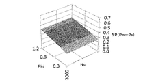
- FIG. 6 shows the theoretical value of the differential pressure ⁇ P required during the cooling operation
- FIG. 7 shows the theoretical value of the differential pressure ⁇ P required during the heating operation.
- the change characteristic of the differential pressure ⁇ P according to the injection pressure Pinj changes according to the rotational speed Nc.
- the differential pressure ⁇ P decreases as the rotational speed Nc increases.
- the differential pressure ⁇ P during the cooling operation is slightly lower than the differential pressure ⁇ P during the heating operation.
- the back pressure adjusting valve 400 increases or decreases the opening of the pressure supply passage L3 according to at least the suction pressure Ps, the discharge pressure Pd, the injection pressure Pinj, and the back pressure Pm, and the differential pressure ⁇ P shown in FIGS. Control to be
- FIG. 8 shows a first embodiment of a back pressure adjustment valve 400 that adjusts the flow rate of lubricating oil supplied to the back pressure chamber H4.
- the back pressure adjusting valve 400 includes a valve housing 410 having a substantially stepped cylindrical shape, a valve unit 420 inserted in the valve housing 410, a bellows assembly 430 that urges the valve unit 420 in the valve closing direction, have.
- the bellows assembly 430 is an example of an elastic body.
- the large-diameter portion of the valve housing 410 has a substantially cylindrical discharge pressure introduction chamber H6, a first pressure-sensitive chamber H7, a second pressure-sensitive chamber H8, and a substantially stepped shape along a direction away from the small-diameter portion.
- a third pressure sensing chamber H9 having a cylindrical shape is formed.
- the discharge pressure introduction chamber H6 is connected to the pressure supply passage L3 on the discharge chamber H2 side via a plurality of first communication holes 410A formed in the peripheral wall of the large diameter portion of the valve housing 410.
- the first pressure sensing chamber H7 is connected to the pressure supply passage L3 on the back pressure chamber H4 side via a plurality of second communication holes 410B formed in the peripheral wall of the large diameter portion of the valve housing 410.
- the second pressure sensing chamber H8 is connected to the injection pressure sensing passage L7 via a plurality of third communication holes 410C formed in the peripheral wall of the large diameter portion of the valve housing 410.
- the third pressure sensing chamber H9 is connected to the suction pressure sensing passage L5 via a fourth communication hole 410D formed in the peripheral wall of the large diameter portion of the valve housing 410.
- valve back pressure chamber H10 having a substantially cylindrical shape is formed in the small diameter portion of the valve housing 410.
- the valve back pressure chamber H10 is connected to a suction pressure sensing branch passage L5A branched from the suction pressure sensing passage L5 via a fifth communication hole 410E formed at the tip of the small diameter portion of the valve housing 410.
- the valve unit 420 includes a valve shaft 422 having a substantially cylindrical shape, a first valve body 424 having a substantially disk shape, and a second valve body 426 having a substantially cylindrical shape.
- the first valve body 424 and the second valve body 426 are integrated with the valve shaft 422 at a central portion in the axial direction with a predetermined interval.
- the outer diameter of the first valve body 424 is formed larger than the outer diameter of the second valve body 426.
- the 1st valve body 424 is mentioned as an example of a valve body.
- the first valve body 424 of the valve unit 420 is located in the first pressure sensing chamber H7, and the second valve body 426 is connected to the second pressure sensing chamber H8 and the third pressure sensing chamber.
- the valve unit 420 is disposed so as to be capable of reciprocating in the axial direction while penetrating the partition wall with the chamber H9. Further, a sixth communication hole 410F having an inner diameter larger than the outer diameter of the valve shaft 422 of the valve unit 420 is formed in the partition wall between the discharge pressure introduction chamber H6 and the first pressure sensing chamber H7 of the valve housing 410.
- valve unit 420 moves from the valve closing position to the valve opening direction, the distance between the partition wall and the first valve body 424 changes, and the first feeling is detected from the discharge pressure introduction chamber H6 via the sixth communication hole 410F.
- the flow rate of the lubricating oil for back pressure adjustment supplied while reducing the pressure to the pressure chamber H7 can be changed.
- a bellows assembly 430 that biases the first valve body 424 in the valve closing direction via the valve shaft 422 of the valve unit 420 is disposed.
- the bellows assembly 430 includes an axially expandable bellows 432, a coil spring 434 housed in the bellows 432, a first cap 436 that closes one end opening in the axial direction of the bellows 432, and a shaft of the bellows 432. And a second cap 438 that fits into the small diameter portion of the third pressure sensing chamber H9 while closing the other end opening in the direction.
- the one end part of the valve shaft 422 of the valve unit 420 is fitted in the recessed part 436A formed in the center part of the 1st cap 436 so that contact / separation is possible.
- a coil spring 440 that biases the first valve body 424 in the valve opening direction via the valve shaft 422 of the valve unit 420 is disposed.
- the back pressure adjusting valve 400 appropriately sets the pressure receiving area of each part of the valve unit 420, the pressure receiving area and spring constant of the bellows assembly 430, the spring constant of the coil spring 440, etc., as shown in FIG. 13 (during cooling operation). And it comes to have the operation characteristic shown in FIG. 14 (at the time of heating operation). Referring to these operating characteristics, it will be understood that the back pressure adjusting valve 400 adjusts the back pressure Pm of the back pressure chamber H4 in accordance with the injection pressure Pinj in addition to the suction pressure Ps and the discharge pressure Pd. For this reason, in the scroll compressor 200 to which the injection cycle is applied, the back pressure can be optimized.
- the back pressure adjusting valve 400 causes the first valve body 424, which is biased in the valve closing direction by the back pressure Pm of the bellows assembly 430 and the back pressure chamber H4, by the suction pressure Ps, the discharge pressure Pd, and the injection pressure Pinj. Move in the valve opening direction.
- the back pressure adjusting valve 400 adjusts the back pressure Pm of the back pressure chamber H4 by increasing or decreasing the flow rate of supplying the lubricating oil separated from the gas refrigerant compressed in the compression chamber H3 to the back pressure chamber H4. .
- FIG. 15 shows a second embodiment of the back pressure adjusting valve 400 that adjusts the flow rate of the lubricating oil supplied to the back pressure chamber H4 on the outlet side (downstream side) of the back pressure chamber H4.
- the first communication hole 410A and the fourth communication hole 410D of the back pressure adjusting valve 400 return the back pressure adjusting lubricating oil from the back pressure chamber H4 to the suction chamber H1. It is provided in the middle of the passage L4.
- the back pressure adjusting valve 400 includes a valve housing 410 having a substantially stepped cylindrical shape, a valve unit 420 inserted in the valve housing 410, a bellows assembly 430 that urges the valve unit 420 in the valve opening direction, have.
- the bellows assembly 430 is an example of an elastic body.
- the large-diameter portion of the valve housing 410 has a substantially cylindrical discharge pressure introduction chamber H6, a first pressure-sensitive chamber H7, a second pressure-sensitive chamber H8, and a substantially stepped shape along a direction away from the small-diameter portion.
- a third pressure sensing chamber H9 having a cylindrical shape is formed.
- the discharge pressure introduction chamber H6 is connected to the pressure supply passage L3 on the discharge chamber H2 side via a plurality of first communication holes 410A formed in the peripheral wall of the large diameter portion of the valve housing 410.
- the first pressure sensing chamber H7 is connected to the injection pressure sensing passage L7 via a plurality of second communication holes 410B formed in the peripheral wall of the large diameter portion of the valve housing 410.
- the second pressure sensing chamber H8 is connected to the suction pressure sensing passage L5 via a plurality of third communication holes 410C formed in the peripheral wall of the large diameter portion of the valve housing 410.
- the third pressure sensing chamber H9 is connected to the pressure supply passage L3 on the back pressure chamber H4 side via a fourth communication hole 410D formed in the peripheral wall of the large diameter portion of the valve housing 410.
- valve back pressure chamber H10 having a substantially cylindrical shape is formed in the small diameter portion of the valve housing 410.
- the valve back pressure chamber H10 is connected to a suction pressure sensing branch passage L5A branched from the suction pressure sensing passage L5 via a fifth communication hole 410E formed at the tip of the small diameter portion of the valve housing 410.
- the valve unit 420 includes a valve shaft 422 having a substantially cylindrical shape, a first valve body 424 having a substantially cylindrical shape, a second valve body 426 having a substantially cylindrical shape, and a third valve body 428 having a substantially disk shape. And have.
- the first valve body 424, the second valve body 426, and the third valve body 428 are continuously integrated with the valve shaft 422 at the central portion in the axial direction thereof.
- the outer diameters of the first valve body 424, the second valve body 426, and the third valve body 428 are formed to increase in this order.
- the 3rd valve body 428 is mentioned as an example of a valve body.
- the first valve body 424 of the valve unit 420 passes through the partition wall between the discharge pressure introduction chamber H6 and the first pressure sensing chamber H7, and the second valve body 426 is the first.
- the valve unit 420 is disposed so as to be capable of reciprocating in the axial direction while passing through the partition wall between the pressure sensing chamber H7 and the second pressure sensing chamber H8 and the third valve body 428 is located in the second pressure sensing chamber H8.
- a sixth communication hole 410F having an inner diameter larger than the outer diameter of the valve shaft 422 of the valve unit 420 is formed in the partition wall between the second pressure sensing chamber H8 and the third pressure sensing chamber H9 of the valve housing 410. Yes.
- the valve unit 420 moves from the valve closing position in the valve opening direction, the distance between the partition wall and the third valve body 428 changes, and the second pressure sensing chamber H9 is connected to the second pressure sensing chamber H9 via the sixth communication hole 410F.
- the flow rate of the lubricating oil for back pressure adjustment that is returned to the pressure sensing chamber H8 while reducing the pressure can be changed.
- a bellows assembly 430 that urges the third valve body 428 in the valve opening direction via the valve shaft 422 of the valve unit 420 is disposed in the third pressure sensing chamber H9.
- the bellows assembly 430 includes an axially expandable bellows 432, a coil spring 434 housed in the bellows 432, a first cap 436 that closes one end opening in the axial direction of the bellows 432, and a shaft of the bellows 432. And a second cap 438 that fits into the small diameter portion of the third pressure sensing chamber H9 while closing the other end opening in the direction.
- the one end part of the valve shaft 422 of the valve unit 420 is fitted in the recessed part 436A formed in the center part of the 1st cap 436 so that contact / separation is possible.
- a coil spring 440 that urges the third valve body 428 in the valve closing direction via the valve shaft 422 of the valve unit 420 is disposed.
- the back pressure regulating valve 400 appropriately sets the pressure receiving area of each part of the valve unit 420, the pressure receiving area and spring constant of the bellows assembly 430, the spring constant of the coil spring 440, and the like as in the first embodiment.
- the operation characteristics shown in FIG. 13 (during cooling operation) and FIG. 14 (during heating operation) are obtained.
- the back pressure can be optimized.
- the back pressure regulating valve 400 causes the third valve body 428, which is biased in the valve opening direction by the back pressure Pm of the bellows assembly 430 and the back pressure chamber H4, by the suction pressure Ps, the discharge pressure Pd, and the injection pressure Pinj. Move in the valve closing direction.
- the back pressure adjusting valve 400 adjusts the back pressure Pm of the back pressure chamber H4 by increasing or decreasing the flow rate of supplying the lubricating oil separated from the gas refrigerant compressed in the compression chamber H3 to the back pressure chamber H4. .
- FIG. 20 shows a modification of the back pressure regulating valve 400 according to the first embodiment shown in FIG.
- the back pressure regulating valve 400 according to the modified example includes an electromagnetic actuator 450 in a small diameter portion of the valve housing 410 and is configured so that the valve unit 420 can be forcibly moved by the electromagnetic actuator 450.
- the back pressure adjusting valve 400 is provided with a control device 460 incorporating a microcomputer or the like in order to electronically control the electromagnetic actuator 450.
- the control device 460 includes a suction pressure sensor 470 that detects the suction pressure Ps, a discharge pressure sensor 480 that detects the discharge pressure Pd, an injection pressure sensor 490 that detects the injection pressure Pinj, a back pressure sensor 500 that detects the back pressure Pm,
- a suction pressure sensor 470 that detects the suction pressure Ps
- a discharge pressure sensor 480 that detects the discharge pressure Pd
- an injection pressure sensor 490 that detects the injection pressure Pinj
- a back pressure sensor 500 that detects the back pressure Pm
- Each output signal of the rotation speed sensor 510 that detects the rotation speed Nc of the scroll unit 220 is input.
- the back pressure regulating valve 400 according to the modification is mostly the same as that of the first embodiment, the description thereof is omitted by giving the same reference numerals (the same applies hereinafter).
- the control device 460 calculates the target back pressure Pc corresponding to the suction pressure Ps, the discharge pressure Pd, the injection pressure Pinj, and the rotational speed Nc, and calculates the back pressure Pm and the target back pressure Pc.
- An operation amount corresponding to the deviation e is output to the electromagnetic actuator 450. Therefore, the back pressure adjusting valve 400 according to the modified example forcibly corrects the displacement by the electromagnetic actuator 450 even if the back pressure Pm deviates from the target back pressure Pc by autonomous control. Accuracy can be improved.
- the operation amount for example, a current value, a voltage value, a duty ratio, or the like can be used.
- FIG. 22 shows an example of control contents of the electromagnetic actuator 450 that the control device 460 repeatedly executes at predetermined time intervals.
- step 1 abbreviated as “S1” in the figure, the same applies hereinafter
- the control device 460 performs suction from the suction pressure sensor 470, the discharge pressure sensor 480, the injection pressure sensor 490, the back pressure sensor 500, and the rotation speed sensor 510.
- the pressure Ps, discharge pressure Pd, injection pressure Pinj, back pressure Pm, and rotation speed Nc are read.
- a target back pressure as a target control value corresponding to the suction pressure, the discharge pressure, the injection pressure, and the rotation speed is set in advance so that the control device 460 realizes the operation characteristics shown in FIGS.
- the target back pressure Pc corresponding to the suction pressure Ps, the discharge pressure Pd, the injection pressure Pinj, and the rotational speed Nc is calculated with reference to the control map.
- the control map can be obtained through theory or experiment, for example.
- step 4 the control device 460 determines whether or not the absolute value of the deviation e is greater than a predetermined value.
- the predetermined value is a threshold value for determining whether or not the back pressure Pm has approached the target back pressure Pc, that is, whether or not the back pressure Pm has reached the target back pressure Pc by feedback control.
- the operating pressure of the back pressure regulating valve 400, the required accuracy of the back pressure, etc. can be set as appropriate. If control device 460 determines that the absolute value of deviation e is greater than the predetermined value (Yes), control proceeds to step 5. On the other hand, if control device 460 determines that the absolute value of deviation e is equal to or less than a predetermined value (No), it ends the process.
- step 5 the control device 460 outputs an operation amount corresponding to the deviation e to the electromagnetic actuator 450.
- step 6 the control device 460 reads the back pressure Pm from the back pressure sensor 500, and then returns the process to step 3.
- the back pressure regulating valve 400 has the operating characteristics shown in FIG. 23 (during cooling operation) and FIG. 24 (during heating operation). Referring to these operating characteristics, it is understood that the back pressure adjusting valve 400 adjusts the back pressure Pm of the back pressure chamber H4 according to the rotation speed Nc in addition to the suction pressure Ps, the discharge pressure Pd, and the injection pressure Pinj. Let's do it. For this reason, the control accuracy of the flow rate of the lubricating oil supplied to the back pressure chamber H4 of the scroll compressor 200 is improved, and the deviation between the back pressure Pm and the target back pressure Pc can be reduced.
- the back pressure regulating valve 400 including the electromagnetic actuator 450 controls the flow rate on the outlet side of the back pressure chamber H4, and the back pressure regulating valve 400 according to the second embodiment (see FIG. 15). Can also be assumed.
- movement and effect of this back pressure adjustment valve 400 are the same as that of the back pressure adjustment valve 400 which concerns on a modification, the description is abbreviate
- the target back pressure Pc corresponding to the suction pressure Ps, the discharge pressure Pd, and the injection pressure Pinj can be calculated without using the rotational speed Nc. . In this way, it is possible to realize a characteristic with better control accuracy than the autonomous back pressure regulating valve 400 while suppressing an increase in control load.
- the back pressure regulating valve 400 for example, a known flow control valve in which a valve body is directly driven by an electromagnetic actuator can be used. In this case, the back pressure adjustment valve 400 is electronically controlled according to the control content shown in FIG.
- Refrigeration cycle (refrigerant circuit) 200 Scroll compressor 220 Scroll unit 222 Fixed scroll 224 Orbiting scroll 400 Back pressure regulating valve 424 First valve body (valve body) 428 Third valve element (valve element) 430 Bellows assembly (elastic body) 450 Electromagnetic actuator 460 Control device 470 Suction pressure sensor 480 Discharge pressure sensor 490 Injection pressure sensor 500 Back pressure sensor 510 Rotational speed sensor H3 Compression chamber H4 Back pressure chamber L3 Pressure supply passage L4 Pressure release passage
Abstract
[Problem] In a scroll compressor to which an injection cycle is applied, to optimize a back pressure which presses an orbiting scroll toward a fixed scroll.
[Solution] A back pressure regulating valve (400) which regulates a back pressure (Pm) in a back pressure chamber (H4) regulates, in accordance with a suction intake pressure (Ps) of a suction intake chamber (H1), a discharge pressure (Pd) of a discharge chamber (H2), and an injection pressure (Pinj), the degree of opening of a first valve body (424) which increases or decreases the flow rate, to the back pressure chamber (H4), of lubricating oil that has been separated from a gaseous refrigerant compressed in a compression chamber. Furthermore, the back pressure regulating valve (400) increases or decreases the flow rate of the lubricating oil in accordance also with the injection pressure (Pinj), in addition to the suction intake pressure (Ps) and the discharge pressure (Pd), and regulates the back pressure to a target back pressure that varies in accordance with the injection pressure (Pinj).
Description
本発明は、冷凍サイクルにおける冷媒を圧縮するスクロール圧縮機に関する。
The present invention relates to a scroll compressor that compresses refrigerant in a refrigeration cycle.
スクロール圧縮機は、互いに噛み合わされる固定スクロール及び旋回スクロールを有する、スクロールユニットを備えている。スクロールユニットは、旋回スクロールが固定スクロールの軸心周りに公転することで、固定スクロールと旋回スクロールとにより区画される圧縮室の容積を増減し、気体冷媒を圧縮して吐出する。スクロール圧縮機では、旋回スクロールの背面に背圧を作用させて固定スクロールに押し付けることで、圧縮運転中に旋回スクロールが固定スクロールから離れることを抑制し、圧縮不良を発生し難くしている。このとき、旋回スクロールの背面に作用させる背圧は、国際公開第2012/147145号パンフレット(特許文献1)に記載されるように、気体冷媒の吸入圧力及び吐出圧力に基づいて調整されている。
The scroll compressor includes a scroll unit having a fixed scroll and a turning scroll that are meshed with each other. The scroll unit revolves around the axis of the fixed scroll to increase or decrease the volume of the compression chamber defined by the fixed scroll and the orbiting scroll, and compresses and discharges the gas refrigerant. In the scroll compressor, the back pressure is applied to the back surface of the orbiting scroll and pressed against the fixed scroll, so that the orbiting scroll is prevented from being separated from the fixed scroll during the compression operation, thereby making it difficult to cause a compression failure. At this time, the back pressure applied to the back surface of the orbiting scroll is adjusted based on the suction pressure and the discharge pressure of the gaseous refrigerant as described in International Publication No. 2012/147145 pamphlet (Patent Document 1).
ところで、近年では、成績係数COP(Coefficient Of Performance)を向上させるため、ガスインジェクションサイクルを適用したスクロール圧縮機が実用化されている。ガスインジェクションサイクルは、圧縮機、凝縮器、第1膨張弁、気液分離器、第2膨張弁及び蒸発器をこの順番で配設した冷媒回路において、気液分離器で分離された気体冷媒を圧縮機の圧縮室にインジェクションして冷凍効果を改善する。
Incidentally, in recent years, a scroll compressor to which a gas injection cycle is applied has been put into practical use in order to improve the coefficient of performance COP (Coefficient Of Performance). The gas injection cycle is a refrigerant circuit in which a compressor, a condenser, a first expansion valve, a gas-liquid separator, a second expansion valve, and an evaporator are arranged in this order, and gas refrigerant separated by the gas-liquid separator is removed. The refrigeration effect is improved by injection into the compressor chamber.
しかしながら、このようなガスインジェクションサイクルを適用したスクロール圧縮機では、気体冷媒を圧縮室にインジェクションすることから、圧縮室にインジェクションする気体冷媒の圧力(インジェクション圧力)に応じて目標背圧が変化する。具体的には、インジェクション圧力が高い場合には、背圧が不足して旋回スクロールを固定スクロールに押し付ける力が弱くなり、例えば、圧縮室から気体冷媒が漏れて、圧縮効率が低下してしまうおそれがある。一方、インジェクション圧力が低い場合には、背圧が過剰となって、例えば、旋回スクロールを公転させる動力が大きくなり、圧縮効率の低下やスクロールのラップのかじりなどが発生してしまうおそれがある。
However, in the scroll compressor to which such a gas injection cycle is applied, since the gaseous refrigerant is injected into the compression chamber, the target back pressure changes according to the pressure of the gaseous refrigerant injected into the compression chamber (injection pressure). Specifically, when the injection pressure is high, the back pressure is insufficient and the force for pressing the orbiting scroll against the fixed scroll is weakened. For example, the gas refrigerant may leak from the compression chamber and the compression efficiency may be reduced. There is. On the other hand, when the injection pressure is low, the back pressure becomes excessive, and for example, the power for revolving the orbiting scroll is increased, which may cause a reduction in compression efficiency and galling of the scroll wrap.
そこで、本発明は、インジェクションサイクルを適用したスクロール圧縮機において、背圧の適正化を図ることを目的とする。
Therefore, an object of the present invention is to optimize the back pressure in a scroll compressor to which an injection cycle is applied.
このため、スクロール圧縮機は、固定スクロール及び旋回スクロールにより区画される圧縮室の容積を増減すると共に、冷媒回路の途中から取り出された気体冷媒を圧縮室にインジェクションし、気体冷媒を吸入、圧縮及び吐出するスクロールユニットと、旋回スクロールを固定スクロールに向けて押し付ける背圧室の圧力を、圧縮室に吸入される気体冷媒の吸入圧力、圧縮室から吐出される気体冷媒の吐出圧力、及び、圧縮室にインジェクションされる気体冷媒のインジェクション圧力に応じて調整する背圧調整弁と、を有する。
For this reason, the scroll compressor increases or decreases the volume of the compression chamber partitioned by the fixed scroll and the orbiting scroll, and injects the gaseous refrigerant taken out from the middle of the refrigerant circuit into the compression chamber, sucks, compresses and compresses the gaseous refrigerant. The pressure of the scroll unit for discharging and the pressure of the back pressure chamber that presses the orbiting scroll toward the fixed scroll, the suction pressure of the gas refrigerant sucked into the compression chamber, the discharge pressure of the gas refrigerant discharged from the compression chamber, and the compression chamber And a back pressure adjusting valve that adjusts according to the injection pressure of the gaseous refrigerant injected into the.
本発明によれば、インジェクションサイクルを適用したスクロール圧縮機において、背圧の適正化を図ることができる。
According to the present invention, it is possible to optimize the back pressure in the scroll compressor to which the injection cycle is applied.
以下、添付された図面を参照し、本発明を実施するための実施形態について詳述する。
図1は、本実施形態の前提となる、ガスインジェクションサイクルを適用した冷凍サイクル100の一例を示す。ここで、冷凍サイクル100が、冷凍回路の一例として挙げられる。 Hereinafter, embodiments for carrying out the present invention will be described in detail with reference to the accompanying drawings.
FIG. 1 shows an example of arefrigeration cycle 100 to which a gas injection cycle is applied, which is a premise of the present embodiment. Here, the refrigeration cycle 100 is mentioned as an example of a refrigeration circuit.
図1は、本実施形態の前提となる、ガスインジェクションサイクルを適用した冷凍サイクル100の一例を示す。ここで、冷凍サイクル100が、冷凍回路の一例として挙げられる。 Hereinafter, embodiments for carrying out the present invention will be described in detail with reference to the accompanying drawings.
FIG. 1 shows an example of a
冷凍サイクル100は、冷媒が循環する冷媒配管110に対して、圧縮機120、凝縮器130、第1膨張弁140、気液分離器150、第2膨張弁160及び蒸発器170をこの順番で配設して構成されている。圧縮機120は、低温・低圧の気体冷媒を圧縮して高温・高圧の気体冷媒にする。凝縮器130は、圧縮機120を通過した高温・高圧の気体冷媒を冷却して高圧・低温の液体冷媒にする。第1膨張弁140及び第2膨張弁160は、低温・高圧の液体冷媒を2段階で減圧して低温・低圧の液体冷媒にする。蒸発器170は、低温・低圧の液体冷媒を気化させて低温・低圧の気体冷媒にする。また、気液分離器150は、第1膨張弁140で減圧された中間圧の液体冷媒から気体冷媒を分離し、これをインジェクションガスとして圧縮機120へと供給する。
In the refrigeration cycle 100, the compressor 120, the condenser 130, the first expansion valve 140, the gas-liquid separator 150, the second expansion valve 160, and the evaporator 170 are arranged in this order with respect to the refrigerant pipe 110 through which the refrigerant circulates. It is configured. The compressor 120 compresses the low-temperature / low-pressure gas refrigerant into a high-temperature / high-pressure gas refrigerant. The condenser 130 cools the high-temperature / high-pressure gaseous refrigerant that has passed through the compressor 120 to form a high-pressure / low-temperature liquid refrigerant. The first expansion valve 140 and the second expansion valve 160 depressurize the low-temperature / high-pressure liquid refrigerant in two stages to form a low-temperature / low-pressure liquid refrigerant. The evaporator 170 vaporizes the low-temperature / low-pressure liquid refrigerant into a low-temperature / low-pressure gas refrigerant. Further, the gas-liquid separator 150 separates the gaseous refrigerant from the intermediate-pressure liquid refrigerant decompressed by the first expansion valve 140, and supplies this to the compressor 120 as an injection gas.
図2は、ガスインジェクションサイクルのモリエル線図を示す。
凝縮器130を通過した高圧Phの液体冷媒は、第1膨張弁140で中間圧のインジェクション圧力Pinjまで減圧されて気液二相となり、気液分離器150へと導入される。気液分離器150では、入口の状態がA点で、内部でB点の飽和気体冷媒とC点の飽和液体冷媒に分離される。その後、飽和液体冷媒は、第2膨張弁160でさらに減圧されて低圧Plとなり、蒸発器170へと導入される。蒸発器170では、外気と熱交換することで、低圧Plの液体冷媒が気化して気体冷媒となり、圧縮機120へと導入される。一方、インジェクション圧力Pinjの飽和気体冷媒は、圧縮機120の圧縮室にインジェクションされる。 FIG. 2 shows a Mollier diagram of the gas injection cycle.
The high-pressure Ph liquid refrigerant that has passed through thecondenser 130 is reduced to an intermediate injection pressure Pinj by the first expansion valve 140 to become a gas-liquid two-phase, and is introduced into the gas-liquid separator 150. In the gas-liquid separator 150, the state of the inlet is point A, and it is separated into saturated gas refrigerant at point B and saturated liquid refrigerant at point C inside. Thereafter, the saturated liquid refrigerant is further depressurized by the second expansion valve 160 to become a low pressure Pl and introduced into the evaporator 170. The evaporator 170 exchanges heat with the outside air, whereby the low-pressure Pl liquid refrigerant is vaporized to become a gaseous refrigerant and introduced into the compressor 120. On the other hand, the saturated gas refrigerant having the injection pressure Pinj is injected into the compression chamber of the compressor 120.
凝縮器130を通過した高圧Phの液体冷媒は、第1膨張弁140で中間圧のインジェクション圧力Pinjまで減圧されて気液二相となり、気液分離器150へと導入される。気液分離器150では、入口の状態がA点で、内部でB点の飽和気体冷媒とC点の飽和液体冷媒に分離される。その後、飽和液体冷媒は、第2膨張弁160でさらに減圧されて低圧Plとなり、蒸発器170へと導入される。蒸発器170では、外気と熱交換することで、低圧Plの液体冷媒が気化して気体冷媒となり、圧縮機120へと導入される。一方、インジェクション圧力Pinjの飽和気体冷媒は、圧縮機120の圧縮室にインジェクションされる。 FIG. 2 shows a Mollier diagram of the gas injection cycle.
The high-pressure Ph liquid refrigerant that has passed through the
次に、ガスインジェクションサイクルを構成する圧縮機120の一例として、固定スクロール及び旋回スクロールにより気体冷媒を圧縮するスクロール圧縮機200について説明する。
Next, as an example of the compressor 120 constituting the gas injection cycle, a scroll compressor 200 that compresses a gaseous refrigerant using a fixed scroll and a turning scroll will be described.
図3は、スクロール圧縮機200の一例を示す。
スクロール圧縮機200は、スクロールユニット220と、気体冷媒の吸入室H1及び吐出室H2を有するハウジング240と、スクロールユニット220を駆動させる駆動部としての電動モータ260と、電動モータ260の駆動制御用のインバータ280と、を備えている。なお、インバータ280は、スクロール圧縮機200に組み込まれていなくてもよい。 FIG. 3 shows an example of thescroll compressor 200.
Thescroll compressor 200 includes a scroll unit 220, a housing 240 having a gas refrigerant suction chamber H <b> 1 and a discharge chamber H <b> 2, an electric motor 260 as a drive unit that drives the scroll unit 220, and drive control for the electric motor 260. And an inverter 280. Note that the inverter 280 may not be incorporated in the scroll compressor 200.
スクロール圧縮機200は、スクロールユニット220と、気体冷媒の吸入室H1及び吐出室H2を有するハウジング240と、スクロールユニット220を駆動させる駆動部としての電動モータ260と、電動モータ260の駆動制御用のインバータ280と、を備えている。なお、インバータ280は、スクロール圧縮機200に組み込まれていなくてもよい。 FIG. 3 shows an example of the
The
スクロールユニット220は、互いに噛み合わされる固定スクロール222及び旋回スクロール224を有している。固定スクロール222は、円板形状の底板222Aと、底板222Aの一面から立設するインボリュート形状(渦巻き形状)のラップ222Bと、を含んでいる。旋回スクロール224は、固定スクロール222と同様に、円板形状の底板224Aと、底板224Aの一面から立設するインボリュート形状のラップ224Bと、を含んでいる。
The scroll unit 220 includes a fixed scroll 222 and a turning scroll 224 that are meshed with each other. The fixed scroll 222 includes a disc-shaped bottom plate 222A and an involute-shaped (spiral shape) wrap 222B standing from one surface of the bottom plate 222A. Similar to the fixed scroll 222, the orbiting scroll 224 includes a disc-shaped bottom plate 224A and an involute-shaped wrap 224B standing from one surface of the bottom plate 224A.
固定スクロール222及び旋回スクロール224は、そのラップ222B及び224Bを噛み合わせるように配置されている。詳細には、固定スクロール222のラップ222Bの先端部が、旋回スクロール224の底板224Aの一面に接触し、旋回スクロール224のラップ224Bの先端部が、固定スクロール222の底板222Aの一面に接触するように配置されている。なお、ラップ222B及び224Bの先端部には、チップシール(図示せず)が取り付けられている。
The fixed scroll 222 and the orbiting scroll 224 are arranged so that the wraps 222B and 224B are engaged with each other. Specifically, the tip of the wrap 222B of the fixed scroll 222 is in contact with one surface of the bottom plate 224A of the orbiting scroll 224, and the tip of the wrap 224B of the orbiting scroll 224 is in contact with one surface of the bottom plate 222A of the fixed scroll 222. Is arranged. A tip seal (not shown) is attached to the tip of the wraps 222B and 224B.
また、固定スクロール222及び旋回スクロール224は、そのラップ222B及び224Bの周方向の角度が互いにずれた状態で、そのラップ222B及び224Bの側壁が互いに部分的に接触するように配置されている。従って、固定スクロール222のラップ222Bと旋回スクロール224のラップ224Bとの間には、圧縮室H3として機能する、三日月形状の密閉空間が形成されている。
Further, the fixed scroll 222 and the orbiting scroll 224 are arranged so that the side walls of the wraps 222B and 224B are partially in contact with each other with the circumferential angles of the wraps 222B and 224B being shifted from each other. Therefore, a crescent-shaped sealed space that functions as the compression chamber H3 is formed between the wrap 222B of the fixed scroll 222 and the wrap 224B of the orbiting scroll 224.
旋回スクロール224は、その自転が阻止された状態で、後述するクランク機構を介して、固定スクロール222の軸心周りに公転可能に配置されている。従って、スクロールユニット220は、固定スクロール222のラップ222Bと旋回スクロール224のラップ224Bとにより区画される圧縮室H3を中央部に移動させ、その容積を徐々に減少させる。その結果、スクロールユニット220は、ラップ222B及び224Bの外端部から圧縮室H3に吸入される気体冷媒を圧縮する。
The orbiting scroll 224 is disposed so as to be able to revolve around the axis of the fixed scroll 222 via a crank mechanism which will be described later in a state in which the rotation is prevented. Therefore, the scroll unit 220 moves the compression chamber H3 defined by the wrap 222B of the fixed scroll 222 and the wrap 224B of the orbiting scroll 224 to the center, and gradually reduces the volume thereof. As a result, the scroll unit 220 compresses the gaseous refrigerant sucked into the compression chamber H3 from the outer ends of the wraps 222B and 224B.
ハウジング240は、電動モータ260及びインバータ280を収容するフロントハウジング242と、スクロールユニット220を収容するセンターハウジング244と、リアハウジング246と、インバータカバー248と、を有している。そして、フロントハウジング242、センターハウジング244、リアハウジング246及びインバータカバー248が、例えば、ボルト及びワッシャを含む締結具(図示せず)によって、一体的に締結されることで、スクロール圧縮機200のハウジング240が構成されている。
The housing 240 includes a front housing 242 that houses the electric motor 260 and the inverter 280, a center housing 244 that houses the scroll unit 220, a rear housing 246, and an inverter cover 248. The front housing 242, the center housing 244, the rear housing 246, and the inverter cover 248 are integrally fastened by, for example, a fastener (not shown) including a bolt and a washer, so that the housing of the scroll compressor 200 is obtained. 240 is configured.
フロントハウジング242は、略円筒形状の周壁部242Aと仕切壁部242Bとを有している。フロントハウジング242の内部空間は、仕切壁部242Bにより、電動モータ260を収容するための空間とインバータ280を収容するための空間とに仕切られている。周壁部242Aの一端側(図3では下側)の開口は、インバータカバー248によって閉止されている。また、周壁部242Aの他端側(図3では上側)の開口は、センターハウジング244によって閉止されている。仕切壁部242Bには、その径方向の中央部に後述する駆動軸266の一端部を回転自由に支持する、略円筒形状の支持部242B1が、周壁部242Aの他端側に向かって突設されている。
The front housing 242 has a substantially cylindrical peripheral wall portion 242A and a partition wall portion 242B. The internal space of the front housing 242 is partitioned into a space for housing the electric motor 260 and a space for housing the inverter 280 by the partition wall portion 242B. The opening on one end side (the lower side in FIG. 3) of the peripheral wall portion 242 </ b> A is closed by the inverter cover 248. Further, the opening on the other end side (upper side in FIG. 3) of the peripheral wall portion 242A is closed by the center housing 244. The partition wall portion 242B has a substantially cylindrical support portion 242B1 that rotatably supports one end portion of a drive shaft 266, which will be described later, at the center portion in the radial direction, and protrudes toward the other end side of the peripheral wall portion 242A. Has been.
また、フロントハウジング242の周壁部242A及び仕切壁部242Bとセンターハウジング244とにより、気体冷媒の吸入室H1が区画されている。吸入室H1には、周壁部242Aに形成された吸入ポートP1を介して、低圧・低温の気体冷媒が吸入される。なお、吸入室H1では、気体冷媒が電動モータ260の周囲を流通して電動モータ260を冷却可能になっており、電動モータ260の上側の空間とその下側の空間とが連通する、1つの吸入室H1が形成されている。吸入室H1には、回転駆動される駆動軸266などの摺動部位の潤滑のため、適量の潤滑油が貯留されている。このため、吸入室H1においては、気体冷媒は潤滑油との混合流体として流れている。
In addition, a suction chamber H1 for gaseous refrigerant is defined by the peripheral wall portion 242A and the partition wall portion 242B of the front housing 242 and the center housing 244. Low-pressure and low-temperature gaseous refrigerant is sucked into the suction chamber H1 through a suction port P1 formed in the peripheral wall portion 242A. In the suction chamber H1, gas refrigerant flows around the electric motor 260 to cool the electric motor 260, and the upper space of the electric motor 260 and the lower space communicate with each other. A suction chamber H1 is formed. An appropriate amount of lubricating oil is stored in the suction chamber H1 in order to lubricate sliding parts such as the drive shaft 266 that is rotationally driven. For this reason, in the suction chamber H1, the gaseous refrigerant flows as a mixed fluid with the lubricating oil.
センターハウジング244は、フロントハウジング242との締結側とは反対側が開口した略有底円筒形状をなし、その内部にスクロールユニット220を収容することができる。センターハウジング244は、円筒部244Aとその一端側の底壁部244Bとを有している。円筒部244Aと底壁部244Bとによって区画される空間に、スクロールユニット220が収容されている。円筒部244Aの他端側には、固定スクロール222が嵌合する嵌合部244A1が形成されている。従って、センターハウジング244の開口は、固定スクロール222によって閉止されている。また、底壁部244Bは、その径方向の中央部が電動モータ260に向かって膨出するように形成されている。底壁部244Bの膨出部244B1の径方向の中央部には、駆動軸266の他端部を貫通させるための貫通孔が形成されている。そして、膨出部244B1のスクロールユニット220側には、駆動軸266の他端部を回転自由に支持するベアリング300が嵌合する嵌合部が形成されている。
The center housing 244 has a substantially bottomed cylindrical shape opened on the side opposite to the fastening side with the front housing 242, and can accommodate the scroll unit 220 therein. The center housing 244 has a cylindrical portion 244A and a bottom wall portion 244B on one end side thereof. The scroll unit 220 is accommodated in a space defined by the cylindrical portion 244A and the bottom wall portion 244B. A fitting portion 244A1 into which the fixed scroll 222 is fitted is formed on the other end side of the cylindrical portion 244A. Therefore, the opening of the center housing 244 is closed by the fixed scroll 222. Further, the bottom wall portion 244 </ b> B is formed so that the central portion in the radial direction bulges toward the electric motor 260. A through hole for allowing the other end portion of the drive shaft 266 to pass therethrough is formed in the radial center portion of the bulging portion 244B1 of the bottom wall portion 244B. A fitting portion into which a bearing 300 that rotatably supports the other end portion of the drive shaft 266 is fitted is formed on the bulging portion 244B1 on the scroll unit 220 side.
センターハウジング244の底壁部244Bと旋回スクロール224の底板224Aとの間には、円環形状のスラストプレート310が配置されている。底壁部244Bの外周部は、スラストプレート310を介して旋回スクロール224からのスラスト力を受ける。底壁部244B及び底板224Aのスラストプレート310と当接する部位には、シール部材(図示せず)が夫々埋設されている。
An annular thrust plate 310 is disposed between the bottom wall portion 244B of the center housing 244 and the bottom plate 224A of the orbiting scroll 224. The outer peripheral portion of the bottom wall portion 244 </ b> B receives a thrust force from the orbiting scroll 224 through the thrust plate 310. Seal members (not shown) are respectively embedded in the portions of the bottom wall portion 244B and the bottom plate 224A that are in contact with the thrust plate 310.
また、底板224Aの電動モータ260側端面と底壁部244Bとの間、つまり、旋回スクロール224の固定スクロール222とは反対側の端面とセンターハウジング244との間には、背圧室H4が形成されている。センターハウジング244には、吸入室H1からスクロールユニット220のラップ222B及び224Bの外端部付近の空間H5へと気体冷媒(詳細には、気体冷媒と潤滑油との混合流体)を導入するための冷媒導入通路L1が形成されている。冷媒導入通路L1は、空間H5と吸入室H1とを連通しているため、空間H5の圧力は、吸入室H1の圧力(吸入圧力Ps)と等しい。
Further, a back pressure chamber H4 is formed between the end surface of the bottom plate 224A on the electric motor 260 side and the bottom wall portion 244B, that is, between the end surface of the orbiting scroll 224 opposite to the fixed scroll 222 and the center housing 244. Has been. A gas refrigerant (specifically, a mixed fluid of a gas refrigerant and lubricating oil) is introduced into the center housing 244 from the suction chamber H1 to the space H5 near the outer ends of the wraps 222B and 224B of the scroll unit 220. A refrigerant introduction passage L1 is formed. Since the refrigerant introduction passage L1 communicates the space H5 and the suction chamber H1, the pressure in the space H5 is equal to the pressure in the suction chamber H1 (suction pressure Ps).
リアハウジング246は、センターハウジング244の円筒部244Aの嵌合部244A1側端部に、締結具によって締結されている。従って、固定スクロール222は、その底板222Aが嵌合部244A1とリアハウジング246との間に挟持されて固定されている。また、リアハウジング246は、センターハウジング244との締結側が開口した略有底円筒形状をなし、円筒部246Aとその他端側の底壁部246Bとを有している。
The rear housing 246 is fastened to a fitting portion 244A1 side end portion of the cylindrical portion 244A of the center housing 244 by a fastener. Accordingly, the bottom plate 222A of the fixed scroll 222 is fixed while being sandwiched between the fitting portion 244A1 and the rear housing 246. Further, the rear housing 246 has a substantially bottomed cylindrical shape that is open on the fastening side with the center housing 244, and includes a cylindrical portion 246A and a bottom wall portion 246B on the other end side.
リアハウジング246の円筒部246A及び底壁部246Bと固定スクロール222の底板222Aとにより、気体冷媒の吐出室H2が区画されている。底板222Aの中央部には、圧縮冷媒の吐出通路(吐出孔)L2が形成され、吐出通路L2には、吐出室H2からスクロールユニット220への流れを規制する、例えば、リードバルブからなる逆止弁320が付設されている。吐出室H2には、スクロールユニット220の圧縮室H3で圧縮された圧縮冷媒が吐出通路L2及び逆止弁320を介して吐出される。吐出室H2の圧縮冷媒は、底壁部246Bに形成された吐出ポートP2を介して、凝縮器130へと吐出される。
The gas refrigerant discharge chamber H2 is partitioned by the cylindrical portion 246A and the bottom wall portion 246B of the rear housing 246 and the bottom plate 222A of the fixed scroll 222. A compressed refrigerant discharge passage (discharge hole) L2 is formed in the central portion of the bottom plate 222A, and the discharge passage L2 restricts the flow from the discharge chamber H2 to the scroll unit 220, for example, a check valve made of a reed valve. A valve 320 is attached. Compressed refrigerant compressed in the compression chamber H3 of the scroll unit 220 is discharged into the discharge chamber H2 through the discharge passage L2 and the check valve 320. The compressed refrigerant in the discharge chamber H2 is discharged to the condenser 130 via the discharge port P2 formed in the bottom wall portion 246B.
なお、図示を省略するが、リアハウジング246には、吐出室H2の圧縮冷媒から潤滑油を分離するためのオイルセパレータが配置されている。オイルセパレータにより潤滑油が分離された圧縮冷媒(微量の潤滑油が残存する場合もある)は、吐出ポートP2を介して凝縮器130へと吐出される。一方、オイルセパレータにより分離された潤滑油は、後述する圧力供給通路L3へと導かれる。図3では、潤滑油の混合前又は混合後の気体冷媒の流れは斜線付き矢印で示され、潤滑油と混合された気体冷媒(混合流体)の流れは太線矢印で示され、気体冷媒から分離された潤滑油の流れは白抜き矢印で示されている。ここで、圧力供給通路L3が、潤滑油を背圧室に供給する通路の一例として挙げられる。
Although not shown, the rear housing 246 is provided with an oil separator for separating the lubricating oil from the compressed refrigerant in the discharge chamber H2. The compressed refrigerant from which the lubricating oil has been separated by the oil separator (a small amount of lubricating oil may remain) is discharged to the condenser 130 via the discharge port P2. On the other hand, the lubricating oil separated by the oil separator is guided to a pressure supply passage L3 described later. In FIG. 3, the flow of the gaseous refrigerant before or after mixing the lubricating oil is indicated by the hatched arrow, and the flow of the gaseous refrigerant (mixed fluid) mixed with the lubricating oil is indicated by the thick line arrow, which is separated from the gaseous refrigerant. The flow of the lubricated oil is indicated by white arrows. Here, the pressure supply passage L3 is an example of a passage for supplying lubricating oil to the back pressure chamber.
電動モータ260は、例えば、三相交流モータからなり、ロータ262と、ロータ262の径方向外側に配置されるステータコアユニット264と、を有している。そして、例えば、車載のバッテリ(図示せず)からの直流電流が、インバータ280により交流電流に変換され、電動モータ260に供給される。
The electric motor 260 is made of, for example, a three-phase AC motor, and includes a rotor 262 and a stator core unit 264 disposed on the outer side in the radial direction of the rotor 262. For example, a direct current from an on-vehicle battery (not shown) is converted into an alternating current by an inverter 280 and supplied to the electric motor 260.
ロータ262は、その径方向中心に形成された軸孔に圧入される駆動軸266を介して、ステータコアユニット264の径方向内側で回転可能に支持されている。駆動軸266の一端部は、フロントハウジング242の支持部242B1に回転可能に支持されている。駆動軸266の他端部は、センターハウジング244に形成された貫通孔を貫通して、ベアリング300によって回転可能に支持されている。インバータ280からの給電により、ステータコアユニット264に磁界が発生すると、ロータ262に回転力が作用して駆動軸266が回転駆動される。駆動軸266の他端部は、クランク機構を介して、旋回スクロール224に連結されている。
The rotor 262 is rotatably supported on the radially inner side of the stator core unit 264 via a drive shaft 266 that is press-fitted into a shaft hole formed at the center in the radial direction. One end of the drive shaft 266 is rotatably supported by the support portion 242B1 of the front housing 242. The other end portion of the drive shaft 266 passes through a through hole formed in the center housing 244 and is rotatably supported by the bearing 300. When a magnetic field is generated in the stator core unit 264 by power feeding from the inverter 280, a rotational force acts on the rotor 262, and the drive shaft 266 is rotationally driven. The other end of the drive shaft 266 is connected to the orbiting scroll 224 via a crank mechanism.
クランク機構は、図4に示すように、旋回スクロール224の底板224Aの背圧室H4側端面に突出形成された円筒形状のボス部330と、駆動軸266の他端部に設けられたクランク340に偏心状態で取り付けられた偏心ブッシュ350と、を有している。偏心ブッシュ350は、ボス部330に回転可能に支持されている。なお、駆動軸266の他端部(クランク340側端部)には、旋回スクロール224の動作時の遠心力に対抗するバランサウェイト360が取り付けられている。従って、旋回スクロール224は、その自転が阻止された状態で、クランク機構を介して、固定スクロール222の軸心周りに公転可能になっている。
As shown in FIG. 4, the crank mechanism includes a cylindrical boss portion 330 protruding from the end surface on the back pressure chamber H4 side of the bottom plate 224A of the orbiting scroll 224, and a crank 340 provided at the other end portion of the drive shaft 266. And an eccentric bush 350 attached in an eccentric state. The eccentric bush 350 is rotatably supported by the boss portion 330. Note that a balancer weight 360 is attached to the other end portion of the drive shaft 266 (the end portion on the crank 340 side) to counter the centrifugal force during the operation of the orbiting scroll 224. Therefore, the orbiting scroll 224 can revolve around the axis of the fixed scroll 222 via the crank mechanism in a state in which the rotation is prevented.
図5は、スクロール圧縮機200における、気体冷媒の流れを説明するためのブロック図である。
図3及び図5に示すように、蒸発器170からの低圧・低温の気体冷媒は、吸入ポートP1を介して吸入室H1に導入され、その後、冷媒導入通路L1を介してスクロールユニット220の外端部付近の空間H5に導かれる。そして、空間H5の気体冷媒は、スクロールユニット220の圧縮室H3に取り込まれて圧縮される。圧縮室H3で圧縮された圧縮冷媒は、吐出通路L2及び逆止弁320を経由して吐出室H2に吐出され、その後、吐出室H2から吐出ポートP2を介して凝縮器130へと吐出される。このようにして、吸入室H1を介して流入される気体冷媒を圧縮室H3で圧縮し、この圧縮冷媒を吐出室H2を介して吐出するスクロールユニット220が構成される。 FIG. 5 is a block diagram for explaining the flow of the gaseous refrigerant in thescroll compressor 200.
As shown in FIGS. 3 and 5, the low-pressure / low-temperature gas refrigerant from theevaporator 170 is introduced into the suction chamber H1 through the suction port P1, and then the outside of the scroll unit 220 through the refrigerant introduction passage L1. It is guided to a space H5 near the end. The gaseous refrigerant in the space H5 is taken into the compression chamber H3 of the scroll unit 220 and compressed. The compressed refrigerant compressed in the compression chamber H3 is discharged to the discharge chamber H2 via the discharge passage L2 and the check valve 320, and then discharged from the discharge chamber H2 to the condenser 130 via the discharge port P2. . In this way, the scroll unit 220 is configured to compress the gaseous refrigerant flowing in through the suction chamber H1 in the compression chamber H3 and discharge the compressed refrigerant through the discharge chamber H2.
図3及び図5に示すように、蒸発器170からの低圧・低温の気体冷媒は、吸入ポートP1を介して吸入室H1に導入され、その後、冷媒導入通路L1を介してスクロールユニット220の外端部付近の空間H5に導かれる。そして、空間H5の気体冷媒は、スクロールユニット220の圧縮室H3に取り込まれて圧縮される。圧縮室H3で圧縮された圧縮冷媒は、吐出通路L2及び逆止弁320を経由して吐出室H2に吐出され、その後、吐出室H2から吐出ポートP2を介して凝縮器130へと吐出される。このようにして、吸入室H1を介して流入される気体冷媒を圧縮室H3で圧縮し、この圧縮冷媒を吐出室H2を介して吐出するスクロールユニット220が構成される。 FIG. 5 is a block diagram for explaining the flow of the gaseous refrigerant in the
As shown in FIGS. 3 and 5, the low-pressure / low-temperature gas refrigerant from the
ここで、図3に示すように、スクロール圧縮機200は、背圧室H4の圧力調整用の背圧調整弁400を更に備えている。
背圧調整弁400は、吸入室H1の吸入圧力Ps、吐出室H2の吐出圧力Pd及びインジェクション圧力Pinjに応じて作動し、背圧室H4の背圧Pmが吸入圧力Ps、吐出圧力Pd及びインジェクション圧力Pinjに応じた目標背圧Pcに近づくように、その弁開度を自動的に調整する機械式(自律式)の流量制御弁である。背圧調整弁400は、リアハウジング246の底壁部246Bにおいて、電動モータ260の駆動軸266の中心軸と直交する方向に延びるように形成された収容室246Cに収容されている。背圧調整弁400の構造及び背圧調整動作については後述する。 Here, as shown in FIG. 3, thescroll compressor 200 further includes a back pressure adjusting valve 400 for adjusting the pressure of the back pressure chamber H4.
The backpressure adjusting valve 400 operates in accordance with the suction pressure Ps of the suction chamber H1, the discharge pressure Pd of the discharge chamber H2, and the injection pressure Pinj. This is a mechanical (autonomous) flow control valve that automatically adjusts the valve opening so as to approach the target back pressure Pc corresponding to the pressure Pinj. The back pressure adjustment valve 400 is accommodated in an accommodation chamber 246 </ b> C formed in the bottom wall portion 246 </ b> B of the rear housing 246 so as to extend in a direction orthogonal to the central axis of the drive shaft 266 of the electric motor 260. The structure of the back pressure adjustment valve 400 and the back pressure adjustment operation will be described later.
背圧調整弁400は、吸入室H1の吸入圧力Ps、吐出室H2の吐出圧力Pd及びインジェクション圧力Pinjに応じて作動し、背圧室H4の背圧Pmが吸入圧力Ps、吐出圧力Pd及びインジェクション圧力Pinjに応じた目標背圧Pcに近づくように、その弁開度を自動的に調整する機械式(自律式)の流量制御弁である。背圧調整弁400は、リアハウジング246の底壁部246Bにおいて、電動モータ260の駆動軸266の中心軸と直交する方向に延びるように形成された収容室246Cに収容されている。背圧調整弁400の構造及び背圧調整動作については後述する。 Here, as shown in FIG. 3, the
The back
スクロール圧縮機200は、図3及び図5に示すように、冷媒導入通路L1及び吐出通路L2に加えて、圧力供給通路L3、放圧通路L4、吸入圧力感知通路L5、インジェクションガス導入通路L6及びインジェクション圧力感知通路L7を備えている。ここで、放圧通路L4が、潤滑油を背圧室から排出する通路の一例として挙げられる。
As shown in FIGS. 3 and 5, the scroll compressor 200 includes a pressure supply passage L3, a pressure release passage L4, a suction pressure sensing passage L5, an injection gas introduction passage L6, in addition to the refrigerant introduction passage L1 and the discharge passage L2. An injection pressure sensing passage L7 is provided. Here, the pressure release passage L4 is given as an example of a passage for discharging the lubricating oil from the back pressure chamber.
圧力供給通路L3は、吐出室H2と背圧室H4とを連通するための通路である。オイルセパレータにより吐出室H2の圧縮冷媒から分離された潤滑油は、圧力供給通路L3を介して背圧室H4へと導かれて、各摺動部位の潤滑に供される。また、圧力供給通路L3を介して、潤滑油が背圧室H4に供給されることで、背圧室H4の背圧Pmが上昇する。
The pressure supply passage L3 is a passage for communicating the discharge chamber H2 and the back pressure chamber H4. The lubricating oil separated from the compressed refrigerant in the discharge chamber H2 by the oil separator is guided to the back pressure chamber H4 through the pressure supply passage L3 and is used for lubrication of each sliding portion. Further, the lubricating oil is supplied to the back pressure chamber H4 via the pressure supply passage L3, whereby the back pressure Pm of the back pressure chamber H4 increases.
圧力供給通路L3は、具体的には、吐出室H2と収容室246Cとを連通する通路と、一端が収容室246Cに開口すると共に、他端がリアハウジング246の円筒部246Aのセンターハウジング244と当接する端面部分に開口する通路と、この通路に接続されると共に、センターハウジング244の円筒部244A及び底壁部244Bを貫通して背圧室H4に開口する通路と、を含んでいる。
Specifically, the pressure supply passage L3 includes a passage that connects the discharge chamber H2 and the storage chamber 246C, one end that opens into the storage chamber 246C, and the other end that communicates with the center housing 244 of the cylindrical portion 246A of the rear housing 246. It includes a passage that opens to the abutting end surface portion, and a passage that is connected to the passage and opens to the back pressure chamber H4 through the cylindrical portion 244A and the bottom wall portion 244B of the center housing 244.
背圧調整弁400は、圧力供給通路L3の一部を構成するように、圧力供給通路L3の途上に配置されている。従って、吐出室H2の圧縮冷媒から分離された潤滑油は、背圧調整弁400により適宜減圧されつつ、圧力供給通路L3を介して背圧室H4に供給される。つまり、背圧室H4の入口側(上流側)に接続される圧力供給通路L3の開度を背圧調整弁400によって調整することで、背圧室H4へと流入する潤滑油の流量を増減して背圧Pmを調整する。
The back pressure adjusting valve 400 is arranged in the middle of the pressure supply passage L3 so as to constitute a part of the pressure supply passage L3. Therefore, the lubricating oil separated from the compressed refrigerant in the discharge chamber H2 is supplied to the back pressure chamber H4 via the pressure supply passage L3 while being appropriately decompressed by the back pressure adjusting valve 400. That is, by adjusting the opening of the pressure supply passage L3 connected to the inlet side (upstream side) of the back pressure chamber H4 with the back pressure adjustment valve 400, the flow rate of the lubricating oil flowing into the back pressure chamber H4 is increased or decreased. Then, the back pressure Pm is adjusted.
放圧通路L4は、背圧室H4と吸入室H1とを連通するための通路である。放圧通路L4の途上には、オリフィスOL1が配置されている。また、オリフィスOL1が配置される放圧通路L4は、駆動軸266を貫通して形成され、駆動軸266の中心軸に沿うように延びている。オリフィスOL1は、例えば、駆動軸266の吸入室H1側(図3では、フロントハウジング242の支持部242B1側)端部に配置されている。背圧室H4の潤滑油は、オリフィスOL1により流量が制限されつつ、吸入室H1へと戻される。
The pressure relief passage L4 is a passage for communicating the back pressure chamber H4 and the suction chamber H1. An orifice OL1 is disposed in the middle of the pressure release passage L4. The pressure release passage L4 in which the orifice OL1 is disposed is formed so as to penetrate the drive shaft 266 and extend along the central axis of the drive shaft 266. The orifice OL1 is disposed, for example, at the end of the drive shaft 266 on the suction chamber H1 side (in FIG. 3, the support portion 242B1 side of the front housing 242). The lubricating oil in the back pressure chamber H4 is returned to the suction chamber H1 while the flow rate is limited by the orifice OL1.
吸入圧力感知通路L5は、背圧調整弁400において、吸入室H1の吸入圧力Psを感知するための通路である。吸入圧力感知通路L5は、一端が収容室246Cに開口すると共に、他端がリアハウジング246の円筒部246Aの固定スクロール222と当接する端面部分に開口する通路と、この通路に接続されると共に、固定スクロール222の底板222Aの外周部を貫通して空間H5に開口する通路と、を含んでいる。また、図5に示すように、吸入圧力感知通路L5の所定部位から分岐して、収容室246Cの底側に開口する吸入圧力感知分岐通路L5Aが形成されている。なお、図3においては、図の簡略化のために、吸入圧力感知分岐通路L5Aは図示を省略されている。また、吸入圧力感知通路L5は、空間H5に開口する場合を一例として挙げて説明するが、吸入室H1に直接的に開口させてもよい。
The suction pressure sensing passage L5 is a passage for sensing the suction pressure Ps of the suction chamber H1 in the back pressure regulating valve 400. The suction pressure sensing passage L5 has one end opened to the accommodation chamber 246C, the other end connected to the passage, and a passage opened to an end surface portion contacting the fixed scroll 222 of the cylindrical portion 246A of the rear housing 246. And a passage that passes through the outer periphery of the bottom plate 222A of the fixed scroll 222 and opens to the space H5. Further, as shown in FIG. 5, a suction pressure sensing branch passage L5A that branches from a predetermined portion of the suction pressure sensing passage L5 and opens to the bottom side of the storage chamber 246C is formed. In FIG. 3, the suction pressure sensing branch passage L5A is not shown for simplification of the drawing. The suction pressure sensing passage L5 is described as an example in which the suction pressure detection passage L5 opens into the space H5, but may be directly opened into the suction chamber H1.
インジェクションガス導入通路L6は、気液分離器150で気体冷媒から分離されたインジェクションガスを圧縮室H3に導入してインジェクションするための通路である。インジェクションガス導入通路L6は、一端がリアハウジング246の外壁に開口すると共に、他端がリアハウジング246の円筒部246Aの固定スクロール222と当接する端面部分に開口する通路と、この通路に接続されると共に、固定スクロール222の底板222Aを貫通して圧縮室H3に開口する通路と、を含んでいる。また、背圧調整弁400がインジェクション圧力Pinjを感知できるようにするため、リアハウジング246の底壁部246Bには、インジェクションガス導入通路L6の所定部位から分岐して、収容室246Cに開口するインジェクション圧力感知通路L7が形成されている。
The injection gas introduction passage L6 is a passage for introducing and injecting the injection gas separated from the gaseous refrigerant by the gas-liquid separator 150 into the compression chamber H3. The injection gas introduction passage L6 has one end opened to the outer wall of the rear housing 246 and the other end connected to this passage and a passage opened to an end surface portion that contacts the fixed scroll 222 of the cylindrical portion 246A of the rear housing 246. And a passage that passes through the bottom plate 222A of the fixed scroll 222 and opens to the compression chamber H3. Further, in order to allow the back pressure regulating valve 400 to sense the injection pressure Pinj, the injection is performed in the bottom wall portion 246B of the rear housing 246, which branches from a predetermined portion of the injection gas introduction passage L6 and opens into the storage chamber 246C. A pressure sensing passage L7 is formed.
ここで、前述したように、背圧室H4の背圧Pmにより、旋回スクロール224が固定スクロール222に向けて押し付けられる。スクロールユニット220の圧縮動作中において、旋回スクロール224の底板224Aの背圧室H4側端面に作用する背圧Pmの合力が底板224Aの圧縮室H3側端面に作用する圧縮反力より小さい、つまり、背圧不足状態になると、旋回スクロール224のラップ224Bの先端部と固定スクロール222の底板222Aとの間に隙間が生じると共に、旋回スクロール224の底板224Aと固定スクロール222のラップ222Bの先端部との間に隙間が生じて、圧縮機の体積効率が低下するおそれがある。このため、合力が圧縮反力より大きくなるように、背圧調整弁400によって背圧Pmが調整される。
Here, as described above, the orbiting scroll 224 is pressed toward the fixed scroll 222 by the back pressure Pm of the back pressure chamber H4. During the compression operation of the scroll unit 220, the resultant force of the back pressure Pm acting on the end surface on the back pressure chamber H4 side of the bottom plate 224A of the orbiting scroll 224 is smaller than the compression reaction force acting on the end surface on the compression chamber H3 side of the bottom plate 224A. When the back pressure is insufficient, a gap is generated between the tip of the wrap 224B of the orbiting scroll 224 and the bottom plate 222A of the fixed scroll 222, and between the bottom plate 224A of the orbiting scroll 224 and the tip of the wrap 222B of the fixed scroll 222. There may be a gap between them, which may reduce the volumetric efficiency of the compressor. For this reason, the back pressure Pm is adjusted by the back pressure adjustment valve 400 so that the resultant force is greater than the compression reaction force.
一方、背圧室H4の背圧Pmによる合力が圧縮反力よりも高すぎる、つまり、背圧過剰状態になると、固定スクロール222と旋回スクロール224との間の摩擦力が大きくなるため、圧縮機の機械効率が低下する。背圧調整弁400は、後述するように、背圧Pmが目標背圧Pcを越えた場合、背圧過剰状態にならないように、背圧Pmを低下させて目標背圧Pcに近づける。
On the other hand, when the resultant force due to the back pressure Pm in the back pressure chamber H4 is too higher than the compression reaction force, that is, when the back pressure is excessive, the frictional force between the fixed scroll 222 and the orbiting scroll 224 increases. The machine efficiency is reduced. As will be described later, when the back pressure Pm exceeds the target back pressure Pc, the back pressure adjustment valve 400 reduces the back pressure Pm so as to approach the target back pressure Pc so that the back pressure does not become excessive.
ここで、車両用空調機器を前提とした場合、背圧調整弁400に要求される作動特性、即ち、インジェクション圧力Pinj及びスクロールユニット220の回転数Ncに応じて変化する、背圧Pmと吸入圧力Psとの差圧ΔP(Pm-Ps)について考察する。
Here, when the vehicle air conditioner is assumed, the back pressure Pm and the suction pressure, which change according to the operating characteristics required for the back pressure regulating valve 400, that is, the injection pressure Pinj and the rotation speed Nc of the scroll unit 220, are taken. Consider the differential pressure ΔP (Pm−Ps) with respect to Ps.
図6は、冷房運転時に要求される差圧ΔPの理論値、図7は、暖房運転時に要求される差圧ΔPの理論値を示す。
冷房運転時の理論値及び暖房運転時の理論値を参照すると、回転数Ncに応じて、インジェクション圧力Pinjに応じた差圧ΔPの変化特性が変化することが理解されよう。また、インジェクション圧力Pinjが高い場合、回転数Ncが高くなると差圧ΔPが低下することが理解されよう。さらに、冷房運転時の差圧ΔPは、暖房運転時の差圧ΔPより若干低くなることも理解されよう。従って、背圧調整弁400は、少なくとも、吸入圧力Ps、吐出圧力Pd、インジェクション圧力Pinj及び背圧Pmに応じて圧力供給通路L3の開度を増減し、図6及び図7に示す差圧ΔPとなるように制御する。 FIG. 6 shows the theoretical value of the differential pressure ΔP required during the cooling operation, and FIG. 7 shows the theoretical value of the differential pressure ΔP required during the heating operation.
Referring to the theoretical value during the cooling operation and the theoretical value during the heating operation, it will be understood that the change characteristic of the differential pressure ΔP according to the injection pressure Pinj changes according to the rotational speed Nc. Further, it will be understood that when the injection pressure Pinj is high, the differential pressure ΔP decreases as the rotational speed Nc increases. Further, it will be understood that the differential pressure ΔP during the cooling operation is slightly lower than the differential pressure ΔP during the heating operation. Therefore, the backpressure adjusting valve 400 increases or decreases the opening of the pressure supply passage L3 according to at least the suction pressure Ps, the discharge pressure Pd, the injection pressure Pinj, and the back pressure Pm, and the differential pressure ΔP shown in FIGS. Control to be
冷房運転時の理論値及び暖房運転時の理論値を参照すると、回転数Ncに応じて、インジェクション圧力Pinjに応じた差圧ΔPの変化特性が変化することが理解されよう。また、インジェクション圧力Pinjが高い場合、回転数Ncが高くなると差圧ΔPが低下することが理解されよう。さらに、冷房運転時の差圧ΔPは、暖房運転時の差圧ΔPより若干低くなることも理解されよう。従って、背圧調整弁400は、少なくとも、吸入圧力Ps、吐出圧力Pd、インジェクション圧力Pinj及び背圧Pmに応じて圧力供給通路L3の開度を増減し、図6及び図7に示す差圧ΔPとなるように制御する。 FIG. 6 shows the theoretical value of the differential pressure ΔP required during the cooling operation, and FIG. 7 shows the theoretical value of the differential pressure ΔP required during the heating operation.
Referring to the theoretical value during the cooling operation and the theoretical value during the heating operation, it will be understood that the change characteristic of the differential pressure ΔP according to the injection pressure Pinj changes according to the rotational speed Nc. Further, it will be understood that when the injection pressure Pinj is high, the differential pressure ΔP decreases as the rotational speed Nc increases. Further, it will be understood that the differential pressure ΔP during the cooling operation is slightly lower than the differential pressure ΔP during the heating operation. Therefore, the back
図8は、背圧室H4に供給する潤滑油の流量を調整する、背圧調整弁400の第1実施形態を示す。
背圧調整弁400は、略段付円柱形状の外形をなすバルブハウジング410と、バルブハウジング410に内挿される弁ユニット420と、弁ユニット420を閉弁方向に付勢するベローズ組立体430と、を有している。ここで、ベローズ組立体430が、弾性体の一例として挙げられる。 FIG. 8 shows a first embodiment of a backpressure adjustment valve 400 that adjusts the flow rate of lubricating oil supplied to the back pressure chamber H4.
The backpressure adjusting valve 400 includes a valve housing 410 having a substantially stepped cylindrical shape, a valve unit 420 inserted in the valve housing 410, a bellows assembly 430 that urges the valve unit 420 in the valve closing direction, have. Here, the bellows assembly 430 is an example of an elastic body.
背圧調整弁400は、略段付円柱形状の外形をなすバルブハウジング410と、バルブハウジング410に内挿される弁ユニット420と、弁ユニット420を閉弁方向に付勢するベローズ組立体430と、を有している。ここで、ベローズ組立体430が、弾性体の一例として挙げられる。 FIG. 8 shows a first embodiment of a back
The back
バルブハウジング410の大径部には、その小径部から離れる方向に沿って、略円柱形状をなす吐出圧力導入室H6、第1感圧室H7及び第2感圧室H8、並びに、略段付円柱形状をなす第3感圧室H9が夫々形成されている。吐出圧力導入室H6は、バルブハウジング410の大径部の周壁に形成された複数の第1連通孔410Aを介して、吐出室H2側の圧力供給通路L3に接続されている。第1感圧室H7は、バルブハウジング410の大径部の周壁に形成された複数の第2連通孔410Bを介して、背圧室H4側の圧力供給通路L3に接続されている。第2感圧室H8は、バルブハウジング410の大径部の周壁に形成された複数の第3連通孔410Cを介して、インジェクション圧力感知通路L7に接続されている。第3感圧室H9は、バルブハウジング410の大径部の周壁に形成された第4連通孔410Dを介して、吸入圧力感知通路L5に接続されている。
The large-diameter portion of the valve housing 410 has a substantially cylindrical discharge pressure introduction chamber H6, a first pressure-sensitive chamber H7, a second pressure-sensitive chamber H8, and a substantially stepped shape along a direction away from the small-diameter portion. A third pressure sensing chamber H9 having a cylindrical shape is formed. The discharge pressure introduction chamber H6 is connected to the pressure supply passage L3 on the discharge chamber H2 side via a plurality of first communication holes 410A formed in the peripheral wall of the large diameter portion of the valve housing 410. The first pressure sensing chamber H7 is connected to the pressure supply passage L3 on the back pressure chamber H4 side via a plurality of second communication holes 410B formed in the peripheral wall of the large diameter portion of the valve housing 410. The second pressure sensing chamber H8 is connected to the injection pressure sensing passage L7 via a plurality of third communication holes 410C formed in the peripheral wall of the large diameter portion of the valve housing 410. The third pressure sensing chamber H9 is connected to the suction pressure sensing passage L5 via a fourth communication hole 410D formed in the peripheral wall of the large diameter portion of the valve housing 410.
また、バルブハウジング410の小径部には、略円柱形状をなす弁背圧室H10が形成されている。弁背圧室H10は、バルブハウジング410の小径部の先端に形成された第5連通孔410Eを介して、吸入圧力感知通路L5から分岐した吸入圧力感知分岐通路L5Aに接続されている。
Further, a valve back pressure chamber H10 having a substantially cylindrical shape is formed in the small diameter portion of the valve housing 410. The valve back pressure chamber H10 is connected to a suction pressure sensing branch passage L5A branched from the suction pressure sensing passage L5 via a fifth communication hole 410E formed at the tip of the small diameter portion of the valve housing 410.
弁ユニット420は、略円柱形状をなす弁軸422と、略円板形状をなす第1弁体424と、略円柱形状をなす第2弁体426と、を有している。第1弁体424及び第2弁体426は、弁軸422に対して、その軸方向の中央部に所定間隔を隔てて一体化されている。ここで、第1弁体424の外径は、第2弁体426の外径よりも大径に形成されている。なお、第1弁体424が、弁体の一例として挙げられる。
The valve unit 420 includes a valve shaft 422 having a substantially cylindrical shape, a first valve body 424 having a substantially disk shape, and a second valve body 426 having a substantially cylindrical shape. The first valve body 424 and the second valve body 426 are integrated with the valve shaft 422 at a central portion in the axial direction with a predetermined interval. Here, the outer diameter of the first valve body 424 is formed larger than the outer diameter of the second valve body 426. In addition, the 1st valve body 424 is mentioned as an example of a valve body.
バルブハウジング410の横断面の中央部には、弁ユニット420の第1弁体424が第1感圧室H7に位置し、その第2弁体426が第2感圧室H8と第3感圧室H9との隔壁を貫通する状態で、弁ユニット420が軸方向に往復動可能に配置されている。また、バルブハウジング410の吐出圧力導入室H6と第1感圧室H7との隔壁には、弁ユニット420の弁軸422の外径より大きい内径を有する、第6連通孔410Fが形成されている。従って、弁ユニット420が閉弁位置から開弁方向へと移動すると、隔壁と第1弁体424との間隔が変化し、第6連通孔410Fを介して、吐出圧力導入室H6から第1感圧室H7へと減圧しつつ供給される、背圧調整用の潤滑油の流量を変化させることができる。
At the center of the cross section of the valve housing 410, the first valve body 424 of the valve unit 420 is located in the first pressure sensing chamber H7, and the second valve body 426 is connected to the second pressure sensing chamber H8 and the third pressure sensing chamber. The valve unit 420 is disposed so as to be capable of reciprocating in the axial direction while penetrating the partition wall with the chamber H9. Further, a sixth communication hole 410F having an inner diameter larger than the outer diameter of the valve shaft 422 of the valve unit 420 is formed in the partition wall between the discharge pressure introduction chamber H6 and the first pressure sensing chamber H7 of the valve housing 410. . Therefore, when the valve unit 420 moves from the valve closing position to the valve opening direction, the distance between the partition wall and the first valve body 424 changes, and the first feeling is detected from the discharge pressure introduction chamber H6 via the sixth communication hole 410F. The flow rate of the lubricating oil for back pressure adjustment supplied while reducing the pressure to the pressure chamber H7 can be changed.
第3感圧室H9には、弁ユニット420の弁軸422を介して、その第1弁体424を閉弁方向に付勢するベローズ組立体430が配置されている。ベローズ組立体430は、軸方向に伸縮可能なベローズ432と、ベローズ432の内部に収容されるコイルばね434と、ベローズ432の軸方向の一端開口を閉止する第1キャップ436と、ベローズ432の軸方向の他端開口を閉止しつつ第3感圧室H9の小径部に嵌合する第2キャップ438と、を有する。そして、第1キャップ436の中央部に形成された凹部436Aに対して、弁ユニット420の弁軸422の一端部が接離可能に嵌合されている。
In the third pressure sensing chamber H9, a bellows assembly 430 that biases the first valve body 424 in the valve closing direction via the valve shaft 422 of the valve unit 420 is disposed. The bellows assembly 430 includes an axially expandable bellows 432, a coil spring 434 housed in the bellows 432, a first cap 436 that closes one end opening in the axial direction of the bellows 432, and a shaft of the bellows 432. And a second cap 438 that fits into the small diameter portion of the third pressure sensing chamber H9 while closing the other end opening in the direction. And the one end part of the valve shaft 422 of the valve unit 420 is fitted in the recessed part 436A formed in the center part of the 1st cap 436 so that contact / separation is possible.
弁背圧室H10には、弁ユニット420の弁軸422を介して、その第1弁体424を開弁方向に付勢するコイルばね440が配置されている。
In the valve back pressure chamber H10, a coil spring 440 that biases the first valve body 424 in the valve opening direction via the valve shaft 422 of the valve unit 420 is disposed.
次に、背圧調整弁400による背圧Pmの調整動作について説明する。
平衡状態から吐出圧力Pdが上昇すると、図9に示すように、第6連通孔410Fを介して第1弁体424が吐出圧力Pdから受ける力が増加し、第1弁体424、第2弁体426、ベローズ組立体430及びコイルばね440に作用する力の合力が図中下方へと向かい、弁ユニット420を開弁方向へと移動させる。弁ユニット420が開弁方向に移動すると、圧力供給通路L3の開度が大きくなり、第6連通孔410Fを介して吐出圧力導入室H6から第1感圧室H7へと供給される潤滑油の流量が増加する。そして、圧力供給通路L3を介して背圧室H4へと供給される潤滑油の流量が増加し、背圧室H4の背圧Pmが上昇する。 Next, the adjustment operation of the back pressure Pm by the backpressure adjustment valve 400 will be described.
When the discharge pressure Pd rises from the equilibrium state, as shown in FIG. 9, the force that thefirst valve body 424 receives from the discharge pressure Pd through the sixth communication hole 410F increases, and the first valve body 424 and the second valve The resultant force acting on the body 426, the bellows assembly 430 and the coil spring 440 is directed downward in the figure to move the valve unit 420 in the valve opening direction. When the valve unit 420 moves in the valve opening direction, the opening of the pressure supply passage L3 increases, and the lubricating oil supplied from the discharge pressure introduction chamber H6 to the first pressure sensing chamber H7 through the sixth communication hole 410F. The flow rate increases. Then, the flow rate of the lubricating oil supplied to the back pressure chamber H4 via the pressure supply passage L3 increases, and the back pressure Pm in the back pressure chamber H4 increases.
平衡状態から吐出圧力Pdが上昇すると、図9に示すように、第6連通孔410Fを介して第1弁体424が吐出圧力Pdから受ける力が増加し、第1弁体424、第2弁体426、ベローズ組立体430及びコイルばね440に作用する力の合力が図中下方へと向かい、弁ユニット420を開弁方向へと移動させる。弁ユニット420が開弁方向に移動すると、圧力供給通路L3の開度が大きくなり、第6連通孔410Fを介して吐出圧力導入室H6から第1感圧室H7へと供給される潤滑油の流量が増加する。そして、圧力供給通路L3を介して背圧室H4へと供給される潤滑油の流量が増加し、背圧室H4の背圧Pmが上昇する。 Next, the adjustment operation of the back pressure Pm by the back
When the discharge pressure Pd rises from the equilibrium state, as shown in FIG. 9, the force that the
一方、平衡状態から吐出圧力Pdが低下すると、第6連通孔410Fを介して第1弁体424が吐出圧力Pdから受ける力が減少し、ベローズ組立体430のコイルばね434の付勢力によって弁ユニット420が閉弁方向へ移動する。このため、圧力供給通路L3の開度が小さくなり、圧力供給通路L3を介して背圧室H4へと供給される潤滑油の流量が減少し、背圧室H4の背圧Pmが低下する。
On the other hand, when the discharge pressure Pd decreases from the equilibrium state, the force that the first valve body 424 receives from the discharge pressure Pd through the sixth communication hole 410F decreases, and the valve unit is urged by the biasing force of the coil spring 434 of the bellows assembly 430. 420 moves in the valve closing direction. For this reason, the opening degree of the pressure supply passage L3 decreases, the flow rate of the lubricating oil supplied to the back pressure chamber H4 via the pressure supply passage L3 decreases, and the back pressure Pm of the back pressure chamber H4 decreases.
平衡状態から吸入圧力Psが上昇すると、図10に示すように、ベローズ組立体430の第1キャップ436及び弁ユニット420の弁軸422が吸入圧力Psから受ける力が増加し、第1弁体424、第2弁体426、ベローズ組立体430及びコイルばね440に作用する力の合力が図中下方へと向かい、弁ユニット420を開弁方向へと移動させる。弁ユニット420が開弁方向に移動すると、圧力供給通路L3の開度が大きくなり、第6連通孔410Fを介して吐出圧力導入室H6から第1感圧室H7へと供給される潤滑油の流量が増加する。そして、圧力供給通路L3を介して背圧室H4へと供給される潤滑油の流量が増加し、背圧室H4の背圧Pmが上昇する。
When the suction pressure Ps rises from the equilibrium state, as shown in FIG. 10, the force that the first cap 436 of the bellows assembly 430 and the valve shaft 422 of the valve unit 420 receive from the suction pressure Ps increases, and the first valve body 424 The resultant force acting on the second valve body 426, the bellows assembly 430, and the coil spring 440 moves downward in the figure to move the valve unit 420 in the valve opening direction. When the valve unit 420 moves in the valve opening direction, the opening of the pressure supply passage L3 increases, and the lubricating oil supplied from the discharge pressure introduction chamber H6 to the first pressure sensing chamber H7 through the sixth communication hole 410F. The flow rate increases. Then, the flow rate of the lubricating oil supplied to the back pressure chamber H4 via the pressure supply passage L3 increases, and the back pressure Pm in the back pressure chamber H4 increases.
一方、平衡状態から吸入圧力Psが低下すると、ベローズ組立体430の第1キャップ436及び弁ユニット420の弁軸422が吸入圧力Psから受ける力が減少し、ベローズ組立体430のコイルばね434の付勢力によって弁ユニット420が閉弁方向へ移動する。このため、圧力供給通路L3の開度が小さくなり、圧力供給通路L3を介して背圧室H4へと供給される潤滑油の流量が減少し、背圧室H4の背圧Pmが低下する。
On the other hand, when the suction pressure Ps decreases from the equilibrium state, the force that the first cap 436 of the bellows assembly 430 and the valve shaft 422 of the valve unit 420 receive from the suction pressure Ps decreases, and the coil spring 434 of the bellows assembly 430 is attached. The valve unit 420 moves in the valve closing direction by the force. For this reason, the opening degree of the pressure supply passage L3 decreases, the flow rate of the lubricating oil supplied to the back pressure chamber H4 via the pressure supply passage L3 decreases, and the back pressure Pm of the back pressure chamber H4 decreases.
平衡状態からインジェクション圧力Pinjが上昇すると、図11に示すように、第2弁体426がインジェクション圧力Pinjから受ける力が増加し、第1弁体424、第2弁体426、ベローズ組立体430及びコイルばね440に作用する力の合力が図中下方へと向かい、弁ユニット420を開弁方向へと移動させる。弁ユニット420が開弁方向に移動すると、圧力供給通路L3の開度が大きくなり、第6連通孔410Fを介して吐出圧力導入室H6から第1感圧室H7へと供給される潤滑油の流量が増加する。そして、圧力供給通路L3を介して背圧室H4へと供給される潤滑油の流量が増加し、背圧室H4の背圧Pmが上昇する。
When the injection pressure Pinj rises from the equilibrium state, as shown in FIG. 11, the force received by the second valve body 426 from the injection pressure Pinj increases, and the first valve body 424, the second valve body 426, the bellows assembly 430, and The resultant force of the force acting on the coil spring 440 moves downward in the figure, and moves the valve unit 420 in the valve opening direction. When the valve unit 420 moves in the valve opening direction, the opening of the pressure supply passage L3 increases, and the lubricating oil supplied from the discharge pressure introduction chamber H6 to the first pressure sensing chamber H7 through the sixth communication hole 410F. The flow rate increases. Then, the flow rate of the lubricating oil supplied to the back pressure chamber H4 via the pressure supply passage L3 increases, and the back pressure Pm in the back pressure chamber H4 increases.
一方、平衡状態からインジェクション圧力Pinjが低下すると、第2弁体426がインジェクション圧力Pinjから受ける力が減少し、ベローズ組立体430のコイルばね434の付勢力によって弁ユニット420が閉弁方向へ移動する。このため、圧力供給通路L3の開度が小さくなり、圧力供給通路L3を介して背圧室H4へと供給される潤滑油の流量が減少し、背圧室H4の背圧Pmが低下する。
On the other hand, when the injection pressure Pinj decreases from the equilibrium state, the force received by the second valve body 426 from the injection pressure Pinj decreases, and the valve unit 420 moves in the valve closing direction by the biasing force of the coil spring 434 of the bellows assembly 430. . For this reason, the opening degree of the pressure supply passage L3 decreases, the flow rate of the lubricating oil supplied to the back pressure chamber H4 via the pressure supply passage L3 decreases, and the back pressure Pm of the back pressure chamber H4 decreases.
平衡状態から背圧Pmが上昇すると、図12に示すように、第1弁体424が背圧Pmから受ける力が増加し、第1弁体424、第2弁体426、ベローズ組立体430及びコイルばね440に作用する力の合力が図中上方へと向かい、弁ユニット420を閉弁方向へと移動させる。弁ユニット420が閉弁方向に移動すると、圧力供給通路L3の開度が小さくなり、第6連通孔410Fを介して吐出圧力導入室H6から第1感圧室H7へと供給される潤滑油の流量が減少する。そして、圧力供給通路L3を介して背圧室H4へと供給される潤滑油の流量が減少し、背圧室H4の背圧Pmが低下する。
When the back pressure Pm rises from the equilibrium state, as shown in FIG. 12, the force that the first valve body 424 receives from the back pressure Pm increases, and the first valve body 424, the second valve body 426, the bellows assembly 430, and The resultant force acting on the coil spring 440 moves upward in the drawing, and moves the valve unit 420 in the valve closing direction. When the valve unit 420 moves in the valve closing direction, the opening of the pressure supply passage L3 decreases, and the lubricant oil supplied from the discharge pressure introduction chamber H6 to the first pressure sensing chamber H7 through the sixth communication hole 410F. The flow rate decreases. Then, the flow rate of the lubricating oil supplied to the back pressure chamber H4 via the pressure supply passage L3 decreases, and the back pressure Pm in the back pressure chamber H4 decreases.
一方、平衡状態から背圧Pmが低下すると、第1弁体424が背圧Pmから受ける力が減少し、コイルばね440の付勢力によって弁ユニット420が開弁方向へ移動する。このため、圧力供給通路L3の開度が大きくなり、圧力供給通路L3を介して背圧室H4へと供給される潤滑油の流量が増加し、背圧室H4の背圧Pmが上昇する。
On the other hand, when the back pressure Pm decreases from the equilibrium state, the force received by the first valve body 424 from the back pressure Pm decreases, and the valve unit 420 moves in the valve opening direction by the biasing force of the coil spring 440. For this reason, the opening degree of the pressure supply passage L3 increases, the flow rate of the lubricating oil supplied to the back pressure chamber H4 via the pressure supply passage L3 increases, and the back pressure Pm of the back pressure chamber H4 increases.
従って、背圧調整弁400は、弁ユニット420の各部の受圧面積、ベローズ組立体430の受圧面積及びばね定数、コイルばね440のばね定数などを適宜設定することで、図13(冷房運転時)及び図14(暖房運転時)に示す作動特性を有するようになる。これらの作動特性を参照すると、背圧調整弁400は、吸入圧力Ps及び吐出圧力Pdに加え、インジェクション圧力Pinjに応じて、背圧室H4の背圧Pmを調整することが理解されよう。このため、インジェクションサイクルを適用したスクロール圧縮機200において、背圧の適正化を図ることができる。
Therefore, the back pressure adjusting valve 400 appropriately sets the pressure receiving area of each part of the valve unit 420, the pressure receiving area and spring constant of the bellows assembly 430, the spring constant of the coil spring 440, etc., as shown in FIG. 13 (during cooling operation). And it comes to have the operation characteristic shown in FIG. 14 (at the time of heating operation). Referring to these operating characteristics, it will be understood that the back pressure adjusting valve 400 adjusts the back pressure Pm of the back pressure chamber H4 in accordance with the injection pressure Pinj in addition to the suction pressure Ps and the discharge pressure Pd. For this reason, in the scroll compressor 200 to which the injection cycle is applied, the back pressure can be optimized.
要するに、背圧調整弁400は、ベローズ組立体430及び背圧室H4の背圧Pmにより閉弁方向に付勢される第1弁体424を、吸入圧力Ps、吐出圧力Pd及びインジェクション圧力Pinjにより開弁方向に移動させる。そして、背圧調整弁400は、圧縮室H3で圧縮された気体冷媒から分離された潤滑油を背圧室H4に供給する流量を増減することで、背圧室H4の背圧Pmを調整する。
In short, the back pressure adjusting valve 400 causes the first valve body 424, which is biased in the valve closing direction by the back pressure Pm of the bellows assembly 430 and the back pressure chamber H4, by the suction pressure Ps, the discharge pressure Pd, and the injection pressure Pinj. Move in the valve opening direction. The back pressure adjusting valve 400 adjusts the back pressure Pm of the back pressure chamber H4 by increasing or decreasing the flow rate of supplying the lubricating oil separated from the gas refrigerant compressed in the compression chamber H3 to the back pressure chamber H4. .
図15は、背圧室H4の出口側(下流側)において、背圧室H4に供給する潤滑油の流量を調整する、背圧調整弁400の第2実施形態を示す。なお、第2実施形態においては、背圧調整弁400の第1連通孔410A及び第4連通孔410Dは、背圧室H4から吸入室H1へと背圧調整用の潤滑油を戻す、放圧通路L4の途上に設けられる。
FIG. 15 shows a second embodiment of the back pressure adjusting valve 400 that adjusts the flow rate of the lubricating oil supplied to the back pressure chamber H4 on the outlet side (downstream side) of the back pressure chamber H4. In the second embodiment, the first communication hole 410A and the fourth communication hole 410D of the back pressure adjusting valve 400 return the back pressure adjusting lubricating oil from the back pressure chamber H4 to the suction chamber H1. It is provided in the middle of the passage L4.
背圧調整弁400は、略段付円柱形状の外形をなすバルブハウジング410と、バルブハウジング410に内挿される弁ユニット420と、弁ユニット420を開弁方向に付勢するベローズ組立体430と、を有している。ここで、ベローズ組立体430が、弾性体の一例として挙げられる。
The back pressure adjusting valve 400 includes a valve housing 410 having a substantially stepped cylindrical shape, a valve unit 420 inserted in the valve housing 410, a bellows assembly 430 that urges the valve unit 420 in the valve opening direction, have. Here, the bellows assembly 430 is an example of an elastic body.
バルブハウジング410の大径部には、その小径部から離れる方向に沿って、略円柱形状をなす吐出圧力導入室H6、第1感圧室H7及び第2感圧室H8、並びに、略段付円柱形状をなす第3感圧室H9が夫々形成されている。吐出圧力導入室H6は、バルブハウジング410の大径部の周壁に形成された複数の第1連通孔410Aを介して、吐出室H2側の圧力供給通路L3に接続されている。第1感圧室H7は、バルブハウジング410の大径部の周壁に形成された複数の第2連通孔410Bを介して、インジェクション圧力感知通路L7に接続されている。第2感圧室H8は、バルブハウジング410の大径部の周壁に形成された複数の第3連通孔410Cを介して、吸入圧力感知通路L5に接続されている。第3感圧室H9は、バルブハウジング410の大径部の周壁に形成された第4連通孔410Dを介して、背圧室H4側の圧力供給通路L3に接続されている。
The large-diameter portion of the valve housing 410 has a substantially cylindrical discharge pressure introduction chamber H6, a first pressure-sensitive chamber H7, a second pressure-sensitive chamber H8, and a substantially stepped shape along a direction away from the small-diameter portion. A third pressure sensing chamber H9 having a cylindrical shape is formed. The discharge pressure introduction chamber H6 is connected to the pressure supply passage L3 on the discharge chamber H2 side via a plurality of first communication holes 410A formed in the peripheral wall of the large diameter portion of the valve housing 410. The first pressure sensing chamber H7 is connected to the injection pressure sensing passage L7 via a plurality of second communication holes 410B formed in the peripheral wall of the large diameter portion of the valve housing 410. The second pressure sensing chamber H8 is connected to the suction pressure sensing passage L5 via a plurality of third communication holes 410C formed in the peripheral wall of the large diameter portion of the valve housing 410. The third pressure sensing chamber H9 is connected to the pressure supply passage L3 on the back pressure chamber H4 side via a fourth communication hole 410D formed in the peripheral wall of the large diameter portion of the valve housing 410.
また、バルブハウジング410の小径部には、略円柱形状をなす弁背圧室H10が形成されている。弁背圧室H10は、バルブハウジング410の小径部の先端に形成された第5連通孔410Eを介して、吸入圧力感知通路L5から分岐した吸入圧力感知分岐通路L5Aに接続されている。
Further, a valve back pressure chamber H10 having a substantially cylindrical shape is formed in the small diameter portion of the valve housing 410. The valve back pressure chamber H10 is connected to a suction pressure sensing branch passage L5A branched from the suction pressure sensing passage L5 via a fifth communication hole 410E formed at the tip of the small diameter portion of the valve housing 410.
弁ユニット420は、略円柱形状をなす弁軸422と、略円柱形状をなす第1弁体424と、略円柱形状をなす第2弁体426と、略円板形状をなす第3弁体428と、を有している。第1弁体424、第2弁体426及び第3弁体428は、弁軸422に対して、その軸方向の中央部に連続して一体化されている。ここで、第1弁体424、第2弁体426及び第3弁体428の外径は、この順番で大きくなるように形成されている。なお、第3弁体428が、弁体の一例として挙げられる。
The valve unit 420 includes a valve shaft 422 having a substantially cylindrical shape, a first valve body 424 having a substantially cylindrical shape, a second valve body 426 having a substantially cylindrical shape, and a third valve body 428 having a substantially disk shape. And have. The first valve body 424, the second valve body 426, and the third valve body 428 are continuously integrated with the valve shaft 422 at the central portion in the axial direction thereof. Here, the outer diameters of the first valve body 424, the second valve body 426, and the third valve body 428 are formed to increase in this order. In addition, the 3rd valve body 428 is mentioned as an example of a valve body.
バルブハウジング410の横断面の中央部には、弁ユニット420の第1弁体424が吐出圧力導入室H6と第1感圧室H7との隔壁を貫通し、その第2弁体426が第1感圧室H7と第2感圧室H8との隔壁を貫通し、その第3弁体428が第2感圧室H8に位置する状態で、弁ユニット420が軸方向に往復動可能に配置されている。また、バルブハウジング410の第2感圧室H8と第3感圧室H9との隔壁には、弁ユニット420の弁軸422の外径より大きい内径を有する、第6連通孔410Fが形成されている。従って、弁ユニット420が閉弁位置から開弁方向へと移動すると、隔壁と第3弁体428との間隔が変化し、第6連通孔410Fを介して、第3感圧室H9から第2感圧室H8へと減圧しつつ戻される、背圧調整用の潤滑油の流量を変化させることができる。
In the central portion of the cross section of the valve housing 410, the first valve body 424 of the valve unit 420 passes through the partition wall between the discharge pressure introduction chamber H6 and the first pressure sensing chamber H7, and the second valve body 426 is the first. The valve unit 420 is disposed so as to be capable of reciprocating in the axial direction while passing through the partition wall between the pressure sensing chamber H7 and the second pressure sensing chamber H8 and the third valve body 428 is located in the second pressure sensing chamber H8. ing. Further, a sixth communication hole 410F having an inner diameter larger than the outer diameter of the valve shaft 422 of the valve unit 420 is formed in the partition wall between the second pressure sensing chamber H8 and the third pressure sensing chamber H9 of the valve housing 410. Yes. Accordingly, when the valve unit 420 moves from the valve closing position in the valve opening direction, the distance between the partition wall and the third valve body 428 changes, and the second pressure sensing chamber H9 is connected to the second pressure sensing chamber H9 via the sixth communication hole 410F. The flow rate of the lubricating oil for back pressure adjustment that is returned to the pressure sensing chamber H8 while reducing the pressure can be changed.
第3感圧室H9には、弁ユニット420の弁軸422を介して、その第3弁体428を開弁方向に付勢するベローズ組立体430が配置されている。ベローズ組立体430は、軸方向に伸縮可能なベローズ432と、ベローズ432の内部に収容されるコイルばね434と、ベローズ432の軸方向の一端開口を閉止する第1キャップ436と、ベローズ432の軸方向の他端開口を閉止しつつ第3感圧室H9の小径部に嵌合する第2キャップ438と、を有する。そして、第1キャップ436の中央部に形成された凹部436Aに対して、弁ユニット420の弁軸422の一端部が接離可能に嵌合されている。
A bellows assembly 430 that urges the third valve body 428 in the valve opening direction via the valve shaft 422 of the valve unit 420 is disposed in the third pressure sensing chamber H9. The bellows assembly 430 includes an axially expandable bellows 432, a coil spring 434 housed in the bellows 432, a first cap 436 that closes one end opening in the axial direction of the bellows 432, and a shaft of the bellows 432. And a second cap 438 that fits into the small diameter portion of the third pressure sensing chamber H9 while closing the other end opening in the direction. And the one end part of the valve shaft 422 of the valve unit 420 is fitted in the recessed part 436A formed in the center part of the 1st cap 436 so that contact / separation is possible.
弁背圧室H10には、弁ユニット420の弁軸422を介して、その第3弁体428を閉弁方向に付勢するコイルばね440が配置されている。
In the valve back pressure chamber H10, a coil spring 440 that urges the third valve body 428 in the valve closing direction via the valve shaft 422 of the valve unit 420 is disposed.
次に、背圧調整弁400による背圧Pmの調整動作について説明する。
平衡状態から吐出圧力Pdが上昇すると、図16に示すように、第1弁体424が吐出圧力Pdから受ける力が増加し、第1弁体424、第2弁体426、第3弁体428、ベローズ組立体430及びコイルばね440に作用する力の合力が図中下方へと向かい、弁ユニット420を閉弁方向へと移動させる。弁ユニット420が閉弁方向に移動すると、放圧通路L4の開度が小さくなり、放圧通路L4を介して背圧室H4から吸入室H1へと戻される潤滑油の流量が減少し、背圧室H4の背圧Pmが上昇する。 Next, the adjustment operation of the back pressure Pm by the backpressure adjustment valve 400 will be described.
When the discharge pressure Pd rises from the equilibrium state, as shown in FIG. 16, the force that thefirst valve body 424 receives from the discharge pressure Pd increases, and the first valve body 424, the second valve body 426, and the third valve body 428. The resultant force acting on the bellows assembly 430 and the coil spring 440 moves downward in the figure, and moves the valve unit 420 in the valve closing direction. When the valve unit 420 moves in the valve closing direction, the opening degree of the pressure release passage L4 decreases, and the flow rate of the lubricating oil returned from the back pressure chamber H4 to the suction chamber H1 through the pressure release passage L4 decreases. The back pressure Pm of the pressure chamber H4 increases.
平衡状態から吐出圧力Pdが上昇すると、図16に示すように、第1弁体424が吐出圧力Pdから受ける力が増加し、第1弁体424、第2弁体426、第3弁体428、ベローズ組立体430及びコイルばね440に作用する力の合力が図中下方へと向かい、弁ユニット420を閉弁方向へと移動させる。弁ユニット420が閉弁方向に移動すると、放圧通路L4の開度が小さくなり、放圧通路L4を介して背圧室H4から吸入室H1へと戻される潤滑油の流量が減少し、背圧室H4の背圧Pmが上昇する。 Next, the adjustment operation of the back pressure Pm by the back
When the discharge pressure Pd rises from the equilibrium state, as shown in FIG. 16, the force that the
一方、平衡状態から吐出圧力Pdが低下すると、第1弁体424が吐出圧力Pdから受ける力が減少し、ベローズ組立体430のコイルばね434の付勢力によって弁ユニット420が開弁方向へと移動する。このため、放圧通路L4の開度が大きくなり、放圧通路L4を介して背圧室H4から吸入室H1へと戻される潤滑油の流量が増加し、背圧室H4の背圧Pmが低下する。
On the other hand, when the discharge pressure Pd decreases from the equilibrium state, the force that the first valve body 424 receives from the discharge pressure Pd decreases, and the valve unit 420 moves in the valve opening direction by the biasing force of the coil spring 434 of the bellows assembly 430. To do. For this reason, the opening degree of the pressure release passage L4 increases, the flow rate of the lubricating oil returned from the back pressure chamber H4 to the suction chamber H1 through the pressure release passage L4 increases, and the back pressure Pm of the back pressure chamber H4 is increased. descend.
平衡状態から吸入圧力Psが上昇すると、図17に示すように、第3弁体428及び弁ユニット420の弁軸422が吸入圧力Psから受ける力が増加し、第1弁体424、第2弁体426、第3弁体428、ベローズ組立体430及びコイルばね440に作用する力の合力が図中下方へと向かい、弁ユニット420を閉弁方向へと移動させる。弁ユニット420が閉弁方向に移動すると、放圧通路L4の開度が小さくなり、放圧通路L4を介して背圧室H4から吸入室H1へと戻される潤滑油の流量が減少し、背圧室H4の背圧Pmが上昇する。
When the suction pressure Ps rises from the equilibrium state, as shown in FIG. 17, the force received by the third valve body 428 and the valve shaft 422 of the valve unit 420 from the suction pressure Ps increases, and the first valve body 424 and the second valve The resultant force acting on the body 426, the third valve body 428, the bellows assembly 430, and the coil spring 440 moves downward in the figure, and moves the valve unit 420 in the valve closing direction. When the valve unit 420 moves in the valve closing direction, the opening degree of the pressure release passage L4 decreases, and the flow rate of the lubricating oil returned from the back pressure chamber H4 to the suction chamber H1 through the pressure release passage L4 decreases. The back pressure Pm of the pressure chamber H4 increases.
一方、平衡状態から吸入圧力Psが低下すると、第3弁体428及び弁ユニット420の弁軸422が吸入圧力Psから受ける力が減少し、ベローズ組立体430のコイルばね434の付勢力によって弁ユニット420が開弁方向へと移動する。このため、放圧通路L4の開度が大きくなり、放圧通路L4を介して背圧室H4から吸入室H1へと戻される潤滑油の流量が増加し、背圧室H4の背圧Pmが低下する。
On the other hand, when the suction pressure Ps decreases from the equilibrium state, the force received by the third valve body 428 and the valve shaft 422 of the valve unit 420 from the suction pressure Ps decreases, and the biasing force of the coil spring 434 of the bellows assembly 430 causes the valve unit. 420 moves in the valve opening direction. For this reason, the opening degree of the pressure release passage L4 increases, the flow rate of the lubricating oil returned from the back pressure chamber H4 to the suction chamber H1 through the pressure release passage L4 increases, and the back pressure Pm of the back pressure chamber H4 is increased. descend.
平衡状態からインジェクション圧力Pinjが上昇すると、図18に示すように、第2弁体426がインジェクション圧力Pinjから受ける力が増加し、第1弁体424、第2弁体426、第3弁体428、ベローズ組立体430及びコイルばね440に作用する力の合力が図中下方へと向かい、弁ユニット420を閉弁方向へと移動させる。弁ユニット420が閉弁方向に移動すると、放圧通路L4の開度が小さくなり、放圧通路L4を介して背圧室H4から吸入室H1へと戻される潤滑油の流量が減少し、背圧室H4の背圧Pmが上昇する。
When the injection pressure Pinj rises from the equilibrium state, as shown in FIG. 18, the force that the second valve body 426 receives from the injection pressure Pinj increases, and the first valve body 424, the second valve body 426, and the third valve body 428. The resultant force acting on the bellows assembly 430 and the coil spring 440 moves downward in the figure, and moves the valve unit 420 in the valve closing direction. When the valve unit 420 moves in the valve closing direction, the opening degree of the pressure release passage L4 decreases, and the flow rate of the lubricating oil returned from the back pressure chamber H4 to the suction chamber H1 through the pressure release passage L4 decreases. The back pressure Pm of the pressure chamber H4 increases.
一方、平衡状態からインジェクション圧力Pinjが低下すると、第2弁体426がインジェクション圧力Pinjから受ける力が減少し、ベローズ組立体430のコイルばね434の付勢力によって弁ユニット420が開弁方向へと移動する。このため、放圧通路L4の開度が大きくなり、放圧通路L4を介して背圧室H4から吸入室H1へと戻される潤滑油の流量が増加し、背圧室H4の背圧Pmが低下する。
On the other hand, when the injection pressure Pinj decreases from the equilibrium state, the force received by the second valve body 426 from the injection pressure Pinj decreases, and the valve unit 420 moves in the valve opening direction by the biasing force of the coil spring 434 of the bellows assembly 430. To do. For this reason, the opening degree of the pressure release passage L4 increases, the flow rate of the lubricating oil returned from the back pressure chamber H4 to the suction chamber H1 through the pressure release passage L4 increases, and the back pressure Pm of the back pressure chamber H4 is increased. descend.
平衡状態から背圧Pmが上昇すると、図19に示すように、第6連通孔410Fを介して第3弁体428が背圧Pmから受ける力、ベローズ組立体430が背圧Pmから受ける力が増加し、第1弁体424、第2弁体426、第3弁体428、ベローズ組立体430及びコイルばね440に作用する力の合力が図中上方へと向かい、弁ユニット420を開弁方向へと移動させる。弁ユニット420が開弁方向に移動すると、放圧通路L4の開度が大きくなり、放圧通路L4を介して背圧室H4から吸入室H1へと戻される潤滑油の流量が増加し、背圧室H4の背圧Pmが低下する。
When the back pressure Pm rises from the equilibrium state, as shown in FIG. 19, the force received by the third valve body 428 from the back pressure Pm through the sixth communication hole 410F and the force received by the bellows assembly 430 from the back pressure Pm are obtained. The resultant force of the force acting on the first valve body 424, the second valve body 426, the third valve body 428, the bellows assembly 430 and the coil spring 440 is directed upward in the figure, and the valve unit 420 is opened. Move to. When the valve unit 420 moves in the valve opening direction, the opening of the pressure release passage L4 increases, and the flow rate of the lubricating oil returned from the back pressure chamber H4 to the suction chamber H1 through the pressure release passage L4 increases. The back pressure Pm of the pressure chamber H4 decreases.
一方、平衡状態から背圧Pmが低下すると、第6連通孔410Fを介して第3弁体428が背圧Pmから受ける力、ベローズ組立体430が背圧Pmから受ける力が減少し、コイルばね440の付勢力によって弁ユニット420が閉弁方向へと移動する。このため、放圧通路L4の開度が小さくなり、放圧通路L4を介して背圧室H4から吸入室H1へと戻される潤滑油の流量が減少し、背圧室H4の背圧Pmが上昇する。
On the other hand, when the back pressure Pm decreases from the equilibrium state, the force received by the third valve body 428 from the back pressure Pm via the sixth communication hole 410F and the force received by the bellows assembly 430 from the back pressure Pm decrease, and the coil spring The valve unit 420 is moved in the valve closing direction by the urging force of 440. For this reason, the opening degree of the pressure release passage L4 is reduced, the flow rate of the lubricating oil returned from the back pressure chamber H4 to the suction chamber H1 through the pressure release passage L4 is reduced, and the back pressure Pm of the back pressure chamber H4 is reduced. To rise.
従って、背圧調整弁400は、先の第1実施形態と同様に、弁ユニット420の各部の受圧面積、ベローズ組立体430の受圧面積及びばね定数、コイルばね440のばね定数などを適宜設定することで、図13(冷房運転時)及び図14(暖房運転時)に示す作動特性を有するようになる。このため、インジェクションサイクルを適用したスクロール圧縮機200において、背圧の適正化を図ることができる。
Therefore, the back pressure regulating valve 400 appropriately sets the pressure receiving area of each part of the valve unit 420, the pressure receiving area and spring constant of the bellows assembly 430, the spring constant of the coil spring 440, and the like as in the first embodiment. Thus, the operation characteristics shown in FIG. 13 (during cooling operation) and FIG. 14 (during heating operation) are obtained. For this reason, in the scroll compressor 200 to which the injection cycle is applied, the back pressure can be optimized.
要するに、背圧調整弁400は、ベローズ組立体430及び背圧室H4の背圧Pmにより開弁方向に付勢される第3弁体428を、吸入圧力Ps、吐出圧力Pd及びインジェクション圧力Pinjにより閉弁方向に移動させる。そして、背圧調整弁400は、圧縮室H3で圧縮された気体冷媒から分離された潤滑油を背圧室H4に供給する流量を増減することで、背圧室H4の背圧Pmを調整する。
In short, the back pressure regulating valve 400 causes the third valve body 428, which is biased in the valve opening direction by the back pressure Pm of the bellows assembly 430 and the back pressure chamber H4, by the suction pressure Ps, the discharge pressure Pd, and the injection pressure Pinj. Move in the valve closing direction. The back pressure adjusting valve 400 adjusts the back pressure Pm of the back pressure chamber H4 by increasing or decreasing the flow rate of supplying the lubricating oil separated from the gas refrigerant compressed in the compression chamber H3 to the back pressure chamber H4. .
図20は、図8に示す第1実施形態に係る背圧調整弁400の変形例を示す。
変形例に係る背圧調整弁400は、バルブハウジング410の小径部に電磁アクチュエータ450を備え、この電磁アクチュエータ450によって弁ユニット420を強制的に移動できるように構成されている。また、背圧調整弁400には、電磁アクチュエータ450を電子制御するために、マイクロコンピュータなどを内蔵した制御装置460が付設されている。制御装置460には、吸入圧力Psを検出する吸入圧力センサ470、吐出圧力Pdを検出する吐出圧力センサ480、インジェクション圧力Pinjを検出するインジェクション圧力センサ490、背圧Pmを検出する背圧センサ500、スクロールユニット220の回転数Ncを検出する回転数センサ510の各出力信号が入力されている。なお、変形例に係る背圧調整弁400は、その大部分が第1実施形態と共通しているため、同一符号を付すことでその説明を省略する(以下同様)。 FIG. 20 shows a modification of the backpressure regulating valve 400 according to the first embodiment shown in FIG.
The backpressure regulating valve 400 according to the modified example includes an electromagnetic actuator 450 in a small diameter portion of the valve housing 410 and is configured so that the valve unit 420 can be forcibly moved by the electromagnetic actuator 450. Further, the back pressure adjusting valve 400 is provided with a control device 460 incorporating a microcomputer or the like in order to electronically control the electromagnetic actuator 450. The control device 460 includes a suction pressure sensor 470 that detects the suction pressure Ps, a discharge pressure sensor 480 that detects the discharge pressure Pd, an injection pressure sensor 490 that detects the injection pressure Pinj, a back pressure sensor 500 that detects the back pressure Pm, Each output signal of the rotation speed sensor 510 that detects the rotation speed Nc of the scroll unit 220 is input. In addition, since the back pressure regulating valve 400 according to the modification is mostly the same as that of the first embodiment, the description thereof is omitted by giving the same reference numerals (the same applies hereinafter).
変形例に係る背圧調整弁400は、バルブハウジング410の小径部に電磁アクチュエータ450を備え、この電磁アクチュエータ450によって弁ユニット420を強制的に移動できるように構成されている。また、背圧調整弁400には、電磁アクチュエータ450を電子制御するために、マイクロコンピュータなどを内蔵した制御装置460が付設されている。制御装置460には、吸入圧力Psを検出する吸入圧力センサ470、吐出圧力Pdを検出する吐出圧力センサ480、インジェクション圧力Pinjを検出するインジェクション圧力センサ490、背圧Pmを検出する背圧センサ500、スクロールユニット220の回転数Ncを検出する回転数センサ510の各出力信号が入力されている。なお、変形例に係る背圧調整弁400は、その大部分が第1実施形態と共通しているため、同一符号を付すことでその説明を省略する(以下同様)。 FIG. 20 shows a modification of the back
The back
そして、制御装置460は、図21に示すように、吸入圧力Ps、吐出圧力Pd、インジェクション圧力Pinj及び回転数Ncに応じた目標背圧Pcを算出し、背圧Pmと目標背圧Pcとの偏差eに応じた操作量を電磁アクチュエータ450に出力する。従って、変形例に係る背圧調整弁400は、自律的な制御によって背圧Pmが目標背圧Pcからずれても、電磁アクチュエータ450によってずれが強制的に補正されるので、背圧Pmの制御精度を向上させることができる。ここで、操作量としては、例えば、電流値、電圧値、デューティ比などを利用することができる。
Then, as shown in FIG. 21, the control device 460 calculates the target back pressure Pc corresponding to the suction pressure Ps, the discharge pressure Pd, the injection pressure Pinj, and the rotational speed Nc, and calculates the back pressure Pm and the target back pressure Pc. An operation amount corresponding to the deviation e is output to the electromagnetic actuator 450. Therefore, the back pressure adjusting valve 400 according to the modified example forcibly corrects the displacement by the electromagnetic actuator 450 even if the back pressure Pm deviates from the target back pressure Pc by autonomous control. Accuracy can be improved. Here, as the operation amount, for example, a current value, a voltage value, a duty ratio, or the like can be used.
図22は、制御装置460が所定時間ごとに繰り返し実行する、電磁アクチュエータ450の制御内容の一例を示す。
ステップ1(図では「S1」と略記する。以下同様。)では、制御装置460が、吸入圧力センサ470、吐出圧力センサ480、インジェクション圧力センサ490、背圧センサ500及び回転数センサ510から、吸入圧力Ps、吐出圧力Pd、インジェクション圧力Pinj、背圧Pm及び回転数Ncを夫々読み込む。 FIG. 22 shows an example of control contents of theelectromagnetic actuator 450 that the control device 460 repeatedly executes at predetermined time intervals.
In step 1 (abbreviated as “S1” in the figure, the same applies hereinafter), thecontrol device 460 performs suction from the suction pressure sensor 470, the discharge pressure sensor 480, the injection pressure sensor 490, the back pressure sensor 500, and the rotation speed sensor 510. The pressure Ps, discharge pressure Pd, injection pressure Pinj, back pressure Pm, and rotation speed Nc are read.
ステップ1(図では「S1」と略記する。以下同様。)では、制御装置460が、吸入圧力センサ470、吐出圧力センサ480、インジェクション圧力センサ490、背圧センサ500及び回転数センサ510から、吸入圧力Ps、吐出圧力Pd、インジェクション圧力Pinj、背圧Pm及び回転数Ncを夫々読み込む。 FIG. 22 shows an example of control contents of the
In step 1 (abbreviated as “S1” in the figure, the same applies hereinafter), the
ステップ2では、制御装置460が、図6及び図7に示す作動特性を実現するように、吸入圧力、吐出圧力、インジェクション圧力及び回転数に応じた目標制御値としての目標背圧が予め設定された制御マップを参照し、吸入圧力Ps、吐出圧力Pd、インジェクション圧力Pinj及び回転数Ncに応じた目標背圧Pcを算出する。ここで、制御マップは、例えば、理論又は実験を通して得ることができる。
In step 2, a target back pressure as a target control value corresponding to the suction pressure, the discharge pressure, the injection pressure, and the rotation speed is set in advance so that the control device 460 realizes the operation characteristics shown in FIGS. The target back pressure Pc corresponding to the suction pressure Ps, the discharge pressure Pd, the injection pressure Pinj, and the rotational speed Nc is calculated with reference to the control map. Here, the control map can be obtained through theory or experiment, for example.
ステップ3では、制御装置460が、背圧Pmから目標背圧Pcを減算した偏差e(e=Pm-Pc)を算出する。
ステップ4では、制御装置460が、偏差eの絶対値が所定値より大きいか否かを判定する。ここで、所定値は、背圧Pmが目標背圧Pcに近づいたか否か、即ち、フィードバック制御によって背圧Pmが目標背圧Pcになったか否かを判定するための閾値であって、例えば、背圧調整弁400の作動特性、背圧の要求精度などに応じて適宜設定することができる。そして、制御装置460は、偏差eの絶対値が所定値より大きいと判定すれば(Yes)、処理をステップ5へと進める。一方、制御装置460は、偏差eの絶対値が所定値以下であると判定すれば(No)、処理を終了させる。 In step 3, thecontrol device 460 calculates a deviation e (e = Pm−Pc) obtained by subtracting the target back pressure Pc from the back pressure Pm.
In step 4, thecontrol device 460 determines whether or not the absolute value of the deviation e is greater than a predetermined value. Here, the predetermined value is a threshold value for determining whether or not the back pressure Pm has approached the target back pressure Pc, that is, whether or not the back pressure Pm has reached the target back pressure Pc by feedback control. The operating pressure of the back pressure regulating valve 400, the required accuracy of the back pressure, etc. can be set as appropriate. If control device 460 determines that the absolute value of deviation e is greater than the predetermined value (Yes), control proceeds to step 5. On the other hand, if control device 460 determines that the absolute value of deviation e is equal to or less than a predetermined value (No), it ends the process.
ステップ4では、制御装置460が、偏差eの絶対値が所定値より大きいか否かを判定する。ここで、所定値は、背圧Pmが目標背圧Pcに近づいたか否か、即ち、フィードバック制御によって背圧Pmが目標背圧Pcになったか否かを判定するための閾値であって、例えば、背圧調整弁400の作動特性、背圧の要求精度などに応じて適宜設定することができる。そして、制御装置460は、偏差eの絶対値が所定値より大きいと判定すれば(Yes)、処理をステップ5へと進める。一方、制御装置460は、偏差eの絶対値が所定値以下であると判定すれば(No)、処理を終了させる。 In step 3, the
In step 4, the
ステップ5では、制御装置460が、偏差eに応じた操作量を電磁アクチュエータ450に出力する。
ステップ6では、制御装置460が、背圧センサ500から背圧Pmを読み込み、その後、処理をステップ3へと戻す。 In step 5, thecontrol device 460 outputs an operation amount corresponding to the deviation e to the electromagnetic actuator 450.
In step 6, thecontrol device 460 reads the back pressure Pm from the back pressure sensor 500, and then returns the process to step 3.
ステップ6では、制御装置460が、背圧センサ500から背圧Pmを読み込み、その後、処理をステップ3へと戻す。 In step 5, the
In step 6, the
このようにすれば、自律的な制御によって、背圧Pmが目標背圧Pcからずれた場合であっても、背圧Pmが目標背圧Pcに近づくように電磁アクチュエータ450がフィードバック制御される。従って、背圧調整弁400は、図23(冷房運転時)及び図24(暖房運転時)に示す作動特性を有するようになる。これらの作動特性を参照すると、背圧調整弁400は、吸入圧力Ps、吐出圧力Pd及びインジェクション圧力Pinjに加え、回転数Ncに応じて、背圧室H4の背圧Pmを調整することが理解されよう。このため、スクロール圧縮機200の背圧室H4へと供給される潤滑油の流量の制御精度が向上し、背圧Pmと目標背圧Pcとのずれを小さくすることができる。
In this way, even if the back pressure Pm is deviated from the target back pressure Pc by autonomous control, the electromagnetic actuator 450 is feedback controlled so that the back pressure Pm approaches the target back pressure Pc. Accordingly, the back pressure regulating valve 400 has the operating characteristics shown in FIG. 23 (during cooling operation) and FIG. 24 (during heating operation). Referring to these operating characteristics, it is understood that the back pressure adjusting valve 400 adjusts the back pressure Pm of the back pressure chamber H4 according to the rotation speed Nc in addition to the suction pressure Ps, the discharge pressure Pd, and the injection pressure Pinj. Let's do it. For this reason, the control accuracy of the flow rate of the lubricating oil supplied to the back pressure chamber H4 of the scroll compressor 200 is improved, and the deviation between the back pressure Pm and the target back pressure Pc can be reduced.
電磁アクチュエータ450を備えた背圧調整弁400としては、図25に示すように、背圧室H4の出口側の流量を制御する、第2実施形態に係る背圧調整弁400(図15参照)を前提とすることもできる。なお、この背圧調整弁400の作用及び効果は、変形例に係る背圧調整弁400と同様であるので、その説明は省略する。
As shown in FIG. 25, the back pressure regulating valve 400 including the electromagnetic actuator 450 controls the flow rate on the outlet side of the back pressure chamber H4, and the back pressure regulating valve 400 according to the second embodiment (see FIG. 15). Can also be assumed. In addition, since the operation | movement and effect of this back pressure adjustment valve 400 are the same as that of the back pressure adjustment valve 400 which concerns on a modification, the description is abbreviate | omitted.
ここで、背圧Pmの制御要求精度が高くない場合には、回転数Ncを使用せずに、吸入圧力Ps、吐出圧力Pd及びインジェクション圧力Pinjに応じた目標背圧Pcを算出することもできる。このようにすれば、制御負荷の増加を抑制しつつ、自律式の背圧調整弁400よりも制御精度が優れた特性を実現することができる。
Here, when the required control accuracy of the back pressure Pm is not high, the target back pressure Pc corresponding to the suction pressure Ps, the discharge pressure Pd, and the injection pressure Pinj can be calculated without using the rotational speed Nc. . In this way, it is possible to realize a characteristic with better control accuracy than the autonomous back pressure regulating valve 400 while suppressing an increase in control load.
なお、背圧調整弁400として、例えば、電磁アクチュエータによって弁体を直接駆動する、公知の流量制御弁とすることもできる。この場合、背圧調整弁400は、図22に示す制御内容に沿って電子制御される。
In addition, as the back pressure regulating valve 400, for example, a known flow control valve in which a valve body is directly driven by an electromagnetic actuator can be used. In this case, the back pressure adjustment valve 400 is electronically controlled according to the control content shown in FIG.
100 冷凍サイクル(冷媒回路)
200 スクロール圧縮機
220 スクロールユニット
222 固定スクロール
224 旋回スクロール
400 背圧調整弁
424 第1弁体(弁体)
428 第3弁体(弁体)
430 ベローズ組立体(弾性体)
450 電磁アクチュエータ
460 制御装置
470 吸入圧力センサ
480 吐出圧力センサ
490 インジェクション圧力センサ
500 背圧センサ
510 回転数センサ
H3 圧縮室
H4 背圧室
L3 圧力供給通路
L4 放圧通路 100 Refrigeration cycle (refrigerant circuit)
200Scroll compressor 220 Scroll unit 222 Fixed scroll 224 Orbiting scroll 400 Back pressure regulating valve 424 First valve body (valve body)
428 Third valve element (valve element)
430 Bellows assembly (elastic body)
450Electromagnetic actuator 460 Control device 470 Suction pressure sensor 480 Discharge pressure sensor 490 Injection pressure sensor 500 Back pressure sensor 510 Rotational speed sensor H3 Compression chamber H4 Back pressure chamber L3 Pressure supply passage L4 Pressure release passage
200 スクロール圧縮機
220 スクロールユニット
222 固定スクロール
224 旋回スクロール
400 背圧調整弁
424 第1弁体(弁体)
428 第3弁体(弁体)
430 ベローズ組立体(弾性体)
450 電磁アクチュエータ
460 制御装置
470 吸入圧力センサ
480 吐出圧力センサ
490 インジェクション圧力センサ
500 背圧センサ
510 回転数センサ
H3 圧縮室
H4 背圧室
L3 圧力供給通路
L4 放圧通路 100 Refrigeration cycle (refrigerant circuit)
200
428 Third valve element (valve element)
430 Bellows assembly (elastic body)
450
Claims (7)
- 固定スクロール及び旋回スクロールにより区画される圧縮室の容積を増減すると共に、冷媒回路の途中から取り出された気体冷媒を前記圧縮室にインジェクションし、気体冷媒を吸入、圧縮及び吐出するスクロールユニットと、
前記旋回スクロールを前記固定スクロールに向けて押し付ける背圧室の圧力を、前記圧縮室に吸入される気体冷媒の吸入圧力、当該圧縮室から吐出される気体冷媒の吐出圧力、及び、当該圧縮室にインジェクションされる気体冷媒のインジェクション圧力に応じて調整する背圧調整弁と、
を有することを特徴とするスクロール圧縮機。 A scroll unit that increases and decreases the volume of the compression chamber partitioned by the fixed scroll and the orbiting scroll, injects the gaseous refrigerant taken out from the middle of the refrigerant circuit into the compression chamber, and sucks, compresses and discharges the gaseous refrigerant;
The pressure of the back pressure chamber that presses the orbiting scroll toward the fixed scroll is set to the suction pressure of the gas refrigerant sucked into the compression chamber, the discharge pressure of the gas refrigerant discharged from the compression chamber, and the compression chamber. A back pressure adjusting valve that adjusts according to the injection pressure of the gaseous refrigerant to be injected;
The scroll compressor characterized by having. - 前記背圧調整弁は、弾性体及び前記背圧室の圧力により閉弁方向に付勢される弁体を、前記吸入圧力、前記吐出圧力及び前記インジェクション圧力により開弁方向に移動させ、前記圧縮室で圧縮された気体冷媒から分離された潤滑油を前記背圧室に供給する流量を増減することで、前記背圧室の圧力を調整する、
ことを特徴とする請求項1に記載のスクロール圧縮機。 The back pressure adjustment valve moves the valve body biased in the valve closing direction by the pressure of the elastic body and the back pressure chamber in the valve opening direction by the suction pressure, the discharge pressure, and the injection pressure, and compresses the compression body. Adjusting the pressure of the back pressure chamber by increasing or decreasing the flow rate of supplying lubricating oil separated from the gaseous refrigerant compressed in the chamber to the back pressure chamber;
The scroll compressor according to claim 1. - 前記背圧調整弁は、前記潤滑油を前記背圧室に供給する通路に配置された、
ことを特徴とする請求項2に記載のスクロール圧縮機。 The back pressure adjusting valve is disposed in a passage for supplying the lubricating oil to the back pressure chamber.
The scroll compressor according to claim 2. - 前記背圧調整弁は、弾性体及び前記背圧室の圧力により開弁方向に付勢される弁体を、前記吸入圧力、前記吐出圧力及び前記インジェクション圧力により閉弁方向に移動させ、前記圧縮室で圧縮された気体冷媒から分離された潤滑油を前記背圧室に供給する流量を増減することで、前記背圧室の圧力を調整する、
ことを特徴とする請求項1に記載のスクロール圧縮機。 The back pressure adjusting valve moves the valve body biased in the valve opening direction by the pressure of the elastic body and the back pressure chamber in the valve closing direction by the suction pressure, the discharge pressure, and the injection pressure, and compresses the compression body. Adjusting the pressure of the back pressure chamber by increasing or decreasing the flow rate of supplying lubricating oil separated from the gaseous refrigerant compressed in the chamber to the back pressure chamber;
The scroll compressor according to claim 1. - 前記背圧調整弁は、前記潤滑油を前記背圧室から排出する通路に配置された、
ことを特徴とする請求項4に記載のスクロール圧縮機。 The back pressure regulating valve is disposed in a passage for discharging the lubricating oil from the back pressure chamber;
The scroll compressor according to claim 4. - 前記背圧調整弁は、前記弁体を移動させる電磁アクチュエータと、前記電磁アクチュエータを電子制御する制御装置と、を更に有し、
前記制御装置は、前記背圧室の圧力が前記吸入圧力、前記吐出圧力及び前記インジェクション圧力に応じた目標圧力になるように、前記電磁アクチュエータを制御する、
ことを特徴とする請求項1~請求項5のいずれか1つに記載のスクロール圧縮機。 The back pressure adjusting valve further includes an electromagnetic actuator that moves the valve body, and a control device that electronically controls the electromagnetic actuator,
The control device controls the electromagnetic actuator so that the pressure in the back pressure chamber becomes a target pressure corresponding to the suction pressure, the discharge pressure, and the injection pressure;
The scroll compressor according to any one of claims 1 to 5, wherein: - 前記制御装置は、前記吸入圧力、前記吐出圧力及び前記インジェクション圧力に加え、前記スクロールユニットの回転数に応じた目標圧力を算出する、
ことを特徴とする請求項6に記載のスクロール圧縮機。 The control device calculates a target pressure corresponding to the rotation speed of the scroll unit in addition to the suction pressure, the discharge pressure, and the injection pressure.
The scroll compressor according to claim 6.
Priority Applications (3)
| Application Number | Priority Date | Filing Date | Title |
|---|---|---|---|
| CN201780048322.5A CN109563834B (en) | 2016-08-04 | 2017-07-06 | Scroll compressor having a plurality of scroll members |
| DE112017003912.6T DE112017003912B4 (en) | 2016-08-04 | 2017-07-06 | scroll compressor |
| US16/323,221 US10941769B2 (en) | 2016-08-04 | 2017-07-06 | Scroll compressor with back pressure control valve |
Applications Claiming Priority (2)
| Application Number | Priority Date | Filing Date | Title |
|---|---|---|---|
| JP2016-153519 | 2016-08-04 | ||
| JP2016153519A JP6783579B2 (en) | 2016-08-04 | 2016-08-04 | Scroll compressor |
Publications (1)
| Publication Number | Publication Date |
|---|---|
| WO2018025569A1 true WO2018025569A1 (en) | 2018-02-08 |
Family
ID=61072858
Family Applications (1)
| Application Number | Title | Priority Date | Filing Date |
|---|---|---|---|
| PCT/JP2017/024817 WO2018025569A1 (en) | 2016-08-04 | 2017-07-06 | Scroll compressor |
Country Status (5)
| Country | Link |
|---|---|
| US (1) | US10941769B2 (en) |
| JP (1) | JP6783579B2 (en) |
| CN (1) | CN109563834B (en) |
| DE (1) | DE112017003912B4 (en) |
| WO (1) | WO2018025569A1 (en) |
Families Citing this family (4)
| Publication number | Priority date | Publication date | Assignee | Title |
|---|---|---|---|---|
| WO2017033459A1 (en) | 2015-08-24 | 2017-03-02 | パナソニックIpマネジメント株式会社 | Magnetic circuit for speaker, and speaker using same |
| JP7300280B2 (en) * | 2019-03-01 | 2023-06-29 | サンデン株式会社 | scroll compressor |
| JP7213721B2 (en) * | 2019-03-01 | 2023-01-27 | サンデン株式会社 | scroll compressor |
| WO2023223992A1 (en) * | 2022-05-18 | 2023-11-23 | イーグル工業株式会社 | Valve |
Citations (3)
| Publication number | Priority date | Publication date | Assignee | Title |
|---|---|---|---|---|
| JPH02294584A (en) * | 1989-05-02 | 1990-12-05 | Matsushita Electric Ind Co Ltd | Scroll compressor |
| JPH08303371A (en) * | 1996-06-17 | 1996-11-19 | Matsushita Electric Ind Co Ltd | Scroll gas compressor |
| US20150098852A1 (en) * | 2013-10-07 | 2015-04-09 | Lg Electronics Inc. | Scroll compressor |
Family Cites Families (11)
| Publication number | Priority date | Publication date | Assignee | Title |
|---|---|---|---|---|
| US5603227A (en) | 1995-11-13 | 1997-02-18 | Carrier Corporation | Back pressure control for improved system operative efficiency |
| JP4086346B2 (en) * | 1997-10-24 | 2008-05-14 | 日立アプライアンス株式会社 | Scroll fluid machinery |
| JPH11182479A (en) * | 1997-12-17 | 1999-07-06 | Mitsubishi Electric Corp | Refrigerant compressor |
| KR100343688B1 (en) * | 1999-10-04 | 2002-07-19 | 엘지전자주식회사 | Gas-pressure bypass structure for scroll compressor |
| JP2008101559A (en) * | 2006-10-20 | 2008-05-01 | Hitachi Appliances Inc | Scroll compressor and refrigeration cycle using the same |
| JP2010150967A (en) * | 2008-12-24 | 2010-07-08 | Toyota Industries Corp | Scroll compressor |
| JP5018993B2 (en) | 2010-11-08 | 2012-09-05 | ダイキン工業株式会社 | Scroll compressor |
| US9470230B2 (en) | 2011-04-25 | 2016-10-18 | Johnson Controls-Hitachi Air Conditioning Technology (Hong Kong) Limited | Refrigerant compressor and refrigeration cycle apparatus using the same |
| KR20160081431A (en) * | 2014-12-31 | 2016-07-08 | 삼성전자주식회사 | Scroll compressor and air conditioner having the same |
| JP6061044B2 (en) * | 2015-02-27 | 2017-01-18 | ダイキン工業株式会社 | Scroll compressor |
| JP6875201B2 (en) * | 2017-06-02 | 2021-05-19 | サンデンホールディングス株式会社 | Back pressure control valve and scroll compressor |
-
2016
- 2016-08-04 JP JP2016153519A patent/JP6783579B2/en active Active
-
2017
- 2017-07-06 DE DE112017003912.6T patent/DE112017003912B4/en active Active
- 2017-07-06 US US16/323,221 patent/US10941769B2/en active Active
- 2017-07-06 WO PCT/JP2017/024817 patent/WO2018025569A1/en active Application Filing
- 2017-07-06 CN CN201780048322.5A patent/CN109563834B/en active Active
Patent Citations (3)
| Publication number | Priority date | Publication date | Assignee | Title |
|---|---|---|---|---|
| JPH02294584A (en) * | 1989-05-02 | 1990-12-05 | Matsushita Electric Ind Co Ltd | Scroll compressor |
| JPH08303371A (en) * | 1996-06-17 | 1996-11-19 | Matsushita Electric Ind Co Ltd | Scroll gas compressor |
| US20150098852A1 (en) * | 2013-10-07 | 2015-04-09 | Lg Electronics Inc. | Scroll compressor |
Also Published As
| Publication number | Publication date |
|---|---|
| CN109563834B (en) | 2020-05-19 |
| DE112017003912B4 (en) | 2023-08-31 |
| US20190211828A1 (en) | 2019-07-11 |
| JP2018021520A (en) | 2018-02-08 |
| DE112017003912T5 (en) | 2019-05-09 |
| JP6783579B2 (en) | 2020-11-11 |
| US10941769B2 (en) | 2021-03-09 |
| CN109563834A (en) | 2019-04-02 |
Similar Documents
| Publication | Publication Date | Title |
|---|---|---|
| US8998596B2 (en) | Scroll compressor | |
| WO2018025569A1 (en) | Scroll compressor | |
| US10378539B2 (en) | System including high-side and low-side compressors | |
| US8834139B2 (en) | Lubrication of a scroll compressor | |
| US9638191B2 (en) | Capacity modulated scroll compressor | |
| JP2002161878A (en) | Air conditioner and capacity regulator for scroll compressor | |
| JP2006342755A (en) | Scroll compressor and refrigerating apparatus | |
| MXPA01001177A (en) | Scroll compressor. | |
| KR20030077930A (en) | Scroll machine with liquid injection | |
| US20110158838A1 (en) | Scroll compressor | |
| US10578106B2 (en) | Compressor | |
| US20200003199A1 (en) | Compressor | |
| US7418833B2 (en) | Refrigeration Apparatus | |
| CN113167273B (en) | Positive displacement machine according to the spiral principle, in particular a scroll compressor for a vehicle air conditioning system | |
| WO2017110475A1 (en) | Scroll-type compressor | |
| JP5002673B2 (en) | Scroll compressor and refrigeration system | |
| WO2018221229A1 (en) | Back pressure control valve and scroll compressor | |
| WO2018037917A1 (en) | Scroll compressor | |
| US20150118089A1 (en) | Compressor with unloader counterweight assembly | |
| EP2322804B1 (en) | Multiple-stage compressor | |
| US20240011487A1 (en) | Scroll fluid machine | |
| JP2019015188A (en) | Scroll type compressor | |
| CN114810587B (en) | Scroll compressor having a rotor with a rotor shaft having a rotor shaft with a | |
| JP6851864B2 (en) | Control valve for scroll compressor and scroll compressor | |
| JP2011236999A (en) | Bearing structure of rotary machine, revolving speed control device, and refrigerating cycle control device |
Legal Events
| Date | Code | Title | Description |
|---|---|---|---|
| 121 | Ep: the epo has been informed by wipo that ep was designated in this application |
Ref document number: 17836676 Country of ref document: EP Kind code of ref document: A1 |
|
| 122 | Ep: pct application non-entry in european phase |
Ref document number: 17836676 Country of ref document: EP Kind code of ref document: A1 |