WO2018020969A1 - 被覆アーク溶接棒 - Google Patents
被覆アーク溶接棒 Download PDFInfo
- Publication number
- WO2018020969A1 WO2018020969A1 PCT/JP2017/024573 JP2017024573W WO2018020969A1 WO 2018020969 A1 WO2018020969 A1 WO 2018020969A1 JP 2017024573 W JP2017024573 W JP 2017024573W WO 2018020969 A1 WO2018020969 A1 WO 2018020969A1
- Authority
- WO
- WIPO (PCT)
- Prior art keywords
- coating layer
- welding rod
- welding
- core wire
- coated
- Prior art date
- Legal status (The legal status is an assumption and is not a legal conclusion. Google has not performed a legal analysis and makes no representation as to the accuracy of the status listed.)
- Ceased
Links
Images


Classifications
-
- B—PERFORMING OPERATIONS; TRANSPORTING
- B23—MACHINE TOOLS; METAL-WORKING NOT OTHERWISE PROVIDED FOR
- B23K—SOLDERING OR UNSOLDERING; WELDING; CLADDING OR PLATING BY SOLDERING OR WELDING; CUTTING BY APPLYING HEAT LOCALLY, e.g. FLAME CUTTING; WORKING BY LASER BEAM
- B23K35/00—Rods, electrodes, materials, or media, for use in soldering, welding, or cutting
- B23K35/02—Rods, electrodes, materials, or media, for use in soldering, welding, or cutting characterised by mechanical features, e.g. shape
-
- B—PERFORMING OPERATIONS; TRANSPORTING
- B23—MACHINE TOOLS; METAL-WORKING NOT OTHERWISE PROVIDED FOR
- B23K—SOLDERING OR UNSOLDERING; WELDING; CLADDING OR PLATING BY SOLDERING OR WELDING; CUTTING BY APPLYING HEAT LOCALLY, e.g. FLAME CUTTING; WORKING BY LASER BEAM
- B23K35/00—Rods, electrodes, materials, or media, for use in soldering, welding, or cutting
- B23K35/22—Rods, electrodes, materials, or media, for use in soldering, welding, or cutting characterised by the composition or nature of the material
- B23K35/24—Selection of soldering or welding materials proper
-
- B—PERFORMING OPERATIONS; TRANSPORTING
- B23—MACHINE TOOLS; METAL-WORKING NOT OTHERWISE PROVIDED FOR
- B23K—SOLDERING OR UNSOLDERING; WELDING; CLADDING OR PLATING BY SOLDERING OR WELDING; CUTTING BY APPLYING HEAT LOCALLY, e.g. FLAME CUTTING; WORKING BY LASER BEAM
- B23K35/00—Rods, electrodes, materials, or media, for use in soldering, welding, or cutting
- B23K35/22—Rods, electrodes, materials, or media, for use in soldering, welding, or cutting characterised by the composition or nature of the material
- B23K35/24—Selection of soldering or welding materials proper
- B23K35/30—Selection of soldering or welding materials proper with the principal constituent melting at less than 1550°C
-
- B—PERFORMING OPERATIONS; TRANSPORTING
- B23—MACHINE TOOLS; METAL-WORKING NOT OTHERWISE PROVIDED FOR
- B23K—SOLDERING OR UNSOLDERING; WELDING; CLADDING OR PLATING BY SOLDERING OR WELDING; CUTTING BY APPLYING HEAT LOCALLY, e.g. FLAME CUTTING; WORKING BY LASER BEAM
- B23K35/00—Rods, electrodes, materials, or media, for use in soldering, welding, or cutting
- B23K35/22—Rods, electrodes, materials, or media, for use in soldering, welding, or cutting characterised by the composition or nature of the material
- B23K35/36—Selection of non-metallic compositions, e.g. coatings or fluxes; Selection of soldering or welding materials, conjoint with selection of non-metallic compositions, both selections being of interest
- B23K35/365—Selection of non-metallic compositions of coating materials either alone or conjoint with selection of soldering or welding materials
-
- B—PERFORMING OPERATIONS; TRANSPORTING
- B23—MACHINE TOOLS; METAL-WORKING NOT OTHERWISE PROVIDED FOR
- B23K—SOLDERING OR UNSOLDERING; WELDING; CLADDING OR PLATING BY SOLDERING OR WELDING; CUTTING BY APPLYING HEAT LOCALLY, e.g. FLAME CUTTING; WORKING BY LASER BEAM
- B23K9/00—Arc welding or cutting
- B23K9/14—Arc welding or cutting making use of insulated electrodes
Definitions
- the present invention relates to a coated arc welding rod.
- Covered arc welding is a covered arc welding rod in which a metal rod (core wire) is provided with a flux or a protective material called a coating agent (sometimes simply referred to as "welding rod” or “hand rod”). Is used as an electrode, an arc is generated between the base metal and the welding rod and base metal are melted by arc heat for welding. Covered arc welding does not require shielding gas and can be welded even outdoors where wind is strong, and is widely used in various manufacturing factories, buildings, ships, vehicles and the like.
- the coated arc welding rod is required to maintain an arc stably, to form a continuous weld bead, and to hardly cause defects such as blow holes in the weld bead. From these viewpoints, for example, the inventions described in Patent Documents 1 to 3 have been proposed for coated arc welding rods.
- the ability to maintain the arc stably is referred to as good arc stability, and the fact that the arc cannot be stably maintained is referred to as poor arc stability.
- Patent Document 1 the average particle size and content of cinnabar sand in the coating is limited to a predetermined range, and the contents of rutile, lime carbonate, fluorite, wollastonite, ferromanganese, and ferrosilicon are each in a predetermined range.
- a low hydrogen-based coated arc welding rod is described.
- Patent Document 2 describes a coated arc welding rod in which the contents of C, Mn, and O are in a predetermined range, and the contents of Si, P, S, Cu, and N are each a predetermined value or less.
- Patent Document 3 describes a coated arc welding rod in which the crystal strain rate of a scale crystal adhering to a core material base is in a predetermined range.
- Japanese Unexamined Patent Publication No. 5-169296 Japanese Unexamined Patent Publication No. 58-209498 Japanese Unexamined Patent Publication No. Sho 62-179895
- Patent Documents 1 to 3 improve the arc stability with the contents proposed for each, but there is room for improvement with regard to improving the arc stability.
- This invention is made
- the coated arc welding rod according to the present invention that has solved the above problems is a coated arc welding rod in which a part of a core wire containing Fe is coated with a coating agent, and the grip portion of the core wire gripped by a welding holder Is covered with a coating layer containing a Ca compound, the area ratio of the coating layer is 20% or more, the thickness of the coating layer is 0.5 to 15 ⁇ m, and the surface roughness Ra of the coating layer is 1.0 ⁇ m. It is characterized by the following.
- the grip portion of the conventional core wire is not coated with a coating agent such as flux, the surface is oxidized after manufacturing until it is used for welding, and an oxide film containing FeO, Fe 2 O 3 and the like is formed. Is done.
- an oxide film is formed on the grip portion of the core wire, the arc becomes unstable.
- the coated arc welding rod according to the present invention covers the grip portion of the core wire with the coating layer containing the Ca compound, the oxidation of Fe contained in the core wire can be prevented. Therefore, an oxide film is hardly formed on the grip portion of the core wire in the coated arc welding rod according to the present invention, and the stability of the arc is improved.
- the coated arc welding rod according to the present invention since the area ratio of the coating layer containing the Ca compound is set to a predetermined value or more, the arc stability is more reliably improved.
- the thickness of the coating layer is set within a predetermined range, and the surface roughness Ra of the coating layer is set to a predetermined value or less. Therefore, the coated arc welding rod according to the present invention can be easily coated only by holding the welding holder and applying pressure during welding, even though the coating layer containing the Ca compound is difficult to peel off until it is used for welding. The layers are peeled off and a stable arc can be generated.
- the coated arc welding rod according to the present invention has a Ca content of 15 to 40% by mass, a C content of 5 to 25% by mass and an O content of 30 to 70% by mass as measured by energy dispersive X-ray spectroscopy.
- the K content is preferably 1 to 8% by mass. Since it has such a configuration, the coated arc welding rod according to the present invention has an effect of preventing the formation of an oxide film on the grip portion of the core wire while improving the adhesion and peelability of the coating layer containing Ca. As a result, the arc stability is further improved.
- the coated arc welding rod according to the present invention covers the grip portion of the core wire with a coating layer containing a Ca compound, and specifies the area ratio, thickness, and surface roughness Ra of the coating layer, respectively. Excellent arc stability.
- FIG. 1 is a schematic view illustrating one usage mode of a coated arc welding rod according to the present embodiment.
- FIG. 2 is an enlarged cross-sectional view of a part of FIG.
- FIG. 3 is a graph showing an example of a voltage waveform when welding is performed using the coated arc welding rod according to the present embodiment.
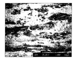
- FIG. 4 is an SEM image (magnification is 400 times) of the surface of the coated arc welding rod according to the present embodiment.
- the scale bar at the lower right indicates 10 ⁇ m.
- the white part is a coating layer containing a Ca compound
- the black part is the surface of the core wire.
- welding rod a coated arc welding rod (hereinafter sometimes simply referred to as “welding rod”) according to the present invention will be described in detail with reference to the drawings as appropriate.
- the numerical values before and after “ ⁇ ” include these numerical values. Numeric values with words such as “less than”, “smaller”, “greater than”, “greater than” are not included. In addition, a numerical value with a word such as “above” or “below” is included in the numerical value. Furthermore, “mass%” and “wt%” are synonymous.
- the welding rod 1 As shown in FIG. 1, the welding rod 1 according to this embodiment has a predetermined lengthwise direction in which a part of a core wire (steel core wire) 2 containing Fe (specifically, used as a filler metal). Are covered with the coating agent 3).
- the welding rod 1 shown in FIG. 1 is shown with a part cut away to explain the internal structure.
- Any coating material 3 can be used as long as it is used as a so-called flux in the coating arc welding. Examples of the coating 3 include TiO 2 , SiO 2 , Al 2 O 3 , CaCO 3 , MgCO 3 , BaCO 3 and the like.
- the coating agent 3 can be used alone by selecting one of the components described above, or can be used in combination of two or more.
- the core 2 can be a rod-shaped member having a circular cross section perpendicular to the longitudinal direction, but is not limited to this, and any shape that can be adopted as a welding rod is used. There may be.
- the welding rod 1 in which the core wire 2 is coated with the coating agent 3 has diameters of 1.6 mm ⁇ , 2.0 mm ⁇ , 2.5 mm ⁇ , 2 as defined in JIS Z 3200: 2005. .6 mm ⁇ (both include a tolerance of diameter ⁇ 0.06 mm ⁇ ), and the length in these cases can be 200 to 350 mm (including a tolerance of length ⁇ 5 mm).
- the diameter of the welding rod 1 is 3.2 mm ⁇ , 4.0 mm ⁇ , 4.5 mm ⁇ , 5.0 mm ⁇ , 5.5 mm ⁇ , 6.0 mm ⁇ , 6.4 mm ⁇ , 7.0 mm ⁇ (both diameter tolerance ⁇ 0.10 mm ⁇ ) And 8.0 mm ⁇ (including a diameter tolerance of ⁇ 0.1 mm ⁇ ), and the length in these cases should be 275 to 450 mm (including a length tolerance of ⁇ 5 mm). it can.
- the welding rod 1 which concerns on this embodiment is coat
- the grip portion 5 is a portion that is gripped by the welding holder 4 during welding.
- the welding rod 1 according to the present embodiment is such that the grip portion 5 is not covered with the coating agent 3 and the core wire 2 covered with the coating layer 6 is exposed. Yes.
- the grip part 5 is gripped by the welding holder 4 and used after the coating layer 6 covering the grip part 5 is peeled off by applying pressure or rubbing.
- the Ca compound contained in the coating layer 6 include calcium hydroxide and calcium oxide.
- the welding holder 4 is connected to a welding power source 8 by a cable 7.
- the welding power source 8 is connected to a base material (material to be welded) 10 to be welded by a cable 9. Any welding power source 8 can be used as long as the arc can be stably maintained.
- the current generated by the welding power source 8 may be direct current or alternating current.
- the welding rod 1 (electrode) side may be positive or negative.
- the voltage value and current value applied to the welding rod 1 may be appropriately set in consideration of the thickness of the base material 10 and the like.
- the cables 7 and 9, the welding power source 8, etc. commercially available ones can be used.
- the area ratio of the coating layer 6 to the grip portion 5 is 20% or more, the thickness of the coating layer 6 is 0.5 to 15 ⁇ m, and the surface roughness Ra of the coating layer 6 is. Is 1.0 ⁇ m or less.
- the arc stability of a welding rod is affected by the chemical composition of the core wire.
- this inventor examined, even if it was the welding rod manufactured using the core wire which has the same chemical component, it turned out that there is a difference in arc stability.
- the properties of the coating layer covering the surface of the core wires influence the arc stability.
- the arc stability can be greatly improved particularly when the grip portion 5 of the core wire 2 is covered with the coating layer 6 containing a Ca compound. Since the coating layer 6 containing the Ca compound is fixed to the surface of the core wire 2 with an appropriate fixing force, it is difficult to peel off without external pressure.
- the coating layer 6 at the portion in contact with the surface peels off, and the electrical conductivity can be secured.
- the coating layer 6 containing a Ca compound plays a role of preventing an oxide coating from being formed on the grip portion 5 of the core wire 2. For this reason, it can be said that the coating layer 6 is suitable for protecting the grip portion 5 of the core wire 2.
- the area ratio of the coating layer 6 that is, the ratio of the area where the coating layer 6 occupies the unit area of the grip portion 5 is 20% or more. Stability is ensured.
- the area ratio of the coating layer 6 is less than 20%, the formation of an oxide coating on the grip portion 5 of the core wire 2 cannot be prevented, and the arc stability is lowered.
- the area ratio of the coating layer 6 is preferably 40% or more, more preferably 50% or more, and further preferably 70% or more. Further, the area ratio of the coating layer 6 can be set to 100%, that is, the entire grip portion 5 can be completely covered with the coating layer 6.
- the area ratio of the coating layer 6 can be measured as follows. That is, using a WD / ED combine electron probe microanalyzer (EPMA) JXA-8200 manufactured by JEOL Ltd., an acceleration voltage of 15 kV, an irradiation current of 5 ⁇ 10 ⁇ 10 A, a grip portion 5 of the core wire 2 (Magnification is 400 times, visual field is 3 places). Then, the image analysis software JTrim is used to binarize 1280 ⁇ 950 pixels (the number of pixels 1216000) for one field of view, and the monochrome ratio is calculated. For binarization, the boundary threshold may be 128 (default setting). The area ratio of the coating layer 6 can be obtained by performing this for three visual fields and calculating the average value of the white ratio from the measurement result.
- EPMA WD / ED combine electron probe microanalyzer
- the thickness of the coating layer 6 is preferably 0.5 to 15 ⁇ m. If it does in this way, the film layer 6 is hard to peel until the time of welding, and it can be set as the aspect which this peels when the grip part 5 is gripped with the welding holder 4 at the time of welding, and a pressure is applied. On the other hand, if the thickness of the coating layer 6 exceeds 15 ⁇ m, peeling during welding becomes difficult. From the viewpoint of further improving the arc stability, the thickness of the coating layer 6 is more preferably 12 ⁇ m or less.
- the thickness of the coating layer 6 is less than 0.5 ⁇ m, the coating layer 6 is easily peeled off, so that the coating layer 6 may be peeled off from the grip portion 5 due to an impact during transportation. Furthermore, when the thickness of the coating layer 6 is less than 0.5 ⁇ m, the effect of preventing the oxide coating from being formed on the grip portion 5 of the core wire 2 becomes insufficient. From the viewpoint of obtaining this effect more sufficiently, the thickness of the coating layer 6 is more preferably 0.7 ⁇ m or more, and further preferably 1 ⁇ m or more.
- the thickness of the coating layer 6 is embedded in the resin so that the cross section perpendicular to the longitudinal direction of the core wire 2 becomes the observation surface, and the cross section of the core wire 2 is observed with a scanning electron microscope (SEM) ( Magnification 1000 times, backscattered electron (BSE) image). And the thickness of the coating layer 6 can be calculated
- SEM scanning electron microscope
- BSE backscattered electron
- the difficulty of peeling of the coating layer 6 varies depending on the surface roughness.
- the surface roughness (arithmetic mean roughness) Ra of the coating layer 6 is 1.0 ⁇ m or less, the coating layer 6 can be easily peeled by holding the grip portion 5 with the welding holder 4 and applying pressure during welding. .
- the surface roughness Ra of the coating layer 6 exceeds 1.0 ⁇ m, peeling during welding becomes difficult.
- surface roughness Ra of the coating layer 6 is so preferable that it is low, and although there is no prescription
- the surface roughness Ra of the coating layer 6 can be measured by using an apparatus according to JIS B 0601: 2001.
- the coating layer 6 has a Ca amount of 15 to 40% by mass and a C amount of 5 measured by energy dispersive X-ray spectroscopy (EDX). -25% by mass, O content is 30-70% by mass, and K content is 1-8% by mass.
- EDX energy dispersive X-ray spectroscopy
- Analysis by energy dispersive X-ray spectroscopy can be performed as follows. For example, using a WD / ED combine EPMA JXA-8200 manufactured by JEOL Ltd., EDX measurement is performed by selecting three 10 ⁇ m ⁇ 10 ⁇ m rectangular regions in the grip portion 5 for a field of view of 400 times magnification.
- the quantitative analysis of EDX can be performed by the pure standard method. The concentration (content) of each element is calculated from the intensity ratio between the standard sample and the actual sample. By performing this at the three locations and calculating the average value, the contents of Ca, C, O and K in the coating layer 6 by EDX can be determined.
- the welding rod 1 which concerns on this embodiment can be manufactured with the general installation and conditions which manufacture a welding rod.
- the welding rod 1 according to the present embodiment can be manufactured as follows, for example. First, wire bars and billets containing Fe are manufactured using general equipment and conditions. Subsequently, this is extruded and drawn, and the core wire 2 is manufactured.
- the lubricant which a calcium hydroxide is a main component (70 mass% or more) at the time of wire drawing is mentioned.
- the application amount of the lubricant can be 0.5 to 1.0 mg / cm 2 .
- the drawing speed can be 300 to 770 m / min.
- the temperature of the core wire 2 at the time of wire drawing can be 100 to 120 ° C. These conditions at the time of wire drawing are examples, and are not limited to these.
- the area ratio, thickness, and surface roughness Ra of the coating layer 6 are adjusted to the above-described ranges. These adjustments can be performed, for example, by using a mechanical descaler that removes the scale.
- the welding rod 1 which concerns on this embodiment can be manufactured by coat
- Wire bars having the components shown in Table 1 were produced using general equipment and conditions. Subsequently, the wire bar was drawn using the lubricants having the components shown in Table 2, and a core wire having a diameter of 3.2 mm ⁇ and a length of 350 mm was manufactured. And the coating layer containing a Ca compound was processed by changing the conditions in various ways using a mechanical scaler. A coated arc welding rod coated with a coating layer having an area ratio (%), thickness ( ⁇ m), and surface roughness Ra ( ⁇ m) shown in 1 to 20 was produced. The area ratio, thickness, and surface roughness of the coating layer containing the Ca compound were measured as follows.
- the area ratio of the coating layer containing the Ca compound to the grip portion is WD / ED combine EPMA JXA-8200 manufactured by JEOL Ltd., acceleration voltage 15 kV, irradiation current 5 ⁇ 10 ⁇ 10 In A, the grip portion of the core wire was analyzed (magnification 400 times, field of view 3 places). Then, 1280 ⁇ 950 pixels (pixel number: 1216000) were binarized using the image analysis software JTrim for one field of view, and the monochrome ratio was calculated. For binarization, the boundary threshold was set to 128. This was performed for three visual fields, and the average value of the white ratio was calculated from the measurement results, thereby obtaining the area ratio of the coating layer containing the Ca compound.
- Thickness of the coating layer The thickness of the coating layer containing the Ca compound is embedded in the resin so that the cross section perpendicular to the longitudinal direction of the core wire becomes the observation surface, and the cross section of the core wire is observed with an SEM (magnification 1000 times) , BSE image). And the thickness of the coating layer containing Ca compound was calculated
- Arc stability was evaluated by observing the voltage waveform and counting the number of sudden voltage drops that occurred per 30 seconds.
- the sudden voltage drop means that the voltage drops by 5 V or more with respect to the average voltage.
- a thick solid line indicated by ⁇ is an example of a voltage waveform in which no sudden voltage drop occurs
- a thin solid line indicated by x is an example of a voltage waveform in which a sudden voltage drop occurs.
- FIG. 3 in the example of the thin solid line indicated by x, it can be seen that a rapid voltage drop occurs at a location of about 14 seconds and a location of about 22 seconds.
- the voltage data was measured using NR2000 and NR2010 manufactured by Keyence Corporation.
- the data collection software is WAVE SHOT! 2000 (version 1.08, default setting) was used.
- Arc stability was evaluated as follows. A: The number of sudden voltage drops occurring per 30 seconds exceeds 0.5 and less than 1 time AA: The number of sudden voltage drops generated per 30 seconds exceeds 0 times and less than 0.5 times AAA: The number of sudden voltage drops that occur every 30 seconds is 0 (the number of sudden voltage drops is 3 after welding 3 times) B: The number of sudden voltage drops occurring per 30 seconds exceeds one. Note that the number of voltage drops was calculated by averaging three samples each of which was welded. The evaluation results of arc stability are shown in Table 3.
- FIG. 1 shows an SEM image (magnification is 400 times) of the surface of the coated arc welding rod according to No. 1;
- Table 3 shows the evaluation results of the welding rods according to 17-20. Specifically, no. The welding rod according to No. 17 was inferior in arc stability because the thickness of the coating layer containing the Ca compound was too thin. No. Since the area ratio of the coating layer containing a Ca compound was too small, the welding rod according to No. 18 had poor arc stability. No. Since the surface roughness of the coating layer containing a Ca compound was too rough, the welding rod according to 19 had poor arc stability. No. The welding rod according to No. 20 was inferior in arc stability because the thickness of the coating layer containing the Ca compound was too thick.
Landscapes
- Engineering & Computer Science (AREA)
- Mechanical Engineering (AREA)
- Physics & Mathematics (AREA)
- Plasma & Fusion (AREA)
- Nonmetallic Welding Materials (AREA)
Abstract
本発明はアーク安定性に優れた被覆アーク溶接棒を提供することを目的とする。本発明は、Feを含む心線の一部が被覆剤で被覆されている被覆アーク溶接棒であり、溶接ホルダーで把持される前記心線のグリップ部がCa化合物を含む被膜層で被覆されており、前記被膜層の面積率が前記グリップ部に対して20%以上、前記被膜層の厚さが0.5~15μm、かつ前記被膜層の表面粗さRaが1.0μm以下である被覆アーク溶接棒に関する。
Description
本発明は、被覆アーク溶接棒に関する。
被覆アーク溶接は、金属の棒(心線)に被覆剤と呼ばれるフラックスや保護材などを設けた被覆アーク溶接棒(単に、「溶接棒」や「手棒」などと呼称されることもある)を電極とし、母材との間にアークを発生させ、アーク熱で溶接棒と母材を溶融させて溶接を行う。被覆アーク溶接は、シールドガスを必要とせず、風が強い屋外などでも溶接することができ、各種製造工場、ビル、船舶、車両などで広く用いられている。
被覆アーク溶接棒には、アークを安定的に維持し、連続した溶接ビードを形成し、かつ溶接ビードにブローホールなどの欠陥が生じ難いことが求められている。これらの観点から、被覆アーク溶接棒について、例えば、特許文献1~3に記載の発明が提案されている。なお、アークを安定的に維持できることをアーク安定性が良いなどといい、アークを安定的に維持できないことをアーク安定性が悪いなどという。
特許文献1には、被覆剤中の硅砂の平均粒度と含有量を所定の範囲に制限すると共に、ルチール、炭酸石灰、蛍石、珪灰石、フェロマンガン、フェロシリコンの含有量をそれぞれ所定の範囲とした低水素系被覆アーク溶接棒が記載されている。
特許文献2には、C、Mn、Oの含有量をそれぞれ所定の範囲とし、Si、P、S、Cu、Nの含有量をそれぞれ所定値以下とした被覆アーク溶接棒が記載されている。
特許文献3には、心材素地に付着しているスケール結晶の結晶歪率を所定の範囲とした被覆アーク溶接棒が記載されている。
特許文献2には、C、Mn、Oの含有量をそれぞれ所定の範囲とし、Si、P、S、Cu、Nの含有量をそれぞれ所定値以下とした被覆アーク溶接棒が記載されている。
特許文献3には、心材素地に付着しているスケール結晶の結晶歪率を所定の範囲とした被覆アーク溶接棒が記載されている。
特許文献1~3に記載されている発明は、それぞれに提案されている内容でアーク安定性を向上させているが、アーク安定性を向上させることに関して改善の余地があった。本発明は前記状況に鑑みてなされたものであり、アーク安定性に優れた被覆アーク溶接棒を提供することを課題とする。
前記課題を解決した本発明に係る被覆アーク溶接棒は、Feを含む心線の一部が被覆剤で被覆されている被覆アーク溶接棒であり、溶接ホルダーで把持される前記心線のグリップ部がCa化合物を含む被膜層で被覆されており、前記被膜層の面積率が20%以上、前記被膜層の厚さが0.5~15μm、かつ前記被膜層の表面粗さRaが1.0μm以下であることを特徴としている。
従来の心線のグリップ部はフラックスなどの被覆剤で被覆されていないので、製造後から溶接で使用されるまでの間に表面が酸化し、FeOやFe2O3などを含む酸化被膜が形成される。心線のグリップ部に酸化被膜が形成されるとアークが不安定となる。
しかしながら、本発明に係る被覆アーク溶接棒は、Ca化合物を含む被膜層で心線のグリップ部を被覆しているため、心線に含まれるFeの酸化を防止できる。そのため、本発明に係る被覆アーク溶接棒における心線のグリップ部には酸化被膜が形成され難く、アークの安定性が向上する。
本発明に係る被覆アーク溶接棒では、Ca化合物を含む被膜層の面積率を所定値以上としているので、アーク安定性がより確実に向上する。また、本発明に係る被覆アーク溶接棒は、被膜層の厚さを所定の範囲とすると共に、被膜層の表面粗さRaを所定値以下としている。そのため、本発明に係る被覆アーク溶接棒は、溶接で使用されるまでCa化合物を含む被膜層が剥離し難いにも拘らず、溶接時に溶接ホルダーで把持して圧力を加えるだけで容易に当該被膜層が剥離し、安定したアークを発生させることができる。
しかしながら、本発明に係る被覆アーク溶接棒は、Ca化合物を含む被膜層で心線のグリップ部を被覆しているため、心線に含まれるFeの酸化を防止できる。そのため、本発明に係る被覆アーク溶接棒における心線のグリップ部には酸化被膜が形成され難く、アークの安定性が向上する。
本発明に係る被覆アーク溶接棒では、Ca化合物を含む被膜層の面積率を所定値以上としているので、アーク安定性がより確実に向上する。また、本発明に係る被覆アーク溶接棒は、被膜層の厚さを所定の範囲とすると共に、被膜層の表面粗さRaを所定値以下としている。そのため、本発明に係る被覆アーク溶接棒は、溶接で使用されるまでCa化合物を含む被膜層が剥離し難いにも拘らず、溶接時に溶接ホルダーで把持して圧力を加えるだけで容易に当該被膜層が剥離し、安定したアークを発生させることができる。
本発明に係る被覆アーク溶接棒は、エネルギー分散型X線分光法で測定した前記被膜層のCa量が15~40質量%、C量が5~25質量%、O量が30~70質量%、かつK量が1~8質量%であるのが好ましい。
このような構成としているので、本発明に係る被覆アーク溶接棒は、Caを含む被膜層の固着性と剥離性が良好になると共に、心線のグリップ部に酸化被膜の形成を防止する効果が向上するため、アーク安定性がより向上する。
このような構成としているので、本発明に係る被覆アーク溶接棒は、Caを含む被膜層の固着性と剥離性が良好になると共に、心線のグリップ部に酸化被膜の形成を防止する効果が向上するため、アーク安定性がより向上する。
本発明に係る被覆アーク溶接棒は、Ca化合物を含む被膜層で心線のグリップ部を被覆し、且つ当該被膜層の面積率、厚さ、及び表面粗さRaをそれぞれ特定しているので、アーク安定性に優れている。
以下、適宜図面を参照して本発明に係る被覆アーク溶接棒(以下、単に「溶接棒」ということがある)の一実施形態について詳細に説明する。なお、本明細書において、「~」で示されている前後の数値は、これらの数値を含むものとする。数値に「未満」、「より小さい」、「超える」、「より大きい」などの文言を付した数値は、当該数値を含まないものとする。また、数値に「以上」、「以下」などの文言を付した数値は、当該数値を含むものとする。さらに、“質量%”と“重量%”とは同義である。
(溶接棒)
図1に示すように、本実施形態に係る溶接棒1は、Feを含む心線(鋼心線)2の一部が(具体的には溶加材として使用される、長さ方向の所定の部分が)被覆剤3で被覆されている。なお、図1に示す溶接棒1はその一部を切欠いて図示し、内部構造を説明している。
被覆剤3は、被覆アーク溶接において、いわゆるフラックスとして使用されるものであれば任意のものを用いることができる。被覆剤3としては、例えば、TiO2、SiO2、Al2O3、CaCO3、MgCO3、BaCO3などを挙げることができる。被覆剤3は、前記した成分のうちから1種類を選択して単独で用いることができるし、2種類以上を選択し、組み合わせて用いることもできる。
図1に示すように、本実施形態に係る溶接棒1は、Feを含む心線(鋼心線)2の一部が(具体的には溶加材として使用される、長さ方向の所定の部分が)被覆剤3で被覆されている。なお、図1に示す溶接棒1はその一部を切欠いて図示し、内部構造を説明している。
被覆剤3は、被覆アーク溶接において、いわゆるフラックスとして使用されるものであれば任意のものを用いることができる。被覆剤3としては、例えば、TiO2、SiO2、Al2O3、CaCO3、MgCO3、BaCO3などを挙げることができる。被覆剤3は、前記した成分のうちから1種類を選択して単独で用いることができるし、2種類以上を選択し、組み合わせて用いることもできる。
心線2は、例えば、長手方向に対する垂直断面が円形である棒状の部材とすることができるが、これに限定されるものではなく、溶接棒として採用可能な形状であればどのような形状であってもよい。
心線2に被覆剤3が被覆されてなる溶接棒1は、具体的には、JIS Z 3200:2005に規定されているように、直径が1.6mmφ、2.0mmφ、2.5mmφ、2.6mmφ(いずれも径の許容差±0.06mmφを含む)とすることができ、これらの場合の長さは200~350mm(長さの許容差±5mmを含む)とすることができる。また、溶接棒1の直径は3.2mmφ、4.0mmφ、4.5mmφ、5.0mmφ、5.5mmφ、6.0mmφ、6.4mmφ、7.0mmφ(いずれも直径の許容差±0.10mmφを含む)、8.0mmφ(直径の許容差±0.1mmφを含む)とすることができ、これらの場合の長さは275~450mm(長さの許容差±5mmを含む)とすることができる。
そして、本実施形態に係る溶接棒1は、図2に示すように、溶接ホルダー4で把持される心線2のグリップ部5がCa化合物を含む被膜層6で被覆されている。なお、グリップ部5は、溶接時に溶接ホルダー4で把持される部分である。
また、図1および図2に示すように、本実施形態に係る溶接棒1は、グリップ部5が被覆剤3で被覆されておらず、被膜層6で被覆された心線2が露出している。溶接時には、溶接ホルダー4でグリップ部5を把持し、圧力を加えたり、擦ったりしてグリップ部5を被覆する被膜層6を剥離してから使用する。被膜層6に含まれるCa化合物としては、例えば、水酸化カルシウムや酸化カルシウムなどが挙げられる。
また、図1および図2に示すように、本実施形態に係る溶接棒1は、グリップ部5が被覆剤3で被覆されておらず、被膜層6で被覆された心線2が露出している。溶接時には、溶接ホルダー4でグリップ部5を把持し、圧力を加えたり、擦ったりしてグリップ部5を被覆する被膜層6を剥離してから使用する。被膜層6に含まれるCa化合物としては、例えば、水酸化カルシウムや酸化カルシウムなどが挙げられる。
ここで、溶接ホルダー4は、ケーブル7で溶接用電源8と接続されている。また、溶接用電源8は、ケーブル9で溶接が行われる母材(被溶接材)10と接続されている。溶接用電源8は、アークを安定的に維持できるものであれば任意のものを使用できる。溶接用電源8で発生させる電流は直流でもよいし、交流でもよい。直流で溶接を行う場合、溶接棒1(電極)側をプラスとしてもよいし、マイナスとしてもよい。溶接棒1に適用される電圧値および電流値は、母材10の厚さなどを勘案して適宜設定すればよい。溶接ホルダー4、ケーブル7,9、溶接用電源8などは市販されているものを用いることができる。
(被膜層の面積率、厚さ、表面粗さ)
そして、本実施形態に係る溶接棒1においては、被膜層6のグリップ部5に対する面積率を20%以上、被膜層6の厚さを0.5~15μm、かつ被膜層6の表面粗さRaを1.0μm以下としている。
そして、本実施形態に係る溶接棒1においては、被膜層6のグリップ部5に対する面積率を20%以上、被膜層6の厚さを0.5~15μm、かつ被膜層6の表面粗さRaを1.0μm以下としている。
一般的に、溶接棒のアーク安定性は、心線の化学成分の影響を受ける。本発明者が検討したところ、同じ化学成分を有する心線を用いて製造した溶接棒であっても、アーク安定性に差異があることが分かった。そして、本発明者が種々の心線を用いて研究した結果、心線の表面を被覆する被膜層の性状がアーク安定性に影響していることが分かった。
本発明者の検討では、特に、Ca化合物を含む被膜層6で心線2のグリップ部5を被覆すると、アーク安定性を大きく向上できることが分かった。Ca化合物を含む被膜層6は、心線2の表面に適度の固着力で固着しているため、外部圧力なしでは剥離し難いが、溶接時に溶接ホルダー4で把持すると、その圧力で溶接ホルダー4と接する箇所の被膜層6が剥離し、通電性を確保できる。また、Ca化合物を含む被膜層6が、心線2のグリップ部5に酸化被膜が形成されるのを防止する役割を果たしていると考えられる。このような理由から、被膜層6は、心線2のグリップ部5を保護するのに好適であるといえる。
本発明者の検討では、特に、Ca化合物を含む被膜層6で心線2のグリップ部5を被覆すると、アーク安定性を大きく向上できることが分かった。Ca化合物を含む被膜層6は、心線2の表面に適度の固着力で固着しているため、外部圧力なしでは剥離し難いが、溶接時に溶接ホルダー4で把持すると、その圧力で溶接ホルダー4と接する箇所の被膜層6が剥離し、通電性を確保できる。また、Ca化合物を含む被膜層6が、心線2のグリップ部5に酸化被膜が形成されるのを防止する役割を果たしていると考えられる。このような理由から、被膜層6は、心線2のグリップ部5を保護するのに好適であるといえる。
本実施形態に係る溶接棒1においては、被膜層6の面積率、すなわち、グリップ部5の単位面積に占める被膜層6が形成されている面積の割合が20%以上であると、良好なアーク安定性が確実に得られる。他方、被膜層6の面積率が20%未満であると、心線2のグリップ部5に酸化被膜が形成されるのを防止できないため、アーク安定性が低下する。
アーク安定性をより向上させる観点から、被膜層6の面積率は40%以上とするのが好ましく、50%以上とするのがより好ましく、70%以上とするのがさらに好ましい。また、前記被膜層6の面積率を100%とすること、すなわち、グリップ部5全体を完全に被膜層6で被覆することもできる。
アーク安定性をより向上させる観点から、被膜層6の面積率は40%以上とするのが好ましく、50%以上とするのがより好ましく、70%以上とするのがさらに好ましい。また、前記被膜層6の面積率を100%とすること、すなわち、グリップ部5全体を完全に被膜層6で被覆することもできる。
なお、被膜層6の面積率は次のようにして測定することができる。つまり、日本電子株式会社製 WD/EDコンバイン 電子プローブマイクロアナライザ(Electron Probe Micro Analyzer;EPMA)JXA-8200を使用し、加速電圧15kV、照射電流5×10⁻¹⁰Aで心線2のグリップ部5を分析する(倍率は400倍、視野は3ヶ所)。
そして、1つの視野に対し、画像解析ソフトJTrimを用いて1280×950ピクセル(ピクセル数1216000)を二値化し、白黒比率を計算する。二値化については、境界のしきい値を128(デフォルト設定)とするとよい。これを3視野分行い、測定結果から白の比率の平均値を算出することで、被膜層6の面積率を求めることができる。
そして、1つの視野に対し、画像解析ソフトJTrimを用いて1280×950ピクセル(ピクセル数1216000)を二値化し、白黒比率を計算する。二値化については、境界のしきい値を128(デフォルト設定)とするとよい。これを3視野分行い、測定結果から白の比率の平均値を算出することで、被膜層6の面積率を求めることができる。
また、被膜層6は、厚さにより剥離の難易度が変わる。本実施形態の場合、被膜層6の厚さを0.5~15μmとするのが好ましい。このようにすると、溶接時までは被膜層6が剥離し難く、溶接時に溶接ホルダー4でグリップ部5を把持して圧力をかけたときにこれが剥離される態様とすることができる。他方、被膜層6の厚さが15μmを超えると、溶接時の剥離が難くなる。なお、アーク安定性をより向上させる観点から、前記被膜層6の厚さは12μm以下とするのがより好ましい。また、被膜層6の厚さが0.5μm未満であると、容易に剥離してしまうため、搬送時の衝撃などで被膜層6がグリップ部5から剥離することがある。さらに、被膜層6の厚さが0.5μm未満であると、心線2のグリップ部5に酸化被膜が形成されるのを防止する効果が不十分となる。この効果をより十分に得る観点から、被膜層6の厚さは、0.7μm以上がより好ましく、1μm以上がさらに好ましい。
なお、被膜層6の厚さは、心線2の長手方向に対する垂直断面が観察面となるように樹脂に埋め込み、心線2の断面を走査型電子顕微鏡(Scanning Electron Microscope;SEM)で観察(倍率1000倍、反射電子(BackScattered Electron;BSE)像)する。そして、被膜層6の厚さを3ヶ所測定し、平均厚さを算出することで、被膜層6の厚さを求めることができる。
さらに、被膜層6は、表面粗さによっても剥離の難易度が変わる。被膜層6の表面粗さ(算術平均粗さ)Raが1.0μm以下であると、溶接時に溶接ホルダー4でグリップ部5を把持し、圧力をかけることで、被膜層6を容易に剥離できる。他方、被膜層6の表面粗さRaが1.0μmを超えると、溶接時の剥離が難しくなる。なお、被膜層6の表面粗さRaは低いほど好ましく、下限に規定はないが、0.05μm程度が現実的な下限である。被膜層6の表面粗さRaは、JIS B 0601:2001に準じた装置を用いることにより測定することができる。
(溶接棒の好ましい態様)
本実施形態に係る溶接棒1の好ましい態様として、エネルギー分散型X線分光法(Energy Dispersive X-ray spectroscopy;EDX)で測定した被膜層6のCa量が15~40質量%、C量が5~25質量%、O量が30~70質量%、かつK量が1~8質量%であることが挙げられる。被膜層6がCa、C、OおよびKをそれぞれ前記した範囲で含有していると、被膜層6の固着性と剥離性が良好になると共に、心線2のグリップ部5に酸化被膜が形成されるのを防止する効果が向上するため、アーク安定性がより向上する。
本実施形態に係る溶接棒1の好ましい態様として、エネルギー分散型X線分光法(Energy Dispersive X-ray spectroscopy;EDX)で測定した被膜層6のCa量が15~40質量%、C量が5~25質量%、O量が30~70質量%、かつK量が1~8質量%であることが挙げられる。被膜層6がCa、C、OおよびKをそれぞれ前記した範囲で含有していると、被膜層6の固着性と剥離性が良好になると共に、心線2のグリップ部5に酸化被膜が形成されるのを防止する効果が向上するため、アーク安定性がより向上する。
エネルギー分散型X線分光法による分析は次のようにして行うことができる。例えば、日本電子株式会社製 WD/EDコンバイン EPMA JXA-8200を用い、倍率400倍の視野について、グリップ部5における10μm×10μmの矩形の領域を3ヶ所選択し、EDX測定を行う。EDXの定量分析は、ピュアスタンダード法で行うことができる。標準試料と実試料との強度比から各元素の濃度(含有量)を算出する。これを前記3ヶ所について行い、その平均値を算出することで、EDXによる被膜層6中のCa、C、OおよびKの含有量を求めることができる。
(製造方法)
本実施形態に係る溶接棒1は、溶接棒を製造する一般的な設備および条件で製造することができる。本実施形態に係る溶接棒1は、例えば、次のようにして製造することができる。
まず、一般的な設備および条件でFeを含むワイヤバーやビレットなどを製造する。次いで、これを押出加工して伸線し、心線2を製造する。
なお、製造方法の一実施形態として、伸線時に水酸化カルシウムが主成分(70質量%以上)である潤滑剤を使用することが挙げられる。潤滑剤の塗布量は0.5~1.0mg/cm2とすることができる。伸線速度は300~770m/minとすることができる。伸線時の心線2の温度は100~120℃とすることができる。これらの伸線時の条件は一例であり、これらに限定されない。
このようにして心線2のグリップ部5に被膜層6を被覆した後、被膜層6の面積率、厚さおよび表面粗さRaをそれぞれ前記した範囲に調整する。これらの調整は、例えば、スケールを除去するメカニカルディスケーラーを用いることによって行うことができる。
その後、溶加材となる部分を被覆剤3で被覆することで、本実施形態に係る溶接棒1を製造することができる。
本実施形態に係る溶接棒1は、溶接棒を製造する一般的な設備および条件で製造することができる。本実施形態に係る溶接棒1は、例えば、次のようにして製造することができる。
まず、一般的な設備および条件でFeを含むワイヤバーやビレットなどを製造する。次いで、これを押出加工して伸線し、心線2を製造する。
なお、製造方法の一実施形態として、伸線時に水酸化カルシウムが主成分(70質量%以上)である潤滑剤を使用することが挙げられる。潤滑剤の塗布量は0.5~1.0mg/cm2とすることができる。伸線速度は300~770m/minとすることができる。伸線時の心線2の温度は100~120℃とすることができる。これらの伸線時の条件は一例であり、これらに限定されない。
このようにして心線2のグリップ部5に被膜層6を被覆した後、被膜層6の面積率、厚さおよび表面粗さRaをそれぞれ前記した範囲に調整する。これらの調整は、例えば、スケールを除去するメカニカルディスケーラーを用いることによって行うことができる。
その後、溶加材となる部分を被覆剤3で被覆することで、本実施形態に係る溶接棒1を製造することができる。
次に、本発明の効果を奏する実施例とそうでない比較例とを参照して、本発明の内容について具体的に説明する。
一般的な設備および条件で表1に示す成分のワイヤバーを製造した。次いで、表2に示す成分の潤滑剤を使用してワイヤバーを伸線し、直径3.2mmφ、長さ350mmの心線を製造した。そして、メカニカルディスケーラーを用い、条件を種々変更してCa化合物を含む被膜層を処理し、後記する表3のNo.1~20に示す面積率(%)、厚さ(μm)、表面粗さRa(μm)の被膜層で被覆された被覆アーク溶接棒を製造した。Ca化合物を含む被膜層の面積率、厚さ、表面粗さはそれぞれ次のようにして測定した。
一般的な設備および条件で表1に示す成分のワイヤバーを製造した。次いで、表2に示す成分の潤滑剤を使用してワイヤバーを伸線し、直径3.2mmφ、長さ350mmの心線を製造した。そして、メカニカルディスケーラーを用い、条件を種々変更してCa化合物を含む被膜層を処理し、後記する表3のNo.1~20に示す面積率(%)、厚さ(μm)、表面粗さRa(μm)の被膜層で被覆された被覆アーク溶接棒を製造した。Ca化合物を含む被膜層の面積率、厚さ、表面粗さはそれぞれ次のようにして測定した。


(1)被膜層の面積率
Ca化合物を含む被膜層のグリップ部に対する面積率は、日本電子株式会社製 WD/EDコンバイン EPMA JXA-8200を使用し、加速電圧15kV、照射電流5×10⁻¹⁰Aで心線のグリップ部を分析した(倍率は400倍、視野は3ヶ所)。そして、1つの視野に対し、画像解析ソフトJTrimを用いて1280×950ピクセル(ピクセル数1216000)を二値化し、白黒比率を計算した。二値化については、境界のしきい値を128とした。これを3視野分行い、測定結果から白の比率の平均値を算出することで、Ca化合物を含む被膜層の面積率を求めた。
Ca化合物を含む被膜層のグリップ部に対する面積率は、日本電子株式会社製 WD/EDコンバイン EPMA JXA-8200を使用し、加速電圧15kV、照射電流5×10⁻¹⁰Aで心線のグリップ部を分析した(倍率は400倍、視野は3ヶ所)。そして、1つの視野に対し、画像解析ソフトJTrimを用いて1280×950ピクセル(ピクセル数1216000)を二値化し、白黒比率を計算した。二値化については、境界のしきい値を128とした。これを3視野分行い、測定結果から白の比率の平均値を算出することで、Ca化合物を含む被膜層の面積率を求めた。
(2)被膜層の厚さ
Ca化合物を含む被膜層の厚さは、心線の長手方向に対する垂直断面が観察面となるように樹脂に埋め込み、心線の断面をSEMで観察(倍率1000倍、BSE像)した。そして、被膜層の厚さを3ヶ所測定し、平均厚さを算出することで、Ca化合物を含む被膜層の厚さを求めた。
Ca化合物を含む被膜層の厚さは、心線の長手方向に対する垂直断面が観察面となるように樹脂に埋め込み、心線の断面をSEMで観察(倍率1000倍、BSE像)した。そして、被膜層の厚さを3ヶ所測定し、平均厚さを算出することで、Ca化合物を含む被膜層の厚さを求めた。
(3)被膜層の表面粗さ
Ca化合物を含む被膜層の表面粗さRaは、JIS B 0601:2001に準じた装置を用いて測定した。
Ca化合物を含む被膜層の表面粗さRaは、JIS B 0601:2001に準じた装置を用いて測定した。
(4)アーク安定性
製造したNo.1~20に係る溶接棒を用い、下記の溶接条件で被覆アーク溶接を行い、アーク安定性を評価した。
製造したNo.1~20に係る溶接棒を用い、下記の溶接条件で被覆アーク溶接を行い、アーク安定性を評価した。
〔溶接条件〕
・溶接姿勢 :下向ビードオンプレート
・被覆アーク溶接棒直径:4.0mmφ
・電流値 :160Amp.(狙い)
・電圧 :25V(狙い)
・母材の板厚 :12mm
・溶接姿勢 :下向ビードオンプレート
・被覆アーク溶接棒直径:4.0mmφ
・電流値 :160Amp.(狙い)
・電圧 :25V(狙い)
・母材の板厚 :12mm
〔アーク安定性の評価〕
アーク安定性は、電圧波形を観察し、30秒当たりに生じる急激な電圧降下の回数をカウントすることで評価した。なお、急激な電圧降下とは、平均電圧に対して5V以上電圧が降下することをいう。図3において、◎で示す太い実線が、急激な電圧降下が生じていない電圧波形、×で示す細い実線が、急激な電圧降下が生じている電圧波形の一例である。図3に示すように、×で示す細い実線の例では、約14秒の箇所と約22秒の箇所で急激な電圧降下が生じていることが分かる。なお、電圧データの測定は、キーエンス社製NR2000およびNR2010を用いて行った。データ収集ソフトは、WAVE SHOT!2000(version 1.08、デフォルト設定)を使用した。
アーク安定性は、電圧波形を観察し、30秒当たりに生じる急激な電圧降下の回数をカウントすることで評価した。なお、急激な電圧降下とは、平均電圧に対して5V以上電圧が降下することをいう。図3において、◎で示す太い実線が、急激な電圧降下が生じていない電圧波形、×で示す細い実線が、急激な電圧降下が生じている電圧波形の一例である。図3に示すように、×で示す細い実線の例では、約14秒の箇所と約22秒の箇所で急激な電圧降下が生じていることが分かる。なお、電圧データの測定は、キーエンス社製NR2000およびNR2010を用いて行った。データ収集ソフトは、WAVE SHOT!2000(version 1.08、デフォルト設定)を使用した。
アーク安定性は以下のように評価した。
A :30秒当たりに生じる急激な電圧降下の回数が0.5回を超え、1回以下
AA :30秒当たりに生じる急激な電圧降下の回数が0回を超え、0.5回以下
AAA:30秒当たりに生じる急激な電圧降下の回数が0回(3回溶接して3回とも急激な電圧降下の回数が0回)
B :30秒当たりに生じる急激な電圧降下の回数が1回を超える
なお、電圧降下の回数は、それぞれのサンプルについて、3回ずつ溶接を行い、その平均値で算出した。アーク安定性の評価結果を表3に示す。
A :30秒当たりに生じる急激な電圧降下の回数が0.5回を超え、1回以下
AA :30秒当たりに生じる急激な電圧降下の回数が0回を超え、0.5回以下
AAA:30秒当たりに生じる急激な電圧降下の回数が0回(3回溶接して3回とも急激な電圧降下の回数が0回)
B :30秒当たりに生じる急激な電圧降下の回数が1回を超える
なお、電圧降下の回数は、それぞれのサンプルについて、3回ずつ溶接を行い、その平均値で算出した。アーク安定性の評価結果を表3に示す。
(5)被膜層中の元素の分析
また、次のようにして被膜層中の元素を分析した。日本電子株式会社製 WD/EDコンバイン EPMA JXA-8200を用い、倍率400倍の視野について、グリップ部における10μm×10μmの矩形の領域を3ヶ所選択し、EDX測定を行った。EDXの定量分析は、ピュアスタンダード法で行った。標準試料と実試料との強度比から各元素の含有量を算出した。これを前記3ヶ所について行い、その平均値を算出することで、EDXによる被膜層中のCa、C、OおよびKの含有量(質量%)とした。なお、表3において、Ca量が15~40質量%、C量が5~25質量%、O量が30~70質量%、K量が1~8質量%の範囲に含まれるものを“○”で示し、前記範囲に含まれないものは“×”で示した。
また、次のようにして被膜層中の元素を分析した。日本電子株式会社製 WD/EDコンバイン EPMA JXA-8200を用い、倍率400倍の視野について、グリップ部における10μm×10μmの矩形の領域を3ヶ所選択し、EDX測定を行った。EDXの定量分析は、ピュアスタンダード法で行った。標準試料と実試料との強度比から各元素の含有量を算出した。これを前記3ヶ所について行い、その平均値を算出することで、EDXによる被膜層中のCa、C、OおよびKの含有量(質量%)とした。なお、表3において、Ca量が15~40質量%、C量が5~25質量%、O量が30~70質量%、K量が1~8質量%の範囲に含まれるものを“○”で示し、前記範囲に含まれないものは“×”で示した。
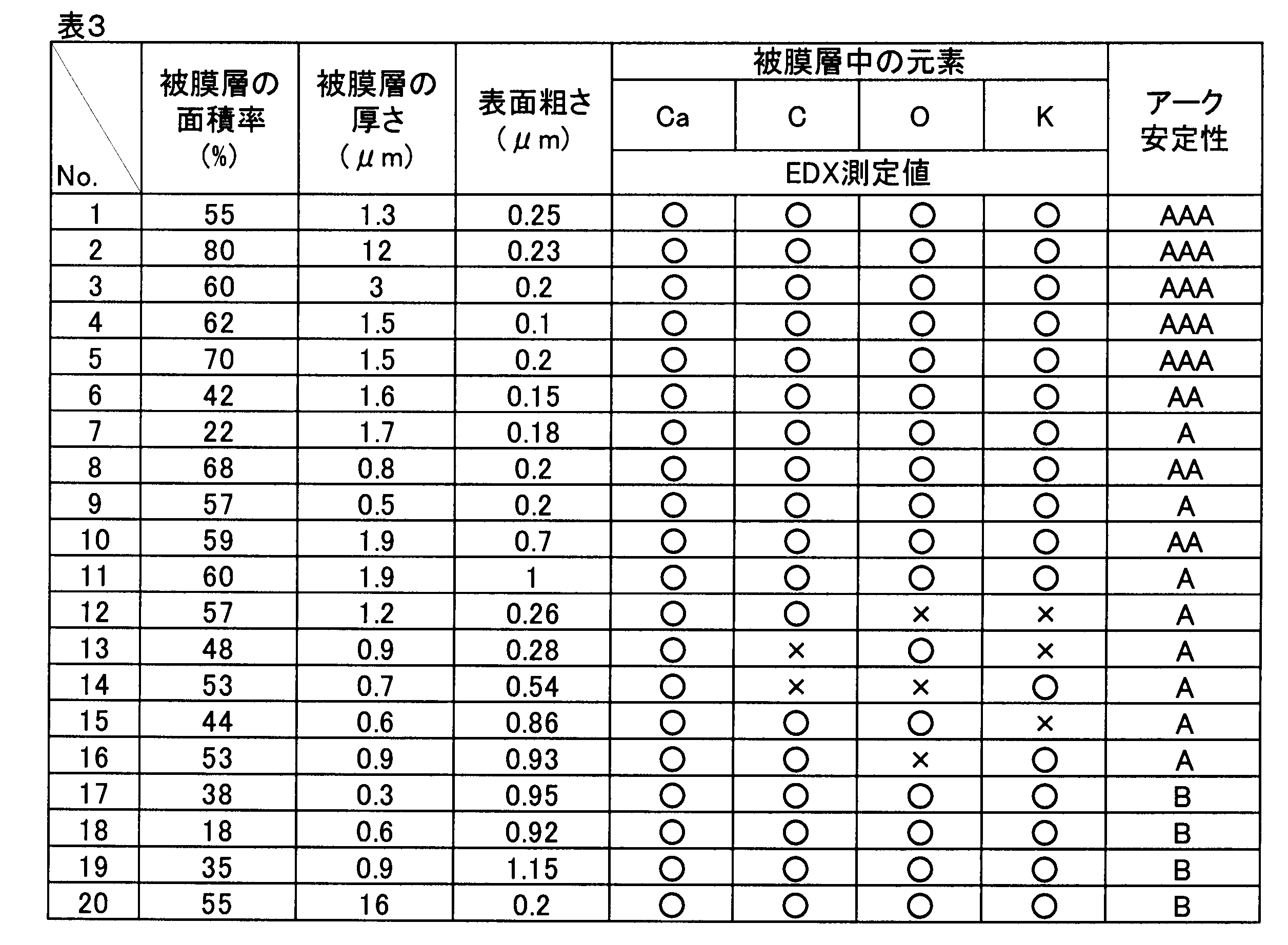
表3に示すように、本発明の実施形態に係るNo.1~16の溶接棒は、アーク安定性が優れていることを確認した。特に、Ca、C、OおよびKの含有量が所定の要件を満たしているNo.1~11に係る溶接棒は、アーク安定性がより優れている傾向にあった。なお、図4に、No.1に係る被覆アーク溶接棒の表面のSEM像(倍率は400倍)を示す。
これに対し、比較例としてNo.17~20に係る溶接棒の評価結果を表3に示す。
具体的には、No.17に係る溶接棒は、Ca化合物を含む被膜層の厚さが薄過ぎたので、アーク安定性が劣っていた。
No.18に係る溶接棒は、Ca化合物を含む被膜層の面積率が小さ過ぎたので、アーク安定性が劣っていた。
No.19に係る溶接棒は、Ca化合物を含む被膜層の表面粗さが粗過ぎたので、アーク安定性が劣っていた。
No.20に係る溶接棒は、Ca化合物を含む被膜層の厚さが厚過ぎたので、アーク安定性が劣っていた。
具体的には、No.17に係る溶接棒は、Ca化合物を含む被膜層の厚さが薄過ぎたので、アーク安定性が劣っていた。
No.18に係る溶接棒は、Ca化合物を含む被膜層の面積率が小さ過ぎたので、アーク安定性が劣っていた。
No.19に係る溶接棒は、Ca化合物を含む被膜層の表面粗さが粗過ぎたので、アーク安定性が劣っていた。
No.20に係る溶接棒は、Ca化合物を含む被膜層の厚さが厚過ぎたので、アーク安定性が劣っていた。
本発明を詳細に、また特定の実施態様を参照して説明したが、本発明の精神と範囲を逸脱することなく様々な変更や修正を加えることができることは当業者にとって明らかである。本出願は2016年7月28日出願の日本特許出願(特願2016-148388)に基づくものであり、その内容はここに参照として取り込まれる。
1 溶接棒(被覆アーク溶接棒)
2 心線
3 被覆剤
4 溶接ホルダー
5 グリップ部
6 被膜層
2 心線
3 被覆剤
4 溶接ホルダー
5 グリップ部
6 被膜層
Claims (2)
- Feを含む心線の一部が被覆剤で被覆されている被覆アーク溶接棒であり、
溶接ホルダーで把持される前記心線のグリップ部がCa化合物を含む被膜層で被覆されており、
前記被膜層の面積率が前記グリップ部に対して20%以上、
前記被膜層の厚さが0.5~15μm、かつ
前記被膜層の表面粗さRaが1.0μm以下
であることを特徴とする被覆アーク溶接棒。 - エネルギー分散型X線分光法で測定した前記被膜層のCa量が15~40質量%、C量が5~25質量%、O量が30~70質量%、かつK量が1~8質量%であることを特徴とする請求項1に記載の被覆アーク溶接棒。
Priority Applications (5)
| Application Number | Priority Date | Filing Date | Title |
|---|---|---|---|
| RU2019102028A RU2701917C1 (ru) | 2016-07-28 | 2017-07-05 | Электрод с покрытием |
| MYPI2019000423A MY189312A (en) | 2016-07-28 | 2017-07-05 | Covered electrode |
| SG11201900587WA SG11201900587WA (en) | 2016-07-28 | 2017-07-05 | Coated arc welding rod |
| CN201780045171.8A CN109475984B (zh) | 2016-07-28 | 2017-07-05 | 涂药焊条 |
| KR1020197002636A KR102124309B1 (ko) | 2016-07-28 | 2017-07-05 | 피복 아크 용접봉 |
Applications Claiming Priority (2)
| Application Number | Priority Date | Filing Date | Title |
|---|---|---|---|
| JP2016-148388 | 2016-07-28 | ||
| JP2016148388A JP6663321B2 (ja) | 2016-07-28 | 2016-07-28 | 被覆アーク溶接棒 |
Publications (1)
| Publication Number | Publication Date |
|---|---|
| WO2018020969A1 true WO2018020969A1 (ja) | 2018-02-01 |
Family
ID=61016574
Family Applications (1)
| Application Number | Title | Priority Date | Filing Date |
|---|---|---|---|
| PCT/JP2017/024573 Ceased WO2018020969A1 (ja) | 2016-07-28 | 2017-07-05 | 被覆アーク溶接棒 |
Country Status (7)
| Country | Link |
|---|---|
| JP (1) | JP6663321B2 (ja) |
| KR (1) | KR102124309B1 (ja) |
| CN (1) | CN109475984B (ja) |
| MY (1) | MY189312A (ja) |
| RU (1) | RU2701917C1 (ja) |
| SG (1) | SG11201900587WA (ja) |
| WO (1) | WO2018020969A1 (ja) |
Cited By (1)
| Publication number | Priority date | Publication date | Assignee | Title |
|---|---|---|---|---|
| RU2772409C1 (ru) * | 2021-07-16 | 2022-05-19 | Геннадий Геннадьевич Иванов | Электрододержатель для ручной электросварки с регулируемой длиной электрода |
Citations (2)
| Publication number | Priority date | Publication date | Assignee | Title |
|---|---|---|---|---|
| JPH10263879A (ja) * | 1997-03-21 | 1998-10-06 | Nippon Steel Corp | 高窒素オーステナイト系ステンレス鋼用被覆アーク溶接棒 |
| JP2002321091A (ja) * | 2001-04-23 | 2002-11-05 | Nippon Steel Weld Prod & Eng Co Ltd | 非低水素系被覆アーク溶接棒 |
Family Cites Families (11)
| Publication number | Priority date | Publication date | Assignee | Title |
|---|---|---|---|---|
| DE2621572C3 (de) * | 1976-05-14 | 1979-03-01 | C. Conradty Nuernberg Gmbh & Co Kg, 8505 Roethenbach | Kuppelbare Stabelektrode zum Lichtbogenschweißen oder -schneiden |
| SU967753A1 (ru) * | 1980-07-30 | 1982-10-23 | Ордена Ленина И Ордена Трудового Красного Знамени Институт Электросварки Им.Е.О.Патона | Состав электродного покрыти и способ изготовлени обмазочной массы дл покрыти сварочных электродов |
| JPS58209498A (ja) | 1982-05-06 | 1983-12-06 | Kawasaki Steel Corp | 被覆ア−ク溶接棒 |
| JPS62179895A (ja) | 1986-02-05 | 1987-08-07 | Kobe Steel Ltd | 被覆ア−ク溶接棒 |
| JPH05169296A (ja) | 1991-12-20 | 1993-07-09 | Nippon Steel Corp | 低水素系被覆アーク溶接棒 |
| RU2049636C1 (ru) * | 1992-11-11 | 1995-12-10 | Краснодарский филиал Всесоюзного научно-исследовательского института монтажных и специальных строительных работ | Состав электродного покрытия |
| JP2010110817A (ja) * | 2008-10-11 | 2010-05-20 | Kobe Steel Ltd | 低水素系被覆アーク溶接棒 |
| CN203265935U (zh) * | 2013-05-09 | 2013-11-06 | 常州市五星铝化厂 | 新型高效焊条 |
| CN103433639A (zh) * | 2013-08-23 | 2013-12-11 | 昆山市宏嘉焊锡制造有限公司 | 一种便于夹持的焊条 |
| US10279435B2 (en) * | 2014-06-11 | 2019-05-07 | Lincoln Global, Inc. | Stick electrode |
| CN104942465A (zh) * | 2015-06-15 | 2015-09-30 | 赵兰 | 碳钢焊条及其制造方法 |
-
2016
- 2016-07-28 JP JP2016148388A patent/JP6663321B2/ja active Active
-
2017
- 2017-07-05 KR KR1020197002636A patent/KR102124309B1/ko active Active
- 2017-07-05 CN CN201780045171.8A patent/CN109475984B/zh active Active
- 2017-07-05 MY MYPI2019000423A patent/MY189312A/en unknown
- 2017-07-05 WO PCT/JP2017/024573 patent/WO2018020969A1/ja not_active Ceased
- 2017-07-05 RU RU2019102028A patent/RU2701917C1/ru active
- 2017-07-05 SG SG11201900587WA patent/SG11201900587WA/en unknown
Patent Citations (2)
| Publication number | Priority date | Publication date | Assignee | Title |
|---|---|---|---|---|
| JPH10263879A (ja) * | 1997-03-21 | 1998-10-06 | Nippon Steel Corp | 高窒素オーステナイト系ステンレス鋼用被覆アーク溶接棒 |
| JP2002321091A (ja) * | 2001-04-23 | 2002-11-05 | Nippon Steel Weld Prod & Eng Co Ltd | 非低水素系被覆アーク溶接棒 |
Cited By (1)
| Publication number | Priority date | Publication date | Assignee | Title |
|---|---|---|---|---|
| RU2772409C1 (ru) * | 2021-07-16 | 2022-05-19 | Геннадий Геннадьевич Иванов | Электрододержатель для ручной электросварки с регулируемой длиной электрода |
Also Published As
| Publication number | Publication date |
|---|---|
| RU2701917C1 (ru) | 2019-10-02 |
| KR20190026790A (ko) | 2019-03-13 |
| CN109475984A (zh) | 2019-03-15 |
| CN109475984B (zh) | 2019-07-19 |
| KR102124309B1 (ko) | 2020-06-18 |
| MY189312A (en) | 2022-02-04 |
| JP2018015786A (ja) | 2018-02-01 |
| SG11201900587WA (en) | 2019-02-27 |
| JP6663321B2 (ja) | 2020-03-11 |
Similar Documents
| Publication | Publication Date | Title |
|---|---|---|
| EP2977139B1 (en) | Welding filler material for bonding different kind materials, and method for producing different kind material welded structure | |
| JP6452912B1 (ja) | めっき線棒材及びその製造方法、並びにこれを用いて形成されたケーブル、電線、コイル及びばね部材 | |
| JP2006019163A (ja) | アルミ導電線 | |
| JP2010157416A (ja) | アルミニウム合金線 | |
| US10597792B2 (en) | Electrically conductive material for connection component | |
| JP6663321B2 (ja) | 被覆アーク溶接棒 | |
| CN105283262B (zh) | 用于放电切割物体的电极丝 | |
| KR101181214B1 (ko) | 동도금된 가스 실드 아크 용접용 플럭스 코어드 와이어 및 이의 제조방법 | |
| Reisgen et al. | Influence of storage conditions on aluminum 4043A welding wires | |
| KR100626416B1 (ko) | 가스 실드 아크 용접용 도금 와이어 | |
| CN111542899A (zh) | 铝系线材、绞线导体、编织线以及线束 | |
| JP2007152398A (ja) | 銅被覆アルミニウム線の製造方法 | |
| JP2009148774A (ja) | ガスシールドアーク溶接用ルチール系フラックス入りワイヤ | |
| US6696170B2 (en) | Copper-free wire | |
| JP2672153B2 (ja) | 溶接用ワイヤ | |
| JP5863570B2 (ja) | ガスシールドアーク溶接用フラックス入りワイヤ | |
| WO2020189689A1 (ja) | アルミニウム基線材 | |
| JP2731505B2 (ja) | アーク溶接用ワイヤ | |
| JPH07100687A (ja) | アーク溶接用ワイヤ | |
| JP3780453B2 (ja) | 銅メッキなしアーク溶接用ソリッドワイヤ | |
| JPH0970685A (ja) | 溶接作業性の良いガスシールドアーク溶接用ワイヤおよびその製造方法 | |
| JPH09253880A (ja) | 溶接ワイヤ及びその製造方法 | |
| JP2006019165A (ja) | アルミ導電線 | |
| JP7323781B2 (ja) | 多電極サブマージアーク溶接方法 | |
| JP2006004757A (ja) | アルミ導電線 |
Legal Events
| Date | Code | Title | Description |
|---|---|---|---|
| 121 | Ep: the epo has been informed by wipo that ep was designated in this application |
Ref document number: 17833978 Country of ref document: EP Kind code of ref document: A1 |
|
| ENP | Entry into the national phase |
Ref document number: 20197002636 Country of ref document: KR Kind code of ref document: A |
|
| NENP | Non-entry into the national phase |
Ref country code: DE |
|
| 122 | Ep: pct application non-entry in european phase |
Ref document number: 17833978 Country of ref document: EP Kind code of ref document: A1 |