WO2018020960A1 - ガス発生器 - Google Patents
ガス発生器 Download PDFInfo
- Publication number
- WO2018020960A1 WO2018020960A1 PCT/JP2017/024358 JP2017024358W WO2018020960A1 WO 2018020960 A1 WO2018020960 A1 WO 2018020960A1 JP 2017024358 W JP2017024358 W JP 2017024358W WO 2018020960 A1 WO2018020960 A1 WO 2018020960A1
- Authority
- WO
- WIPO (PCT)
- Prior art keywords
- cup
- peripheral wall
- filter
- wall portion
- diffuser
- Prior art date
- Legal status (The legal status is an assumption and is not a legal conclusion. Google has not performed a legal analysis and makes no representation as to the accuracy of the status listed.)
- Ceased
Links
Images





Classifications
-
- B—PERFORMING OPERATIONS; TRANSPORTING
- B60—VEHICLES IN GENERAL
- B60R—VEHICLES, VEHICLE FITTINGS, OR VEHICLE PARTS, NOT OTHERWISE PROVIDED FOR
- B60R21/00—Arrangements or fittings on vehicles for protecting or preventing injuries to occupants or pedestrians in case of accidents or other traffic risks
- B60R21/02—Occupant safety arrangements or fittings, e.g. crash pads
- B60R21/16—Inflatable occupant restraints or confinements designed to inflate upon impact or impending impact, e.g. air bags
- B60R21/26—Inflatable occupant restraints or confinements designed to inflate upon impact or impending impact, e.g. air bags characterised by the inflation fluid source or means to control inflation fluid flow
- B60R21/264—Inflatable occupant restraints or confinements designed to inflate upon impact or impending impact, e.g. air bags characterised by the inflation fluid source or means to control inflation fluid flow using instantaneous generation of gas, e.g. pyrotechnic
- B60R21/2644—Inflatable occupant restraints or confinements designed to inflate upon impact or impending impact, e.g. air bags characterised by the inflation fluid source or means to control inflation fluid flow using instantaneous generation of gas, e.g. pyrotechnic using only solid reacting substances, e.g. pellets, powder
-
- B—PERFORMING OPERATIONS; TRANSPORTING
- B60—VEHICLES IN GENERAL
- B60R—VEHICLES, VEHICLE FITTINGS, OR VEHICLE PARTS, NOT OTHERWISE PROVIDED FOR
- B60R21/00—Arrangements or fittings on vehicles for protecting or preventing injuries to occupants or pedestrians in case of accidents or other traffic risks
- B60R21/02—Occupant safety arrangements or fittings, e.g. crash pads
- B60R21/16—Inflatable occupant restraints or confinements designed to inflate upon impact or impending impact, e.g. air bags
- B60R21/20—Arrangements for storing inflatable members in their non-use or deflated condition; Arrangement or mounting of air bag modules or components
- B60R21/217—Inflation fluid source retainers, e.g. reaction canisters; Connection of bags, covers, diffusers or inflation fluid sources therewith or together
- B60R21/2176—Inflation fluid source retainers, e.g. reaction canisters; Connection of bags, covers, diffusers or inflation fluid sources therewith or together the air bag components being completely enclosed in a soft or semi-rigid housing or cover
-
- B—PERFORMING OPERATIONS; TRANSPORTING
- B60—VEHICLES IN GENERAL
- B60R—VEHICLES, VEHICLE FITTINGS, OR VEHICLE PARTS, NOT OTHERWISE PROVIDED FOR
- B60R21/00—Arrangements or fittings on vehicles for protecting or preventing injuries to occupants or pedestrians in case of accidents or other traffic risks
- B60R21/02—Occupant safety arrangements or fittings, e.g. crash pads
- B60R21/16—Inflatable occupant restraints or confinements designed to inflate upon impact or impending impact, e.g. air bags
- B60R21/23—Inflatable members
- B60R21/231—Inflatable members characterised by their shape, construction or spatial configuration
- B60R21/2334—Expansion control features
- B60R21/2346—Soft diffusers
-
- B—PERFORMING OPERATIONS; TRANSPORTING
- B60—VEHICLES IN GENERAL
- B60R—VEHICLES, VEHICLE FITTINGS, OR VEHICLE PARTS, NOT OTHERWISE PROVIDED FOR
- B60R21/00—Arrangements or fittings on vehicles for protecting or preventing injuries to occupants or pedestrians in case of accidents or other traffic risks
- B60R21/02—Occupant safety arrangements or fittings, e.g. crash pads
- B60R21/16—Inflatable occupant restraints or confinements designed to inflate upon impact or impending impact, e.g. air bags
- B60R21/26—Inflatable occupant restraints or confinements designed to inflate upon impact or impending impact, e.g. air bags characterised by the inflation fluid source or means to control inflation fluid flow
- B60R21/261—Inflatable occupant restraints or confinements designed to inflate upon impact or impending impact, e.g. air bags characterised by the inflation fluid source or means to control inflation fluid flow with means other than bag structure to diffuse or guide inflation fluid
-
- B—PERFORMING OPERATIONS; TRANSPORTING
- B60—VEHICLES IN GENERAL
- B60R—VEHICLES, VEHICLE FITTINGS, OR VEHICLE PARTS, NOT OTHERWISE PROVIDED FOR
- B60R21/00—Arrangements or fittings on vehicles for protecting or preventing injuries to occupants or pedestrians in case of accidents or other traffic risks
- B60R21/02—Occupant safety arrangements or fittings, e.g. crash pads
- B60R21/16—Inflatable occupant restraints or confinements designed to inflate upon impact or impending impact, e.g. air bags
- B60R21/26—Inflatable occupant restraints or confinements designed to inflate upon impact or impending impact, e.g. air bags characterised by the inflation fluid source or means to control inflation fluid flow
- B60R21/261—Inflatable occupant restraints or confinements designed to inflate upon impact or impending impact, e.g. air bags characterised by the inflation fluid source or means to control inflation fluid flow with means other than bag structure to diffuse or guide inflation fluid
- B60R21/262—Elongated tubular diffusers, e.g. curtain-type
-
- B—PERFORMING OPERATIONS; TRANSPORTING
- B60—VEHICLES IN GENERAL
- B60R—VEHICLES, VEHICLE FITTINGS, OR VEHICLE PARTS, NOT OTHERWISE PROVIDED FOR
- B60R21/00—Arrangements or fittings on vehicles for protecting or preventing injuries to occupants or pedestrians in case of accidents or other traffic risks
- B60R21/02—Occupant safety arrangements or fittings, e.g. crash pads
- B60R21/16—Inflatable occupant restraints or confinements designed to inflate upon impact or impending impact, e.g. air bags
- B60R21/26—Inflatable occupant restraints or confinements designed to inflate upon impact or impending impact, e.g. air bags characterised by the inflation fluid source or means to control inflation fluid flow
- B60R21/264—Inflatable occupant restraints or confinements designed to inflate upon impact or impending impact, e.g. air bags characterised by the inflation fluid source or means to control inflation fluid flow using instantaneous generation of gas, e.g. pyrotechnic
-
- B—PERFORMING OPERATIONS; TRANSPORTING
- B60—VEHICLES IN GENERAL
- B60R—VEHICLES, VEHICLE FITTINGS, OR VEHICLE PARTS, NOT OTHERWISE PROVIDED FOR
- B60R21/00—Arrangements or fittings on vehicles for protecting or preventing injuries to occupants or pedestrians in case of accidents or other traffic risks
- B60R21/02—Occupant safety arrangements or fittings, e.g. crash pads
- B60R21/16—Inflatable occupant restraints or confinements designed to inflate upon impact or impending impact, e.g. air bags
- B60R21/26—Inflatable occupant restraints or confinements designed to inflate upon impact or impending impact, e.g. air bags characterised by the inflation fluid source or means to control inflation fluid flow
- B60R2021/26011—Inflatable occupant restraints or confinements designed to inflate upon impact or impending impact, e.g. air bags characterised by the inflation fluid source or means to control inflation fluid flow using a filter through which the inflation gas passes
-
- B—PERFORMING OPERATIONS; TRANSPORTING
- B60—VEHICLES IN GENERAL
- B60R—VEHICLES, VEHICLE FITTINGS, OR VEHICLE PARTS, NOT OTHERWISE PROVIDED FOR
- B60R21/00—Arrangements or fittings on vehicles for protecting or preventing injuries to occupants or pedestrians in case of accidents or other traffic risks
- B60R21/02—Occupant safety arrangements or fittings, e.g. crash pads
- B60R21/16—Inflatable occupant restraints or confinements designed to inflate upon impact or impending impact, e.g. air bags
- B60R21/26—Inflatable occupant restraints or confinements designed to inflate upon impact or impending impact, e.g. air bags characterised by the inflation fluid source or means to control inflation fluid flow
- B60R21/261—Inflatable occupant restraints or confinements designed to inflate upon impact or impending impact, e.g. air bags characterised by the inflation fluid source or means to control inflation fluid flow with means other than bag structure to diffuse or guide inflation fluid
- B60R2021/2612—Gas guiding means, e.g. ducts
-
- B—PERFORMING OPERATIONS; TRANSPORTING
- B60—VEHICLES IN GENERAL
- B60R—VEHICLES, VEHICLE FITTINGS, OR VEHICLE PARTS, NOT OTHERWISE PROVIDED FOR
- B60R21/00—Arrangements or fittings on vehicles for protecting or preventing injuries to occupants or pedestrians in case of accidents or other traffic risks
- B60R21/02—Occupant safety arrangements or fittings, e.g. crash pads
- B60R21/16—Inflatable occupant restraints or confinements designed to inflate upon impact or impending impact, e.g. air bags
- B60R21/26—Inflatable occupant restraints or confinements designed to inflate upon impact or impending impact, e.g. air bags characterised by the inflation fluid source or means to control inflation fluid flow
- B60R21/264—Inflatable occupant restraints or confinements designed to inflate upon impact or impending impact, e.g. air bags characterised by the inflation fluid source or means to control inflation fluid flow using instantaneous generation of gas, e.g. pyrotechnic
- B60R21/2644—Inflatable occupant restraints or confinements designed to inflate upon impact or impending impact, e.g. air bags characterised by the inflation fluid source or means to control inflation fluid flow using instantaneous generation of gas, e.g. pyrotechnic using only solid reacting substances, e.g. pellets, powder
- B60R2021/2648—Inflatable occupant restraints or confinements designed to inflate upon impact or impending impact, e.g. air bags characterised by the inflation fluid source or means to control inflation fluid flow using instantaneous generation of gas, e.g. pyrotechnic using only solid reacting substances, e.g. pellets, powder comprising a plurality of combustion chambers or sub-chambers
Definitions
- the present invention relates to a gas generator that can be used in an airbag device mounted on an automobile.
- BACKGROUND ART DE202005008938U discloses a hybrid type gas generator using a pressurized gas and a gas generating agent in combination as a gas source.
- a housing to which the gas generating agent 12 and the ignition device 10 are attached is disposed on one end side.
- a radial opening 28 is formed in the peripheral wall 30 and a housing in which the filter 24 is accommodated is disposed.
- the inlet port 16 on one end side of the bottle is closed by the inlet film 18, and the discharge opening 20 on the opposite end side is closed by the discharge opening film 22.
- the filter 24 is outside the bottle filled with the pressurized gas, and is arranged at a position adjacent to the discharge opening 20.
- the present invention has a cylindrical housing composed of a cylindrical housing body portion and a diffuser portion, An ignition device is provided on the first end side of the cylindrical housing body, and a second end side opposite to the first end is closed by a diffuser portion having a plurality of gas discharge ports. , There is a combustion chamber containing a gas generating agent in the internal space of the cylindrical housing body, The combustion chamber and the diffuser portion are partitioned by a cup-shaped member, The cup-shaped member has a bottom surface portion, a peripheral wall portion in which a plurality of communication holes are formed, and an opening portion, the bottom surface portion is positioned on the first end portion side, and the opening portion is a second end portion.
- a first gap that communicates the combustion chamber and the diffuser portion is formed between the peripheral wall portion and the inner wall surface of the cylindrical housing main body portion that faces the radially outer side.
- a filter is disposed in a space surrounded by the cup-shaped member and the diffuser part,
- the filter is a cup-shaped filter having a bottom surface portion, a peripheral wall portion and an opening,
- the bottom surface portion of the filter is in contact with the closed end surface of the diffuser portion, the end surface of the opening is opposed to the bottom surface portion of the cup-shaped member, and the peripheral wall portion includes the plurality of communication holes.
- FIG. 1 is a cross-sectional view of the gas generator of the present invention in the direction of the axis X.
- FIG. 2 is a partial cross-sectional view in the axis X direction of a gas generator according to another embodiment using a filter different from that in FIG.
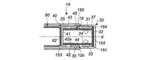
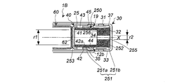
- FIG. 3 is a partial cross-sectional view in the axis X direction of another embodiment of the gas generator using a filter different from those in FIGS. 1 and 2.
- FIG. 4 is a partial cross-sectional view for explaining the positional relationship between the filter and the gas outlet in FIG.
- FIG. 5 is a partial cross-sectional view in the direction of the axis X of another embodiment of the gas generator using a filter different from that shown in FIGS.
- FIG. 1 is a cross-sectional view of the gas generator of the present invention in the direction of the axis X.
- FIG. 2 is a partial cross-sectional view in the axis X direction of a gas generator according to another embodiment using a filter
- FIG. 6 is a partial cross-sectional view in the direction of the axis X of another embodiment of the gas generator using a filter different from that shown in FIGS.
- FIG. 7 is a partial cross-sectional view for explaining the positional relationship between the filter and the gas outlet in FIG.
- FIG. 8 is a partial cross-sectional view in the axis X direction of another embodiment of the gas generator using a filter different from that in FIGS.
- FIG. 9 is a partial cross-sectional view in the direction of the axis X of another embodiment of the gas generator using a filter different from that in FIGS.
- the filter is not expanded and deformed radially outward by the pressure of the combustion gas, and a space between the filter and the gas discharge port can be secured. For this reason, the designed filter function is exhibited and the output of the gas generator is stabilized, so that the gas generator has high output reproducibility.
- the cylindrical housing used in the present invention is made of metal such as iron or stainless steel, and includes a cylindrical housing main body and a diffuser.
- the cylindrical housing main body portion and the diffuser portion may be joined by welding or may be integrally formed in advance.
- the ignition device can use an electric igniter used in a known gas generator, or a combination of an electric igniter and a transfer charge.
- an electric igniter used in a known gas generator, or a combination of an electric igniter and a transfer charge.
- the explosive charge a known gas generating agent or black explosive can be used.
- a plurality of gas discharge ports of the diffuser portion are formed on the peripheral wall portion of the cylindrical housing (diffuser portion), and are closed by a closing means such as a seal tape.
- gas generating agent filled in the combustion chamber those used in known gas generators can be used.
- the combustion chamber and the diffuser part are partitioned by a cup-shaped member.
- partitioned means that the combustion chamber space and the inner space of the diffuser portion are separated by a cup-shaped member, but a gas discharge path from the combustion chamber to the diffuser portion is secured.
- the gas discharge path from the combustion chamber to the diffuser section is a gas discharge path including the combustion chamber, the first gap, the plurality of communication holes, the cup-shaped filter, and the diffuser section.
- the cup-shaped member only needs to be arranged so that a first gap that communicates the combustion chamber and the diffuser portion is formed between the inner wall surface of the cylindrical housing main body portion.
- the cup-shaped member is fixed in the following form. can do.
- annular protrusion (annular step surface) protruding inward is formed between the cylindrical housing main body portion and the diffuser portion, and an opening end surface of the cup-shaped member is formed on the annular protrusion (annular step surface). Abutted form.
- an outer diameter of the turned-up portion and a cylindrical housing are used which has an enlarged-diameter portion in the opening and further has a turned-up portion from the enlarged diameter portion toward the bottom surface portion.
- turning part of the cup-shaped member was press-fitted with respect to the inner wall surface of a cylindrical housing by adjusting the internal diameter of.
- the outer diameter (d1) of the bottom surface and the outer diameter (d2) of the opening are d2> d1
- the peripheral wall from the bottom to the opening is an inclined surface, and further formed in the opening
- the outer diameter of the folded portion and the inner diameter of the cylindrical housing are adjusted, so that the folded portion of the cup-shaped member becomes a cylinder.
- the shape is press-fitted into the inner wall surface of the housing.
- the filter may be press-fitted into the cup-shaped member or the cup-shaped member so that the bottom surface is in contact with the closed end surface of the diffuser section and the end surface of the opening faces the bottom surface of the cup-shaped member.
- Protrusions are provided on the inner peripheral surface of the peripheral wall portion, and the opening side is brought into contact with the projections to prevent movement in the axial direction.
- the filter is supported from the radial direction by the peripheral wall portion coming into contact with the peripheral wall portion of the cup-shaped member including a plurality of communication holes from the inside. Since the filter is disposed with the second gap between the gas outlet and the gas, the filter can sufficiently exhibit the filter function because the gas can pass through the entire surface of the filter facing the second gap. .
- the combustion gas generated by the combustion of the gas generating agent in the combustion chamber passes through the peripheral wall near the opening side end face of the cup-shaped filter from the combustion chamber, the first gap, and the plurality of communication holes. Then enter the filter. Thereafter, after passing through the peripheral wall portion facing the second gap of the same cup-shaped filter, the seal tape is broken and discharged from the gas discharge port.
- the gas generator of the present invention that operates as described above can obtain the following effects (i) to (iii).
- the bottom surface of the filter is disposed so as to abut against the closed end surface of the diffuser portion. Therefore, even when a load due to combustion gas flowing from the inside to the outside of the filter is generated, The bottom surface portion of the faced filter and the peripheral wall portion on the bottom surface portion side are not easily deformed. For this reason, it is difficult for the second gap to be narrowed, and cooling and filtering can be performed on the entire surface of the peripheral wall portion facing the second gap of the filter. As a result, the designed filter function is exhibited and the output of the gas generator is stabilized, so that the gas generator has high output reproducibility.
- the effect (i) is a state in which the thickness of one end of the conventional cylindrical filter is partially increased, and the one end corresponds to the bottom surface.
- the filter is not limited to a filter whose bottom portion is completely closed, and the filter bottom portion is smaller than the diameter of the opening as long as it functions to prevent deformation when the gas generator is operated in the normal mode.
- a hole having a diameter may be formed.
- a preferred aspect of the gas generator of the present invention is a cup-shaped filter in which the filter has a bottom surface portion, a peripheral wall portion, an opening portion, and an annular portion protruding radially outward from the bottom surface portion,
- the bottom surface portion of the filter is in contact with the closed end surface of the diffuser portion
- the annular portion is in contact with the closed end surface of the diffuser portion and the peripheral wall portion
- the end surface of the opening is in contact with the bottom surface portion of the cup-shaped member.
- the peripheral wall portion is in contact with the peripheral wall portion of the cup-shaped member including the plurality of communication holes from the inside, and is disposed with a second gap between the gas discharge port and the peripheral wall portion.
- This aspect has an annular portion that protrudes radially outward from the bottom surface portion of the filter, and the annular portion is in contact with both the closed end face and the peripheral wall portion of the diffuser portion. Is substantially the same as the width of the second gap.
- the bottom surface portion facing the second gap and the peripheral wall portion on the bottom surface portion side are difficult to expand.
- disposing the annular portion itself is the same as partially increasing the thickness of the peripheral wall portion, and in combination with the bottom surface portion, the second gap is unlikely to become narrower and faces the second gap of the filter. Cooling and filtering can be performed on the entire surface of the peripheral wall.
- the filter includes a first peripheral wall portion having a large inner diameter (r1) on the cup-shaped member side and a second peripheral wall portion having a small inner diameter (r2) on the diffuser portion side. (R1> r2), a cylindrical filter having an annular surface formed by the inner diameter difference between the first peripheral wall portion and the second peripheral wall portion, An end surface of the cylindrical filter on the second peripheral wall portion side is in contact with a closed end surface of the diffuser portion, an end surface on the first peripheral wall portion side is in contact with a bottom surface portion of the cup-shaped member, and the first peripheral wall portion
- the cup-shaped member including the plurality of communication holes is in contact with the peripheral wall portion from the inside, and the second peripheral wall portion is disposed with a second gap between the gas discharge port.
- the plurality of communication holes of the cup-shaped member face only the first peripheral wall portion of the cylindrical filter, and the plurality of gas discharge ports of the diffuser portion have the second gap of the cylindrical filter sandwiching
- the first annular end surface on the first peripheral wall portion side is in contact with the bottom surface portion of the cup-shaped member, and the second annular end surface is in contact with the closed end surface of the diffuser portion.
- the second annular end surface is closed by abutting against the closed end surface of the diffuser portion, thereby substantially forming a cup-shaped filter.
- the gas generator of this aspect has a first peripheral wall portion having a large inner diameter (r1) and a second peripheral wall portion having a small inner diameter (r2), and is formed by an inner diameter difference between the first peripheral wall portion and the second peripheral wall portion.
- a filter having an annular surface is used.
- the first peripheral wall portion is on the opening side and the second peripheral wall portion is on the bottom surface side. Since the inner diameter (r1) of the first peripheral wall part and the inner diameter (r2) of the second peripheral wall part have a relationship of r1> r2, the radial width (w1) of the first peripheral wall part and the radial direction of the second peripheral wall part The width (w2) of w2> w1. w2 / w1 is preferably in the range of 1.2 to 3.8.
- the outer diameter of the filter is constant.
- the plurality of gas discharge ports of the diffuser portion face only the second peripheral wall portion having a large thickness in the radial direction of the cylindrical filter with the second gap interposed therebetween. Even when a load is applied from the inside of the filter to the outside due to the flow of the combustion gas, the second peripheral wall portion and the first peripheral wall portion in contact with the second peripheral wall portion are difficult to deform, and the second gap is difficult to narrow. Cooling and filtering can be performed on the entire surface of the first peripheral wall portion and the second peripheral wall portion facing the second gap of the filter. In addition, the radial thickness of the second peripheral wall portion is large, and the amount of filter is increased by that amount to enhance the filtration function.
- combustion also occurs from both the center hole and the annular surface surrounded by the second peripheral wall portion. Since the gas passes, the exhaust performance of the combustion gas is maintained. That is, in this aspect, the thickness of the easily deformable portion of the peripheral wall portion is increased, and the cooling efficiency and the filtration efficiency are improved by increasing the contact area with the combustion gas together with the annular surface.
- the lengths of the first peripheral wall portion and the second peripheral wall portion can be adjusted so that the second peripheral wall portion can face the entire second gap in the radial direction.
- the filter is a cup-shaped filter having a bottom surface portion, a peripheral wall portion, and an opening, and the axial thickness of the bottom surface portion is equal to that of the peripheral wall portion. Greater than the radial thickness, The bottom surface portion of the cup-shaped filter is in contact with the closed end surface of the diffuser portion, the end surface of the opening is in contact with the bottom surface portion of the cup-shaped member, and the peripheral wall portion has the plurality of communication holes.
- the plurality of communication holes of the cup-shaped member face only the peripheral wall portion of the cup-shaped filter, and the plurality of gas discharge ports of the diffuser portion are formed on the bottom surface portion of the cup-shaped filter with the second gap interposed therebetween. It faces only the side.
- the bottom surface portion of the filter in the gas generator of this aspect is a portion from the inner end surface in the filter to the outer end surface in contact with the closed end surface of the diffuser portion.
- the outer peripheral surface of this bottom surface becomes the side surface of the bottom surface. That is, in the gas generator of this aspect, the thickness in the axial direction of the bottom surface portion of the filter is large, and the gas discharge port is formed on the side surface of the bottom surface portion of the filter with the second gap (the axial thickness is increased). Part) only facing.
- the axial thickness of the bottom surface portion of such a filter is at least a range from the closed end surface of the diffuser portion to the cup-shaped member side end portion of the gas discharge port.
- the thick bottom surface portion is difficult to deform. For this reason, it is difficult for the second gap to be narrowed, and cooling and filtering can be performed on the entire surface of the first peripheral wall portion and the bottom surface portion facing the second gap of the filter. Also, the axial thickness of the bottom surface is large, and the amount of filter is increased accordingly, so that the filtration function is enhanced, but the combustion gas also passes from the opening side surface of the bottom surface, so the combustion gas The discharge performance is maintained.
- the bottom surface can be opposed to the entire second gap in the radial direction by adjusting the thickness of the bottom surface in the axial direction.
- a further preferred aspect of the gas generator of the present invention is a cup-shaped filter in which the filter has a bottom surface portion having a recess, a peripheral wall portion, and an opening.
- the diffuser part has a convex part protruding inward from the closed end face; The convex part of the closed end face of the diffuser part is fitted in the concave part of the cup-shaped filter.
- the filter having a large thickness of the bottom surface portion can be supported so as not to be displaced in the radial direction.
- the bottom surface portion of the cup-shaped filter is 0.3 to 0.7 L, where L is the length from the end surface of the bottom surface portion to the end surface of the opening.
- L is the length from the end surface of the bottom surface portion to the end surface of the opening.
- the length from the inner surface of the closed end surface of the diffuser portion to the end of the gas discharge port on the cup-shaped member side is within a range of L2 where 0.35 to 0.55 L with L as a reference It is.
- the cooling and filtering effect of the combustion gas by the filter can be enhanced.
- the arrangement state between the shape of the filter and other components is adjusted, and the filter does not deform radially outward due to the pressure of the combustion gas during operation.
- a second gap serving as a space between the discharge ports can be secured. For this reason, the designed filter function is exhibited and the output of the gas generator is stabilized, so that the gas generator has high output reproducibility.
- the gas generator of the present invention can be used as a gas generator for an airbag device mounted on various automobiles.
- a gas generator 1 shown in FIG. 1 includes a cylindrical housing 10 that is an outer shell container, which includes a cylindrical housing body 11 and a diffuser 30.
- the cylindrical housing body 11 and the diffuser 30 are made of metal such as stainless steel.
- An igniter 15 is attached to the first end 12 a side of the cylindrical housing body 11.
- the igniter 15 has an igniter main body portion having an ignition portion 16 fixed to an igniter collar 17.
- a well-known explosive can be used together as needed.
- an O-ring 18 for moisture prevention is disposed between the igniter collar 17 and the inner wall surface 11a of the cylindrical housing main body 11.
- the second end 12 b side opposite to the first end 12 a of the cylindrical housing body 11 is closed by a diffuser portion 30 having a gas discharge port 31.
- the diffuser part 30 has a closed end face 32 and a peripheral wall part 33.
- the cylindrical housing body 11 and the diffuser 30 are welded at a welded portion 19.
- a plurality of gas discharge ports 31 are formed at equal intervals in the circumferential direction, and are closed by an aluminum seal tape 34 from the inside.
- an annular step surface 35 is formed at the boundary between the cylindrical housing body 11 and the diffuser 30.
- the annular step surface 35 is formed by setting the inner diameter (D1) of the cylindrical housing body 11 and the inner diameter (D2) of the diffuser part 30 to D1> D2.
- most of the cylindrical housing body 11 and the diffuser 30 have a constant inner diameter.
- the internal space of the cylindrical housing body 11 is a combustion chamber 20 containing a gas generating agent 21.
- a retainer for adjusting the volume of the combustion chamber 20 according to the filling amount of the gas generating agent 21 may be disposed in the combustion chamber 20 as necessary.
- the combustion chamber 20 and the diffuser part 30 are partitioned by a cup-shaped member 40.
- the cup-shaped member 40 is made of iron, stainless steel or the like, and has a bottom surface portion 41, a peripheral wall portion 42 in which a communication hole 43 is formed, and an opening portion 44 as shown in FIG. .
- a plurality of communication holes 43 are formed at equal intervals in the circumferential direction.
- the end surface on the opening 44 side of the cup-shaped member 40 has a diameter-expanded portion 45 that extends outward from the peripheral wall portion 42.
- the cup-shaped member 40 can be press-fitted into the housing main body 11 by adjusting the outer diameter of the enlarged diameter portion 45 and the inner diameter of the cylindrical housing main body 11.
- a cup-shaped filter 50 is disposed in a space surrounded by the cup-shaped member 40 and the diffuser portion 30.
- the cup-shaped filter 50 has a peripheral wall portion 51, a bottom surface portion 52, and an opening that faces the bottom surface portion 52.
- the cup-shaped filter 50 has a bottom surface portion 52 in contact with the closed end surface 32 of the diffuser portion 30 and an annular end surface 53 of the opening portion in contact with the bottom surface portion 41 of the cup-shaped member 40.
- the peripheral wall 51 is in contact with the peripheral wall 42 of the cup-shaped member 40 including the plurality of communication holes 43 from the inside, that is, in contact with the inner wall 42 a of the peripheral wall 42, and the gas discharge port 31.
- the second gap 37 is disposed between the two.
- the cup-shaped filter 50 is arranged so that the central axis of the cup-shaped filter 50 coincides with the axis X of the cylindrical housing 10.
- the communication hole 43 of the cup-shaped member 40 is formed so as to be close to the annular end surface 53 of the cup-shaped filter 50 and facing the first gap 25.
- the gas discharge port 31 of the diffuser part 30 is formed so as to be closer to the bottom surface part 52 of the cup-shaped filter 50.
- the plurality of communication holes 43 of the cup-shaped member 40 face the peripheral wall portion 51 of the cup-shaped filter 50, and the plurality of gas discharge ports 31 of the diffuser portion 30 have the second gap 37 interposed therebetween. It faces the peripheral wall 51.
- A2 is about 70%.
- a cylindrical support member 60 that is further opened on the first end 12a side and closed on the second end 12b side is disposed.
- the cylindrical support member 60 is used to form a filling space for accommodating the gas generating agent on the inner side and to support the cup-shaped member 40 and the cup-shaped filter 50 in the axis X direction. If 40 is fixed and the first gap 25 is secured, it may not be used.
- the filling space is also included in the combustion chamber.
- the cylindrical support member 60 is made of a metal such as stainless steel.
- the cylindrical support member 60 has an outer diameter smaller than the inner diameter of the cylindrical housing main body 11, and a cylindrical gap 65 is formed between the cylindrical support member 60 and the cylindrical housing main body 11. Yes.
- a plurality of gas passage holes 63 are formed in the peripheral wall portion 61 at equal intervals in the axial direction and the circumferential direction.
- the combustion chamber 20 and the cylindrical gap 65 are communicated with each other through a gas passage hole 63.
- the cylindrical support member 60 has an enlarged diameter portion 66 at an opening on the igniter 15 side, and an outer peripheral edge portion 66 a of the enlarged diameter portion 66 is in contact with the inner wall surface 11 a of the cylindrical housing body 11.
- the closed end face 62 is in contact with the bottom face portion 41 of the cup-shaped member 40.
- the outer peripheral edge 66 a has an outer diameter slightly larger than the inner diameter of the cylindrical housing body 11, and when disposed in the cylindrical housing body 11, the outer diameter 66 a is cylindrical due to the elasticity of the enlarged diameter portion 66.
- the housing body 11 is press-fitted into the inner wall surface 11 a. When the enlarged diameter portion 66 is formed in an annular shape, no gap is formed in the press-fitted portion.
- the igniter 15 is activated and the gas generating agent 21 in the combustion chamber 20 is ignited and combusted to generate combustion gas.
- the combustion gas flows in the direction of the second end portion 12b through the gas passage hole 63 of the cylindrical support member 60 while entering and exiting between the cylindrical gap 65 and the filling space.
- the first gap 25 is reached, and from there through the communication hole 43 and the peripheral wall portion 51 near the annular end surface 53 of the cup-shaped filter 50, it enters the diffuser portion 30 and again enters the second gap 37 of the cup-shaped filter 50. Enters the second gap 37 through the peripheral wall 51 facing the front.
- the combustion gas breaks the seal tape 34 and is discharged from the gas discharge port 31.
- the filter function as designed is stable and the gas generator has high output reproducibility.
- the combustion gas passes through one cup-shaped filter 50 twice, the cooling effect and the filtration effect can be enhanced as compared with the form in which the combustion gas passes only once.
- the member required for reducing the amount of filters and fixing of a filter can be abbreviate
- the combustion residue contained in the combustion gas is easily attached and trapped by the unevenness of the inner wall surface.
- the space inside the cup-shaped filter functions as a combustion residue collection space.
- the gas generator 1A in FIG. 2 is the same as the gas generator 1 in FIG. 1 except that the shape of the filter is different.
- the cup-shaped filter 150 includes a peripheral wall portion 151, a bottom surface portion 152, an opening portion opposite to the bottom surface portion 152 in the axial direction, and an annular portion 154 protruding radially outward from the bottom surface portion 152.
- the cup-shaped filter 150 has a bottom surface portion 152 in contact with the closed end surface 32 of the diffuser portion 30, an annular portion 154 in contact with the closed end surface 32 and the peripheral wall portion 33 of the diffuser portion 30, and an annular end surface 153 on the opening side.
- the cup-shaped member 40 is in contact with the bottom surface 41.
- the cup-shaped filter 150 is in contact with the peripheral wall portion 42 of the cup-shaped member 40 including the plurality of communication holes 43 from the inside, that is, is in contact with the inner wall 42 a of the peripheral wall portion 42 and between the gas outlet 31. Are arranged with a second gap 37 therebetween.
- the cup-shaped filter 150 is arranged so that the central axis of the cup-shaped filter 150 coincides with the axis X of the cylindrical housing 10.
- the communication hole 43 of the cup-shaped member 40 is formed at a position near the annular end surface 153 of the cup-shaped filter 150 and facing the first gap 25.
- the gas discharge port 31 of the diffuser part 30 is formed near the bottom surface part 152 of the cup-shaped filter 150.
- the plurality of communication holes 43 of the cup-shaped member 40 face the peripheral wall portion 151 of the cup-shaped filter 150, and the plurality of gas discharge ports 31 of the diffuser section 30 are connected to the cup-shaped filter 150 with the second gap 37 interposed therebetween. It faces the peripheral wall 151.
- A2 is about 70%.
- the gas generator 1A shown in FIG. 2 operates in the same manner as the gas generator 1 shown in FIG.
- the load acts to radially deform the peripheral wall portion 151 of the cup-shaped filter 150 facing the second gap 37.
- the cup-shaped filter 150 has the bottom surface portion 152 and the annular portion 154 is in contact with the closed end surface 32 and the peripheral wall portion 33 of the diffuser portion 30, it faces the second gap 37.
- the peripheral wall portion 151 is not easily deformed radially outward. Therefore, the combustion gas passes through the entire peripheral wall portion 151 facing the second gap 37, and the cooling and filtering effect is enhanced.
- the filter function as designed is exhibited in this way, the gas generator has a stable output and a high output reproducibility.
- the combustion gas passes through one cup-shaped filter 150 twice, the cooling effect and the filtration effect can be enhanced as compared with the case where the combustion gas passes only once through the filter.
- the member required for reducing the amount of filters and fixing of a filter can be abbreviate
- the combustion residue contained in the combustion gas is easily attached and trapped by the unevenness of the inner wall surface.
- the space inside the cup-shaped filter functions as a combustion residue collection space.
- the seal tape 34 is disposed outside the peripheral wall portion 33 of the diffuser portion 30 or inside the peripheral wall portion 33.
- a portion of the inner peripheral surface of the peripheral wall portion 33 of the diffuser portion 33 to which the seal tape 34 is applied is cut to form a recess, and the seal tape 34 is applied to the recess.
- the gas generator 1B in FIG. 3 is the same as the gas generator 1 in FIG. 1 except that the shape of the filter is different.
- the filter has a cylindrical shape with a center hole 255 formed in the bottom surface (closed end surface).
- the peripheral wall portion 251 of the cylindrical filter 250 has a first peripheral wall portion 251a having a large inner diameter (r1) on the cup-shaped member 40 side and a second peripheral wall portion 251b having a small inner diameter (r2) on the diffuser portion 30 side, and r1 > R2 is satisfied.
- the radial width (w1) of the first peripheral wall portion 251a and the radial width (w2) of the second peripheral wall portion 251b are w2> w1, and w2 / w1 is about 2.5.
- the cylindrical filter 250 has an inner annular surface 256 formed by an inner diameter difference (r1-r2) between the first peripheral wall portion 251a and the second peripheral wall portion 251b, and is surrounded by the second peripheral wall portion 251b.
- the cylindrical filter 250 has a first annular end face 253 having a width w1 on the cup-shaped member 40 side and a second annular end face 252 having a width w2 on the opposite side in the axial direction.
- the first annular end surface 253 on the first peripheral wall portion 251a side is in contact with the bottom surface portion 41 of the cup-shaped member 40, and the second annular end surface 252 is in contact with the closed end surface 32 of the diffuser portion 30. By being closed, it becomes a cup-shaped filter substantially.
- the first peripheral wall portion 251a is in contact with the peripheral wall portion 42 of the cup-shaped member 40 including the plurality of communication holes 43 from the inside, that is, is in contact with the inner wall 42a of the peripheral wall portion 42, and the second peripheral wall portion 251b. Is arranged with a second gap 37 between it and the gas outlet 31.
- the cylindrical filter 250 is disposed so that the central axis of the cylindrical filter 250 coincides with the axis X of the cylindrical housing 10.
- the communication hole 43 of the cup-shaped member 40 is formed at a position facing the first gap 25 near the second annular end surface 253 of the cylindrical filter 250, and faces the first peripheral wall portion 251 a of the cylindrical filter 250. Yes.
- the gas discharge port 31 of the diffuser unit 30 is formed near the second annular end surface 252 of the cylindrical filter 250.
- L2 is within the range of L1.
- the plurality of gas discharge ports 31 of the diffuser portion 30 face only the second peripheral wall portion 251b of the cylindrical filter 250 with the second gap 37 interposed therebetween.
- the area A2 is about 70% when the total area of A1 and A2 is 100%.
- the gas generator 1B in FIG. 3 operates in the same manner as the gas generator 1 in FIG.
- the combustion gas passes through the first peripheral wall portion 251a of the cylindrical filter 250, and further enters the second gap 37 from the inner annular surface 256 and the central hole 255 through the second peripheral wall portion 251b, and breaks the seal tape 34.
- the gas is discharged from the gas outlet 31.
- the load acts so as to deform the second peripheral wall portion 251b of the cylindrical filter 250 facing the second gap 37 radially outward.
- the second circumferential wall portion 251b of the cylindrical filter 250 has a larger radial width than the first circumferential wall portion 251a, the second circumferential wall portion 251b facing the second gap 37 has a radial radius. It is difficult to deform outward in the direction. For this reason, combustion gas comes to pass through the 1st surrounding wall part 251a and the 2nd surrounding wall part 251b which faced the 2nd gap
- the cooling effect and the filtration effect can be enhanced as compared with a mode in which the combustion gas passes only once. Furthermore, compared with the form which arrange
- Gas generator of FIG. 5 is the same as the gas generator 1B in FIG. 3 except that the shape of the filter is partially different.
- the cylindrical filter 250 has a first peripheral wall portion 251a having a large inner diameter (r1) on the cup-shaped member 40 side and a second peripheral wall portion 251b having a small inner diameter (r2) on the diffuser portion 40 side (r1> r2). ing.
- the tubular filter 250 has a first annular end face 253 and a second annular end face 252 and has an annular portion 254 protruding radially outward on the second annular end face 252 side.
- the annular portion 254 supports the second annular end surface 252 side of the cylindrical filter 250 from the radial direction by being in contact with both the closed end surface 32 and the peripheral wall portion 33 of the diffuser portion 30.
- the gas generator 1D in FIG. 6 is the same as the gas generator 1 in FIG. 1 except that the shape of the filter is different.
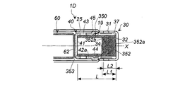
- the cup-shaped filter 350 has a peripheral wall portion 351, a bottom surface portion 352 having a large thickness in the axial X direction, and an opening portion facing the bottom surface portion 352, that is, on the opposite side to the bottom surface portion 352 in the axial direction.
- the bottom surface portion of the filter in the gas generator of this embodiment is a portion from the inner end surface 352b in the filter to the outer end surface 352a that contacts the closed end surface 32 of the diffuser portion.
- the outer peripheral surface of this bottom surface becomes the side surface of the bottom surface.
- the annular end surface 353 on the opening side is in contact with the bottom surface portion 41 of the cup-shaped member 40, and the outer end surface 352 a of the bottom surface portion 352 is in contact with the closed end surface 32 of the diffuser portion 30.
- the peripheral wall portion 351 is in contact with the peripheral wall portion 42 of the cup-shaped member 40 including the plurality of communication holes 43 from the inside.
- a second gap 37 is disposed between the gas outlet 31 and the gas outlet 31.
- the cup-shaped filter 350 is arranged so that the central axis of the cup-shaped filter 350 coincides with the axis X of the cylindrical housing 10.
- the communication hole 43 of the cup-shaped member 40 is formed near the annular end surface 353 of the cup-shaped filter 350 and at the position facing the first gap 25, and faces the peripheral wall portion 351 of the cup-shaped filter 350.
- the gas discharge port 31 of the diffuser part 30 is formed near the bottom surface part 352 of the cylindrical filter 350.
- L2 is within the range of L1. Therefore, the plurality of gas discharge ports 31 of the diffuser portion 30 face only the bottom surface portion 352 of the cup-shaped filter 350 with the second gap 37 interposed therebetween.
- the area A2 is about 70% when the total area of A1 and A2 is 100%.
- the gas generator 1D in FIG. 6 operates in the same manner as the gas generator 1 in FIG.
- the combustion gas passes through the peripheral wall portion 351 of the cup-shaped filter 350, passes through the inner end surface 352b and the bottom surface portion 352, enters the second gap 37, breaks the seal tape 34, and is discharged from the gas discharge port 31.
- the load acts to radially deform the peripheral wall portion 351 of the cup-shaped filter 350 facing the second gap 37. Even in such a case, since the bottom portion 352 of the cup-shaped filter 250 is thick in the axial direction, the peripheral wall portion 351 and the bottom portion 352 facing the second gap 37 are not easily deformed radially outward. ing.
- the combustion gas passes through the peripheral wall portion 351 and the bottom surface portion 352 facing the second gap 37, and the cooling and filtering effect is enhanced. Since the filter function as designed is exhibited in this way, the gas generator has a stable output and a high output reproducibility. In addition, since the combustion gas passes through one cup-shaped filter 350 twice, the cooling effect and the filtering effect can be enhanced as compared with a mode in which the combustion gas passes only once. Furthermore, compared with the form which arrange
- FIG. 8 Gas Generator in FIG. 8
- the gas generator 1E in FIG. 8 is the same as the gas generator 1D in FIG. 6 except that a part of the shape of the filter is different.
- the cup-shaped filter 350A has an annular portion 354 protruding outward in the radial direction on the outer end surface 352a side of the bottom surface portion 352.
- the annular part 354 is in contact with both the closed end face 32 and the peripheral wall part 33 of the diffuser part 30 to support the bottom face part 352 side of the cup-shaped filter 350A from the radial direction.
- the gas generator 1F in FIG. 9 is the same as the gas generator 1D in FIG. 6 except that a part of the filter and a part of the diffuser are different. is there.
- the cup-shaped filter 350B has a recess 355 in the center portion of the bottom surface 352 on the outer end surface 352a side.
- the closed end face 32 of the diffuser part 30 has a convex part 36 protruding inward at the center part.
- the convex portion 36 of the closed end face 32 of the diffuser portion 30 is fitted into the concave portion 355 of the cup-shaped filter 350B, and the convex portion 36 and the concave portion 355 are fitted together.
- the filter 350B is supported in the radial direction.
Landscapes
- Engineering & Computer Science (AREA)
- Mechanical Engineering (AREA)
- Physics & Mathematics (AREA)
- Fluid Mechanics (AREA)
- Air Bags (AREA)
Abstract
本発明は、筒状ハウジングにおいて、 筒状ハウジング本体部内の燃焼室とディフューザ部との間がカップ状部材で仕切られ、 前記カップ状部材が、底面部が筒状ハウジング本体部の第1端部側に位置し、開口部が筒状ハウジング本体部の第2端部側に位置し、複数の連通孔が形成された周壁部が、前記筒状ハウジング本体部の内壁面との間に、前記燃焼室と前記ディフューザ部を連通する第1間隙を形成するように配置され、 前記カップ状部材と前記ディフューザ部で囲まれた空間内にフィルタが配置され、 前記フィルタが、底面部、周壁部および開口部を有するカップ状であり、 前記フィルタの底面部が前記ディフューザ部の閉塞端面に当接され、前記開口部の端面が前記カップ状部材の底面部に対向され、前記周壁部が、前記複数の連通孔を含む前記カップ状部材の周壁部に内側から当接され、かつ前記ガス排出口との間に第2間隙をおいて配置される、ガス発生器である。
Description
本発明は、自動車に搭載するエアバッグ装置に使用できるガス発生器に関する。
背景技術
DE202005008938Uには、ガス源として加圧ガスとガス発生剤を併用したハイブリッドタイプのガス発生器が開示されている。加圧ガスが充填されたボトルの一端側には、ガス発生剤12および点火装置10が取り付けられたハウジングが配置されている。またその反対端部側には、周壁部30に放射状の開口28が形成され、フィルタ24が内部に収容されたハウジングが配置されている。ボトルの一端側のインレットポート16がインレット膜18によって閉塞され、反対端側の排出開口20が排出開口膜22によって閉塞されている。このガス発生器は、フィルタ24は加圧ガスが充填されたボトルの外部であり、排出開口20に隣接した位置に配置されている。
DE202005008938Uには、ガス源として加圧ガスとガス発生剤を併用したハイブリッドタイプのガス発生器が開示されている。加圧ガスが充填されたボトルの一端側には、ガス発生剤12および点火装置10が取り付けられたハウジングが配置されている。またその反対端部側には、周壁部30に放射状の開口28が形成され、フィルタ24が内部に収容されたハウジングが配置されている。ボトルの一端側のインレットポート16がインレット膜18によって閉塞され、反対端側の排出開口20が排出開口膜22によって閉塞されている。このガス発生器は、フィルタ24は加圧ガスが充填されたボトルの外部であり、排出開口20に隣接した位置に配置されている。
本発明の開示
本発明は、筒状ハウジング本体部とディフューザ部からなる筒状ハウジングを有しており、
前記筒状ハウジング本体部の第1端部側に点火装置を有し、前記第1端部とは軸方向反対側の第2端部側が複数のガス排出口を有するディフューザ部により閉塞されており、
前記筒状ハウジング本体部の内部空間にガス発生剤を含む燃焼室が存在し、
前記燃焼室と前記ディフューザ部との間がカップ状部材により仕切られており、
前記カップ状部材が、底面部、複数の連通孔が形成された周壁部、および開口部を有しており、前記底面部が第1端部側に位置し、前記開口部が第2端部側に位置し、前記周壁部が、半径方向外側に対向している前記筒状ハウジング本体部の内壁面との間に、前記燃焼室と前記ディフューザ部を連通する第1間隙が形成されるように配置されているものであり、
さらに前記カップ状部材と前記ディフューザ部で囲まれた空間内にフィルタが配置されており、
前記フィルタが、底面部、周壁部および開口部を有しているカップ状のフィルタであり、
前記フィルタの底面部が前記ディフューザ部の閉塞端面に当接され、前記開口部の端面が前記カップ状部材の底面部に対向されており、さらに前記周壁部が、前記複数の連通孔を含む前記カップ状部材の周壁部に内側から当接され、かつ前記ガス排出口との間に第2間隙をおいて配置されているものである、ガス発生器である。
本発明は、筒状ハウジング本体部とディフューザ部からなる筒状ハウジングを有しており、
前記筒状ハウジング本体部の第1端部側に点火装置を有し、前記第1端部とは軸方向反対側の第2端部側が複数のガス排出口を有するディフューザ部により閉塞されており、
前記筒状ハウジング本体部の内部空間にガス発生剤を含む燃焼室が存在し、
前記燃焼室と前記ディフューザ部との間がカップ状部材により仕切られており、
前記カップ状部材が、底面部、複数の連通孔が形成された周壁部、および開口部を有しており、前記底面部が第1端部側に位置し、前記開口部が第2端部側に位置し、前記周壁部が、半径方向外側に対向している前記筒状ハウジング本体部の内壁面との間に、前記燃焼室と前記ディフューザ部を連通する第1間隙が形成されるように配置されているものであり、
さらに前記カップ状部材と前記ディフューザ部で囲まれた空間内にフィルタが配置されており、
前記フィルタが、底面部、周壁部および開口部を有しているカップ状のフィルタであり、
前記フィルタの底面部が前記ディフューザ部の閉塞端面に当接され、前記開口部の端面が前記カップ状部材の底面部に対向されており、さらに前記周壁部が、前記複数の連通孔を含む前記カップ状部材の周壁部に内側から当接され、かつ前記ガス排出口との間に第2間隙をおいて配置されているものである、ガス発生器である。
本発明は、以下の詳細な説明と添付された図面により、さらに完全に理解されるものであるが、これらはただ説明のため付されるものであり、本発明を制限するものではない。
発明の詳細な説明
DE202005008938Uのようなフィルタの配置であると、排出開口20から排出されたガスが集中して、フィルタ24への負荷が大きくなり、冷却効果も十分ではないと考えられる。さらに、ディフューザに相当する部材32の内部全体がフィルタ24で占められており、放射状の開口28にもフィルタ24が接触している構造は、フィルタ全体をガスが通過し難くなり、フィルタの機能が発揮し難くなることが考えられる。
DE202005008938Uのようなフィルタの配置であると、排出開口20から排出されたガスが集中して、フィルタ24への負荷が大きくなり、冷却効果も十分ではないと考えられる。さらに、ディフューザに相当する部材32の内部全体がフィルタ24で占められており、放射状の開口28にもフィルタ24が接触している構造は、フィルタ全体をガスが通過し難くなり、フィルタの機能が発揮し難くなることが考えられる。
本件発明のガス発生器は、燃焼ガスの圧力によりフィルタが半径方向外側に膨張変形することがなく、フィルタとガス排出口の間の空間が確保できる。このため、設計どおりのフィルタ機能が発揮され、ガス発生器の出力が安定することから、出力再現性が高いガス発生器となる。
本発明で使用している筒状ハウジングは、鉄、ステンレスなどの金属製であり、筒状ハウジング本体部とディフューザ部からなるものである。筒状ハウジング本体部とディフューザ部は、溶接により接合されたものでもよいし、予め一体成形されたものでもよい。
点火装置は、公知のガス発生器で使用されている電気式点火器、または電気式点火器と伝火薬の組み合わせを使用することができる。前記伝火薬としては、公知のガス発生剤や黒色火薬などを使用することもできる。
ディフューザ部のガス排出口は、筒状ハウジング(ディフューザ部)の周壁部に複数が形成されており、シールテープなどの閉塞手段で閉塞されている。
燃焼室に充填されたガス発生剤は、公知のガス発生器で使用されているものを使用することができる。
燃焼室とディフューザ部との間はカップ状部材により仕切られている。ここで「仕切られている」とは、燃焼室空間とディフューザ部の内部空間がカップ状部材で分けられているが、燃焼室からディフューザ部へのガス排出経路は確保されていることを意味している。燃焼室からディフューザ部へのガス排出経路は、燃焼室、第1間隙、複数の連通孔、カップ状フィルタおよびディフューザ部からなるガス排出経路である。
カップ状部材は、筒状ハウジング本体部の内壁面との間に燃焼室とディフューザ部を連通する第1間隙が形成されるように配置されていればよく、例えば、次のような形態で固定することができる。
(I)筒状ハウジング本体部とディフューザ部の間において、内側に突き出された環状突起(環状段差面)が形成されており、前記環状突起(環状段差面)にカップ状部材の開口部端面が当接された形態。
(II)前記(I)の形態にて、カップ状部材として開口部に拡径部を有するものを使用して、前記拡径部が前記環状突起(環状段差面)に当接された形態。
(III)前記(I)の形態にて、カップ状部材として底面部の外径(d1)と開口部の外径(d2)がd2>d1であり、底面部から開口部までの周壁部が傾斜面であるものを使用して、前記開口部端面が前記環状突起(環状段差面)に当接された形態。
(IV)筒状ハウジング本体部の内径(D1)とディフューザ部の内径(D2)をD1>D2とすることで境界部に環状段差面が形成されており、前記環状段差面に対して(I)、(II)または(III)のカップ状部材の開口部側が当接された形態。
(V)カップ状部材として、開口部に拡径部を有し、さらに拡径部から底面部方向への折り返し部を有しているものを使用して、折り返し部の外径と筒状ハウジングの内径が調整されることで、カップ状部材の折り返し部が筒状ハウジングの内壁面に対して圧入された形態。
(VI)カップ状部材として底面部の外径(d1)と開口部の外径(d2)がd2>d1であり、底面から開口部までの周壁部が傾斜面であり、さらに開口部に形成された拡径部から底面部方向への折り返し部を有しているものを使用して、折り返し部の外径と筒状ハウジングの内径が調整されることで、カップ状部材の折り返し部が筒状ハウジングの内壁面に対して圧入された形態。
フィルタは、底面部が前記ディフューザ部の閉塞端面に当接され、開口部の端面がカップ状部材の底面部に対向するように、例えばカップ状部材に対してフィルタを圧入したり、カップ状部材の周壁部の内周面に突起を設け開口部側をその突起に当接させたりして、軸方向の移動を阻止している。またフィルタの開口部は、カップ状部材の底面部に当接させてもよい。フィルタは、周壁部が、複数の連通孔を含むカップ状部材の周壁部に内側から当接されることで半径方向から支持されている。フィルタは、ガス排出口との間に第2間隙をおいて配置されていることで、第2間隙に面したフィルタの全面においてガスを通過させることができるため、フィルタ機能が十分に発揮される。
本発明のガス発生器においては、燃焼室内のガス発生剤の燃焼により発生した燃焼ガスは、燃焼室、第1間隙、複数の連通孔からカップ状フィルタの開口部側端面寄りの周壁部を通ったあと、フィルタ内に入る。その後、同じカップ状フィルタの第2間隙に面した周壁部を通ったあと、シールテープを破ってガス排出口から排出される。
このような動作をする本発明のガス発生器は、次の(i)~(iii)の効果を得ることができる。
(i)フィルタとして均一厚みの筒状フィルタを使用している場合には、燃焼ガスが筒状フィルタ内に流入して圧力が高まると、第2間隙に面した周壁部が半径方向外側に膨張して、第2間隙を狭くすることが考えられる。このように第2間隙が狭くなると、燃焼ガスはガス排出口に面した筒状フィルタの周壁部のみを通過し易くなってしまい、冷却および濾過効果が低下する。また、フィルタの周壁部が半径方向外側に膨張するとディフューザ部端面との当接が外れて、燃焼ガスがショートパスし、すなわち燃焼ガスの一部がフィルタを通過せずにガス排出口に到達してしまい、冷却及び濾過効果が低下する。
本発明のガス発生器では、フィルタの底面部がディフューザ部の閉塞端面に当接するように配置されているため、フィルタの内側から外側に流れる燃焼ガスによる荷重が発生したときでも、第2間隙に面したフィルタの底面部および底面部側の周壁部は変形し難い。このため、第2間隙が狭くなり難く、フィルタの第2間隙に面した周壁部の全面で冷却および濾過をすることができる。それにより設計どおりのフィルタ機能が発揮され、ガス発生器の出力が安定することから、出力再現性が高いガス発生器となる。つまり(i)の効果は、従来の筒状フィルタにおける一端部の肉厚を部分的に大きくした状態であり、その一端部が底面部に相当する。そしてそのようなフィルタを第2間隙と組み合わせて配置することで、一番変形しやすい部分に対して構造上の補強が得られる点にある。そのためフィルタは、底面部が完全に閉じているものに限定せず、ガス発生器を通常モードで作動させるときの変形防止機能を果たすものであれば、フィルタ底面部に開口部の径よりも小さい径の孔が形成されていてもよい。
(ii)燃焼ガスが同じフィルタを二度通過することで、燃焼ガスが一度しかフィルタを通過しない形態と比べると、冷却効果および濾過効果を高めることができ、フィルタを二箇所に分けて配置する形態と比べると、フィルタ量を減少させることができるほか、部品数も減少させることができる。
(iii)さらに燃焼ガスが、フィルタの凹凸面と接触しやすく、その面積も大きいため、燃焼ガスに含まれている燃焼残渣がカップ状フィルタに付着され易くなり、捕捉され易くなる。
本発明のガス発生器の好ましい態様は、前記フィルタが、底面部、周壁部、開口部および前記底面部から半径方向外側に突き出された環状部を有しているカップ状のフィルタであり、
前記フィルタの底面部が前記ディフューザ部の閉塞端面に当接され、前記環状部が前記ディフューザ部の閉塞端面と周壁部に当接され、前記開口部の端面が前記カップ状部材の底面部に当接されており、さらに前記周壁部が、前記複数の連通孔を含む前記カップ状部材の周壁部に内側から当接され、かつ前記ガス排出口との間に第2間隙をおいて配置されているものである。
前記フィルタの底面部が前記ディフューザ部の閉塞端面に当接され、前記環状部が前記ディフューザ部の閉塞端面と周壁部に当接され、前記開口部の端面が前記カップ状部材の底面部に当接されており、さらに前記周壁部が、前記複数の連通孔を含む前記カップ状部材の周壁部に内側から当接され、かつ前記ガス排出口との間に第2間隙をおいて配置されているものである。
この態様は、フィルタの底面部から半径方向外側に突き出された環状部を有しており、前記環状部がディフューザ部の閉塞端面と周壁部の両方に当接されているため、環状部の幅は、第2間隙の幅と実質的に同一である。この態様のガス発生器では、燃焼ガスの流れによってフィルタ内部から外部へ荷重がかかったときに、第2間隙に面した底面部および底面部側の周壁部は膨張し難くなっている。この態様では、環状部を配置すること自体が周壁部の肉厚を部分的に増すことと同じであり、底面部と組み合わせてさらに第2間隙が狭くなり難く、フィルタの第2間隙に面した周壁部の全面で冷却および濾過をすることができる。
本発明のガス発生器のさらに好ましい態様は、前記フィルタが、前記カップ状部材側の内径(r1)の大きな第1周壁部と、前記ディフューザ部側の内径(r2)の小さな第2周壁部を有し(r1>r2)、前記第1周壁部と前記第2周壁部の間に前記内径差により形成された環状面を有している筒状フィルタであり、
前記筒状フィルタの第2周壁部側の端面が前記ディフューザ部の閉塞端面に当接され、前記第1周壁部側の端面が前記カップ状部材の底面部に当接され、前記第1周壁部が、前記複数の連通孔を含む前記カップ状部材の周壁部に内側から当接され、前記第2周壁部が前記ガス排出口との間に第2間隙をおいて配置されているものであり、
前記カップ状部材の複数の連通孔が前記筒状フィルタの第1周壁部のみに面しており、前記ディフューザ部の複数のガス排出口が、前記第2間隙を挟んで前記筒状フィルタの第2周壁部のみに面しているものである。
前記筒状フィルタの第2周壁部側の端面が前記ディフューザ部の閉塞端面に当接され、前記第1周壁部側の端面が前記カップ状部材の底面部に当接され、前記第1周壁部が、前記複数の連通孔を含む前記カップ状部材の周壁部に内側から当接され、前記第2周壁部が前記ガス排出口との間に第2間隙をおいて配置されているものであり、
前記カップ状部材の複数の連通孔が前記筒状フィルタの第1周壁部のみに面しており、前記ディフューザ部の複数のガス排出口が、前記第2間隙を挟んで前記筒状フィルタの第2周壁部のみに面しているものである。
筒状フィルタは、第1周壁部側の第1環状端面がカップ状部材の底面部に当接され、第2環状端面がディフューザ部の閉塞端面に当接されている。第2環状端面がディフューザ部の閉塞端面に当接することで閉塞され、実質的にカップ状フィルタとなっている。
この態様のガス発生器は、内径(r1)の大きな第1周壁部と、内径(r2)の小さな第2周壁部を有し、第1周壁部と第2周壁部の間に内径差により形成された環状面を有したフィルタを使用している。第1周壁部は開口部の側で第2周壁部は底面の側になる。第1周壁部の内径(r1)と第2周壁部の内径(r2)は、r1>r2の関係であるから、第1周壁部の半径方向の幅(w1)と第2周壁部の半径方向の幅(w2)は、w2>w1の関係になる。w2/w1は、1.2~3.8の範囲が好ましい。なお、フィルタの外径は一定である。
この態様のガス発生器では、ディフューザ部の複数のガス排出口は、第2間隙を挟んで筒状フィルタの半径方向の厚みの大きな第2周壁部のみに面している。燃焼ガスの流れによってフィルタ内部から外部へ荷重がかかったときでも、第2周壁部および第2周壁部に接した第1周壁部は変形し難く、第2間隙が狭くなり難くなっているため、フィルタの第2間隙に面した第1周壁部および第2周壁部の全面で冷却および濾過をすることができる。また、第2周壁部の半径方向の厚みが大きく、その分だけフィルタ量が増加して濾過機能が高められているが、第2周壁部で囲まれた中心孔と環状面の両方からも燃焼ガスが通過するため、燃焼ガスの排出性能は維持されている。つまり本態様では、周壁部のうち変形しやすい部分の肉厚を大きくするもので、環状面と合わせて、燃焼ガスとの接触面積の増加によって冷却効率や濾過効率が向上する。なお、この態様では、第1周壁部と第2周壁部の長さを調整することで、第2周壁部が第2間隙の全体に対して半径方向に対向できるようにすることもできる。
本発明のガス発生器のさらに好ましい態様は、前記フィルタが、底面部、周壁部および開口部を有しているカップ状フィルタであり、前記底面部の軸方向の厚さが、前記周壁部の半径方向の厚さよりも大きく、
前記カップ状フィルタの底面部が前記ディフューザ部の閉塞端面に当接され、前記開口部の端面が前記カップ状部材の底面部に当接されており、前記周壁部が、前記複数の連通孔を含む前記カップ状部材の周壁部に内側から当接され、前記底面部の側面が、前記ガス排出口との間に第2間隙をおいて配置されているものであり、
前記カップ状部材の複数の連通孔が前記カップ状フィルタの周壁部のみに面しており、前記ディフューザ部の複数のガス排出口が、前記第2間隙を挟んで前記カップ状フィルタの底面部の側面のみに面しているものである。
前記カップ状フィルタの底面部が前記ディフューザ部の閉塞端面に当接され、前記開口部の端面が前記カップ状部材の底面部に当接されており、前記周壁部が、前記複数の連通孔を含む前記カップ状部材の周壁部に内側から当接され、前記底面部の側面が、前記ガス排出口との間に第2間隙をおいて配置されているものであり、
前記カップ状部材の複数の連通孔が前記カップ状フィルタの周壁部のみに面しており、前記ディフューザ部の複数のガス排出口が、前記第2間隙を挟んで前記カップ状フィルタの底面部の側面のみに面しているものである。
この態様のガス発生器におけるフィルタの底面部とは、フィルタ内の内側端面からディフューザ部の閉塞端面に当接する外側端面までの部分である。この底面部の外周面が底面部の側面となる。すなわち、この態様のガス発生器は、フィルタの底面部の軸方向の厚みが大きくなっており、ガス排出口は、第2間隙を挟んでフィルタの底面部の側面(軸方向の厚みが増した部分)のみに面している。このようなフィルタの底面部の軸方向の厚み、は、少なくともディフューザ部の閉塞端面からガス排出口のカップ状部材側の端部までの範囲である。この態様のガス発生器では、燃焼ガスの流れによってフィルタ内部から外部へ荷重がかかったとき、厚みの大きな底面部は変形し難くなっている。このため、第2間隙が狭くなり難く、フィルタの第2間隙に面した第1周壁部および底面部の全面で冷却および濾過をすることができる。また、底面部の軸方向の厚みが大きく、その分だけフィルタ量が増加して濾過機能が高められているが、底面部の開口部側の面からも燃焼ガスが通過するため、燃焼ガスの排出性能は維持されている。なお、この態様では、底面部の軸方向の厚みを調整することで、底面部が第2間隙の全体に対して半径方向に対向できるようにすることもできる。
本発明のガス発生器のさらに好ましい態様は、前記フィルタが、凹部を有している底面部、周壁部および開口部を有しているカップ状フィルタであり、
前記ディフューザ部が、閉塞端面から内側に突き出された凸部を有しており、
前記ディフューザ部の閉塞端面の凸部が、前記カップ状フィルタの凹部に嵌め込まれているものである。
前記ディフューザ部が、閉塞端面から内側に突き出された凸部を有しており、
前記ディフューザ部の閉塞端面の凸部が、前記カップ状フィルタの凹部に嵌め込まれているものである。
フィルタの底面部の凹部とディフューザ部の閉塞端面から内側に突き出された凸部を嵌め合わせることで、底面部の厚みの大きなフィルタが半径方向にずれないように支持することができる。
本発明のガス発生器のさらに好ましい態様は、前記カップ状フィルタの底面部が、前記底面部の端面から前記開口部の端面までの長さをLとするとき0.3~0.7LとなるL1の長さを有しているものであり、
前記ディフューザ部の閉塞端面の内側面から前記ガス排出口の前記カップ状部材側の端部までの長さが、前記Lを基準とすると0.35~0.55LとなるL2の範囲内のものである。
前記ディフューザ部の閉塞端面の内側面から前記ガス排出口の前記カップ状部材側の端部までの長さが、前記Lを基準とすると0.35~0.55LとなるL2の範囲内のものである。
フィルタの底面部の厚みとガス排出口の位置を調整してL2がL1の範囲内になるようにすることで、フィルタによる燃焼ガスの冷却および濾過効果を高めることができる。
本発明のガス発生器は、フィルタの形状と他部品との間の配置状態が調整されており、作動時における燃焼ガスの圧力によりフィルタが半径方向外側に変形することがないため、フィルタとガス排出口の間の空間となる第2間隙が確保できる。このため、設計どおりのフィルタ機能が発揮され、ガス発生器の出力が安定することから、出力再現性が高いガス発生器となる。
本発明のガス発生器は、各種自動車に搭載されるエアバッグ装置用のガス発生器として利用することができる。
発明の実施の形態
(1)図1のガス発生器
図1に示すガス発生器1は、外殻容器である筒状ハウジング10が筒状ハウジング本体部11とディフューザ部30からなるものである。筒状ハウジング本体部11とディフューザ部30は、ステンレスなどの金属製である。
(1)図1のガス発生器
図1に示すガス発生器1は、外殻容器である筒状ハウジング10が筒状ハウジング本体部11とディフューザ部30からなるものである。筒状ハウジング本体部11とディフューザ部30は、ステンレスなどの金属製である。
筒状ハウジング本体部11の第1端部12a側には、点火器15が取り付けられている。点火器15は、着火部16を有する点火器本体部が点火器カラー17に固定されているものである。必要に応じて公知の伝火薬を併用することができる。点火器カラー17と筒状ハウジング本体部11の内壁面11aの間には、防湿のためのOリング18が配置されている。
筒状ハウジング本体部11の第1端部12aとは軸X方向反対側の第2端部12b側は、ガス排出口31を有するディフューザ部30により閉塞されている。ディフューザ部30は、閉塞端面32と周壁部33を有している。図1に示す実施形態では、筒状ハウジング本体部11とディフューザ30は、溶接部19において溶接されている。ガス排出口31は、複数が周方向に均等間隔で形成されており、内側からアルミニウム製のシールテープ34で閉塞されている。図1に示す実施形態では、筒状ハウジング本体部11とディフューザ部30との境界部に環状段差面35が形成されている。環状段差面35は、筒状ハウジング本体部11の内径(D1)とディフューザ部30の内径(D2)をD1>D2とすることで形成されている。図1では筒状ハウジング本体部11の大部分とディフューザ部30はそれぞれ一定の内径である。
筒状ハウジング本体部11の内部空間は、ガス発生剤21を含む燃焼室20である。燃焼室20内には、必要に応じてガス発生剤21の充填量に応じて燃焼室20の容積を調整するためのリテーナが配置されていてもよい。
燃焼室20とディフューザ部30の間は、カップ状部材40により仕切られている。カップ状部材40は、鉄、ステンレスなどからなるものであり、図1に示すように、底面部41、連通孔43が形成された周壁部42、および開口部44を有しているものである。連通孔43は、複数個が周方向に等間隔で形成されている。カップ状部材40の開口部44側の端面は、周壁部42から外側に拡がった拡径部45を有している。カップ状部材40は、拡径部45の外径の寸法と筒状ハウジング本体部11の内径の寸法を調整して、ハウジング本体部11に圧入することができる。
カップ状部材40とディフューザ部30で囲まれた空間内には、カップ状フィルタ50が配置されている。カップ状フィルタ50は、周壁部51、底面部52および底面部52に対向する開口部を有している。カップ状フィルタ50は、底面部52がディフューザ部30の閉塞端面32に当接され、開口部の環状端面53がカップ状部材40の底面部41に当接されている。カップ状フィルタ50は、周壁部51が、複数の連通孔43を含むカップ状部材40の周壁部42に内側から当接され、すなわち周壁部42の内壁42aに当接し、かつガス排出口31との間に第2間隙37が形成されるように配置されている。カップ状フィルタ50は、カップ状フィルタ50の中心軸が筒状ハウジング10の軸Xと一致するように配置されている。
カップ状部材40の連通孔43は、カップ状フィルタ50の環状端面53寄りで、かつ第1間隙25に面した位置になるように形成されている。 ディフューザ部30のガス排出口31は、カップ状フィルタ50の底面部52寄りになるように形成されている。カップ状部材40の複数の連通孔43は、カップ状フィルタ50の周壁部51に面しており、ディフューザ部30の複数のガス排出口31は、第2間隙37を挟んでカップ状フィルタ50の周壁部51に面している。カップ状フィルタ50の周壁部51とカップ状部材40の周壁部42が当接されている面積(A1)と、カップ状フィルタ50の周壁部51の第2間隙37に面している面積(A2)は、A1とA2の合計面積を100%とするとき、A2が約70%である。
筒状ハウジング本体部11内には、さらに第1端部12a側が開口され、第2端部12b側が閉塞された筒状支持部材60が配置されている。筒状支持部材60は、内側にガス発生剤を収容する充填空間を形成するとともにカップ状部材40とカップ状フィルタ50を軸X方向に支持するために使用されているものであり、カップ状部材40が固定され、第1間隙25が確保されている場合には使用しなくてもよい。なお、充填空間も燃焼室に含まれる。筒状支持部材60は、ステンレスなどの金属からなるものである。
筒状支持部材60は、筒状ハウジング本体部11の内径よりも小さな外径を有しており、筒状支持部材60と筒状ハウジング本体部11の間には筒状間隙65が形成されている。筒状支持部材60は、周壁部61に複数のガス通過孔63が軸方向および周方向に均等間隔で形成されている。燃焼室20と筒状間隙65は、ガス通過孔63で連通されている。筒状支持部材60は、点火器15側の開口部に拡径部66を有しており、拡径部66の外周縁部66aが筒状ハウジング本体部11の内壁面11aに当接されており、閉塞端面62はカップ状部材40の底面部41に当接されている。
外周縁部66aの外径は、筒状ハウジング本体部11の内径よりも僅かに大きくなっており、筒状ハウジング本体部11内に配置されたとき、拡径部66が有する弾性により、筒状ハウジング本体部11の内壁面11aに対して圧入されている。拡径部66が環状に形成されている場合、圧入された部分には隙間が形成されない。
図1に示すガス発生器1の動作を説明する。
点火器15が作動して燃焼室20内のガス発生剤21が着火燃焼され、燃焼ガスが発生する。燃焼ガスは、筒状支持部材60のガス通過孔63を通って筒状間隙65と充填空間との間を出入りしながら第2端部12bの方向に流れて行く。その後、第1間隙25に至り、そこから連通孔43とカップ状フィルタ50の環状端面53寄りの周壁部51を通って、ディフューザ部30内に入り、再度、カップ状フィルタ50の第2間隙37に面した周壁部51を通って第2間隙37に入る。その後、燃焼ガスはシールテープ34を破り、ガス排出口31から排出される。
燃焼ガスがカップ状フィルタ50の内側から外側に流れると、その荷重が第2間隙37に面したカップ状フィルタ50の周壁部51に対して半径方向外側に変形させるように作用する。このような場合でも、カップ状フィルタ50は底面部52を有しているため、第2間隙37に面した周壁部51は半径方向外側には変形し難くなっている。このため、燃焼ガスは、第2間隙37に面した周壁部51の全体を通過するようになり、冷却および濾過効果が高められる。
このように設計どおりのフィルタ機能が発揮されることから、ガス発生器の出力が安定して、出力再現性が高いガス発生器となる。また燃焼ガスが一つのカップ状フィルタ50を二度通過するため、燃焼ガスが一度しかフィルタを通過しない形態と比べると、冷却効果および濾過効果を高めることができる。さらにフィルタを複数箇所に分けて配置する形態と比べると、フィルタ量を減少させることやフィルタの固定に必要な部材を省略することができる。さらに燃焼ガスが筒状フィルタ50の内側に入ると内壁面の凹凸によって、燃焼ガスに含まれている燃焼残渣が付着されて捕捉され易くなる。そしてカップ状フィルタの内側の空間が、燃焼残渣捕集空間として機能する。
(2)図2のガス発生器
図2のガス発生器1Aは図1のガス発生器1に対して、フィルタの形状が異なっているほかは、同じものである。
図2のガス発生器1Aは図1のガス発生器1に対して、フィルタの形状が異なっているほかは、同じものである。
カップ状フィルタ150は、周壁部151、底面部152、底面部152に対向する、すなわち底面部152と軸方向反対側の開口部、および底面部152から半径方向外側に突き出された環状部154を有している。カップ状フィルタ150は、底面部152がディフューザ部30の閉塞端面32に当接され、環状部154がディフューザ部30の閉塞端面32と周壁部33に当接され、開口部側の環状端面153がカップ状部材40の底面部41に当接されている。カップ状フィルタ150は、周壁部151が複数の連通孔43を含むカップ状部材40の周壁部42に内側から当接され、すなわち周壁部42の内壁42aに当接し、ガス排出口31との間に第2間隙37をおいて配置されている。カップ状フィルタ150は、カップ状フィルタ150の中心軸が筒状ハウジング10の軸Xと一致するように配置されている。
カップ状部材40の連通孔43は、カップ状フィルタ150の環状端面153寄りで、かつ第1間隙25に面した位置に形成されている。ディフューザ部30のガス排出口31は、カップ状フィルタ150の底面部152寄りに形成されている。カップ状部材40の複数の連通孔43は、カップ状フィルタ150の周壁部151に面しており、ディフューザ部30の複数のガス排出口31は、第2間隙37を挟んでカップ状フィルタ150の周壁部151に面している。
カップ状フィルタ150の周壁部151とカップ状部材40の周壁部42が当接されている面積(A1)と、カップ状フィルタ150の周壁部151の第2間隙37に面している面積(A2)は、A1とA2の合計面積を100%とするとき、A2が約70%である。
図2のガス発生器1Aは、図1のガス発生器1と同様に動作する。燃焼ガスがカップ状フィルタ150の内側から外側に流れると、その荷重が第2間隙37に面したカップ状フィルタ150の周壁部151に対して半径方向外側に変形させるように作用する。このような場合でも、カップ状フィルタ150は底面部152を有しており、さらに環状部154がディフューザ部30の閉塞端面32と周壁部33に当接されているため、第2間隙37に面した周壁部151は半径方向外側には変形し難くなっている。このため、燃焼ガスは、第2間隙37に面した周壁部151の全体を通過するようになり、冷却および濾過効果が高められる。このように設計どおりのフィルタ機能が発揮されることから、ガス発生器の出力が安定して、出力再現性が高いガス発生器となる。また燃焼ガスが一つのカップ状フィルタ150を二度通過するため、燃焼ガスが一度しかフィルタを通過しない形態と比べると、冷却効果および濾過効果を高めることができる。さらにフィルタを複数箇所に分けて配置する形態と比べると、フィルタ量を減少させることやフィルタの固定に必要な部材を省略することができる。さらに燃焼ガスがカップ状フィルタ150の内側に入ると内壁面の凹凸によって、燃焼ガスに含まれている燃焼残渣が付着されて捕捉され易くなる。そしてカップ状フィルタの内側の空間が、燃焼残渣捕集空間として機能する。なお、図2の実施例では、製造時のシールテープ34と環状部154との干渉を回避するため、シールテープ34はディフューザ部30の周壁部33の外側に配置するか、周壁部33内側に貼り付ける場合は、ディフューザ部33の周壁部33の内周面のうち、シールテープ34を貼り付ける部分を切削して窪みを形成し、その窪みにシールテープ34を貼り付ける。
(3)図3のガス発生器
図3のガス発生器1Bは図1のガス発生器1に対して、フィルタの形状が異なっているほかは、同じものである。フィルタは底面部(閉塞端面)に中心孔255を形成した筒状である。
図3のガス発生器1Bは図1のガス発生器1に対して、フィルタの形状が異なっているほかは、同じものである。フィルタは底面部(閉塞端面)に中心孔255を形成した筒状である。
筒状フィルタ250の周壁部251は、カップ状部材40側の内径(r1)の大きな第1周壁部251aと、ディフューザ部30側の内径(r2)の小さな第2周壁部251bを有し、r1>r2の関係を満たしている。第1周壁部251aの半径方向の幅(w1)と第2周壁部251bの半径方向の幅(w2)は、w2>w1であり、w2/w1は約2.5である。筒状フィルタ250は、第1周壁部251aと第2周壁部251bの間に内径差(r1-r2)により形成された内側環状面256を有しており、第2周壁部251bで囲まれた中心孔255を有している。筒状フィルタ250は、カップ状部材40側の幅w1の第1環状端面253と軸方向反対側の幅w2の第2環状端面252を有している。第2周壁部251bの軸方向の長さL1は、図4に示すとおり、第2環状端面252(=閉塞端面32)から開口部の第1環状端面253までの長さをLとするときL1=0.3~0.7Lの長さを有している。
筒状フィルタ250は、第1周壁部251a側の第1環状端面253がカップ状部材40の底面部41に当接され、第2環状端面252がディフューザ部30の閉塞端面32に当接されて閉塞されることで、実質的にカップ状フィルタとなっている。筒状フィルタ250は、第1周壁部251aが複数の連通孔43を含むカップ状部材40の周壁部42に内側から当接され、すなわち周壁部42の内壁42aに当接し、第2周壁部251bがガス排出口31との間に第2間隙37をおいて配置されている。筒状フィルタ250は、筒状フィルタ250の中心軸が筒状ハウジング10の軸Xと一致するように配置されている。
カップ状部材40の連通孔43は、筒状フィルタ250の第2環状端面253寄りの第1間隙25に面した位置に形成されており、筒状フィルタ250の第1周壁部251aに面している。ディフューザ部30のガス排出口31は、筒状フィルタ250の第2環状端面252寄りに形成されている。
ディフューザ部30の閉塞端面32からガス排出口31のカップ状部材40側の端部までの長さL2は、図4に示すとおり、前記Lを基準とするとL2=0.35~0.55Lの範囲であり、L2はL1の範囲内である。このため、ディフューザ部30の複数のガス排出口31は、第2間隙37を挟んで筒状フィルタ250の第2周壁部251bのみに面している。
筒状フィルタ250の第1周壁部251aとカップ状部材40の周壁部42が当接されている面積(A1)と、筒状フィルタ150の第2周壁部251bの第2間隙37に面している面積(A2)は、A1とA2の合計面積を100%とするとき、A2が約70%である。
図3のガス発生器1Bは、図1のガス発生器1と同様に動作する。なお、燃焼ガスは、筒状フィルタ250の第1周壁部251aを通り、さらに内側環状面256および中心孔255から第2周壁部251bを通って第2間隙37に入り、シールテープ34を破ってガス排出口31から排出される。燃焼ガスが筒状フィルタ250の内側から外側に流れると、その荷重が第2間隙37に面した筒状フィルタ250の第2周壁部251bに対して半径方向外側に変形させるように作用する。このような場合でも、筒状フィルタ250の第2周壁部251bは第1周壁部251aと比べると半径方向の幅が大きくなっているため、第2間隙37に面した第2周壁部251bは半径方向外側には変形し難くなっている。このため、燃焼ガスは、第2間隙37に面した第1周壁部251aと第2周壁部251bを通過するようになり、冷却および濾過効果が高められる。このように設計どおりのフィルタ機能が発揮されることから、ガス発生器の出力が安定して、出力再現性が高いガス発生器となる。また燃焼ガスが一つの筒状フィルタ250を二度通過するため、燃焼ガスが一度しかフィルタを通過しない形態と比べると、冷却効果および濾過効果を高めることができる。さらにフィルタを複数箇所に分けて配置する形態と比べると、フィルタ量を減少させることやフィルタの固定に必要な部材を省略することができる。さらに燃焼ガスが筒状フィルタ250の内側に入ると内壁面の凹凸によって、燃焼ガスに含まれている燃焼残渣が付着されて捕捉され易くなる。そして筒状フィルタの内側の空間が、燃焼残渣捕集空間として機能する。
(4)図5のガス発生器
図5のガス発生器1Cは図3のガス発生器1Bに対して、フィルタの一部形状が異なっているほかは、同じものである。
図5のガス発生器1Cは図3のガス発生器1Bに対して、フィルタの一部形状が異なっているほかは、同じものである。
筒状フィルタ250は、カップ状部材40側の内径(r1)の大きな第1周壁部251aと、ディフューザ部40側の内径(r2)の小さな第2周壁部251bを有し(r1>r2)している。筒状フィルタ250は、第1環状端面253と第2環状端面252を有しており、第2環状端面252側に半径方向外側に突き出された環状部254を有している。環状部254は、ディフューザ部30の閉塞端面32と周壁部33の両方に当接されることで、筒状フィルタ250の第2環状端面252側を半径方向から支持している。
図5のガス発生器1Cは、図3のガス発生器1Bと同様に動作して、同様の効果が得られる。また環状部254の機能や効果は、図2のガス発生器1Aと同じである。
(5)図6のガス発生器
図6のガス発生器1Dは図1のガス発生器1に対して、フィルタの形状が異なっているほかは、同じものである。
図6のガス発生器1Dは図1のガス発生器1に対して、フィルタの形状が異なっているほかは、同じものである。
カップ状フィルタ350は、周壁部351、軸X方向の厚みの大きな底面部352、前記底面部352に対向する、すなわち底面部352と軸方向反対側の開口部を有している。この実施形態のガス発生器におけるフィルタの底面部とは、フィルタ内の内側端面352bからディフューザ部の閉塞端面32に当接する外側端面352aまでの部分である。この底面部の外周面が底面部の側面となる。
底面部352の軸X方向の厚さL1は、図7に示すとおり、底面部352の外側端面352a(=閉塞端面32)から開口部の環状端面353までの長さをLとするときL1=0.3~0.7Lの長さを有している。
カップ状フィルタは、開口部側の環状端面353がカップ状部材40の底面部41に当接され、底面部352の外側端面352aがディフューザ部30の閉塞端面32に当接されている。周壁部351は、複数の連通孔43を含むカップ状部材40の周壁部42に内側から当接され、すなわち周壁部42の内壁42aに当接し、軸X方向の厚みの大きな底面部352の側面が、ガス排出口31との間に第2間隙37をおいて配置されている。カップ状フィルタ350は、カップ状フィルタ350の中心軸が筒状ハウジング10の軸Xと一致するように配置されている。
カップ状部材40の連通孔43は、カップ状フィルタ350の環状端面353寄りで、かつ第1間隙25に面した位置に形成されており、カップ状フィルタ350の周壁部351に面している。ディフューザ部30のガス排出口31は、筒状フィルタ350の底面部352寄りに形成されている。ディフューザ部30の閉塞端面32からガス排出口31のカップ状部材40側の端部までの長さL2は、図7に示すとおり、前記Lを基準とするとL2=0.35~0.55Lの範囲であり、L2はL1の範囲内である。このため、ディフューザ部30の複数のガス排出口31は、第2間隙37を挟んでカップ状フィルタ350の底面部352のみに面している。カップ状フィルタ350の周壁部351とカップ状部材40の周壁部42が当接されている面積(A1)と、カップ状フィルタ350の周壁部351および底面部352の側面の第2間隙37に面している面積(A2)は、A1とA2の合計面積を100%とするとき、A2が約70%である。
図6のガス発生器1Dは、図1のガス発生器1と同様に動作する。なお、燃焼ガスは、カップ状フィルタ350の周壁部351を通り、さらに内側端面352bおよび底面部352を通って第2間隙37に入り、シールテープ34を破ってガス排出口31から排出される。燃焼ガスが筒状フィルタ250の内側から外側に流れると、その荷重が第2間隙37に面したカップ状フィルタ350の周壁部351に対して半径方向外側に変形させるように作用する。このような場合でも、カップ状フィルタ250の底面部352は軸方向の厚みが大きくなっているため、第2間隙37に面した周壁部351および底面部352は半径方向外側には変形し難くなっている。このため、燃焼ガスは、第2間隙37に面した周壁部351と底面部352を通過するようになり、冷却および濾過効果が高められる。このように設計どおりのフィルタ機能が発揮されることから、ガス発生器の出力が安定して、出力再現性が高いガス発生器となる。また燃焼ガスが一つのカップ状フィルタ350を二度通過するため、燃焼ガスが一度しかフィルタを通過しない形態と比べると、冷却効果および濾過効果を高めることができる。さらにフィルタを複数箇所に分けて配置する形態と比べると、フィルタ量を減少させることやフィルタの固定に必要な部材を省略することができる。さらに燃焼ガスがカップ状フィルタ350の内側に入ると内壁面の凹凸によって、燃焼ガスに含まれている燃焼残渣が付着されて捕捉され易くなる。そして筒状フィルタの内側の空間が、燃焼残渣捕集空間として機能する。
(6)図8のガス発生器
図8のガス発生器1Eは図6のガス発生器1Dに対して、フィルタの一部形状が異なっているほかは、同じものである。
図8のガス発生器1Eは図6のガス発生器1Dに対して、フィルタの一部形状が異なっているほかは、同じものである。
カップ状フィルタ350Aは、底面部352の外側端面352a側に半径方向外側に突き出された環状部354を有している。環状部354は、ディフューザ部30の閉塞端面32と周壁部33の両方に当接されることで、カップ状フィルタ350Aの底面部352側を半径方向から支持している。
図8のガス発生器1Eは、図6のガス発生器1Dと同様に動作して、同様の効果が得られる。また環状部354の機能や効果は、図2のガス発生器1Aと同じである。
(7)図9のガス発生器
図9のガス発生器1Fは、図6のガス発生器1Dに対してフィルタの一部形状およびディフューザ部の一部形状が異なっているほかは、同じものである。
図9のガス発生器1Fは、図6のガス発生器1Dに対してフィルタの一部形状およびディフューザ部の一部形状が異なっているほかは、同じものである。
カップ状フィルタ350Bは、底面部352の外側端面352a側の中心部分に凹部355を有しておる。ディフューザ部30の閉塞端面32は、中心部に内側に突き出された凸部36を有している。図9のガス発生器1Fは、ディフューザ部30の閉塞端面32の凸部36が、カップ状フィルタ350Bの凹部355に嵌め込まれており、凸部36と凹部355が嵌め合わされていることで、カップ状フィルタ350Bは半径方向に支持されている。
図9のガス発生器1Fは、図6のガス発生器1Dと同様に動作して、同様の効果が得られる。
本発明を以上のように記載した。当然、本発明は様々な形の変形をその範囲に含み、これら変形は本発明の範囲からの逸脱ではない。また当該技術分野における通常の知識を有する者が明らかに本発明の変形とみなすであろうすべては、以下に記載する請求項の範囲にある。
Claims (6)
- 筒状ハウジング本体部とディフューザ部からなる筒状ハウジングを有しており、
前記筒状ハウジング本体部の第1端部側に点火装置を有し、前記第1端部とは軸方向反対側の第2端部側が複数のガス排出口を有するディフューザ部により閉塞されており、
前記筒状ハウジング本体部の内部空間にガス発生剤を含む燃焼室が存在し、
前記燃焼室と前記ディフューザ部との間がカップ状部材により仕切られており、
前記カップ状部材が、底面部、複数の連通孔が形成された周壁部、および開口部を有しており、前記底面部が第1端部側に位置し、前記開口部が第2端部側に位置し、前記周壁部が、半径方向外側に対向している前記筒状ハウジング本体部の内壁面との間に、前記燃焼室と前記ディフューザ部を連通する第1間隙が形成されるように配置されているものであり、
さらに前記カップ状部材と前記ディフューザ部で囲まれた空間内にフィルタが配置されており、
前記フィルタが、底面部、周壁部および開口部を有しているカップ状のフィルタであり、
前記フィルタの底面部が前記ディフューザ部の閉塞端面に当接され、前記開口部の端面が前記カップ状部材の底面部に対向されており、さらに前記周壁部が、前記複数の連通孔を含む前記カップ状部材の周壁部に内側から当接され、かつ前記ガス排出口との間に第2間隙をおいて配置されているものである、ガス発生器。 - 前記フィルタが、底面部、周壁部、開口部および前記底面部から半径方向外側に突き出された環状部を有しているカップ状のフィルタであり、
前記フィルタの底面部が前記ディフューザ部の閉塞端面に当接され、前記環状部が前記ディフューザ部の閉塞端面と周壁部に当接され、前記開口部の端面が前記カップ状部材の底面部に当接されており、さらに前記周壁部が、前記複数の連通孔を含む前記カップ状部材の周壁部に内側から当接され、かつ前記ガス排出口との間に第2間隙をおいて配置されているものである、請求項1記載のガス発生器。 - 前記フィルタが、前記カップ状部材側の内径(r1)の大きな第1周壁部と、前記ディフューザ部側の内径(r2)の小さな第2周壁部を有し(r1>r2)、前記第1周壁部と前記第2周壁部の間に前記内径差により形成された環状面を有している筒状フィルタであり、
前記筒状フィルタの第2周壁部側の端面が前記ディフューザ部の閉塞端面に当接され、前記第1周壁部側の端面が前記カップ状部材の底面部に当接され、前記第1周壁部が、前記複数の連通孔を含む前記カップ状部材の周壁部に内側から当接され、前記第2周壁部が前記ガス排出口との間に第2間隙をおいて配置されているものであり、
前記カップ状部材の複数の連通孔が前記筒状フィルタの第1周壁部のみに面しており、前記ディフューザ部の複数のガス排出口が、前記第2間隙を挟んで前記筒状フィルタの第2周壁部のみに面しているものである、請求項1記載のガス発生器。 - 前記フィルタが、底面部、周壁部および開口部を有しているカップ状フィルタであり、前記底面部の軸方向の厚さが、前記周壁部の半径方向の厚さよりも大きく、
前記カップ状フィルタの底面部が前記ディフューザ部の閉塞端面に当接され、前記開口部の端面が前記カップ状部材の底面部に当接されており、前記周壁部が、前記複数の連通孔を含む前記カップ状部材の周壁部に内側から当接され、前記底面部の側面が、前記ガス排出口との間に第2間隙をおいて配置されているものであり、
前記カップ状部材の複数の連通孔が前記カップ状フィルタの周壁部のみに面しており、前記ディフューザ部の複数のガス排出口が、前記第2間隙を挟んで前記カップ状フィルタの底面部の側面のみに面しているものである、請求項1記載のガス発生器。 - 前記フィルタが、凹部を有している底面部、周壁部および開口部を有しているカップ状フィルタであり、
前記ディフューザ部が、閉塞端面から内側に突き出された凸部を有しており、
前記ディフューザ部の閉塞端面の凸部が、前記カップ状フィルタの凹部に嵌め込まれているものである、請求項4記載のガス発生器。 - 前記カップ状フィルタの底面部が、前記底面部の端面から前記開口部の端面までの長さをLとするとき0.3~0.7LとなるL1の長さを有しているものであり、
前記ディフューザ部の閉塞端面の内側面から前記ガス排出口の前記カップ状部材側の端部までの長さが、前記Lを基準とすると0.35~0.55LとなるL2の範囲内のものである、請求項4または5記載のガス発生器。
Priority Applications (4)
| Application Number | Priority Date | Filing Date | Title |
|---|---|---|---|
| KR1020197000860A KR20190032349A (ko) | 2016-07-26 | 2017-07-03 | 가스 발생기 |
| DE112017003777.8T DE112017003777T5 (de) | 2016-07-26 | 2017-07-03 | Gasgenerator |
| US16/313,295 US10723308B2 (en) | 2016-07-26 | 2017-07-03 | Gas generator |
| CN201780044354.8A CN109476273B (zh) | 2016-07-26 | 2017-07-03 | 气体发生器 |
Applications Claiming Priority (2)
| Application Number | Priority Date | Filing Date | Title |
|---|---|---|---|
| JP2016146333A JP6650365B2 (ja) | 2016-07-26 | 2016-07-26 | ガス発生器 |
| JP2016-146333 | 2016-07-26 |
Publications (1)
| Publication Number | Publication Date |
|---|---|
| WO2018020960A1 true WO2018020960A1 (ja) | 2018-02-01 |
Family
ID=61016060
Family Applications (1)
| Application Number | Title | Priority Date | Filing Date |
|---|---|---|---|
| PCT/JP2017/024358 Ceased WO2018020960A1 (ja) | 2016-07-26 | 2017-07-03 | ガス発生器 |
Country Status (6)
| Country | Link |
|---|---|
| US (1) | US10723308B2 (ja) |
| JP (1) | JP6650365B2 (ja) |
| KR (1) | KR20190032349A (ja) |
| CN (1) | CN109476273B (ja) |
| DE (1) | DE112017003777T5 (ja) |
| WO (1) | WO2018020960A1 (ja) |
Families Citing this family (4)
| Publication number | Priority date | Publication date | Assignee | Title |
|---|---|---|---|---|
| JP6633985B2 (ja) * | 2016-07-20 | 2020-01-22 | 株式会社ダイセル | ガス発生器 |
| DE102019124202A1 (de) | 2019-09-10 | 2021-03-11 | Zf Automotive Germany Gmbh | Gassackmodul und Fahrzeugsitz und Fahrzeuginsassen-Schutzsystem |
| JP7630399B2 (ja) | 2021-05-21 | 2025-02-17 | 株式会社ダイセル | ガス発生器及びガス排出方法 |
| DE112021007506T5 (de) * | 2021-05-21 | 2024-04-04 | Daicel Corporation | Gasgenerator und Gasabgabeverfahren |
Citations (3)
| Publication number | Priority date | Publication date | Assignee | Title |
|---|---|---|---|---|
| JP2011157025A (ja) * | 2010-02-03 | 2011-08-18 | Daicel Chemical Industries Ltd | ガス発生器 |
| JP2016007559A (ja) * | 2014-06-23 | 2016-01-18 | 株式会社ダイセル | ガス発生器 |
| JP2016010689A (ja) * | 2015-07-30 | 2016-01-21 | 日立造船株式会社 | 電子線殺菌設備及び電子線殺菌方法 |
Family Cites Families (18)
| Publication number | Priority date | Publication date | Assignee | Title |
|---|---|---|---|---|
| CN1153723A (zh) * | 1995-10-10 | 1997-07-09 | 莫顿国际股份有限公司 | 可流动换向的供有燃料的流体充气机 |
| DE10251483A1 (de) * | 2002-11-05 | 2004-05-19 | Autoliv Development Ab | Aufblas- und Ablassvorrichtung für Airbags |
| US7654565B2 (en) * | 2005-06-02 | 2010-02-02 | Automotive Systems Laboratory, Inc. | Gas generating system |
| DE202005008938U1 (de) * | 2005-06-07 | 2005-08-11 | Trw Airbag Systems Gmbh | Hybridgasgenerator |
| US8376400B2 (en) * | 2006-04-21 | 2013-02-19 | Tk Holdings, Inc. | Gas generating system |
| JP5436036B2 (ja) * | 2009-05-12 | 2014-03-05 | 株式会社ダイセル | ガス発生器 |
| US20120187668A1 (en) * | 2011-01-26 | 2012-07-26 | Lewis Robert E | Inflators and methods of making inflators for safe transport and use with inflatable airbag cushions |
| US8702125B1 (en) * | 2013-01-18 | 2014-04-22 | Autoliv Asp, Inc. | Multi-strainer emission treatment for inflatable restraint system inflators |
| JP5965334B2 (ja) * | 2013-02-18 | 2016-08-03 | 株式会社ダイセル | ガス発生器 |
| JP6313031B2 (ja) * | 2013-02-22 | 2018-04-18 | 株式会社ダイセル | ガス発生器 |
| JP6184829B2 (ja) * | 2013-10-11 | 2017-08-23 | 株式会社ダイセル | ガス発生器 |
| JP6219132B2 (ja) * | 2013-11-07 | 2017-10-25 | 株式会社ダイセル | ガス発生器 |
| JP6374811B2 (ja) * | 2014-05-16 | 2018-08-15 | 株式会社ダイセル | ガス発生器 |
| JP6312545B2 (ja) * | 2014-07-24 | 2018-04-18 | 日本化薬株式会社 | ガス発生器 |
| JP6351439B2 (ja) * | 2014-08-27 | 2018-07-04 | 日本化薬株式会社 | ガス発生器 |
| DE102014223006B4 (de) * | 2014-11-11 | 2018-02-22 | Takata AG | Gasgeneratorbaugruppe mit integrierten Gaskanälen |
| JP6454143B2 (ja) * | 2014-12-03 | 2019-01-16 | 株式会社ダイセル | ガス発生器 |
| JP6619293B2 (ja) * | 2016-05-23 | 2019-12-11 | 株式会社ダイセル | ガス発生器 |
-
2016
- 2016-07-26 JP JP2016146333A patent/JP6650365B2/ja active Active
-
2017
- 2017-07-03 WO PCT/JP2017/024358 patent/WO2018020960A1/ja not_active Ceased
- 2017-07-03 DE DE112017003777.8T patent/DE112017003777T5/de active Pending
- 2017-07-03 US US16/313,295 patent/US10723308B2/en active Active
- 2017-07-03 KR KR1020197000860A patent/KR20190032349A/ko not_active Withdrawn
- 2017-07-03 CN CN201780044354.8A patent/CN109476273B/zh active Active
Patent Citations (3)
| Publication number | Priority date | Publication date | Assignee | Title |
|---|---|---|---|---|
| JP2011157025A (ja) * | 2010-02-03 | 2011-08-18 | Daicel Chemical Industries Ltd | ガス発生器 |
| JP2016007559A (ja) * | 2014-06-23 | 2016-01-18 | 株式会社ダイセル | ガス発生器 |
| JP2016010689A (ja) * | 2015-07-30 | 2016-01-21 | 日立造船株式会社 | 電子線殺菌設備及び電子線殺菌方法 |
Also Published As
| Publication number | Publication date |
|---|---|
| US20190152424A1 (en) | 2019-05-23 |
| CN109476273B (zh) | 2021-10-08 |
| JP6650365B2 (ja) | 2020-02-19 |
| US10723308B2 (en) | 2020-07-28 |
| CN109476273A (zh) | 2019-03-15 |
| DE112017003777T5 (de) | 2019-04-18 |
| KR20190032349A (ko) | 2019-03-27 |
| JP2018016131A (ja) | 2018-02-01 |
Similar Documents
| Publication | Publication Date | Title |
|---|---|---|
| JP5965334B2 (ja) | ガス発生器 | |
| US8087693B2 (en) | Gas generator | |
| CN109863065B (zh) | 气体发生器 | |
| EP2376863B1 (en) | Gas generator for restraining device of vehicle | |
| WO2018020960A1 (ja) | ガス発生器 | |
| WO2017203934A1 (ja) | ガス発生器 | |
| WO2014054470A1 (ja) | ガス発生器とその組立方法 | |
| US20200039463A1 (en) | Gas generator | |
| US10625706B2 (en) | Gas generator | |
| US8801034B2 (en) | Gas generator for restraining device | |
| US10814828B2 (en) | Gas generator | |
| US10981535B2 (en) | Gas generator | |
| WO2017179421A1 (ja) | ガス発生器 | |
| CN111556829B (zh) | 火工装置用的筒状过滤器及其制造方法以及火工装置 | |
| JPH10329635A (ja) | ガス発生器 | |
| KR20150024310A (ko) | 가스 발생기 | |
| JP2001039262A (ja) | ガス発生器 |
Legal Events
| Date | Code | Title | Description |
|---|---|---|---|
| 121 | Ep: the epo has been informed by wipo that ep was designated in this application |
Ref document number: 17833969 Country of ref document: EP Kind code of ref document: A1 |
|
| ENP | Entry into the national phase |
Ref document number: 20197000860 Country of ref document: KR Kind code of ref document: A |
|
| 122 | Ep: pct application non-entry in european phase |
Ref document number: 17833969 Country of ref document: EP Kind code of ref document: A1 |