WO2018020668A1 - 電極、非水電解質電池及び電池パック - Google Patents
電極、非水電解質電池及び電池パック Download PDFInfo
- Publication number
- WO2018020668A1 WO2018020668A1 PCT/JP2016/072382 JP2016072382W WO2018020668A1 WO 2018020668 A1 WO2018020668 A1 WO 2018020668A1 JP 2016072382 W JP2016072382 W JP 2016072382W WO 2018020668 A1 WO2018020668 A1 WO 2018020668A1
- Authority
- WO
- WIPO (PCT)
- Prior art keywords
- active material
- electrode
- electrode active
- negative electrode
- composite oxide
- Prior art date
- Legal status (The legal status is an assumption and is not a legal conclusion. Google has not performed a legal analysis and makes no representation as to the accuracy of the status listed.)
- Ceased
Links
Images





Classifications
-
- C—CHEMISTRY; METALLURGY
- C01—INORGANIC CHEMISTRY
- C01G—COMPOUNDS CONTAINING METALS NOT COVERED BY SUBCLASSES C01D OR C01F
- C01G33/00—Compounds of niobium
-
- H—ELECTRICITY
- H01—ELECTRIC ELEMENTS
- H01M—PROCESSES OR MEANS, e.g. BATTERIES, FOR THE DIRECT CONVERSION OF CHEMICAL ENERGY INTO ELECTRICAL ENERGY
- H01M4/00—Electrodes
- H01M4/02—Electrodes composed of, or comprising, active material
- H01M4/13—Electrodes for accumulators with non-aqueous electrolyte, e.g. for lithium-accumulators; Processes of manufacture thereof
- H01M4/131—Electrodes based on mixed oxides or hydroxides, or on mixtures of oxides or hydroxides, e.g. LiCoOx
-
- H—ELECTRICITY
- H01—ELECTRIC ELEMENTS
- H01M—PROCESSES OR MEANS, e.g. BATTERIES, FOR THE DIRECT CONVERSION OF CHEMICAL ENERGY INTO ELECTRICAL ENERGY
- H01M4/00—Electrodes
- H01M4/02—Electrodes composed of, or comprising, active material
- H01M4/36—Selection of substances as active materials, active masses, active liquids
-
- H—ELECTRICITY
- H01—ELECTRIC ELEMENTS
- H01M—PROCESSES OR MEANS, e.g. BATTERIES, FOR THE DIRECT CONVERSION OF CHEMICAL ENERGY INTO ELECTRICAL ENERGY
- H01M4/00—Electrodes
- H01M4/02—Electrodes composed of, or comprising, active material
- H01M4/36—Selection of substances as active materials, active masses, active liquids
- H01M4/48—Selection of substances as active materials, active masses, active liquids of inorganic oxides or hydroxides
- H01M4/485—Selection of substances as active materials, active masses, active liquids of inorganic oxides or hydroxides of mixed oxides or hydroxides for inserting or intercalating light metals, e.g. LiTi2O4 or LiTi2OxFy
-
- H—ELECTRICITY
- H01—ELECTRIC ELEMENTS
- H01M—PROCESSES OR MEANS, e.g. BATTERIES, FOR THE DIRECT CONVERSION OF CHEMICAL ENERGY INTO ELECTRICAL ENERGY
- H01M4/00—Electrodes
- H01M4/02—Electrodes composed of, or comprising, active material
- H01M4/36—Selection of substances as active materials, active masses, active liquids
- H01M4/48—Selection of substances as active materials, active masses, active liquids of inorganic oxides or hydroxides
- H01M4/50—Selection of substances as active materials, active masses, active liquids of inorganic oxides or hydroxides of manganese
- H01M4/505—Selection of substances as active materials, active masses, active liquids of inorganic oxides or hydroxides of manganese of mixed oxides or hydroxides containing manganese for inserting or intercalating light metals, e.g. LiMn2O4 or LiMn2OxFy
-
- H—ELECTRICITY
- H01—ELECTRIC ELEMENTS
- H01M—PROCESSES OR MEANS, e.g. BATTERIES, FOR THE DIRECT CONVERSION OF CHEMICAL ENERGY INTO ELECTRICAL ENERGY
- H01M4/00—Electrodes
- H01M4/02—Electrodes composed of, or comprising, active material
- H01M4/36—Selection of substances as active materials, active masses, active liquids
- H01M4/48—Selection of substances as active materials, active masses, active liquids of inorganic oxides or hydroxides
- H01M4/52—Selection of substances as active materials, active masses, active liquids of inorganic oxides or hydroxides of nickel, cobalt or iron
- H01M4/525—Selection of substances as active materials, active masses, active liquids of inorganic oxides or hydroxides of nickel, cobalt or iron of mixed oxides or hydroxides containing iron, cobalt or nickel for inserting or intercalating light metals, e.g. LiNiO2, LiCoO2 or LiCoOxFy
-
- Y—GENERAL TAGGING OF NEW TECHNOLOGICAL DEVELOPMENTS; GENERAL TAGGING OF CROSS-SECTIONAL TECHNOLOGIES SPANNING OVER SEVERAL SECTIONS OF THE IPC; TECHNICAL SUBJECTS COVERED BY FORMER USPC CROSS-REFERENCE ART COLLECTIONS [XRACs] AND DIGESTS
- Y02—TECHNOLOGIES OR APPLICATIONS FOR MITIGATION OR ADAPTATION AGAINST CLIMATE CHANGE
- Y02E—REDUCTION OF GREENHOUSE GAS [GHG] EMISSIONS, RELATED TO ENERGY GENERATION, TRANSMISSION OR DISTRIBUTION
- Y02E60/00—Enabling technologies; Technologies with a potential or indirect contribution to GHG emissions mitigation
- Y02E60/10—Energy storage using batteries
Definitions
- the present invention relates to an electrode, a nonaqueous electrolyte battery, and a battery pack.
- Non-aqueous electrolyte batteries that are charged and discharged by moving lithium ions between a negative electrode and a positive electrode are actively researched as high energy density batteries.
- This non-aqueous electrolyte battery is expected to be used not only as a power source for small electronic devices, but also as a medium and large power source such as in-vehicle use and stationary use. In such medium and large-sized applications, life characteristics and high safety are required. Further, these applications also require high input / output characteristics.
- a non-aqueous electrolyte battery using spinel type lithium titanate as a negative electrode is known.
- spinel type lithium titanate has a high lithium occlusion / release potential of about 1.55 V (vs. Li / Li + )
- the battery voltage of the nonaqueous electrolyte battery using spinel type lithium titanate as the negative electrode is low.
- spinel type lithium titanate has a feature that the change of the potential accompanying the change of the charged state is very small in the lithium occlusion and release potential range. That is, the charge / discharge curve of the spinel type lithium titanate includes a flat portion of the potential in the lithium occlusion and release potential range.
- An object is to provide an electrode capable of exhibiting excellent input / output characteristics, a non-aqueous electrolyte battery including the electrode, and a battery pack including the non-aqueous electrolyte battery.
- an electrode is provided.
- This electrode includes a current collector and an electrode active material-containing layer formed on the current collector.
- the electrode active material-containing layer includes orthorhombic Na-containing niobium titanium composite oxide particles.
- Orthorhombic Akiragata Na-containing niobium titanium composite oxide is represented by the general formula Li 2 + v Na 2-y M1 x Ti 6-yz Nb y M2 z O 14 + ⁇ .
- M1 is at least one selected from the group consisting of Cs, K, Sr, Ba and Ca
- M2 is Zr, Sn, V, Ta, Mo, W, Fe, Co, Mn and At least one selected from the group consisting of Al, 0 ⁇ v ⁇ 4, 0 ⁇ x ⁇ 2, 0 ⁇ y ⁇ 2, 0 ⁇ z ⁇ 3, ⁇ 0.5 ⁇ ⁇ ⁇ 0.5 .
- the electrode active material-containing layer has a porosity of 10% or more and 26% or less obtained by a mercury intrusion method. In the pore diameter distribution obtained by the mercury intrusion method for the electrode active material-containing layer, the strongest peak exists in a region where the pore diameter is smaller than 200 nm.
- a nonaqueous electrolyte battery includes the electrode according to the first embodiment as a negative electrode, a positive electrode, and a negative electrode.
- a battery pack is provided.
- This battery pack includes the nonaqueous electrolyte battery according to the second embodiment.
- FIG. 1 is a pore diameter distribution of an electrode active material-containing layer of an example electrode according to the first embodiment.
- FIG. 2 is a schematic cross-sectional view of another example electrode according to the first embodiment.
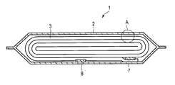
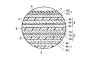
- FIG. 3 is a schematic cross-sectional view of an example of a flat nonaqueous electrolyte battery according to the second embodiment. 4 is an enlarged cross-sectional view of a portion A in FIG.
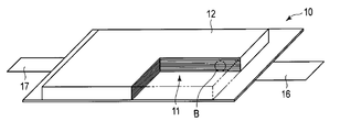
- FIG. 5 is a schematic partially cutaway perspective view of another example of the nonaqueous electrolyte battery according to the second embodiment.
- 6 is an enlarged cross-sectional view of a portion B in FIG.
- It is a general
- FIG. 9 is a schematic perspective view of an example assembled battery that can be included in the battery pack according to the third embodiment.
- an electrode is provided.
- This electrode includes a current collector and an electrode active material-containing layer formed on the current collector.
- the electrode active material-containing layer includes orthorhombic Na-containing niobium titanium composite oxide particles.
- Orthorhombic Akiragata Na-containing niobium titanium composite oxide is represented by the general formula Li 2 + v Na 2-y M1 x Ti 6-yz Nb y M2 z O 14 + ⁇ .
- M1 is at least one selected from the group consisting of Cs, K, Sr, Ba and Ca
- M2 is Zr, Sn, V, Ta, Mo, W, Fe, Co, Mn and At least one selected from the group consisting of Al, 0 ⁇ v ⁇ 4, 0 ⁇ x ⁇ 2, 0 ⁇ y ⁇ 2, 0 ⁇ z ⁇ 3, ⁇ 0.5 ⁇ ⁇ ⁇ 0.5 .
- the electrode active material-containing layer has a porosity of 10% or more and 26% or less obtained by a mercury intrusion method. In the pore diameter distribution obtained by the mercury intrusion method for the electrode active material-containing layer, the strongest peak exists in a region where the pore diameter is smaller than 200 nm.
- the general formula Li 2 + v Na 2-y M1 x Ti 6-yz Nb y M2 z O 14 + orthorhombic Akiragata Na-containing niobium titanium composite oxide represented by ⁇ the lithium at low potential among titanium oxide It is a complex oxide that can be occluded and released.
- the lithium sodium titanium composite oxide represented by the above general formula can exhibit a lithium storage and release potential in the range of 1.2 to 1.4 V, that is, an operating potential.
- a non-aqueous electrolyte battery using orthorhombic Na-containing niobium titanium composite oxide as a negative electrode can exhibit a higher battery voltage than a non-aqueous electrolyte battery using lithium titanate as a negative electrode, and is in a charged state. Can be easily grasped based on the change in potential.
- the inventors have found that the orthorhombic Na-containing niobium titanium composite oxide has a problem that the input / output characteristics are inferior.
- the inventors have found the electrode according to the first embodiment as a result of further research to solve the above problems.
- the orthorhombic Na-containing niobium titanium composite oxide particles sufficiently form a conductive path and exhibit excellent nonaqueous electrolyte impregnation properties. be able to. Therefore, the electrode according to the first embodiment can provide a nonaqueous electrolyte battery that can exhibit excellent input / output characteristics. The reason will be described in detail below.
- the orthorhombic Na-containing niobium titanium composite oxide has a small effect of improving the electronic conductivity due to the occlusion of Li, unlike lithium titanate having a spinel crystal structure. Therefore, in order to form an excellent conductive path in the electrode active material-containing layer, the orthorhombic Na-containing niobium titanium composite oxide particles are preferably in contact with each other. As the contact between the particles contained in the electrode active material-containing layer increases, the porosity of the electrode active material-containing layer decreases. If the porosity is too high, a sufficient conductive path cannot be obtained, and the electrical resistance of the electrode active material-containing layer increases.
- a nonaqueous electrolyte impregnation property of the electrode active material-containing layer is lowered.
- the lower the nonaqueous electrolyte impregnation property the more the Li migration in the electrode active material-containing layer is inhibited. That is, a nonaqueous electrolyte battery using an electrode including an electrode active material-containing layer having a porosity of less than 10% or higher than 26% has high resistance and poor input / output characteristics.
- the electrode active material-containing layer in which the strongest peak exists in the region where the pore diameter is 200 nm or more in the pore diameter distribution obtained by the mercury intrusion method The pore diameter of the pores present in the electrode active material-containing layer with the highest frequency is too large.
- Such an electrode active material-containing layer has large pores between the orthorhombic Na-containing niobium titanium composite oxide particles, and is sufficient between the orthorhombic Na-containing niobium titanium composite oxide particles. Cannot have a conductive path.
- the porosity is preferably 12% or more and 24% or less, and more preferably 15% or more and 20% or less.
- the strongest peak of the pore diameter distribution is preferably in a region where the pore diameter is smaller than 180 nm, and more preferably in a region where the pore diameter is smaller than 150 nm.
- the electrode having an aspect in which the porosity and / or the strongest peak position are within a preferable range can have a more sufficient conductive path between the particles of the orthorhombic Na-containing niobium titanium composite oxide, and is superior to the nonaqueous electrolyte. Can exhibit impregnation properties.
- the porosity is within a range of 10% to 26% and the position of the strongest peak is a region where the diameter is smaller than 200 nm. An improvement in properties cannot be achieved. This point will be proved later in the present specification with a comparative example.
- the electrode according to the first embodiment includes a current collector.
- the current collector is preferably formed from an aluminum foil or an aluminum alloy foil containing elements such as Mg, Ti, Zn, Mn, Fe, Cu and Si.
- the current collector can have, for example, two surfaces facing away from each other.
- the current collector has, for example, a band shape.
- the electrode according to the first embodiment further includes an electrode active material-containing layer formed on the current collector.
- the current collector can carry the electrode active material-containing layer only on one surface thereof, or can carry the electrode active material-containing layer on both surfaces.
- the current collector can also include a portion that does not carry the electrode active material-containing layer on the surface. This part can serve as an electrode tab, for example.
- the electrode according to the first embodiment can include an electrode tab that is separate from the current collector.
- Electrode active material-containing layer as previously indicated, the general formula Li 2 + v Na 2-y M1 x Ti 6-yz Nb y M2 z O 14 + ⁇ orthorhombic Akiragata Na-containing niobium titanium composite represented by Contains oxide particles.
- the orthorhombic Na-containing niobium titanium composite oxide particles can serve as an active material, for example.
- the subscript v varies within the range of 0 ⁇ v ⁇ 4 depending on the state of charge of the orthorhombic Na-containing niobium titanium composite oxide.
- M1 is at least one selected from the group consisting of Cs, K, Sr, Ba and Ca.
- the orthorhombic Na-containing niobium titanium composite oxide can realize more excellent cycle characteristics by containing Cs.
- K the orthorhombic Na-containing niobium titanium composite oxide can realize more excellent cycle characteristics.
- the orthorhombic Na-containing niobium titanium composite oxide can realize more excellent rate characteristics by containing Sr.
- the orthorhombic Na-containing niobium titanium composite oxide can realize better rate characteristics by containing Ba.
- the orthorhombic Na-containing niobium titanium composite oxide can realize more excellent rate characteristics by containing Ca. More preferably, M1 contains at least one of Sr and Ba.
- the subscript x takes a value in the range of 0 ⁇ x ⁇ 2.
- orthorhombic Na-containing niobium titanium composite oxide contains M1 so that the subscript x is 2 or more, it is difficult to obtain a single-phase crystal phase, and the Li diffusibility in the solid is reduced, resulting in low input / output characteristics.
- the subscript x preferably takes a value in the range of 0.05 to 0.2.
- the orthorhombic Na-containing niobium titanium composite oxide having the subscript x within this range can exhibit more excellent rate characteristics.
- the subscript y takes a value in the range of 0 ⁇ y ⁇ 2.
- the value of the subscript y is larger than 0, a higher reversible capacity can be realized.
- the value of the subscript y is 2 or more, it is difficult to obtain a single-phase crystal phase, and further, the Li diffusibility in the solid is lowered and the input / output characteristics are lowered.
- 0.1 ⁇ y ⁇ 0.8 When the value of the subscript y is smaller than 0.1, the resistance reduction effect at high SOC cannot be obtained.
- the subscript y preferably takes a value in the range of 0.1 to 1.
- the orthorhombic Na-containing niobium titanium composite oxide having the value of the subscript y within this range can exhibit better rate characteristics.
- M2 is at least one selected from the group consisting of Zr, Sn, V, Ta, Mo, W, Fe, Co, Mn and Al.
- the orthorhombic Na-containing niobium titanium composite oxide can realize more excellent cycle characteristics by containing Zr.
- the orthorhombic Na-containing niobium titanium composite oxide can realize better rate characteristics by containing Sn. V and Ta can exhibit the same physical and chemical properties as Nb.
- the orthorhombic Na-containing niobium titanium composite oxide can realize more excellent rate characteristics by containing Mo.
- the orthorhombic Na-containing niobium titanium composite oxide can realize more excellent rate characteristics when it contains W.
- the orthorhombic Na-containing niobium titanium composite oxide can realize more excellent cycle characteristics by including Fe.
- the orthorhombic Na-containing niobium titanium composite oxide can realize more excellent cycle characteristics by containing Co.
- the orthorhombic Na-containing niobium titanium composite oxide can realize more excellent cycle characteristics by containing Mn.
- the orthorhombic Na-containing niobium titanium composite oxide can realize better rate characteristics by containing Al.
- M2 contains at least one selected from the group consisting of Al, Zr, Sn and V. In another preferred embodiment, M2 is at least one selected from the group consisting of Sn, V, Ta, Mo, W, Fe, Co, and Mn.
- the subscript z takes a value in the range of 0 ⁇ z ⁇ 3.
- orthorhombic Na-containing niobium titanium composite oxide contains M2 so that the value of the suffix z is 3 or more, it is difficult to obtain a single-phase crystal phase, and the Li diffusivity in the solid is further reduced, resulting in input / output. Characteristics are lowered.
- the subscript z preferably takes a value within the range of 0.1 to 0.3. An orthorhombic Na-containing niobium titanium composite oxide having a subscript z value within this range can exhibit more excellent rate characteristics.
- the subscript ⁇ takes a value in the range of ⁇ 0.5 ⁇ ⁇ ⁇ 0.5.
- the subscript ⁇ preferably takes a value in the range of ⁇ 0.1 ⁇ ⁇ ⁇ 0.1.
- An orthorhombic Na-containing niobium titanium composite oxide having a subscript ⁇ in this range can exhibit better rate characteristics and better cycle characteristics.
- the particles of orthorhombic Na-containing niobium titanium composite oxide may be primary particles or secondary particles as aggregates of primary particles.
- the orthorhombic Na-containing niobium titanium composite oxide particles may be a mixture of primary particles and secondary particles.
- the orthorhombic Na-containing niobium titanium composite oxide particles may have carbon attached to the surface. Carbon may be attached to the surface of the primary particle, or may be attached to the surface of the secondary particle.
- the orthorhombic Na-containing niobium titanium composite oxide particles may include secondary particles formed by agglomeration of primary particles having carbon attached to the surface. Such secondary particles can exhibit excellent conductivity because carbon is present between the primary particles.
- Such an embodiment containing secondary particles is preferable because the electrode active material-containing layer can exhibit a lower resistance.
- the average primary particle diameter of the orthorhombic Na-containing niobium titanium composite oxide particles is preferably 0.5 ⁇ m or more and 3 ⁇ m or less, and more preferably 0.9 ⁇ m or more and 2 ⁇ m or less.
- the average secondary particle diameter of the orthorhombic Na-containing niobium titanium composite oxide particles is preferably 5 ⁇ m or more and 20 ⁇ m or less, and more preferably 8 ⁇ m or more and 12 ⁇ m or less. These preferred particle sizes are those of particles that do not contain carbon.
- the average primary particle size is preferably 0.8 ⁇ m or more and 3 ⁇ m or less, and more preferably 1 ⁇ m or more and 2 ⁇ m or less.
- the average secondary particle diameter is preferably 5 ⁇ m or more and 25 ⁇ m or less, and more preferably 8 ⁇ m or more and 15 ⁇ m or less.
- the average particle size is preferably 3 ⁇ m or more and 10 ⁇ m or less, more preferably 4 ⁇ m or more and 7 ⁇ m or less.
- the pore diameter in an electrode active material content layer can be made small, so that the average primary particle diameter of the particle
- the porosity of an electrode active material content layer can be adjusted by adjusting the particle size distribution of a primary particle and / or a secondary particle. For example, by including particles having an average particle size of about 1 ⁇ m and particles having an average particle size of about 10 ⁇ m in the electrode active material-containing layer, voids formed by particles having a larger particle size are reduced. Particles having a particle size can be filled.
- the porosity of an electrode active material content layer can be reduced.
- the orthorhombic Na-containing niobium titanium composite oxide contained in the electrode active material-containing layer is preferably a mixture of primary particles and secondary particles.
- the electrode active material-containing layer since the electrode active material-containing layer includes small primary particles and large secondary particles, the electrode active material-containing layer can have a smaller porosity, and further, an orthorhombic type Higher contact between the particles of the Na-containing niobium titanium composite oxide can be realized.
- the electrode active material-containing layer may further contain a conductive agent and / or a binder in addition to the orthorhombic Na-containing niobium titanium composite oxide particles.
- the conductive agent can enhance the current collecting performance and can exhibit an action of suppressing contact resistance between the active material and the current collector.
- the conductive agent include carbonaceous materials such as acetylene black, carbon black, graphite, carbon nanofiber, and carbon nanotube. Among these, graphite and carbon nanofiber are preferable. Graphite and carbon nanofibers can easily enter between the particles of orthorhombic Na-containing niobium titanium composite oxide, compared to acetylene black and carbon black, and can further reduce the voids in the electrode active material-containing layer. Further, as the conductive agent, it is more preferable to use carbon material particles having a large aspect ratio.
- the carbon material particle here may be a particle containing a carbon material or a fiber containing a carbon material.
- a preferred aspect ratio is 15 or more, more preferably 50 or more.
- Carbon material particles having a large aspect ratio can impart conductivity in the thickness direction of the electrode active material-containing layer, and can realize higher input / output characteristics.
- the conductive agent one of the above-described carbonaceous materials may be used alone, or a plurality of carbonaceous materials may be used.
- the binder can have an action of binding the active material, the conductive agent, and the current collector.
- the binder include polytetrafluoroethylene (PTFE), polyvinylidene fluoride (PVdF), and fluorine-based rubber, styrene butadiene rubber, an acrylic resin or a copolymer thereof, polyacrylic acid, polyacrylonitrile, and the like. .
- the electrode active material-containing layer can also contain an active material other than particles of orthorhombic Na-containing niobium titanium composite oxide.
- an active material include Li 4 Ti 5 O 12 , TiNb 2 O 7 , TiO 2 (B), Li 2 Na 2 Ti 6 O 14 , and Li 2 SrTi 6 O 14 . It is preferable that particles of the orthorhombic Na-containing niobium titanium composite oxide occupy 70% by mass or more of the active material included in the electrode active material-containing layer, and the electrode active material-containing layer has an orthorhombic Na-containing content. It is preferable that no active material other than the niobium titanium composite oxide particles be included.
- the compounding ratio of the active material, the conductive agent and the binder is 70% by mass to 96% by mass for the active material, 2% by mass to 28% by mass for the negative electrode conductive agent, and 2% by mass to 28% by mass for the binder.
- the active material is more preferably 85% by mass or more and 93% by mass. If the conductive agent is less than 2% by mass, the current collection performance of the electrode active material-containing layer may be reduced, and the large current characteristics of the nonaqueous electrolyte battery may be reduced. On the other hand, when the binder is less than 2% by mass, the binding property between the electrode active material-containing layer and the current collector is lowered, and the cycle characteristics may be lowered. On the other hand, from the viewpoint of increasing the capacity, the conductive agent and the binder are each preferably 28% by mass or less.
- the electrode according to the first embodiment can be manufactured by the following procedure, for example. First, a slurry is prepared by suspending particles of orthorhombic Na-containing niobium titanium composite oxide, and an optional conductive agent and binder in a solvent. Next, this slurry is applied to one surface or both surfaces of the current collector, and the coating film is dried. Next, an electrode active material-containing layer can be obtained by subjecting the dried coating to a press.
- the density of the electrode active material-containing layer is preferably 2.4 g / cm 3 or more and 2.7 g / cm 3 or less, and more preferably 2.5 g / cm 3 or more and 2.6 g / cm 3 or less.
- An electrode in which the density of the electrode active material-containing layer is within a preferable range has more sufficient contact between particles of the orthorhombic Na-containing niobium titanium composite oxide, and therefore the active material-containing layer has better electronic conductivity. Can be shown.
- the space impregnated with the nonaqueous electrolyte can be more sufficiently secured.
- the porosity and pore diameter distribution of the electrode active material-containing layer are affected by, for example, the particle size distribution of the orthorhombic Na-containing niobium titanium composite oxide and the material and aspect ratio of the conductive agent. .
- the porosity and pore diameter distribution of the electrode active material-containing layer are also affected by the press conditions of the dried coating film.
- a roll press apparatus is used for pressing. The distance between the upper and lower rolls is adjusted to obtain the desired porosity and pore diameter distribution. The roll may be heated to about 100 ° C. and pressed. Further, in a single pressing step, the electrode may spring back, and the desired porosity and pore diameter distribution may not be obtained. In that case, you may press several times. That is, the porosity and pore diameter distribution of the electrode active material-containing layer can be controlled by adjusting, for example, a combination of these conditions.
- the electrode according to the first embodiment can be obtained by the method described in each example in the subsequent stage.
- an electrode to be measured is prepared.
- the electrode incorporated in the nonaqueous electrolyte battery is prepared as follows. First, the nonaqueous electrolyte battery is put into a discharged state. By subjecting the battery to constant current discharge at a current of 0.2 C and a battery voltage of 1.5 V in a 25 ° C. environment, the SOC of the battery can be brought into a 0% state, that is, a discharged state. . Next, the discharged nonaqueous electrolyte battery is decomposed in a glove box under an inert atmosphere such as argon. Remove the electrode from the disassembled battery. The extracted electrode is washed with a chain carbonate such as ethyl methyl carbonate. Thereafter, the electrode is dried. The dried electrode is cut into a size of about 10 mm ⁇ 25 mm to obtain a sample.
- the obtained sample is loaded into a measuring device.
- the mercury intrusion method By performing the mercury intrusion method on the charged sample, the pore size distribution and the porosity of the electrode layer can be obtained.
- the analysis principle of the mercury intrusion method is based on the Washburn equation (1).
- D ⁇ 4 ⁇ cos ⁇ / P (1)
- P the applied pressure
- D the pore diameter
- ⁇ the surface tension of mercury (480 dyne ⁇ cm ⁇ 1)
- ⁇ the contact angle between mercury and the pore wall surface. °. Since ⁇ and ⁇ are constants, the relationship between the applied pressure P and the pore diameter D is obtained from the Washburn equation, and the mercury intrusion volume at that time is measured to derive the pore diameter and its volume distribution. Can do.
- the porosity of the electrode layer and the strongest peak position of the pore diameter can be obtained from the pore diameter distribution thus obtained.
- FIG. 1 is a pore diameter distribution for an electrode active material-containing layer of an example electrode according to the first embodiment.
- the strongest peak of the pore diameter was observed at 120 nm. Moreover, the porosity obtained from the measurement results was 22%. As a result of the test, this electrode was able to show excellent input / output characteristics. This is considered to be because the contact between the particles is sufficiently maintained in the electrode active material-containing layer showing the pore diameter distribution as shown in FIG. Further, in this electrode, since the strongest peak of the pore diameter in the pore diameter distribution is 120 nm, the pore diameter is reduced while maintaining the impregnation property of the electrolytic solution, and the electron conduction in the electrode active material containing layer is reduced. This is thought to be because it became possible to increase the sex.
- lithium ions are separated from the active material to be measured.
- the orthorhombic Na-containing niobium titanium composite oxide contains lithium which does not participate in charge / discharge in the structure. Therefore, the “state where lithium ions are released” as used herein means a state where lithium involved in charge / discharge is released.
- the battery active material to be measured is contained in the negative electrode, the battery is completely discharged. However, lithium ions remaining in the active material may exist even when the battery is discharged. Therefore, attention is paid to the analysis of the X-ray diffraction pattern.
- the battery in such a state is disassembled in a glove box filled with argon.
- the electrode containing the active material to be measured is taken out from the decomposed battery.
- the electrode is washed with a suitable solvent.
- a suitable solvent for example, ethyl methyl carbonate may be used. If the cleaning is insufficient, an impurity phase such as lithium carbonate or lithium fluoride may be mixed under the influence of lithium ions remaining in the electrode. In that case, it is preferable to use an airtight container in which the measurement atmosphere can be performed in an inert gas.
- the cross section of the electrode taken out as described above is cut out with an ion milling device.
- the cross section of the cut-out electrode is observed with a scanning electron microscope (SEM). Sampling of the sample should be performed in an inert atmosphere such as argon or nitrogen while avoiding exposure to the air.
- the crystal structure of the compound contained in each particle selected by SEM can be specified by X-ray diffraction (XRD) measurement.
- an X-ray diffraction pattern belonging to the orthorhombic type is obtained by X-ray diffraction measurement. I can confirm that.
- XRD measurement on the electrode can be performed by cutting the electrode to be measured to the same extent as the area of the holder of the wide-angle X-ray diffractometer and directly attaching it to the glass holder for measurement. At this time, XRD is measured in advance according to the type of the metal foil of the electrode current collector, and it is grasped at which position the peak derived from the current collector appears. In addition, the presence or absence of a peak of a mixture such as a conductive agent or a binder is also grasped in advance. When the peak of the current collector and the peak of the active material overlap, it is desirable to measure by peeling the active material from the current collector. This is for separating overlapping peaks when quantitatively measuring the peak intensity.
- the electrode may be physically peeled off, but is easily peeled off when ultrasonic waves are applied in a solvent. By measuring the electrode thus collected, wide-angle X-ray diffraction measurement of the active material can be performed.
- composition of the entire active material contained in the electrode can be measured by the following procedure.
- the electrode containing the active material to be measured is taken out from the non-aqueous electrolyte battery and washed according to the procedure described above.
- the composition of the particles contained in the electrode is specified by the method described above.
- the electrode layer containing the electrode active material can be peeled from the current collector substrate by placing the electrode body in ethyl methyl carbonate placed in a glass beaker and vibrating in an ultrasonic cleaner. Next, vacuum drying is performed to dry the peeled electrode layer. By pulverizing the obtained electrode layer with a mortar or the like, a powder containing an active material to be measured, a conductive aid, a binder and the like is obtained. By dissolving this powder with an acid, a liquid sample containing an active material can be prepared.
- hydrochloric acid nitric acid, sulfuric acid, hydrogen fluoride and the like can be used as the acid.
- ICP emission spectroscopic analysis it is possible to know the concentration of the element in the active material contained in the electrode.
- the composition and crystal structure of the compound contained in the particles are obtained by combining the results of the identification of the composition by SEM and EDX, the identification of the crystal structure by XRD, and the ICP emission spectroscopic analysis. Can be specified.
- Primary particle size is determined from the diameter of the smallest circle corresponding to the primary particle. Specifically, in the SEM image at a magnification of 3000 times, the particle size is measured 10 times, and the average of the diameters of the smallest circles obtained in each is taken as the primary particle size. For the calculation of the average, the maximum value and the minimum value of the particle diameter are not used among 10 measurements.
- the secondary particle size in the same way as the primary particles. That is, the diameter of the smallest circle corresponding to the secondary particle is obtained. Specifically, in the SEM image at a magnification of 3000 times, the particle size is measured 10 times, and the average of the diameters of the smallest circles obtained in each is taken as the secondary particle size. For the calculation of the average, the maximum value and the minimum value of the particle diameter are not used among 10 measurements.
- the lengths of the long axis and short axis of the conductive agent are obtained by measuring the longest part and the shortest part in the conductive agent particles.
- a value obtained by dividing the length of the obtained major axis by the length of the minor axis is defined as an aspect ratio. Specifically, in the SEM image at a magnification of 3000 times, the measurement of the major axis and the minor axis is performed 10 times, and the aspect ratio is calculated from the length of the major axis and the minor axis obtained in each. For the calculation of the average, the maximum value and the minimum value are not used among 10 measurements.
- FIG. 2 is a schematic cross-sectional view of another example electrode according to the first embodiment.
- the electrode 5 shown in FIG. 2 includes a current collector 5a. Although the both ends are not shown in FIG. 2, the current collector 5a has a strip shape. The current collector 5a has two surfaces facing in opposite directions.
- the electrode active material-containing layer 5b is formed on both surfaces of the current collector 5a.
- the electrode according to the first embodiment includes a current collector and an electrode active material-containing layer formed on the current collector.
- the electrode active material-containing layer includes orthorhombic Na-containing niobium titanium composite oxide particles.
- the electrode active material-containing layer has a porosity of 10% or more and 26% or less obtained by a mercury intrusion method. In the pore diameter distribution obtained by the mercury intrusion method for the electrode active material-containing layer, the strongest peak exists in a region where the pore diameter is smaller than 200 nm.
- the orthorhombic Na-containing niobium titanium composite oxide particles can sufficiently form a conductive path, and can exhibit excellent impregnation properties of the nonaqueous electrolyte. Therefore, the electrode according to the first embodiment can provide a nonaqueous electrolyte battery that can exhibit excellent input / output characteristics.
- a nonaqueous electrolyte battery includes the electrode according to the first embodiment as a negative electrode, a positive electrode, and a negative electrode.
- the nonaqueous electrolyte battery according to the second embodiment includes the electrode according to the first embodiment, it can exhibit excellent input / output characteristics.
- the nonaqueous electrolyte battery according to the second embodiment includes a negative electrode, a positive electrode, and a nonaqueous electrolyte.
- the negative electrode is an electrode according to the first embodiment.
- the electrode according to the first embodiment, and the current collector and electrode active material-containing layer included therein are referred to as a negative electrode, and a negative electrode current collector and a negative electrode active material-containing layer, respectively.
- the active material that can be included in the electrode according to the first embodiment is referred to as a negative electrode active material.
- the positive electrode includes a positive electrode current collector and a positive electrode active material-containing layer formed on the positive electrode current collector.
- the positive electrode current collector can have, for example, two surfaces facing away from each other.
- the positive electrode current collector can carry the positive electrode active material-containing layer only on one surface thereof, or can carry the positive electrode active material-containing layer on both surfaces.
- the positive electrode current collector can also include a portion that does not carry the positive electrode active material-containing layer on the surface. This part can serve as a positive electrode tab, for example.
- the positive electrode can include a positive electrode tab separate from the positive electrode current collector.
- the positive electrode active material-containing layer contains a positive electrode active material.
- the positive electrode active material-containing layer can further contain a conductive agent and a binder in addition to the positive electrode active material.
- the positive electrode and the negative electrode can constitute an electrode group.
- the positive electrode active material-containing layer and the negative electrode active material-containing layer can face each other through a separator, for example.
- the electrode group can have various structures.
- the electrode group can have a stacked structure.
- a stack type electrode group can be obtained, for example, by laminating a plurality of positive electrodes and negative electrodes with a separator interposed between a positive electrode active material-containing layer and a negative electrode active material-containing layer.
- the electrode group may have a wound structure.
- the wound electrode group is formed by laminating one separator, one positive electrode, another separator, and one negative electrode in this order. It can be obtained by winding so that the negative electrode is on the outside.
- the nonaqueous electrolyte can be held in a state of being impregnated in, for example, an electrode group.
- the nonaqueous electrolyte battery according to the second embodiment may further include a negative electrode terminal and a positive electrode terminal.
- the negative electrode terminal can function as a conductor for electrons to move between the negative electrode and the external terminal by being partly connected to a part of the negative electrode.
- the negative electrode terminal can be connected to, for example, a negative electrode current collector, particularly a negative electrode tab.
- the positive electrode terminal can function as a conductor for electrons to move between the positive electrode and an external circuit by being electrically connected to a part of the positive electrode.
- the positive electrode terminal can be connected to, for example, a positive electrode current collector, particularly a positive electrode tab.
- the nonaqueous electrolyte battery according to the second embodiment can further include an exterior member.
- the exterior member can accommodate the electrode group and the nonaqueous electrolyte.
- the nonaqueous electrolyte can be impregnated in the electrode group within the exterior member.
- a part of each of the positive electrode terminal and the negative electrode terminal can be extended from the exterior member.
- the positive electrode current collector is preferably an aluminum foil or an aluminum alloy foil containing one or more elements selected from Mg, Ti, Zn, Mn, Fe, Cu, and Si.
- the positive electrode active material includes, for example, manganese dioxide (MnO 2 ) that absorbs lithium, iron oxide, copper oxide, nickel oxide, lithium nickel composite oxide (eg, Li u NiO 2 ), lithium cobalt composite oxide (eg, Li u CoO 2 ), lithium nickel cobalt composite oxide (eg, Li u Ni 1-s Co s O 2 ), lithium manganese cobalt composite oxide (eg, Li u Mn s Co 1-s O 2 ), lithium nickel cobalt-manganese composite oxide (e.g., Li u Ni 1-st Co s Mn t O 2), lithium-nickel-cobalt-aluminum composite oxide (e.g., Li u Ni 1-st Co s Al t O 2), lithium manganese composite oxide objects (e.g., Li u Mn 2 O 4 or Li u MnO 2), lithium phosphates having an olivine structure (e.g., Li u FePO 4 Li u MnPO 4, Li
- a spinel type lithium manganese composite oxide may be used alone, or a plurality of compounds may be used in combination.
- lithium manganese composite oxide Since it is easy to obtain high input / output characteristics and excellent lifetime characteristics, lithium manganese composite oxide, lithium cobalt composite oxide (Li u CoO 2 ), lithium nickel cobalt composite oxide (Li u Ni 1- s Co s O 2), lithium manganese cobalt composite oxide (Li u Mn s Co 1- s O 2), lithium-nickel-cobalt-manganese composite oxide (e.g. Li u Ni 1-st Co s Mn t O 2), or It is preferable to include a lithium phosphorus oxide having an olivine structure (for example, Li u FePO 4 , Li u MnPO 4 , Li u Mn 1-s Fe s PO 4 , Li u CoPO 4 ). In the above, 0 ⁇ u ⁇ 1, 0 ⁇ s ⁇ 1, and 0 ⁇ t ⁇ 1 are preferable.
- the conductive agent that can be included in the positive electrode can enhance the current collecting performance and can have an action of suppressing the contact resistance between the active material and the current collector.
- Examples of the conductive agent include carbonaceous materials such as acetylene black, carbon black, graphite, carbon nanofiber, and carbon nanotube. As the carbonaceous material, one of these may be used alone, or a plurality of carbonaceous materials may be used.
- the binder can have an action of binding the active material, the conductive agent, and the current collector.
- the binder include polytetrafluoroethylene (PTFE), polyvinylidene fluoride (PVdF), and fluorine-based rubber, styrene butadiene rubber, an acrylic resin or a copolymer thereof, polyacrylic acid, polyacrylonitrile, and the like. .
- the total amount of the positive electrode active material, the conductive agent, and the binder in the positive electrode active material-containing layer are 80% by mass to 95% by mass, 3% by mass to 18% by mass, and 2% by mass to 17% by mass, respectively. It is preferable to mix
- the conductive agent can exhibit the above-described effects by adjusting the amount to 3% by mass or more. By making the amount of the conductive agent 18% by mass or less, the decomposition of the nonaqueous electrolyte on the surface of the conductive agent under high temperature storage can be reduced. Sufficient electrode strength can be obtained by setting the binder to an amount of 2% by mass or more. By setting the binder to an amount of 17% by mass or less, the amount of the binder, which is an insulating material in the positive electrode, can be reduced, and the internal resistance can be reduced.
- the positive electrode can be produced, for example, by the following method. First, a positive electrode active material, a conductive agent, and a binder are suspended in a solvent to prepare a slurry. This slurry is applied to one surface or both surfaces of the positive electrode current collector, and the coating film is dried. Subsequently, a positive electrode active material content layer can be obtained by using the dried coating film for a press. Alternatively, the positive electrode active material, the conductive agent, and the binder can be formed into pellets, and these pellets can be arranged on the positive electrode current collector to be used as the positive electrode active material layer.
- Nonaqueous electrolyte for example, a liquid non-aqueous electrolyte or a gel non-aqueous electrolyte can be used.
- the liquid non-aqueous electrolyte can be prepared by dissolving the electrolyte in an organic solvent.
- concentration of the electrolyte is preferably in the range of 0.5 to 2.5 mol / l.
- the gel-like nonaqueous electrolyte is prepared by combining a liquid electrolyte and a polymer material.
- Examples of the electrolyte include lithium perchlorate (LiClO 4 ), lithium hexafluorophosphate (LiPF 6 ), lithium tetrafluoroborate (LiBF 4 ), lithium hexafluoroarsenate (LiAsF 6 ), trifluoromethane Lithium salts such as lithium sulfonate (LiCF 3 SO 3 ) and lithium bistrifluoromethylsulfonylimide [LiN (CF 3 SO 2 ) 2 ] are included.
- the electrolyte one of these electrolytes may be used alone, or two or more kinds of electrolytes may be used in combination.
- the electrolyte preferably contains LiPF 6 .
- organic solvents examples include propylene carbonate (PC), ethylene carbonate (EC), cyclic carbonates such as vinylene carbonate; Carbonates; cyclic ethers such as tetrahydrofuran (THF), 2-methyltetrahydrofuran (2MeTHF), dioxolane (DOX); chain ethers such as dimethoxyethane (DME) and dietoethane (DEE); acetonitrile (AN) and sulfolane ( SL).
- PC propylene carbonate
- EC ethylene carbonate
- cyclic carbonates such as vinylene carbonate
- Carbonates examples include cyclic ethers such as tetrahydrofuran (THF), 2-methyltetrahydrofuran (2MeTHF), dioxolane (DOX); chain ethers such as dimethoxyethane (DME) and dietoethane (DEE); acetonitrile (AN) and sulfolane ( SL).
- Examples of more preferable organic solvents include two or more selected from the group consisting of propylene carbonate (PC), ethylene carbonate (EC), diethyl carbonate (DEC), dimethyl carbonate (DMC), and methyl ethyl carbonate (MEC).
- PC propylene carbonate
- EC ethylene carbonate
- DEC diethyl carbonate
- DMC dimethyl carbonate
- MEC methyl ethyl carbonate
- a mixed solvent in which is mixed By using such a mixed solvent, a nonaqueous electrolyte battery having excellent charge / discharge cycle characteristics can be obtained.
- an additive can also be added to electrolyte solution.
- separator for example, a porous film formed from a material such as polyethylene, polypropylene, polyethylene terephthalate, cellulose, and polyvinylidene fluoride (PVdF), a synthetic resin nonwoven fabric, or the like can be used. Furthermore, the separator which apply
- Exterior material for example, a bag-like container made of a laminate film or a metal container can be used.
- the shape is not particularly limited, and examples include a flat type, a square type, a cylindrical type, a coin type, a button type, a sheet type, and a laminated type.
- a large battery mounted on a two-wheel to four-wheel automobile or the like may be used.
- the laminate film for example, a multilayer film in which a metal layer is sandwiched between resin films can be used. Or the multilayer film which consists of a metal layer and the resin layer which coat
- the metal layer is preferably an aluminum foil or an aluminum alloy foil for weight reduction.
- a polymer material such as polypropylene (PP), polyethylene (PE), nylon, and polyethylene terephthalate (PET) can be used.
- the laminate film can be formed into the shape of an exterior member by sealing by heat sealing.
- the laminate film preferably has a thickness of 0.2 mm or less.
- the metal container can be formed from aluminum or an aluminum alloy.
- the aluminum alloy preferably contains elements such as magnesium, zinc and silicon.
- the content of transition metals such as iron, copper, nickel and chromium is preferably 100 ppm or less. Thereby, it becomes possible to dramatically improve long-term reliability and heat dissipation in a high temperature environment.
- the metal container preferably has a thickness of 0.5 mm or less, and more preferably has a thickness of 0.2 mm or less.
- the positive electrode terminal is formed from a material that is electrically stable and has conductivity, for example, in a range where the potential with respect to the oxidation-reduction potential of lithium is 3.0 V to 4.5 V. It is preferably formed from aluminum or an aluminum alloy containing elements such as Mg, Ti, Zn, Mn, Fe, Cu and Si.
- the positive electrode terminal is preferably formed of the same material as the positive electrode current collector in order to reduce contact resistance with the positive electrode current collector.
- the negative electrode terminal is formed of a material that is electrically stable and has conductivity in a range where the potential with respect to the oxidation-reduction potential of lithium is 0.8 V or more and 3.0 V or less. It is preferably formed from aluminum or an aluminum alloy containing an element such as Mg, Ti, Zn, Mn, Fe, Cu, or Si. The negative electrode terminal is preferably formed from the same material as the negative electrode current collector in order to reduce the contact resistance with the negative electrode current collector.
- FIG. 3 is a schematic cross-sectional view of an example of a flat type nonaqueous electrolyte battery according to the second embodiment.
- 4 is an enlarged cross-sectional view of a portion A in FIG.
- the non-aqueous electrolyte battery 1 shown in FIGS. 3 and 4 includes a flat wound electrode group 3 shown in FIG.
- the flat wound electrode group 3 is accommodated in a bag-shaped exterior member 2 made of a laminate film including a metal layer and two resin films sandwiching the metal layer.
- the flat wound electrode group 3 is formed by winding a laminate of the negative electrode 5, the separator 6, the positive electrode 4, and the separator 6 in this order from the outside in a spiral shape and press-molding.
- the outermost portion of the negative electrode 5 forms a negative electrode active material-containing layer 5b containing a negative electrode active material on one surface on the inner surface side of the negative electrode current collector 5a.
- the negative electrode active material containing layer 5b is formed on both surfaces of the negative electrode current collector 5a.
- positive electrode active material-containing layers 4b are formed on both surfaces of the positive electrode current collector 4a.
- the negative electrode terminal 8 is connected to the negative electrode current collector 5 a in the outermost layer portion of the negative electrode 5, and the positive electrode terminal 7 is the positive electrode of the positive electrode 4 positioned inside. It is connected to the current collector 4a.
- the negative terminal 8 and the positive terminal 7 are extended to the outside from the opening of the bag-shaped exterior member 2.
- the nonaqueous electrolyte battery 1 shown in FIGS. 3 and 4 further includes a nonaqueous electrolyte (not shown).
- the nonaqueous electrolyte is accommodated in the exterior member 2 in a state of being impregnated in the electrode group 3.
- the nonaqueous electrolyte can be injected from, for example, the opening of the bag-shaped exterior member 2. After the nonaqueous electrolyte is injected, the wound electrode group 1 and the nonaqueous electrolyte can be completely sealed by heat-sealing the opening of the bag-shaped exterior member 2 with the negative electrode terminal 8 and the positive electrode terminal 7 interposed therebetween.
- the nonaqueous electrolyte battery according to the second embodiment is not limited to the configuration shown in FIGS. 3 and 4 described above, and can be configured as shown in FIGS. 4 and 5, for example.
- FIG. 5 is a schematic partially cutaway perspective view of another example of the nonaqueous electrolyte battery according to the second embodiment.
- 6 is an enlarged cross-sectional view of a portion B in FIG.
- a nonaqueous electrolyte battery 10 shown in FIGS. 5 and 6 includes a stacked electrode group 11.
- the laminated electrode group 11 is housed in an exterior member 12 made of a laminate film including a metal layer and two resin films sandwiched between the metal layers.
- the stacked electrode group 11 has a structure in which positive electrodes 13 and negative electrodes 14 are alternately stacked with separators 15 interposed therebetween.
- positive electrodes 13 each of which includes a current collector 13 a and a positive electrode active material-containing layer 13 b supported on both surfaces of the current collector 13 a.
- negative electrodes 14 each of which includes a current collector 14a and a negative electrode active material-containing layer 14b supported on both surfaces of the current collector 14a.
- One side of the current collector 14 a of each negative electrode 14 protrudes from the positive electrode 13.
- a portion of the current collector 14 a that protrudes from the positive electrode 13 is electrically connected to the strip-shaped negative electrode terminal 16.
- the tip of the strip-shaped negative electrode terminal 16 is drawn out from the exterior member 12 to the outside.
- the current collector 13a of the positive electrode 13 protrudes from the negative electrode 14 on the side opposite to the protruding side of the current collector 14a.
- a portion of the current collector 13 a that protrudes from the negative electrode 14 is electrically connected to the belt-like positive electrode terminal 17.
- the tip of the strip-like positive electrode terminal 17 is located on the opposite side of the negative electrode terminal 16 and is drawn out from the side of the exterior member 12 to the outside.
- the nonaqueous electrolyte battery according to the second embodiment includes the electrode according to the first embodiment, it can exhibit excellent input / output characteristics.
- a battery pack is provided.
- This battery pack includes the nonaqueous electrolyte battery according to the second embodiment.
- the battery pack according to the third embodiment can also include a plurality of nonaqueous electrolyte batteries.
- the plurality of nonaqueous electrolyte batteries can be electrically connected in series, or can be electrically connected in parallel.
- a plurality of nonaqueous electrolyte batteries can be connected in a combination of series and parallel.
- the battery pack according to the third embodiment can also include five nonaqueous electrolyte batteries according to the second embodiment. These non-aqueous electrolyte batteries can be connected in series. Moreover, the non-aqueous electrolyte battery connected in series can comprise an assembled battery. That is, the battery pack according to the third embodiment can include an assembled battery.
- the battery pack according to the third embodiment can include a plurality of assembled batteries.
- the plurality of assembled batteries can be connected in series, parallel, or a combination of series and parallel.
- the battery pack according to the third embodiment will be described in detail with reference to FIGS.
- the flat battery shown in FIGS. 3 and 4 can be used as the unit cell.
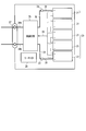
- a plurality of unit cells 21 composed of the flat type non-aqueous electrolyte battery shown in FIGS. 3 and 4 are laminated so that the negative electrode terminal 8 and the positive electrode terminal 7 extending to the outside are aligned in the same direction, and are adhered.
- the assembled battery 23 is configured by fastening with the tape 22.
- the printed wiring board 24 is arranged to face the side surface of the unit cell 21 from which the negative electrode terminal 8 and the positive electrode terminal 7 extend. As shown in FIG. 8, the printed wiring board 24 is mounted with a thermistor 25, a protection circuit 26, and a terminal 27 for energizing external devices. An insulating plate (not shown) is attached to the surface of the protection circuit board 24 facing the assembled battery 23 in order to avoid unnecessary connection with the wiring of the assembled battery 23.
- the positive electrode side lead 28 is connected to the positive electrode terminal 7 located in the lowermost layer of the assembled battery 23, and the tip thereof is inserted into the positive electrode side connector 29 of the printed wiring board 24 and electrically connected thereto.
- the negative electrode side lead 30 is connected to the negative electrode terminal 8 located in the uppermost layer of the assembled battery 23, and the tip thereof is inserted into and electrically connected to the negative electrode side connector 31 of the printed wiring board 24.
- These connectors 29 and 31 are connected to the protection circuit 26 through wirings 32 and 33 formed on the printed wiring board 24.
- the thermistor 25 detects the temperature of the unit cell 21, and the detection signal is transmitted to the protection circuit 26.
- the protection circuit 26 can cut off the plus side wiring 34a and the minus side wiring 34b between the protection circuit 26 and the energization terminal 27 to the external device under a predetermined condition.
- the predetermined condition is, for example, when the temperature detected by the thermistor 25 is equal to or higher than a predetermined temperature.
- the predetermined condition is when the overcharge, overdischarge, overcurrent, etc. of the cell 21 are detected. This detection of overcharge or the like is performed for each individual cell 21 or the entire assembled battery 23.
- the battery voltage may be detected, or the positive electrode potential or the negative electrode potential may be detected.
- a lithium electrode used as a reference electrode is inserted into each unit cell 21.
- a wiring 35 for voltage detection is connected to each single cell 21, and a detection signal is transmitted to the protection circuit 26 through these wirings 35.
- Protective sheets 36 made of rubber or resin are respectively disposed on the three side surfaces of the assembled battery 23 excluding the side surfaces from which the positive electrode terminal 7 and the negative electrode terminal 8 protrude.
- the assembled battery 23 is stored in a storage container 37 together with each protective sheet 36 and the printed wiring board 24. That is, the protective sheet 36 is disposed on each of the inner side surface in the long side direction and the inner side surface in the short side direction of the storage container 37, and the printed wiring board 24 is disposed on the inner side surface on the opposite side in the short side direction.
- the assembled battery 23 is located in a space surrounded by the protective sheet 36 and the printed wiring board 24.
- the lid 38 is attached to the upper surface of the storage container 37.
- a heat shrink tape may be used for fixing the assembled battery 23.
- protective sheets are arranged on both side surfaces of the assembled battery, the heat shrinkable tape is circulated, and then the heat shrinkable tape is heat shrunk to bind the assembled battery.
- FIG. 7 and 8 show the configuration in which the unit cells 21 are connected in series, but in order to increase the battery capacity, they may be connected in parallel.
- the assembled battery packs can be connected in series and / or in parallel.
- the battery pack according to the third embodiment can include the nonaqueous electrolyte battery according to the first embodiment in various forms.
- FIG. 9 is a schematic perspective view of an example assembled battery that can be included in the battery pack according to the third embodiment.
- the assembled battery 23 shown in FIG. 9 includes five unit cells 21 1 to 21 5 .
- Each of the batteries 21 1 to 21 5 is an example non-aqueous electrolyte battery according to the second embodiment.
- Each of the batteries 21 1 to 21 5 includes a metal square-shaped exterior member 2.
- the exterior member 2 accommodates an electrode group similar to the electrode group 3 shown in FIG. 3 and a nonaqueous electrolyte impregnated in the electrode group.
- Cell 21 1 of the positive electrode terminal 7 shown in the left end is connected to the positive electrode side lead 28 for external connection.
- the negative terminal of the battery 21 1 8 is connected via a lead 40 to the positive terminal 7 of the battery 21 2 adjacent to the right of the battery 21 1.
- the negative terminal of the battery 21 2 8 is connected via a lead 40 to the positive terminal 7 of the battery 21 3 adjacent to the right of the battery 21 2.
- the negative terminal of the battery 21 3 8 is connected via a lead 40 to the positive terminal 7 of the battery 21 4 adjacent to the right of the battery 21 3.
- the negative terminal of the battery 21 4 8 is connected via a lead 40 to the positive terminal 7 of the battery 21 5 adjacent the right side of the battery 21 4.
- the negative terminal 8 of the battery 21 5 shown in the right end is connected to the negative lead 30 for external connection. With such connection, the five batteries 21 1 to 21 5 are electrically connected in series.
- An assembled battery constituted by connecting five nonaqueous electrolyte batteries according to the second embodiment in series can exhibit an average operating voltage of 12V to 14V.
- the average operating voltage within this range is about the same as the average operating voltage of a 12V battery pack including a lead storage battery. Therefore, an assembled battery capable of exhibiting such an average operating voltage can assist input / output of the lead storage battery when used in parallel with a 12V system assembled battery including the lead storage battery. Thereby, the charge by the overdischarge and excessive current which cause deterioration of a lead storage battery can be prevented. Therefore, the assembled battery configured by connecting five nonaqueous electrolyte batteries according to the second embodiment in series can exhibit excellent voltage compatibility with an assembled battery including a lead storage battery.
- the battery pack according to the third embodiment includes the nonaqueous electrolyte battery according to the second embodiment, it can exhibit excellent input / output characteristics.
- Example 1 the nonaqueous electrolyte battery of Example 1 was produced by the following procedure.
- a powder of a spinel type lithium manganese composite oxide LiAl 0.1 Mn 1.9 O 4 was prepared as a positive electrode active material.
- This composite oxide, acetylene black as a conductive agent, and polyvinylidene fluoride (PVdF) as a binder are mixed at a mixing ratio of 90% by mass: 5% by mass: 5% by mass with N-methyl as a solvent.
- NMP pyrrolidone
- the prepared slurry was applied to both surfaces of a current collector made of an aluminum foil having a thickness of 15 ⁇ m.
- the coating amount per unit area was 95 g / m 2 .
- the coating film was dried and subjected to pressing.
- a positive electrode having an electrode density (not including the current collector) of 2.7 g / cm 3 was produced.
- orthorhombic Na-containing niobium titanium composite oxide Li 2 Na 1.7 Ti 5.7 Nb 0.3 O 14 powder was prepared by the following procedure.
- the prepared slurry was applied to both surfaces of a current collector made of an aluminum foil having a thickness of 15 ⁇ m.
- the coating film was dried and subjected to pressing. The distance between the rolls of the roll press apparatus was adjusted to produce a negative electrode having an electrode density (not including the current collector) of 2.5 g / cm 3 .
- the positive electrode prepared earlier, one separator, the negative electrode prepared earlier, and another separator were laminated in this order to obtain a laminate.
- This laminate was wound in a spiral. This was heated and pressed at 90 ° C. to produce a flat electrode group having a width of 30 mm and a thickness of 3.0 mm.
- the obtained electrode group was housed in a pack made of a laminate film and vacuum dried at 80 ° C. for 24 hours.
- the laminate film was constituted by forming a polypropylene layer on both sides of an aluminum foil having a thickness of 40 ⁇ m, and the overall thickness was 0.1 mm.
- a liquid nonaqueous electrolyte was injected into the laminate film pack containing the electrode group as described above. Thereafter, the pack was completely sealed by heat sealing.
- a nonaqueous electrolyte battery having the structure shown in FIGS. 3 and 4 described above, having a width of 35 mm, a thickness of 3.2 mm, and a height of 65 mm was manufactured.
- the capacity of this nonaqueous electrolyte battery was 300 mAh.
- Example 2 In Example 2, synthesis was performed by changing the firing temperature of the active material from 900 ° C. to 830 ° C. during the production of the negative electrode, and the average primary particle diameter of the Li 2 Na 1.7 Ti 5.7 Nb 0.3 O 14 powder was 1 ⁇ m.
- a nonaqueous electrolyte battery of Example 2 was produced in the same procedure as in Example 1 except that. Also in the negative electrode density, the negative electrode was produced at 2.5 g / cm 3 in the same manner as in Example 1.
- Example 3 the nonaqueous electrolyte battery of Example 3 was produced in the same procedure as in Example 1 except for the following points.
- Example 3 at the time of producing the negative electrode, a powder of Li 2 Na 1.7 Ti 5.7 Nb 0.3 O 14 was granulated to obtain a secondary particle form.
- the slurry obtained as described above was sprayed by a two-fluid nozzle method and granulated. At this time, the drying temperature was 120 ° C.
- the obtained secondary particles were heat-treated at 600 ° C. for 1 hour.
- the average secondary particle diameter of the negative electrode active material thus obtained was 15 ⁇ m.
- the electrode density of the negative electrode (not including the current collector) was 2.5 g / cm 3 as in Example 1.
- Example 4 the nonaqueous electrolyte battery of Example 4 was produced in the same procedure as in Example 1 except for the following points.
- Example 4 during the production of the negative electrode, a powder of Li 2 Na 1.7 Ti 5.7 Nb 0.3 O 14 was granulated into a secondary particle form.
- the granulation method was the same as that of Example 3 except that 0.5% by mass of carboxymethyl cellulose was added to the mass of primary particles of Li 2 Na 1.7 Ti 5.7 Nb 0.3 O 14 .
- the average secondary particle diameter of the obtained active material was 8 ⁇ m.
- the electrode density of the negative electrode (not including the current collector) was 2.5 g / cm 3 as in Example 1.
- Example 5 the nonaqueous electrolyte battery of Example 5 was produced in the same procedure as in Example 1 except for the following points.
- Example 5 during the production of the negative electrode, a powder of Li 2 Na 1.7 Ti 5.7 Nb 0.3 O 14 was granulated into a secondary particle form.
- the granulation method was the same as Example 3 except that 1% by mass of carboxymethyl cellulose was added to the mass of primary particles of Li 2 Na 1.7 Ti 5.7 Nb 0.3 O 14 .
- the average secondary particle diameter of the obtained active material was 18 ⁇ m.
- the electrode density of the negative electrode (not including the current collector) was 2.5 g / cm 3 as in Example 1.
- Example 6 the nonaqueous electrolyte battery of Example 6 was produced in the same procedure as in Example 1 except for the following points.
- Example 6 during the production of the negative electrode, a powder of Li 2 Na 1.7 Ti 5.7 Nb 0.3 O 14 was granulated into a secondary particle form.
- the granulation method was the same as that of Example 3 except that 0.3% by mass of carboxymethyl cellulose was added to the mass of primary particles of Li 2 Na 1.7 Ti 5.7 Nb 0.3 O 14 .
- the average secondary particle diameter of the obtained active material was 5 ⁇ m.
- Example 6 when dispersing the slurry using a rotation and revolution mixer, glass beads having a diameter of 2 mm were placed in a container at 33% of the slurry volume to prepare a slurry. Furthermore, the distance between the rolls of the roll press apparatus was adjusted to be narrower than that of Example 1, so that the electrode density of the negative electrode (excluding the current collector) was 2.6 g / cm 3 .
- Example 7 In Example 7, the same procedure as in Example 1 was used, except that 2.5% by mass of acetylene black and 2.5% by mass of graphite were used instead of 5% by mass of acetylene black as a conductive agent when producing the negative electrode. Thus, a nonaqueous electrolyte battery of Example 7 was produced.
- the electrode density of the negative electrode (not including the current collector) was 2.5 g / cm 3 as in Example 1.
- Example 8 In Example 8, 2.5% by mass of vapor-grown carbon fiber having an acetylene black of 2.5% by mass and an aspect ratio of 50 was used in place of acetylene black of 5% by mass as a conductive agent in producing the negative electrode.
- a nonaqueous electrolyte battery of Example 8 was produced in the same procedure as in Example 1 except that.
- the electrode density of the negative electrode (not including the current collector) was 2.5 g / cm 3 as in Example 1.
- Example 9 In Example 9, when producing the negative electrode, instead of 5% by mass of acetylene black as a conductive agent, 2.5% by mass of graphite and 2.5% by mass of vapor grown carbon fiber having an aspect ratio of 30 were used. A nonaqueous electrolyte battery of Example 9 was produced in the same procedure as in Example 1 except for the above. The electrode density of the negative electrode (not including the current collector) was 2.5 g / cm 3 as in Example 1.
- Example 10 In Example 10, in the production of the negative electrode, instead of 5% by mass of acetylene black as a conductive agent, 2.5% by mass of graphite and 2.5% by mass of vapor-grown carbon fiber having an aspect ratio of 18 were used. A nonaqueous electrolyte battery of Example 10 was produced in the same procedure as in Example 1 except for the above. The electrode density of the negative electrode (not including the current collector) was 2.5 g / cm 3 as in Example 1.
- Example 11 In Example 11, at the time of producing the negative electrode, instead of 5% by mass of acetylene black as the conductive agent, 2.5% by mass of graphite and 2.5% by mass of vapor-grown carbon fiber having an aspect ratio of 18 were used. A nonaqueous electrolyte battery of Example 11 was produced in the same procedure as in Example 1 except for the above. The distance between the rolls of the roll press apparatus was adjusted to be wider than that of Example 1, and the electrode density of the negative electrode (not including the current collector) was 2.35 g / cm 3 .
- Example 12 the non-aqueous electrolyte battery of Example 12 was prepared in the same manner as in Example 1 except that 5% by mass of graphite was used instead of 5% by mass of acetylene black as a conductive agent when producing the negative electrode.
- the distance between the rolls of the roll press apparatus was adjusted to be narrower than that of Example 1, and the electrode density of the negative electrode (not including the current collector) was 2.65 g / cm 3 .
- Example 13 the nonaqueous electrolyte battery of Example 13 was produced in the same procedure as in Example 1 except that the negative electrode active material was changed.
- a powder of orthorhombic Na-containing niobium titanium composite oxide Li 2 Na 1.9 Ti 5.9 Nb 0.1 O 14 was used as the negative electrode active material.
- This powder was orthorhombic used in Example 1 except that the raw materials were mixed so that the molar ratio of Li: Na: Ti: Nb in the mixture was 2: 1.9: 5.9: 0.1. It was synthesized in the same manner as the procedure for synthesizing the powder of type Na-containing niobium titanium composite oxide.
- the electrode density of the negative electrode (not including the current collector) was 2.5 g / cm 3 as in Example 1.
- Example 14 the nonaqueous electrolyte battery of Example 14 was produced in the same procedure as in Example 1 except that the negative electrode active material was changed.
- an orthorhombic Na-containing niobium titanium composite oxide Li 2.1 Na 1.8 Ti 5.9 Nb 0.1 O 14 powder was used as the negative electrode active material.
- This powder was the same as that used in Example 1 except that the raw materials were mixed so that the molar ratio of Li: Na: Ti: Nb in the mixture was 2.1: 1.8: 5.9: 0.1.
- Synthesis was performed in the same manner as the procedure for synthesizing powder of the tetragonal Na-containing niobium titanium composite oxide.
- the electrode density of the negative electrode (not including the current collector) was 2.5 g / cm 3 as in Example 1.
- Example 15 the nonaqueous electrolyte battery of Example 15 was produced in the same procedure as in Example 1 except that the negative electrode active material was changed.
- orthorhombic Na-containing niobium titanium composite oxide Li 2 Na 1.5 Ti 5.5 Nb 0.5 O 14 powder was used as the negative electrode active material.
- This powder was orthorhombic used in Example 1 except that the raw materials were mixed so that the molar ratio of Li: Na: Ti: Nb in the mixture was 2: 1.5: 5.5: 0.5.
- the electrode density of the negative electrode (not including the current collector) was 2.5 g / cm 3 as in Example 1.
- Example 16 the nonaqueous electrolyte battery of Example 16 was produced in the same procedure as in Example 1 except that the negative electrode active material was changed.
- orthorhombic Na-containing niobium titanium composite oxide Li 2.2 Na 1.3 Ti 5.5 Nb 0.5 O 14 powder was used as the negative electrode active material.
- This powder is the same as that used in Example 1 except that the raw materials were mixed so that the molar ratio of Li: Na: Ti: Nb in the mixture was 2.2: 1.3: 5.5: 0.5.
- Synthesis was performed in the same manner as the procedure for synthesizing powder of the tetragonal Na-containing niobium titanium composite oxide.
- the electrode density of the negative electrode (not including the current collector) was 2.5 g / cm 3 as in Example 1.
- Example 17 the nonaqueous electrolyte battery of Example 17 was produced in the same procedure as in Example 1 except that the negative electrode active material was changed.
- a powder of orthorhombic Na-containing niobium titanium composite oxide Li 2 Na 1.2 Ti 5.2 Nb 0.8 O 14 was used as the negative electrode active material.
- This powder was orthorhombic used in Example 1 except that the raw materials were mixed so that the molar ratio of Li: Na: Ti: Nb in the mixture was 2: 1.2: 5.2: 0.8. It was synthesized in the same manner as the procedure for synthesizing the powder of type Na-containing niobium titanium composite oxide.
- the electrode density of the negative electrode (not including the current collector) was 2.5 g / cm 3 as in Example 1.
- Example 18 the nonaqueous electrolyte battery of Example 18 was produced in the same procedure as in Example 1 except that the negative electrode active material was changed.
- a powder of orthorhombic Na-containing niobium titanium composite oxide Li 2 NaSr 0.5 Ti 5.9 Nb 0.1 O 14 was used as the negative electrode active material.
- a powder of strontium nitrate Sr (NO 3 ) 2 was further used as a raw material, and the molar ratio of Li: Na: Sr: Ti: Nb in the mixture of the raw material was 2: 1: 0.5: 5.
- Example 9 The synthesis was performed in the same manner as the synthesis procedure of the orthorhombic Na-containing niobium titanium composite oxide powder used in Example 1 except that the mixture was mixed to 0.1.
- the electrode density of the negative electrode (not including the current collector) was 2.5 g / cm 3 as in Example 1.
- Example 19 a nonaqueous electrolyte battery of Example 19 was produced in the same procedure as in Example 1 except that the negative electrode active material was changed.
- an orthorhombic Na-containing niobium titanium composite oxide Li 2 Na 1.5 Sr 0.2 Ti 5.9 Nb 0.1 O 14 powder was used as the negative electrode active material.
- This powder was prepared in Example 1 except that the raw materials were mixed so that the molar ratio of Li: Na: Sr: Ti: Nb in the mixture was 2: 1.5: 0.2: 5.9: 0.1.
- the orthorhombic Na-containing niobium titanium composite oxide powder used in the above was synthesized in the same manner as described above.
- the electrode density of the negative electrode (not including the current collector) was 2.5 g / cm 3 as in Example 1.
- Example 20 the nonaqueous electrolyte battery of Example 20 was produced in the same procedure as in Example 1 except that the negative electrode active material was changed.
- a powder of orthorhombic Na-containing niobium titanium composite oxide Li 2 Na 1.5 Mg 0.2 Ti 5.9 Nb 0.1 O 14 was used as the negative electrode active material.
- This powder was obtained by further using magnesium acetate Mg (CH 3 COO) 2 powder as a raw material, and the molar ratio of Li: Na: Mg: Ti: Nb of the raw material mixture was 2: 1.5: 0.2.
- Example 2 Was synthesized in the same manner as the procedure for synthesizing the orthorhombic Na-containing niobium titanium composite oxide powder used in Example 1, except that the mixture was mixed to 5.9: 0.1.
- the electrode density of the negative electrode (not including the current collector) was 2.5 g / cm 3 as in Example 1.
- Example 21 the nonaqueous electrolyte battery of Example 21 was produced in the same procedure as in Example 1 except that the negative electrode active material was changed.
- Example 21 a powder of orthorhombic Na-containing niobium titanium composite oxide Li 2 Na 1.5 Ba 0.2 Ti 5.9 Nb 0.1 O 14 was used as the negative electrode active material.
- This powder was obtained by further using a powder of barium carbonate BaCO 3 as a raw material, and the molar ratio of Li: Na: Ba: Ti: Nb in the mixture of the raw materials was 2: 1.5: 0.2: 5.9: It was synthesized in the same manner as the procedure for synthesizing the orthorhombic Na-containing niobium titanium composite oxide powder used in Example 1, except that the mixture was mixed to 0.1.
- the electrode density of the negative electrode (not including the current collector) was 2.5 g / cm 3 as in Example 1.
- Example 22 a nonaqueous electrolyte battery of Example 22 was produced in the same procedure as in Example 1 except that the negative electrode active material was changed.
- a powder of orthorhombic Na-containing niobium titanium composite oxide Li 2 Na 1.5 Ba 0.2 Ti 5.5 Nb 0.5 O 14 was used as the negative electrode active material.
- This powder was prepared in Example 22 except that the raw materials were mixed so that the molar ratio of Li: Na: Ba: Ti: Nb in the mixture was 2: 1.5: 0.2: 5.5: 0.5.
- the orthorhombic Na-containing niobium titanium composite oxide powder used in the above was synthesized in the same manner as described above.
- the electrode density of the negative electrode (not including the current collector) was 2.5 g / cm 3 as in Example 1.
- Example 23 the nonaqueous electrolyte battery of Example 23 was produced in the same procedure as in Example 1 except that the negative electrode active material was changed.
- powder of orthorhombic Na-containing niobium titanium composite oxide Li 2 Na 1.9 Ti 5.7 Nb 0.1 Al 0.2 O 14 was used as the negative electrode active material.
- This powder further used aluminum oxide Al 2 O 3 powder as a raw material, and the molar ratio of Li: Na: Ti: Nb: Al in the mixture of the raw materials was 2: 1.9: 5.7: 0.
- the electrode density of the negative electrode (not including the current collector) was 2.5 g / cm 3 as in Example 1.
- Example 24 the nonaqueous electrolyte battery of Example 24 was produced in the same procedure as in Example 1 except that the negative electrode active material was changed.
- powder of orthorhombic Na-containing niobium titanium composite oxide Li 2 Na 1.9 Ti 5.8 Nb 0.1 Zr 0.1 O 14 was used as the negative electrode active material.
- This powder was obtained by further using a powder of zirconium oxide ZrO 2 as a raw material, and the molar ratio of Li: Na: Ti: Nb: Zr in the mixture of the raw materials was 2: 1.9: 5.8: 0.1: It was synthesized in the same manner as the procedure for synthesizing the orthorhombic Na-containing niobium titanium composite oxide powder used in Example 1, except that the mixture was mixed to 0.1.
- the electrode density of the negative electrode (not including the current collector) was 2.5 g / cm 3 as in Example 1.
- Example 25 a nonaqueous electrolyte battery of Example 25 was produced in the same procedure as in Example 1 except that the negative electrode active material was changed.
- Example 25 a powder of orthorhombic Na-containing niobium titanium composite oxide Li 2 Na 1.9 Ti 5.8 Nb 0.1 Sn 0.1 O 14 was used as the negative electrode active material.
- This powder was obtained by further using a tin oxide SnO 2 powder as a raw material, and a molar ratio of Li: Na: Ti: Nb: Sn in the mixture of the raw materials was 2: 1.9: 5.8: 0.1: It was synthesized in the same manner as the procedure for synthesizing the orthorhombic Na-containing niobium titanium composite oxide powder used in Example 1, except that the mixture was mixed to 0.1.
- the electrode density of the negative electrode (not including the current collector) was 2.5 g / cm 3 as in Example 1.
- Example 26 the nonaqueous electrolyte battery of Example 26 was produced in the same procedure as in Example 1 except that the negative electrode active material was changed.
- a powder of orthorhombic Na-containing niobium titanium composite oxide Li 2.1 Na 1.9 Ti 5.8 Nb 0.1 Ta 0.1 O 14 was used as the negative electrode active material.
- a powder of tantalum (V) Ta 2 O 5 was further used as a raw material, and the molar ratio of Li: Na: Ti: Nb: Ta in the raw material mixture was 2.1: 1.9: 5.
- Example 27 the nonaqueous electrolyte battery of Example 27 was produced in the same procedure as in Example 1 except that the negative electrode active material was changed.
- a powder of orthorhombic Na-containing niobium titanium composite oxide Li 2.1 Na 1.9 Ti 5.8 Nb 0.1 V 0.1 O 14 was used as the negative electrode active material.
- vanadium (V) V 2 O 5 powder was further used as a raw material, and the molar ratio of Li: Na: Ti: Nb: V of the raw material mixture was 2.1: 1.9: 5.
- Example 28 the nonaqueous electrolyte battery of Example 28 was produced in the same procedure as in Example 1 except that the negative electrode active material was changed.
- an orthorhombic Na-containing niobium titanium composite oxide Li 2 Na 1.9 Ti 5.8 Nb 0.1 Fe 0.1 O 14 powder was used as the negative electrode active material.
- iron (III) Fe 2 O 3 powder was further used as a raw material, and the molar ratio of Li: Na: Ti: Nb: Fe in the mixture of the raw material was 2: 1.9: 5.8.
- the electrode density of the negative electrode (not including the current collector) was 2.5 g / cm 3 as in Example 1.
- Example 29 In Example 29, the nonaqueous electrolyte battery of Example 29 was produced in the same procedure as in Example 1 except that the negative electrode active material was changed.
- powder of orthorhombic Na-containing niobium titanium composite oxide Li 2 Na 1.9 Ti 5.8 Nb 0.1 Co 0.1 O 14 was used as the negative electrode active material.
- a powder of cobalt oxide Co 3 O 4 was further used as a raw material, and the molar ratio of Li: Na: Ti: Nb: Co in the raw material mixture was 2: 1.9: 5.8: 0.
- Example 2 It was synthesized in the same manner as the procedure for synthesizing the orthorhombic Na-containing niobium titanium composite oxide powder used in Example 1, except that the mixture was mixed so as to be 1: 0.1.
- the electrode density of the negative electrode (not including the current collector) was 2.5 g / cm 3 as in Example 1.
- Example 30 the nonaqueous electrolyte battery of Example 30 was produced in the same procedure as in Example 1 except that the negative electrode active material was changed.
- a powder of orthorhombic Na-containing niobium titanium composite oxide Li 2 Na 1.9 Ti 5.8 Nb 0.1 Mn 0.1 O 14 was used as the negative electrode active material.
- This powder further used manganese oxide Mn 3 O 4 powder as a raw material, and the molar ratio of Li: Na: Ti: Nb: Mn in the mixture of the raw materials was 2: 1.9: 5.8: 0.
- Example 2 It was synthesized in the same manner as the procedure for synthesizing the orthorhombic Na-containing niobium titanium composite oxide powder used in Example 1, except that the mixture was mixed so as to be 1: 0.1.
- the electrode density of the negative electrode (not including the current collector) was 2.5 g / cm 3 as in Example 1.
- Example 31 the nonaqueous electrolyte battery of Example 31 was produced in the same procedure as in Example 1 except that the negative electrode active material was changed.
- Example 31 a powder of orthorhombic Na-containing niobium titanium composite oxide Li 2 Na 1.9 Ti 5.8 Nb 0.1 Mo 0.1 O 14 was used as the negative electrode active material.
- This powder was obtained by further using a molybdenum oxide MoO 3 powder as a raw material, and a molar ratio of Li: Na: Ti: Nb: Mo in the mixture of the raw materials was 2: 1.9: 5.8: 0.1: It was synthesized in the same manner as the procedure for synthesizing the orthorhombic Na-containing niobium titanium composite oxide powder used in Example 1, except that the mixture was mixed to 0.1.
- the electrode density of the negative electrode (not including the current collector) was 2.5 g / cm 3 as in Example 1.
- Example 32 In Example 32, the nonaqueous electrolyte battery of Example 32 was produced in the same procedure as in Example 1 except that the positive electrode was produced in the following procedure.
- Example 32 lithium nickel cobalt manganese composite oxide LiNi 0.33 Co 0.33 Mn 0.33 O 2 was used as the positive electrode active material.
- This composite oxide, acetylene black as a conductive agent, and polyvinylidene fluoride (PVdF) as a binder are mixed at a mixing ratio of 90% by mass: 5% by mass: 5% by mass with N-methyl as a solvent. Poured into pyrrolidone (NMP) and mixed. Next, the mixture thus obtained was dispersed using a rotation and revolution mixer to prepare a slurry.
- PVdF polyvinylidene fluoride
- the prepared slurry was applied to both surfaces of a current collector made of an aluminum foil having a thickness of 15 ⁇ m.
- the coating amount per unit area was 91 g / m 2 .
- the coating film was dried and subjected to pressing.
- a positive electrode having an electrode density (not including the current collector) of 3.0 g / cm 3 was produced.
- Example 33 In Example 33, the nonaqueous electrolyte battery of Example 33 was produced in the same procedure as in Example 1 except that the positive electrode was produced in the following procedure.
- lithium cobaltate LiCoO 2 was used as the positive electrode active material.
- This composite oxide, acetylene black as a conductive agent, and polyvinylidene fluoride (PVdF) as a binder are mixed at a mixing ratio of 90% by mass: 5% by mass: 5% by mass with N-methyl as a solvent. Poured into pyrrolidone (NMP) and mixed. Next, the mixture thus obtained was dispersed using a rotation and revolution mixer to prepare a slurry.
- PVdF polyvinylidene fluoride
- the prepared slurry was applied to both surfaces of a current collector made of an aluminum foil having a thickness of 15 ⁇ m.
- the coating amount per unit area was 91 g / m 2 .
- the coating film was dried and subjected to pressing.
- a positive electrode having an electrode density (not including the current collector) of 3.0 g / cm 3 was produced.
- Example 34 In Example 34, the nonaqueous electrolyte battery of Example 34 was produced in the same procedure as in Example 1 except that the positive electrode was produced in the following procedure.
- lithium nickel cobalt manganese composite oxide LiNi 0.5 Co 0.2 Mn 0.3 O 2 was used as the positive electrode active material.
- This composite oxide, acetylene black as a conductive agent, and polyvinylidene fluoride (PVdF) as a binder are mixed at a mixing ratio of 90% by mass: 5% by mass: 5% by mass with N-methyl as a solvent. Poured into pyrrolidone (NMP) and mixed. Next, the mixture thus obtained was dispersed using a rotation and revolution mixer to prepare a slurry.
- PVdF polyvinylidene fluoride
- the prepared slurry was applied to both surfaces of a current collector made of an aluminum foil having a thickness of 15 ⁇ m.
- the coating amount per unit area was 91 g / m 2 .
- the coating film was dried and subjected to pressing.
- a positive electrode having an electrode density (not including the current collector) of 3.0 g / cm 3 was produced.
- Example 35 the nonaqueous electrolyte battery of Example 35 was produced in the same procedure as in Example 1 except that the positive electrode was produced in the following procedure.
- lithium nickel cobalt manganese composite oxide LiNi 0.6 Co 0.2 Mn 0.2 O 2 was used as the positive electrode active material.
- This composite oxide, acetylene black as a conductive agent, and polyvinylidene fluoride (PVdF) as a binder are mixed at a mixing ratio of 90% by mass: 5% by mass: 5% by mass with N-methyl as a solvent. Poured into pyrrolidone (NMP) and mixed. Next, the mixture thus obtained was dispersed using a rotation and revolution mixer to prepare a slurry.
- NMP pyrrolidone
- the prepared slurry was applied to both surfaces of a current collector made of an aluminum foil having a thickness of 15 ⁇ m.
- the coating amount per unit area was 91 g / m 2 .
- the coating film was dried and subjected to pressing.
- a positive electrode having an electrode density (not including the current collector) of 3.0 g / cm 3 was produced.
- Example 36 In Example 36, the nonaqueous electrolyte battery of Example 36 was produced in the same procedure as in Example 1 except that the positive electrode was produced in the following procedure.
- Example 36 lithium nickel cobalt manganese composite oxide LiNi 0.8 Co 0.1 Mn 0.1 O 2 was used as the positive electrode active material.
- This composite oxide, acetylene black as a conductive agent, and polyvinylidene fluoride (PVdF) as a binder are mixed at a mixing ratio of 90% by mass: 5% by mass: 5% by mass with N-methyl as a solvent. Poured into pyrrolidone (NMP) and mixed. Next, the mixture thus obtained was dispersed using a rotation and revolution mixer to prepare a slurry.
- PVdF polyvinylidene fluoride
- the prepared slurry was applied to both surfaces of a current collector made of an aluminum foil having a thickness of 15 ⁇ m.
- the coating amount per unit area was 91 g / m 2 .
- the coating film was dried and subjected to pressing.
- a positive electrode having an electrode density (not including the current collector) of 3.0 g / cm 3 was produced.
- Example 37 In Example 37, the nonaqueous electrolyte battery of Example 37 was produced in the same procedure as in Example 1 except that the positive electrode was produced in the following procedure.
- Example 37 a lithium phosphorous oxide LiMn 0.85 Fe 0.1 Mg 0.05 PO 4 having an olivine structure was used as the positive electrode active material.
- This composite oxide, acetylene black as a conductive agent, and polyvinylidene fluoride (PVdF) as a binder are mixed at a mixing ratio of 90% by mass: 5% by mass: 5% by mass with N-methyl as a solvent. Poured into pyrrolidone (NMP) and mixed. Next, the mixture thus obtained was dispersed using a rotation and revolution mixer to prepare a slurry.
- PVdF polyvinylidene fluoride
- the prepared slurry was applied to both surfaces of a current collector made of an aluminum foil having a thickness of 15 ⁇ m.
- the coating amount per unit area was 91 g / m 2 .
- the coating film was dried and subjected to pressing.
- a positive electrode having an electrode density (not including the current collector) of 2.0 g / cm 3 was produced.
- Example 38 In Example 38, the nonaqueous electrolyte battery of Example 38 was produced in the same procedure as in Example 1 except that the positive electrode was produced in the following procedure.
- Example 38 a mixture of lithium nickel cobalt manganese composite oxide LiNi 0.33 Co 0.33 Mn 0.33 O 2 and lithium cobalt oxide LiCoO 2 was used as the positive electrode active material. 72% by mass: 18% by mass: 5% by mass of LiNi 0.33 Co 0.33 Mn 0.33 O 2 powder, LiCoO 2 powder, acetylene black as a conductive agent, and polyvinylidene fluoride (PVdF) as a binder. The mixture was introduced into N-methylpyrrolidone (NMP) as a solvent at a mixing ratio of%: 5% by mass and mixed. Next, the mixture thus obtained was dispersed using a rotation and revolution mixer to prepare a slurry.
- NMP N-methylpyrrolidone
- the prepared slurry was applied to both surfaces of a current collector made of an aluminum foil having a thickness of 15 ⁇ m.
- the coating amount per unit area was 91 g / m 2 .
- the coating film was dried and subjected to pressing.
- a positive electrode having an electrode density (not including the current collector) of 3.0 g / cm 3 was produced.
- Example 39 a nonaqueous electrolyte battery of Example 39 was produced in the same procedure as in Example 1 except that the positive electrode was produced in the following procedure.
- Example 39 a mixture of lithium nickel cobalt manganese composite oxide LiNi 0.33 Co 0.33 Mn 0.33 O 2 and lithium cobalt oxide LiCoO 2 was used as the positive electrode active material.
- LiNi 0.33 Co 0.33 Mn 0.33 O 2 powder, LiCoO 2 powder, acetylene black as a conductive agent, and polyvinylidene fluoride (PVdF) as a binder are 45% by mass: 45% by mass: 5% by mass.
- the mixture was introduced into N-methylpyrrolidone (NMP) as a solvent at a mixing ratio of%: 5% by mass and mixed. Next, the mixture thus obtained was dispersed using a rotation and revolution mixer to prepare a slurry.
- NMP N-methylpyrrolidone
- the prepared slurry was applied to both surfaces of a current collector made of an aluminum foil having a thickness of 15 ⁇ m.
- the coating amount per unit area was 91 g / m 2 .
- the coating film was dried and subjected to pressing.
- a positive electrode having an electrode density (not including the current collector) of 3.0 g / cm 3 was produced.
- Example 40 In Example 40, the nonaqueous electrolyte battery of Example 40 was produced in the same procedure as in Example 1 except that the positive electrode was produced in the following procedure.
- Example 40 as the positive electrode active material, a mixture of spinel type lithium manganese composite oxide LiAl 0.1 Mn 1.9 O 4 and lithium nickel cobalt manganese composite oxide LiNi 0.33 Co 0.33 Mn 0.33 O 2 was used. 72% by mass: 18% by mass of LiAl 0.1 Mn 1.9 O 4 powder, LiNi 0.33 Co 0.33 Mn 0.33 O 2 powder, acetylene black as a conductive agent, and polyvinylidene fluoride (PVdF) as a binder
- NMP N-methylpyrrolidone
- the mixture thus obtained was dispersed using a rotation and revolution mixer to prepare a slurry.
- the prepared slurry was applied to both surfaces of a current collector made of an aluminum foil having a thickness of 15 ⁇ m.
- the coating amount per unit area was 91 g / m 2 .
- the coating film was dried and subjected to pressing.
- a positive electrode having an electrode density (not including the current collector) of 2.8 g / cm 3 was produced.
- Example 41 In Example 41, the nonaqueous electrolyte battery of Example 41 was produced in the same procedure as in Example 1 except that the positive electrode was produced in the following procedure.
- Example 41 as the positive electrode active material, a mixture of spinel type lithium manganese composite oxide LiAl 0.1 Mn 1.9 O 4 and lithium nickel cobalt manganese composite oxide LiNi 0.33 Co 0.33 Mn 0.33 O 2 was used. 45% by mass: 45% by mass of LiAl 0.1 Mn 1.9 O 4 powder, LiNi 0.33 Co 0.33 Mn 0.33 O 2 powder, acetylene black as a conductive agent, and polyvinylidene fluoride (PVdF) as a binder
- NMP N-methylpyrrolidone
- the mixture thus obtained was dispersed using a rotation and revolution mixer to prepare a slurry.
- the prepared slurry was applied to both surfaces of a current collector made of an aluminum foil having a thickness of 15 ⁇ m.
- the coating amount per unit area was 91 g / m 2 .
- the coating film was dried and subjected to pressing.
- a positive electrode having an electrode density (not including the current collector) of 2.8 g / cm 3 was produced.
- Example 42 In Example 42, the nonaqueous electrolyte battery of Example 42 was produced in the same procedure as in Example 1 except that the positive electrode was produced in the following procedure.
- Example 42 a mixture of spinel type lithium manganese oxide LiAl 0.1 Mn 1.9 O 4 and lithium cobaltate LiCoO 2 was used as the positive electrode active material. 72% by mass: 18% by mass: 5% by mass of LiAl 0.1 Mn 1.9 O 4 powder, LiCoO 2 powder, acetylene black as a conductive agent, and polyvinylidene fluoride (PVdF) as a binder. The mixture was added to N-methylpyrrolidone (NMP) as a solvent at a mixing ratio of 5% by mass and mixed. Next, the mixture thus obtained was dispersed using a rotation and revolution mixer to prepare a slurry.
- NMP N-methylpyrrolidone
- the prepared slurry was applied to both surfaces of a current collector made of an aluminum foil having a thickness of 15 ⁇ m.
- the coating amount per unit area was 91 g / m 2 .
- the coating film was dried and subjected to pressing.
- a positive electrode having an electrode density (not including the current collector) of 2.8 g / cm 3 was produced.
- Example 43 In Example 43, the nonaqueous electrolyte battery of Example 43 was produced in the same procedure as in Example 1 except that the positive electrode was produced in the following procedure.
- Example 43 as the positive electrode active material, a mixture of a lithium phosphorous oxide LiMn 0.85 Fe 0.1 Mg 0.05 PO 4 having an olivine structure and a spinel type lithium manganese composite oxide LiAl 0.1 Mn 1.9 O 4 was used. 45% by mass: 45% by mass of LiMn 0.85 Fe 0.1 Mg 0.05 PO 4 powder, LiAl 0.1 Mn 1.9 O 4 powder, acetylene black as a conductive agent, and polyvinylidene fluoride (PVdF) as a binder
- NMP N-methylpyrrolidone
- the mixture thus obtained was dispersed using a rotation and revolution mixer to prepare a slurry.
- the prepared slurry was applied to both surfaces of a current collector made of an aluminum foil having a thickness of 15 ⁇ m.
- the coating amount per unit area was 91 g / m 2 .
- the coating film was dried and subjected to pressing.
- a positive electrode having an electrode density (not including the current collector) of 2.3 g / cm 3 was produced.
- Example 44 In Example 44, the nonaqueous electrolyte battery of Example 44 was produced in the same procedure as in Example 1 except that the positive electrode was produced in the following procedure.
- Example 44 a mixture of a lithium phosphorous oxide LiMn 0.85 Fe 0.1 Mg 0.05 PO 4 having an olivine structure and a spinel type lithium manganese composite oxide LiAl 0.1 Mn 1.9 O 4 was used as the positive electrode active material. 72% by mass: 18% by mass of LiMn 0.85 Fe 0.1 Mg 0.05 PO 4 powder, LiAl 0.1 Mn 1.9 O 4 powder, acetylene black as a conductive agent, and polyvinylidene fluoride (PVdF) as a binder
- NMP N-methylpyrrolidone
- the mixture thus obtained was dispersed using a rotation and revolution mixer to prepare a slurry.
- the prepared slurry was applied to both surfaces of a current collector made of an aluminum foil having a thickness of 15 ⁇ m.
- the coating amount per unit area was 91 g / m 2 .
- the coating film was dried and subjected to pressing.
- a positive electrode having an electrode density (not including the current collector) of 2.2 g / cm 3 was produced.
- Comparative Example 1 a nonaqueous electrolyte battery of Comparative Example 1 was produced in the same procedure as in Example 1 except for the following points.
- Comparative Example 1 when the slurry was dispersed using a rotation and revolution mixer in the production of the negative electrode, a glass bead having a diameter of 2 mm was placed in a container at 33% of the slurry volume to prepare a slurry.
- the electrode density (not including the current collector) was 2.7 g / cm 3 .
- Comparative Example 2 a nonaqueous electrolyte battery of Comparative Example 2 was produced in the same procedure as in Example 1 except for the following points.
- the negative electrode active material a powder of Li 2 Na 1.7 Ti 5.7 Nb 0.3 O 14 having an average primary particle diameter of 1 ⁇ m, similar to that used in Example 2, was used. Furthermore, when the negative electrode was pressed, the gap between the upper and lower rolls of the roll press apparatus was adjusted so that the electrode density of the negative electrode (not including the current collector) was 2.3 g / cm 3 .
- Comparative Example 3 a nonaqueous electrolyte battery of Comparative Example 3 was produced in the same procedure as in Example 1 except for the following points.
- the gap between the upper and lower rolls of the roll press apparatus was adjusted so that the electrode density of the negative electrode (not including the current collector) was 2.3 g / cm 3 .
- Comparative Example 4 In Comparative Example 4, the same procedure as in Example 1 was used except that a powder of lithium titanate Li 4 Ti 5 O 12 having a spinel crystal structure was used as the negative electrode active material when the negative electrode was produced. 4 non-aqueous electrolyte batteries were produced. The average primary particle diameter of Li 4 Ti 5 O 12 was 3 ⁇ m. When pressing the negative electrode, the gap between the upper and lower rolls of the roll press apparatus was adjusted so that the electrode density of the negative electrode (not including the current collector) was 2.0 g / cm 3 .
- Comparative Example 5 In Comparative Example 5, the same procedure as in Example 1 was used except that a powder of lithium titanate Li 4 Ti 5 O 12 having a spinel type crystal structure was used as the negative electrode active material during the production of the negative electrode. 5 non-aqueous electrolyte batteries were produced. The average primary particle diameter of Li 4 Ti 5 O 12 was 3 ⁇ m. Furthermore, when the negative electrode was pressed, the gap between the upper and lower rolls of the roll press apparatus was adjusted so that the electrode density of the negative electrode (not including the current collector) was 2.3 g / cm 3 .
- Comparative Example 6 the nonaqueous electrolyte battery of Comparative Example 6 was manufactured in the same procedure as in Example 1 except that the powder of the composite oxide Li 2 MgTi 6 O 14 was used as the negative electrode active material when the negative electrode was produced. Produced.
- the average primary particle diameter of Li 2 MgTi 6 O 14 was 3 ⁇ m.
- the electrode density of the negative electrode (not including the current collector) was 2.5 g / cm 3 as in Example 1.
- Comparative Example 7 the nonaqueous electrolyte battery of Comparative Example 7 was prepared in the same procedure as in Example 1 except that the powder of the composite oxide Li 2 CaTi 6 O 14 was used as the negative electrode active material when the negative electrode was produced. Produced.
- the average primary particle diameter of Li 2 CaTi 6 O 14 was 3 ⁇ m.
- the electrode density of the negative electrode (not including the current collector) was 2.5 g / cm 3 as in Example 1.
- the battery was subjected to constant current discharge in a 25 ° C. environment at a current of 0.2 C until the battery voltage reached 1.5V.
- the SOC of the battery was set to 0%.
- the battery was subjected to constant current charging at a current of 0.2 C up to 50% of the battery capacity.
- the SOC of each battery was adjusted to 50%.
- each battery was left in an open circuit state for 1 hour or longer.
- each battery was subjected to an output pulse test according to the following procedure.
- the battery was discharged at a constant current of 0.2 C for 10 seconds.
- the resistance value R 0.2C (output) at this time was measured.
- each battery was adjusted to 50% SOC in the same procedure as described above, and kept in an open circuit state for 1 hour.
- the battery was discharged at a constant current of 5 C for 10 seconds.
- the resistance value R 5C (output) at this time was measured.
- the ratio R 5C (output) / R 0.2C (output) was calculated.
- Tables 1 and 2 show the ratios R 5C (output) / R 0.2C (output) for the nonaqueous electrolyte batteries of Examples 1 to 44 and Comparative Examples 1 to 7.
- the porosity obtained by the mercury intrusion method for the negative electrode active material-containing layer is 10% or more and 26% or less. It can be seen that the negative electrode having the strongest peak in the region where the pore diameter is smaller than 200 nm in the pore diameter distribution can realize a non-aqueous electrolyte battery capable of exhibiting low resistance at high SOC. This is presumably because good electronic conductivity in the negative electrode active material-containing layer containing the orthorhombic Na-containing niobium titanium composite oxide is compatible with the impregnation property of the electrolytic solution.
- the porosity obtained by the mercury intrusion method for the electrode active material-containing layer even when a vapor-grown carbon fiber or graphite having a large aspect ratio is used as the conductive agent contained in the negative electrode 10% or more and 26% or less, and the electrode having the strongest peak in the region where the pore diameter is smaller than 200 nm in the pore diameter distribution realizes a non-aqueous electrolyte battery capable of exhibiting low resistance at high SOC. You can see that you can. Furthermore, it can be seen that, among the conductive agents, the vapor-grown carbon fiber can easily form a good electronic conductive path in the negative electrode active material-containing layer, so that the resistance can be reduced.
- Example 1 From a comparison of the results of Example 1 and Examples 13 to 31, even when M1 and / or M2 in the orthorhombic Na-containing niobium titanium composite oxide is changed, a low resistance value can be exhibited at a high SOC. It can be seen that a water electrolyte battery could be realized.
- Example 1 and Examples 32 to 44 are nonaqueous electrolyte batteries having different positive electrode active materials. From the results of these Examples, it can be seen that the effect of reducing the resistance is high in the non-aqueous electrolyte battery containing a large amount of spinel type lithium manganese composite oxide and lithium cobaltate among the positive electrode active materials.
- Comparative Examples 4 and 5 Li 4 Ti 5 O 12 was used as the negative electrode active material. From the results of Comparative Examples 4 and 5, it can be seen that when Li 4 Ti 5 O 12 was used as the negative electrode active material, the resistance did not change even when the strongest peak of the pore diameter distribution was smaller than 200 nm. This is probably because when Li 4 Ti 5 O 12 is charged, the electron conductivity is remarkably improved, and the influence of the electron conductivity in the active material-containing layer due to the difference in the contact property between the particles is small. Further, it is presumed that there was no difference enough to change the resistance value in the impregnation with the electrolytic solution.
- the nonaqueous electrolyte batteries of Comparative Examples 6 and 7 using the composite oxide Li 2 MgTi 6 O 14 and the composite oxide Li 2 CaTi 6 O 14 as the negative electrode active material were obtained by the mercury intrusion method for the negative electrode active material-containing layer.
- the obtained porosity was 10% or more and 26% or less, and the strongest peak was present in a region where the pore diameter was smaller than 200 nm in the pore diameter distribution, but the resistance at high SOC was high. This is presumed to be because the diffusion resistance of lithium in the solid of the composite oxide Li 2 MgTi 6 O 14 and the composite oxide Li 2 CaTi 6 O 14 was large, and the influence of the electronic conductivity of the negative electrode active material-containing layer was small. Is done.
- an electrode includes a current collector and an electrode active material-containing layer formed on the current collector.
- the electrode active material-containing layer includes orthorhombic Na-containing niobium titanium composite oxide particles.
- the electrode active material-containing layer has a porosity of 10% or more and 26% or less obtained by a mercury intrusion method. In the pore diameter distribution obtained by the mercury intrusion method for the electrode active material-containing layer, the strongest peak exists in a region where the pore diameter is smaller than 200 nm.
- the orthorhombic Na-containing niobium titanium composite oxide particles can sufficiently form a conductive path, and can exhibit excellent impregnation properties of the nonaqueous electrolyte. Therefore, this electrode can provide a nonaqueous electrolyte battery that can exhibit excellent input / output characteristics.
- Nonaqueous electrolyte battery 2 ... Exterior member, 3 ... Electrode group, 4 ... Positive electrode, 4a ... Positive electrode collector, 4b ... Positive electrode active material content layer, 5 ... Electrode (negative electrode), 5a ... Current collector (negative electrode) Current collector), 5b ... electrode active material-containing layer (negative electrode active material-containing layer), 6 ... separator, 7 ... positive electrode terminal, 8 ... negative electrode terminal, 10 ... nonaqueous electrolyte battery, 11 ... laminated electrode group, 12 ... Exterior member, 13 ... positive electrode, 13a ... current collector, 13b ... positive electrode active material containing layer, 14 ... negative electrode, 14a ... current collector, 14b ...
- negative electrode active material containing layer 15 ... separator, 16 ... negative electrode terminal, 17 ... Positive terminal, 20 ... Battery pack, 21 ... Single cell, 22 ... Adhesive tape, 23 ... Assembly battery, 24 ... Printed circuit board, 25 ... Thermistor, 26 ... Protection circuit, 27 ... Terminal for energizing external terminals, 37 ... Storage container, 40 ... lead.
Landscapes
- Chemical & Material Sciences (AREA)
- Chemical Kinetics & Catalysis (AREA)
- Electrochemistry (AREA)
- General Chemical & Material Sciences (AREA)
- Inorganic Chemistry (AREA)
- Organic Chemistry (AREA)
- Engineering & Computer Science (AREA)
- Materials Engineering (AREA)
- Battery Electrode And Active Subsutance (AREA)
- Secondary Cells (AREA)
Abstract
1つの実施形態によると、電極が提供される。この電極は、集電体と、集電体上に形成された電極活物質含有層とを具備する。電極活物質含有層は、斜方晶型Na含有ニオブチタン複合酸化物の粒子を含む。電極活物質含有層は水銀圧入法によって得られる空隙率が10%以上26%以下である。電極活物質含有層についての水銀圧入法により得られる細孔直径分布において、細孔直径が200nmより小さい領域に最強ピークが存在する。この電極活物質含有層は、斜方晶型Na含有ニオブチタン複合酸化物の粒子が導電パスを十分に形成しており且つ非水電解質の優れた含浸性を示すことができる。そのため、この電極は、優れた入出力特性を示すことができる非水電解質電池を提供することができる。
Description
本発明は、電極、非水電解質電池及び電池パックに関する。
リチウムイオンが負極と正極との間を移動することにより充放電が行われる非水電解質電池は、高エネルギー密度電池として、盛んに研究が進められている。
この非水電解質電池は、小型電子機器用電源としての利用に加え、例えば、車載用途や定置用途など中大型電源としての利用も期待される。そのような中大型用途では、寿命特性や高い安全性が要求される。さらに、これらの用途では、高い入出力特性も必要となる。
寿命特性や高い安全性を有する非水電解質電池の一例としては、負極にスピネル型チタン酸リチウムを用いた非水電解質電池が知られている。しかしながら、スピネル型チタン酸リチウムはリチウム吸蔵放出電位が1.55V(vs. Li/Li+)程度と高いため、スピネル型チタン酸リチウムを負極で用いた非水電解質電池は、電池電圧が低い。また、スピネル型チタン酸リチウムは、リチウム吸蔵及び放出電位範囲において、充電状態の変化に伴う電位の変化が非常に小さいという特徴を有する。すなわち、スピネル型チタン酸リチウムの充放電曲線は、リチウム吸蔵及び放出電位範囲において、電位の平坦部を含んでいる。
優れた入出力特性を示すことができる電極、この電極を具備した非水電解質電池、及びこの非水電解質電池を具備した電池パックを提供することを目的とする。
第1の実施形態によると、電極が提供される。この電極は、集電体と、集電体上に形成された電極活物質含有層とを具備する。電極活物質含有層は、斜方晶型Na含有ニオブチタン複合酸化物の粒子を含む。斜方晶型Na含有ニオブチタン複合酸化物は、一般式Li2+vNa2-yM1xTi6-y-zNbyM2zO14+δで表される。一般式において、M1は、Cs、K、Sr、Ba及びCaからなる群より選択される少なくとも1種であり、M2は、Zr、Sn、V、Ta、Mo、W、Fe、Co、Mn及びAlからなる群より選択される少なくとも1種であり、0≦v≦4、0≦x<2、0<y<2、0≦z<3、-0.5≦δ≦0.5である。電極活物質含有層は水銀圧入法によって得られる空隙率が10%以上26%以下である。電極活物質含有層についての水銀圧入法により得られる細孔直径分布において、細孔直径が200nmより小さい領域に最強ピークが存在する。
第2の実施形態によると、非水電解質電池が提供される。この非水電解質電池は、負極としての第1の実施形態に係る電極と、正極と、負極とを具備する。
第3の実施形態によると、電池パックが提供される。この電池パックは、第2の実施形態に係る非水電解質電池を具備する。
以下に、実施の形態について図面を参照しながら説明する。なお、実施の形態を通して共通の構成には同一の符号を付すものとし、重複する説明は省略する。また、各図は実施の形態の説明とその理解を促すための模式図であり、その形状や寸法、比などは実際の装置と異なる個所があるが、これらは以下の説明と公知の技術とを参酌して、適宜設計変更することができる。
(第1の実施形態)
第1の実施形態によると、電極が提供される。この電極は、集電体と、集電体上に形成された電極活物質含有層とを具備する。電極活物質含有層は、斜方晶型Na含有ニオブチタン複合酸化物の粒子を含む。斜方晶型Na含有ニオブチタン複合酸化物は、一般式Li2+vNa2-yM1xTi6-y-zNbyM2zO14+δで表される。一般式において、M1は、Cs、K、Sr、Ba及びCaからなる群より選択される少なくとも1種であり、M2は、Zr、Sn、V、Ta、Mo、W、Fe、Co、Mn及びAlからなる群より選択される少なくとも1種であり、0≦v≦4、0≦x<2、0<y<2、0≦z<3、-0.5≦δ≦0.5である。電極活物質含有層は水銀圧入法によって得られる空隙率が10%以上26%以下である。電極活物質含有層についての水銀圧入法により得られる細孔直径分布において、細孔直径が200nmより小さい領域に最強ピークが存在する。
第1の実施形態によると、電極が提供される。この電極は、集電体と、集電体上に形成された電極活物質含有層とを具備する。電極活物質含有層は、斜方晶型Na含有ニオブチタン複合酸化物の粒子を含む。斜方晶型Na含有ニオブチタン複合酸化物は、一般式Li2+vNa2-yM1xTi6-y-zNbyM2zO14+δで表される。一般式において、M1は、Cs、K、Sr、Ba及びCaからなる群より選択される少なくとも1種であり、M2は、Zr、Sn、V、Ta、Mo、W、Fe、Co、Mn及びAlからなる群より選択される少なくとも1種であり、0≦v≦4、0≦x<2、0<y<2、0≦z<3、-0.5≦δ≦0.5である。電極活物質含有層は水銀圧入法によって得られる空隙率が10%以上26%以下である。電極活物質含有層についての水銀圧入法により得られる細孔直径分布において、細孔直径が200nmより小さい領域に最強ピークが存在する。
例えば一般式Li2+vNa2-yM1xTi6-y-zNbyM2zO14+δで表される斜方晶型Na含有ニオブチタン複合酸化物は、チタン酸化物の中でも低い電位でリチウム吸蔵放出することができる複合酸化物である。例えば、上記一般式で表されるリチウムナトリウムチタン複合酸化物は、1.2~1.4Vの範囲内のリチウム吸蔵及び放出電位、すなわち作動電位を示すことができる。
また、例えば一般式Li2+vNa2-yM1xTi6-y-zNbyM2zO14+δで表される斜方晶型Na含有ニオブチタン複合酸化物は、上記作動電位範囲においては、充電状態の変化に伴い、大きな電位変化を示すことができる。
そのため、斜方晶型Na含有ニオブチタン複合酸化物を負極で用いた非水電解質電池は、チタン酸リチウムを負極で用いた非水電解質電池に比べ、高い電池電圧を示すことができ、且つ充電状態を電位の変化に基づいて容易に把握することができる。
発明者らは、鋭意研究の結果、斜方晶型Na含有ニオブチタン複合酸化物は、入出力特性に劣るという課題を有していることが分かった。
発明者らは、上記課題を解決すべく更に研究した結果、第1の実施形態に係る電極を見出した。
第1の実施形態に係る電極が含む電極活物質含有層は、斜方晶型Na含有ニオブチタン複合酸化物の粒子が導電パスを十分に形成しており且つ非水電解質の優れた含浸性を示すことができる。そのため、第1の実施形態に係る電極は、優れた入出力特性を示すことができる非水電解質電池を提供することができる。その理由を以下に詳細に説明する。
斜方晶型Na含有ニオブチタン複合酸化物は、スピネル型の結晶構造を有するチタン酸リチウムとは異なり、Liの吸蔵によって電子伝導性が向上する効果が小さい。そのため、電極活物質含有層において優れた導電パスを形成するには、斜方晶型Na含有ニオブチタン複合酸化物の粒子は、互いに接触していることが好ましい。電極活物質含有層が含む粒子同士の接触が高まる程、電極活物質含有層の空隙率は低くなる。空隙率が高すぎると十分な導電パスを有することができず、電極活物質含有層の電気抵抗が上昇する。反対に、空隙率が低くなり過ぎると、電極活物質含有層の非水電解質含浸性が低くなる。非水電解質含浸性が低いほど、電極活物質含有層におけるLiの移動が阻害される。つまり、空隙率が10%未満又は26%よりも高い電極活物質含有層を含んだ電極を用いた非水電解質電池は、抵抗が高くなり、入出力特性に劣る。
また、空隙率が10%以上26%以下の範囲内にあっても、水銀圧入法によって得られる細孔直径分布において細孔直径が200nm以上である領域に最強ピークが存在する電極活物質含有層は、電極活物質含有層に最も高い頻度で存在する細孔の細孔直径が大き過ぎる。このような電極活物質含有層は、斜方晶型Na含有ニオブチタン複合酸化物の粒子間に大きな細孔が存在していることとなり、斜方晶型Na含有ニオブチタン複合酸化物の粒子間に十分な導電パスを有することができない。
空隙率は、12%以上24%以下であることが好ましく、15%以上20%以下であることがより好ましい。細孔直径分布の最強ピークは、細孔直径が180nmより小さい領域にあることが好ましく、細孔直径が150nmより小さい領域にあることがより好ましい。空隙率及び/又は最強ピーク位置が好ましい範囲内にある態様の電極は、斜方晶型Na含有ニオブチタン複合酸化物の粒子間により十分な導電パスを有することができると共に、非水電解質のより優れた含浸性を示すことができる。
なお、スピネル型の結晶構造を有するチタン酸リチウムを含んだ電極において、空隙率が10%以上26%以下の範囲内にし且つ最強ピークの位置を径が200nmよりも小さい領域にしても、入出力特性の向上を達成することはできない。この点については、比較例を挙げて、本明細書の後段で証明する。
次に、第1の実施形態に係る電極をより詳細に説明する。
第1の実施形態に係る電極は、集電体を含む。集電体は、アルミニウム箔又はMg、Ti、Zn、Mn、Fe、Cu及びSiのような元素を含むアルミニウム合金箔から形成されることが好ましい。集電体は、例えば、互いに反対に向いた2つの表面を有することができる。集電体は例えば帯状である。
第1の実施形態に係る電極は、集電体上に形成された電極活物質含有層を更に具備する。集電体は、その片方の表面のみに電極活物質含有層を担持することもできるし、又は両方の表面に電極活物質含有層を担持することもできる。集電体は、表面に電極活物質含有層を担持していない部分を含むこともできる。この部分は、例えば電極タブとして働くことができる。或いは、第1の実施形態に係る電極は、集電体とは別体の電極タブを含むこともできる。
電極活物質含有層は、先に示したように、一般式Li2+vNa2-yM1xTi6-y-zNbyM2zO14+δで表される斜方晶型Na含有ニオブチタン複合酸化物の粒子を含む。斜方晶型Na含有ニオブチタン複合酸化物の粒子は、例えば、活物質として働くことができる。
上記一般式において、添字vは、斜方晶型Na含有ニオブチタン複合酸化物の充電状態に応じて、0≦v<4の範囲内で変化する。
上記一般式において、M1は、Cs、K、Sr、Ba及びCaからなる群より選択される少なくとも1種である。斜方晶型Na含有ニオブチタン複合酸化物は、Csを含むことにより、より優れたサイクル特性を実現できる。斜方晶型Na含有ニオブチタン複合酸化物は、Kを含むことにより、より優れたサイクル特性を実現できる。斜方晶型Na含有ニオブチタン複合酸化物は、Srを含むことにより、より優れたレート特性を実現できる。斜方晶型Na含有ニオブチタン複合酸化物は、Baを含むことにより、より優れたレート特性を実現できる。斜方晶型Na含有ニオブチタン複合酸化物は、Caを含むことにより、より優れたレート特性を実現できる。M1は、Sr又はBaのうち少なくとも1種を含むことがより好ましい。
上記一般式において、添字xは0≦x<2の範囲内の値をとる。斜方晶型Na含有ニオブチタン複合酸化物は、添字xが2以上になるようにM1を含むと、単相の結晶相を得にくく、さらに固体内のLi拡散性が低下して入出力特性が低くなる。添字xは、0.05以上0.2以下の範囲内の値をとることが好ましい。添字xがこの範囲内にある斜方晶型Na含有ニオブチタン複合酸化物は、より優れたレート特性を示すことができる。
上記一般式において、添字yは0<y<2の範囲内の値をとる。添字yの値が0よりも大きいと、より高い可逆容量を実現することができる。一方、添字yの値が2以上の場合、単相の結晶相を得にくく、さらに固体内のLi拡散性が低下して入出力特性が低くなる。好ましくは0.1≦y≦0.8である。添字yの値が0.1よりも小さい場合、高SOCでの抵抗低減効果を得ることができない。一方、添字yの値が0.8よりも大きい場合、可逆な充放電容量が小さくなり、さらに入出力特性も低下する。添字yは、0.1以上1以下の範囲内の値をとることが好ましい。添字yの値がこの範囲内にある斜方晶型Na含有ニオブチタン複合酸化物は、より優れたレート特性を示すことができる。
M2は、Zr、Sn、V、Ta、Mo、W、Fe、Co、Mn及びAlからなる群より選択される少なくとも1種である。斜方晶型Na含有ニオブチタン複合酸化物は、Zrを含むことにより、より優れたサイクル特性を実現できる。斜方晶型Na含有ニオブチタン複合酸化物は、Snを含むことにより、より優れたレート特性を実現できる。V及びTaは、Nbと同様の物理的及び化学的性質を示すことができる。斜方晶型Na含有ニオブチタン複合酸化物は、Moを含むことにより、より優れたレート特性を実現できる。斜方晶型Na含有ニオブチタン複合酸化物は、Wを含むことにより、より優れたレート特性を実現できる。斜方晶型Na含有ニオブチタン複合酸化物は、Feを含むことにより、より優れたサイクル特性を実現できる。斜方晶型Na含有ニオブチタン複合酸化物は、Coを含むことにより、より優れたサイクル特性を実現できる。斜方晶型Na含有ニオブチタン複合酸化物は、Mnを含むことにより、より優れたサイクル特性を実現できる。斜方晶型Na含有ニオブチタン複合酸化物は、Alを含むことにより、より優れたレート特性を実現できる。M2は、Al、Zr、Sn及びVからなる群より選択される少なくとも1種を含むことがより好ましい。他の好ましい態様では、M2は、Sn、V、Ta、Mo、W、Fe、Co及びMnからなる群より選択される少なくとも1種である。
上記一般式において、添字zは、0≦z<3の範囲内の値をとる。斜方晶型Na含有ニオブチタン複合酸化物は、添字zの値が3以上になるようにM2を含むと、単相の結晶相を得にくく、さらに固体内のLi拡散性が低下して入出力特性が低くなる。添字zは、0.1~0.3の範囲内の値をとることが好ましい。添字zの値がこの範囲内にある斜方晶型Na含有ニオブチタン複合酸化物は、より優れたレート特性を示すことができる。
添字δは、-0.5≦δ≦0.5の範囲内の値をとる。添字δの値が-0.5よりも小さいと、充放電サイクル特性が低下する。一方、添字δの値が0.5よりも大きいと、単相の結晶相を得にくく、不純物が生成しやすい。添字δは、-0.1≦δ≦0.1の範囲内の値をとることが好ましい。添字δの値がこの範囲内にある斜方晶型Na含有ニオブチタン複合酸化物は、より優れたレート特性及びより優れたサイクル特性を示すことができる。
斜方晶型Na含有ニオブチタン複合酸化物の粒子は、一次粒子でもよいし、又は一次粒子の凝集体としての二次粒子でもよい。或いは、斜方晶型Na含有ニオブチタン複合酸化物の粒子は、一次粒子と、二次粒子との混合物でもよい。さらに、斜方晶型Na含有ニオブチタン複合酸化物の粒子は、表面に炭素が付着していてもよい。炭素は、一次粒子の表面に付着していてもよいし、二次粒子の表面に付着していてもよい。或いは、斜方晶型Na含有ニオブチタン複合酸化物の粒子は、表面に炭素が付着した一次粒子が凝集してなる二次粒子を含んでいてもよい。このような二次粒子は、一次粒子間に炭素が存在しているため、優れた導電性を示すことができる。このような二次粒子を含む態様は、電極活物質含有層がより低い抵抗を示すことができるので、好ましい。
斜方晶型Na含有ニオブチタン複合酸化物の粒子の平均一次粒子径は、0.5μm以上3μm以下であることが好ましく、0.9μm以上2μm以下であることがより好ましい。斜方晶型Na含有ニオブチタン複合酸化物の粒子の平均二次粒子径は、5μm以上20μm以下であることが好ましく、8μm以上12μm以下であることがより好ましい。これらの好ましい粒子径は、炭素を含まない粒子の粒子径である。炭素を含む粒子については、平均一次粒子径は、0.8μm以上3μm以下であることが好ましく、1μm以上2μm以下であることがより好ましい。平均二次粒子径は、5μm以上25μm以下であることが好ましく、8μm以上15μm以下であることがより好ましい。
斜方晶型Na含有ニオブチタン複合酸化物の粒子が一次粒子と二次粒子との混合物である場合、平均粒子径は3μm以上10μm以下であることが好ましく、4μm以上7μm以下であることがより好ましい。
なお、電極活物質含有層に含まれる粒子の平均一次粒子径が小さいほど、電極活物質含有層における細孔直径を小さくすることができる。二次粒子についても同様であり、電極活物質含有層に含まれる粒子の平均二次粒子径が小さいほど、電極活物質含有層における細孔直径を小さくできる。また、一次粒子及び/又は二次粒子の粒度分布を調整することにより、電極活物質含有層の空隙率を調整することができる。例えば、1μm程度の平均粒子径を有する粒子と10μm程度の平均粒子径を有する粒子を電極活物質含有層に含ませることにより、大きい方の粒子径を有する粒子が形成する空隙を、小さい方の粒子径を有する粒子が埋めることができる。これにより、電極活物質含有層の空隙率を低減することができる。上記観点から、電極活物質含有層に含まれる斜方晶型Na含有ニオブチタン複合酸化物は、一次粒子と二次粒子との混合物であることが好ましい。このような好ましい態様の電極では、電極活物質含有層が小さな一次粒子と大きな二次粒子とを含むので、電極活物質含有層がより小さな空隙率を有することができると共に、さらに斜方晶型Na含有ニオブチタン複合酸化物の粒子同士のより高い接触性を実現することができる。
電極活物質含有層は、斜方晶型Na含有ニオブチタン複合酸化物の粒子に加え、導電剤及び/又は結着剤を更に含むこともできる。
導電剤は、集電性能を高め、また、活物質と集電体との接触抵抗を抑える作用を示すことができる。導電剤の例には、アセチレンブラック、カーボンブラック、黒鉛、カーボンナノファイバー、及びカーボンナノチューブのような炭素質物が含まれる。これらの中でも、黒鉛及びカーボンナノファイバーが好ましい。黒鉛及びカーボンナノファイバーは、アセチレンブラックやカーボンブラックに比べて、斜方晶型Na含有ニオブチタン複合酸化物の粒子間に入り込みやすく、電極活物質含有層の空隙をより小さくすることができる。また、導電剤としては、アスペクト比の大きい炭素材料粒子を用いることがより好ましい。ここでの炭素材料粒子は、炭素材料を含む粒子であってもよいし、又は炭素材料を含む繊維であってもよい。好ましいアスペクト比は、15以上であり、より好ましくは50以上である。アスペクト比の大きい炭素材料粒子は、電極活物質含有層厚さ方向の導電性を付与することができ、より高い入出力特性を実現することができる。導電剤として、先に示した炭素質物のうちの1種を単独で用いてもよいし、或いは複数の炭素質物を用いてもよい。
結着剤は、活物質、導電剤及び集電体を結着させる作用を有することができる。結着剤の例には、ポリテトラフルオロエチレン(PTFE)、ポリフッ化ビニリデン(PVdF)、及びフッ素系ゴム、スチレンブタジエンゴム、アクリル樹脂またはその共重合体、ポリアクリル酸、ポリアクリロニトリルなどが挙げられる。
電極活物質含有層は、斜方晶型Na含有ニオブチタン複合酸化物の粒子以外の活物質を含むこともできる。このような活物質の例としてはLi4Ti5O12、TiNb2O7、TiO2(B)、Li2Na2Ti6O14、Li2SrTi6O14が挙げられる。斜方晶型Na含有ニオブチタン複合酸化物の粒子が、電極活物質含有層が含む活物質のうちの70質量%以上を占めていることが好ましく、電極活物質含有層は斜方晶型Na含有ニオブチタン複合酸化物の粒子以外の活物質を含まないことが好ましい。
活物質、導電剤及び結着剤の配合比は、活物質は70質量%以上96質量%以下、負極導電剤は2質量%以上28質量%以下、結着剤は2質量%以上28質量%以下の範囲であることが好ましい。活物質は、85質量%以上93質量%であることがより好ましい。導電剤が2質量%未満であると、電極活物質含有層の集電性能が低下し、非水電解質電池の大電流特性が低下する恐れがある。また、結着剤が2質量%未満であると、電極活物質含有層と集電体との結着性が低下し、サイクル特性が低下する恐れがある。一方、高容量化の観点から、導電剤及び結着剤は各々28質量%以下であることが好ましい。
第1の実施形態に係る電極は、例えば、以下の手順で製造することができる。まず、斜方晶型Na含有ニオブチタン複合酸化物の粒子、並びに任意の導電剤及び結着剤を溶媒に懸濁して、スラリーを調製する。次に、このスラリーを、集電体の片方の表面又は両方の表面に塗布し、塗膜を乾燥させる。次いで、乾燥させた塗膜にプレスを供することにより、電極活物質含有層を得ることができる。
電極活物質含有層の密度は、2.4g/cm3以上2.7g/cm3以下であることが好ましく、2.5g/cm3以上2.6g/cm3以下であることがより好ましい。電極活物質含有層の密度が好ましい範囲内にある電極は、斜方晶型Na含有ニオブチタン複合酸化物の粒子同士の接触がより十分であり、そのため、活物質含有層がより優れた電子導電性を示すことができる。また、非水電解質が含浸する空間をより十分に確保できる。
電極活物質含有層の空隙率及び細孔直径分布は、先に説明したように、例えば、斜方晶型Na含有ニオブチタン複合酸化物の粒度分布、並びに導電剤の材料及びアスペクト比の影響を受ける。また、電極活物質含有層の空隙率及び細孔直径分布は、乾燥させた塗膜のプレス条件の影響も受ける。プレスは例えばロールプレス装置を用いる。上下のロール間の距離を調整して、所望の空隙率および細孔直径分布を得る。ロールを100℃程度まで加熱してプレスしてもよい。また、1回のプレス工程では、電極がスプリングバックすることにより、所望の空隙率および細孔直径分布が得られない場合がある。その際には、複数回プレスを行ってもよい。すなわち、電極活物質含有層の空隙率及び細孔直径分布は、例えばこれらの条件を組み合わせて調整することによって制御することができる。例えば後段の各実施例に記載する方法により、第1の実施形態に係る電極を得ることができる。
[電極活物質含有層の空隙率及び細孔直径分布の確認方法]
まず、測定対象の電極を用意する。非水電解質電池に組み込まれている電極については以下のようにして準備する。まず、非水電解質電池を放電状態にする。電池を、25℃環境下において、0.2Cの電流で、電池電圧が1.5Vに達するまで定電流放電に供することにより、電池のSOCを0%の状態、すなわち放電状態とすることができる。次いで、放電状態の非水電解質電池を、アルゴンなどの不活性雰囲気下のグローブボックス内で分解する。分解した電池から、電極を取り出す。取り出した電極をエチルメチルカーボネートなどの鎖状カーボネートを用いて洗浄する。その後、電極を乾燥する。乾燥した電極を10mm×25mm程度の大きさに切断し、試料を得る。
まず、測定対象の電極を用意する。非水電解質電池に組み込まれている電極については以下のようにして準備する。まず、非水電解質電池を放電状態にする。電池を、25℃環境下において、0.2Cの電流で、電池電圧が1.5Vに達するまで定電流放電に供することにより、電池のSOCを0%の状態、すなわち放電状態とすることができる。次いで、放電状態の非水電解質電池を、アルゴンなどの不活性雰囲気下のグローブボックス内で分解する。分解した電池から、電極を取り出す。取り出した電極をエチルメチルカーボネートなどの鎖状カーボネートを用いて洗浄する。その後、電極を乾燥する。乾燥した電極を10mm×25mm程度の大きさに切断し、試料を得る。
続いて、得られた試料を測定装置に装入する。装入した試料に対して水銀圧入法を行うことにより、電極層についての細孔径分布および空隙率が得られる。
なお、水銀圧入法の解析原理はWashburnの式(1)に基づく。
D=-4γcosθ/P (1)式
ここで、Pは加える圧力、Dは細孔直径、γは水銀の表面張力(480dyne・cm-1)、θは水銀と細孔壁面の接触角で140°である。γ及びθは定数であるからWashburnの式より、加えた圧力Pと細孔径Dとの関係が求められ、そのときの水銀侵入容積を測定することにより、細孔径とその容積分布とを導くことができる。測定法及び原理等の詳細については、神保元二ら「微粒子ハンドブック」朝倉書店、(1991)、早川宗八郎編:「粉体物性測定法」朝倉書店(1978)などを参照されたい。
ここで、Pは加える圧力、Dは細孔直径、γは水銀の表面張力(480dyne・cm-1)、θは水銀と細孔壁面の接触角で140°である。γ及びθは定数であるからWashburnの式より、加えた圧力Pと細孔径Dとの関係が求められ、そのときの水銀侵入容積を測定することにより、細孔径とその容積分布とを導くことができる。測定法及び原理等の詳細については、神保元二ら「微粒子ハンドブック」朝倉書店、(1991)、早川宗八郎編:「粉体物性測定法」朝倉書店(1978)などを参照されたい。
電極層の空隙率及び細孔直径の最強ピーク位置は、かくの如く得られた細孔直径分布から得られる。
次に、図面を参照しながら、第1の実施形態に係る一例の電極が含む電極活物質含有層についての細孔直径分布を説明する。
図1は、第1の実施形態に係る一例の電極の電極活物質含有層について細孔直径分布である。
図1の細孔直径分布において、細孔直径の最強ピークは120nmに見られた。また、測定結果から得られた空隙率は22%であった。試験の結果、この電極は、優れた入出力特性を示すことができた。これは、図1に示すような細孔直径分布を示す電極活物質含有層では、粒子同士の接触が十分に保たれているからであると考えられる。さらに、この電極では、細孔直径分布における細孔直径の最強ピークが120nmであることから、電解液の含浸性を維持したまま、細孔直径を小さくし、電極活物質含有層内の電子導電性を高くすることが可能となったからであると考えられる。
(活物質の同定方法)
非水電解質電池に組み込まれている活物質については、以下の手順で組成及び結晶構造を確認することができる。
非水電解質電池に組み込まれている活物質については、以下の手順で組成及び結晶構造を確認することができる。
まず、活物質の結晶状態を把握するために、測定対象の活物質からリチウムイオンが離脱した状態にする。なお、斜方晶型Na含有ニオブチタン複合酸化物は構造中に充放電に関与しないリチウムを含む。そのため、ここでいう「リチウムイオンが離脱した状態」とは、充放電に関与するリチウムが離脱した状態を意味する。例えば、測定対象の電池用活物質が負極に含まれている場合、電池を完全に放電状態にする。但し、電池を放電した状態でも、活物質に残留したリチウムイオンが存在することがあり得る。従って、X線回折パターンの解析に留意する。
次に、このような状態にした電池を、アルゴンを充填したグローブボックス中で分解する。分解した電池から、測定対象の活物質を含む電極を取り出す。この電極を適切な溶媒で洗浄する。たとえばエチルメチルカーボネートなどを用いると良い。洗浄が不十分であると、電極中に残留したリチウムイオンの影響で、炭酸リチウムやフッ化リチウムなどの不純物相が混入することがある。その場合は、測定雰囲気を不活性ガス中で行える気密容器を用いるとよい。
以上のようにして取り出した電極の断面を、イオンミリング装置にて切り出す。切り出した電極の断面を、走査型電子顕微鏡(SEM)にて観察する。試料のサンプリングについても大気に触れないようにし、アルゴンや窒素など不活性雰囲気で行う。
3000倍のSEM観察像にて、幾つかの粒子を選定する。この際、選定した粒子の粒度分布ができるだけ広くなるように選定する。
次に、選定したそれぞれの粒子について、エネルギー分散型X線分光法(EDX)による元素分析を行う。これにより、選定したそれぞれの粒子に含まれる元素のうちLi以外の元素の種類及び量を特定することができる。
SEMで選定したそれぞれの粒子に含まれている化合物の結晶構造は、X線回折(XRD)測定により特定することができる。
測定は、CuKα線を線源として、2θ=10~90°の測定範囲で行う。この測定により、選定した粒子に含まれる化合物のX線回折パターンを得ることができる。
粉末X線回折測定の装置としては、Rigaku社製SmartLabを用いる。測定条件は以下の通りとする:Cuターゲット;45kV 200mA;ソーラスリット:入射及び受光共に5°;ステップ幅:0.02deg;スキャン速度:20deg/分;半導体検出器:D/teX Ultra 250;試料板ホルダ:平板ガラス試料板ホルダー(厚さ0.5mm);測定範囲:10°≦2θ≦90°の範囲。その他の装置を使用する場合は、上記と同等の測定結果が得られるように、粉末X線回折用標準Si粉末を用いた測定を行い、ピーク強度及びピークトップ位置が上記装置と一致する条件で行う。
測定対象の粒子に斜方晶型Na含有ニオブチタン複合酸化物が含まれている場合、X線回折測定により、空間群CmcaやFmmmなど、斜方晶型に帰属されるX線回折パターンが得られることを確認することができる。
電極についてのXRD測定は、測定対象の電極を、広角X線回折装置のホルダーの面積と同程度切り出し、直接ガラスホルダーに貼り付けて測定することによって行うことができる。このとき、電極集電体の金属箔の種類に応じてあらかじめXRDを測定しておき、どの位置に集電体由来のピークが現れるかを把握しておく。また、導電剤や結着剤といった合剤のピークの有無もあらかじめ把握しておく。集電体のピークと活物質のピークが重なる場合、集電体から活物質を剥離して測定することが望ましい。これは、ピーク強度を定量的に測定する際、重なったピークを分離するためである。もちろん、これらを事前に把握できているのであれば、この操作を省略することができる。電極を物理的に剥離しても良いが、溶媒中で超音波をかけると剥離しやすい。このようにして回収した電極を測定することで、活物質の広角X線回折測定を行うことができる。
電極に含まれる活物質全体の組成は、以下の手順で測定することができる。
まず、先に説明した手順により、非水電解質電池から、測定対象たる活物質を含んだ電極を取り出し、洗浄する。
洗浄した一部の電極を用いて、先に説明した方法により、電極に含まれる粒子の組成を特定する。
一方、洗浄した電極の他の一部を適切な溶媒中に入れて超音波を照射する。例えば、ガラスビーカー中に入れたエチルメチルカーボネートに電極体を入れ、超音波洗浄機中で振動させることで、集電体基板から電極活物質を含む電極層を剥離することができる。次に、減圧乾燥を行い、剥離した電極層を乾燥する。得られた電極層を乳鉢などで粉砕することで、測定対象たる活物質、導電助剤、バインダなどを含む粉末となる。この粉末を、酸で溶解することで、活物質を含む液体サンプルを作成できる。このとき、酸としては塩酸、硝酸、硫酸、フッ化水素などを使用できる。この液体サンプルをICP発光分光分析に供することで、電極に含まれていた活物質における元素の濃度を知ることができる。
電極に含まれている粒子について、SEM及びEDXによる組成の特定と、XRDによる結晶構造の特定と、ICP発光分光分析との結果を組み合わせることにより、粒子に含まれている化合物の組成及び結晶構造を特定することができる。
[活物質の粒子形状及び平均粒子径の確認方法]
先に説明した活物質のSEM観察において、3000倍の倍率で、活物質粉末についての像を得る。得られた視野において、一次粒子が接触していることを確認できる粒子群を二次粒子とする。
先に説明した活物質のSEM観察において、3000倍の倍率で、活物質粉末についての像を得る。得られた視野において、一次粒子が接触していることを確認できる粒子群を二次粒子とする。
一次粒子の大きさは、一次粒子に対応する最少円の直径から求める。具体的には、3000倍の倍率のSEM像において、10回粒径測定を行い、それぞれにおいて得られた最少円の直径の平均を一次粒径とする。平均の算出には、10回測定した内、粒径の最大値及び最小値は用いない。
二次粒径も一次粒子と同様の方法で測定する。すなわち、二次粒子に対応する最少円の直径を求める。具体的には、3000倍の倍率のSEM像において、10回粒径測定を行い、それぞれにおいて得られた最少円の直径の平均を二次粒径とする。平均の算出には、10回測定した内、粒径の最大値及び最小値は用いない。
[導電剤のアスペクト比の定義及び確認方法]
先に説明した活物質のSEM観察において、3000倍の倍率で、導電剤についての像を得る。得られた視野において、炭素のみからなる粒子を導電剤粒子とする。
先に説明した活物質のSEM観察において、3000倍の倍率で、導電剤についての像を得る。得られた視野において、炭素のみからなる粒子を導電剤粒子とする。
導電剤の長軸と短軸の長さは、導電剤粒子内の最も長い部分と、最も短い部分を測定して得る。得られた長軸の長さを短軸の長さで除した値をアスペクト比とする。具体的には、3000倍の倍率のSEM像において、10回長軸および短軸の測定を行い、それぞれにおいて得られた長軸および短軸の長さからアスペクト比を算出する。平均の算出には、10回測定した内、最大値及び最小値は用いない。
次に、第1の実施形態に係る電極を図面を参照しながらより詳細に説明する。
図2は、第1の実施形態に係る他の例の電極の概略断面図である。
図2に示す電極5は、集電体5aを含む。集電体5aは、図2では両端部を示していないが、帯状である。集電体5aは反対に向いた2つの表面を有する。
図2に示す電極5は、電極活物質含有層5bを更に含む。電極活物質含有層5bは、集電体5aの2つの表面の両方の表面上に形成されている。
第1の実施形態に係る電極は、集電体と、集電体上に形成された電極活物質含有層とを具備する。電極活物質含有層は、斜方晶型Na含有ニオブチタン複合酸化物の粒子を含む。電極活物質含有層は水銀圧入法によって得られる空隙率が10%以上26%以下である。電極活物質含有層についての水銀圧入法により得られる細孔直径分布において、細孔直径が200nmより小さい領域に最強ピークが存在する。この電極活物質含有層は、斜方晶型Na含有ニオブチタン複合酸化物の粒子が導電パスを十分に形成しており且つ非水電解質の優れた含浸性を示すことができる。そのため、第1の実施形態に係る電極は、優れた入出力特性を示すことができる非水電解質電池を提供することができる。
(第2の実施形態)
第2の実施形態によると、非水電解質電池が提供される。この非水電解質電池は、負極としての第1の実施形態に係る電極と、正極と、負極とを具備する。
第2の実施形態によると、非水電解質電池が提供される。この非水電解質電池は、負極としての第1の実施形態に係る電極と、正極と、負極とを具備する。
第2の実施形態に係る非水電解質電池は、第1の実施形態に係る電極を具備するので、優れた入出力特性を示すことができる。
次に、第2の実施形態に係る非水電解質電池をより詳細に説明する。
第2の実施形態に係る非水電解質電池は、負極と、正極と、非水電解質とを具備する。
負極は、第1の実施形態に係る電極である。以下では、第1の実施形態に係る電極、並びにこれが含む集電体及び電極活物質含有層を、それぞれ、負極、並びに負極集電体及び負極活物質含有層と呼ぶ。また、第1の実施形態に係る電極が含むことができる活物質を、負極活物質と呼ぶ。
正極は、正極集電体と、正極集電体上に形成された正極活物質含有層とを含む。
正極集電体は、例えば、互いに反対に向いた2つの表面を有することができる。正極集電体は、その片方の表面のみに正極活物質含有層を担持することもできるし、又は両方の表面に正極活物質含有層を担持することもできる。正極集電体は、表面に正極活物質含有層を担持していない部分を含むこともできる。この部分は、例えば正極タブとして働くことができる。或いは、正極は、正極集電体とは別体の正極タブを含むこともできる。
正極集電体は、例えば、互いに反対に向いた2つの表面を有することができる。正極集電体は、その片方の表面のみに正極活物質含有層を担持することもできるし、又は両方の表面に正極活物質含有層を担持することもできる。正極集電体は、表面に正極活物質含有層を担持していない部分を含むこともできる。この部分は、例えば正極タブとして働くことができる。或いは、正極は、正極集電体とは別体の正極タブを含むこともできる。
正極活物質含有層は、正極活物質を含む。正極活物質含有層は、正極活物質に加えて、導電剤及び結着剤を更に含むこともできる。
正極及び負極は、電極群を構成することができる。電極群においては、正極活物質含有層と負極活物質含有層とが、例えばセパレータを介して対向することができる。電極群は、様々な構造を有することができる。例えば、電極群は、スタック型の構造を有することができる。スタック型構造の電極群は、例えば、複数の正極及び負極を、正極活物質含有層と負極活物質含有層との間にセパレータを挟んで積層することによって得ることができる。或いは、電極群は、捲回型の構造を有することができる。捲回型の電極群は、例えば、一枚のセパレータと、一枚の正極と、もう一枚のセパレータと、一枚の負極とをこの順で積層させて積層体を作り、この積層体を負極が外側にくるように捲回することによって得ることができる。
第2の実施形態に係る非水電解質電池において、非水電解質は、例えば電極群に含浸された状態で保持され得る。
第2の実施形態に係る非水電解質電池は、負極端子及び正極端子を更に含むことができる。負極端子は、その一部が負極の一部に電気的に接続されることによって、負極と外部端子との間で電子が移動するための導体として働くことができる。負極端子は、例えば、負極集電体、特に負極タブに接続することができる。同様に、正極端子は、その一部が正極の一部に電気的に接続されることによって、正極と外部回路との間で電子が移動するための導体として働くことができる。正極端子は、例えば、正極集電体、特に正極タブに接続することができる。
第2の実施形態に係る非水電解質電池は、外装部材を更に具備することができる。外装部材は、電極群及び非水電解質を収容することができる。非水電解質は、外装部材内で、電極群に含浸され得る。正極端子及び負極端子のそれぞれの一部は、外装部材から延出させることができる。
次に、第2の実施形態に係る非水電解質電池が含むことができる各部材をより詳細に説明する。
(正極)
正極集電体は、アルミニウム箔、又は、Mg、Ti、Zn、Mn、Fe、Cu、及びSiから選択される一以上の元素を含むアルミニウム合金箔であることが好ましい。
正極集電体は、アルミニウム箔、又は、Mg、Ti、Zn、Mn、Fe、Cu、及びSiから選択される一以上の元素を含むアルミニウム合金箔であることが好ましい。
正極活物質は、例えば、リチウムを吸蔵する二酸化マンガン(MnO2)、酸化鉄、酸化銅、及び酸化ニッケル、リチウムニッケル複合酸化物(例えば、LiuNiO2)、リチウムコバルト複合酸化物(例えば、LiuCoO2)、リチウムニッケルコバルト複合酸化物(例えば、LiuNi1-sCosO2)、リチウムマンガンコバルト複合酸化物(例えば、LiuMnsCo1-sO2)、リチウムニッケルコバルトマンガン複合酸化物(例えば、LiuNi1-s-tCosMntO2)、リチウムニッケルコバルトアルミニウム複合酸化物(例えば、LiuNi1-s-tCosAltO2)、リチウムマンガン複合酸化物(例えば、LiuMn2O4又はLiuMnO2)、オリビン構造を有するリチウムリン酸化物(例えば、LiuFePO4、LiuMnPO4、LiuMn1-sFesPO4、LiuCoPO4)、硫酸鉄(Fe2(SO4)3)、及びバナジウム酸化物(例えば、V2O5)からなる群より選択される少なくとも1種を含むことができる。上記において、0<u≦1であり、0≦s≦1であり、0≦t≦1であることが好ましい。活物質として、スピネル型リチウムマンガン複合酸化物を単独で用いてもよく、或いは、複数の化合物を組合せて用いてもよい。
高い入出力特性及び優れた寿命特性を得やすいため、中でもスピネル型構造を有するリチウムマンガン複合酸化物、リチウムコバルト複合酸化物(LiuCoO2)、リチウムニッケルコバルト複合酸化物(LiuNi1-sCosO2)、リチウムマンガンコバルト複合酸化物(LiuMnsCo1-sO2)、リチウムニッケルコバルトマンガン複合酸化物(例えばLiuNi1-s-tCosMntO2)、又はオリビン構造を有するリチウムリン酸化物(例えば、LiuFePO4、LiuMnPO4、LiuMn1-sFesPO4、LiuCoPO4)を含むことが好ましい。上記において、0<u≦1であり、0≦s≦1であり、0≦t≦1であることが好ましい。
正極が含むことができる導電剤は、集電性能を高め、また、活物質と集電体との接触抵抗を抑える作用を有することができる。導電剤の例には、アセチレンブラック、カーボンブラック、黒鉛、カーボンナノファイバー、及びカーボンナノチューブのような炭素質物が含まれる。炭素質物としては、これらのうちの1種を単独で用いてもよいし、或いは複数の炭素質物を用いてもよい。
結着剤は、活物質、導電剤及び集電体を結着させる作用を有することができる。結着剤の例には、ポリテトラフルオロエチレン(PTFE)、ポリフッ化ビニリデン(PVdF)、及びフッ素系ゴム、スチレンブタジエンゴム、アクリル樹脂またはその共重合体、ポリアクリル酸、ポリアクリロニトリルなどが挙げられる。
正極活物質含有層中の正極活物質の総量、導電剤及び結着剤は、それぞれ80質量%以上95質量%以下、3質量%以上18質量%以下、及び2質量%以上17質量%以下の割合で配合することが好ましい。導電剤は、3質量%以上の量にすることにより上述した効果を発揮することができる。導電剤は、18質量%以下の量にすることにより高温保存下での導電剤表面での非水電解質の分解を低減することができる。結着剤は、2質量%以上の量にすることにより十分な電極強度が得られる。結着剤は、17質量%以下の量にすることにより、正極中の絶縁材料である結着剤の配合量を減少させ、内部抵抗を減少できる。
正極は、例えば次の方法により作製することができる。まず、正極活物質、導電剤及び結着剤を溶媒に懸濁してスラリーを調製する。このスラリーを正極集電体の片方の表面又は両方の表面に塗布し、塗膜を乾燥させる。次いで、乾燥させた塗膜をプレスに供することにより、正極活物質含有層を得ることができる。或いは、正極活物質、導電剤及び結着剤をペレット状に形成し、これらのペレットを正極集電体上に配して正極活物質層として用いることもできる。
(非水電解質)
非水電解質としては、例えば、液状非水電解質又はゲル状非水電解質を用いることができる。
非水電解質としては、例えば、液状非水電解質又はゲル状非水電解質を用いることができる。
液状非水電解質は、電解質を有機溶媒に溶解することにより調製することができる。電解質の濃度は、0.5~2.5mol/lの範囲であることが好ましい。ゲル状非水電解質は、液状電解質と高分子材料とを複合化することにより調製される。
電解質の例には、過塩素酸リチウム(LiClO4)、六フッ化リン酸リチウム(LiPF6)、四フッ化ホウ酸リチウム(LiBF4)、六フッ化ヒ酸リチウム(LiAsF6)、トリフルオロメタンスルホン酸リチウム(LiCF3SO3)、及び、ビストリフルオロメチルスルホニルイミドリチウム[LiN(CF3SO2)2]のようなリチウム塩が含まれる。電解質としては、これらの電解質のうちの1種を単独で用いてもよいし、又は2種類以上の電解質を組合せて用いることもできる。電解質は、LiPF6を含むことが好ましい。
有機溶媒の例には、プロピレンカーボネート(PC)、エチレンカーボネート(EC)、ビニレンカーボネートのような環状カーボネート;ジエチルカーボネート(DEC)、ジメチルカーボネート(DMC)、メチルエチルカーボネート(MEC)のような鎖状カーボネート;テトラヒドロフラン(THF)、2メチルテトラヒドロフラン(2MeTHF)、ジオキソラン(DOX)のような環状エーテル;ジメトキシエタン(DME)、ジエトエタン(DEE)のような鎖状エーテル;アセトニトリル(AN)、及び、スルホラン(SL)が含まれる。有機溶媒としては、これらの溶媒のうちの1種を単独で用いてもよいし、又は2種類以上の溶媒を組合せて用いることもできる。
より好ましい有機溶媒の例には、プロピレンカーボネート(PC)、エチレンカーボネート(EC)、ジエチルカーボネート(DEC)、ジメチルカーボネート(DMC)、及びメチルエチルカーボネート(MEC)よりなる群から選択される2種以上を混合した混合溶媒が含まれる。このような混合溶媒を用いることによって、充放電サイクル特性の優れた非水電解質電池を得ることができる。また、電解液には添加剤を加えることもできる。
(セパレータ)
セパレータとしては、例えば、ポリエチレン、ポリプロピレン、ポリエチレンテレフタラート、セルロース及びポリフッ化ビニリデン(PVdF)のような材料から形成された多孔質フィルム、合成樹脂製不織布等を用いることができる。さらに多孔質フィルムに無機化合物を塗布したセパレータも使用できる。
セパレータとしては、例えば、ポリエチレン、ポリプロピレン、ポリエチレンテレフタラート、セルロース及びポリフッ化ビニリデン(PVdF)のような材料から形成された多孔質フィルム、合成樹脂製不織布等を用いることができる。さらに多孔質フィルムに無機化合物を塗布したセパレータも使用できる。
(外装部材)
外装部材としては、例えば、ラミネートフィルム製の袋状容器又は金属製容器を用いることができる。
外装部材としては、例えば、ラミネートフィルム製の袋状容器又は金属製容器を用いることができる。
形状としては、特に限定されないが、扁平型、角型、円筒型、コイン型、ボタン型、シート型、積層型等が挙げられる。なお、無論、携帯用電子機器等に積載される小型電池の他、二輪乃至四輪の自動車等に積載される大型電池でも良い。
ラミネートフィルムとしては、例えば、樹脂フィルム間に金属層を挟み込んだ多層フィルムを用いることができる。或いは、金属層と、金属層を被覆する樹脂層とからなる多層フィルムを用いることもできる。
金属層は、軽量化のためにアルミニウム箔もしくはアルミニウム合金箔が好ましい。樹脂フィルムには、例えばポリプロピレン(PP)、ポリエチレン(PE)、ナイロン、及びポリエチレンテレフタレート(PET)のような高分子材料を用いることができる。ラミネートフィルムは、熱融着によりシールを行って外装部材の形状に成形することができる。ラミネートフィルムは、肉厚が0.2mm以下であることが好ましい。
金属製容器は、アルミニウム又はアルミニウム合金から形成されることができる。アルミニウム合金は、マグネシウム、亜鉛及びケイ素のような元素を含むことが好ましい。一方、鉄、銅、ニッケル、クロム等の遷移金属の含有量は100ppm以下にすることが好ましい。これにより、高温環境下での長期信頼性、放熱性を飛躍的に向上させることが可能となる。金属製容器は、肉厚が0.5mm以下であることが好ましく、肉厚が0.2mm以下であることがより好ましい。
(正極端子)
正極端子は、例えばリチウムの酸化還元電位に対する電位が3.0V以上4.5V以下の範囲において電気的に安定であり、且つ導電性を有する材料から形成される。アルミニウム、又はMg、Ti、Zn、Mn、Fe、Cu及びSiのような元素を含むアルミニウム合金から形成されることが好ましい。正極端子は、正極集電体との接触抵抗を低減するために、正極集電体と同様の材料から形成されることが好ましい。
正極端子は、例えばリチウムの酸化還元電位に対する電位が3.0V以上4.5V以下の範囲において電気的に安定であり、且つ導電性を有する材料から形成される。アルミニウム、又はMg、Ti、Zn、Mn、Fe、Cu及びSiのような元素を含むアルミニウム合金から形成されることが好ましい。正極端子は、正極集電体との接触抵抗を低減するために、正極集電体と同様の材料から形成されることが好ましい。
(負極端子)
負極端子は、リチウムの酸化還元電位に対する電位が0.8V以上3.0V以下の範囲において電気的に安定であり、かつ導電性を有する材料から形成される。アルミニウム、又は、Mg、Ti、Zn、Mn、Fe、Cu、Siのような元素を含むアルミニウム合金から形成されることが好ましい。負極端子は、負極集電体との接触抵抗を低減するために、負極集電体と同様の材料から形成されることが好ましい。
負極端子は、リチウムの酸化還元電位に対する電位が0.8V以上3.0V以下の範囲において電気的に安定であり、かつ導電性を有する材料から形成される。アルミニウム、又は、Mg、Ti、Zn、Mn、Fe、Cu、Siのような元素を含むアルミニウム合金から形成されることが好ましい。負極端子は、負極集電体との接触抵抗を低減するために、負極集電体と同様の材料から形成されることが好ましい。
次に、第2の実施形態に係る幾つかの例の非水電解質電池を、図面を参照しながら具体的に説明する。
図3は、第2の実施形態に係る一例の扁平型非水電解質電池の概略断面図である。図4は、図3のA部の拡大断面図である。
図3及び図4に示す非水電解質電池1は、図3に示す扁平状の捲回型電極群3を具備している。扁平状の捲回電極群3は、金属層と、これを挟む2枚の樹脂フィルムとを含んだラミネートフィルムからなる袋状外装部材2内に収納されている。
扁平状の捲回電極群3は、図4に示すように、外側から負極5、セパレータ6、正極4、セパレータ6の順で積層した積層物を渦巻状に捲回し、プレス成型することにより形成されている。負極5のうち最も外側に位置する部分は、図4に示すように負極集電体5aの内面側の片面上に負極活物質を含む負極活物質含有層5bを形成している。負極5のその他の部分では、負極集電体5aの両面上に負極活物質含有層5bが形成されている。正極4については、正極集電体4aの両面に正極活物質含有層4bが形成されている。
捲回型の電極群3の外周端近傍において、負極端子8が、負極5の最外層の部分の負極集電体5aに接続されており、正極端子7が、内側に位置する正極4の正極集電体4aに接続されている。これらの負極端子8および正極端子7は、袋状外装部材2の開口部から外部に延出されている。
図3及び図4に示す非水電解質電池1は、図示しない非水電解質を更に具備する。非水電解質は、電極群3に含浸された状態で、外装部材2内に収容されている。
非水電解質は、例えば、袋状外装部材2の開口部から注入することができる。非水電解質注入後、袋状外装部材2の開口部を負極端子8及び正極端子7を挟んでヒートシールすることにより、捲回型電極群1及び非水電解質を完全密封することができる。
第2の実施形態に係る非水電解質電池は、前述した図3及び図4に示す構成のものに限らず、例えば図4および図5に示す構成にすることができる。
図5は、第2の実施形態に係る他の一例の非水電解質電池の概略部分切欠き斜視図である。図6は、図5のB部の拡大断面図である。
図5及び図6に示す非水電解質電池10は、積層型電極群11を具備する。積層型電極群11は、金属層と、これを間に挟んだ2枚の樹脂フィルムとを含むラミネートフィルムからなる外装部材12内に収納されている。
積層型電極群11は、図6に示すように、正極13と負極14とをその間にセパレータ15を介在させながら交互に積層した構造を有する。正極13は複数枚存在し、それぞれが集電体13aと、集電体13aの両面に担持された正極活物質含有層13bとを備える。負極14は複数枚存在し、それぞれが集電体14aと、集電体14aの両面に担持された負極活物質含有層14bとを備える。各負極14の集電体14aは、一辺が正極13から突出している。集電体14aのうち正極13から突出した部分は、帯状の負極端子16に電気的に接続されている。帯状の負極端子16の先端は、外装部材12から外部に引き出されている。また、図示しないが、正極13の集電体13aは、集電体14aの突出辺と反対側に位置する辺が負極14から突出している。集電体13aのうち負極14から突出した部分は、帯状の正極端子17に電気的に接続されている。帯状の正極端子17の先端は、負極端子16とは反対側に位置し、外装部材12の辺から外部に引き出されている。
第2の実施形態に係る非水電解質電池は、第1の実施形態に係る電極を含むので、優れた入出力特性を示すことができる。
(第3の実施形態)
第3の実施形態によると、電池パックが提供される。この電池パックは、第2の実施形態に係る非水電解質電池を具備する。
第3の実施形態によると、電池パックが提供される。この電池パックは、第2の実施形態に係る非水電解質電池を具備する。
第3の実施形態に係る電池パックは、複数の非水電解質電池を備えることもできる。複数の非水電解質電池は、電気的に直列に接続することもできるし、又は電気的に並列に接続することもできる。或いは、複数の非水電解質電池を、直列及び並列の組み合わせで接続することもできる。
例えば、第3の実施形態に係る電池パックは、第2の実施形態に係る非水電解質電池を5つ具備することもできる。これらの非水電解質電池は、直列に接続されることができる。また、直列に接続された非水電解質電池は、組電池を構成することができる。すなわち、第3の実施形態に係る電池パックは、組電池を具備することもできる。
第3の実施形態に係る電池パックは、複数の組電池を具備することができる。複数の組電池は、直列、並列、又は直列及び並列の組み合わせで接続することができる。
第3の実施形態に係る電池パックを図7及び図8を参照して詳細に説明する。単電池には、図3及び図4に示す扁平型電池を使用することができる。
前述した図3及び図4に示す扁平型非水電解質電池から構成される複数の単電池21は、外部に延出した負極端子8及び正極端子7が同じ向きに揃えられるように積層され、粘着テープ22で締結することにより組電池23を構成している。これらの単電池21は、図8に示すように互いに電気的に直列に接続されている。
プリント配線基板24は、負極端子8及び正極端子7が延出する単電池21側面と対向して配置されている。プリント配線基板24には、図8に示すようにサーミスタ25、保護回路26及び外部機器への通電用端子27が搭載されている。なお、組電池23と対向する保護回路基板24の面には組電池23の配線と不要な接続を回避するために絶縁板(図示せず)が取り付けられている。
正極側リード28は、組電池23の最下層に位置する正極端子7に接続され、その先端はプリント配線基板24の正極側コネクタ29に挿入されて電気的に接続されている。負極側リード30は、組電池23の最上層に位置する負極端子8に接続され、その先端はプリント配線基板24の負極側コネクタ31に挿入されて電気的に接続されている。これらのコネクタ29及び31は、プリント配線基板24に形成された配線32及び33を通して保護回路26に接続されている。
サーミスタ25は、単電池21の温度を検出し、その検出信号は保護回路26に送信される。保護回路26は、所定の条件で保護回路26と外部機器への通電用端子27との間のプラス側配線34a及びマイナス側配線34bを遮断できる。所定の条件とは、例えばサーミスタ25の検出温度が所定温度以上になったときである。また、所定の条件とは単電池21の過充電、過放電、過電流等を検出したときである。この過充電等の検出は、個々の単電池21若しくは組電池23全体について行われる。個々の単電池21を検出する場合、電池電圧を検出してもよいし、正極電位もしくは負極電位を検出してもよい。後者の場合、個々の単電池21中に参照極として用いるリチウム電極が挿入される。図7及び図8の場合、単電池21それぞれに電圧検出のための配線35を接続し、これら配線35を通して検出信号が保護回路26に送信される。
正極端子7及び負極端子8が突出する側面を除く組電池23の三側面には、ゴムもしくは樹脂からなる保護シート36がそれぞれ配置されている。
組電池23は、各保護シート36およびプリント配線基板24と共に収納容器37内に収納される。すなわち、収納容器37の長辺方向の両方の内側面と短辺方向の内側面それぞれに保護シート36が配置され、短辺方向の反対側の内側面にプリント配線基板24が配置される。組電池23は、保護シート36およびプリント配線基板24で囲まれた空間内に位置する。蓋38は、収納容器37の上面に取り付けられている。
なお、組電池23の固定には粘着テープ22に代えて、熱収縮テープを用いてもよい。この場合、組電池の両側面に保護シートを配置し、熱収縮テープを周回させた後、熱収縮テープを熱収縮させて組電池を結束させる。
図7及び図8では単電池21を直列接続した形態を示したが、電池容量を増大させるためには並列に接続してもよい。組み上がった電池パックを直列及び/又は並列に接続することもできる。
また、第3の実施形態に係る電池パックは、様々な形態の第1の実施形態に係る非水電解質電池を具備することができる。
図9は、第3の実施形態に係る電池パックが具備することができる一例の組電池の概略斜視図である。
図9に示す組電池23は、5個の単電池211~215を具備する。電池211~215のそれぞれは、第2の実施形態に係る一例の非水電解質電池である。電池211~215のそれぞれは、金属製の角型の外装部材2を具備している。外装部材2は、図3に示した電極群3と同様の電極群と、電極群に含浸された非水電解質とを収容している。
左端に示した電池211の正極端子7は、外部接続用の正極側リード28に接続されている。電池211の負極端子8は、電池211の右側に隣り合う電池212の正極端子7にリード40を介して接続されている。電池212の負極端子8は、電池212の右側に隣り合う電池213の正極端子7にリード40を介して接続されている。電池213の負極端子8は、電池213の右側に隣り合う電池214の正極端子7にリード40を介して接続されている。電池214の負極端子8は、電池214の右側に隣り合う電池215の正極端子7にリード40を介して接続されている。右端に示した電池215の負極端子8は、外部接続用の負極側リード30に接続されている。このような接続により、5個の電池211~215は電気的に直列に接続されている。
第2の実施形態に係る非水電解質電池を5個直列に接続して構成した組電池は、12V~14Vの平均作動電圧を示すことができる。この範囲内にある平均作動電圧は、鉛蓄電池を含んだ12V系の組電池の平均作動電圧と同程度である。従って、このような平均作動電圧を示すことができる組電池は、鉛蓄電池を含んだ12V系の組電池と並列に接続して使用した際、鉛蓄電池の入出力を補助することができる。これにより、鉛蓄電池の劣化の原因となる過放電や過大電流による充電を防ぐことができる。したがって、第2の実施形態に係る非水電解質電池を5個直列に接続して構成した組電池は、鉛蓄電池を含んだ組電池との優れた電圧適合性を示すことができる。
第3の実施形態に係る電池パックは、第2の実施形態に係る非水電解質電池を含むので、優れた入出力特性を示すことができる。
[実施例]
以下に実施例を説明するが、本発明の主旨を超えない限り、本発明は以下に掲載される実施例に限定されるものでない。
以下に実施例を説明するが、本発明の主旨を超えない限り、本発明は以下に掲載される実施例に限定されるものでない。
(実施例1)
実施例1では、以下の手順により、実施例1の非水電解質電池を作製した。
実施例1では、以下の手順により、実施例1の非水電解質電池を作製した。
[正極の作製]
まず、正極活物質としてスピネル型リチウムマンガン複合酸化物LiAl0.1Mn1.9O4の粉末を準備した。この複合酸化物と、導電剤としてのアセチレンブラックと、結着剤としてのポリフッ化ビニリデン(PVdF)とを、90質量%:5質量%:5質量%の混合比で、溶媒としてのN-メチルピロリドン(NMP)に投入して、混合した。次いで、このようにして得られた混合物を、自転公転ミキサーを用いて分散させ、スラリーを調製した。
まず、正極活物質としてスピネル型リチウムマンガン複合酸化物LiAl0.1Mn1.9O4の粉末を準備した。この複合酸化物と、導電剤としてのアセチレンブラックと、結着剤としてのポリフッ化ビニリデン(PVdF)とを、90質量%:5質量%:5質量%の混合比で、溶媒としてのN-メチルピロリドン(NMP)に投入して、混合した。次いで、このようにして得られた混合物を、自転公転ミキサーを用いて分散させ、スラリーを調製した。
次に、調製したスラリーを、厚さ15μmのアルミニウム箔からなる集電体の両面に塗布した。単位面積当たりの塗布量は95g/m2とした。次に、塗膜を乾燥させ、プレスに供した。かくして、電極密度(集電体含まず)が2.7g/cm3である正極を作製した。
[負極の作製]
まず、以下の手順で、斜方晶型Na含有ニオブチタン複合酸化物Li2Na1.7Ti5.7Nb0.3O14の粉末を準備した。
まず、以下の手順で、斜方晶型Na含有ニオブチタン複合酸化物Li2Na1.7Ti5.7Nb0.3O14の粉末を準備した。
原料として、酸化チタンTiO2と、炭酸リチウムLi2CO3と、炭酸ナトリウムNa2CO3と、水酸化ニオブ(V)Nb(OH)5とを準備した。これらの原料を、混合物のLi:Na:Ti:Nbのモル比が2:1.7:5.7:0.3となるように混合した。混合に先立ち、原料を十分に粉砕した。混合した原料を、大気雰囲気において、900℃において3時間にわたって熱処理を行った。かくして、生成物の粉末を得た。生成したLi2Na1.7Ti5.7Nb0.3O14は平均一次粒子径が3μmである一次粒子形態であった。
次に、Li2Na1.7Ti5.7Nb0.3O14の粉末と、導電剤としてのアセチレンブラックと、結着剤としてのポリフッ化ビニリデン(PVdF)とを、90質量%:5質量%:5質量%の混合比で、溶媒としてのN-メチルピロリドン(NMP)に投入して混合した。次いで、このようにして得られた混合物を、自転公転ミキサーを用いて分散させ、スラリーを調製した。
次に、調製したスラリーを、厚さ15μmのアルミニウム箔からなる集電体の両面に塗布した。次に、塗膜を乾燥させ、プレスに供した。ロールプレス装置のロール間の距離を調整して、電極密度(集電体含まず)が2.5g/cm3である負極を作製した。
[電極群の作製]
次に、厚さ25μmのポリエチレン製多孔質フィルムからなる2枚のセパレータを準備した。
次に、厚さ25μmのポリエチレン製多孔質フィルムからなる2枚のセパレータを準備した。
次に、先に作製した正極、1枚のセパレータ、先に作製した負極及びもう1枚のセパレータをこの順序で積層して積層体を得た。この積層体を、渦巻き状に捲回した。これを90℃で加熱プレスすることにより、幅が30mmであり厚さが3.0mmである偏平状電極群を作製した。
得られた電極群を、ラミネートフィルムからなるパックに収納し、80℃で24時間真空乾燥を施した。ラミネートフィルムは、厚さ40μmのアルミニウム箔の両面にポリプロピレン層を形成して構成されたものであり、全体の厚さが0.1mmであった。
[液状非水電解質の調製]
プロピレンカーボネート(PC)及びジエチルカーボネート(DEC)を1:1の体積比率で混合して混合溶媒とした。この混合溶媒に電解質であるLiPF6を1M溶解することにより、液状非水電解質を調製した。
プロピレンカーボネート(PC)及びジエチルカーボネート(DEC)を1:1の体積比率で混合して混合溶媒とした。この混合溶媒に電解質であるLiPF6を1M溶解することにより、液状非水電解質を調製した。
[非水電解質二次電池の製造]
先のようにして電極群を収納したラミネートフィルムのパック内に、液状非水電解質を注入した。その後、パックをヒートシールにより完全密閉した。かくして、前述した図3及び図4に示す構造を有し、幅35mm、厚さ3.2mm、高さが65mmの非水電解質電池を製造した。この非水電解質電池の容量は300 mAhであった。
先のようにして電極群を収納したラミネートフィルムのパック内に、液状非水電解質を注入した。その後、パックをヒートシールにより完全密閉した。かくして、前述した図3及び図4に示す構造を有し、幅35mm、厚さ3.2mm、高さが65mmの非水電解質電池を製造した。この非水電解質電池の容量は300 mAhであった。
(実施例2)
実施例2では、負極作製の際、活物質の焼成温度を900℃から830℃に変更して合成を行い、Li2Na1.7Ti5.7Nb0.3O14の粉末の平均一次粒子径を1μmとしたこと以外は実施例1と同様の手順で、実施例2の非水電解質電池を作製した。負極の電極密度においても実施例1と同様に2.5g/cm3として負極を作製した。
実施例2では、負極作製の際、活物質の焼成温度を900℃から830℃に変更して合成を行い、Li2Na1.7Ti5.7Nb0.3O14の粉末の平均一次粒子径を1μmとしたこと以外は実施例1と同様の手順で、実施例2の非水電解質電池を作製した。負極の電極密度においても実施例1と同様に2.5g/cm3として負極を作製した。
(実施例3)
実施例3では、以下の点以外は実施例1と同様の手順で、実施例3の非水電解質電池を作製した。実施例3では、負極作製の際、Li2Na1.7Ti5.7Nb0.3O14の粉末を造粒して二次粒子形態とした。
実施例3では、以下の点以外は実施例1と同様の手順で、実施例3の非水電解質電池を作製した。実施例3では、負極作製の際、Li2Na1.7Ti5.7Nb0.3O14の粉末を造粒して二次粒子形態とした。
さらに、二次粒子の表面に以下の手順で炭素を付着させた。
まず、Li2Na1.7Ti5.7Nb0.3O14の一次粒子を、二次粒子形成のためのバインダとしてのカルボキシメチルセルロースの水溶液に投入し、スラリーを調製した。また、カルボキシメチルセルロースは、Li2Na1.7Ti5.7Nb0.3O14の一次粒子の質量に対して0.8質量%加えた。
まず、Li2Na1.7Ti5.7Nb0.3O14の一次粒子を、二次粒子形成のためのバインダとしてのカルボキシメチルセルロースの水溶液に投入し、スラリーを調製した。また、カルボキシメチルセルロースは、Li2Na1.7Ti5.7Nb0.3O14の一次粒子の質量に対して0.8質量%加えた。
以上のようにして得られたスラリーを、二流体ノズル方式で噴霧し、造粒を行った。この際、乾燥温度を120℃とした。
次に、得られた二次粒子を、600℃で1時間熱処理を行った。かくして得られた負極活物質の平均二次粒子径は、15μmであった。
負極の電極密度(集電体含まず)は、実施例1と同様に2.5g/cm3とした。
(実施例4)
実施例4では、以下の点以外は実施例1と同様の手順で、実施例4の非水電解質電池を作製した。実施例4では、負極作製の際、Li2Na1.7Ti5.7Nb0.3O14の粉末を造粒して二次粒子形態とした。造粒方法は、カルボキシメチルセルロースをLi2Na1.7Ti5.7Nb0.3O14の一次粒子の質量に対して0.5質量%加えた以外は実施例3と同様とした。得られた活物質の平均二次粒子径は8μmであった。負極の電極密度(集電体含まず)は、実施例1と同様に2.5g/cm3とした。
実施例4では、以下の点以外は実施例1と同様の手順で、実施例4の非水電解質電池を作製した。実施例4では、負極作製の際、Li2Na1.7Ti5.7Nb0.3O14の粉末を造粒して二次粒子形態とした。造粒方法は、カルボキシメチルセルロースをLi2Na1.7Ti5.7Nb0.3O14の一次粒子の質量に対して0.5質量%加えた以外は実施例3と同様とした。得られた活物質の平均二次粒子径は8μmであった。負極の電極密度(集電体含まず)は、実施例1と同様に2.5g/cm3とした。
(実施例5)
実施例5では、以下の点以外は実施例1と同様の手順で、実施例5の非水電解質電池を作製した。実施例5では、負極作製の際、Li2Na1.7Ti5.7Nb0.3O14の粉末を造粒して二次粒子形態とした。造粒方法は、カルボキシメチルセルロースをLi2Na1.7Ti5.7Nb0.3O14の一次粒子の質量に対して1質量%加えた以外は実施例3と同様とした。得られた活物質の平均二次粒子径は18μmであった。負極の電極密度(集電体含まず)は、実施例1と同様に2.5g/cm3とした。
実施例5では、以下の点以外は実施例1と同様の手順で、実施例5の非水電解質電池を作製した。実施例5では、負極作製の際、Li2Na1.7Ti5.7Nb0.3O14の粉末を造粒して二次粒子形態とした。造粒方法は、カルボキシメチルセルロースをLi2Na1.7Ti5.7Nb0.3O14の一次粒子の質量に対して1質量%加えた以外は実施例3と同様とした。得られた活物質の平均二次粒子径は18μmであった。負極の電極密度(集電体含まず)は、実施例1と同様に2.5g/cm3とした。
(実施例6)
実施例6では、以下の点以外は実施例1と同様の手順で、実施例6の非水電解質電池を作製した。実施例6では、負極作製の際、Li2Na1.7Ti5.7Nb0.3O14の粉末を造粒して二次粒子形態とした。造粒方法は、カルボキシメチルセルロースをLi2Na1.7Ti5.7Nb0.3O14の一次粒子の質量に対して0.3質量%加えた以外は実施例3と同様とした。得られた活物質の平均二次粒子径は5μmであった。また、実施例6では、自転公転ミキサーを用いてスラリーを分散させる際に、容器内にφ2mmのガラスビーズをスラリー体積の33%入れ、スラリーを調製した。さらに、ロールプレス装置のロール間の距離を実施例1のそれよりも狭く調整して、負極の電極密度(集電体含まず)を2.6g/cm3とした。
実施例6では、以下の点以外は実施例1と同様の手順で、実施例6の非水電解質電池を作製した。実施例6では、負極作製の際、Li2Na1.7Ti5.7Nb0.3O14の粉末を造粒して二次粒子形態とした。造粒方法は、カルボキシメチルセルロースをLi2Na1.7Ti5.7Nb0.3O14の一次粒子の質量に対して0.3質量%加えた以外は実施例3と同様とした。得られた活物質の平均二次粒子径は5μmであった。また、実施例6では、自転公転ミキサーを用いてスラリーを分散させる際に、容器内にφ2mmのガラスビーズをスラリー体積の33%入れ、スラリーを調製した。さらに、ロールプレス装置のロール間の距離を実施例1のそれよりも狭く調整して、負極の電極密度(集電体含まず)を2.6g/cm3とした。
(実施例7)
実施例7では、負極作製の際、導電剤としてのアセチレンブラック5質量%の代わりに、アセチレンブラック2.5質量%及びグラファイト2.5質量%を用いたこと以外は実施例1と同様の手順で、実施例7の非水電解質電池を作製した。負極の電極密度(集電体含まず)は、実施例1と同様に2.5g/cm3とした。
実施例7では、負極作製の際、導電剤としてのアセチレンブラック5質量%の代わりに、アセチレンブラック2.5質量%及びグラファイト2.5質量%を用いたこと以外は実施例1と同様の手順で、実施例7の非水電解質電池を作製した。負極の電極密度(集電体含まず)は、実施例1と同様に2.5g/cm3とした。
(実施例8)
実施例8では、負極作製の際、導電剤としてのアセチレンブラック5質量%の代わりに、アセチレンブラック2.5質量%及びアスペクト比が50である気相成長炭素繊維2.5質量%を用いたこと以外は実施例1と同様の手順で、実施例8の非水電解質電池を作製した。負極の電極密度(集電体含まず)は、実施例1と同様に2.5g/cm3であった。
実施例8では、負極作製の際、導電剤としてのアセチレンブラック5質量%の代わりに、アセチレンブラック2.5質量%及びアスペクト比が50である気相成長炭素繊維2.5質量%を用いたこと以外は実施例1と同様の手順で、実施例8の非水電解質電池を作製した。負極の電極密度(集電体含まず)は、実施例1と同様に2.5g/cm3であった。
(実施例9)
実施例9では、負極作製の際、導電剤としてのアセチレンブラック5質量%の代わりに、グラファイト2.5質量%及びアスペクト比が30である気相成長炭素繊維2.5質量%を用いたこと以外は実施例1と同様の手順で、実施例9の非水電解質電池を作製した。負極の電極密度(集電体含まず)は、実施例1と同様に2.5g/cm3とした。
実施例9では、負極作製の際、導電剤としてのアセチレンブラック5質量%の代わりに、グラファイト2.5質量%及びアスペクト比が30である気相成長炭素繊維2.5質量%を用いたこと以外は実施例1と同様の手順で、実施例9の非水電解質電池を作製した。負極の電極密度(集電体含まず)は、実施例1と同様に2.5g/cm3とした。
(実施例10)
実施例10では、負極作製の際、導電剤としてのアセチレンブラック5質量%の代わりに、グラファイト2.5質量%及びアスペクト比が18である気相成長炭素繊維2.5質量%を用いたこと以外は実施例1と同様の手順で、実施例10の非水電解質電池を作製した。負極の電極密度(集電体含まず)は、実施例1と同様に2.5g/cm3とした。
実施例10では、負極作製の際、導電剤としてのアセチレンブラック5質量%の代わりに、グラファイト2.5質量%及びアスペクト比が18である気相成長炭素繊維2.5質量%を用いたこと以外は実施例1と同様の手順で、実施例10の非水電解質電池を作製した。負極の電極密度(集電体含まず)は、実施例1と同様に2.5g/cm3とした。
(実施例11)
実施例11では、負極作製の際、導電剤としてのアセチレンブラック5質量%の代わりに、グラファイト2.5質量%及びアスペクト比が18である気相成長炭素繊維2.5質量%を用いたこと以外は実施例1と同様の手順で、実施例11の非水電解質電池を作製した。ロールプレス装置のロール間の距離を実施例1のそれよりも広く調整して、負極の電極密度(集電体含まず)は、2.35g/cm3とした。
実施例11では、負極作製の際、導電剤としてのアセチレンブラック5質量%の代わりに、グラファイト2.5質量%及びアスペクト比が18である気相成長炭素繊維2.5質量%を用いたこと以外は実施例1と同様の手順で、実施例11の非水電解質電池を作製した。ロールプレス装置のロール間の距離を実施例1のそれよりも広く調整して、負極の電極密度(集電体含まず)は、2.35g/cm3とした。
(実施例12)
実施例12では、負極作製の際、導電剤としてのアセチレンブラック5質量%の代わりに、グラファイト5質量%を用いたこと以外は実施例1と同様の手順で、実施例12の非水電解質電池を作製した。ロールプレス装置のロール間の距離を実施例1のそれよりも狭く調整して、負極の電極密度(集電体含まず)は、2.65g/cm3とした。
実施例12では、負極作製の際、導電剤としてのアセチレンブラック5質量%の代わりに、グラファイト5質量%を用いたこと以外は実施例1と同様の手順で、実施例12の非水電解質電池を作製した。ロールプレス装置のロール間の距離を実施例1のそれよりも狭く調整して、負極の電極密度(集電体含まず)は、2.65g/cm3とした。
(実施例13)
実施例13では、負極活物質を変更したこと以外は実施例1と同様の手順で、実施例13の非水電解質電池を作製した。実施例13では、負極活物質として斜方晶型Na含有ニオブチタン複合酸化物Li2Na1.9Ti5.9Nb0.1O14の粉末を用いた。この粉末は、原料を混合物のLi:Na:Ti:Nbのモル比が2:1.9:5.9:0.1となるように混合したこと以外は実施例1で用いた斜方晶型Na含有ニオブチタン複合酸化物の粉末の合成手順と同様にして合成した。負極の電極密度(集電体含まず)は、実施例1と同様に2.5g/cm3とした。
実施例13では、負極活物質を変更したこと以外は実施例1と同様の手順で、実施例13の非水電解質電池を作製した。実施例13では、負極活物質として斜方晶型Na含有ニオブチタン複合酸化物Li2Na1.9Ti5.9Nb0.1O14の粉末を用いた。この粉末は、原料を混合物のLi:Na:Ti:Nbのモル比が2:1.9:5.9:0.1となるように混合したこと以外は実施例1で用いた斜方晶型Na含有ニオブチタン複合酸化物の粉末の合成手順と同様にして合成した。負極の電極密度(集電体含まず)は、実施例1と同様に2.5g/cm3とした。
(実施例14)
実施例14では、負極活物質を変更したこと以外は実施例1と同様の手順で、実施例14の非水電解質電池を作製した。実施例14では、負極活物質として斜方晶型Na含有ニオブチタン複合酸化物Li2.1Na1.8Ti5.9Nb0.1O14の粉末を用いた。この粉末は、原料を混合物のLi:Na:Ti:Nbのモル比が2.1:1.8:5.9:0.1となるように混合したこと以外は実施例1で用いた斜方晶型Na含有ニオブチタン複合酸化物の粉末の合成手順と同様にして合成した。負極の電極密度(集電体含まず)は、実施例1と同様に2.5g/cm3とした。
実施例14では、負極活物質を変更したこと以外は実施例1と同様の手順で、実施例14の非水電解質電池を作製した。実施例14では、負極活物質として斜方晶型Na含有ニオブチタン複合酸化物Li2.1Na1.8Ti5.9Nb0.1O14の粉末を用いた。この粉末は、原料を混合物のLi:Na:Ti:Nbのモル比が2.1:1.8:5.9:0.1となるように混合したこと以外は実施例1で用いた斜方晶型Na含有ニオブチタン複合酸化物の粉末の合成手順と同様にして合成した。負極の電極密度(集電体含まず)は、実施例1と同様に2.5g/cm3とした。
(実施例15)
実施例15では、負極活物質を変更したこと以外は実施例1と同様の手順で、実施例15の非水電解質電池を作製した。実施例15では、負極活物質として斜方晶型Na含有ニオブチタン複合酸化物Li2Na1.5Ti5.5Nb0.5O14の粉末を用いた。この粉末は、原料を混合物のLi:Na:Ti:Nbのモル比が2:1.5:5.5:0.5となるように混合したこと以外は実施例1で用いた斜方晶型Na含有ニオブチタン複合酸化物の粉末の合成手順と同様にして合成した。負極の電極密度(集電体含まず)は、実施例1と同様に2.5g/cm3とした。
実施例15では、負極活物質を変更したこと以外は実施例1と同様の手順で、実施例15の非水電解質電池を作製した。実施例15では、負極活物質として斜方晶型Na含有ニオブチタン複合酸化物Li2Na1.5Ti5.5Nb0.5O14の粉末を用いた。この粉末は、原料を混合物のLi:Na:Ti:Nbのモル比が2:1.5:5.5:0.5となるように混合したこと以外は実施例1で用いた斜方晶型Na含有ニオブチタン複合酸化物の粉末の合成手順と同様にして合成した。負極の電極密度(集電体含まず)は、実施例1と同様に2.5g/cm3とした。
(実施例16)
実施例16では、負極活物質を変更したこと以外は実施例1と同様の手順で、実施例16の非水電解質電池を作製した。実施例16では、負極活物質として斜方晶型Na含有ニオブチタン複合酸化物Li2.2Na1.3Ti5.5Nb0.5O14の粉末を用いた。この粉末は、原料を混合物のLi:Na:Ti:Nbのモル比が2.2:1.3:5.5:0.5となるように混合したこと以外は実施例1で用いた斜方晶型Na含有ニオブチタン複合酸化物の粉末の合成手順と同様にして合成した。負極の電極密度(集電体含まず)は、実施例1と同様に2.5g/cm3とした。
実施例16では、負極活物質を変更したこと以外は実施例1と同様の手順で、実施例16の非水電解質電池を作製した。実施例16では、負極活物質として斜方晶型Na含有ニオブチタン複合酸化物Li2.2Na1.3Ti5.5Nb0.5O14の粉末を用いた。この粉末は、原料を混合物のLi:Na:Ti:Nbのモル比が2.2:1.3:5.5:0.5となるように混合したこと以外は実施例1で用いた斜方晶型Na含有ニオブチタン複合酸化物の粉末の合成手順と同様にして合成した。負極の電極密度(集電体含まず)は、実施例1と同様に2.5g/cm3とした。
(実施例17)
実施例17では、負極活物質を変更したこと以外は実施例1と同様の手順で、実施例17の非水電解質電池を作製した。実施例17では、負極活物質として、斜方晶型Na含有ニオブチタン複合酸化物Li2Na1.2Ti5.2Nb0.8O14の粉末を用いた。この粉末は、原料を混合物のLi:Na:Ti:Nbのモル比が2:1.2:5.2:0.8となるように混合したこと以外は実施例1で用いた斜方晶型Na含有ニオブチタン複合酸化物の粉末の合成手順と同様にして合成した。負極の電極密度(集電体含まず)は、実施例1と同様に2.5g/cm3とした。
実施例17では、負極活物質を変更したこと以外は実施例1と同様の手順で、実施例17の非水電解質電池を作製した。実施例17では、負極活物質として、斜方晶型Na含有ニオブチタン複合酸化物Li2Na1.2Ti5.2Nb0.8O14の粉末を用いた。この粉末は、原料を混合物のLi:Na:Ti:Nbのモル比が2:1.2:5.2:0.8となるように混合したこと以外は実施例1で用いた斜方晶型Na含有ニオブチタン複合酸化物の粉末の合成手順と同様にして合成した。負極の電極密度(集電体含まず)は、実施例1と同様に2.5g/cm3とした。
(実施例18)
実施例18では、負極活物質を変更したこと以外は実施例1と同様の手順で、実施例18の非水電解質電池を作製した。実施例18では、負極活物質として、斜方晶型Na含有ニオブチタン複合酸化物Li2NaSr0.5Ti5.9Nb0.1O14の粉末を用いた。この粉末は、原料として硝酸ストロンチウムSr(NO3)2の粉末を更に用いたこと、及び原料を混合物のLi:Na:Sr:Ti:Nbのモル比が2:1:0.5:5.9:0.1となるように混合したこと以外は実施例1で用いた斜方晶型Na含有ニオブチタン複合酸化物の粉末の合成手順と同様にして合成した。負極の電極密度(集電体含まず)は、実施例1と同様に2.5g/cm3とした。
実施例18では、負極活物質を変更したこと以外は実施例1と同様の手順で、実施例18の非水電解質電池を作製した。実施例18では、負極活物質として、斜方晶型Na含有ニオブチタン複合酸化物Li2NaSr0.5Ti5.9Nb0.1O14の粉末を用いた。この粉末は、原料として硝酸ストロンチウムSr(NO3)2の粉末を更に用いたこと、及び原料を混合物のLi:Na:Sr:Ti:Nbのモル比が2:1:0.5:5.9:0.1となるように混合したこと以外は実施例1で用いた斜方晶型Na含有ニオブチタン複合酸化物の粉末の合成手順と同様にして合成した。負極の電極密度(集電体含まず)は、実施例1と同様に2.5g/cm3とした。
(実施例19)
実施例19では、負極活物質を変更したこと以外は実施例1と同様の手順で、実施例19の非水電解質電池を作製した。実施例19では、負極活物質として、斜方晶型Na含有ニオブチタン複合酸化物Li2Na1.5Sr0.2Ti5.9Nb0.1O14の粉末を用いた。この粉末は、原料を混合物のLi:Na:Sr:Ti:Nbのモル比が2:1.5:0.2:5.9:0.1となるように混合したこと以外は実施例1で用いた斜方晶型Na含有ニオブチタン複合酸化物の粉末の合成手順と同様にして合成した。負極の電極密度(集電体含まず)は、実施例1と同様に2.5g/cm3とした。
実施例19では、負極活物質を変更したこと以外は実施例1と同様の手順で、実施例19の非水電解質電池を作製した。実施例19では、負極活物質として、斜方晶型Na含有ニオブチタン複合酸化物Li2Na1.5Sr0.2Ti5.9Nb0.1O14の粉末を用いた。この粉末は、原料を混合物のLi:Na:Sr:Ti:Nbのモル比が2:1.5:0.2:5.9:0.1となるように混合したこと以外は実施例1で用いた斜方晶型Na含有ニオブチタン複合酸化物の粉末の合成手順と同様にして合成した。負極の電極密度(集電体含まず)は、実施例1と同様に2.5g/cm3とした。
(実施例20)
実施例20では、負極活物質を変更したこと以外は実施例1と同様の手順で、実施例20の非水電解質電池を作製した。実施例20では、負極活物質として、斜方晶型Na含有ニオブチタン複合酸化物Li2Na1.5Mg0.2Ti5.9Nb0.1O14の粉末を用いた。この粉末は、原料として酢酸マグネシウムMg(CH3COO)2の粉末を更に用いたこと、及び原料を混合物のLi:Na:Mg:Ti:Nbのモル比が2:1.5:0.2:5.9:0.1となるように混合したこと以外は実施例1で用いた斜方晶型Na含有ニオブチタン複合酸化物の粉末の合成手順と同様にして合成した。負極の電極密度(集電体含まず)は、実施例1と同様に2.5g/cm3とした。
実施例20では、負極活物質を変更したこと以外は実施例1と同様の手順で、実施例20の非水電解質電池を作製した。実施例20では、負極活物質として、斜方晶型Na含有ニオブチタン複合酸化物Li2Na1.5Mg0.2Ti5.9Nb0.1O14の粉末を用いた。この粉末は、原料として酢酸マグネシウムMg(CH3COO)2の粉末を更に用いたこと、及び原料を混合物のLi:Na:Mg:Ti:Nbのモル比が2:1.5:0.2:5.9:0.1となるように混合したこと以外は実施例1で用いた斜方晶型Na含有ニオブチタン複合酸化物の粉末の合成手順と同様にして合成した。負極の電極密度(集電体含まず)は、実施例1と同様に2.5g/cm3とした。
(実施例21)
実施例21では、負極活物質を変更したこと以外は実施例1と同様の手順で、実施例21の非水電解質電池を作製した。実施例21では、負極活物質として、斜方晶型Na含有ニオブチタン複合酸化物Li2Na1.5Ba0.2Ti5.9Nb0.1O14の粉末を用いた。この粉末は、原料として炭酸バリウムBaCO3の粉末を更に用いたこと、及び原料を混合物のLi:Na:Ba:Ti:Nbのモル比が2:1.5:0.2:5.9:0.1となるように混合したこと以外は実施例1で用いた斜方晶型Na含有ニオブチタン複合酸化物の粉末の合成手順と同様にして合成した。負極の電極密度(集電体含まず)は、実施例1と同様に2.5g/cm3とした。
実施例21では、負極活物質を変更したこと以外は実施例1と同様の手順で、実施例21の非水電解質電池を作製した。実施例21では、負極活物質として、斜方晶型Na含有ニオブチタン複合酸化物Li2Na1.5Ba0.2Ti5.9Nb0.1O14の粉末を用いた。この粉末は、原料として炭酸バリウムBaCO3の粉末を更に用いたこと、及び原料を混合物のLi:Na:Ba:Ti:Nbのモル比が2:1.5:0.2:5.9:0.1となるように混合したこと以外は実施例1で用いた斜方晶型Na含有ニオブチタン複合酸化物の粉末の合成手順と同様にして合成した。負極の電極密度(集電体含まず)は、実施例1と同様に2.5g/cm3とした。
(実施例22)
実施例22では、負極活物質を変更したこと以外は実施例1と同様の手順で、実施例22の非水電解質電池を作製した。実施例22では、負極活物質として、斜方晶型Na含有ニオブチタン複合酸化物Li2Na1.5Ba0.2Ti5.5Nb0.5O14の粉末を用いた。この粉末は、原料を混合物のLi:Na:Ba:Ti:Nbのモル比が2:1.5:0.2:5.5:0.5となるように混合したこと以外は実施例22で用いた斜方晶型Na含有ニオブチタン複合酸化物の粉末の合成手順と同様にして合成した。負極の電極密度(集電体含まず)は、実施例1と同様に2.5g/cm3とした。
実施例22では、負極活物質を変更したこと以外は実施例1と同様の手順で、実施例22の非水電解質電池を作製した。実施例22では、負極活物質として、斜方晶型Na含有ニオブチタン複合酸化物Li2Na1.5Ba0.2Ti5.5Nb0.5O14の粉末を用いた。この粉末は、原料を混合物のLi:Na:Ba:Ti:Nbのモル比が2:1.5:0.2:5.5:0.5となるように混合したこと以外は実施例22で用いた斜方晶型Na含有ニオブチタン複合酸化物の粉末の合成手順と同様にして合成した。負極の電極密度(集電体含まず)は、実施例1と同様に2.5g/cm3とした。
(実施例23)
実施例23では、負極活物質を変更したこと以外は実施例1と同様の手順で、実施例23の非水電解質電池を作製した。実施例23では、負極活物質として、斜方晶型Na含有ニオブチタン複合酸化物Li2Na1.9Ti5.7Nb0.1Al0.2O14の粉末を用いた。この粉末は、原料として酸化アルミニウムAl2O3の粉末を更に用いたこと、及び原料を混合物のLi:Na:Ti:Nb:Alのモル比が2:1.9:5.7:0.1:0.2となるように混合したこと以外は実施例1で用いた斜方晶型Na含有ニオブチタン複合酸化物の粉末の合成手順と同様にして合成した。負極の電極密度(集電体含まず)は、実施例1と同様に2.5g/cm3とした。
実施例23では、負極活物質を変更したこと以外は実施例1と同様の手順で、実施例23の非水電解質電池を作製した。実施例23では、負極活物質として、斜方晶型Na含有ニオブチタン複合酸化物Li2Na1.9Ti5.7Nb0.1Al0.2O14の粉末を用いた。この粉末は、原料として酸化アルミニウムAl2O3の粉末を更に用いたこと、及び原料を混合物のLi:Na:Ti:Nb:Alのモル比が2:1.9:5.7:0.1:0.2となるように混合したこと以外は実施例1で用いた斜方晶型Na含有ニオブチタン複合酸化物の粉末の合成手順と同様にして合成した。負極の電極密度(集電体含まず)は、実施例1と同様に2.5g/cm3とした。
(実施例24)
実施例24では、負極活物質を変更したこと以外は実施例1と同様の手順で、実施例24の非水電解質電池を作製した。実施例24では、負極活物質として、斜方晶型Na含有ニオブチタン複合酸化物Li2Na1.9Ti5.8Nb0.1Zr0.1O14の粉末を用いた。この粉末は、原料として酸化ジルコニウムZrO2の粉末を更に用いたこと、及び原料を混合物のLi:Na:Ti:Nb:Zrのモル比が2:1.9:5.8:0.1:0.1となるように混合したこと以外は実施例1で用いた斜方晶型Na含有ニオブチタン複合酸化物の粉末の合成手順と同様にして合成した。負極の電極密度(集電体含まず)は、実施例1と同様に2.5g/cm3とした。
実施例24では、負極活物質を変更したこと以外は実施例1と同様の手順で、実施例24の非水電解質電池を作製した。実施例24では、負極活物質として、斜方晶型Na含有ニオブチタン複合酸化物Li2Na1.9Ti5.8Nb0.1Zr0.1O14の粉末を用いた。この粉末は、原料として酸化ジルコニウムZrO2の粉末を更に用いたこと、及び原料を混合物のLi:Na:Ti:Nb:Zrのモル比が2:1.9:5.8:0.1:0.1となるように混合したこと以外は実施例1で用いた斜方晶型Na含有ニオブチタン複合酸化物の粉末の合成手順と同様にして合成した。負極の電極密度(集電体含まず)は、実施例1と同様に2.5g/cm3とした。
(実施例25)
実施例25では、負極活物質を変更したこと以外は実施例1と同様の手順で、実施例25の非水電解質電池を作製した。実施例25では、負極活物質として、斜方晶型Na含有ニオブチタン複合酸化物Li2Na1.9Ti5.8Nb0.1Sn0.1O14の粉末を用いた。この粉末は、原料として酸化スズSnO2の粉末を更に用いたこと、及び原料を混合物のLi:Na:Ti:Nb:Snのモル比が2:1.9:5.8:0.1:0.1となるように混合したこと以外は実施例1で用いた斜方晶型Na含有ニオブチタン複合酸化物の粉末の合成手順と同様にして合成した。負極の電極密度(集電体含まず)は、実施例1と同様に2.5g/cm3とした。
実施例25では、負極活物質を変更したこと以外は実施例1と同様の手順で、実施例25の非水電解質電池を作製した。実施例25では、負極活物質として、斜方晶型Na含有ニオブチタン複合酸化物Li2Na1.9Ti5.8Nb0.1Sn0.1O14の粉末を用いた。この粉末は、原料として酸化スズSnO2の粉末を更に用いたこと、及び原料を混合物のLi:Na:Ti:Nb:Snのモル比が2:1.9:5.8:0.1:0.1となるように混合したこと以外は実施例1で用いた斜方晶型Na含有ニオブチタン複合酸化物の粉末の合成手順と同様にして合成した。負極の電極密度(集電体含まず)は、実施例1と同様に2.5g/cm3とした。
(実施例26)
実施例26では、負極活物質を変更したこと以外は実施例1と同様の手順で、実施例26の非水電解質電池を作製した。実施例26では、負極活物質として、斜方晶型Na含有ニオブチタン複合酸化物Li2.1Na1.9Ti5.8Nb0.1Ta0.1O14の粉末を用いた。この粉末は、原料として酸化タンタル(V)Ta2O5の粉末を更に用いたこと、及び原料を混合物のLi:Na:Ti:Nb:Taのモル比が2.1:1.9:5.8:0.1:0.1となるように混合したこと以外は実施例1で用いた斜方晶型Na含有ニオブチタン複合酸化物の粉末の合成手順と同様にして合成した。負極の電極密度(集電体含まず)は、実施例1と同様に2.5g/cm3とした。
実施例26では、負極活物質を変更したこと以外は実施例1と同様の手順で、実施例26の非水電解質電池を作製した。実施例26では、負極活物質として、斜方晶型Na含有ニオブチタン複合酸化物Li2.1Na1.9Ti5.8Nb0.1Ta0.1O14の粉末を用いた。この粉末は、原料として酸化タンタル(V)Ta2O5の粉末を更に用いたこと、及び原料を混合物のLi:Na:Ti:Nb:Taのモル比が2.1:1.9:5.8:0.1:0.1となるように混合したこと以外は実施例1で用いた斜方晶型Na含有ニオブチタン複合酸化物の粉末の合成手順と同様にして合成した。負極の電極密度(集電体含まず)は、実施例1と同様に2.5g/cm3とした。
(実施例27)
実施例27では、負極活物質を変更したこと以外は実施例1と同様の手順で、実施例27の非水電解質電池を作製した。実施例27では、負極活物質として、斜方晶型Na含有ニオブチタン複合酸化物Li2.1Na1.9Ti5.8Nb0.1V0.1O14の粉末を用いた。この粉末は、原料として酸化バナジウム(V)V2O5の粉末を更に用いたこと、及び原料を混合物のLi:Na:Ti:Nb:Vのモル比が2.1:1.9:5.8:0.1:0.1となるように混合したこと以外は実施例1で用いた斜方晶型Na含有ニオブチタン複合酸化物の粉末の合成手順と同様にして合成した。負極の電極密度(集電体含まず)は、実施例1と同様に2.5g/cm3とした。
実施例27では、負極活物質を変更したこと以外は実施例1と同様の手順で、実施例27の非水電解質電池を作製した。実施例27では、負極活物質として、斜方晶型Na含有ニオブチタン複合酸化物Li2.1Na1.9Ti5.8Nb0.1V0.1O14の粉末を用いた。この粉末は、原料として酸化バナジウム(V)V2O5の粉末を更に用いたこと、及び原料を混合物のLi:Na:Ti:Nb:Vのモル比が2.1:1.9:5.8:0.1:0.1となるように混合したこと以外は実施例1で用いた斜方晶型Na含有ニオブチタン複合酸化物の粉末の合成手順と同様にして合成した。負極の電極密度(集電体含まず)は、実施例1と同様に2.5g/cm3とした。
(実施例28)
実施例28では、負極活物質を変更したこと以外は実施例1と同様の手順で、実施例28の非水電解質電池を作製した。実施例28では、負極活物質として、斜方晶型Na含有ニオブチタン複合酸化物Li2Na1.9Ti5.8Nb0.1Fe0.1O14の粉末を用いた。この粉末は、原料として酸化鉄(III)Fe2O3の粉末を更に用いたこと、及び原料を混合物のLi:Na:Ti:Nb:Feのモル比が2:1.9:5.8:0.1:0.1となるように混合したこと以外は実施例1で用いた斜方晶型Na含有ニオブチタン複合酸化物の粉末の合成手順と同様にして合成した。負極の電極密度(集電体含まず)は、実施例1と同様に2.5g/cm3とした。
実施例28では、負極活物質を変更したこと以外は実施例1と同様の手順で、実施例28の非水電解質電池を作製した。実施例28では、負極活物質として、斜方晶型Na含有ニオブチタン複合酸化物Li2Na1.9Ti5.8Nb0.1Fe0.1O14の粉末を用いた。この粉末は、原料として酸化鉄(III)Fe2O3の粉末を更に用いたこと、及び原料を混合物のLi:Na:Ti:Nb:Feのモル比が2:1.9:5.8:0.1:0.1となるように混合したこと以外は実施例1で用いた斜方晶型Na含有ニオブチタン複合酸化物の粉末の合成手順と同様にして合成した。負極の電極密度(集電体含まず)は、実施例1と同様に2.5g/cm3とした。
(実施例29)
実施例29では、負極活物質を変更したこと以外は実施例1と同様の手順で、実施例29の非水電解質電池を作製した。実施例29では、負極活物質として、斜方晶型Na含有ニオブチタン複合酸化物Li2Na1.9Ti5.8Nb0.1Co0.1O14の粉末を用いた。この粉末は、原料として酸化コバルトCo3O4の粉末を更に用いたこと、及び原料を混合物のLi:Na:Ti:Nb:Coのモル比が2:1.9:5.8:0.1:0.1となるように混合したこと以外は実施例1で用いた斜方晶型Na含有ニオブチタン複合酸化物の粉末の合成手順と同様にして合成した。負極の電極密度(集電体含まず)は、実施例1と同様に2.5g/cm3とした。
実施例29では、負極活物質を変更したこと以外は実施例1と同様の手順で、実施例29の非水電解質電池を作製した。実施例29では、負極活物質として、斜方晶型Na含有ニオブチタン複合酸化物Li2Na1.9Ti5.8Nb0.1Co0.1O14の粉末を用いた。この粉末は、原料として酸化コバルトCo3O4の粉末を更に用いたこと、及び原料を混合物のLi:Na:Ti:Nb:Coのモル比が2:1.9:5.8:0.1:0.1となるように混合したこと以外は実施例1で用いた斜方晶型Na含有ニオブチタン複合酸化物の粉末の合成手順と同様にして合成した。負極の電極密度(集電体含まず)は、実施例1と同様に2.5g/cm3とした。
(実施例30)
実施例30では、負極活物質を変更したこと以外は実施例1と同様の手順で、実施例30の非水電解質電池を作製した。実施例30では、負極活物質として、斜方晶型Na含有ニオブチタン複合酸化物Li2Na1.9Ti5.8Nb0.1Mn0.1O14の粉末を用いた。この粉末は、原料として酸化マンガンMn3O4の粉末を更に用いたこと、及び原料を混合物のLi:Na:Ti:Nb:Mnのモル比が2:1.9:5.8:0.1:0.1となるように混合したこと以外は実施例1で用いた斜方晶型Na含有ニオブチタン複合酸化物の粉末の合成手順と同様にして合成した。負極の電極密度(集電体含まず)は、実施例1と同様に2.5g/cm3とした。
実施例30では、負極活物質を変更したこと以外は実施例1と同様の手順で、実施例30の非水電解質電池を作製した。実施例30では、負極活物質として、斜方晶型Na含有ニオブチタン複合酸化物Li2Na1.9Ti5.8Nb0.1Mn0.1O14の粉末を用いた。この粉末は、原料として酸化マンガンMn3O4の粉末を更に用いたこと、及び原料を混合物のLi:Na:Ti:Nb:Mnのモル比が2:1.9:5.8:0.1:0.1となるように混合したこと以外は実施例1で用いた斜方晶型Na含有ニオブチタン複合酸化物の粉末の合成手順と同様にして合成した。負極の電極密度(集電体含まず)は、実施例1と同様に2.5g/cm3とした。
(実施例31)
実施例31では、負極活物質を変更したこと以外は実施例1と同様の手順で、実施例31の非水電解質電池を作製した。実施例31では、負極活物質として、斜方晶型Na含有ニオブチタン複合酸化物Li2Na1.9Ti5.8Nb0.1Mo0.1O14の粉末を用いた。この粉末は、原料として酸化モリブデンMoO3の粉末を更に用いたこと、及び原料を混合物のLi:Na:Ti:Nb:Moのモル比が2:1.9:5.8:0.1:0.1となるように混合したこと以外は実施例1で用いた斜方晶型Na含有ニオブチタン複合酸化物の粉末の合成手順と同様にして合成した。負極の電極密度(集電体含まず)は、実施例1と同様に2.5g/cm3とした。
実施例31では、負極活物質を変更したこと以外は実施例1と同様の手順で、実施例31の非水電解質電池を作製した。実施例31では、負極活物質として、斜方晶型Na含有ニオブチタン複合酸化物Li2Na1.9Ti5.8Nb0.1Mo0.1O14の粉末を用いた。この粉末は、原料として酸化モリブデンMoO3の粉末を更に用いたこと、及び原料を混合物のLi:Na:Ti:Nb:Moのモル比が2:1.9:5.8:0.1:0.1となるように混合したこと以外は実施例1で用いた斜方晶型Na含有ニオブチタン複合酸化物の粉末の合成手順と同様にして合成した。負極の電極密度(集電体含まず)は、実施例1と同様に2.5g/cm3とした。
(実施例32)
実施例32では、以下の手順で正極を作製したこと以外は実施例1と同様の手順で、実施例32の非水電解質電池を作製した。
実施例32では、以下の手順で正極を作製したこと以外は実施例1と同様の手順で、実施例32の非水電解質電池を作製した。
実施例32では、正極活物質として、リチウムニッケルコバルトマンガン複合酸化物LiNi0.33Co0.33Mn0.33O2を用いた。この複合酸化物と、導電剤としてのアセチレンブラックと、結着剤としてのポリフッ化ビニリデン(PVdF)とを、90質量%:5質量%:5質量%の混合比で、溶媒としてのN-メチルピロリドン(NMP)に投入して、混合した。次いで、このようにして得られた混合物を、自転公転ミキサーを用いて分散させ、スラリーを調製した。
次に、調製したスラリーを、厚さ15μmのアルミニウム箔からなる集電体の両面に塗布した。単位面積当たりの塗布量は91g/m2とした。次に、塗膜を乾燥させ、プレスに供した。かくして、電極密度(集電体含まず)が3.0g/cm3である正極を作製した。
(実施例33)
実施例33では、以下の手順で正極を作製したこと以外は実施例1と同様の手順で、実施例33の非水電解質電池を作製した。
実施例33では、以下の手順で正極を作製したこと以外は実施例1と同様の手順で、実施例33の非水電解質電池を作製した。
実施例33では、正極活物質としてコバルト酸リチウムLiCoO2を用いた。この複合酸化物と、導電剤としてのアセチレンブラックと、結着剤としてのポリフッ化ビニリデン(PVdF)とを、90質量%:5質量%:5質量%の混合比で、溶媒としてのN-メチルピロリドン(NMP)に投入して、混合した。次いで、このようにして得られた混合物を、自転公転ミキサーを用いて分散させ、スラリーを調製した。
次に、調製したスラリーを、厚さ15μmのアルミニウム箔からなる集電体の両面に塗布した。単位面積当たりの塗布量は91g/m2とした。次に、塗膜を乾燥させ、プレスに供した。かくして、電極密度(集電体含まず)が3.0g/cm3である正極を作製した。
(実施例34)
実施例34では、以下の手順で正極を作製したこと以外は実施例1と同様の手順で、実施例34の非水電解質電池を作製した。
実施例34では、以下の手順で正極を作製したこと以外は実施例1と同様の手順で、実施例34の非水電解質電池を作製した。
実施例34では、正極活物質としてリチウムニッケルコバルトマンガン複合酸化物LiNi0.5Co0.2Mn0.3O2を用いた。この複合酸化物と、導電剤としてのアセチレンブラックと、結着剤としてのポリフッ化ビニリデン(PVdF)とを、90質量%:5質量%:5質量%の混合比で、溶媒としてのN-メチルピロリドン(NMP)に投入して、混合した。次いで、このようにして得られた混合物を、自転公転ミキサーを用いて分散させ、スラリーを調製した。
次に、調製したスラリーを、厚さ15μmのアルミニウム箔からなる集電体の両面に塗布した。単位面積当たりの塗布量は91g/m2とした。次に、塗膜を乾燥させ、プレスに供した。かくして、電極密度(集電体含まず)が3.0g/cm3である正極を作製した。
(実施例35)
実施例35では、以下の手順で正極を作製したこと以外は実施例1と同様の手順で、実施例35の非水電解質電池を作製した。
実施例35では、正極活物質としてリチウムニッケルコバルトマンガン複合酸化物LiNi0.6Co0.2Mn0.2O2を用いた。この複合酸化物と、導電剤としてのアセチレンブラックと、結着剤としてのポリフッ化ビニリデン(PVdF)とを、90質量%:5質量%:5質量%の混合比で、溶媒としてのN-メチルピロリドン(NMP)に投入して、混合した。次いで、このようにして得られた混合物を、自転公転ミキサーを用いて分散させ、スラリーを調製した。
実施例35では、以下の手順で正極を作製したこと以外は実施例1と同様の手順で、実施例35の非水電解質電池を作製した。
実施例35では、正極活物質としてリチウムニッケルコバルトマンガン複合酸化物LiNi0.6Co0.2Mn0.2O2を用いた。この複合酸化物と、導電剤としてのアセチレンブラックと、結着剤としてのポリフッ化ビニリデン(PVdF)とを、90質量%:5質量%:5質量%の混合比で、溶媒としてのN-メチルピロリドン(NMP)に投入して、混合した。次いで、このようにして得られた混合物を、自転公転ミキサーを用いて分散させ、スラリーを調製した。
次に、調製したスラリーを、厚さ15μmのアルミニウム箔からなる集電体の両面に塗布した。単位面積当たりの塗布量は91g/m2とした。次に、塗膜を乾燥させ、プレスに供した。かくして、電極密度(集電体含まず)が3.0g/cm3である正極を作製した。
(実施例36)
実施例36では、以下の手順で正極を作製したこと以外は実施例1と同様の手順で、実施例36の非水電解質電池を作製した。
実施例36では、以下の手順で正極を作製したこと以外は実施例1と同様の手順で、実施例36の非水電解質電池を作製した。
実施例36では、正極活物質としてリチウムニッケルコバルトマンガン複合酸化物LiNi0.8Co0.1Mn0.1O2を用いた。この複合酸化物と、導電剤としてのアセチレンブラックと、結着剤としてのポリフッ化ビニリデン(PVdF)とを、90質量%:5質量%:5質量%の混合比で、溶媒としてのN-メチルピロリドン(NMP)に投入して、混合した。次いで、このようにして得られた混合物を、自転公転ミキサーを用いて分散させ、スラリーを調製した。
次に、調製したスラリーを、厚さ15μmのアルミニウム箔からなる集電体の両面に塗布した。単位面積当たりの塗布量は91g/m2とした。次に、塗膜を乾燥させ、プレスに供した。かくして、電極密度(集電体含まず)が3.0g/cm3である正極を作製した。
(実施例37)
実施例37では、以下の手順で正極を作製したこと以外は実施例1と同様の手順で、実施例37の非水電解質電池を作製した。
実施例37では、以下の手順で正極を作製したこと以外は実施例1と同様の手順で、実施例37の非水電解質電池を作製した。
実施例37では、正極活物質として、オリビン構造を有するリチウムリン酸化物LiMn0.85Fe0.1Mg0.05PO4を用いた。この複合酸化物と、導電剤としてのアセチレンブラックと、結着剤としてのポリフッ化ビニリデン(PVdF)とを、90質量%:5質量%:5質量%の混合比で、溶媒としてのN-メチルピロリドン(NMP)に投入して、混合した。次いで、このようにして得られた混合物を、自転公転ミキサーを用いて分散させ、スラリーを調製した。
次に、調製したスラリーを、厚さ15μmのアルミニウム箔からなる集電体の両面に塗布した。単位面積当たりの塗布量は91g/m2とした。次に、塗膜を乾燥させ、プレスに供した。かくして、電極密度(集電体含まず)が2.0g/cm3である正極を作製した。
(実施例38)
実施例38では、以下の手順で正極を作製したこと以外は実施例1と同様の手順で、実施例38の非水電解質電池を作製した。
実施例38では、以下の手順で正極を作製したこと以外は実施例1と同様の手順で、実施例38の非水電解質電池を作製した。
実施例38では、正極活物質として、リチウムニッケルコバルトマンガン複合酸化物LiNi0.33Co0.33Mn0.33O2とコバルト酸リチウムLiCoO2との混合物を用いた。LiNi0.33Co0.33Mn0.33O2の粉末と、LiCoO2の粉末と、導電剤としてのアセチレンブラックと、結着剤としてのポリフッ化ビニリデン(PVdF)とを、72質量%:18質量%:5質量%:5質量%の混合比で、溶媒としてのN-メチルピロリドン(NMP)に投入して、混合した。次いで、このようにして得られた混合物を、自転公転ミキサーを用いて分散させ、スラリーを調製した。
次に、調製したスラリーを、厚さ15μmのアルミニウム箔からなる集電体の両面に塗布した。単位面積当たりの塗布量は91g/m2とした。次に、塗膜を乾燥させ、プレスに供した。かくして、電極密度(集電体含まず)が3.0g/cm3である正極を作製した。
(実施例39)
実施例39では、以下の手順で正極を作製したこと以外は実施例1と同様の手順で、実施例39の非水電解質電池を作製した。
実施例39では、以下の手順で正極を作製したこと以外は実施例1と同様の手順で、実施例39の非水電解質電池を作製した。
実施例39では、正極活物質として、リチウムニッケルコバルトマンガン複合酸化物LiNi0.33Co0.33Mn0.33O2とコバルト酸リチウムLiCoO2との混合物を用いた。LiNi0.33Co0.33Mn0.33O2の粉末と、LiCoO2の粉末と、導電剤としてのアセチレンブラックと、結着剤としてのポリフッ化ビニリデン(PVdF)とを、45質量%:45質量%:5質量%:5質量%の混合比で、溶媒としてのN-メチルピロリドン(NMP)に投入して、混合した。次いで、このようにして得られた混合物を、自転公転ミキサーを用いて分散させ、スラリーを調製した。
次に、調製したスラリーを、厚さ15μmのアルミニウム箔からなる集電体の両面に塗布した。単位面積当たりの塗布量は91g/m2とした。次に、塗膜を乾燥させ、プレスに供した。かくして、電極密度(集電体含まず)が3.0g/cm3である正極を作製した。
(実施例40)
実施例40では、以下の手順で正極を作製したこと以外は実施例1と同様の手順で、実施例40の非水電解質電池を作製した。
実施例40では、以下の手順で正極を作製したこと以外は実施例1と同様の手順で、実施例40の非水電解質電池を作製した。
実施例40では、正極活物質として、スピネル型リチウムマンガン複合酸化物LiAl0.1Mn1.9O4とリチウムニッケルコバルトマンガン複合酸化物LiNi0.33Co0.33Mn0.33O2との混合物を用いた。LiAl0.1Mn1.9O4の粉末と、LiNi0.33Co0.33Mn0.33O2の粉末と、導電剤としてのアセチレンブラックと、結着剤としてのポリフッ化ビニリデン(PVdF)とを、72質量%:18質量%:5質量%:5質量%の混合比で、溶媒としてのN-メチルピロリドン(NMP)に投入して、混合した。次いで、このようにして得られた混合物を、自転公転ミキサーを用いて分散させ、スラリーを調製した。
次に、調製したスラリーを、厚さ15μmのアルミニウム箔からなる集電体の両面に塗布した。単位面積当たりの塗布量は91g/m2とした。次に、塗膜を乾燥させ、プレスに供した。かくして、電極密度(集電体含まず)が2.8g/cm3である正極を作製した。
(実施例41)
実施例41では、以下の手順で正極を作製したこと以外は実施例1と同様の手順で、実施例41の非水電解質電池を作製した。
実施例41では、以下の手順で正極を作製したこと以外は実施例1と同様の手順で、実施例41の非水電解質電池を作製した。
実施例41では、正極活物質として、スピネル型リチウムマンガン複合酸化物LiAl0.1Mn1.9O4とリチウムニッケルコバルトマンガン複合酸化物LiNi0.33Co0.33Mn0.33O2との混合物を用いた。LiAl0.1Mn1.9O4の粉末と、LiNi0.33Co0.33Mn0.33O2の粉末と、導電剤としてのアセチレンブラックと、結着剤としてのポリフッ化ビニリデン(PVdF)とを、45質量%:45質量%:5質量%:5質量%の混合比で、溶媒としてのN-メチルピロリドン(NMP)に投入して、混合した。次いで、このようにして得られた混合物を、自転公転ミキサーを用いて分散させ、スラリーを調製した。
次に、調製したスラリーを、厚さ15μmのアルミニウム箔からなる集電体の両面に塗布した。単位面積当たりの塗布量は91g/m2とした。次に、塗膜を乾燥させ、プレスに供した。かくして、電極密度(集電体含まず)が2.8g/cm3である正極を作製した。
(実施例42)
実施例42では、以下の手順で正極を作製したこと以外は実施例1と同様の手順で、実施例42の非水電解質電池を作製した。
実施例42では、以下の手順で正極を作製したこと以外は実施例1と同様の手順で、実施例42の非水電解質電池を作製した。
実施例42では、正極活物質として、スピネル型リチウムマンガン複合酸化物LiAl0.1Mn1.9O4とコバルト酸リチウムLiCoO2との混合物を用いた。LiAl0.1Mn1.9O4の粉末と、LiCoO2の粉末と、導電剤としてのアセチレンブラックと、結着剤としてのポリフッ化ビニリデン(PVdF)とを、72質量%:18質量%:5質量%:5質量%の混合比で、溶媒としてのN-メチルピロリドン(NMP)に投入して、混合した。次いで、このようにして得られた混合物を、自転公転ミキサーを用いて分散させ、スラリーを調製した。
次に、調製したスラリーを、厚さ15μmのアルミニウム箔からなる集電体の両面に塗布した。単位面積当たりの塗布量は91g/m2とした。次に、塗膜を乾燥させ、プレスに供した。かくして、電極密度(集電体含まず)が2.8g/cm3である正極を作製した。
(実施例43)
実施例43では、以下の手順で正極を作製したこと以外は実施例1と同様の手順で、実施例43の非水電解質電池を作製した。
実施例43では、以下の手順で正極を作製したこと以外は実施例1と同様の手順で、実施例43の非水電解質電池を作製した。
実施例43では、正極活物質として、オリビン構造を有するリチウムリン酸化物LiMn0.85Fe0.1Mg0.05PO4と、スピネル型リチウムマンガン複合酸化物LiAl0.1Mn1.9O4との混合物を用いた。LiMn0.85Fe0.1Mg0.05PO4の粉末と、LiAl0.1Mn1.9O4の粉末と、導電剤としてのアセチレンブラックと、結着剤としてのポリフッ化ビニリデン(PVdF)とを、45質量%:45質量%:5質量%:5質量%の混合比で、溶媒としてのN-メチルピロリドン(NMP)に投入して、混合した。次いで、このようにして得られた混合物を、自転公転ミキサーを用いて分散させ、スラリーを調製した。
次に、調製したスラリーを、厚さ15μmのアルミニウム箔からなる集電体の両面に塗布した。単位面積当たりの塗布量は91g/m2とした。次に、塗膜を乾燥させ、プレスに供した。かくして、電極密度(集電体含まず)が2.3g/cm3である正極を作製した。
(実施例44)
実施例44では、以下の手順で正極を作製したこと以外は実施例1と同様の手順で、実施例44の非水電解質電池を作製した。
実施例44では、以下の手順で正極を作製したこと以外は実施例1と同様の手順で、実施例44の非水電解質電池を作製した。
実施例44では、正極活物質として、オリビン構造を有するリチウムリン酸化物LiMn0.85Fe0.1Mg0.05PO4と、スピネル型リチウムマンガン複合酸化物LiAl0.1Mn1.9O4との混合物を用いた。LiMn0.85Fe0.1Mg0.05PO4の粉末と、LiAl0.1Mn1.9O4の粉末と、導電剤としてのアセチレンブラックと、結着剤としてのポリフッ化ビニリデン(PVdF)とを、72質量%:18質量%:5質量%:5質量%の混合比で、溶媒としてのN-メチルピロリドン(NMP)に投入して、混合した。次いで、このようにして得られた混合物を、自転公転ミキサーを用いて分散させ、スラリーを調製した。
次に、調製したスラリーを、厚さ15μmのアルミニウム箔からなる集電体の両面に塗布した。単位面積当たりの塗布量は91g/m2とした。次に、塗膜を乾燥させ、プレスに供した。かくして、電極密度(集電体含まず)が2.2g/cm3である正極を作製した。
(比較例1)
比較例1では、以下の点以外は実施例1と同様の手順で、比較例1の非水電解質電池を作製した。比較例1では、負極の作製において、自転公転ミキサーを用いてスラリーを分散させる際に、容器内にφ2mmのガラスビーズをスラリー体積の33%入れて、スラリーを調製した。また、電極密度(集電体含まず)は2.7g/cm3とした。
比較例1では、以下の点以外は実施例1と同様の手順で、比較例1の非水電解質電池を作製した。比較例1では、負極の作製において、自転公転ミキサーを用いてスラリーを分散させる際に、容器内にφ2mmのガラスビーズをスラリー体積の33%入れて、スラリーを調製した。また、電極密度(集電体含まず)は2.7g/cm3とした。
(比較例2)
比較例2では、以下の点以外は実施例1と同様の手順で、比較例2の非水電解質電池を作製した。比較例2では、負極活物質として、実施例2で用いたのと同様の、平均一次粒子径が1μmであるLi2Na1.7Ti5.7Nb0.3O14の粉末を用いた。さらに、負極をプレスする際には、負極の電極密度(集電体含まず)が2.3g/cm3となるようにロールプレス装置の上下のロール間のギャップを調整した。
比較例2では、以下の点以外は実施例1と同様の手順で、比較例2の非水電解質電池を作製した。比較例2では、負極活物質として、実施例2で用いたのと同様の、平均一次粒子径が1μmであるLi2Na1.7Ti5.7Nb0.3O14の粉末を用いた。さらに、負極をプレスする際には、負極の電極密度(集電体含まず)が2.3g/cm3となるようにロールプレス装置の上下のロール間のギャップを調整した。
(比較例3)
比較例3では、以下の点以外は実施例1と同様の手順で、比較例3の非水電解質電池を作製した。比較例3では、負極活物質として、実施例1で用いたのと同様の、平均一次粒子径が3μmであるLi2Na1.7Ti5.7Nb0.3O14の粉末を用いた。さらに、負極をプレスする際には、負極の電極密度(集電体含まず)が2.3g/cm3となるようにロールプレス装置の上下のロール間のギャップを調整した。
比較例3では、以下の点以外は実施例1と同様の手順で、比較例3の非水電解質電池を作製した。比較例3では、負極活物質として、実施例1で用いたのと同様の、平均一次粒子径が3μmであるLi2Na1.7Ti5.7Nb0.3O14の粉末を用いた。さらに、負極をプレスする際には、負極の電極密度(集電体含まず)が2.3g/cm3となるようにロールプレス装置の上下のロール間のギャップを調整した。
(比較例4)
比較例4では、負極の作製の際、負極活物質としてスピネル型の結晶構造を有するチタン酸リチウムLi4Ti5O12の粉末を用いたこと以外は実施例1と同様の手順で、比較例4の非水電解質電池を作製した。Li4Ti5O12の平均一次粒子径は3μmであった。負極をプレスする際には、負極の電極密度(集電体含まず)が2.0g/cm3となるようにロールプレス装置の上下のロール間のギャップを調整した。
比較例4では、負極の作製の際、負極活物質としてスピネル型の結晶構造を有するチタン酸リチウムLi4Ti5O12の粉末を用いたこと以外は実施例1と同様の手順で、比較例4の非水電解質電池を作製した。Li4Ti5O12の平均一次粒子径は3μmであった。負極をプレスする際には、負極の電極密度(集電体含まず)が2.0g/cm3となるようにロールプレス装置の上下のロール間のギャップを調整した。
(比較例5)
比較例5では、負極の作製の際、負極活物質としてスピネル型の結晶構造を有するチタン酸リチウムLi4Ti5O12の粉末を用いたこと以外は実施例1と同様の手順で、比較例5の非水電解質電池を作製した。Li4Ti5O12の平均一次粒子径は3μmであった。さらに、負極をプレスする際には、負極の電極密度(集電体含まず)が2.3g/cm3となるようにロールプレス装置の上下のロール間のギャップを調整した。
比較例5では、負極の作製の際、負極活物質としてスピネル型の結晶構造を有するチタン酸リチウムLi4Ti5O12の粉末を用いたこと以外は実施例1と同様の手順で、比較例5の非水電解質電池を作製した。Li4Ti5O12の平均一次粒子径は3μmであった。さらに、負極をプレスする際には、負極の電極密度(集電体含まず)が2.3g/cm3となるようにロールプレス装置の上下のロール間のギャップを調整した。
(比較例6)
比較例6では、負極の作製の際、負極活物質として複合酸化物Li2MgTi6O14の粉末を用いたこと以外は実施例1と同様の手順で、比較例6の非水電解質電池を作製した。Li2MgTi6O14の平均一次粒子径は3μmであった。負極の電極密度(集電体含まず)は、実施例1と同様に2.5g/cm3とした。
比較例6では、負極の作製の際、負極活物質として複合酸化物Li2MgTi6O14の粉末を用いたこと以外は実施例1と同様の手順で、比較例6の非水電解質電池を作製した。Li2MgTi6O14の平均一次粒子径は3μmであった。負極の電極密度(集電体含まず)は、実施例1と同様に2.5g/cm3とした。
(比較例7)
比較例7では、負極の作製の際、負極活物質として複合酸化物Li2CaTi6O14の粉末を用いたこと以外は実施例1と同様の手順で、比較例7の非水電解質電池を作製した。Li2CaTi6O14の平均一次粒子径は3μmであった。負極の電極密度(集電体含まず)は、実施例1と同様に2.5g/cm3とした。
比較例7では、負極の作製の際、負極活物質として複合酸化物Li2CaTi6O14の粉末を用いたこと以外は実施例1と同様の手順で、比較例7の非水電解質電池を作製した。Li2CaTi6O14の平均一次粒子径は3μmであった。負極の電極密度(集電体含まず)は、実施例1と同様に2.5g/cm3とした。
[評価]
実施例1~44、及び比較例1~7のそれぞれの非水電解質電池を、以下の手順で評価した。
実施例1~44、及び比較例1~7のそれぞれの非水電解質電池を、以下の手順で評価した。
[パルス抵抗試験]
以上のようにして作製した各々の電池を、以下の手順で50%の充電状態(State of Charge:SOC)に調整した。
以上のようにして作製した各々の電池を、以下の手順で50%の充電状態(State of Charge:SOC)に調整した。
まず、電池を、25℃環境下において、0.2Cの電流で、電池電圧が1.5Vに達するまで定電流放電に供した。これにより、電池のSOCを0%の状態とした。
続いて、電池を、0.2Cの電流にて、電池容量の50%まで定電流充電に供した。かくして、各電池のSOCを50%に調整した。調整後、各電池を、1時間以上開回路状態で放置した。
続いて、各電池を、以下の手順で、出力パルス試験に供した。
まず、電池を、0.2Cの電流にて、10秒間定電流放電した。この際の抵抗値R0.2C(output)を測定した。その後、各電池を先と同様の手順でSOC50%に調整し、1時間開回路状態に保持した。続いて、電池を、5Cの電流にて、10秒間定電流放電した。この際の抵抗値R5C(output)を測定した。比R5C(output)/R0.2C(output)を算出した。
実施例1~44、比較例1~7の非水電解質電池についての、比R5C(output)/R0.2C(output)を表1及び表2に示す。


[負極活物質含有層の細孔直径分布の測定]
各々の電池に含まれる負極の負極活物質含有層の細孔直径分布を、先に説明した手順により測定した。測定の結果得られた実施例1~44及び比較例1~7の負極の負極活物質含有層の空隙率及び最強ピークの位置を、以下の表3及び表4に示す。なお、図1に示した細孔直径分布は、実施例1の負極の負極活物質含有層の細孔直径分布である。
各々の電池に含まれる負極の負極活物質含有層の細孔直径分布を、先に説明した手順により測定した。測定の結果得られた実施例1~44及び比較例1~7の負極の負極活物質含有層の空隙率及び最強ピークの位置を、以下の表3及び表4に示す。なお、図1に示した細孔直径分布は、実施例1の負極の負極活物質含有層の細孔直径分布である。
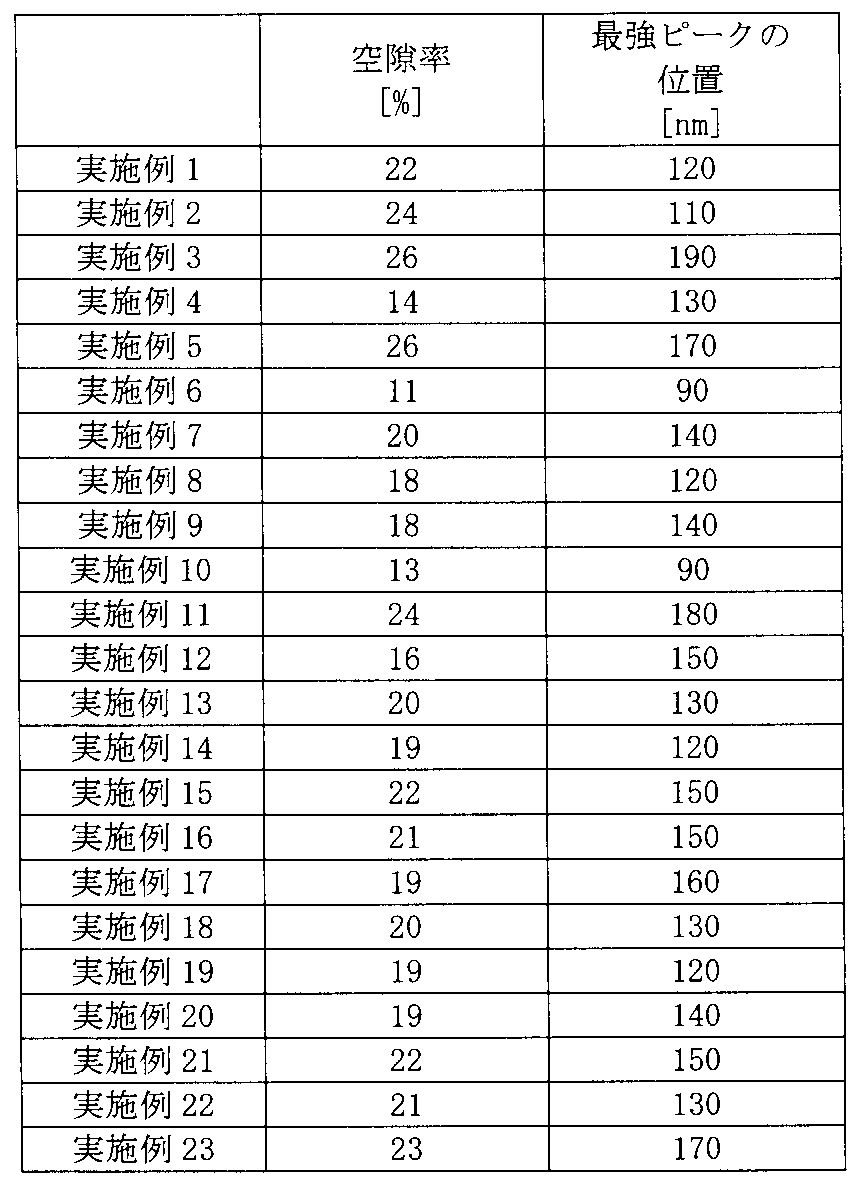
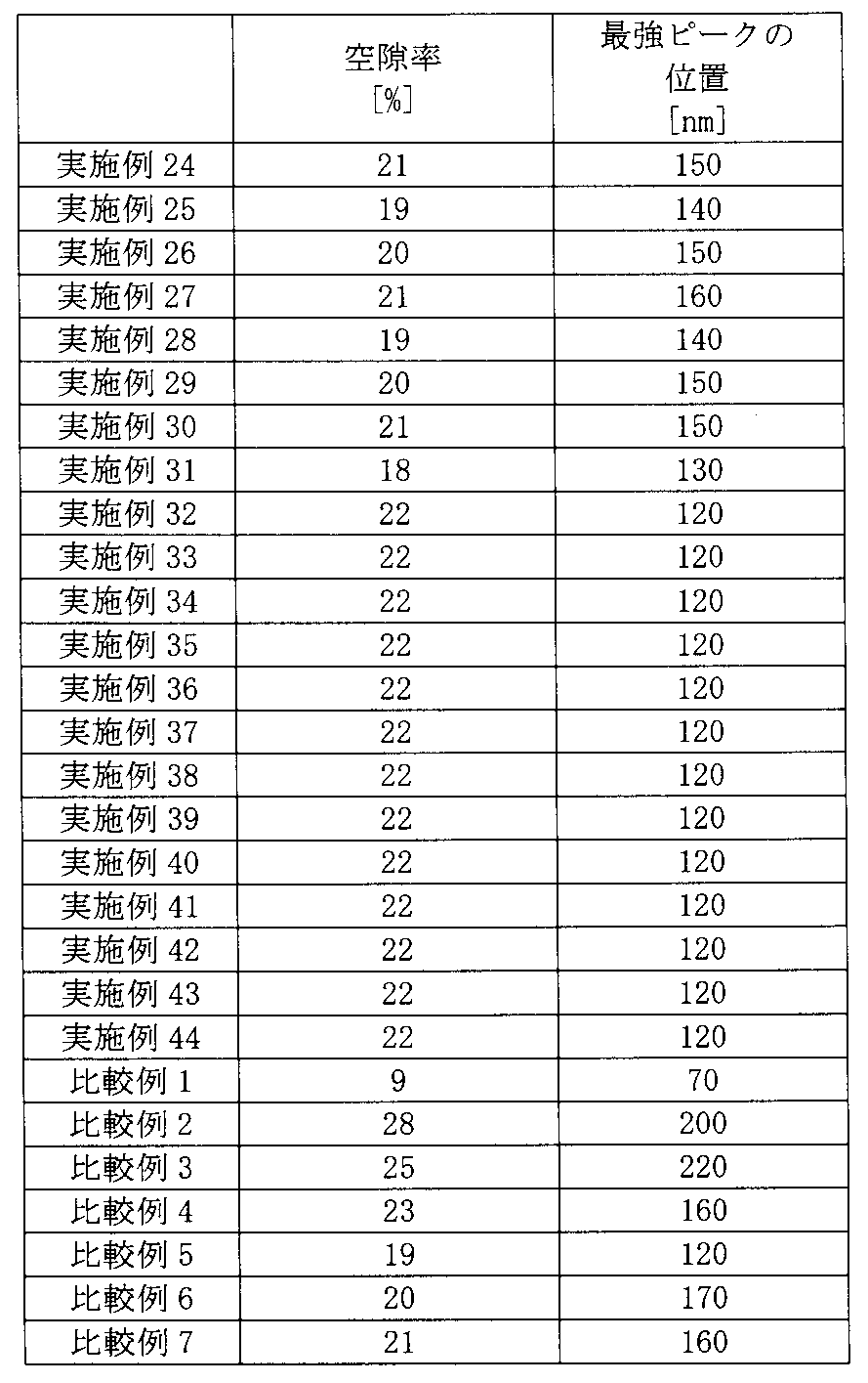
[考察]
表1~4に示した実施例1~6及び比較例1~3の結果の比較により、負極活物質含有層についての水銀圧入法によって得られる空隙率が10%以上26%以下であり、細孔直径分布において細孔直径が200nmより小さい領域に最強ピークが存在する負極は、高SOCの際に低抵抗を示すことができる非水電解質電池を実現することができることがわかる。これは、斜方晶型Na含有ニオブチタン複合酸化物を含む負極活物質含有層内での良好な電子導電性と、電解液の含浸性を両立させたためと考えられる。
表1~4に示した実施例1~6及び比較例1~3の結果の比較により、負極活物質含有層についての水銀圧入法によって得られる空隙率が10%以上26%以下であり、細孔直径分布において細孔直径が200nmより小さい領域に最強ピークが存在する負極は、高SOCの際に低抵抗を示すことができる非水電解質電池を実現することができることがわかる。これは、斜方晶型Na含有ニオブチタン複合酸化物を含む負極活物質含有層内での良好な電子導電性と、電解液の含浸性を両立させたためと考えられる。
また、実施例7~12の結果から、負極に含まれる導電剤にアスペクト比の大きい気相成長炭素繊維やグラファイトを使用した場合も、電極活物質含有層についての水銀圧入法によって得られる空隙率が10%以上26%以下であり、細孔直径分布において細孔直径が200nmより小さい領域に最強ピークが存在する電極は、高SOCの際に低抵抗を示すことができる非水電解質電池を実現することができることがわかる。さらに、導電剤の中でも気相成長炭素繊維は負極活物質含有層内での良好な電子導電経路を形成しやすいため、低抵抗化できることがわかる。
実施例1、及び実施例13~31の結果の比較から、斜方晶型Na含有ニオブチタン複合酸化物におけるM1及び/又はM2を変更しても、高いSOCで低い抵抗値を示すことができる非水電解質電池を実現できたことが分かる。
実施例1及び実施例32~44は、正極活物質が異なる非水電解質電池である。これらの実施例の結果から、正極活物質の中ではスピネル型リチウムマンガン複合酸化物やコバルト酸リチウムを多く含む非水電解質電池において、低抵抗化の効果が高いことがわかる。
比較例4及び5は、負極活物質としてLi4Ti5O12を用いた。比較例4及び5の結果から、負極活物質としてLi4Ti5O12を用いた場合、細孔直径分布の最強ピークを200nmより小さくしても、抵抗が変化しなかったことが分かる。これは、Li4Ti5O12は充電されると電子伝導性が著しく向上するため、粒子同士の接触性の違いによる活物質含有層内の電子伝導性の影響が小さかったためと考えられる。さらに電解液の含浸についても抵抗値が変わるほどの差分がなかったと推測される。なお、電池評価試験の結果、実施例1~44の非水電解質電池は、比較例4及び5よりも、電圧の変化による充電状態の把握が容易であった。また、実施例1の非水電解質電池は、電池電圧が、比較例4及び5のそれよりも高かった。
負極活物質として複合酸化物Li2MgTi6O14及び複合酸化物Li2CaTi6O14をそれぞれ用いた比較例6及び7の非水電解質電池は、負極活物質含有層についての水銀圧入法によって得られる空隙率が10%以上26%以下であり、細孔直径分布において細孔直径が200nmより小さい領域に最強ピークが存在していたが、高SOCでの抵抗が高かった。これは、複合酸化物Li2MgTi6O14及び複合酸化物Li2CaTi6O14の固体内におけるリチウムの拡散の抵抗が大きく、負極活物質含有層の電子導電性の影響が小さかったためと推測される。
以上に説明した1つ以上の実施形態及び実施例によると、電極が提供される。この電極は、集電体と、集電体上に形成された電極活物質含有層とを具備する。電極活物質含有層は、斜方晶型Na含有ニオブチタン複合酸化物の粒子を含む。電極活物質含有層は水銀圧入法によって得られる空隙率が10%以上26%以下である。電極活物質含有層についての水銀圧入法により得られる細孔直径分布において、細孔直径が200nmより小さい領域に最強ピークが存在する。この電極活物質含有層は、斜方晶型Na含有ニオブチタン複合酸化物の粒子が導電パスを十分に形成しており且つ非水電解質の優れた含浸性を示すことができる。そのため、この電極は、優れた入出力特性を示すことができる非水電解質電池を提供することができる。
本発明のいくつかの実施形態を説明したが、これらの実施形態は、例として提示したものであり、発明の範囲を限定することは意図していない。これら新規な実施形態は、その他の様々な形態で実施されることが可能であり、発明の要旨を逸脱しない範囲で、種々の省略、置き換え、変更を行うことができる。これら実施形態やその変形は、発明の範囲や要旨に含まれるとともに、特許請求の範囲に記載された発明とその均等の範囲に含まれる。
1…非水電解質電池、2…外装部材、3…電極群、4…正極、4a…正極集電体、4b…正極活物質含有層、5…電極(負極)、5a…集電体(負極集電体)、5b…電極活物質含有層(負極活物質含有層)、6…セパレータ、7…正極端子、8…負極端子、10…非水電解質電池、11…積層型電極群、12…外装部材、13…正極、13a…集電体、13b…正極活物質含有層、14…負極、14a…集電体、14b…負極活物質含有層、15…セパレータ、16…負極端子、17…正極端子、20…電池パック、21…単電池、22…粘着テープ、23…組電池、24…プリント配線基板、25…サーミスタ、26…保護回路、27…外部端子への通電用端子、37…収納容器、40…リード。
Claims (8)
- 集電体と、
前記集電体上に形成された電極活物質含有層と
を含み、
前記電極活物質含有層は、一般式Li2+vNa2-yM1xTi6-y-zNbyM2zO14+δで表される斜方晶型Na含有ニオブチタン複合酸化物の粒子を含み、
前記一般式において、M1は、Cs、K、Sr、Ba及びCaからなる群より選択される少なくとも1種であり、M2は、Zr、Sn、V、Ta、Mo、W、Fe、Co、Mn及びAlからなる群より選択される少なくとも1種であり、0≦v≦4、0≦x<2、0<y<2、0≦z<3、-0.5≦δ≦0.5であり、
前記電極活物質含有層は、水銀圧入法によって得られる空隙率が10%以上26%以下であり、
前記電極活物質含有層についての前記水銀圧入法により得られる細孔直径分布において、細孔直径が200nmより小さい領域に最強ピークが存在することを特徴とする電極。 - 前記電極活物質含有層は、アスペクト比が15以上である炭素材料粒子を更に含むことを特徴とする請求項1に記載の電極。
- 前記斜方晶型Na含有ニオブチタン複合酸化物の粒子は、一次粒子及び/又は二次粒子の形態にあることを特徴とする請求項1又は2に記載の電極。
- 前記斜方晶型Na含有ニオブチタン複合酸化物の粒子は、5~20μmの範囲内にある平均二次粒子径を有することを特徴とする請求項1又は2に記載の電極。
- 負極としての請求項1~4の何れか1項に記載の電極と、
正極と、
非水電解質と
を具備することを特徴とする非水電解質電池。 - 前記正極は、スピネル型リチウムマンガン複合酸化物を含むことを特徴とする請求項5に記載の非水電解質電池。
- 請求項5又は6の何れか1項に記載の非水電解質電池を具備したことを特徴とする電池パック。
- 複数の前記非水電解質電池を具備し、
前記非水電解質電池は、直列、並列又は直列及び並列の組み合わせで電気的に接続されていることを特徴とする請求項7に記載の電池パック。
Priority Applications (2)
| Application Number | Priority Date | Filing Date | Title |
|---|---|---|---|
| PCT/JP2016/072382 WO2018020668A1 (ja) | 2016-07-29 | 2016-07-29 | 電極、非水電解質電池及び電池パック |
| JP2018530305A JP6571284B2 (ja) | 2016-07-29 | 2016-07-29 | 電極、非水電解質電池及び電池パック |
Applications Claiming Priority (1)
| Application Number | Priority Date | Filing Date | Title |
|---|---|---|---|
| PCT/JP2016/072382 WO2018020668A1 (ja) | 2016-07-29 | 2016-07-29 | 電極、非水電解質電池及び電池パック |
Publications (1)
| Publication Number | Publication Date |
|---|---|
| WO2018020668A1 true WO2018020668A1 (ja) | 2018-02-01 |
Family
ID=61015865
Family Applications (1)
| Application Number | Title | Priority Date | Filing Date |
|---|---|---|---|
| PCT/JP2016/072382 Ceased WO2018020668A1 (ja) | 2016-07-29 | 2016-07-29 | 電極、非水電解質電池及び電池パック |
Country Status (2)
| Country | Link |
|---|---|
| JP (1) | JP6571284B2 (ja) |
| WO (1) | WO2018020668A1 (ja) |
Cited By (8)
| Publication number | Priority date | Publication date | Assignee | Title |
|---|---|---|---|---|
| CN110911660A (zh) * | 2018-09-18 | 2020-03-24 | 株式会社东芝 | 电极、二次电池、电池包及车辆 |
| JP2020119802A (ja) * | 2019-01-25 | 2020-08-06 | トヨタ自動車株式会社 | 全固体リチウムイオン二次電池用負極 |
| CN112652750A (zh) * | 2020-12-22 | 2021-04-13 | 北方奥钛纳米技术有限公司 | 复合负极材料及其制备方法、负极材料及钛酸锂电池 |
| JPWO2020208718A1 (ja) * | 2019-04-09 | 2021-11-25 | 株式会社東芝 | 電極、電極群、電池、及び電池パック |
| US11228031B2 (en) | 2019-09-17 | 2022-01-18 | Kabushiki Kaisha Toshiba | Electrode, secondary battery, battery pack, and vehicle |
| JP2023139647A (ja) * | 2022-03-22 | 2023-10-04 | 株式会社東芝 | 電極、二次電池、電池パック及び車両 |
| JP2024139017A (ja) * | 2023-03-27 | 2024-10-09 | 株式会社東芝 | 電極、二次電池、電池パック、及び車両 |
| WO2026023655A1 (ja) * | 2024-07-26 | 2026-01-29 | Ube株式会社 | ニオブ含有酸化物粉末、それを用いた電極、及び非水電解質蓄電デバイス |
Families Citing this family (1)
| Publication number | Priority date | Publication date | Assignee | Title |
|---|---|---|---|---|
| JP7414439B2 (ja) * | 2019-09-17 | 2024-01-16 | 株式会社東芝 | 二次電池、電池パック及び車両 |
Citations (3)
| Publication number | Priority date | Publication date | Assignee | Title |
|---|---|---|---|---|
| JP2010015904A (ja) * | 2008-07-04 | 2010-01-21 | Nissan Motor Co Ltd | 非水電解液二次電池 |
| WO2015019922A1 (ja) * | 2013-08-07 | 2015-02-12 | トヨタ自動車株式会社 | ナトリウムイオン電池用負極活物質およびナトリウムイオン電池 |
| WO2016084200A1 (ja) * | 2014-11-27 | 2016-06-02 | 株式会社 東芝 | 電池用活物質、非水電解質電池、組電池、電池パック及び自動車 |
-
2016
- 2016-07-29 JP JP2018530305A patent/JP6571284B2/ja not_active Expired - Fee Related
- 2016-07-29 WO PCT/JP2016/072382 patent/WO2018020668A1/ja not_active Ceased
Patent Citations (3)
| Publication number | Priority date | Publication date | Assignee | Title |
|---|---|---|---|---|
| JP2010015904A (ja) * | 2008-07-04 | 2010-01-21 | Nissan Motor Co Ltd | 非水電解液二次電池 |
| WO2015019922A1 (ja) * | 2013-08-07 | 2015-02-12 | トヨタ自動車株式会社 | ナトリウムイオン電池用負極活物質およびナトリウムイオン電池 |
| WO2016084200A1 (ja) * | 2014-11-27 | 2016-06-02 | 株式会社 東芝 | 電池用活物質、非水電解質電池、組電池、電池パック及び自動車 |
Non-Patent Citations (1)
| Title |
|---|
| FUMIO MUTO ET AL.: "Titanium-san Natrium Lithium no Suinetsu Gosei to Kessho Kozo", JOURNAL OF THE CHEMICAL SOCIETY OF JAPAN, vol. 4, 1977, pages 492 - 499 * |
Cited By (16)
| Publication number | Priority date | Publication date | Assignee | Title |
|---|---|---|---|---|
| EP3627596A1 (en) * | 2018-09-18 | 2020-03-25 | Kabushiki Kaisha Toshiba | Electrode, secondary battery, battery pack and vehicle |
| JP2020047437A (ja) * | 2018-09-18 | 2020-03-26 | 株式会社東芝 | 電極、二次電池、電池パック、及び車両 |
| CN110911660A (zh) * | 2018-09-18 | 2020-03-24 | 株式会社东芝 | 电极、二次电池、电池包及车辆 |
| US11211601B2 (en) | 2018-09-18 | 2021-12-28 | Kabushiki Kaisha Toshiba | Electrode, secondary battery, battery pack, and vehicle |
| JP7210198B2 (ja) | 2018-09-18 | 2023-01-23 | 株式会社東芝 | 電極、二次電池、電池パック、及び車両 |
| JP2020119802A (ja) * | 2019-01-25 | 2020-08-06 | トヨタ自動車株式会社 | 全固体リチウムイオン二次電池用負極 |
| JP7111005B2 (ja) | 2019-01-25 | 2022-08-02 | トヨタ自動車株式会社 | 全固体リチウムイオン二次電池用負極 |
| JP7247326B2 (ja) | 2019-04-09 | 2023-03-28 | 株式会社東芝 | 電極、電極群、電池、及び電池パック |
| JPWO2020208718A1 (ja) * | 2019-04-09 | 2021-11-25 | 株式会社東芝 | 電極、電極群、電池、及び電池パック |
| EP3955336A4 (en) * | 2019-04-09 | 2022-03-30 | Kabushiki Kaisha Toshiba | ELECTRODE, ELECTRODE GROUP, BATTERY AND BATTERY PACK |
| US11228031B2 (en) | 2019-09-17 | 2022-01-18 | Kabushiki Kaisha Toshiba | Electrode, secondary battery, battery pack, and vehicle |
| CN112652750A (zh) * | 2020-12-22 | 2021-04-13 | 北方奥钛纳米技术有限公司 | 复合负极材料及其制备方法、负极材料及钛酸锂电池 |
| JP2023139647A (ja) * | 2022-03-22 | 2023-10-04 | 株式会社東芝 | 電極、二次電池、電池パック及び車両 |
| JP7785577B2 (ja) | 2022-03-22 | 2025-12-15 | 株式会社東芝 | 電極、二次電池、電池パック及び車両 |
| JP2024139017A (ja) * | 2023-03-27 | 2024-10-09 | 株式会社東芝 | 電極、二次電池、電池パック、及び車両 |
| WO2026023655A1 (ja) * | 2024-07-26 | 2026-01-29 | Ube株式会社 | ニオブ含有酸化物粉末、それを用いた電極、及び非水電解質蓄電デバイス |
Also Published As
| Publication number | Publication date |
|---|---|
| JPWO2018020668A1 (ja) | 2019-03-07 |
| JP6571284B2 (ja) | 2019-09-04 |
Similar Documents
| Publication | Publication Date | Title |
|---|---|---|
| JP6571284B2 (ja) | 電極、非水電解質電池及び電池パック | |
| JP6523115B2 (ja) | 電池用活物質、負極、非水電解質電池、電池パック及び車 | |
| JP5793442B2 (ja) | 電池用活物質、非水電解質電池及び電池パック | |
| JP6668478B2 (ja) | 非水電解質電池及び電池パック | |
| JP6523892B2 (ja) | 電極、非水電解質電池、電池パック及び車 | |
| JP6096985B1 (ja) | 非水電解質電池及び電池パック | |
| JP6633434B2 (ja) | リチウムイオン二次電池用負極活物質、リチウムイオン二次電池用負極、リチウムイオン二次電池、電池パック及び車両 | |
| US20160268592A1 (en) | Active material, nonaqueous electrolyte battery, and battery pack | |
| CN111727519B (zh) | 电极、电池及电池包 | |
| JP6933771B2 (ja) | 電極群、電池及び電池パック | |
| WO2018020669A1 (ja) | 非水電解質電池及び電池パック | |
| JP6952876B2 (ja) | 電極群、電池、及び電池パック | |
| WO2023079639A1 (ja) | 電極、電池、及び電池パック | |
| CN116114078B (zh) | 电极、电池及电池组 | |
| US12040486B2 (en) | Electrode, electrode group, battery, and battery pack | |
| JP7106754B2 (ja) | 電極、電池及び電池パック | |
| WO2018020670A1 (ja) | 非水電解質電池及び電池パック | |
| JP6992162B2 (ja) | 電池及び電池パック | |
| JP7467162B2 (ja) | 非水電解質電池及び電池パック | |
| WO2023175731A1 (ja) | 電極、電池、及び電池パック | |
| JP2015046400A (ja) | 電池用活物質、非水電解質電池及び電池パック |
Legal Events
| Date | Code | Title | Description |
|---|---|---|---|
| ENP | Entry into the national phase |
Ref document number: 2018530305 Country of ref document: JP Kind code of ref document: A |
|
| 121 | Ep: the epo has been informed by wipo that ep was designated in this application |
Ref document number: 16910571 Country of ref document: EP Kind code of ref document: A1 |
|
| NENP | Non-entry into the national phase |
Ref country code: DE |
|
| 122 | Ep: pct application non-entry in european phase |
Ref document number: 16910571 Country of ref document: EP Kind code of ref document: A1 |