WO2018020569A1 - エッジャの制御装置 - Google Patents
エッジャの制御装置 Download PDFInfo
- Publication number
- WO2018020569A1 WO2018020569A1 PCT/JP2016/071831 JP2016071831W WO2018020569A1 WO 2018020569 A1 WO2018020569 A1 WO 2018020569A1 JP 2016071831 W JP2016071831 W JP 2016071831W WO 2018020569 A1 WO2018020569 A1 WO 2018020569A1
- Authority
- WO
- WIPO (PCT)
- Prior art keywords
- edger
- opening pattern
- end opening
- rolled
- width
- Prior art date
- Legal status (The legal status is an assumption and is not a legal conclusion. Google has not performed a legal analysis and makes no representation as to the accuracy of the status listed.)
- Ceased
Links
Images





Classifications
-
- B—PERFORMING OPERATIONS; TRANSPORTING
- B21—MECHANICAL METAL-WORKING WITHOUT ESSENTIALLY REMOVING MATERIAL; PUNCHING METAL
- B21B—ROLLING OF METAL
- B21B37/00—Control devices or methods specially adapted for metal-rolling mills or the work produced thereby
- B21B37/16—Control of thickness, width, diameter or other transverse dimensions
- B21B37/22—Lateral spread control; Width control, e.g. by edge rolling
Definitions
- This invention relates to an edger control device.
- Patent Document 1 discloses an edger control device.
- the said control apparatus corrects a typical board width prediction pattern. As a result, the accuracy of the dimension in the width direction of the product can be improved.
- the same sheet width prediction pattern may be set for the materials to be rolled having different sheet width fluctuations. For this reason, the width dimension of a product may become non-uniform
- An object of the present invention is to provide an edger control device capable of improving the accuracy of the width dimension of a product.
- An edger control device includes a pass schedule determiner that determines a gap of an edger roll based on a plate thickness and a plate width of a rolled material before rolling and a target plate width of the rolled material after rolling.
- the edger leading edge opening pattern generation for generating the edger leading edge opening pattern so as to match the unsteady portion of the leading edge of the material to be rolled with the target plate width based on the information from the pass schedule determiner And the edger roll opening pattern generated by the edger leading edge opening pattern generator and the edger leading edge opening pattern generated by the edger leading edge opening pattern generator.
- An edger leading end opening controller for controlling the degree, an entry side width record data collector for collecting the detected value of the actual sheet width of the material to be rolled on the entry side of the edger, and the edge Based on the detected value of the actual sheet width of the rolled material collected by the outgoing width actual data collector that collects the detected value of the actual sheet width of the rolled material on the outlet side
- An edge side leading end opening pattern correction unit for calculating an edge side leading end opening degree pattern correction amount for the edger leading end opening degree controller based on the input side width deviation; Edger leading edge opening pattern generated by the edger leading edge opening pattern generator, actual plate width detection value of the rolled material collected by the outlet width actual data collector, and the edger leading edge Edger leading end opening pattern correction correction for calculating an edger leading end opening pattern correction correction term for the edger leading end opening pattern correction unit based on the input side width deviation calculated by the opening pattern correction unit.
- the edger leading end opening pattern is corrected based on the edger leading end opening pattern correction amount.
- the edger leading end opening pattern correction amount is corrected based on the edger leading end opening pattern correction correction term. For this reason, the precision of the width dimension of a product can be improved.
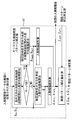
- FIG. 1 It is a block diagram of the roughing process of the hot rolling line to which the edger control apparatus in Embodiment 1 of this invention is applied. It is a block diagram of the edger leading end opening pattern corrector of the edger control device in Embodiment 1 of this invention. It is a block diagram of the edger leading end opening pattern correction corrector of the edger control device according to Embodiment 1 of the present invention. It is a figure which shows the actual board width
- FIG. 1 It is a figure which shows the edger tip end opening degree pattern produced
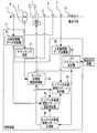
- FIG. 1 is a configuration diagram of a rough pressure process in a hot rolling line to which an edger control device according to Embodiment 1 of the present invention is applied.
- the rough rolling process of the hot rolling line is provided on the downstream side of a heating furnace (not shown).
- the rough rolling process of the hot rolling line is provided on the upstream side of the finish rolling process (not shown).
- At least one edger 1 is provided on the upstream side of the rough rolling process of the hot rolling line.
- the edger 1 includes a roll 1a and a hydraulic cylinder 1b.
- At least one horizontal mill 2 is provided downstream of at least one edger 1.
- the entrance width meter 3 is provided on the upstream side of at least one edger 1.
- the roller table speed detector 4 is provided between at least one edger 1 and the entrance width meter 3.
- the hot piece detector 5 is provided between at least one edger 1 and the roller table speed detector 4.
- the rotational speed detector 6 is provided in at least one horizontal mill 2.
- the exit width meter 7 is provided on the downstream side of the horizontal mill 2.
- the input unit of the tracking device 8 is connected to the output unit of the roller table speed detector 4.
- the input unit of the tracking device 8 is connected to the output unit of the rotation speed detector 6.
- the control device 9 includes a path schedule determiner 9a, an edger leading end opening pattern generator 9b, an edger leading end opening controller 9c, an input side width actual data collector 9d, and an output side width actual data collector 9e.
- An edger leading end opening pattern corrector 9f and an edger leading end opening pattern correction corrector 9g are provided.
- the material to be rolled 10 is conveyed from the upstream side to the downstream side.
- the end on the upstream side of the material to be rolled 10 is defined as the tip.
- the downstream end of the material to be rolled 10 is defined as the tail end.
- the roll 1a opens and closes in the sheet width direction of the material to be rolled 10, thereby rolling the material to be rolled 10 in the sheet width direction.
- At least one horizontal mill 2 rolls the material to be rolled 10 in the plate thickness direction by opening and closing in the plate thickness direction of the material 10 to be rolled.
- the entrance width meter 3 detects the actual sheet width of the material 10 to be rolled.
- the roller table speed detector 4 detects the speed of a roller table (not shown).
- the hot piece detector 5 detects the material to be rolled 10.
- the rotational speed detector 6 detects the rotational speed of at least one horizontal mill 2.
- the delivery width meter 7 detects the actual sheet width of the material to be rolled 10.
- the tracking device 8 generates tracking information of the transport position of the material to be rolled 10 based on the detection value of the roller table speed detector 4 and the detection value of the rotation speed detector 6.
- the pass schedule determining unit 9a receives hot rolling instruction information from a host computer (not shown).
- the pass schedule determiner 9a receives steel type information.
- the pass schedule determiner 9a receives information on the dimensions of the material 10 to be rolled before rolling.
- the pass schedule determiner 9a receives information on the target dimension of the rolled material 10 after rolling.
- the pass schedule determiner 9a determines the rotation speed of the roll 1a and the opening degree of the roll 1a so that a product having a preset size is manufactured.
- the pass schedule determiner 9a determines each opening based on information on the thickness and width of the material 10 before rolling and the target width of the material 10 after rolling in determining the opening degree of the roll 1a. The opening degree of the roll 1a is determined. At this time, the pass schedule determiner 9a determines the opening degree of the roll 1a with respect to the target plate width of the steady portion of the material to be rolled 10 in a preset pass.
- the edger leading end opening pattern generator 9b generates an edger leading end opening pattern so that the unsteady portion of the leading end of the material to be rolled 10 matches the target plate width.
- the edger leading end opening pattern generator 9b includes a plurality of edger tips based on information on the steel type from the pass schedule determiner 9a and the sheet thickness, sheet width, and width reduction amount of the material to be rolled 10 before rolling.
- a specific edger tip end opening pattern is indexed from a numerical table storing information on the tail end opening pattern.
- the edger leading end opening pattern generator 9b generates a specific edger leading end opening pattern based on a preset mathematical expression.
- the edger leading end opening controller 9c is based on the gap of the roll 1a determined by the path schedule determining unit 9a and the edger leading end opening pattern generated by the edger leading end opening pattern generator 9b.
- the opening degree of the roll 1a is controlled.
- the edger leading end opening controller 9c changes the opening degree of the edger 1 based on the edger leading end opening pattern at an appropriate position of the material to be rolled 10 based on the tracking information of the conveyance position of the material 10 to be rolled. Thus, a signal is transmitted to the hydraulic cylinder 1b.
- Entry side width result data collector 9d collects the detected value of entry side width meter 3.
- the delivery width actual data collector 9e collects the detection value of the delivery width meter 7.
- the edger leading end opening degree pattern corrector 9f calculates the entry side width deviation of the material to be rolled 10 based on the detected value collected by the entry side width record data collector 9d.
- the edger leading end opening pattern corrector 9f calculates an edger leading end opening pattern correction amount for the edger leading end opening controller 9c based on the incoming width deviation.
- the edger leading edge opening pattern correction corrector 9g includes the edger leading edge opening pattern generated by the edger leading edge opening pattern generator 9b and the detection value collected by the outgoing side width actual data collector 9e.
- An edger leading end opening degree pattern correction correction term for the edger leading end opening degree pattern corrector 9f is calculated based on the input side width deviation calculated by the edger leading end opening degree pattern corrector 9f.
- FIG. 2 is a block diagram of an edger leading end opening pattern corrector of the edger control apparatus according to Embodiment 1 of the present invention.
- the edger leading end opening degree pattern corrector 9f is based on the detection value collected by the entry side width record data collector 9d, and the entry side average plate width B ave (mm) at the center in the longitudinal direction of the material 10 to be rolled. Is calculated. Specifically, the entry-side average plate width B ave (mm) is calculated by the following equation (1).
- L head is an edger opening change end position at the front end of the material to be rolled 10 in the longitudinal direction.
- the unit of L head is (mm).
- L tail is an edger opening change start position at the tail end in the longitudinal direction of the material 10 to be rolled.
- the unit of L tail is (mm).
- B (x) is the entry side plate width in the longitudinal direction of the material to be rolled 10.
- the unit of B (x) is (mm).
- x is the distance from the front end of the material to be rolled 10 in the longitudinal direction.
- the unit of x is (mm).
- the edger leading end opening degree pattern corrector 9f is a performance plate of the tip end in the longitudinal direction of the material to be rolled 10 at a control point L i obtained by dividing the longitudinal tip by applying an edger tip opening change at an arbitrary length.
- An entry-side width deviation ⁇ Hi (mm) between the width B Hi (mm) and the entry-side average plate width B ave (mm) is calculated.
- the entry-side width deviation ⁇ Hi (mm) is calculated by the following equation (2).
- Edger destination tail opening pattern corrector 9f are longitudinal tail end of the longitudinal tail end to be rolled material 10 at the control point L j divided by an arbitrary length of the application of edger tail opening degree variation
- the entry side width deviation ⁇ Tj (mm) between the actual plate width B Tj (mm) and the entry side average plate width B ave (mm) is calculated.
- the entry-side width deviation ⁇ Tj (mm) is calculated by the following equation (3).
- j is from 1 to n.
- Edger destination tail opening pattern corrector 9f is actual strip width B Hi (mm) and the edger tip opening pattern correction term Z OmegaHi and edger at the control point L i based on the front end opening pattern correction amount [Delta] [omega Hi ( mm). Specifically, the edger tip opening pattern correction amount ⁇ Hi (mm) is calculated by the following equation (4).
- Edger destination tail opening pattern corrector 9f is actual strip width B Tj (mm) and the edger tail end opening pattern correction term Z OmegaTj edger tail opening pattern correction amount in the control point L j on the basis of the ⁇ Tj (mm) is calculated. Specifically, the edger tail end opening pattern correction amount ⁇ Tj (mm) is calculated by the following equation (5).
- FIG. 3 is a block diagram of the edger leading end opening pattern correction corrector of the edger control apparatus according to Embodiment 1 of the present invention.
- the edger leading end opening degree pattern correction corrector 9g is based on the detected value collected by the exit width actual data collector 9e, and the average plate width B ′ at the center in the longitudinal direction of the material 10 after horizontal rolling. ave (mm) is calculated. Specifically, the average plate width B ′ ave (mm) is calculated by the following equation (6).
- L ' head is an edger opening change end position at the front end in the longitudinal direction of the material 10 after horizontal rolling.
- the unit of L ′ head is (mm).
- L ′ tail is an edger opening change start position at the tail end in the longitudinal direction of the material 10 after horizontal rolling.
- the unit of L ′ tail is (mm).
- B ′ (x) is the entry side plate width in the longitudinal direction of the material to be rolled 10.
- the unit of B ′ (x) is (mm).
- x ′ is the distance from the tip of the material to be rolled 10 in the longitudinal direction.
- the unit of x ′ is (mm).
- the edger opening change end position L ′ head at the front end in the longitudinal direction of the material 10 to be rolled after horizontal rolling is calculated by the following equation (7).
- Edger 1 opening change start position L'tail longitudinal tail end of the rolled material 10 after horizontal rolling is calculated by the following equation (8).
- the edger leading end opening pattern correction corrector 9g is the actual plate width B ′ Hi (mm) at the front end in the longitudinal direction of the material 10 after horizontal rolling at the control point L ′ i corresponding to the control point L i .
- the exit side plate width deviation ⁇ ′ Hi (mm) is calculated by the following equation (9).
- control point L ′ i corresponding to the control point L i is calculated by the following equation (10).
- the edger leading end opening pattern correction corrector 9g has a result plate width B ′ Tj (mm at the tail end in the longitudinal direction of the material 10 after horizontal rolling at the control point L ′ j corresponding to the control point L j . ) And the output side average plate width B ′ ave (mm) of the central portion, the output side plate width deviation ⁇ ′ Tj (mm) is calculated. Specifically, delivery side width deviation ⁇ ' Tj (mm) is calculated by the following equation (11).
- control point L ′ j corresponding to the control point L j is calculated by the following equation (12).
- the exit sheet width deviation is not calculated. Furthermore, the value regarding the tail end part of the subsequent to-be-rolled material 10 is not calculated.
- Edger destination tail opening pattern correction modifier 9g may exit calculate the amount of side plate width deviation ⁇ ' Hi (mm) to contribute previous entry side width deviation ⁇ Hi (mm) as edger tip opening pattern correction ratio amount To do.
- the edger tip opening pattern correction ratio ⁇ Hi (mm) is a simple ratio of the previous side width deviation ⁇ Hi (mm) to the edger tip opening change amount in the previous edger tip opening pattern.
- the edger tip opening pattern correction ratio ⁇ Hi (mm) is calculated by the following equation (13).
- ⁇ S Hi is an edger tip opening change amount of the previous edger tip opening pattern.
- the unit of the edger tip opening change amount ⁇ S Hi is (mm).
- Edger destination tail opening pattern correction modifier 9g as edger tail opening pattern correction ratio amount the amount of delivery side width deviation Derutaomega' Tj inlet side width of the previous contribute to (mm) deviation [Delta] [omega Tj (mm) calculate.
- the edger tail end opening pattern correction ratio ⁇ Tj (mm) is a simple ratio of the previous entry side width deviation to the edger tip opening change amount in the previous edger tail end opening pattern.
- the edger tail end opening pattern correction ratio ⁇ Tj is calculated by the following equation (14).
- ⁇ S Tj is the edger tail end opening change amount of the previous edger tail end opening pattern.
- Units of edger tail opening change amount [Delta] S Tj is (mm).
- Edger destination tail opening pattern correction modifier 9g calculates the edger tip opening pattern correction correction term Z OmegaHi to optimize the edger tip opening pattern correction amount. Specifically, the edger tip opening pattern correction correction term Z ⁇ Hi is calculated by the following (15).
- Edger tip opening pattern correction amount correction term Z OmegaHi is multiplied edger tip opening pattern correction amount [Delta] [omega Hi of the following material to be rolled 10.
- the edger tip opening pattern correction amount ⁇ Hi of the next material to be rolled 10 is calculated by the following equation (16).
- BnHi is the actual sheet width of the next material 10 to be rolled.
- the unit of B nHi is (mm).
- B n ave is the entry-side average plate width at the center in the longitudinal direction of the next material to be rolled 10.
- the unit of B n ave is (mm).
- Edger destination tail opening pattern correction modifier 9g calculates the edger tail opening pattern correction correction term Z OmegaTj to optimize the edger tail opening pattern correction amount. Specifically, the edger tail end opening pattern correction correction term Z ⁇ Tj is calculated by the following (17).
- edger tail end opening pattern correction amount correction term Z ⁇ Tj is multiplied by the edger tail end opening pattern correction amount ⁇ Tj of the next material to be rolled 10.
- the edger tail end opening pattern correction amount ⁇ Tj of the next material to be rolled 10 is calculated by the following equation (18).
- B nTj is the actual sheet width of the next material to be rolled 10.
- the unit of B nTj is (mm).
- B n ave is the entry-side average plate width at the center in the longitudinal direction of the next material to be rolled 10.
- the unit of B n ave is (mm).
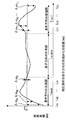
- FIG. 4 is a diagram showing the actual sheet width of the material to be rolled used in the edger control apparatus according to Embodiment 1 of the present invention.
- the horizontal axis in FIG. 4 is the distance (mm) from the tip in the longitudinal direction of the material to be rolled 10.
- the vertical axis in FIG. 4 is the actual sheet width (mm) of the material 10 to be rolled.
- the entry side width meter 3 detects the actual sheet width (mm) of the front end portion in the longitudinal direction of the material to be rolled 10 before rolling at the control point Li.
- the entry side width meter 3 detects the actual sheet width (mm) of the tail end portion in the longitudinal direction of the material to be rolled 10 before rolling at the control point Lj.
- i and j are 1 to n.
- n is set based on the response speed of the hydraulic cylinder 1b.
- n is set based on the performance of various controllers.
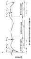
- FIG. 5 is a diagram showing the actual sheet width of the material to be rolled used in the edger control apparatus according to Embodiment 1 of the present invention.
- the horizontal axis in FIG. 5 is the distance (mm) from the tip in the longitudinal direction of the material to be rolled 10.
- the vertical axis in FIG. 5 is the actual sheet width (mm) of the material 10 to be rolled.
- tip part, center part, and tail end part of the longitudinal direction of the to-be-rolled material 10 after rolling are the front-end
- the exit width meter 7 detects the actual sheet width (mm) at the front end in the longitudinal direction of the rolled material 10 after rolling at the control point L′ i.
- the exit width meter 7 detects the actual sheet width (mm) of the tail end portion in the longitudinal direction of the material 10 after rolling at the control point L′ j.
- FIG. 6 is a diagram showing an edger leading end opening pattern generated by the edger control device according to Embodiment 1 of the present invention.
- the horizontal axis in FIG. 6A is the distance (mm) from the tip in the longitudinal direction of the material to be rolled 10.
- the vertical axis in FIG. 6A is the edger tip opening pattern (mm) or the edger tip opening pattern correction amount (mm).
- the horizontal axis of FIG. 6B is the distance (mm) from the edger opening change start position of the tail end portion in the longitudinal direction of the material 10 to be rolled.
- the vertical axis in FIG. 6A is the edger tail end opening pattern (mm) or the edger tail end opening pattern correction amount (mm).
- the edger tip opening pattern correction amount (mm) is added to the edger tip opening pattern (mm) generated by the edger leading end opening pattern generator 9b. . As a result, a corrected edger tip opening pattern (mm) is newly set.
- the edger tail end opening pattern correction amount (mm) is added to the edger tail end opening pattern (mm) generated by the edger tail end opening pattern generator 9b. Is done. As a result, a corrected edger tail end opening pattern (mm) is newly set.
- FIG. 7 is a flowchart for explaining the outline of the operation of the edger control device according to the first embodiment of the present invention.
- step S1 the control device 9 determines whether or not the hot rolling instruction information has been received. When the control device 9 has not received the hot rolling instruction information in step S1, the control device 9 repeats the operation of step S1. When the control device 9 receives the hot rolling command information in step S1, the control device 9 performs the operation of step S2.
- step S2 the control device 9 determines the opening degree of the roll 1a with respect to the target plate width of the steady portion of the material 10 to be rolled in a preset pass. Thereafter, the control device 9 performs the operation of step S3.
- step S ⁇ b> 3 the control device 9 generates an edger leading end opening pattern so that the unsteady portion at the leading end of the material to be rolled 10 matches the target plate width. Thereafter, the control device 9 performs the operation of step S4.
- step S ⁇ b> 4 the control device 9 changes the opening of the edger 1 based on the edger leading end opening pattern at an appropriate position of the material to be rolled 10 based on the tracking information of the conveyance position of the material to be rolled 10. A signal is transmitted to the hydraulic cylinder 1b. Thereafter, the control device 9 performs the operation of step S5.
- step S5 the control device 9 calculates an edger leading end opening pattern correction amount. Thereafter, the control device 9 performs the operation of step S6. In step S6, an edger leading end opening pattern correction correction term is calculated. Thereafter, the control device 9 ends the operation.
- the edger leading end opening pattern is automatically corrected based on the edger leading end opening pattern correction amount.
- the edger leading end opening pattern correction amount is automatically corrected based on the edger leading end opening pattern correction correction term. For this reason, in the next to-be-rolled material 10, the precision of the width dimension of a product can be improved. Furthermore, if the number of rolling increases, the edger leading end opening pattern correction correction term can be set more appropriately.
- the edger leading end opening pattern is corrected based on the exit side width deviation of the material to be rolled 10 caused only by the entry side width deviation of the material to be rolled 10. For this reason, the width
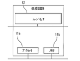
- FIG. 8 is a hardware configuration diagram of the edger control device according to the first embodiment of the present invention.
- Each function of the control device 9 can be realized by a processing circuit.
- the processing circuit includes at least one processor 11a and at least one memory 11b.
- the processing circuit comprises at least one dedicated hardware 12.
- each function of the control device 9 is realized by software, firmware, or a combination of software and firmware. At least one of software and firmware is described as a program. At least one of software and firmware is stored in at least one memory 11b. At least one processor 11a implements each function of the control device 9 by reading and executing a program stored in at least one memory 11b.
- the at least one processor 11a is also referred to as a CPU (Central Processing Unit), a central processing unit, a processing unit, an arithmetic unit, a microprocessor, a microcomputer, and a DSP.
- the at least one memory 11b is a nonvolatile or volatile semiconductor memory such as a RAM, a ROM, a flash memory, an EPROM, or an EEPROM, a magnetic disk, a flexible disk, an optical disk, a compact disk, a mini disk, a DVD, or the like.
- a nonvolatile or volatile semiconductor memory such as a RAM, a ROM, a flash memory, an EPROM, or an EEPROM, a magnetic disk, a flexible disk, an optical disk, a compact disk, a mini disk, a DVD, or the like.
- the processing circuit comprises at least one dedicated hardware 12, the processing circuit is implemented, for example, as a single circuit, a composite circuit, a programmed processor, a parallel programmed processor, an ASIC, an FPGA, or a combination thereof.
- each function of the control device 9 is realized by a processing circuit.
- each function of the control device 9 is collectively realized by a processing circuit.
- control device 9 may be realized by the dedicated hardware 12, and the other part may be realized by software or firmware.
- the function of the path schedule determiner 9a is realized by a processing circuit as the dedicated hardware 12, and for functions other than the path schedule determiner 9a, at least one processor 11a is stored in at least one memory 11b. May be realized by reading out and executing.
- the processing circuit realizes each function of the control device 9 by the hardware 12, software, firmware, or a combination thereof.
- FIG. FIG. 9 is a block diagram of an edger leading end opening pattern corrector of the control device for edger 1 according to Embodiment 2 of the present invention.
- symbol is attached
- Edger destination tail opening pattern corrector 9f calculates the inlet side mean plate width B head ave of the rolled material 10 (mm) in the longitudinal direction central portion near the tip section L hm (mm). Specifically, the entry side average plate width B head ave (mm) is calculated by the following equation (19).
- the edger leading end opening degree pattern corrector 9f calculates the entry-side average plate width B tail ave (mm) of the material to be rolled 10 in the tail end vicinity section L tm (mm) at the center in the longitudinal direction. Specifically, the entry side average plate width B head ave (mm) is calculated by the following equation (20).
- Edger destination tail opening pattern corrector 9f is entry-side mean plate width B head ave (mm) and the entry side mean plate width B tail ave (mm) and the absolute value of the previous tail edge near the average width deviation of the deviation of ( mm). Specifically, the leading edge vicinity average width deviation (mm) is calculated by the following equation (21).
- the edger leading end opening pattern corrector 9f determines that the shape of the material to be rolled 10 is not tapered.
- the edger leading end opening degree pattern corrector 9f determines that the shape of the material to be rolled 10 is a rectangular shape having a certain width deviation.
- the edger leading end opening pattern correction unit 9f calculates the edger tip opening pattern correction amount ⁇ Hi and the edger tail end opening pattern correction amount ⁇ Tj , as in the first embodiment.
- the edger leading end opening pattern corrector 9f determines that the shape of the material to be rolled 10 is tapered.
- the edger leading end opening degree pattern corrector 9f has the actual plate width B Hi (mm) at the front end in the longitudinal direction of the material to be rolled 10 at the control point L i and the entry side average plate width of the material to be rolled 10.
- An entry side width deviation ⁇ Hi (mm) with respect to B head ave (mm) is calculated.
- the entry-side width deviation ⁇ Hi (mm) is calculated by the following equation (22).
- edger destination tail opening pattern corrector 9f is inlet side width results in the longitudinal direction of the tail end of the rolled material 10 at the control point L j
- An entry-side width deviation ⁇ Tj (mm) between the value B Tj (mm) and the entry-side average sheet width B tail ave (mm) of the material to be rolled 10 is calculated.
- the entry-side width deviation ⁇ Tj (mm) is calculated by the following equation (23).
- the edger leading end opening pattern corrector 9f uses the entrance side width deviation ⁇ Hi (mm) in the equation (22) to set the edger tip opening.
- the pattern correction amount ⁇ Hi is calculated.
- the edger leading end opening pattern corrector 9f calculates the edger tail end opening pattern correction amount ⁇ Tj by using the entry-side width deviation ⁇ Tj (mm) of equation (23).
- FIG. 10 is a diagram showing the actual sheet width of the material to be rolled used in the edger control device according to Embodiment 2 of the present invention.
- the horizontal axis in FIG. 10 is the distance (mm) from the tip in the longitudinal direction of the material to be rolled 10.
- the vertical axis in FIG. 10 is the actual sheet width (mm) of the material 10 to be rolled.
- tip part of the longitudinal direction of the to-be-rolled material 10 before rolling, a center part, and a tail end part are set suitably.
- the front end vicinity section L hm (mm) at the longitudinal center and the tail end vicinity section L tm (mm) at the longitudinal center are set as appropriate.
- the plate width of the material to be rolled 10 becomes wider from the tip toward the tail.
- the leading end vicinity average width deviation (mm) of the equation (21) is equal to or larger than a preset k, the rolled material 10 is determined to be tapered.
- the edger leading end opening pattern correction amount differs between the case where the shape of the material to be rolled 10 is not tapered and the case where the shape of the material to be rolled 10 is tapered. Calculated by the method. For this reason, even when the shape of the material to be rolled is tapered, it is possible to extract only the entry-side width deviation and cancel the deviation.
- the edger control device can be used in a system that improves the accuracy of the product width dimension.
Landscapes
- Engineering & Computer Science (AREA)
- Mechanical Engineering (AREA)
- Control Of Metal Rolling (AREA)
Abstract
製品の幅寸法の精度を向上することができるエッジャの制御装置を提供する。エッジャの制御装置は、入側幅実績データ収集器により収集された被圧延材の実績板幅の検出値に基づいて入側幅偏差を算出し、当該入側幅偏差に基づいてエッジャ先尾端開度制御器に対するエッジャ先尾端開度パターン補正量を算出するエッジャ先尾端開度パターン補正器と、エッジャ先尾端開度パターン生成器により生成されたエッジャ先尾端開度パターンと出側幅実績データ収集器により収集された被圧延材の実績板幅の検出値とエッジャ先尾端開度パターン補正器により算出された入側幅偏差とに基づいてエッジャ先尾端開度パターン補正器に対するエッジャ先尾端開度パターン補正修正項を算出するエッジャ先尾端開度パターン補正修正器と、を備えた。
Description
この発明は、エッジャの制御装置に関する。
特許文献1は、エッジャの制御装置を開示する。当該制御装置は、代表的な板幅予測パターンに修正を加える。その結果、製品の幅方向の寸法の精度が向上し得る。
しかしながら、特許文献1に記載の制御装置においては、板幅変動が異なる被圧延材に対し、同じ板幅予測パターンが設定されることもある。このため、製品の幅寸法が不均一となり得る。
この発明は、上述の課題を解決するためになされた。この発明の目的は、製品の幅寸法の精度を向上することができるエッジャの制御装置を提供することである。
この発明に係るエッジャの制御装置は、圧延前の被圧延材の板厚と板幅と圧延後の被圧延材の目標板幅とに基づいてエッジャのロールのギャップを決定するパススケジュール決定器と、前記パススケジュール決定器からの情報に基づいて被圧延材の先尾端の非定常部を目標板幅と一致させるようにエッジャ先尾端開度パターンを生成するエッジャ先尾端開度パターン生成器と、前記パススケジュール決定器により決定された前記エッジャのロールのギャップと前記エッジャ先尾端開度パターン生成器により生成されたエッジャ先尾端開度パターンとに基づいて前記エッジャのロールの開度を制御するエッジャ先尾端開度制御器と、前記エッジャの入側における被圧延材の実績板幅の検出値を収集する入側幅実績データ収集器と、前記エッジャの出側における被圧延材の実績板幅の検出値を収集する出側幅実績データ収集器と、前記入側幅実績データ収集器により収集された被圧延材の実績板幅の検出値に基づいて入側幅偏差を算出し、当該入側幅偏差に基づいて前記エッジャ先尾端開度制御器に対するエッジャ先尾端開度パターン補正量を算出するエッジャ先尾端開度パターン補正器と、前記エッジャ先尾端開度パターン生成器により生成されたエッジャ先尾端開度パターンと前記出側幅実績データ収集器により収集された被圧延材の実績板幅の検出値と前記エッジャ先尾端開度パターン補正器により算出された入側幅偏差とに基づいて前記エッジャ先尾端開度パターン補正器に対するエッジャ先尾端開度パターン補正修正項を算出するエッジャ先尾端開度パターン補正修正器と、を備えた。
この発明によれば、エッジャ先尾端開度パターンは、エッジャ先尾端開度パターン補正量に基づいて補正される。エッジャ先尾端開度パターン補正量は、エッジャ先尾端開度パターン補正修正項に基づいて補正される。このため、製品の幅寸法の精度を向上することができる。
この発明を実施するための形態について添付の図面に従って説明する。なお、各図中、同一または相当する部分には同一の符号が付される。当該部分の重複説明は適宜に簡略化ないし省略する。
実施の形態1.
図1はこの発明の実施の形態1におけるエッジャの制御装置が適用される熱間圧延ラインの粗圧工程の構成図である。
図1はこの発明の実施の形態1におけるエッジャの制御装置が適用される熱間圧延ラインの粗圧工程の構成図である。
図1において、熱間圧延ラインの粗圧延工程は、図示されない加熱炉よりも下流側に設けられる。熱間圧延ラインの粗圧延工程は、図示されない仕上圧延工程よりも上流側に設けられる。
少なくとも一つのエッジャ1は、熱間圧延ラインの粗圧延工程の上流側に設けられる。エッジャ1は、ロール1aと油圧シリンダ1bとを備える。少なくとも一つの水平ミル2は、少なくとも一つのエッジャ1よりも下流側に設けられる。
入側幅計3は、少なくとも一つのエッジャ1よりも上流側に設けられる。ローラテーブル速度検出器4は、少なくとも一つのエッジャ1と入側幅計3との間に設けられる。熱片検出器5は、少なくとも一つのエッジャ1とローラテーブル速度検出器4との間に設けられる。回転速度検出器6は、少なくとも一つの水平ミル2に設けられる。出側幅計7は、水平ミル2よりも下流側に設けられる。
トラッキング装置8の入力部は、ローラテーブル速度検出器4の出力部に接続される。トラッキング装置8の入力部は、回転速度検出器6の出力部に接続される。
制御装置9は、パススケジュール決定器9aとエッジャ先尾端開度パターン生成器9bとエッジャ先尾端開度制御器9cと入側幅実績データ収集器9dと出側幅実績データ収集器9eとエッジャ先尾端開度パターン補正器9fとエッジャ先尾端開度パターン補正修正器9gとを備える。
1回目の正パスにおいて、被圧延材10は、上流側から下流側へ搬送される。被圧延材10の上流側の端部は、先端部と定義される。被圧延材10の下流側の端部は、尾端部と定義される。
少なくとも一つのエッジャ1において、油圧シリンダ1bが油圧制御されると、ロール1aは、被圧延材10の板幅方向に開閉することにより被圧延材10を板幅方向に圧延する。少なくとも一つの水平ミル2は、被圧延材10の板厚方向に開閉することにより被圧延材10を板厚方向に圧延する。
入側幅計3は、被圧延材10の実績板幅を検出する。ローラテーブル速度検出器4は、図示されないローラテーブルの速度を検出する。熱片検出器5は、被圧延材10を検出する。回転速度検出器6は、少なくとも一つの水平ミル2の回転速度を検出する。出側幅計7は、被圧延材10の実績板幅を検出する。
トラッキング装置8は、ローラテーブル速度検出器4の検出値と回転速度検出器6の検出値とに基づいて被圧延材10の搬送位置のトラッキング情報を生成する。
被圧延材10が熱間圧延ラインにおいて予め設定された位置に到達すると、パススケジュール決定器9aは、図示されない上位計算機から熱延命令情報を受信する。例えば、パススケジュール決定器9aは、鋼種の情報を受信する。例えば、パススケジュール決定器9aは、圧延前の被圧延材10の寸法の情報を受信する。例えば、パススケジュール決定器9aは、圧延後の被圧延材10の目標寸法の情報を受信する。パススケジュール決定器9aは、予め設定された寸法の製品が製造されるようにロール1aの回転数とロール1aの開度とを決定する。
例えば、パススケジュール決定器9aは、ロール1aの開度の決定において圧延前の被圧延材10の板厚と板幅と圧延後の被圧延材10の目標板幅との情報に基づいて各パスのロール1aの開度を決定する。この際、パススケジュール決定器9aは、予め設定されたパスにおける被圧延材10の定常部の目標板幅に対するロール1aの開度を決定する。
エッジャ先尾端開度パターン生成器9bは、被圧延材10の先尾端の非定常部を目標板幅と一致させるようにエッジャ先尾端開度パターンを生成する。例えば、エッジャ先尾端開度パターン生成器9bは、パススケジュール決定器9aからの鋼種と圧延前の被圧延材10の板厚と板幅と幅圧下量との情報に基づいて複数のエッジャ先尾端開度パターンの情報を格納する数表から特定のエッジャ先尾端開度パターンを索引する。例えば、エッジャ先尾端開度パターン生成器9bは、予め設定された数式に基づいて特定のエッジャ先尾端開度パターンを生成する。
エッジャ先尾端開度制御器9cは、パススケジュール決定器9aにより決定されたロール1aのギャップとエッジャ先尾端開度パターン生成器9bにより生成されたエッジャ先尾端開度パターンとに基づいてロール1aの開度を制御する。エッジャ先尾端開度制御器9cは、被圧延材10の搬送位置のトラッキング情報に基づいて被圧延材10の適切な位置でエッジャ先尾端開度パターンによるエッジャ1の開度変更がなされるように油圧シリンダ1bに信号を送信する。
入側幅実績データ収集器9dは、入側幅計3の検出値を収集する。
出側幅実績データ収集器9eは、出側幅計7の検出値を収集する。
エッジャ先尾端開度パターン補正器9fは、入側幅実績データ収集器9dにより収集された検出値に基づいて被圧延材10の入側幅偏差を算出する。エッジャ先尾端開度パターン補正器9fは、当該入側幅偏差に基づいてエッジャ先尾端開度制御器9cに対するエッジャ先尾端開度パターン補正量を算出する。
エッジャ先尾端開度パターン補正修正器9gは、エッジャ先尾端開度パターン生成器9bにより生成されたエッジャ先尾端開度パターンと出側幅実績データ収集器9eにより収集された検出値とエッジャ先尾端開度パターン補正器9fにより算出された入側幅偏差とに基づいてエッジャ先尾端開度パターン補正器9fに対するエッジャ先尾端開度パターン補正修正項を算出する。
次に、図2を用いて、エッジャ先尾端開度パターン補正器9fを説明する。
図2はこの発明の実施の形態1におけるエッジャの制御装置のエッジャ先尾端開度パターン補正器のブロック図である。
図2はこの発明の実施の形態1におけるエッジャの制御装置のエッジャ先尾端開度パターン補正器のブロック図である。
エッジャ先尾端開度パターン補正器9fは、入側幅実績データ収集器9dにより収集された検出値に基づいて被圧延材10の長手方向の中央部の入側平均板幅Bave(mm)を算出する。具体的には、入側平均板幅Bave(mm)は、次の(1)式で算出される。

ただし、Lheadは被圧延材10の長手方向の先端部のエッジャ開度変更終了位置である。Lheadの単位は(mm)である。Ltailは被圧延材10の長手方向の尾端部のエッジャ開度変更開始位置である。Ltailの単位は(mm)である。B(x)は被圧延材10の長手方向の入側板幅である。B(x)の単位は(mm)である。xは被圧延材10の長手方向の先端部からの距離である。xの単位は(mm)である。
エッジャ先尾端開度パターン補正器9fは、エッジャ先端開度変更を適用する長手方向先端部を任意の長さで分割した制御点Liにおいて被圧延材10の長手方向の先端部の実績板幅BHi(mm)と入側平均板幅Bave(mm)との入側幅偏差ΔωHi(mm)を算出する。具体的には、入側幅偏差ΔωHi(mm)は、次の(2)式で算出される。

エッジャ先尾端開度パターン補正器9fは、エッジャ尾端開度変更を適用する長手方向尾端部を任意の長さで分割した制御点Ljにおいて被圧延材10の長手方向の尾端部の実績板幅BTj(mm)と入側平均板幅Bave(mm)との入側幅偏差ΔωTj(mm)を算出する。具体的には、入側幅偏差ΔωTj(mm)は、次の(3)式で算出される。ただし、jは、1からnまでである。

エッジャ先尾端開度パターン補正器9fは、実績板幅BHi(mm)とエッジャ先端開度パターン補正修正項ZωHiとに基づいて制御点Liにおけるエッジャ先端開度パターン補正量ΔΩHi(mm)を算出する。具体的には、エッジャ先端開度パターン補正量ΔΩHi(mm)は、次の(4)式で算出される。

エッジャ先尾端開度パターン補正器9fは、実績板幅BTj(mm)とエッジャ尾端開度パターン補正修正項ZωTjとに基づいて制御点Ljにおけるエッジャ尾端開度パターン補正量ΔΩTj(mm)を算出する。具体的には、エッジャ尾端開度パターン補正量ΔΩTj(mm)は、次の(5)式で算出される。

次に、図3を用いて、エッジャ先尾端開度パターン補正修正器9gを説明する。
図3はこの発明の実施の形態1におけるエッジャの制御装置のエッジャ先尾端開度パターン補正修正器のブロック図である。
図3はこの発明の実施の形態1におけるエッジャの制御装置のエッジャ先尾端開度パターン補正修正器のブロック図である。
エッジャ先尾端開度パターン補正修正器9gは、出側幅実績データ収集器9eにより収集された検出値に基づいて水平圧延後の被圧延材10の長手方向の中央部の平均板幅B´ave(mm)を算出する。具体的には、平均板幅B´ave(mm)は、次の(6)式で算出される。

ただし、L´headは水平圧延後の被圧延材10の長手方向の先端部のエッジャ開度変更終了位置である。L´headの単位は(mm)である。L´tailは水平圧延後の被圧延材10の長手方向の尾端部のエッジャ開度変更開始位置である。L´tailの単位は(mm)である。B´(x)は被圧延材10の長手方向の入側板幅である。B´(x)の単位は(mm)である。x´は被圧延材10の長手方向の先端部からの距離である。x´の単位は(mm)である。
この際、水平圧延後の被圧延材10の長手方向の先端部のエッジャ開度変更終了位置L´headは、次の(7)式で算出される。

水平圧延後の被圧延材10の長手方向の尾端部のエッジャ1開度変更開始位置L´tailは、次の(8)式で算出される。

エッジャ先尾端開度パターン補正修正器9gは、制御点Liに対応した制御点L´iにおいて水平圧延後の被圧延材10の長手方向の先端部の実績板幅B´Hi(mm)と中央部の出側平均板幅B´ave(mm)との出側板幅偏差Δω´Hi(mm)を算出する。具体的には、出側板幅偏差Δω´Hi(mm)は、次の(9)式で算出される。

この際、制御点Liに対応した制御点L´iは、次の(10)式で算出される。

エッジャ先尾端開度パターン補正修正器9gは、制御点Ljに対応した制御点L´jにおいて水平圧延後の被圧延材10の長手方向の尾端部の実績板幅B´Tj(mm)と中央部の出側平均板幅B´ave(mm)との出側板幅偏差Δω´Tj(mm)を算出する。具体的には、出側板幅偏差Δω´Tj(mm)は、次の(11)式で算出される。

この際、制御点Ljに対応した制御点L´jは、次の(12)式で算出される。

なお、熱間圧延ラインの粗圧延工程の設備距離の関係で被圧延材10の尾端部の実績板幅が検出されないパスにおいては、出側板幅偏差は算出されない。さらに、以降の被圧延材10の尾端部に関する値も算出されない。
エッジャ先尾端開度パターン補正修正器9gは、出側板幅偏差Δω´Hi(mm)に寄与する前回の入側幅偏差ΔωHi(mm)の量をエッジャ先端開度パターン補正割合量として算出する。例えば、エッジャ先端開度パターン補正割合ΔΓHi(mm)は、前回のエッジャ先端開度パターンにおけるエッジャ先端開度変更量に対する前回の側幅偏差ΔωHi(mm)の単純な比とされる。具体的には、エッジャ先端開度パターン補正割合ΔΓHi(mm)は、次の(13)式で算出される。

ただし、ΔSHiは、前回のエッジャ先端開度パターンのエッジャ先端開度変更量である。エッジャ先端開度変更量ΔSHiの単位は(mm)である。
エッジャ先尾端開度パターン補正修正器9gは、出側板幅偏差Δω´Tj(mm)に寄与する前回の入側幅偏差ΔωTj(mm)の量をエッジャ尾端開度パターン補正割合量として算出する。例えば、エッジャ尾端開度パターン補正割合ΔΓTj(mm)は、前回のエッジャ尾端開度パターンにおけるエッジャ先端開度変更量に対する前回の入側幅偏差の単純な比とされる。具体的には、エッジャ尾端開度パターン補正割合ΔΓTjは、次の(14)式で算出される。

ただし、ΔSTjは、前回のエッジャ尾端開度パターンのエッジャ尾端開度変更量である。エッジャ尾端開度変更量ΔSTjの単位は(mm)である。
エッジャ先尾端開度パターン補正修正器9gは、エッジャ先端開度パターン補正量を最適とするエッジャ先端開度パターン補正修正項ZωHiを算出する。具体的には、エッジャ先端開度パターン補正修正項ZωHiは、次の(15)で算出される。

エッジャ先端開度パターン補正量修正項ZωHiは、次の被圧延材10のエッジャ先端開度パターン補正量ΔΩHiに乗算される。その結果、次の被圧延材10のエッジャ先端開度パターン補正量ΔΩHiは、次の(16)式で算出される。

ただし、BnHiは、次の被圧延材10の実績板幅である。BnHiの単位は(mm)である。Bn
aveは、次の被圧延材10の長手方向の中央部の入側平均板幅である。Bn
aveの単位は(mm)である。
エッジャ先尾端開度パターン補正修正器9gは、エッジャ尾端開度パターン補正量を最適とするエッジャ尾端開度パターン補正修正項ZωTjを算出する。具体的には、エッジャ尾端開度パターン補正修正項ZωTjは、次の(17)で算出される。

エッジャ尾端開度パターン補正量修正項ZωTjは、次の被圧延材10のエッジャ尾端開度パターン補正量ΔΩTjに乗算される。その結果、次の被圧延材10のエッジャ尾端開度パターン補正量ΔΩTjは、次の(18)式で算出される。

ただし、BnTjは、次の被圧延材10の実績板幅である。BnTjの単位は(mm)である。Bn
aveは、次の被圧延材10の長手方向の中央部の入側平均板幅である。Bn
aveの単位は(mm)である。
次に、図4を用いて、入側幅計3により検出された被圧延材10の実績板幅を説明する。
図4はこの発明の実施の形態1におけるエッジャの制御装置に用いられる被圧延材の実績板幅を示す図である。図4の横軸は、被圧延材10の長手方向の先端からの距離(mm)である。図4の縦軸は、被圧延材10の実績板幅(mm)である。
図4はこの発明の実施の形態1におけるエッジャの制御装置に用いられる被圧延材の実績板幅を示す図である。図4の横軸は、被圧延材10の長手方向の先端からの距離(mm)である。図4の縦軸は、被圧延材10の実績板幅(mm)である。
図4に示されるように、圧延前の被圧延材10の長手方向の先端部と中央部と尾端部とは、適宜設定される。入側幅計3は、制御点Liにおいて圧延前の被圧延材10の長手方向の先端部の実績板幅(mm)を検出する。入側幅計3は、制御点Ljにおいて圧延前の被圧延材10の長手方向の尾端部の実績板幅(mm)を検出する。ただし、iとjは、1からnまでである。例えば、nは、油圧シリンダ1bの応答速度に基づいて設定される。例えば、nは、種々の制御器の性能に基づいて設定される。
次に、図5を用いて、出側幅計7により検出された被圧延材10の実績板幅を説明する。
図5はこの発明の実施の形態1におけるエッジャの制御装置に用いられる被圧延材の実績板幅を示す図である。図5の横軸は、被圧延材10の長手方向の先端からの距離(mm)である。図5の縦軸は、被圧延材10の実績板幅(mm)である。
図5はこの発明の実施の形態1におけるエッジャの制御装置に用いられる被圧延材の実績板幅を示す図である。図5の横軸は、被圧延材10の長手方向の先端からの距離(mm)である。図5の縦軸は、被圧延材10の実績板幅(mm)である。
図5に示されるように、圧延後の被圧延材10の長手方向の先端部と中央部と尾端部とは、圧延前の被圧延材10の長手方向の先端部と中央部と尾端部に対応して設定される。出側幅計7は、制御点L´iにおいて圧延後の被圧延材10の長手方向の先端部の実績板幅(mm)を検出する。出側幅計7は、制御点L´jにおいて圧延後の被圧延材10の長手方向の尾端部の実績板幅(mm)を検出する。
次に、図6を用いて、エッジャ先端開度とエッジャ尾端開度とを説明する。
図6はこの発明の実施の形態1におけるエッジャの制御装置により生成されるエッジャ先尾端開度パターンを示す図である。図6の(a)の横軸は、被圧延材10の長手方向の先端からの距離(mm)である。図6の(a)の縦軸は、エッジャ先端開度パターン(mm)またはエッジャ先端開度パターン補正量(mm)である。図6の(b)の横軸は、被圧延材10の長手方向の尾端部のエッジャ開度変更開始位置からの距離(mm)である。図6の(a)の縦軸は、エッジャ尾端開度パターン(mm)またはエッジャ尾端開度パターン補正量(mm)である。
図6はこの発明の実施の形態1におけるエッジャの制御装置により生成されるエッジャ先尾端開度パターンを示す図である。図6の(a)の横軸は、被圧延材10の長手方向の先端からの距離(mm)である。図6の(a)の縦軸は、エッジャ先端開度パターン(mm)またはエッジャ先端開度パターン補正量(mm)である。図6の(b)の横軸は、被圧延材10の長手方向の尾端部のエッジャ開度変更開始位置からの距離(mm)である。図6の(a)の縦軸は、エッジャ尾端開度パターン(mm)またはエッジャ尾端開度パターン補正量(mm)である。
図6の(a)に示されるように、エッジャ先端開度パターン補正量(mm)は、エッジャ先尾端開度パターン生成器9bにより生成されたエッジャ先端開度パターン(mm)に付加される。その結果、補正されたエッジャ先端開度パターン(mm)が新たに設定される。
図6の(b)に示されるように、エッジャ尾端開度パターン補正量(mm)は、エッジャ先尾端開度パターン生成器9bにより生成されたエッジャ尾端開度パターン(mm)に付加される。その結果、補正されたエッジャ尾端開度パターン(mm)が新たに設定される。
次に、図7を用いて、制御装置9の動作の概要を説明する。
図7はこの発明の実施の形態1におけるエッジャの制御装置の動作の概要を説明するためのフローチャートである。
図7はこの発明の実施の形態1におけるエッジャの制御装置の動作の概要を説明するためのフローチャートである。
ステップS1では、制御装置9は、熱延命令情報を受信したか否かを判定する。ステップS1で制御装置9が熱延命令情報を受信していない場合は、制御装置9は、ステップS1の動作を繰り返す。ステップS1で制御装置9が熱延命令情報を受信した場合は、制御装置9は、ステップS2の動作を行う。
ステップS2では、制御装置9は、予め設定されたパスにおける被圧延材10の定常部の目標板幅に対するロール1aの開度を決定する。その後、制御装置9は、ステップS3の動作を行う。ステップS3では、制御装置9は、被圧延材10の先尾端の非定常部を目標板幅と一致させるようにエッジャ先尾端開度パターンを生成する。その後、制御装置9は、ステップS4の動作を行う。
ステップS4では、制御装置9は、被圧延材10の搬送位置のトラッキング情報に基づいて被圧延材10の適切な位置でエッジャ先尾端開度パターンによるエッジャ1の開度変更がなされるように油圧シリンダ1bに信号を送信する。その後、制御装置9は、ステップS5の動作を行う。
ステップS5では、制御装置9は、エッジャ先尾端開度パターン補正量を算出する。その後、制御装置9は、ステップS6の動作を行う。ステップS6では、エッジャ先尾端開度パターン補正修正項を算出する。その後、制御装置9は、動作を終了する。
以上で説明した実施の形態1によれば、エッジャ先尾端開度パターンは、エッジャ先尾端開度パターン補正量に基づいて自動で補正される。エッジャ先尾端開度パターン補正量は、エッジャ先尾端開度パターン補正修正項に基づいて自動で補正される。このため、次の被圧延材10において、製品の幅寸法の精度を向上することができる。さらに、圧延本数が増えれば、エッジャ先尾端開度パターン補正修正項をより適切に設定することができる。
実施の形態1によれば、エッジャ先尾端開度パターンは、被圧延材10の入側幅偏差のみに起因する被圧延材10の出側幅偏差に基づいて修正される。このため、被圧延材10の入側幅偏差に起因する被圧延材10の幅変動を除去することができる。例えば、被圧延材10の先尾端部の板幅が目標板幅とならない要因をエッジャ先日端開度変更パターンのみに絞ることができる。
次に、図8を用いて、制御装置9の例を説明する。
図8はこの発明の実施の形態1におけるエッジャの制御装置のハードウェア構成図である。
図8はこの発明の実施の形態1におけるエッジャの制御装置のハードウェア構成図である。
制御装置9の各機能は、処理回路により実現し得る。例えば、処理回路は、少なくとも1つのプロセッサ11aと少なくとも1つのメモリ11bとを備える。例えば、処理回路は、少なくとも1つの専用のハードウェア12を備える。
処理回路が少なくとも1つのプロセッサ11aと少なくとも1つのメモリ11bとを備える場合、制御装置9の各機能は、ソフトウェア、ファームウェア、またはソフトウェアとファームウェアとの組み合わせにより実現される。ソフトウェアおよびファームウェアの少なくとも一方は、プログラムとして記述される。ソフトウェアおよびファームウェアの少なくとも一方は、少なくとも1つのメモリ11bに格納される。少なくとも1つのプロセッサ11aは、少なくとも1つのメモリ11bに記憶されたプログラムを読み出して実行することにより、制御装置9の各機能を実現する。少なくとも1つのプロセッサ11aは、CPU(Central Processing Unit)、中央処理装置、処理装置、演算装置、マイクロプロセッサ、マイクロコンピュータ、DSPともいう。例えば、少なくとも1つのメモリ11bは、RAM、ROM、フラッシュメモリ、EPROM、EEPROM等の、不揮発性または揮発性の半導体メモリ、磁気ディスク、フレキシブルディスク、光ディスク、コンパクトディスク、ミニディスク、DVD等である。
処理回路が少なくとも1つの専用のハードウェア12を備える場合、処理回路は、例えば、単一回路、複合回路、プログラム化したプロセッサ、並列プログラム化したプロセッサ、ASIC、FPGA、またはこれらの組み合わせで実現される。例えば、制御装置9の各機能は、それぞれ処理回路で実現される。例えば、制御装置9の各機能は、まとめて処理回路で実現される。
制御装置9の各機能について、一部を専用のハードウェア12で実現し、他部をソフトウェアまたはファームウェアで実現してもよい。例えば、パススケジュール決定器9aの機能については専用のハードウェア12としての処理回路で実現し、パススケジュール決定器9a以外の機能については少なくとも1つのプロセッサ11aが少なくとも1つのメモリ11bに格納されたプログラムを読み出して実行することによって実現してもよい。
このように、処理回路は、ハードウェア12、ソフトウェア、ファームウェア、またはこれらの組み合わせで制御装置9の各機能を実現する。
実施の形態2.
図9はこの発明の実施の形態2におけるエッジャ1の制御装置のエッジャ先尾端開度パターン補正器のブロック図である。なお、実施の形態1と同一または相当部分には、同一符号が付される。当該部分の説明は省略される。
図9はこの発明の実施の形態2におけるエッジャ1の制御装置のエッジャ先尾端開度パターン補正器のブロック図である。なお、実施の形態1と同一または相当部分には、同一符号が付される。当該部分の説明は省略される。
エッジャ先尾端開度パターン補正器9fは、長手方向中央部の先端部近傍区間Lhm(mm)において被圧延材10の入側平均板幅Bhead
ave(mm)を算出する。具体的には、入側平均板幅Bhead
ave(mm)は、次の(19)式で算出される。

エッジャ先尾端開度パターン補正器9fは、長手方向中央部の尾端部近傍区間Ltm(mm)において被圧延材10の入側平均板幅Btail
ave(mm)を算出する。具体的には、入側平均板幅Bhead
ave(mm)は、次の(20)式で算出される。

エッジャ先尾端開度パターン補正器9fは、入側平均板幅Bhead
ave(mm)と入側平均板幅Btail
ave(mm)との偏差の絶対値を先尾端近傍平均幅偏差(mm)として算出する。具体的には、先尾端近傍平均幅偏差(mm)は、次の(21)式で算出される。

先尾端近傍平均幅偏差(mm)が予め設定されたk未満の場合、エッジャ先尾端開度パターン補正器9fは、被圧延材10の形状がテーパ状でないと判定する。例えば、エッジャ先尾端開度パターン補正器9fは、被圧延材10の形状がある程度の幅偏差を持った矩形状であると判定する。この場合、エッジャ先尾端開度パターン補正器9fは、実施の形態1と同様にエッジャ先端開度パターン補正量ΔΩHiとエッジャ尾端開度パターン補正量ΔΩTjとを算出する。
先尾端近傍平均幅偏差(mm)が予め設定されたk以上の場合、エッジャ先尾端開度パターン補正器9fは、被圧延材10の形状がテーパ状であると判定する。この場合、エッジャ先尾端開度パターン補正器9fは、制御点Liにおいて被圧延材10の長手方向の先端部の実績板幅BHi(mm)と被圧延材10の入側平均板幅Bhead
ave(mm)との入側幅偏差ΔωHi(mm)を算出する。具体的には、入側幅偏差ΔωHi(mm)は、次の(22)式で算出される。

先尾端近傍平均幅偏差が予め設定されたk以上の場合、エッジャ先尾端開度パターン補正器9fは、制御点Ljにおいて被圧延材10の長手方向の尾端部の入側幅実績値BTj(mm)と被圧延材10の入側平均板幅Btail
ave(mm)との入側幅偏差ΔωTj(mm)を算出する。具体的には、入側幅偏差ΔωTj(mm)は、次の(23)式で算出される。

先尾端近傍平均幅偏差が予め設定されたk以上の場合、エッジャ先尾端開度パターン補正器9fは、(22)式の入側幅偏差ΔωHi(mm)を用いてエッジャ先端開度パターン補正量ΔΩHiを算出する。エッジャ先尾端開度パターン補正器9fは、(23)式の入側幅偏差ΔωTj(mm)を用いてエッジャ尾端開度パターン補正量ΔΩTjを算出する。
次に、図10を用いて、入側幅計3により検出された被圧延材10の実績板幅を説明する。
図10はこの発明の実施の形態2におけるエッジャの制御装置に用いられる被圧延材の実績板幅を示す図である。図10の横軸は、被圧延材10の長手方向の先端からの距離(mm)である。図10の縦軸は、被圧延材10の実績板幅(mm)である。
図10はこの発明の実施の形態2におけるエッジャの制御装置に用いられる被圧延材の実績板幅を示す図である。図10の横軸は、被圧延材10の長手方向の先端からの距離(mm)である。図10の縦軸は、被圧延材10の実績板幅(mm)である。
図10に示されるように、圧延前の被圧延材10の長手方向の先端部と中央部と尾端部とは、適宜設定される。長手方向中央部の先端部近傍区間Lhm(mm)と長手方向中央部の尾端部近傍区間Ltm(mm)とは、適宜設定される。
図10において、被圧延材10の板幅は、先端から尾端に向かうに従って広くなる。この際、(21)式の先尾端近傍平均幅偏差(mm)が予め設定されたk以上であれば、被圧延材10は、テーパ状であると判定される。
以上で説明した実施の形態2によれば、エッジャ先尾端開度パターン補正量は、被圧延材10の形状がテーパ状でない場合と被圧延材10の形状がテーパ状である場合とで異なる方法で算出される。このため、被圧延材の形状がテーパ状である場合でも、入側幅偏差のみを抽出して当該偏差を打ち消すことができる。
以上のように、この発明に係るエッジャの制御装置は、製品の幅寸法の精度を向上するシステムに利用できる。
1 エッジャ、 1a ロール、 1b 油圧シリンダ、 2 水平ミル、 3 入側幅計、 4 ローラテーブル速度検出器、 5 熱片検出器、 6 回転速度検出器、 7 出側幅計、 8 トラッキング装置、 9 制御装置、 9a パススケジュール決定器、 9b エッジャ先尾端開度パターン生成器、 9c エッジャ先尾端開度制御器、 9d 入側幅実績データ収集器、 9e 出側幅実績データ収集器、 9f エッジャ先尾端開度パターン補正器、 9g エッジャ先尾端開度パターン補正修正器、 10 被圧延材、 11a プロセッサ、 11b メモリ、 12 ハードウェア
Claims (2)
- 圧延前の被圧延材の板厚と板幅と圧延後の被圧延材の目標板幅とに基づいてエッジャのロールのギャップを決定するパススケジュール決定器と、
前記パススケジュール決定器からの情報に基づいて被圧延材の先尾端の非定常部を目標板幅と一致させるようにエッジャ先尾端開度パターンを生成するエッジャ先尾端開度パターン生成器と、
前記パススケジュール決定器により決定された前記エッジャのロールのギャップと前記エッジャ先尾端開度パターン生成器により生成されたエッジャ先尾端開度パターンとに基づいて前記エッジャのロールの開度を制御するエッジャ先尾端開度制御器と、
前記エッジャの入側における被圧延材の実績板幅の検出値を収集する入側幅実績データ収集器と、
前記エッジャの出側における被圧延材の実績板幅の検出値を収集する出側幅実績データ収集器と、
前記入側幅実績データ収集器により収集された被圧延材の実績板幅の検出値に基づいて入側幅偏差を算出し、当該入側幅偏差に基づいて前記エッジャ先尾端開度制御器に対するエッジャ先尾端開度パターン補正量を算出するエッジャ先尾端開度パターン補正器と、
前記エッジャ先尾端開度パターン生成器により生成されたエッジャ先尾端開度パターンと前記出側幅実績データ収集器により収集された被圧延材の実績板幅の検出値と前記エッジャ先尾端開度パターン補正器により算出された入側幅偏差とに基づいて前記エッジャ先尾端開度パターン補正器に対するエッジャ先尾端開度パターン補正修正項を算出するエッジャ先尾端開度パターン補正修正器と、
を備えたエッジャの制御装置。 - 前記エッジャ先尾端開度パターン補正器は、前記入側幅実績データ収集器により収集された被圧延材の実績板幅の検出値による入側幅偏差に基づいて被圧延材の形状がテーパ状であるか否かを判定し、被圧延材の形状がテーパ状でない場合と被圧延材の形状がテーパ状である場合とで異なる方法で前記エッジャ先尾端開度制御器に対するエッジャ先尾端開度パターン補正量を算出する請求項1に記載のエッジャの制御装置。
Priority Applications (4)
| Application Number | Priority Date | Filing Date | Title |
|---|---|---|---|
| CN201680084648.9A CN109070161B (zh) | 2016-07-26 | 2016-07-26 | 修边机的控制装置 |
| JP2018530228A JP6607318B2 (ja) | 2016-07-26 | 2016-07-26 | エッジャの制御装置 |
| PCT/JP2016/071831 WO2018020569A1 (ja) | 2016-07-26 | 2016-07-26 | エッジャの制御装置 |
| TW105132734A TWI620603B (zh) | 2016-07-26 | 2016-10-11 | 修邊機的控制裝置 |
Applications Claiming Priority (1)
| Application Number | Priority Date | Filing Date | Title |
|---|---|---|---|
| PCT/JP2016/071831 WO2018020569A1 (ja) | 2016-07-26 | 2016-07-26 | エッジャの制御装置 |
Publications (1)
| Publication Number | Publication Date |
|---|---|
| WO2018020569A1 true WO2018020569A1 (ja) | 2018-02-01 |
Family
ID=61017366
Family Applications (1)
| Application Number | Title | Priority Date | Filing Date |
|---|---|---|---|
| PCT/JP2016/071831 Ceased WO2018020569A1 (ja) | 2016-07-26 | 2016-07-26 | エッジャの制御装置 |
Country Status (4)
| Country | Link |
|---|---|
| JP (1) | JP6607318B2 (ja) |
| CN (1) | CN109070161B (ja) |
| TW (1) | TWI620603B (ja) |
| WO (1) | WO2018020569A1 (ja) |
Families Citing this family (2)
| Publication number | Priority date | Publication date | Assignee | Title |
|---|---|---|---|---|
| EP4129511B1 (en) * | 2020-03-23 | 2024-05-29 | JFE Steel Corporation | Method for shape control in rolling mill and device for shape control in rolling mill |
| TWI806709B (zh) * | 2022-07-15 | 2023-06-21 | 中國鋼鐵股份有限公司 | 鋼帶寬度的參數調控系統以及參數調控方法 |
Citations (6)
| Publication number | Priority date | Publication date | Assignee | Title |
|---|---|---|---|---|
| JPS5561307A (en) * | 1978-10-31 | 1980-05-09 | Nippon Kokan Kk <Nkk> | Controlling method for sheet breadth in hot strip mill |
| JPS61255712A (ja) * | 1985-05-08 | 1986-11-13 | Mitsubishi Electric Corp | 板幅制御装置 |
| JPS62127111A (ja) * | 1985-11-27 | 1987-06-09 | Mitsubishi Electric Corp | 熱間圧延機の板幅制御装置 |
| JPS6390310A (ja) * | 1986-10-01 | 1988-04-21 | Mitsubishi Heavy Ind Ltd | ホツトストリツプミルの板幅制御方法 |
| JPH10277617A (ja) * | 1997-04-07 | 1998-10-20 | Kawasaki Steel Corp | 板幅制御装置 |
| JP2004237346A (ja) * | 2003-02-07 | 2004-08-26 | Jfe Steel Kk | 熱間圧延における被圧延材幅の制御方法 |
Family Cites Families (10)
| Publication number | Priority date | Publication date | Assignee | Title |
|---|---|---|---|---|
| TW201217077A (en) * | 2010-10-29 | 2012-05-01 | China Steel Corp | to correct rolling slab arc shape and offset in real time in order to improve the offset/skew problems of the rolling slab during the rolling process |
| JP5609560B2 (ja) * | 2010-11-10 | 2014-10-22 | 新日鐵住金株式会社 | エッジャー制御装置、エッジャー制御方法およびコンピュータプログラム |
| WO2014054140A1 (ja) * | 2012-10-03 | 2014-04-10 | 新日鐵住金株式会社 | 歪み演算方法及び圧延システム |
| KR101461734B1 (ko) * | 2012-12-21 | 2014-11-14 | 주식회사 포스코 | 연주 및 열연 간 직결 연연속 압연 라인에서의 폭 제어장치 및 방법 |
| CN103128107B (zh) * | 2013-03-14 | 2015-10-07 | 北京科技大学 | 一种热连轧粗轧短行程曲线参数的在线计算方法 |
| CN103252353B (zh) * | 2013-04-26 | 2015-02-18 | 江苏省沙钢钢铁研究院有限公司 | 一种宽厚板轧机头尾厚度超差的控制方法 |
| CN103386419B (zh) * | 2013-07-15 | 2015-08-26 | 莱芜钢铁集团有限公司 | 大展宽比钢板头尾宽度的控制方法 |
| CN104942019B (zh) * | 2014-03-31 | 2017-04-05 | 宝山钢铁股份有限公司 | 一种带钢冷轧过程宽度自动控制方法 |
| CN104324948B (zh) * | 2014-11-06 | 2016-04-06 | 东北大学 | 一种热连轧粗轧过程轧件宽度控制方法 |
| CN105290116B (zh) * | 2015-11-23 | 2017-04-19 | 广西柳州银海铝业股份有限公司 | 中厚板横纵轧的宽度控制方法 |
-
2016
- 2016-07-26 JP JP2018530228A patent/JP6607318B2/ja active Active
- 2016-07-26 WO PCT/JP2016/071831 patent/WO2018020569A1/ja not_active Ceased
- 2016-07-26 CN CN201680084648.9A patent/CN109070161B/zh active Active
- 2016-10-11 TW TW105132734A patent/TWI620603B/zh active
Patent Citations (6)
| Publication number | Priority date | Publication date | Assignee | Title |
|---|---|---|---|---|
| JPS5561307A (en) * | 1978-10-31 | 1980-05-09 | Nippon Kokan Kk <Nkk> | Controlling method for sheet breadth in hot strip mill |
| JPS61255712A (ja) * | 1985-05-08 | 1986-11-13 | Mitsubishi Electric Corp | 板幅制御装置 |
| JPS62127111A (ja) * | 1985-11-27 | 1987-06-09 | Mitsubishi Electric Corp | 熱間圧延機の板幅制御装置 |
| JPS6390310A (ja) * | 1986-10-01 | 1988-04-21 | Mitsubishi Heavy Ind Ltd | ホツトストリツプミルの板幅制御方法 |
| JPH10277617A (ja) * | 1997-04-07 | 1998-10-20 | Kawasaki Steel Corp | 板幅制御装置 |
| JP2004237346A (ja) * | 2003-02-07 | 2004-08-26 | Jfe Steel Kk | 熱間圧延における被圧延材幅の制御方法 |
Also Published As
| Publication number | Publication date |
|---|---|
| TWI620603B (zh) | 2018-04-11 |
| TW201803656A (zh) | 2018-02-01 |
| JP6607318B2 (ja) | 2019-11-20 |
| CN109070161A (zh) | 2018-12-21 |
| CN109070161B (zh) | 2020-04-21 |
| JPWO2018020569A1 (ja) | 2019-03-28 |
Similar Documents
| Publication | Publication Date | Title |
|---|---|---|
| CN101932391B (zh) | 用于具有完全的质量流量调节功能的冷轧机列的调节方法 | |
| KR101821089B1 (ko) | 압연 시스템 | |
| JP6642289B2 (ja) | 圧延ラインの数学モデル算出装置および圧延材の温度制御装置 | |
| JP6809488B2 (ja) | 熱間圧延の粗圧延方法、熱間圧延の粗圧延装置、熱延鋼板の製造方法及び熱延鋼板の製造装置 | |
| JP6607318B2 (ja) | エッジャの制御装置 | |
| JP2009542441A (ja) | ロールギャップを制御する方法と装置 | |
| JP7036241B2 (ja) | 熱間圧延鋼帯の蛇行制御方法、蛇行制御装置及び熱間圧延設備 | |
| JP6428932B2 (ja) | 先尾端板幅制御装置 | |
| JP7405106B2 (ja) | 熱間圧延におけるレベリング制御方法、レベリング制御装置及び熱間圧延設備 | |
| CN110730695B (zh) | 轧制生产线的数学模型计算装置及控制装置 | |
| JP6493315B2 (ja) | 圧下レベリング制御装置および圧下レベリング制御方法 | |
| CN112439795B (zh) | 蛇行控制装置 | |
| CN106687229A (zh) | 在精轧机组上的宽度设定 | |
| JP5949691B2 (ja) | 板幅制御方法及び板幅制御装置 | |
| JP6385847B2 (ja) | 圧延機の板厚制御方法 | |
| CN115397574B (zh) | 连续式轧机的蛇行控制装置 | |
| CN111299330B (zh) | 轧制生产线的数学模型计算装置及控制装置 | |
| JP7314921B2 (ja) | 熱間圧延鋼帯の蛇行制御方法、蛇行制御装置及び熱間圧延設備 | |
| JP2023177918A (ja) | 熱間圧延におけるレベリング制御方法、レベリング制御装置、熱間圧延設備、及び熱間圧延鋼帯の製造方法 | |
| CN117460587A (zh) | 在热轧装备的精轧机列之前对轧件的冷却 | |
| JP6627609B2 (ja) | 冷却制御方法及び冷却装置 | |
| RU2853587C2 (ru) | Охлаждение прокатываемого материала перед чистовой группой клетей стана горячей прокатки | |
| JP2010214426A (ja) | 多段圧延機における板厚制御方法及び板厚制御装置 | |
| JPH11285718A (ja) | 熱間圧延における板幅制御方法 | |
| JPS629711A (ja) | 薄板熱間圧延ラインの板幅制御方法 |
Legal Events
| Date | Code | Title | Description |
|---|---|---|---|
| ENP | Entry into the national phase |
Ref document number: 2018530228 Country of ref document: JP Kind code of ref document: A |
|
| 121 | Ep: the epo has been informed by wipo that ep was designated in this application |
Ref document number: 16910472 Country of ref document: EP Kind code of ref document: A1 |
|
| NENP | Non-entry into the national phase |
Ref country code: DE |
|
| 122 | Ep: pct application non-entry in european phase |
Ref document number: 16910472 Country of ref document: EP Kind code of ref document: A1 |