WO2018012474A1 - 画像制御装置及び表示装置 - Google Patents
画像制御装置及び表示装置 Download PDFInfo
- Publication number
- WO2018012474A1 WO2018012474A1 PCT/JP2017/025191 JP2017025191W WO2018012474A1 WO 2018012474 A1 WO2018012474 A1 WO 2018012474A1 JP 2017025191 W JP2017025191 W JP 2017025191W WO 2018012474 A1 WO2018012474 A1 WO 2018012474A1
- Authority
- WO
- WIPO (PCT)
- Prior art keywords
- image
- switching
- display
- vehicle
- operation mode
- Prior art date
- Legal status (The legal status is an assumption and is not a legal conclusion. Google has not performed a legal analysis and makes no representation as to the accuracy of the status listed.)
- Ceased
Links
Images




Classifications
-
- G—PHYSICS
- G02—OPTICS
- G02B—OPTICAL ELEMENTS, SYSTEMS OR APPARATUS
- G02B27/00—Optical systems or apparatus not provided for by any of the groups G02B1/00 - G02B26/00, G02B30/00
- G02B27/01—Head-up displays
-
- B—PERFORMING OPERATIONS; TRANSPORTING
- B60—VEHICLES IN GENERAL
- B60W—CONJOINT CONTROL OF VEHICLE SUB-UNITS OF DIFFERENT TYPE OR DIFFERENT FUNCTION; CONTROL SYSTEMS SPECIALLY ADAPTED FOR HYBRID VEHICLES; ROAD VEHICLE DRIVE CONTROL SYSTEMS FOR PURPOSES NOT RELATED TO THE CONTROL OF A PARTICULAR SUB-UNIT
- B60W50/00—Details of control systems for road vehicle drive control not related to the control of a particular sub-unit, e.g. process diagnostic or vehicle driver interfaces
- B60W50/08—Interaction between the driver and the control system
- B60W50/14—Means for informing the driver, warning the driver or prompting a driver intervention
-
- B—PERFORMING OPERATIONS; TRANSPORTING
- B60—VEHICLES IN GENERAL
- B60K—ARRANGEMENT OR MOUNTING OF PROPULSION UNITS OR OF TRANSMISSIONS IN VEHICLES; ARRANGEMENT OR MOUNTING OF PLURAL DIVERSE PRIME-MOVERS IN VEHICLES; AUXILIARY DRIVES FOR VEHICLES; INSTRUMENTATION OR DASHBOARDS FOR VEHICLES; ARRANGEMENTS IN CONNECTION WITH COOLING, AIR INTAKE, GAS EXHAUST OR FUEL SUPPLY OF PROPULSION UNITS IN VEHICLES
- B60K35/00—Instruments specially adapted for vehicles; Arrangement of instruments in or on vehicles
- B60K35/20—Output arrangements, i.e. from vehicle to user, associated with vehicle functions or specially adapted therefor
- B60K35/21—Output arrangements, i.e. from vehicle to user, associated with vehicle functions or specially adapted therefor using visual output, e.g. blinking lights or matrix displays
- B60K35/23—Head-up displays [HUD]
-
- B—PERFORMING OPERATIONS; TRANSPORTING
- B60—VEHICLES IN GENERAL
- B60K—ARRANGEMENT OR MOUNTING OF PROPULSION UNITS OR OF TRANSMISSIONS IN VEHICLES; ARRANGEMENT OR MOUNTING OF PLURAL DIVERSE PRIME-MOVERS IN VEHICLES; AUXILIARY DRIVES FOR VEHICLES; INSTRUMENTATION OR DASHBOARDS FOR VEHICLES; ARRANGEMENTS IN CONNECTION WITH COOLING, AIR INTAKE, GAS EXHAUST OR FUEL SUPPLY OF PROPULSION UNITS IN VEHICLES
- B60K35/00—Instruments specially adapted for vehicles; Arrangement of instruments in or on vehicles
- B60K35/20—Output arrangements, i.e. from vehicle to user, associated with vehicle functions or specially adapted therefor
- B60K35/28—Output arrangements, i.e. from vehicle to user, associated with vehicle functions or specially adapted therefor characterised by the type of the output information, e.g. video entertainment or vehicle dynamics information; characterised by the purpose of the output information, e.g. for attracting the attention of the driver
-
- B—PERFORMING OPERATIONS; TRANSPORTING
- B60—VEHICLES IN GENERAL
- B60R—VEHICLES, VEHICLE FITTINGS, OR VEHICLE PARTS, NOT OTHERWISE PROVIDED FOR
- B60R16/00—Electric or fluid circuits specially adapted for vehicles and not otherwise provided for; Arrangement of elements of electric or fluid circuits specially adapted for vehicles and not otherwise provided for
- B60R16/02—Electric or fluid circuits specially adapted for vehicles and not otherwise provided for; Arrangement of elements of electric or fluid circuits specially adapted for vehicles and not otherwise provided for electric constitutive elements
-
- G—PHYSICS
- G02—OPTICS
- G02B—OPTICAL ELEMENTS, SYSTEMS OR APPARATUS
- G02B27/00—Optical systems or apparatus not provided for by any of the groups G02B1/00 - G02B26/00, G02B30/00
- G02B27/01—Head-up displays
- G02B27/0179—Display position adjusting means not related to the information to be displayed
-
- G—PHYSICS
- G09—EDUCATION; CRYPTOGRAPHY; DISPLAY; ADVERTISING; SEALS
- G09G—ARRANGEMENTS OR CIRCUITS FOR CONTROL OF INDICATING DEVICES USING STATIC MEANS TO PRESENT VARIABLE INFORMATION
- G09G5/00—Control arrangements or circuits for visual indicators common to cathode-ray tube indicators and other visual indicators
-
- G—PHYSICS
- G09—EDUCATION; CRYPTOGRAPHY; DISPLAY; ADVERTISING; SEALS
- G09G—ARRANGEMENTS OR CIRCUITS FOR CONTROL OF INDICATING DEVICES USING STATIC MEANS TO PRESENT VARIABLE INFORMATION
- G09G5/00—Control arrangements or circuits for visual indicators common to cathode-ray tube indicators and other visual indicators
- G09G5/36—Control arrangements or circuits for visual indicators common to cathode-ray tube indicators and other visual indicators characterised by the display of a graphic pattern, e.g. using an all-points-addressable [APA] memory
-
- B—PERFORMING OPERATIONS; TRANSPORTING
- B60—VEHICLES IN GENERAL
- B60K—ARRANGEMENT OR MOUNTING OF PROPULSION UNITS OR OF TRANSMISSIONS IN VEHICLES; ARRANGEMENT OR MOUNTING OF PLURAL DIVERSE PRIME-MOVERS IN VEHICLES; AUXILIARY DRIVES FOR VEHICLES; INSTRUMENTATION OR DASHBOARDS FOR VEHICLES; ARRANGEMENTS IN CONNECTION WITH COOLING, AIR INTAKE, GAS EXHAUST OR FUEL SUPPLY OF PROPULSION UNITS IN VEHICLES
- B60K2360/00—Indexing scheme associated with groups B60K35/00 or B60K37/00 relating to details of instruments or dashboards
- B60K2360/16—Type of output information
- B60K2360/166—Navigation
-
- B—PERFORMING OPERATIONS; TRANSPORTING
- B60—VEHICLES IN GENERAL
- B60K—ARRANGEMENT OR MOUNTING OF PROPULSION UNITS OR OF TRANSMISSIONS IN VEHICLES; ARRANGEMENT OR MOUNTING OF PLURAL DIVERSE PRIME-MOVERS IN VEHICLES; AUXILIARY DRIVES FOR VEHICLES; INSTRUMENTATION OR DASHBOARDS FOR VEHICLES; ARRANGEMENTS IN CONNECTION WITH COOLING, AIR INTAKE, GAS EXHAUST OR FUEL SUPPLY OF PROPULSION UNITS IN VEHICLES
- B60K2360/00—Indexing scheme associated with groups B60K35/00 or B60K37/00 relating to details of instruments or dashboards
- B60K2360/16—Type of output information
- B60K2360/175—Autonomous driving
-
- G—PHYSICS
- G02—OPTICS
- G02B—OPTICAL ELEMENTS, SYSTEMS OR APPARATUS
- G02B27/00—Optical systems or apparatus not provided for by any of the groups G02B1/00 - G02B26/00, G02B30/00
- G02B27/01—Head-up displays
- G02B27/0101—Head-up displays characterised by optical features
- G02B2027/0138—Head-up displays characterised by optical features comprising image capture systems, e.g. camera
-
- G—PHYSICS
- G02—OPTICS
- G02B—OPTICAL ELEMENTS, SYSTEMS OR APPARATUS
- G02B27/00—Optical systems or apparatus not provided for by any of the groups G02B1/00 - G02B26/00, G02B30/00
- G02B27/01—Head-up displays
- G02B27/0101—Head-up displays characterised by optical features
- G02B2027/0141—Head-up displays characterised by optical features characterised by the informative content of the display
-
- G—PHYSICS
- G02—OPTICS
- G02B—OPTICAL ELEMENTS, SYSTEMS OR APPARATUS
- G02B27/00—Optical systems or apparatus not provided for by any of the groups G02B1/00 - G02B26/00, G02B30/00
- G02B27/01—Head-up displays
- G02B27/0179—Display position adjusting means not related to the information to be displayed
- G02B2027/0181—Adaptation to the pilot/driver
Definitions
- the present invention relates to an image control device and a display device mounted on a vehicle that can be controlled in a plurality of operation modes including an automatic operation mode.
- Patent Document 1 discloses a vehicle driving device that a driver can prepare in advance when switching from automatic driving to manual driving. Is disclosed.
- Patent Document 1 Since the technology described in Patent Document 1 merely gives a notice of canceling the automatic operation mode, it is difficult to know when the operation mode is actually switched, and it is difficult to prompt the driver for sufficient preparation.
- the present invention has been made in view of the above circumstances, and an object of the present invention is to provide an image control device and a display device that can grasp the switching timing of the operation mode and are easily prepared by the driver.
- an image control apparatus provides: An image control device mounted on a vehicle that can be controlled by a plurality of operation modes including an automatic operation mode,
- the display unit includes a display control unit that displays on the display unit a progress image indicating the progress until the switching of the operation mode is completed by increasing the index amount.
- the display control means includes If the driving mode after switching is to increase the number of objects to be automatically controlled in the vehicle before switching, increase the index amount in the progress image along a predetermined forward direction, When the operation mode after switching is such that the number of objects to be automatically controlled in the vehicle is less than that before switching, the index amount in the progress image is increased along the reverse direction of the forward direction. It is characterized by that.
- an image control apparatus mounted on a vehicle that can be controlled by a plurality of operation modes including an automatic operation mode
- the display device includes a display control means for displaying a progress image indicating the progress until the operation mode switching is completed by a decrease in the index amount on the display means
- the display control means includes When the operation mode after switching is an object to be automatically controlled in the vehicle more than before switching, the index amount in the progress image is decreased along a predetermined forward direction, When the operation mode after switching is such that the number of objects to be automatically controlled in the vehicle is less than that before switching, the index amount in the progress image is decreased along the reverse direction of the forward direction. It is characterized by that.
- a display device provides: The display means, and the image control device, By projecting the display light from the display means onto the translucent member, an image of the display light is displayed in front of the translucent member.
- the switching timing of the operation mode can be grasped, and the driver can easily prepare.
- the vehicle display system 1 includes a display device 100, a situation analysis unit 210, an operation detection unit 220, and an ECU (Electronic Control Unit) 230.
- a display device 100 As shown in FIG. 1, the vehicle display system 1 according to the present embodiment includes a display device 100, a situation analysis unit 210, an operation detection unit 220, and an ECU (Electronic Control Unit) 230.
- ECU Electronic Control Unit
- the display device 100 displays various information related to the vehicle 2 (hereinafter, vehicle information) to the driver 4 who has boarded the vehicle 2 by communicating with each unit of the vehicle display system 1.
- vehicle information includes not only information on the vehicle 2 itself but also external information on the vehicle 2.
- the display device 100 performs specific image display control when a mode transition is performed in a plurality of operation modes (including an automatic operation mode) set in the vehicle 2.
- “automatic driving” is not limited to fully automatic driving, but includes automatic control of at least part of the vehicle 2 such as acceleration / deceleration control, brake control, and steering control.
- the display device 100 is mounted on the vehicle 2 (for example, installed in the instrument panel of the vehicle 2).
- the display device 100 projects the display light L onto the windshield 3 (windshield) of the vehicle 2 to display the image represented by the display light L as a virtual image V in front of the windshield 3 (HUD: Head). -Up Display).
- the image visually recognized as the virtual image V is for reporting vehicle information.
- the driver 4 can visually recognize the vehicle information displayed so as to overlap the scenery seen through the windshield 3.
- the display device 100 includes a display means 10 and a control means 20 as shown in FIG.
- the display means 10 displays an image for informing vehicle information under the control of the control means 20.
- the display means 10 includes a liquid crystal display (LCD), a backlight for illuminating the LCD from the back, and the like.
- the display means 10 may be configured by an organic EL (Electro-Luminescence) display, DMD (Digital Micromirror Device), reflection type and transmission type LCOS (Registered Trademark: Liquid Crystal On Silicon) or the like.
- the display device 100 includes a reflection unit (not shown).
- the display light L representing the image displayed on the display means 10 is reflected by the reflecting portion and then travels toward the windshield 3.
- the reflection unit is configured by two mirrors, for example, a plane mirror and a concave mirror.
- a plane mirror consists of a cold mirror, for example, and reflects the display light L from the display means 10 to a concave mirror.
- the concave mirror reflects the display light L emitted from the display means 10 and reflected by the plane mirror to the windshield 3 while expanding it. Thereby, the virtual image V visually recognized by the driver 4 is obtained by enlarging the image displayed on the display means 10.
- a reflection part may be comprised from the mirror of 1 sheet or 3 sheets or more.
- the display light L is emitted from the display means 10 toward the windshield 3 through the reflection part exemplified above.
- the display light L is reflected toward the driver 4 by the windshield 3 so that the virtual image V is displayed in front of the windshield 3 when viewed from the driver 4.
- the control means 20 controls the overall operation of the display device 100, and as shown in FIG. 1, a CPU (Central Processing Unit) 21, a storage unit 22, a video memory 23, and a display control unit (not shown) A graphic controller).
- control means 20 communicates with ECU230, the condition analysis part 210, and the operation
- a power source is connected to the display device 100, and for example, operating power is supplied to the control unit 20 when the ignition of the vehicle 2 is turned on.
- at least a part of the control means 20 may be configured by a dedicated circuit such as ASIC (Application Specific Integrated Circuit).
- the storage unit 22 includes a ROM (Read Only Memory), a RAM (Random Access Memory), and the like.
- the ROM stores in advance an operation program (such as a program for executing an image control process during mode switching described later) and fixed data.
- the RAM temporarily stores various calculation results and the like. For example, the RAM stores data indicating a determination result or a determination result in a mode switching image control process described later.
- the video memory 23 includes an HDD (Hard Disk Drive), a flash memory, and the like, and stores image data (image data) to be displayed on the display means 10.
- HDD Hard Disk Drive
- flash memory and the like, and stores image data (image data) to be displayed on the display means 10.
- the CPU21 performs the process for controlling the whole operation
- the CPU 21 reads a fixed data read operation from the ROM, the CPU 21 writes various data to the RAM of the storage unit 22 and temporarily stores the data, and the CPU 21 stores the various data temporarily stored in the RAM.
- Data read operation for reading, receiving operation for receiving various signals from the outside of the control means 20 through the I / F, and sending operation for outputting various signals to the outside of the control means 20 through the I / F Etc. are also performed. Further, the CPU 21 appropriately measures time by using a built-in timer.
- the CPU 21 performs display control of the display means 10 based on the image data stored in the video memory 23 via the display control unit.
- the display control unit determines the control content of the display operation in the display means 10 based on a display control command from the CPU 21. For example, the display control unit performs control for executing various displays by determining the switching timing of an image to be displayed on the display screen of the display unit 10.
- a layer is assigned to each display content (a progress image Q, a suggestion image R, a promotion image T, and other notification images described later included in an image viewed as a virtual image V), Individual display control is possible.
- the situation analysis unit 210 (i) a function for outputting information necessary for notifying route guidance of the vehicle 1 to the control means 20, (ii) a function for detecting a preceding vehicle, (iii) an automatic driving mode (automatic driving) The mode is configured to have a function of determining whether or not to cancel (to be described later).
- the situation analysis unit 210 includes, for example, a navigation system and a stereo camera that images the front of the vehicle 2.
- the navigation system includes a GPS controller that calculates the position of the vehicle 2 based on a GPS (Global Positioning System) signal received from an artificial satellite or the like.
- the navigation system has a storage unit that stores map data. Based on the position information from the GPS controller, the navigation system reads map data in the vicinity of the current position from the storage unit, and the purpose set by the user (mainly the driver 4). Determine the guide route to the ground. Then, the navigation system outputs information regarding the current position of the vehicle 2 and the determined guide route to the control means 20. Further, the navigation system refers to the map data and outputs information indicating the name and type of the facility in front of the vehicle 2 and the distance between the facility and the vehicle 2 to the control means 20.
- Map data includes road shape information (lanes, road width, number of lanes, intersections, curves, branch roads, etc.), restriction information on road signs such as speed limits, information about each lane when multiple lanes exist (which Various information such as the lane to which the lane goes is associated with the position data.
- the situation analysis unit 210 outputs these various types of information (navigation information) to the control means 20.
- the situation analysis unit 210 analyzes various images of the front image data (front image data) captured by the stereo camera using a pattern matching method or the like, so that various objects in front of the vehicle 2 (hereinafter also referred to as the host vehicle 2). Is detected. Then, the situation analysis unit 210 outputs information related to the detected various objects (hereinafter, forward information) to the ECU 230.
- Forward information includes information on objects on the road (preceding vehicles and obstacles) and road shape information (lanes, white lines, stop lines, pedestrian crossings, road width, number of lanes, intersections, curves, branch roads, etc.) is there.
- the situation analysis unit 210 is configured to be able to calculate the distance between the imaged target and the host vehicle 2. The calculated distance is also included in the forward information.
- the situation analysis unit 210 includes a communication device that communicates with an external server, an infrastructure, and the like, and at least a part of navigation information (including road shape information, regulation information, and the like) and forward information by communication with the outside of the vehicle 2. May be obtained.
- the situation analysis unit 210 may include a sonar, an ultrasonic sensor, a millimeter wave radar, and the like.
- the situation analysis unit 210 determines whether or not the automatic driving mode needs to be canceled based on the road shape information and the forward information described above or the motion information from the motion detection unit 220, and determines that the cancellation is necessary. In this case, a “release signal” is output to the ECU 230.
- the motion detection unit 220 includes various sensors provided in the vehicle 2, a camera provided in the vehicle 2, and the like, detects the motion of the driver 4, and outputs the detected motion information to the ECU 230 and the control unit 20. To do.
- the operation detected by the operation detection unit 220 includes, for example, steering, steering, operation of placing a foot on an accelerator pedal or a brake pedal, operation of an accelerator pedal or a brake pedal, operation of directing a line of sight in a predetermined direction, For example, an operation of directing the line of sight to a predetermined position, a predetermined switch or button operation, a gesture operation, an operation of speaking a predetermined language, or a seat adjustment.
- a “switching operation signal” corresponding to the switching operation of the driver 4, a “preparation operation detection signal” indicating a predetermined preparation operation by the driver 4, and the like are output from the operation detection unit 220 to the ECU 230. .
- the preparation operation will be described later.
- the ECU 230 controls each part of the vehicle 2, and particularly in this embodiment, the ECU 230 performs driving support by switching the driving mode of the vehicle 2 under a predetermined condition.
- the operation mode as shown in FIG. 3, three types of a manual operation mode, a first automatic operation mode, and a second automatic operation mode are set in the ECU 230 in advance.
- the manual operation mode is a normal manual operation mode, for example, a mode when the vehicle 2 is turned on.
- a route guidance image an image visually recognized by the driver 4 as the virtual image V. The same applies hereinafter) as shown in FIG. Since it is necessary for the driver 4 to perform steering at any time in the manual driving mode, the route guidance image is displayed in the most detailed manner in the driving mode prepared in this embodiment.
- the first automatic operation mode is an operation mode called cruise control in which the ECU 230 automatically controls acceleration / deceleration of the vehicle 2 (steering is performed by the driver 4).
- the first automatic driving mode is shifted from another driving mode on condition that the speed and the preceding vehicle (following target vehicle) are set by the switching operation by the driver 4.
- a route guidance image as shown in FIG.
- a route guidance image is displayed in a manner indicating the latest route change (right / left turn) (so-called turn-by-turn). display).
- the second automatic operation mode is an operation mode called autopilot that controls not only acceleration / deceleration of the vehicle 2 but also steering.
- the second automatic driving mode shifts from another driving mode on condition that the destination is set by the switching operation by the driver 4.
- a route guidance image as shown in FIG.
- the route guidance image is displayed in a manner indicating information on the set destination. That is, in the second automatic driving mode, the route guidance image is displayed in the most schematic manner in the driving mode prepared in this embodiment.
- the automatic control object when paying attention to the automatic control object in the vehicle 2, the automatic control object increases in the order of the manual operation mode, the first automatic operation mode, and the second automatic operation mode, and when paying attention to the route guidance image,
- the manual operation mode is the most detailed aspect, and gradually becomes a schematic aspect in the order of the first automatic operation mode and the second automatic operation mode.
- Switching of the driving mode is performed when the ECU 230 receives (i) a switching operation signal from the motion detection unit 220 according to the operation of the driver 4 itself (that is, according to the intention of the driver 4), or (ii) the situation It is executed when a release signal is received from the analysis unit 210 (that is, when it is not based on the intention of the driver 4). And ECU230 will transmit the switching instruction
- the switching destination of the operation mode according to the switching operation signal includes both cases where the operation mode after switching increases or decreases the number of objects to be automatically controlled than before switching.
- the switching destination of the operation mode according to the release signal is only when the number of objects to be automatically controlled in the operation mode after switching is smaller than that before switching. For example, when the situation analysis unit 210 detects an unexpected behavior of the preceding vehicle or when it detects that the vehicle 2 (hereinafter also referred to as the host vehicle 2) gets off the expressway, the release signal is sent to the ECU 230. Output. Note that the ECU 230 may determine whether it is necessary to cancel the automatic operation mode.
- the operation mode set in the ECU 230 may include a plurality of operation modes including at least one automatic operation mode.
- the type of the automatic operation mode is not limited to the first automatic operation mode and the second automatic operation mode described above.
- the automatic control target (driving support) may include at least a part of the types as exemplified below.
- Lane maintenance assistance steering wheel operation assistance
- Inter-vehicle distance control to maintain or keep constant at the set vehicle speed
- G Controls the braking / driving force of the vehicle 2 to automatically start or stop the vehicle 2 Automatic starting and stopping assistance, (g) When there is a high possibility of collision with an obstacle in the traveling direction of the own vehicle 2, a warning is output, or the steering or braking force of the own vehicle 2 is controlled to the obstacle Obstacle damage reduction / avoidance support that avoids collisions.
- the release operation may be different for each automatic operation mode. Further, depending on the item of the automatic operation mode driving support, there may be an item that does not require the release operation. Alternatively, a plurality of operations may be associated with one automatic operation mode as a release operation, and the corresponding automatic operation mode may be released by performing at least one of the plurality of release operations.
- the control means 20 of the display device 100 performs various image controls in response to the reception of the switching instruction command from the ECU 230 in the mode switching image control process described below.
- the display device 100 configured as described above can display a notification image other than the route guidance images shown in FIGS. 3A to 3C.
- FIGS. An image control process during mode switching unique to the present embodiment will be described.
- the CPU 21 when the supply of operating power to the display device 100 is started as the ignition of the vehicle 2 is turned on, the CPU 21 is activated.
- the image control process at the time of mode switching is started in response to, for example, activation of the navigation system.
- a display control unit (not shown) is not mentioned for easy understanding of the description, but the following process includes control executed by the CPU 21 via the display control unit.
- step S1 the CPU 21 determines whether or not there is an operation mode switching instruction (step S1). Specifically, the CPU 21 determines that there is a switching instruction when a switching instruction command is received from the ECU 230.
- step S1 the route guidance image shown in FIG. 3 (a) immediately after the navigation system is activated is shown in FIGS. 3 (a) to 3 (c) after step S6 described later is executed. It is assumed that the route guidance image shown in any one is displayed on the display means 10.
- step S1 When there is an instruction to switch the operation mode (step S1; Yes), the CPU 21 displays the preparation screen P corresponding to the switching instruction on the display means 10 (step S2).
- the preparation screen P will be described later.
- the CPU 21 determines whether or not the operation mode after switching is an operation mode in which the number of objects to be automatically controlled is greater than that before switching (step S3).
- step S3 When the operation mode after switching is an operation mode in which the number of objects to be automatically controlled is greater than before switching (step S3; Yes), the CPU 21 displays the progress image Q on the display means 10 (step S4).
- step S4 the processing in the case where the determination in step S3 is “Yes” will be described with reference to the image control examples shown in FIGS.
- FIGS. 5A to 5D show examples of image control when the manual operation mode is switched to the second automatic operation mode.
- step S1 when step S1 is executed, the route guidance image in the manual operation mode shown in FIG.
- step S1; Yes when there is a switching instruction (here, a switching instruction to the second automatic operation mode) (step S1; Yes), the CPU 21 displays a preparation screen P as shown in FIG. It is displayed (step S2).
- FIG. 5 is an example in which the manual operation mode is switched to the second automatic operation mode, that is, the number of objects to be automatically controlled after the switching is increased. Therefore, Yes is determined in step S3, and the CPU 21 A progress image Q indicating the progress until the operation mode is switched is displayed (step S4). Until the preparation for switching is completed (step S5; No), the progress image Q is continuously displayed.
- the progress image Q is a bar graph that extends from the front to the back as viewed from the driver 4 who visually recognizes the display image by the display means 10 as the virtual image V. Displayed in a manner.
- the progress image Q is displayed in such a manner as to indicate the width of the traveling lane.
- the progress image Q is an aspect in which two bars extend from the front to the back so that the perspective can be recognized, for example, along the white lines on the left and right sides of the traveling lane (the white lines on the actual road). Is displayed.
- the CPU 21 performs image control to increase the index amount Q1 in the progress image Q from “front to back” as viewed from the driver 4 who visually recognizes the virtual image V in accordance with the progress until the preparation for switching is completed.
- the CPU 21 can specify the progress of switching preparation based on information from the ECU 230.
- the period until the operation mode switching preparation is completed is set in advance to be a period required until the operation mode switching preparation is completed on the vehicle 2 side or a period longer than the period to allow the driver 4 to have a margin. .
- the progress image Q is displayed in step S4, and the CPU 21 increases the index amount Q1 as shown in FIG. 5B and FIG. 5C to the suggestion image R that suggests the operation mode after switching. Display on the side.
- the suggestion image R here is a “flag” that schematically indicates the destination in order to suggest the transition to the second automatic driving mode in which the route guidance image is displayed in a manner indicating information on the set destination. It is an icon image.
- suggestion image R is not limited to an icon as long as it can indicate the operation mode after switching, and may be a character or a graphic, or may be an image formed by a combination of these (see FIG. 6 described later). The same applies to (b) and the like).
- step S5 When the preparation for switching the operation mode is completed (step S5; Yes), the operation mode is actually switched on the vehicle 2 side, and in response to this, the CPU 21 displays a route guidance image (FIG. 5D) according to the operation mode. Reference) is displayed on the display means 10 (step S6). If the preparation for switching is completed, the driving mode is immediately switched on the vehicle 2 side in this way, so that the progress image Q indicates the progress until the switching is completed.
- the progress notification is performed by increasing the index amount Q1 in the progress image Q from “front to back” as viewed from the driver 4 viewing the virtual image V.
- step S3 when the operation mode after switching is an operation mode in which the number of objects to be automatically controlled is less than that before switching (step S3; No), the CPU 21 displays the promotion image T on the display means 10 (step S7).
- step S7 the processing in the case where it is determined No in step S3 will be described with reference to the image control examples shown in FIGS. 6 (a) to 6 (d).
- FIGS. 6A to 6D show image control examples when switching from the second automatic operation mode to the first operation mode.
- step S1 when step S1 is executed, the route guidance image in the second automatic operation mode shown in FIG.
- step S1; Yes when there is a switching instruction (here, a switching instruction to the manual operation mode) (step S1; Yes), the CPU 21 displays a preparation screen P as shown in FIG. (Step S2).
- the example of FIG. 6 is an example of switching from the second automatic operation mode to the first manual operation mode, that is, the number of automatic control objects after the switching is reduced, so that No is determined in step S3, and the CPU 21 Then, the promotion image T is displayed (step S7).
- the promotion image T simulates the equipment image T1 of the vehicle 2 and the body of the driver 2 as shown in FIG. 7A.
- the body image T2 is displayed.
- the automatic control of the steering is canceled after the mode is switched, so the CPU 21 displays the promotion image T for prompting the steering preparation on the display means 10.
- the equipment image T1 represents the steering wheel of the vehicle 2
- the body image T2 displays an image imitating the hand of the driver 4.
- step S8 which will be described later, as shown in FIG. 7A, by displaying an animation such that the body image T2 moves toward the equipment image T1.
- the driver 4 is urged to prepare for steering.
- the CPU 21 displays a foot pedal (for example, an accelerator pedal, for example, a brake in some cases) on the display means 10.
- a promotion image T that prompts the user to prepare for the operation is displayed.
- the equipment image T1 represents the foot pedal of the vehicle 2
- the body image T2 displays an image imitating the foot of the driver 4.
- the driver 4 is urged to prepare for acceleration / deceleration operation.
- an image as shown in both FIG. 7A and FIG. 7B may be displayed simultaneously.
- the CPU 21 determines whether or not there is a preparation operation corresponding to the content indicated by the promotion image T (step S8). Specifically, it is determined whether or not a preparation operation detection signal indicating that a preparation operation has been performed within a predetermined time (for example, several seconds) has been acquired from the operation detection unit 220 or the ECU 230. When the preparation operation is not performed within the predetermined time (step S8; No), the CPU 21 returns the process to step S1 in order to assume that the preparation by the driver 4 is not completed. In this case, the route guidance image before the switching instruction is returned again.
- a predetermined time for example, several seconds
- step S8 When the preparation operation is performed within the predetermined time (step S8; Yes), the CPU 21 causes the display unit 10 to display a progress image Q indicating the progress up to the operation mode switching in the preparation screen P (step S9).
- the progress image Q is continuously displayed until it is determined Yes in step S10 described later.
- the progress image Q is a bar graph that extends from the front to the back as viewed from the driver 4 who visually recognizes the display image by the display means 10 as the virtual image V. Displayed in a manner.
- This aspect is the same as the aspect described with reference to FIGS. 5B and 5C.
- the CPU 21 visually recognizes the indicator quantity Q1 in the progress image Q and the virtual image V in accordance with the progress up to completion of switching preparation. Image control to increase from “back to front” as viewed from above.
- the progress image Q is displayed in step S9, and the CPU 21 visually recognizes the virtual image V as shown in FIG. 6B and FIG. 6C for the suggestion image R that suggests the operation mode after switching. It is displayed on the back side as viewed from the driver 4.
- the suggestion image R here is an icon image indicating a traveling vehicle in order to suggest a shift to the first automatic operation mode in which acceleration / deceleration control is executed.
- step S10 the CPU 21 determines whether or not the preparation posture by the driver 4 is continued for a predetermined period (step S10).
- the operation mode after the switching is such that the number of objects to be automatically controlled is less than that before the switching, the driver 4 needs some operation, so the mode transition preparation is completed on the vehicle 2 side and the mode transition is completed immediately. It is not appropriate from the viewpoint of safety. Therefore, in this embodiment, safety is ensured by providing such processing. Therefore, for example, as the predetermined period, a period longer than the period actually required for preparation for switching on the vehicle 2 side is predetermined.
- step S10; No If the preparation posture is not continued for a predetermined period (step S10; No), the CPU 21 returns the process to step S8. If it is determined in step S8 that there is no preparation operation (step S8; No), the process returns to step S1. In this case, the route guidance image before the switching instruction is returned again. This is because, as described above, it can be considered that the driver 4 is not ready.
- step S10 when the preparation posture is continued for a predetermined period (step S10; Yes), the driving mode is actually switched on the vehicle 2 side, and accordingly, the CPU 21 displays a route guidance image (see FIG. 6 (d)) is displayed on the display means 10 (step S6).
- the progress notification is performed by increasing the index amount Q1 in the image Q from “back to front” as viewed from the driver 4 who visually recognizes the virtual image V.
- the CPU 21 repeatedly executes the above-described mode switching image control processing until, for example, the navigation system is turned off.
- the transition from the route guidance image in the manual operation mode shown in FIG. 5A to the preparation screen P shown in FIG. 5B gradually expands the vicinity of the destination shown in the route guidance image. It is executed in various ways (a way of zooming in).
- the route guidance image shown in FIG. 5A is not a head-up display in which the traveling direction of the vehicle 2 is upward (for example, during a north-up display)
- the transition to the preparation screen shown in FIG. If zooming in as described above, and making the transition while rotating, it matches the actual feeling for the driver 4 and is excellent in visual effect.
- the transition from the preparation screen P shown in FIG. 5C to the route guidance image shown in FIG. 5D is executed in a manner of zooming out. Specifically, for example, the icon indicating the destination shown in FIG. 5C gradually decreases and changes to the route guidance image shown in FIG. 5D.
- the transition from the route guidance image in the second automatic driving mode shown in FIG. 6A to the preparation screen P shown in FIG. 6B is such that the route guidance image gradually expands. It is executed in a mode (a mode of zooming in). Specifically, a specific point indicating the map (for example, a point corresponding to the current position of the vehicle 2) expands and changes to the preparation screen P shown in FIG. 6B. . Further, the transition from the preparation screen P shown in FIG. 6C to the route guidance image shown in FIG. 6D is executed in a manner of zooming out. Specifically, for example, the icon indicating the traveling vehicle shown in FIG. 6C gradually decreases and changes to a route guidance image shown in FIG. 6D.
- the transition to the route guidance image shown in FIG. 6C is performed. If the zoom-out is performed as described above and the transition is performed while rotating, the actual feeling for the driver 2 is matched and the visual effect is excellent.
- the display device 100 described above has an image control device (for example, a configuration having the function of the control means 20) mounted on the vehicle 2 that can be controlled in a plurality of operation modes including the automatic operation mode.
- the image control apparatus displays on the display unit 10 a progress image Q indicating the progress until the operation mode switching is completed by increasing the index amount Q1.
- a control means 20 is provided.
- the display control means displays the index amount Q1 in the progress image Q in a predetermined forward direction (for example, as viewed from the driver 4) when the operation mode after switching is an object to be automatically controlled in the vehicle 2 before switching.
- the index amount Q1 in the progress image Q is increased in the forward direction. It is increased along the reverse direction (for example, the direction from the back to the front as viewed from the driver 4). Since it did in this way, the switching timing of an operation mode can be grasped and it is easy for the driver 4 to prepare.
- the forward direction is not limited to the direction from the front of the driver 4 toward the back (corresponding to the traveling direction of the vehicle 2). It may be in the left or right direction as viewed from the driver 4. However, it is preferable to make the forward direction correspond to the traveling direction of the vehicle 2 because it is easy for the driver 4 to perceive increase / decrease in the automatic control target, and it is user-friendly.
- the display control means displays the suggestion image R suggesting the operation mode after switching in the display area of the display means 10 (corresponding to the display area of the virtual image V). It is displayed at a position unevenly distributed on the direction side (see FIGS. 5B and 6B). In this way, since the suggestion image R is displayed unevenly in a direction corresponding to the traveling direction of the vehicle 2, it is easy to recognize the operation mode of the switching destination.
- the suggestion image R may be displayed at a position that is unevenly distributed in the direction opposite to the forward direction. That is, the suggestion image R may be displayed on the increase side of the index amount Q1 not only when the number of objects to be automatically controlled increases but also when it decreases. Furthermore, the suggestion image R may display an image that suggests the operation mode before switching. When the suggestion image R suggesting the operation mode after switching is displayed at a position unevenly distributed in the forward direction side in the display area of the display means 10 in response to accepting the switching instruction, the operation mode before switching is displayed. It is preferable to display the suggested suggestion image R at a position that is unevenly distributed in the direction opposite to the forward direction in the display area of the display unit 10.
- the display control means displays on the display means 10 a promotion image T that prompts the driver 4 to prepare for the operation mode after the switching in response to receiving the switching instruction.
- the display control means displays the promotion image T when the operation mode after switching is such that the number of objects to be automatically controlled in the vehicle 2 is less than before switching. Since it did in this way, the safety
- promotion image T may be displayed even when the operation mode after the switching is such that the number of objects to be automatically controlled in the vehicle 2 is greater than that before the switching.
- the promotion image T includes a fixture image T1 of the vehicle 2 and a body image T2 simulating the body of the driver 4 moving toward the fixture image T1. Since it did in this way, the driver
- the display control means causes the route guidance image to be displayed on the display means 10 in a manner corresponding to the types of the plurality of operation modes, and the number of objects to be automatically controlled in the vehicle 2 is increased after the switching operation mode before switching.
- the route guidance image is displayed in a more general manner than before switching in the operation mode after switching, and the automatic control target in the vehicle 2 is reduced in the driving mode after switching than before switching.
- the route guidance image is displayed in a more detailed manner than before switching.
- the current driving mode can be easily grasped by displaying the route guidance image in a manner corresponding to the driving mode.
- the progress until the switching of the operation mode is completed may be indicated by an index amount corresponding to the remaining time until the switching is completed.
- display control may be performed in such a manner that the index amount in the progress image decreases as the switching is closer to completion.
- the image control apparatus displays a progress image on the display unit that indicates the progress until the switching of the operation mode is completed by decreasing the index amount in response to receiving the operation mode switching instruction. Display control means is provided.
- the display control means decreases the index amount in the progress image along a predetermined forward direction when the operation mode after the switching is such that the number of objects to be automatically controlled in the vehicle 2 is greater than before the switching, and the operation mode after the switching When the number of objects to be automatically controlled in the vehicle 2 is smaller than that before switching, the index amount in the progress image is decreased along the reverse direction of the forward direction. Also in such a modification, the switching timing of the operation mode can be grasped and the driver 4 can easily prepare.
- the display apparatus 100 demonstrated above is provided with the display means 10 and the said image control apparatus, and projects the display light L from the display means 10 on a translucent member (for example, windshield 3). Thereby, the image by the display light L is displayed ahead of the translucent member.
- a translucent member for example, windshield 3
- the projection target of the display light L is not limited to the windshield 3 but may be a combiner configured by a plate-shaped half mirror, a hologram element, or the like.
- the progress image Q is displayed in two bar graphs so as to represent the width of the traveling lane, but is not limited thereto. It may be a single bar graph that extends in the vertical direction as viewed from the driver 2. However, it is preferable that the progress image Q is displayed in the two bar graph modes in consideration of perspective as described above because the display superimposed on the actual scene is not complicated. Further, the progress image Q may be an aspect in which the index amount increases or decreases along a predetermined direction, and is arbitrary according to the image design and the ease of recognition of the driver 4.
- the vehicle on which the display device 100 and the vehicle display system 1 are mounted is not limited to the vehicle 2 (including not only an automobile but also a motorcycle).
- the vehicle may be a ship other than a vehicle, an aircraft, a water bike, a snow bike, or the like.
- the operation program is stored in the ROM of the storage unit 22 in advance, it may be distributed and provided by a removable recording medium.
- the operation program may be downloaded from another device connected to the display device 100. Further, the display device 100 may execute each process according to the operation program by exchanging various data with other devices via a telecommunication network or the like.
- the present invention is suitable for a vehicle display system that displays vehicle information to a driver.
Landscapes
- Engineering & Computer Science (AREA)
- Physics & Mathematics (AREA)
- General Physics & Mathematics (AREA)
- Mechanical Engineering (AREA)
- Transportation (AREA)
- Combustion & Propulsion (AREA)
- Chemical & Material Sciences (AREA)
- Computer Hardware Design (AREA)
- Theoretical Computer Science (AREA)
- Optics & Photonics (AREA)
- Automation & Control Theory (AREA)
- Human Computer Interaction (AREA)
- Instrument Panels (AREA)
- Navigation (AREA)
- Traffic Control Systems (AREA)
- Control Of Driving Devices And Active Controlling Of Vehicle (AREA)
Abstract
運転モードの切替タイミングが把握でき、運転者が準備し易い画像制御装置及び表示装置を提供する。 表示装置100は、自動運転モードを含む複数の運転モードによる制御が可能な車両2に搭載される。表示装置100は、運転モードの切替指示を受け付けたことに応じて、該運転モードの切替完了までの進捗を指標量の増加によって示す進捗画像を表示手段10に表示させる制御手段20を備える。制御手段20は、切替後の運転モードが切替前よりも車両2における自動制御対象が増えるものである場合は、進捗画像における指標量を所定の順方向(例えば、運転者から見ての手前から奥に向かう方向)に沿って増加させ、切替後の運転モードが切替前よりも前記乗り物における自動制御対象が減るものである場合は、進捗画像における指標量を逆方向に沿って増加させる。
Description
本発明は、自動運転モードを含む複数の運転モードによる制御が可能な乗り物に搭載される画像制御装置及び表示装置に関する。
自動運転モードを含む複数の運転モードによる制御が可能な乗り物に搭載される装置として、特許文献1には、自動運転から手動運転に切り替える際に運転者が事前に準備することができる車両運転装置が開示されている。
特許文献1に記載の技術は、単に自動運転モードの解除予告を行うだけであるため、実際にいつ運転モードが切り替えられるのかが分からず、運転者に十分な準備を促すことが困難である。
本発明は、上記実情に鑑みてなされたものであり、運転モードの切替タイミングが把握でき、運転者が準備し易い画像制御装置及び表示装置を提供することを目的とする。
上記目的を達成するため、本発明の第1の観点に係る画像制御装置は、
自動運転モードを含む複数の運転モードによる制御が可能な乗り物に搭載される画像制御装置であって、
運転モードの切替指示を受け付けたことに応じて、該運転モードの切替完了までの進捗を指標量の増加によって示す進捗画像を表示手段に表示させる表示制御手段を備え、
前記表示制御手段は、
切替後の運転モードが切替前よりも前記乗り物における自動制御対象が増えるものである場合は、前記進捗画像における指標量を所定の順方向に沿って増加させ、
切替後の運転モードが切替前よりも前記乗り物における自動制御対象が減るものである場合は、前記進捗画像における指標量を前記順方向の逆方向に沿って増加させる、
ことを特徴とする。
自動運転モードを含む複数の運転モードによる制御が可能な乗り物に搭載される画像制御装置であって、
運転モードの切替指示を受け付けたことに応じて、該運転モードの切替完了までの進捗を指標量の増加によって示す進捗画像を表示手段に表示させる表示制御手段を備え、
前記表示制御手段は、
切替後の運転モードが切替前よりも前記乗り物における自動制御対象が増えるものである場合は、前記進捗画像における指標量を所定の順方向に沿って増加させ、
切替後の運転モードが切替前よりも前記乗り物における自動制御対象が減るものである場合は、前記進捗画像における指標量を前記順方向の逆方向に沿って増加させる、
ことを特徴とする。
上記目的を達成するため、本発明の第2の観点に係る画像制御装置は、
自動運転モードを含む複数の運転モードによる制御が可能な乗り物に搭載される画像制御装置であって、
運転モードの切替指示を受け付けたことに応じて、該運転モードの切替完了までの進捗を指標量の減少によって示す進捗画像を表示手段に表示させる表示制御手段を備え、
前記表示制御手段は、
切替後の運転モードが切替前よりも前記乗り物における自動制御対象が増えるものである場合は、前記進捗画像における指標量を所定の順方向に沿って減少させ、
切替後の運転モードが切替前よりも前記乗り物における自動制御対象が減るものである場合は、前記進捗画像における指標量を前記順方向の逆方向に沿って減少させる、
ことを特徴とする。
自動運転モードを含む複数の運転モードによる制御が可能な乗り物に搭載される画像制御装置であって、
運転モードの切替指示を受け付けたことに応じて、該運転モードの切替完了までの進捗を指標量の減少によって示す進捗画像を表示手段に表示させる表示制御手段を備え、
前記表示制御手段は、
切替後の運転モードが切替前よりも前記乗り物における自動制御対象が増えるものである場合は、前記進捗画像における指標量を所定の順方向に沿って減少させ、
切替後の運転モードが切替前よりも前記乗り物における自動制御対象が減るものである場合は、前記進捗画像における指標量を前記順方向の逆方向に沿って減少させる、
ことを特徴とする。
上記目的を達成するため、本発明の第3の観点に係る表示装置は、
前記表示手段と、前記画像制御装置と、を備え、
前記表示手段からの表示光を透光部材に投射することで、前記透光部材の前方に前記表示光による像を表示する。
前記表示手段と、前記画像制御装置と、を備え、
前記表示手段からの表示光を透光部材に投射することで、前記透光部材の前方に前記表示光による像を表示する。
本発明によれば、運転モードの切替タイミングが把握でき、運転者が準備し易い。
本発明の一実施形態に係る表示装置を、図面を参照して説明する。
本実施形態に係る車両用表示システム1は、図1に示すように、表示装置100と、状況解析部210と、動作検出部220と、ECU(Electronic Control Unit)230と、を備える。
(表示装置100)
表示装置100は、車両用表示システム1の各部と通信することにより、図2に示すように、車両2に搭乗した運転者4に車両2に関する各種情報(以下、車両情報)を表示する。なお、車両情報は、車両2自体の情報のみならず、車両2の外部情報も含む。
表示装置100は、車両用表示システム1の各部と通信することにより、図2に示すように、車両2に搭乗した運転者4に車両2に関する各種情報(以下、車両情報)を表示する。なお、車両情報は、車両2自体の情報のみならず、車両2の外部情報も含む。
表示装置100は、車両2に設定された複数の運転モード(自動運転モードを含む)において、モード移行がなされる際に、特有の画像表示制御を実行する。なお、本明細書において「自動運転」とは、完全自動運転に限られず、加減速制御、ブレーキ制御、操舵制御などの車両2の少なくとも一部の動作を自動制御するものを含む。
表示装置100は、図2に示すように、車両2に搭載される(例えば、車両2のインスツルメントパネル内に設置される)。表示装置100は、車両2のフロントガラス3(ウインドシールド)に表示光Lを投射することで、表示光Lが表す画像を虚像Vとしてフロントガラス3の前方に表示するヘッドアップディスプレイ(HUD:Head-Up Display)として構成されている。虚像Vとして視認される画像は、車両情報を報知するためのものである。これにより、運転者4は、フロントガラス3越しに見える風景と重なって表示される車両情報を視認することができる。
表示装置100は、図1に示すように、表示手段10と、制御手段20と、を備える。
表示手段10は、制御手段20の制御の下で、車両情報を報知するための画像を表示する。表示手段10は、液晶ディスプレイ(LCD:Liquid Crystal Display)、LCDを背後から照明するバックライト等から構成されている。なお、表示手段10は、有機EL(Electro-Luminescence)ディスプレイや、DMD(Digital Micromirror Device)、反射型及び透過型のLCOS(登録商標:Liquid Crystal On Silicon)等で構成されてもよい。
また、表示装置100は、図示しない反射部を備えている。表示手段10に表示されている画像を表す表示光Lは、当該反射部で反射した後、フロントガラス3へと向かう。反射部は、例えば、平面鏡及び凹面鏡の二枚の鏡から構成される。平面鏡は、例えばコールドミラーからなり、表示手段10からの表示光Lを凹面鏡へと反射させる。凹面鏡は、表示手段10から射出されて平面鏡で反射した表示光Lを拡大しつつ、フロントガラス3へと反射させる。これにより、運転者4に視認される虚像Vは、表示手段10に表示されている画像が拡大されたものとなる。なお、反射部は、1枚、又は3枚以上の鏡から構成されてもよい。
以上に例示した反射部を介して、表示手段10からは、フロントガラス3に向けて表示光Lが射出される。この表示光Lがフロントガラス3で運転者4に向かって反射することで、運転者4から見てフロントガラス3の前方に虚像Vが表示される。
制御手段20は、表示装置100の全体動作を制御するものであり、図1に示すように、CPU(Central Processing Unit)21と、記憶部22と、ビデオメモリ23と、図示しない表示制御部(グラフィックコントローラ)と、を備える。
なお、制御手段20は、I/F(InterFace)を介して、ECU230、状況解析部210、及び動作検出部220と、例えばCAN(Controller Area Network)などにより通信を行う。また、表示装置100には、電源が接続されており、例えば、車両2のイグニッションのオンに伴って制御手段20への動作電力が供給される。また、制御手段20の少なくとも一部は、ASIC(Application Specific Integrated Circuit)などの専用回路によって構成されていてもよい。
記憶部22は、ROM(Read Only Memory)、RAM(Random Access Memory)などから構成されている。ROMは、動作プログラム(後述のモード切替時画像制御処理を実行するためのプログラムなど)や固定データを予め記憶する。RAMは、各種の演算結果などを一時的に記憶する。例えば、RAMには、後述のモード切替時画像制御処理における判別結果や決定結果を示すデータなどが記憶される。
ビデオメモリ23は、HDD(Hard Disk Drive)、フラッシュメモリ等から構成され、表示手段10に表示させる画像のデータ(画像データ)を記憶する。
CPU21は、記憶部22のROMから読み出した動作プログラムや固定データを用いて、表示装置100の全体動作を制御するための処理を実行する。このときには、CPU21がROMから固定データを読み出す固定データ読出動作や、CPU21が記憶部22のRAMに各種データを書き込んで一時記憶させるデータ書込動作、CPU21がRAMに一時記憶されている各種データを読み出すデータ読出動作、CPU21がI/Fを介して制御手段20の外部から各種信号の入力を受け付ける受信動作、CPU21がI/Fを介して制御手段20の外部へと各種信号を出力する送信動作なども行われる。また、CPU21は内蔵のタイマにより、適宜計時を行う。
また、CPU21は、表示制御部を介して、ビデオメモリ23に記憶された画像データに基づき、表示手段10の表示制御を行う。表示制御部は、CPU21からの表示制御指令などに基づき、表示手段10における表示動作の制御内容を決定する。例えば、表示制御部は、表示手段10の表示画面に表示させる画像の切換タイミングを決定することなどにより、各種の表示を実行させるための制御を行う。なお、制御手段20では、表示コンテンツ(虚像Vとして視認される画像に含まれる、後述の進捗画像Q、示唆画像R、促進画像T、その他の報知画像など)毎にレイヤーが割り当てられており、個別の表示制御が可能となっている。
(状況解析部210)
状況解析部210は、(i)車両1の経路案内を報知するために必要な情報を制御手段20に出力する機能、(ii)先行車を検知する機能、(iii)自動運転モード(自動運転モードについては後述する)を解除するか否かを判別する機能などを有して構成されている。
状況解析部210は、(i)車両1の経路案内を報知するために必要な情報を制御手段20に出力する機能、(ii)先行車を検知する機能、(iii)自動運転モード(自動運転モードについては後述する)を解除するか否かを判別する機能などを有して構成されている。
状況解析部210は、例えば、ナビゲーションシステムと、車両2の前方を撮像するステレオカメラとを有して構成されている。
ナビゲーションシステムは、人工衛星などから受信したGPS(Global Positioning System)信号に基づいて車両2の位置を算出するGPSコントローラを含む。ナビゲーションシステムは、地図データを記憶する記憶部を有し、GPSコントローラからの位置情報に基づいて、現在位置近傍の地図データを記憶部から読み出し、ユーザ(主に運転者4)により設定された目的地までの案内経路を決定する。そして、ナビゲーションシステムは、現在の車両2の位置や、決定した案内経路に関する情報を制御手段20に出力する。また、ナビゲーションシステムは、地図データを参照することにより、車両2の前方の施設の名称・種類や、施設と車両2との距離などを示す情報を制御手段20に出力する。地図データでは、道路形状情報(車線、道路の幅員、車線数、交差点、カーブ、分岐路等)、制限速度などの道路標識に関する規制情報、車線が複数存在する場合の各車線についての情報(どの車線がどこに向かう車線か)などの各種情報が位置データと対応付けられている。状況解析部210は、これらの各種情報(ナビゲーション情報)を制御手段20に出力する。
また、状況解析部210は、ステレオカメラにより撮像した前方画像のデータ(前方画像データ)をパターンマッチング法などにより画像解析することで、車両2(以下、自車2とも呼ぶ)の前方における各種対象を検出する。そして、状況解析部210は、検出した各種対象に関する情報(以下、前方情報)をECU230に出力する。
前方情報は、道路上の物体に関する情報(先行車や障害物)や、道路形状情報(車線、白線、停止線、横断歩道、道路の幅員、車線数、交差点、カーブ、分岐路等)などである。なお、状況解析部210は、撮像された対象と自車2との間の距離を算出することが可能に構成されている。当該算出された距離も前方情報に含まれる。
なお、状況解析部210は、外部サーバーやインフラなどと通信する通信装置を有し、車両2外部との通信によって、ナビゲーション情報(道路形状情報、規制情報などを含む)及び前方情報の少なくとも一部を取得してもよい。また、状況解析部210は、ソナー、超音波センサ、ミリ波レーダなどを有していてもよい。
状況解析部210は、前述の道路形状情報や前方情報、あるいは、動作検出部220からの動作情報に基づき、自動運転モードの解除が必要か否かを判別し、解除が必要であると判別した場合は、「解除信号」をECU230に出力する。
(動作検出部220)
動作検出部220は、車両2内に設けられた各種センサ、車両2内に設けられたカメラなどから構成され、運転者4の動作を検出し、検出した動作情報をECU230や制御手段20に出力する。動作検出部220が検出する動作とは、例えば、ステアリングの把持、ステアリングの操舵、アクセルぺダルまたはブレーキペダルに足を置く動作、アクセルペダルまたはブレーキペダルの操作、視線を所定の方向に向ける動作、視線を所定の位置に向ける動作、所定のスイッチやボタン操作、ジェスチャー操作、所定の言語を話す動作、座席の調整などである。
動作検出部220は、車両2内に設けられた各種センサ、車両2内に設けられたカメラなどから構成され、運転者4の動作を検出し、検出した動作情報をECU230や制御手段20に出力する。動作検出部220が検出する動作とは、例えば、ステアリングの把持、ステアリングの操舵、アクセルぺダルまたはブレーキペダルに足を置く動作、アクセルペダルまたはブレーキペダルの操作、視線を所定の方向に向ける動作、視線を所定の位置に向ける動作、所定のスイッチやボタン操作、ジェスチャー操作、所定の言語を話す動作、座席の調整などである。
具体的には、運転者4の切替操作に応じた「切替操作信号」や、運転者4による所定の準備動作を示す「準備動作検出信号」などが動作検出部220からECU230へと出力される。なお、準備動作については後述する。
(ECU230)
ECU230は、車両2の各部を制御するものであり、この実施形態では特に、所定条件の下で車両2の運転モードを切り替えることにより、運転支援を行う。この実施形態では、運転モードとして、図3に示すように、手動運転モード、第1自動運転モード、及び第2自動運転モードの三種類が予めECU230に設定されている。
ECU230は、車両2の各部を制御するものであり、この実施形態では特に、所定条件の下で車両2の運転モードを切り替えることにより、運転支援を行う。この実施形態では、運転モードとして、図3に示すように、手動運転モード、第1自動運転モード、及び第2自動運転モードの三種類が予めECU230に設定されている。
手動運転モードは、通常のマニュアル運転モードであり、例えば車両2のイグニッション・オン時のモードである。手動運転モードでは、図3(a)に示すような経路案内画像(虚像Vとして運転者4に視認される画像。以下同様)が表示手段10に表示される。手動運転モード時には、運転者4が随時操舵を行う必要があるため、この実施形態に用意された運転モード内においては、最も詳細な態様で経路案内画像を表示する。
第1自動運転モードは、車両2の加減速をECU230が自動制御する、クルーズコントロールとも呼ばれる運転モードである(操舵は運転者4による)。この第1自動運転モードへは、運転者4による切替操作によって速度や先行車(追従対象車)が設定されたことを条件に、他の運転モードから移行する。第1自動運転モードでは、図3(b)に示すような経路案内画像が表示手段10に表示される。第1自動運転モード時には、車両2は先行車を追従するか定速で走行するため、例えば、直近の経路変更(右左折)を示す態様で経路案内画像を表示する(いわゆるターン・バイ・ターン表示)。
第2自動運転モードは、車両2の加減速だけでなく操舵も制御する、オートパイロットとも呼ばれる運転モードである。この第2自動運転モードへは、運転者4による切替操作によって目的地が設定されたことを条件に、速度や先行車(追従対象車)が設定されると他の運転モードから移行する。第2自動運転モードでは、図3(c)に示すような経路案内画像が表示手段10に表示される。第2自動運転モード時には、設定された目的地に向かって車両2が自動走行するため、例えば、設定された目的地に関する情報を示す態様で経路案内画像を表示する。つまり、第2自動運転モードは、この実施形態に用意された運転モード内においては、最も概略的な態様で経路案内画像を表示する。
ここで、車両2における自動制御対象に着目すると、手動運転モード、第1自動運転モード、第2自動運転モードの順で、自動制御対象が増えることになる、また、経路案内画像に着目すると、手動運転モードが最も詳細な態様であり、第1自動運転モード、第2自動運転モードの順で、徐々に概略的な態様になる。
運転モードの切替は、ECU230が(i)運転者4自身の操作に応じた動作検出部220からの切替操作信号を受け付けた場合(つまり、運転者4の意思による場合)や、(ii)状況解析部210から解除信号を受け付けた場合(つまり、運転者4の意思によらない場合)に実行される。そして、ECU230は、切替操作信号または解除信号を受け付けると、切替先の運転モードを示す切替指示コマンドを表示装置100の制御手段20へと送信する。
なお、この実施形態において、切替操作信号に応じた運転モードの切替先は、切替後の運転モードが切替前よりも自動制御対象が増える場合と減る場合の双方を含む。一方で、解除信号に応じた運転モードの切替先は、切替後の運転モードが切替前よりも自動制御対象が減る場合のみである。例えば、状況解析部210は、先行車の予期せぬ挙動を検知した際や、車両2(以下、自車2とも言う)が高速道路から降りることを検知した場合などに、解除信号をECU230に出力する。なお、自動運転モードの解除が必要か否かの判別は、ECU230により実行されてもよい。
なお、ECU230に設定された運転モードは、自動運転モードを少なくとも1つ含んで、複数あればよい。そして、自動運転モードの種別は、前述の第1自動運転モードや第2自動運転モードに限られない。自動制御対象(運転支援)は、下記に例示するような種別の少なくとも一部を含んでいればよい。(ア)操舵の補助を行い車線と自車2との関係を維持する車線維持支援(ハンドル操作支援)、(イ)自車2の制駆動力を制御し、先行車との距離を一定に保つまたは設定した車速に一定に保つ車間距離制御、(ウ)自車2の操舵および制駆動力を制御し、自動で駐車する駐車支援、(エ)自車2の操舵および制駆動力を制御し、自動で車線を変更する車線変更支援、(オ)車線の合分流地点において自車2の操舵や制駆動力を制御し、スムーズに自車2を合分流させる合分流支援、(カ)交差点において適切なタイミング以外で自車2が右左折しようとした場合、警告を出力するまたは自車2の操舵や制駆動力を制御して自車2を適切に右左折させる右左折支援、(キ)自車2の制駆動力を制御し、自車2を自動的に発進させたり、停止させたりする自動発進や停止支援、(ク)自車2の進行方向の障害物への衝突可能性が高い場合、警告を出力する、または自車2の操舵や制動力を制御して障害物への衝突を回避させる障害物被害軽減/回避支援、など。
また、自動運転モード毎に、解除動作が異なっていてもよい。また、自動運転モード運転支援の項目によっては、解除動作が不要なものがあってもよい。また、1つの自動運転モードに複数の動作を解除動作として対応づけておき、当該複数の解除動作のうち少なくとも1つ以上を行うことで、対応する自動運転モードの解除を行ってもよい。
表示装置100の制御手段20は、次に説明するモード切替時画像制御処理において、切替指示コマンドをECU230から受信したことに応じて、種々の画像制御を実行する。
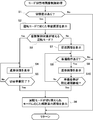
以上の構成からなる表示装置100は、図3(a)~(c)に示す経路案内画像以外の報知画像を表示することが可能であるが、以下では、図4~図7を参照して、本実施形態に特有のモード切替時画像制御処理について説明する。例えば、車両2のイグニッションのオンに伴って、表示装置100に動作電力の供給が開始されると、CPU21が起動する。モード切替時画像制御処理は、例えばナビゲーションシステムの起動に応じて開始される。なお、以下の処理では、説明の理解を容易にするため、図示しない表示制御部については言及しないが、以下の処理は、CPU21が表示制御部を介して実行する制御も含むものとする。
(モード切替時画像制御処理)
まず、CPU21は、運転モードの切替指示があるか否かを判別する(ステップS1)。具体的には、CPU21は、ECU230から切替指示コマンドを受け付けた場合に、切替指示があったと判別する。なお、ステップS1の処理時においては、ナビゲーションシステム起動直後では、図3(a)に示す経路案内画像が、後述のステップS6を実行後においては、図3(a)~図3(c)のいずれかに示す経路案内画像が表示手段10に表示されているものとする。
まず、CPU21は、運転モードの切替指示があるか否かを判別する(ステップS1)。具体的には、CPU21は、ECU230から切替指示コマンドを受け付けた場合に、切替指示があったと判別する。なお、ステップS1の処理時においては、ナビゲーションシステム起動直後では、図3(a)に示す経路案内画像が、後述のステップS6を実行後においては、図3(a)~図3(c)のいずれかに示す経路案内画像が表示手段10に表示されているものとする。
運転モードの切替指示があった場合(ステップS1;Yes)、CPU21は、当該切替指示に応じた準備画面Pを表示手段10に表示させる(ステップS2)。準備画面Pについては後述する。
続いて、CPU21は、切替後の運転モードが切替前よりも自動制御対象が増える運転モードであるか否かを判別する(ステップS3)。
切替後の運転モードが切替前よりも自動制御対象が増える運転モードである場合(ステップS3;Yes)、CPU21は、進捗画像Qを表示手段10に表示させる(ステップS4)。以下、このようにステップS3でYesと判別される場合の処理を、図5(a)~(d)に示す画像制御例を参照しつつ説明する。
図5(a)~(d)は、手動運転モードから第2自動運転モードへと切り替えられる場合の画像制御例を示している。この場合、ステップS1実行時には、図5(a)に示す手動運転モード時の経路案内画像が表示手段10に表示されている。続いて、切替指示(ここでは、第2自動運転モードへの切替指示)があった場合(ステップS1;Yes)、CPU21は、表示手段10に図5(b)に示すような準備画面Pを表示させる(ステップS2)。
図5の例は、手動運転モードから第2自動運転モードへの切替、つまり切替後の自動制御対象が増える例であるため、ステップS3でYesと判別され、CPU21は、準備画面P内に、運転モード切替までの進捗を示す進捗画像Qを表示させる(ステップS4)。切替準備が完了するまでは(ステップS5;No)、進捗画像Qが継続して表示される。
進捗画像Qは、図5(b)及び図5(c)に示すように、表示手段10による表示像を虚像Vとして視認する運転者4から見て、手前から奥方向に延びるようなバーグラフ態様で表示される。この実施形態では、進捗画像Qは走行車線の幅員を示すような態様で表示される。具体的には、進捗画像Qは、例えば走行車線の左右両側の白線(実際の道路上の白線)に沿うように、遠近感を認識可能に、二本のバーが手前から奥方向に延びる態様で表示される。そして、CPU21は、切替準備完了までの進捗に合わせて、進捗画像Qにおいて指標量Q1を、虚像Vを視認する運転者4から見ての「手前から奥」に向かって増加させる画像制御を行う。なお、CPU21は、切替準備の進捗について、ECU230からの情報に基づいて特定可能である。また、運転モード切替準備完了までの期間は、車両2側で運転モード切替準備完了までに要する期間、あるいは、運転者4に余裕を持たせるため、当該期間よりも大きい期間が予め定められている。
また、ステップS4で進捗画像Qを表示させると共に、CPU21は、切替後の運転モードを示唆する示唆画像Rを、図5(b)及び図5(c)に示すように、指標量Q1の増加側に表示させる。ここでの示唆画像Rは、設定された目的地に関する情報を示す態様で経路案内画像が表示される第2自動運転モードへの移行を示唆すべく、目的地を概略的に示す「フラッグ」のアイコン画像である。
なお、示唆画像Rは、切替後の運転モードを示唆することができれば、アイコンに限られず、文字や図形であってもよいし、これらの組み合わせからなる画像であってもよい(後述の図6(b)などにおいても同様)。
運転モードの切替準備が完了すると(ステップS5;Yes)、車両2側で実際に運転モードが切り替えられ、これに応じて、CPU21は、当該運転モードに応じて経路案内画像(図5(d)参照)を表示手段10に表示させる(ステップS6)。なお、切替準備が完了すれば、このように車両2側で直ちに運転モードが切り替えられるため、進捗画像Qは、切替完了までの進捗を示す。
なお、図示しないが、手動運転モードから第1自動運転モードへの切替時や、第1自動運転モードから第2自動運転モードへの切替時においても同様に、切替準備完了までの進捗に合わせて、進捗画像Qにおける指標量Q1を、虚像Vを視認する運転者4から見ての「手前から奥」に向かって増加させることで、進捗報知が行われる。
ステップS3において、切替後の運転モードが切替前よりも自動制御対象が減る運転モードである場合(ステップS3;No)、CPU21は、促進画像Tを表示手段10に表示させる(ステップS7)。以下、このようにステップS3でNoと判別される場合の処理を、図6(a)~(d)に示す画像制御例を参照しつつ説明する。
図6(a)~(d)は、第2自動運転モードから第1運転モードへと切り替えられる場合の画像制御例を示している。この場合、ステップS1実行時には、図6(a)に示す第2自動運転モード時の経路案内画像が表示手段10に表示されている。続いて、切替指示(ここでは、手動運転モードへの切替指示)があった場合(ステップS1;Yes)、CPU21は、表示手段10に図6(b)に示すような準備画面Pを表示させる(ステップS2)。
図6の例は、第2自動運転モードから第1手動運転モードへの切替、つまり切替後の自動制御対象が減る例であるため、ステップS3でNoと判別され、CPU21は、準備画面P内に、促進画像Tを表示させる(ステップS7)。
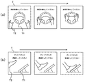
促進画像Tは、図6(b)及び図6(c)に示すように、より詳細には図7(a)に示すように、車両2の備品画像T1と、運転者2の身体を模した身体画像T2とを含む態様で表示される。
第2自動運転モードから第1自動運転モードへと切り替えられる例では、モード切替後に操舵の自動制御が解除されるため、CPU21は、表示手段10に操舵準備を促す促進画像Tを表示させる。この場合、図7(a)に示すように、備品画像T1は車両2のステアリングホイールを表し、身体画像T2は運転者4の手を模した画像が表示される。そして、例えば、後述のステップS8で準備動作があったと判別されるまでは、図7(a)に示すように、備品画像T1に向かって身体画像T2が移動するようなアニメーションを表示することにより、運転者4に操舵準備を促す。
なお、第1自動運転モードから手動運転モードへと切り替えられる例では、モード切替後に加減速の自動制御が解除されるため、CPU21は、表示手段10にフットペダル(例えばアクセルペダル。場合によってはブレーキペダルであってもよい)の操作準備を促す促進画像Tを表示させる。この場合、図7(b)に示すように、備品画像T1は車両2のフットペダルを表し、身体画像T2は運転者4の足を模した画像が表示される。そして、例えば、後述のステップS8で準備動作があったと判別されるまでは、図7(b)に示すように、備品画像T1に向かって身体画像T2が移動するようなアニメーションを表示することにより、運転者4に加減速操作の準備を促す。また、第2自動運転モードから手動運転モードへと切り替えられる場合は、図7(a)と図7(b)の双方に示すような画像を同時に表示させるようにしてもよい。
続いて、CPU21は、促進画像Tが示す内容に応じた準備動作があったか否かを判別する(ステップS8)。具体的には、所定時間(例えば、数秒)内に準備動作が行われたことを示す準備動作検出信号を動作検出部220またはECU230から取得したか否かが判別される。準備動作が所定時間内に無かった場合(ステップS8;No)、運転者4による準備ができていないと見做せるため、CPU21は、処理をステップS1に戻す。この場合は、切替指示前の経路案内画像に再び戻されることになる。
準備動作が所定時間内にあった場合(ステップS8;Yes)、CPU21は、準備画面P内に、運転モード切替までの進捗を示す進捗画像Qを表示手段10に表示させる(ステップS9)。後述のステップS10でYesと判別されるまでは、進捗画像Qが継続して表示される。
進捗画像Qは、図6(b)及び図6(c)に示すように、表示手段10による表示像を虚像Vとして視認する運転者4から見て、手前から奥方向に延びるようなバーグラフ態様で表示される。当該態様は、図5(b)及び図5(c)を参照して説明した態様と同様である。ただし、切替後の運転モードが、自動制御対象が減るものである場合は、CPU21は、切替準備完了までの進捗に合わせて、進捗画像Qにおいて指標量Q1を、虚像Vを視認する運転者4から見ての「奥から手前」に向かって増加させる画像制御を行う。
また、ステップS9で進捗画像Qを表示させると共に、CPU21は、切替後の運転モードを示唆する示唆画像Rを、図6(b)及び図6(c)に示すように、虚像Vを視認する運転者4から見ての奥側に表示させる。ここでの示唆画像Rは、加減速制御が実行される第1自動運転モードへの移行を示唆すべく、走行車両を示すアイコン画像である。
ステップS9に続いて、CPU21は、運転者4による準備姿勢が所定期間継続されているか否かを判別する(ステップS10)。切替後の運転モードが切替前よりも自動制御対象が減るものである場合は、運転者4に何らかの操作が必要となるため、車両2側でモード切替準備が完了して直ちにモード移行が完了してしまっては、安全の観点から適切ではない。したがって、この実施形態では、このような処理を設けることにより安全を担保している。そのため、例えば、ここでの所定期間は、実際に車両2側で切替準備のために必要となる期間以上の期間が予め定められている。
準備姿勢が所定期間継続されなかった場合(ステップS10;No)は、CPU21は、ステップS8に処理を戻す。そして、ステップS8において準備動作がないと判別されれば(ステップS8;No)、処理をステップS1に戻す。この場合は、切替指示前の経路案内画像に再び戻されることになる。前述のように、運転者4による準備ができていないと見做せるためである。
一方で、準備姿勢が所定期間継続された場合(ステップS10;Yes)、車両2側で実際に運転モードが切り替えられ、これに応じて、CPU21は、当該運転モードに応じて経路案内画像(図6(d)参照)を表示手段10に表示させる(ステップS6)。
なお、図示しないが、第2自動運転モードから手動運転モードへの切替時や、第1自動運転モードから手動運転モードへの切替時においても同様に、切替準備完了までの進捗に合わせて、進捗画像Qにおける指標量Q1を、虚像Vを視認する運転者4から見ての「奥から手前」に向かって増加させることで、進捗報知が行われる。
CPU21は、以上のモード切替時画像制御処理を、例えばナビゲーションシステムがオフされるまで繰り返し実行する。
なお、図5(a)に示す手動運転モード時の経路案内画像から、図5(b)に示す準備画面Pへの遷移は、当該経路案内画像に示される目的地近傍が徐々に拡大していくような態様(ズームインする態様)で実行される。また、図5(a)に示す経路案内画像が車両2の進行方向が上向きとなるヘッドアップ表示で無い場合(例えばノースアップ表示時など)は、図5(b)に示す準備画面への遷移は、前記のようにズームインさせると共に、回転させながら遷移させる態様とすれば、運転者4にとっての実際の感覚とも合致し、視覚効果にも優れるため良い。
また、図5(c)に示す準備画面Pから、図5(d)に示す経路案内画像への遷移は、ズームアウトする態様で実行される。具体的には例えば、図5(c)に示されている目的地を示すアイコンが徐々に小さくなっていき、図5(d)に示す経路案内画像へと変化する態様である。
また、図5(c)に示す準備画面Pから、図5(d)に示す経路案内画像への遷移は、ズームアウトする態様で実行される。具体的には例えば、図5(c)に示されている目的地を示すアイコンが徐々に小さくなっていき、図5(d)に示す経路案内画像へと変化する態様である。
同様に、図6(a)に示す第2自動運転モード時の経路案内画像から、図6(b)に示す準備画面Pへの遷移は、当該経路案内画像が徐々に拡大していくような態様(ズームインする態様)で実行される。具体的には、地図を示す特定の地点(例えば、現在の車両2の位置に相当する地点)が拡大していき、図6(b)に示す準備画面Pへと変化するような態様である。
また、図6(c)に示す準備画面Pから、図6(d)に示す経路案内画像への遷移は、ズームアウトする態様で実行される。具体的には例えば、図6(c)に示されている走行車両を示すアイコンが徐々に小さくなっていき、図6(d)に示す経路案内画像へと変化する態様である。ここで、車両2の進行方向が上向きとなるヘッドアップ表示に設定されていない場合(例えばノースアップ表示時など)は、図6(c)から図6(d)に示す経路案内画像への遷移は、前記のようにズームアウトさせると共に、回転させながら遷移させる態様とすれば、運転者2にとっての実際の感覚とも合致し、視覚効果にも優れるため良い。
また、図6(c)に示す準備画面Pから、図6(d)に示す経路案内画像への遷移は、ズームアウトする態様で実行される。具体的には例えば、図6(c)に示されている走行車両を示すアイコンが徐々に小さくなっていき、図6(d)に示す経路案内画像へと変化する態様である。ここで、車両2の進行方向が上向きとなるヘッドアップ表示に設定されていない場合(例えばノースアップ表示時など)は、図6(c)から図6(d)に示す経路案内画像への遷移は、前記のようにズームアウトさせると共に、回転させながら遷移させる態様とすれば、運転者2にとっての実際の感覚とも合致し、視覚効果にも優れるため良い。
(1)以上に説明した表示装置100は、自動運転モードを含む複数の運転モードによる制御が可能な車両2に搭載される画像制御装置(例えば制御手段20の機能を有する構成)を有する。
当該画像制御装置は、運転モードの切替指示を受け付けたことに応じて、該運転モードの切替完了までの進捗を指標量Q1の増加によって示す進捗画像Qを表示手段10に表示させる表示制御手段(例えば制御手段20)を備える。
表示制御手段は、切替後の運転モードが切替前よりも車両2における自動制御対象が増えるものである場合は、進捗画像Qにおける指標量Q1を所定の順方向(例えば、運転者4から見ての手前から奥に向かう方向)に沿って増加させ、切替後の運転モードが切替前よりも車両2における自動制御対象が減るものである場合は、進捗画像Qにおける指標量Q1を前記順方向の逆方向(例えば、運転者4から見ての奥から手前に向かう方向)に沿って増加させる。
このようにしたから、運転モードの切替タイミングが把握でき、運転者4が準備し易い。
当該画像制御装置は、運転モードの切替指示を受け付けたことに応じて、該運転モードの切替完了までの進捗を指標量Q1の増加によって示す進捗画像Qを表示手段10に表示させる表示制御手段(例えば制御手段20)を備える。
表示制御手段は、切替後の運転モードが切替前よりも車両2における自動制御対象が増えるものである場合は、進捗画像Qにおける指標量Q1を所定の順方向(例えば、運転者4から見ての手前から奥に向かう方向)に沿って増加させ、切替後の運転モードが切替前よりも車両2における自動制御対象が減るものである場合は、進捗画像Qにおける指標量Q1を前記順方向の逆方向(例えば、運転者4から見ての奥から手前に向かう方向)に沿って増加させる。
このようにしたから、運転モードの切替タイミングが把握でき、運転者4が準備し易い。
なお、順方向は、運転者4から見ての手前から奥に向かう方向(車両2の進行方向に対応)に限られない。運転者4から見ての左右いずれかの方向などであってもよい。ただし、順方向を車両2の進行方向と対応させた方が、自動制御対象の増減を感覚的に運転者4に認識させやすいため、ユーザフレンドリであり好ましい。
(2)また、表示制御手段は、切替指示を受け付けたことに応じて、切替後の運転モードを示唆する示唆画像Rを、表示手段10の表示領域(虚像Vの表示領域に対応)における順方向側に偏在した位置(図5(b)、図6(b)参照)に表示させる。
このように、車両2の進行方向に対応した方向に偏在して示唆画像Rが表示されるため、切替先の運転モードを認識させやすい。
このように、車両2の進行方向に対応した方向に偏在して示唆画像Rが表示されるため、切替先の運転モードを認識させやすい。
なお、自動制御対象が減る場合などには、順方向とは逆方向側に偏在した位置に示唆画像Rを表示させてもよい。つまり、自動制御対象が増える場合だけでなく、減る場合においても、指標量Q1の増加側に示唆画像Rを表示させてもよい。
さらに、示唆画像Rは、切替前の運転モードを示唆するものを表示させてもよい。切替指示を受け付けたことに応じて、切替後の運転モードを示唆する示唆画像Rを、表示手段10の表示領域における順方向側に偏在した位置に表示させる場合においては、切替前の運転モードを示唆する示唆画像Rを、表示手段10の表示領域における順方向とは逆方向側に偏在した位置に表示させるようにすることが好ましい。
さらに、示唆画像Rは、切替前の運転モードを示唆するものを表示させてもよい。切替指示を受け付けたことに応じて、切替後の運転モードを示唆する示唆画像Rを、表示手段10の表示領域における順方向側に偏在した位置に表示させる場合においては、切替前の運転モードを示唆する示唆画像Rを、表示手段10の表示領域における順方向とは逆方向側に偏在した位置に表示させるようにすることが好ましい。
(3)また、表示制御手段は、切替指示を受け付けたことに応じて、切替後の運転モードに応じた準備を運転者4に促す促進画像Tを表示手段10に表示させる。
(4)より具体的には、表示制御手段は、切替後の運転モードが切替前よりも車両2における自動制御対象が減るものである場合に、促進画像Tを表示させる。
このようにしたから、運転モード切替時の安全を担保することができる。
(4)より具体的には、表示制御手段は、切替後の運転モードが切替前よりも車両2における自動制御対象が減るものである場合に、促進画像Tを表示させる。
このようにしたから、運転モード切替時の安全を担保することができる。
なお、切替後の運転モードが切替前よりも車両2における自動制御対象が増えるものである場合にも、促進画像Tを表示させるようにしてもよい。
(5)促進画像Tは、車両2の備品画像T1と、備品画像T1に向かって移動する運転者4の身体を模した身体画像T2とを含む。
このようにしたから、運転者4はどのような準備動作をしたらよいかを容易に把握することができる。
このようにしたから、運転者4はどのような準備動作をしたらよいかを容易に把握することができる。
(6)表示制御手段は、複数の運転モードの種類に応じた態様で経路案内画像を表示手段10に表示させ、切替後の運転モードが切替前よりも車両2における自動制御対象が増えるものである場合は、切替後の運転モードにおいて切替前よりも経路案内画像を概略的な態様で表示させ、切替後の運転モードが切替前よりも車両2における自動制御対象が減るものである場合は、切替後の運転モードにおいて切替前よりも経路案内画像を詳細な態様で表示させる。
このように、経路案内画像を運転モードに応じた態様で表示させることで、現在の運転モードを容易に把握させることができる。
このように、経路案内画像を運転モードに応じた態様で表示させることで、現在の運転モードを容易に把握させることができる。
(7)変形例として、運転モードの切替完了までの進捗を、当該切替完了までの残時間と対応させた指標量によって示しても良い。この場合は、切替完了に近づくにつれて、進捗画像における指標量が減少する態様での表示制御を行えばよい。
つまり、このような変形例に係る画像制御装置は、運転モードの切替指示を受け付けたことに応じて、該運転モードの切替完了までの進捗を指標量の減少によって示す進捗画像を表示手段に表示させる表示制御手段を備える。表示制御手段は、切替後の運転モードが切替前よりも車両2における自動制御対象が増えるものである場合は、進捗画像における指標量を所定の順方向に沿って減少させ、切替後の運転モードが切替前よりも車両2における自動制御対象が減るものである場合は、進捗画像における指標量を前記順方向の逆方向に沿って減少させる。
このような変形例においても、運転モードの切替タイミングが把握でき、運転者4が準備し易い。
つまり、このような変形例に係る画像制御装置は、運転モードの切替指示を受け付けたことに応じて、該運転モードの切替完了までの進捗を指標量の減少によって示す進捗画像を表示手段に表示させる表示制御手段を備える。表示制御手段は、切替後の運転モードが切替前よりも車両2における自動制御対象が増えるものである場合は、進捗画像における指標量を所定の順方向に沿って減少させ、切替後の運転モードが切替前よりも車両2における自動制御対象が減るものである場合は、進捗画像における指標量を前記順方向の逆方向に沿って減少させる。
このような変形例においても、運転モードの切替タイミングが把握でき、運転者4が準備し易い。
(8)また、以上に説明した表示装置100は、表示手段10と、前記の画像制御装置と、を備え、表示手段10からの表示光Lを透光部材(例えばフロントガラス3)に投射することで、透光部材の前方に表示光Lによる像を表示する。
なお、本発明は以上の実施形態、変形例、及び図面によって限定されるものではない。本発明の要旨を変更しない範囲で、適宜、変更(構成要素の削除も含む)を加えることが可能である。
表示光Lの投射対象は、フロントガラス3に限定されず、板状のハーフミラー、ホログラム素子等により構成されるコンバイナであってもよい。
また、進捗画像Qは、走行車線の幅員を表すように二つのバーグラフ態様で表示するものとしたが、これに限られない。運転者2から見ての上下方向に沿うような1本のバーグラフ態様であってもよい。ただし、前記のように遠近感を考慮した、二つのバーグラフ態様により進捗画像Qを表示したほうが、実景に重畳される表示としては煩雑でなく、好ましい。また、進捗画像Qは、所定の方向に沿って指標量が増減する態様であればよく、画像デザインや、運転者4の認識のし易さに応じて、任意である。
また、表示装置100や車両用表示システム1が搭載される乗り物は、車両2(自動四輪車だけでなく、自動二輪車なども含む)に限られない。当該乗り物は、車両以外の船舶、航空機、水上バイク、雪上バイクなどであってもよい。
また、前記の動作プログラムは、予め記憶部22のROMに記憶されているものとしたが、着脱自在の記録媒体により配布・提供されてもよい。また、動作プログラムは、表示装置100と接続された他の機器からダウンロードされるものであってもよい。また、表示装置100は、他の機器と電気通信ネットワークなどを介して各種データの交換を行うことにより前記の動作プログラムに従う各処理を実行してもよい。
以上の説明では、本発明の理解を容易にするために、公知の技術的事項の説明を適宜省略した。
本発明は、車両情報を運転者に表示させる車両用表示システムに適している。
1…車両用表示システム
2…車両、3…フロントガラス、4…運転者
100…表示装置
10…表示手段
L…表示光、V…虚像
P…準備画面
Q…進捗画像、Q1…指標量
R…示唆画像
T…促進画像、T1…備品画像、T2…身体画像
20…制御手段
21…CPU、22…記憶部、23…ビデオメモリ
210…状況解析部
220…動作検出部
230…ECU
2…車両、3…フロントガラス、4…運転者
100…表示装置
10…表示手段
L…表示光、V…虚像
P…準備画面
Q…進捗画像、Q1…指標量
R…示唆画像
T…促進画像、T1…備品画像、T2…身体画像
20…制御手段
21…CPU、22…記憶部、23…ビデオメモリ
210…状況解析部
220…動作検出部
230…ECU
Claims (8)
- 自動運転モードを含む複数の運転モードによる制御が可能な乗り物に搭載される画像制御装置であって、
運転モードの切替指示を受け付けたことに応じて、該運転モードの切替完了までの進捗を指標量の増加によって示す進捗画像を表示手段に表示させる表示制御手段を備え、
前記表示制御手段は、
切替後の運転モードが切替前よりも前記乗り物における自動制御対象が増えるものである場合は、前記進捗画像における指標量を所定の順方向に沿って増加させ、
切替後の運転モードが切替前よりも前記乗り物における自動制御対象が減るものである場合は、前記進捗画像における指標量を前記順方向の逆方向に沿って増加させる、
ことを特徴とする画像制御装置。 - 前記表示制御手段は、
前記切替指示を受け付けたことに応じて、切替後の運転モードを示唆する示唆画像を、前記表示手段の表示領域における前記順方向側または前記逆方向側に偏在した位置に表示させる、
ことを特徴とする請求項1に記載の画像制御装置。 - 前記表示制御手段は、
前記切替指示を受け付けたことに応じて、切替後の運転モードに応じた準備を運転者に促す促進画像を前記表示手段に表示させる、
ことを特徴とする請求項1又は2に記載の画像制御装置。 - 前記表示制御手段は、
切替後の運転モードが切替前よりも前記乗り物における自動制御対象が減るものである場合に、前記促進画像を表示させる、
ことを特徴とする請求項3に記載の画像制御装置。 - 前記促進画像は、前記乗り物の備品画像と、前記備品画像に向かって移動する身体画像とを含む、
ことを特徴とする請求項3又は4に記載の画像制御装置。 - 前記表示制御手段は、前記複数の運転モードの種類に応じた態様で経路案内画像を前記表示手段に表示させ、
切替後の運転モードが切替前よりも前記乗り物における自動制御対象が増えるものである場合は、切替後の運転モードにおいて切替前よりも経路案内画像を概略的な態様で表示させ、
切替後の運転モードが切替前よりも前記乗り物における自動制御対象が減るものである場合は、切替後の運転モードにおいて切替前よりも経路案内画像を詳細な態様で表示させる、
ことを特徴とする請求項1乃至5のいずれか1項に記載の画像制御装置。 - 自動運転モードを含む複数の運転モードによる制御が可能な乗り物に搭載される画像制御装置であって、
運転モードの切替指示を受け付けたことに応じて、該運転モードの切替完了までの進捗を指標量の減少によって示す進捗画像を表示手段に表示させる表示制御手段を備え、
前記表示制御手段は、
切替後の運転モードが切替前よりも前記乗り物における自動制御対象が増えるものである場合は、前記進捗画像における指標量を所定の順方向に沿って減少させ、
切替後の運転モードが切替前よりも前記乗り物における自動制御対象が減るものである場合は、前記進捗画像における指標量を前記順方向の逆方向に沿って減少させる、
ことを特徴とする画像制御装置。 - 前記表示手段と、請求項1乃至7のいずれか1項に記載の画像制御装置と、を備え、
前記表示手段からの表示光を透光部材に投射することで、前記透光部材の前方に前記表示光による像を表示する表示装置。
Priority Applications (2)
| Application Number | Priority Date | Filing Date | Title |
|---|---|---|---|
| US16/315,455 US20190308641A1 (en) | 2016-07-14 | 2017-07-11 | Image control apparatus and display apparatus |
| JP2018527603A JP6939789B2 (ja) | 2016-07-14 | 2017-07-11 | 画像制御装置及び表示装置 |
Applications Claiming Priority (2)
| Application Number | Priority Date | Filing Date | Title |
|---|---|---|---|
| JP2016-139594 | 2016-07-14 | ||
| JP2016139594 | 2016-07-14 |
Publications (1)
| Publication Number | Publication Date |
|---|---|
| WO2018012474A1 true WO2018012474A1 (ja) | 2018-01-18 |
Family
ID=60952518
Family Applications (1)
| Application Number | Title | Priority Date | Filing Date |
|---|---|---|---|
| PCT/JP2017/025191 Ceased WO2018012474A1 (ja) | 2016-07-14 | 2017-07-11 | 画像制御装置及び表示装置 |
Country Status (3)
| Country | Link |
|---|---|
| US (1) | US20190308641A1 (ja) |
| JP (1) | JP6939789B2 (ja) |
| WO (1) | WO2018012474A1 (ja) |
Cited By (7)
| Publication number | Priority date | Publication date | Assignee | Title |
|---|---|---|---|---|
| JP2019156232A (ja) * | 2018-03-14 | 2019-09-19 | 本田技研工業株式会社 | 車両制御装置 |
| JP2020024551A (ja) * | 2018-08-07 | 2020-02-13 | トヨタ自動車株式会社 | 運転意識推定装置 |
| JP2020032830A (ja) * | 2018-08-29 | 2020-03-05 | トヨタ自動車株式会社 | 車両用表示装置 |
| US11008016B2 (en) * | 2018-03-15 | 2021-05-18 | Honda Motor Co., Ltd. | Display system, display method, and storage medium |
| JP2022041243A (ja) * | 2020-08-31 | 2022-03-11 | トヨタ自動車株式会社 | 車両用表示制御装置、車両用表示システム、車両用表示制御方法及び車両用表示制御プログラム |
| WO2023171458A1 (ja) * | 2022-03-07 | 2023-09-14 | 株式会社デンソー | 車両用報知制御装置及び車両用報知制御方法 |
| JP2023130310A (ja) * | 2022-03-07 | 2023-09-20 | 株式会社デンソー | 車両用報知制御装置及び車両用報知制御方法 |
Families Citing this family (6)
| Publication number | Priority date | Publication date | Assignee | Title |
|---|---|---|---|---|
| US11215451B2 (en) * | 2017-09-20 | 2022-01-04 | Continental Automotive Systems, Inc. | Trailer length detection system |
| US10935974B1 (en) * | 2018-04-19 | 2021-03-02 | State Farm Mutual Automobile Insurance Company | Manual control re-engagement in an autonomous vehicle |
| FR3084634B1 (fr) * | 2018-08-01 | 2021-07-30 | Renault Sas | Systeme d'affichage d'informations par selection manuelle ou automatique parmi une pluralite de modes d'affichage classes par en fonction de leur niveau de decentrage par rapport au vehicule |
| US12333067B2 (en) | 2020-09-23 | 2025-06-17 | Apple Inc. | Detecting unexpected user interface behavior using physiological data |
| FR3115009B1 (fr) * | 2020-10-09 | 2023-03-10 | Renault Sas | Procédé d’aide à la conduite d’un véhicule automobile |
| JP7767738B2 (ja) * | 2021-06-01 | 2025-11-12 | マツダ株式会社 | ヘッドアップディスプレイ装置 |
Citations (3)
| Publication number | Priority date | Publication date | Assignee | Title |
|---|---|---|---|---|
| JP2011118603A (ja) * | 2009-12-02 | 2011-06-16 | Clarion Co Ltd | 車両制御装置 |
| JP2015182624A (ja) * | 2014-03-25 | 2015-10-22 | 日産自動車株式会社 | 情報表示装置 |
| JP2015219128A (ja) * | 2014-05-19 | 2015-12-07 | アルパイン株式会社 | ナビゲーション装置、ナビゲーション装置における経路案内制御方法及びプログラム |
Family Cites Families (1)
| Publication number | Priority date | Publication date | Assignee | Title |
|---|---|---|---|---|
| JP6237656B2 (ja) * | 2015-01-19 | 2017-11-29 | トヨタ自動車株式会社 | 車両システム |
-
2017
- 2017-07-11 JP JP2018527603A patent/JP6939789B2/ja active Active
- 2017-07-11 US US16/315,455 patent/US20190308641A1/en not_active Abandoned
- 2017-07-11 WO PCT/JP2017/025191 patent/WO2018012474A1/ja not_active Ceased
Patent Citations (3)
| Publication number | Priority date | Publication date | Assignee | Title |
|---|---|---|---|---|
| JP2011118603A (ja) * | 2009-12-02 | 2011-06-16 | Clarion Co Ltd | 車両制御装置 |
| JP2015182624A (ja) * | 2014-03-25 | 2015-10-22 | 日産自動車株式会社 | 情報表示装置 |
| JP2015219128A (ja) * | 2014-05-19 | 2015-12-07 | アルパイン株式会社 | ナビゲーション装置、ナビゲーション装置における経路案内制御方法及びプログラム |
Cited By (14)
| Publication number | Priority date | Publication date | Assignee | Title |
|---|---|---|---|---|
| JP2019156232A (ja) * | 2018-03-14 | 2019-09-19 | 本田技研工業株式会社 | 車両制御装置 |
| JP7144947B2 (ja) | 2018-03-14 | 2022-09-30 | 本田技研工業株式会社 | 車両制御装置 |
| US11008016B2 (en) * | 2018-03-15 | 2021-05-18 | Honda Motor Co., Ltd. | Display system, display method, and storage medium |
| JP7210929B2 (ja) | 2018-08-07 | 2023-01-24 | トヨタ自動車株式会社 | 運転意識推定装置 |
| JP2020024551A (ja) * | 2018-08-07 | 2020-02-13 | トヨタ自動車株式会社 | 運転意識推定装置 |
| JP2020032830A (ja) * | 2018-08-29 | 2020-03-05 | トヨタ自動車株式会社 | 車両用表示装置 |
| JP7346801B2 (ja) | 2018-08-29 | 2023-09-20 | トヨタ自動車株式会社 | 車両用表示装置、表示方法及びプログラム |
| JP2022041243A (ja) * | 2020-08-31 | 2022-03-11 | トヨタ自動車株式会社 | 車両用表示制御装置、車両用表示システム、車両用表示制御方法及び車両用表示制御プログラム |
| JP7484590B2 (ja) | 2020-08-31 | 2024-05-16 | トヨタ自動車株式会社 | 車両用表示制御装置、車両用表示システム、車両用表示制御方法及び車両用表示制御プログラム |
| JP2024097863A (ja) * | 2020-08-31 | 2024-07-19 | トヨタ自動車株式会社 | 車両用表示制御装置、車両用表示システム、車両用表示制御方法及び車両用表示制御プログラム |
| JP2024097864A (ja) * | 2020-08-31 | 2024-07-19 | トヨタ自動車株式会社 | 車両用表示制御装置、車両用表示システム、車両用表示制御方法及び車両用表示制御プログラム |
| WO2023171458A1 (ja) * | 2022-03-07 | 2023-09-14 | 株式会社デンソー | 車両用報知制御装置及び車両用報知制御方法 |
| JP2023130310A (ja) * | 2022-03-07 | 2023-09-20 | 株式会社デンソー | 車両用報知制御装置及び車両用報知制御方法 |
| JP7658386B2 (ja) | 2022-03-07 | 2025-04-08 | 株式会社デンソー | 車両用報知制御装置及び車両用報知制御方法 |
Also Published As
| Publication number | Publication date |
|---|---|
| JPWO2018012474A1 (ja) | 2019-04-25 |
| JP6939789B2 (ja) | 2021-09-22 |
| US20190308641A1 (en) | 2019-10-10 |
Similar Documents
| Publication | Publication Date | Title |
|---|---|---|
| JP6939789B2 (ja) | 画像制御装置及び表示装置 | |
| JP7188575B2 (ja) | 表示制御方法及び表示制御装置 | |
| JP6414096B2 (ja) | 車載装置、車載装置の制御方法及び車載装置の制御プログラム | |
| JP7140278B2 (ja) | 表示制御方法及び表示制御装置 | |
| JP7124963B2 (ja) | 運転支援方法及び運転支援装置 | |
| JP6176478B2 (ja) | 車両情報投影システム | |
| JP6544320B2 (ja) | 自動運転車両の制御システム及び制御方法 | |
| JP6417994B2 (ja) | 車両用表示制御装置及び車両用表示制御方法 | |
| JP7697309B2 (ja) | 表示制御装置及び表示制御プログラム | |
| JP7346859B2 (ja) | 制御装置、表示装置、移動体、制御方法、及びプログラム | |
| JP6361794B2 (ja) | 車両情報投影システム | |
| JP6604577B2 (ja) | 運転支援方法およびそれを利用した運転支援装置、運転支援システム、自動運転制御装置、車両、プログラム | |
| JP2022020688A (ja) | 車両用表示制御装置、車両用表示制御方法、及び制御プログラム | |
| WO2019189515A1 (en) | Control apparatus, display apparatus, movable body, and image display method | |
| JP7255429B2 (ja) | 表示制御装置および表示制御プログラム | |
| JP2018030531A (ja) | 自動運転車両の制御システム及び制御方法 | |
| WO2020189238A1 (ja) | 車両用表示制御装置、車両用表示制御方法、車両用表示制御プログラム | |
| JP5614079B2 (ja) | 運転支援装置 | |
| US12319305B2 (en) | Display control device, display control method, and recording medium | |
| JP7275985B2 (ja) | 表示制御装置 | |
| JP7302311B2 (ja) | 車両用表示制御装置、車両用表示制御方法、車両用表示制御プログラム | |
| JP7172730B2 (ja) | 車両用表示制御装置、車両用表示制御方法、車両用表示制御プログラム | |
| JP6610376B2 (ja) | 表示装置 | |
| JP2020138609A (ja) | 車両用表示制御装置、車両用表示制御方法、車両用表示制御プログラム | |
| JP2022071307A (ja) | ヘッドアップディスプレイ装置 |
Legal Events
| Date | Code | Title | Description |
|---|---|---|---|
| 121 | Ep: the epo has been informed by wipo that ep was designated in this application |
Ref document number: 17827601 Country of ref document: EP Kind code of ref document: A1 |
|
| ENP | Entry into the national phase |
Ref document number: 2018527603 Country of ref document: JP Kind code of ref document: A |
|
| NENP | Non-entry into the national phase |
Ref country code: DE |
|
| 122 | Ep: pct application non-entry in european phase |
Ref document number: 17827601 Country of ref document: EP Kind code of ref document: A1 |